for removal, upgrade, repair, monitoring of underground
TRANSCRIPT

PERMIT APPLICATION GUIDANCE DOCUMENT
FOR REMOVAL, UPGRADE, REPAIR, MONITORING OF UNDERGROUND AND ABOVEGROUND STORAGE TANKS.
Long Beach Fire Department City of Long Beach Department of Health & Human Bureau of Fire Prevention Services Department 3205 Lakewood Blvd. Hazardous Materials Division Long Beach, CA 90808 2525 Grand Avenue, Suite 222, (562) 570-2560 Long Beach, CA 90815 (562) 570-4129
THE LONG BEACH FIRE DEPARTMENT BUREAU OF FIRE PREVENTION AND THE LONG BEACH DEPARTMENT OF HEALTH AND HUMAN SERVICES FORM A CERTIFIED UNIFIED PROGRAM AGENCY (CUPA). AMONG THE RESPONSIBILITIES OF THE LONG BEACH CUPA, IS THE REGULATORY OVERSIGHT OF THE UNDERGROUND AND ABOVEGROUND STORAGE TANK PROGRAMS. THIS PERMIT APPLICATION GUIDANCE HAS BEEN DESIGNED FOR YOUR USE AS A REFERENCE DOCUMENT. PROVIDE ONLY THOSE PAGES, DOCUMENTS AND FEES APPLICABLE TO YOUR PROJECT TO THE CITY OF LONG BEACH CITY HALL, DEVELOPMENT SERVICES CENTER, 333 W. OCEAN BLVD, 4
th FLOOR, LONG BEACH, CA 90802, (562) 570-7086.
Revised October, 2013
INTRODUCTION
Dear Environmental Stakeholder, As the Fire Marshal for the Long Beach Fire Department, my team and I, look forward to partnering with you and your staff in protecting the environment of the great state of California, as well as the City of Long Beach. It is our goal to protect you as well as those who live, work, and enjoy our great city. The California State Legislature has declared that it is “In the public interest to establish a continuing program for the purpose of preventing contamination from, improper storage of hazardous substances stored underground.” The goal of the Long Beach Fire Department, Bureau of Fire Prevention, as stated by legislative declaration, is education as well as the protection of public health, safety and the environment. We are committed to attaining and sustaining this goal into the future to enable future generations to enjoy the treasured resources entrusted to the City of Long Beach. With the advancements of today’s technology and providing state-of-the-art underground and above ground tank systems, I believe that we have the tools needed to accomplish this weighty task. Also, couple this with annual testing, preventative maintenance, timely repairs, and we can be assured that future generations will be entrusted with an environment that has been preserved for their enjoyment. The Long Beach Fire Department is poised to team up with you and your staff as you address these challenges. My team is ready to assist and provide insight, guidance, and direction on issues directly affecting you. My Inspectors and Plan Reviewer’s may be reached by calling (562) 570-2560, during normal business hours (7:00 AM to 5:30 PM) Monday thru Friday. In closing, I would like to personally say “Thank You,” to you, for your commitment to the shared goals we have of protecting the environment. I look forward to partnering in this endeavor with you. Sincerely, Richard Brandt Deputy Chief/Fire Marshal Long Beach Fire Department Bureau of Fire Prevention

TABLE OF CONTENTS REQUIRED PERMITS AND LICENSES...............................................................................1-2 PERMIT APPLICATION…………………………………………………………………………..3-4 FIRE PREVENTION PLAN CHECK APPLICATION ........................................................... .5 CONTRACTORS DECLARATION..........................................................................................6 GENERAL PROJECT INFORMATION ............................................................................... .7 SPECIFIC TOPICS………………………………………………................................................8 REMOVAL, UPGRADES, MODIFICATIONS AND REPAIRS................................................9 CONDEMNED SITE.............................................................................................................10 COMPLIANCE 1998 AND BEYOND...............................................................................11-13 ADDITIONAL LICENSING REQUIREMENTS......................................................................14 HEALTH AND SAFETY – HAZWOPER TRAINING.............................................................14 DESIGN REQUIREMENTS ...............................................................................................15 SITE PLAN/MAP ................................................................................................................16 HEALTH AND SAFETY PLAN ..................................................................................... 17-18 CONFINED SPACES...........................................................................................................18 TANK REMOVAL ...............................................................................................................19 PRIOR TO SUBMITTING PERMIT APPLICATION ...........................................................20 INSPECTORS CHECKLIST ...............................................................................................21 REMOVAL METHOD #1 – HAZARDOUS..........................................................................22 REMOVAL METHOD #2 – CLEAN .............................................................................. 23-24 CLOSURE IN PLACE ........................................................................................................25 TANK INSTALLATION .......................................................................................................26 POLICY ..............................................................................................................................27

CERTIFICATION ...............................................................................................................28 OVERVIEW NEW INSTALLATION ....................................................................................28 AUTOMATIC TANK GAUGE .............................................................................................29 DUAL WALL TANKS WITHOUT STRIKER PLATE ...........................................................29 UNDERGROUND STORAGE TANK INSTALLATION REQUIREMENTS ................... 30-36 WRITTEN MONITORING PROCEDURES ........................................................................37 EMERGENCY RESPONSE PLAN .....................................................................................38 UNDERGROUND STORAGE TANK INSPECTION CHECKLIST ............................... 39-42 ABOVEGROUND STORAGE TANKS ...............................................................................43 APPENDIX A HEALTH DEPARTMENT REQUIREMENTS ......................................... 44-59 MONITORING CERTIFICATION SECTION…………………………………………….…60-63 CERTIFIED UNIFIED PROGRAM AGENCY FORMS – A THROUGH E………………64-77
REQUIRED PERMITS, LICENSES AND FEES
Please initial the line to the left of the following checklist to indicate the permits, licenses and other documents that are required for the project. N/A indicates not applicable.
Copies of all required forms, licenses, certificates, documents and fees must be submitted with this checklist to: City of Long Beach - City Hall Development Services Center 333 W. Ocean Blvd., 4th Floor Long Beach, CA 90802
1. ___ State Contractor License
A. ICC, MFG and HAZWOPER certificates. B. (Copies of applicable certificates and photo identifications for each employee). 2. ___ State of California Worker’s Compensation Insurance information. 3. ___ EPA Generator Identification Number which may be obtained from the State of California Department of Toxic Substances Control (DTSC) Health Services, (916) 255-1136 or (800) 61-TOXIC. 4. ___ City of Long Beach Business License. 5. ___ If the Removal/Installation of the underground tank is to be performed in the City of Long Beach Harbor District, an additional permit is required from the Harbor Planning Bureau, 925 Harbor Plaza Drive, Long Beach, CA 90802, (562) 590-4160.
6. ___ South Coast Air Quality Management District – Degassing Permit (Rule 1149) for all underground tanks larger than 500 gallons. 7. ___ Excavation Safety Precautions. (See page 18). 8. ___ State of California – State Water Resources Control Board Form A, B and C, as complete as possible. (Leave blank if you are not sure – do not write “UNKNOWN”). All forms (A thru E) are located at end of booklet. 9. ___ Site Plan. Minimum of 3 sets are required. (See pages 16). 10.___ Health and Safety Plan (HASP) – (See pages 17-18). 11.___ UNDERGROUND OR ABOVEGROUND STORAGE TANK FEES FOR REVIEW OF SOIL SAMPLING, REMOVAL, OR UPGRADE REPORTS by City of Long Beach Department of Health & Human Services, Bureau of Environmental Health, Division of Hazardous Material.
A. For purposes of removal, ASTs, Clarifiers and Hoists shall be considered underground storage tanks, in regard to soil sampling protocol.
Check Payable to: City of Long Beach for $ 265.00. Mail to: Long Beach Department of Health & Human Services, Division of Hazardous Materials, 2525 Grand Avenue, Room #222, Long Beach, CA 90815.
1

12. FEES: Check Payable to the City of Long Beach.
PLAN TYPE PLAN REVIEW Surcharge: add 6.2%
PLAN PERMIT Surcharge: add 6.2%
Install/Remove/Repair/Sumps/Leak Detection/Slurry Fill
$508.00 for the first tank $202.00 for the first tank $256.00 for each add’l tank
$595.00 $300.00 for each add’l tank
Pipes/VentLines/SB989/Split Boot/Dispensers/Healy/Secondary Containment/CARB/Veeder Root
$450.00 $527.00
UST Monitoring Wells/Smart System $517.00 for first well $225.00 for each add’l well
$607.50 for first well $263.00 per each add’l well
13. ___ Financial Responsibility Documents. 14. ___ For all installations, a written routine monitoring procedure. (See pages 71 and 74). 15. ___ For all installations, a written emergency response plan. (See pages 75 and 77). 16. ___ Completed Application to install storage tanks Permit Application. (See page 3 and 4). 17. ___ Completed Plan Check Application. (See page 5). 18. ___ Contractors Declaration. (See page 6). 19. ___ Completed General Project Information. (See page 7).
NO WORK SHALL BEGIN ON THE PROPOSED PROJECT, OR INSPECTIONS SCHEDULED, UNTIL ALL REQUIREMENTS ARE REVIEWED AND APPROVED.
2

LONG BEACH FIRE DEPARTMENT BUREAU OF FIRE PREVENTION 3205 LAKEWOOD BOULEVARD
LONG BEACH, CA 90808
APPLICATION AND PERMIT TO INSTALL STORAGE TANK(S)
ANY TANKS USED FOR THE STORAGE OF ANY HAZARDOUS AND/OR FLAMMABLE LIQUID PROJECT # FTNK ________________________
PROPERTY OWNER ____________________________________________________ PHONE ___________________
ADDRESS _______________________________________________________________________________________
FACILITY NAME _______________________________________________________ PHONE ___________________
FACILITY ADDRESS _______________________________________________________________________________
TYPE OF BUSINESS ___________________________________________________ OCC. CLASS _______________
OPERATOR/TENANT/SUPERVISOR ______________________________________ PHONE ____________________
ADDRESS (IF DIFFERENT FROM ABOVE) _____________________________________________________________
24-HR EMERGENCY CONTACT PERSON/DAYS ____________________________ PHONE ____________________
NIGHTS _____________________________________________________________ PHONE ___________________ TOTAL NO. OF EXISTING TANKS (ABOVE GROUND) _______________ (UNDERGROUND) ____________________
TOTAL CAP. OF EXISTING TANKS (ABOVE GROUND) _____________ (UNDERGROUND) ____________________
MONITORED: YES __________ NO ___________
NEW TANK INSTALLATION INFORMATION
INSTALLATION CONTRACTOR _______________________________________ CITY BUS. LIC.# ________________ ADDRESS _________________________________________________________PHONE _______________________ TANK(S) UL NO. (RECORDED IN FIELD) #1_________ #2___________#3____________#4 _______________
TANK CAPACITY #1_________ #2___________#3____________#4 _______________
COMMODITY NAME #1_________ #2___________#3____________#4 _______________
CAS NO. (CHEMICAL ABSTRACT SERV. #) #1_________ #2___________#3____________#4 _______________
TANK MFG. #1_________ #2___________#3____________#4 _______________
YEAR OF MFG. #1_________ #2___________#3____________#4 _______________
THICKNESS OF PRIMARY TANK #1_________ #2___________#3____________#4 _______________
TANK CONST. MATERIAL #1_________ #2___________#3____________#4 _______________
TYPE OF TANK LINING #1_________ #2___________#3____________#4 _______________
TYPE OF OUTER TANK COATING #1_________ #2___________#3____________#4 _______________
ASSOC. PIPING ABOVE GRND _________VAULTED _____ PRESSURE________SUCTION ________
TYPE OF SECONDARY CONTAINMENT____________________________________________
TYPE OF MONITORING SYSTEM
TANK(S) ________________________________________________________________________________________ PIPING _________________________________________________________________________________________ STORED PRODUCT TO BE USED IN CONNECTION WITH _______________________________________________
3

I, THE UNDERSIGNED, HAVE READ COMPLETELY AND FULLY UNDERSTAND THE LONG BEACH FIRE DEPARTMENT REQUIREMENTS WHICH APPL TO THIS APPLICATION AND PERMIT. I, THE UNDERSIGNED, ATTEST TO THE BEST OF MY KNOWLEDGE, UNDER THE PENALTY OF PERJURY, THAT THIS INFORMATION IS TRUE AND CORRECT. I, THE UNDERSIGNED, ACCEPT THE CONDITION THAT ANY DEVIATION(S) FROM AND/OR MISINFORMATION ON THIS FORM WILL RENDER THIS APPLICATION AND PERMIT NULL AND VOID. APPLICANT SIGNATURE ___________________________________________ DATE _________________________ PRINTED NAME _________________________ TITLE ___________________ PHONE _______________________ APPLICATION APPROVED _____ DENIED _____ BY ____________________ DATE _________________________ (LBFD FIRE PREVENTION OFFICIAL)
INSTALLATION INSPECTIONS DATE BY DATE BY TANK(S) _________________________________________ PIPING_________________________________________ TANK LEAK DETEC. SYSTEN _________________________ PIPING LEAK DETEC. SYSTEM ___________________ VENTING __________________________________________ VAPOR RECOVERY SYSTEM ____________________ FIRE JOB CARD _________________________
LONG BEACH FIRE DEPARTMENT BUREAU OF FIRE PREVENTION
PERMIT REQUIREMENTS ANY CHANGES TO APPROVED PLANS SHALL BE SUBJECT TO REVIEW AND RE-APPROVAL BY THE BUREAU OF FIRE PREVENTION. INSPECTIONS ARE REQUIRED ON ALL TANKS AND PIPING PRIOR TO COVER OR USE. A FINAL INSPECTION IS REQUIRED AT COMPLETION OF INSTALLATION. WITHOUT FINAL INSPECTION AND FINAL APPROVAL OF INSTALLATION, A PERMIT TO OPERATE AND MAINTAIN THIS STORAGE TANK SYSTEM BY THE OCCUPANT AND/OR OWNER OF SUBJECT PREMISES WILL BE DENIED. PERMITTEE OR HIS AUTHORIZED AGENT SHALL NOTIFY THE BUREAU OF FIRE PREVENTION, LONG BEACH FIRE DEPARTMENT, PHONE NO. (562) 570-2560, A MINIMUM OF 72 HOURS PRIOR TO ANY INSPECTION(S). THIS APPLICATION AND PERMIT SHALL ONLY BE VALID AND IN FORCE FOR A MAXIMUM OF THIRTY (30) CALENDAR DAYS FROM DATE OF APPLICATION. THE INSTALLATION OF ANY STORAGE TANK SYSTEM SHALL BE IN ACCORDANCE WITH LONG BEACH MUNICIPAL CODE, TITLE 18.48; THE CALIFORNIA FIRE CODE, CHAPTERS 22, 27, 34; AND LBFD FIRE PREVENTION REQUIREMENTS. REVISED 05/12
4

FIRE PREVENTION PLAN CHECK APPLICATION
OFFICE USE
ONLY
Project Number ______________________ K. Ayala J. Bayudan J. Berryman T. Buzbee
Building Number _____________________ W. Goetz B. Weidman D. Zinnen
TYPE OF PLAN PLEASE SELECT ONLY ONE Date of Application ________________________
Bldg/New Construction Occupancy ______ CLASS
Bldg/Tenant Improvement Occupancy ______ CLASS
Sprinkler/New Construction ______Heads NUMBER
Sprinkler/Tenant Improvement ______Heads NUMBER
Fire Alarm NEW T.I. ______Devices NUMBER
Fire Hydrant/Fire Access
Fire Suppression System ______Nozzles NUMBER
Spray Booth
Above Ground Tanks ______Tanks NUMBER
Underground Tanks ______Tanks NUMBER
OTHER Vapory Recovery System
PLEASE PRINT
ALL INFORMATION LISTED BELOW MUST BE FILLED OUT COMPLETELY AND SIGNED *
PROJECT NAME
PROJECT ADDRESS
DESCRIPTION OF WORK
CONTRACTOR NAME CONTACT PERSON PHONE Ext.
ADDRESS CITY STATE ZIP
STATE LICENSE CLASS EXPIRATION DATE
CITY BUSINESS LICENSE NUMBER EXPIRATION DATE
*All plans are required to include previous and proposed building use, occupancy classification- per UBC, square footage, type of construction, and information regarding whether or not building is sprinklered.
ANY PLANS SUBMITTED WITHOUT THIS INFORMATION WILL BE DELAYED OR RETURNED
Signature _____________________________________ Date _______________________
FIRE PREVENTION USE ONLY
Plans Submitted By __________________________________ # OF SETS __________
Plan Review Fees __________________________________
Plan Review Checked By __________________________________ Date_____________________
FirePlanCheck Application July2010.DOC
5
CONTRACTORS DECLARATION I declare, I have personally read the Permit Application Guidance for Removal/Installation of Underground and Above Ground Storage Tanks and will follow all the requirements. I declare that the statements and information provided are true and correct. I understand that additional information may be needed in order to obtain a permit from the Long Beach Fire Department of Fire Prevention. I understand that no work is to begin on this project until the permit is issued. I understand that I must contact the Long Beach Fire Department, Bureau of Fire Prevention at least three working days (72 hours) in advance to schedule each required inspection. I understand that site and worker safety are solely the responsibility of the property owner or his agent and that this responsibility is neither shared nor assumed by the City of Long Beach. I understand that a re-inspection fee will be charged as a result of an inspection not being cancelled in a timely manner or a “not ready for inspection” condition existing upon arrival of a Fire Department Officer or Inspector, Fire Prevention Requirement No. 1.101. SIGNATURE: PRINT NAME & TITLE: ADDRESS: TELEPHONE: ( ) DATE: E-mail ADDRESS ________________________________________________
6

GENERAL PROJECT INFORMATION A. SITE ADDRESS Address City Zip Assessors Parcel No. B. PROPERTY OWNER: Company Contact Home Mailing Address
Address City Zip Home Phone No. ( )____________________________ 24 Hour Contact Phone No. ( ) C. TANK OPERATOR/OWNER: Company Contact Home Mailing Address Address City Zip Home Phone No. ( ) 24-Hour Contact Phone No.( ) D. CONTRACTOR:
Primary Contractor Contact
Mailing Address Address City Zip Phone No. ( ) Email:__________________________ State Contractor License & Type Exp. Date Workers Comp. Insurance Co. Exp. Date City of L.B. Business License #: Exp. Date E. REMOVAL METHOD: Method #1-Hazardous Method #2-Clean
F. SOIL SAMPLING:
Name of California Professional Geologist or a Certified Engineer Geologist _____________________ Address City Zip Phone No. (_____) _____________________ E-Mail Address________________________________ Professional Geologist ID # ________________________ Expiration Date ______________________ Name of testing laboratory with current California Environmental Laboratory Accreditation Program (ELAP): _________________________________________ Phone No. ( ) Address City Zip
7
Specific Topics
Removal
Upgrades
Repairs
Confined Spaces
Hydraulic Lifts
Clarifiers
Temporary Closure
Electrical Approvals
8

REMOVAL, UPGRADES, MODIFICATIONS AND REPAIRS
All removals, upgrades, modifications and repairs require approved permits prior to any work being done on site.
CONFINED SPACES A confined space is a space large enough and so configured that an employee can bodily enter and perform assigned work. In addition, it has limited or restricted means for an entry and is not designed for continuous employee occupancy. Pits, excavations, tanks, vaults, boilers, storage bins, compartments, silos, vats, tubs ducts, pipelines, sewers are typical confined spaces. Where discrepancies exist, we will evaluate on a case by case basis. An in-depth work plan and Health and Safety Plan must be submitted and approved prior to any work being done on-site. As a guidance document, the Long Beach Fire Department uses:
California Code of Regulations, Title 8 – Industrial Relations Division 1. Subchapter 7, Group 16. Control of Hazardous Substances Article108. Confined Spaces, Section 5156 through 5158.
LIFTS
For purposes of removal, the Permit Application for removal of underground storage tanks shall be followed, where applicable, for the removal of aboveground tanks, clarifiers and hydraulic lifts. (See page 19-25).
TEMPORARY CLOSURE REQUIREMENTS In accordance with Title 23, Division 3, Chapter 16, California Code of Regulations, Article 7-Sec. #2671 and California Fire Code, 2010, Chapter 34, underground storage tanks may be temporarily closed. A closure plan in accordance with these sections must be submitted for approval by the Long Beach Fire Department, Bureau of Fire Prevention. You will receive a Permit to Place Temporarily Out-of-Service, once plans are approved and inspections have been completed showing code compliance. California Fire Code, 2010, Chapter 34 (e) Underground Tanks Out-of-Service for One Year. Underground tanks which have been out-of-
service for a period of one year shall be removed from the ground in a manner approved by the Chief and the site shall be restored in an acceptable manner.
(d) Aboveground Tanks Out-of-Service for One Year. Aboveground tanks which, have been out-of-service for a period of one year, shall be removed from the property in a manner approved by the Chief.
9
CONDEMNED SITE A site specifically condemned by the Long Beach Fire Department, Bureau of Fire Prevention shall not operate in any manner until such time as violations noted at the site are in complete compliance. A site may be condemned for any of the following reasons:
1. Operating without a permit. 2. Upgrades or repairs without a permit. 3. Illegal abandonment of underground storage tanks and system. 4. Improper monitoring and testing.
Sites condemned having single walled steel tanks shall comply with underground storage tanks regulations as applicable. PLAN APPROVAL FOR ELECTRICAL – BUILDINGS – CANOPIES Plan approval by the Bureau of Fire Prevention, Underground Storage Tank Section shall be limited to underground or aboveground storage tanks and the underground or aboveground storage tank system. An additional plan check submittal and approval is required for electrical, buildings and canopies to the Department of Planning & Building, Development Services Center, 333 W. Ocean Blvd, 4th Floor, City Hall, Long Beach, CA 90802 .
10

COMPLIANCE 1998 AND BEYOND
1. OVERFILL PREVENTION SYSTEM – Alarm activation at 90% and positive shut down at 95%
capacity. NOTE: Ball-vent float valve may remain if included – our recommendation is to remove it.
2. OVERSPILL PREVENTION SYSTEM – The spill container shall collect any hazardous substances spilled during product delivery operations to prevent the hazardous substance from entering the subsurface environment. The spill container shall meet the following requirements:
a. If it is made of metal, the exterior wall shall be protected from galvanic corrosion. b. It shall have a minimum capacity of five gallons (19 liters). c. It shall have a drain valve, which allows drainage of the collected spill into the primary
container or provide a means to keep the spill container empty. d. Spill container shall be clean of trash, debris and liquids at all times.
3. LINE LEAK DETECTORS – Automatic line leak detectors shall be installed on underground
pressurized piping and shall be capable of detecting a 3-gallon per hour leak rate at 10 psi within 1 hour with a probability of detection of at least 95 percent and a probability of false alarm no greater than 5 percent. Compliance with these standards shall be certified in accordance with California Code of Regulations, Title 23, Section #2636(f).
4. POSITIVE SHUT-DOWN – A continuous monitoring system is connected to an audible and visual
alarm system and the pumping system. A continuous monitor shuts down the pump and activates the alarm system when a release is
detected. The pumping system shuts down automatically if the continuous monitoring system fails or is
disconnected. The requirements of subdivisions (3) and (4) do not apply to an emergency generator, provided
the monitoring system is checked at least daily. 5. POSITIVE SHUTDOWN – A continuous monitoring system is connected to an audible and visual
alarm system and the pumping system.
11

COMPLIANCE 1998 AND BEYOND
(Continued) 5. TOUCH-IT, REMOVE-IT POLICY
a. Dispenser Without Containment – Currently in Compliance
In the event of the removal or replacement of a dispenser, this will activate our Touch-It Policy. At that time, dispenser containment will be required to include dual-walled piping and sump with electronic monitoring at the turbine.
b. Turbine Without Sump – Currently in Compliance
Turbine is not secondarily contained or monitored. Turbine replacement would include replacement of all single walled piping, to include the addition of a sump at the Turbine, electronically monitored to include dispenser containment.
6. SINGLE WALLED FIBERGLASS TANKS – CURRENTLY IN COMPLIANCE
a. Automatic Tank Gauge
ALL single walled fiberglass underground storage tanks must be equipped with an automatic tank gauge which will generate a hard copy of the calculated leak rate and leak threshold. Tank gauge is included as tank monitoring. After December 22, 1998, manual inventory reconciliation shall not be used to satisfy underground storage tank monitoring requirements.
7. DUAL WALLED TANKS WITHOUT STRIKER PLATE
Section 2662(d) by December 22, 1998, owners shall have installed a wear plate (striker plate) which meets the criteria in Section 2631(c) under all tank openings that could be used for manual dip sticking. A drop tube-mounted bottom protector may fulfill this requirement. An automatic tank gauge will satisfy the above requirement.
8. SINGLE WALLED PIPING – No steel single-walled piping shall be allowed in service
after December 22, 1998. All single walled piping with line leak detectors is in compliance until either the turbine or dispenser is repaired or replaced. At that time all single walled piping must be removed and replaced with dual-walled piping. This action would include a sump at the turbine electronically monitored and dispenser containment.
12

COMPLIANCE 1998 AND BEYOND (Continued)
9. SUCTION SYSTEMS a. Suction system without tank sump – currently in compliance.
b. Suction system with single walled non-corrosive piping – currently in compliance.
b. Suction systems must be equipped with the following:
1. Positive shutdown drop tube to provide shut-off of flow when the tank is filled to no more than 95%.
2. System has no turbine and monitoring system cannot shut down turbine in
positive shutdown.
13
ADDITIONAL LICENSING REQUIREMENTS Under current Board policy only those contractors holding one of the license classifications below may contract for the installation or removal of underground storage tanks: 1. Plumbing Contractors (C-36) – may install (or remove) any underground storage tank that provides a service to a building. This includes storage tanks for service stations. 2. Limited Specialty Contractor (C-61-D-40) – may install (or remove) underground storage tanks at
service stations o any other site up to capacity of 20,000 gallons. 3. General Engineering Contractors (A) – may install (or remove) underground storage tanks for
any purpose or at any location. 4. General Building (B) Contractor – may install (or remove) any underground storage tank only if
such work is performed under contract to construct or remodel a building that houses people, animals or chattels, the work of which involves the use of three or more unrelated trades.
Senate Bill 2004 (Keene) added a new requirement by amending the provisions of Business & Professions code Section 7058.7. Effective January 1, 1992, all contractors bidding on or performing the installation and/or removal of underground storage tanks must hold the Hazardous Waste Certification. Additional professional review may be required due to special circumstances at a specific site. This may include required review and reports by a structural engineer, health safety specialist, etc.
HEALTH AND SAFETY – HAZWOPER TRAINING
Title 29, Section 1910.120, Code of Federal Regulations Title 8, Section 5192 – California Code of Regulations All general site workers (such as equipment operators, general laborers and supervisory personnel) engaged in hazardous substance removal or other activities which expose or potentially expose workers to hazardous substances and health hazards, shall receive a minimum of 40 hours of instruction. Current employees shall receive eight (8) hours of refresher training annually. All employees of contractors working on sites of underground storage tank removal in the City of Long Beach will be requested to provide proof of said HAZWOPER Training. If proof of required training cannot be provided, the employees will be required to leave the site.
14

DESIGN REQUIREMENTS – SITE PLAN Plans submitted shall include, but not be limited to: 1. A minimum of three (3) sets of site specific plans. Generic or “typical” drawings are not acceptable.
Nothing in pencil will be considered. 2. A plot drawn to 1/20th scale (1 inch = 20 feet). Tank and other specific details shall be drawn to a
scale, which will allow easy identification of all components. 3. Show the following:
a. Plot plan. b. Buildings. c. Water supply well or water service lines. d. Sewage disposal system. e. Location of proposed and existing tanks. f. Details of the tank installation and piping system plan cross-section and elevation. g. Elevation of highest groundwater level on record and source of data. Existing finished grades
and pertinent invents. h. A cross-section of a test hole and its location may be required. Test holes should be drilled
down at least four feet beyond the bottom elevation of the tank or to groundwater, prior to full depth exploration.
i. Manufacturer’s name and material of construction and testing requirements of the tank and piping system.
j. All storm water recharge basins and piping on the property or within one hundred (100 feed of the property line must be shown to scale on the plot plan.
k. Any surface waters within two hundred (200) feet of the tank(s). l. Leak detection system. m. Overfill protection provisions. n. Spill containment provisions at fill tubes. o. Under dispenser containment.
The Fire Department may require plans prepared by a registered professional engineer if structural or physical features of the installation are determined to require special consideration. Review and approval of plans may take up to two weeks, depending on current workload. Schedule for the maximum time when submitting the plans. Approval of plans will be shown by placement of an approval stamp on the site plan(s). Approved plans will be valid for a period of 180 days. The Bureau of Fire Prevention shall be contacted for circumstances beyond the 180 days. These will be reviewed on a case-by-case basis.
15

LONG BEACH FIRE DEPARTMENT
SITE PLAN
Site plan shall indicate site address, nearest cross streets and property lines.
16

HEALTH AND SAFETY PLAN
A Health and Safety Plan is required is required for the project as a separate item and may be amended throughout the course of the project. The Health and Safety Plan (HASP) requirements as per Code of Federal Regulations, Title 29, Section 1910.120 are as follows: 1. Signature Required
The Health and Safety Plan should be signed by the person responsible for site safety. For other than hydrocarbon fuel contamination, the Health and Safety Plan shall be signed by an Industrial Hygienist or similarly qualified individual.
2. Site Specific Plan The Health and Safety Plan will be site specific, but the following are general requirements:
A. Material Safety Data Sheets for all hazardous contaminants on the site. B. Location of an easy-to-see wind direction indicator. C. A chemical hazard analysis including, but not limited to:
1. Exposures Limits:
a. Threshold Limit Values – Time Weighted Average (TLV-TWA) the average
concentration most workers can be exposed to repeatedly during an 8 hour day and a 40 hour week without developing adverse, acute or chronic effects.
b. The TLV-STEL (STEL-Short Term Exposure Limit), a 15 minute allowable exposure, repeated no more than 4 times a day, with at least one hour between exposures, if applicable.
c. The TLV-C (TLV-Ceiling) concentration not to be exceeded even instantaneously, because of serious health effects, if applicable.
2. The route of exposure. 3. Symptoms and target organs.
D. Other possible health and safety risks:
1. Electrical lines. 2. Adjacent chemical bulk storage tanks. 3. Moving equipment. 4. Fire and/or explosion risk. 5. Adjacent chemical manufacturing operations.
E. The type of air monitoring equipment to be used and its calibration and
maintenance schedules.
17
F. A plan showing site control, if applicable, with exclusion and support zones showing the required level of personal protective equipment, including respirators.
G. An emergency response plan to include First Aid measures and location of nearest hospital.
H. Decontamination procedures, if applicable.
I. The qualifications of the person signing the HASP. 3. Public Safety
a. Secure area from unauthorized entry. b. Locate all utilities, including gas and water lines.
4. Excavation Safety Precautions
Give details of the safety plan to be followed. The plan must comply with Cal –OSHA regulations and Standard Engineering principles. The plan should include, but is not limited to, the following: a. If excavation is five feet or more in depth with side slopes steeper than 45
degrees, the side banks must be supported with sheeting or shoring. b. If excavation is in sand, silt loam or clay and is three feet or more in depth, it
must have sidewall protection to prevent cave-in. c. Excavated material must be placed at least 24 inches back from the edge of the
excavation. d. For every foot of depth, the edge of the excavation must be an equal distance
from the property line and/or adjacent structures (1 to 1 Rule) or the sides must be shored.
CONFINED SPACES A confined space is a space large enough and so configured that an employee can bodily enter and perform assigned work. In addition, it has limited or restricted means for an entry and is not designed for continuous employee occupancy. Pits, excavations, tanks, vaults, boilers, storage bins, compartments, silos, vats, tubs ducts, pipelines, sewers are typical confined spaces. An in-depth work plan and Health and Safety Plan must be submitted and approved prior to any work being done on-site. As a guidance document, the Long Beach Fire Department uses:
California Code of Regulations, Title 8 – Industrial Relations Division 1. Subchapter 7, Group 16. Control of Hazardous Substances Article108. Confined Spaces, Section 5156 through 5158.
If the scope of work changes, a revised HASP may be required before work is allowed to proceed.
18

TANK
REMOVAL
19

PRIOR TO SUBMITTING PERMIT APPLICATION
A. Identify the size and location of all tanks. Plot plans or site drawings shall be obtained either
from the owners or from Fire Department records. If tank size is unknown, estimate tank by “sticking” with a non-sparking probe.
B. Identify the contents and/or prior contents. If the contents are unknown, a sample shall be
drawn from each tank and subjected to analysis for profiling. The report of this analysis shall be submitted with all other required documentation. All tanks shall be checked for flammability by trained personnel only.
C. All possible contents of the tank shall be removed. If hazardous, it must be transported to
an appropriate reclaiming, recycling or Transfer/Storage/Disposal (TSD) facility by a Licensed Hazardous Waste Transporter subject to all applicable governmental regulations. Documentation showing the proper disposition of the residual liquids must be given to the Fire Department Inspector on-site prior to commencement of work.
D. Maintain open pathways, be aware of any overhead wiring or other possible obstructions
relative to safety of persons and equipment. Contact utility company for the removal of overhead electric or telephone lines, etc.
E. All electricity, supply lines and like items known to be associated with the tank shall be
“locked out” or disconnected. F. Dispensers shall be removed. G. Remove the fill line “drop tube” and/or sleeve. H. Demolition and removal of structures, black top, concrete, curbs, etc. shall not be done
without prior approval of the Long Beach Fire Department, Bureau of Fire Prevention Underground Storage Tank Inspector.
NOTE: THE TANK(S) MUST BE “DRY ICED” IN THE PRESENCE OF A LONG BEACH FIRE
DEPARTMENT INSPECTOR BEFORE ANY ACTUAL WORK IS DONE ON THE SITE (OTHER THAN THE WORK NOTED ABOVE).
20
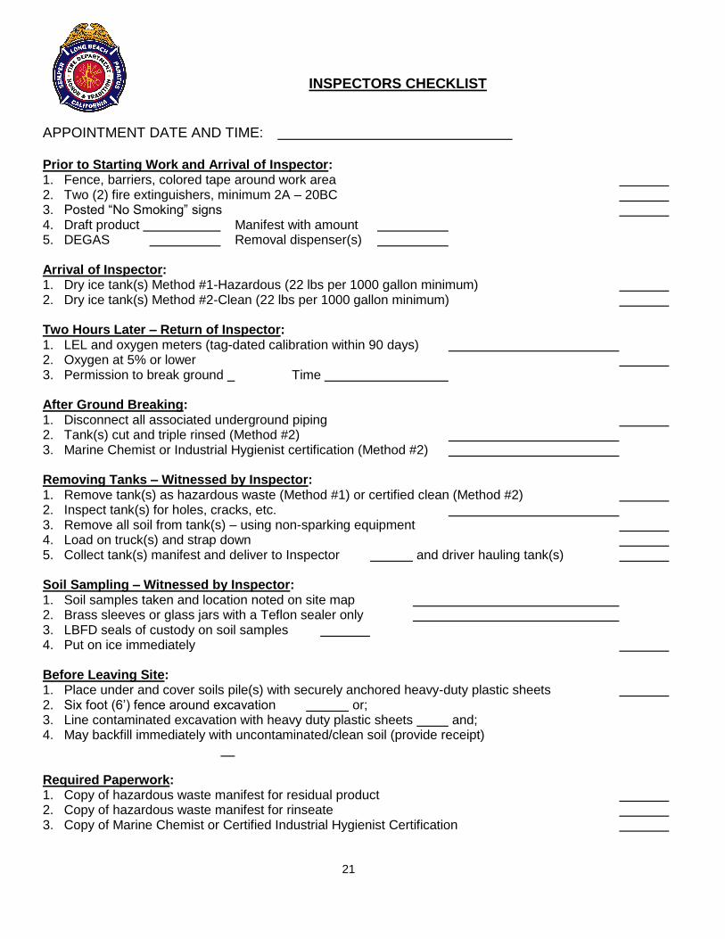
INSPECTORS CHECKLIST
APPOINTMENT DATE AND TIME: Prior to Starting Work and Arrival of Inspector: 1. Fence, barriers, colored tape around work area 2. Two (2) fire extinguishers, minimum 2A – 20BC 3. Posted “No Smoking” signs 4. Draft product Manifest with amount 5. DEGAS Removal dispenser(s) Arrival of Inspector: 1. Dry ice tank(s) Method #1-Hazardous (22 lbs per 1000 gallon minimum) 2. Dry ice tank(s) Method #2-Clean (22 lbs per 1000 gallon minimum) Two Hours Later – Return of Inspector: 1. LEL and oxygen meters (tag-dated calibration within 90 days) 2. Oxygen at 5% or lower 3. Permission to break ground Time After Ground Breaking: 1. Disconnect all associated underground piping 2. Tank(s) cut and triple rinsed (Method #2) 3. Marine Chemist or Industrial Hygienist certification (Method #2) Removing Tanks – Witnessed by Inspector: 1. Remove tank(s) as hazardous waste (Method #1) or certified clean (Method #2) 2. Inspect tank(s) for holes, cracks, etc. 3. Remove all soil from tank(s) – using non-sparking equipment 4. Load on truck(s) and strap down 5. Collect tank(s) manifest and deliver to Inspector and driver hauling tank(s) Soil Sampling – Witnessed by Inspector: 1. Soil samples taken and location noted on site map 2. Brass sleeves or glass jars with a Teflon sealer only 3. LBFD seals of custody on soil samples 4. Put on ice immediately Before Leaving Site: 1. Place under and cover soils pile(s) with securely anchored heavy-duty plastic sheets 2. Six foot (6’) fence around excavation or; 3. Line contaminated excavation with heavy duty plastic sheets and; 4. May backfill immediately with uncontaminated/clean soil (provide receipt) Required Paperwork: 1. Copy of hazardous waste manifest for residual product 2. Copy of hazardous waste manifest for rinseate 3. Copy of Marine Chemist or Certified Industrial Hygienist Certification
21

REMOVAL METHOD #1 – HAZARDOUS
The tank is removed from the ground and transported without being cleaned. The tank(s) must be “manifested,” transported as a “hazardous waste” and must be removed to a recognized TSD facility by a Licensed Hazardous Waste Transporter, subject to all applicable governmental regulations. Prior to starting work: 1. Barriers, caution tape and “No Smoking” signs shall be posted in order to keep any source of
ignition at least 25’ away from the excavation. 2. A Long Beach Fire Department Inspector must be on site to witness the dry ice procedure.
Place a minimum of twenty-two (22) pounds of dry ice per 1000 gallons of capacity in the tank.
3. Within two hours after dry icing the tank(s), a Long Beach Fire Department Inspector will return to the site and witness the contractor take oxygen content readings.
Oxygen content of the tank atmosphere shall be below 5 percent, at
which point the tank shall be considered inerted. (NFPA 306) It is mandatory that a properly calibrated flammable/combustible gas
analyzer and oxygen indicator, certified within 90 days, is on the job site from start to finish.
4. Work may begin only when permission is given by the Fire Inspector. Excavate and expose
top of tank. Identify all piping associated and relative to the tank. Disconnect the piping from the tank (including vent lines, associated piping, electrical lines and in-tank pump(s)) making observations for any product leakage. CONTINUOUS SUPERVISION MUST BE MAINTAINED DURING THE OPERATIONS BY A COMPETENT AND RESPONSIBLE ADULT EMPLOYEE OF THE CONTRACTOR NAMED ON THE REMOVAL PERMIT.
5. When more than 24 hours has elapsed since icing of tank, re-inert the tank with a minimum of twenty-two (22) pounds of dry ice per 1000 gallons of capacity. Two hour waiting period and/or reduced oxygen level of the tank atmosphere shall apply (see Step #3 above).
6. Plug all tank openings with threaded fittings. One fitting must be reduced and vented to ½”. 7. With a Long Beach Fire Department Inspector on-site, lift each tank from the excavation,
remove all external dirt with non-sparking tools and secure it on an appropriate transporting vehicle. The tank(s) must be placed on the vehicle with the opening at the top.
8. Prepare a Uniform Hazardous Waste Manifest and transport the tank(s) to a recognized TSD facility, subject to all applicable governmental regulations. A photocopy of this manifest must be given to the Fire Inspector before the tank leaves the site.
9. Soil samples from beneath the dispensers, pipes, tank(s) and spoil piles will be required and witnessed by a Long Beach Fire Department Inspector. Follow sampling guidelines required by Long Beach Department of Health & Human Services (LBDHHS) under Appendix A.
22
REMOVAL METHOD #2 – CLEAN
Each tank is cleaned “on-site”, “certified” by a certified Marine Chemist (or certified Industrial Hygienist) as clean, vapor free. The cleaned tank(s) can be transported (with their respective certifications) for material recycling or salvage. Prior to starting work: 1. Barriers, caution tape and “No Smoking” signs shall be installed to keep any source of
ignition at least 25’ away from the excavation. 2. A Long Beach Fire Department Inspector must be on-site to witness the dry ice procedure.
Place a minimum of twenty-two (22) pounds of dry ice per 1000 gallons of capacity into the tank.
3. Within two hours after dry icing the tank(s), a Long Beach Fire Department Inspector will
return to the site and witness the contractor take oxygen content readings. Oxygen content of the tank atmosphere shall be below 5 percent, at
which point the tank shall be considered inerted. (NFPA 306) It is mandatory that a properly calibrated flammable/combustible gas
analyzer and oxygen indicator, certified within 90 days, is on the job site from start to finish.
4. Work may begin only when the Fire Inspector gives permission. Excavate and expose top of
tank. Identify all piping associated and relative to the tank. Disconnect the piping from the tank (including vent lines, associated piping, electrical lines and in-tank pump(s)) making observations for any product leakage. CONTINUOUS SUPERVISION MUST BE MAINTAINED DURING THE OPERATIONS BY A COMPETENT AND RESPONSIBLE ADULT EMPLOYEE OF THE CONTRACTOR NAMED ON THE REMOVAL PERMIT.
5. Use vacuum truck equipment following bonding procedures. TAKE FREQUENT LEL
READINGS). 6. Water blast the tank interior using a minimum of 2000 psi of water and detergent, if necessary
(other cleaning methods as per NFPA #327 may be presented with this application). Loose scale, sludge and rinse water are removed by the vacuum truck. The washing may cease when the sludge and debris is removed and the LEL is 0%. Grounding and bonding procedures shall be followed with water blasting equipment.
7. Interior rinse water and sludge shall be manifested and transported to a fully approved and
permitted TSD facility by a Licensed Hazardous Waste Transporter, subject to all applicable governmental regulations. A copy of the manifest shall be given to the Long Beach Fire Inspector on-site before tank is removed.
23
REMOVAL METHOD #2 – CLEAN (Continued)
8. A certified Marine Chemist or a certified Industrial Hygienist shall inspect the tank and issue a
certificate stating that the tank is clean and vapor free. Copies of the certification for each tank must be given to the Long Beach Fire Inspector on the site.
NO HOT WORK IS PERMITTED ON ANY TANK 9. The Marine Chemist or Industrial Hygienist shall apply an identification number that
corresponds to the “certification” with a can of spray paint to the tank exterior. A copy of the certification must be kept with the tank.
10. If no manhole is in the tank, a pneumatic cold cutting tool shall be used to cut a 12” x 12” hole
(minimum) at an appropriate location to facilitate interior inspection. Use only beryllium or approved non-sparking tools. Large tank(s) may require multiple manholes since all interior areas of the tank must be visible for inspection. LEL readings shall be 0% before cutting begins.
11. In the presence of the Long Beach Fire Department Inspector remove the cleaned tank from
the excavation. Remove all soil from tank exterior with non-sparking tools. 12. Load and secure the tank(s) on appropriate transporting equipment and remove with
certificate(s) from premises. The tank(s) may be transported, with certifications, to a material recycling or salvage business.
13. Soil samples from beneath the dispensers, pipes, spoil piles and tank(s) will be required and
witnessed by a Long Beach Fire Department Inspector. Soil sampling requirements must be in accordance with the Long Beach Department of Health and Human Services guidelines listed in Appendix A. Additional soil sampling may be required at the discretion of the discretion of the Long Beach Fire Department , Bureau of Fire Prevention Inspector.
NOTE: Complying with the requirements of the Long Beach Fire Department does not preclude
the necessity to comply with regulations of other authorities and licensing agencies.
24

CLOSURE IN-PLACE Closure in-place shall be allowed only under the following conditions: 1. A Licensed Structural Engineer determines that removal of the underground storage tank(s)
would affect the integrity of an adjacent structure or would create a significant safety hazard by removing said tank from its current location.
2. Plans are to be submitted to the Long Beach Fire Department/Bureau of Fire Prevention,
Underground Storage Tank Section affixed with the seal and signature of the above engineer, and a formal letter requesting closure in place with reasons specified. Letter shall be signed. These plans and documents shall meet Federal, State, and local requirements. Plan submittal shall take place at City Hall Development Services Counter.
3. Formal inspections and soil sampling shall be witnessed by the Long Beach Fire
Department/Bureau of Fire Prevention, Underground Storage Tank Section Inspector. 4. A Soil Sampling Report should include all applicable information in Appendix A before it is
submitted to the Long Beach Department of Health and Human Services (LBDHHS), Bureau of Environmental Health, Hazardous materials Division. It must be submitted within 14 days of sampling.
Upon review of the Soil Sampling Report, the LBDHHS will determine if the excavated soil may be placed back into the excavation. After July 1, 2013, the LBDHHS will refer to the Los Angeles Regional Water Quality Control Board, underground storage tank cases upon confirmation that an unauthorized release has impacted the soil at the site, based on the review of the Soil Sampling Report. Projects related to above ground storage tank, hydraulic lift and clarifier will continue to be handled by the LBDHHS.
25

TANK INSTALLATION
26
INSTALLATION OF UNDERGROUND STORAGE TANKS
POLICY Underground storage tanks regulated by the Long Beach Fire Department shall be installed in accordance with Title 23, Division 3, Chapter 16, Article 3 “New Underground Storage Tank Construction and Monitoring Standards,” California Code of Regulations and the currently adopted California Fire Code. Underground hazardous storage tank(s) and/or systems constructed in the City of Long Beach must conform to standards issued by the Long Beach Fire Department, Bureau of Fire Prevention. Written approval must be obtained from this Department prior to the installation of any underground storage tank(s). The applicant must show that the proposed site, existing soil and groundwater conditions are suitable for the construction of the proposed storage system. Prior to commencement of work, the person responsible for the installation of underground tanks must apply for and obtain all necessary permits/licenses. Such additional requirements not otherwise mentioned herein, may include, but are not limited to: State of California, Division of Occupational Safety and Health, Trenching/Excavation Permit; valid Crane Certification; California Fire Code Requirements, Long Beach Municipal Code Requirements, and any plan approvals necessary from the Long Beach Development Services Division. The Long Beach Fire Department requires a minimum of four on-site construction inspections. Inspections must be scheduled three (3) working days prior to the inspection date.
First Inspection – Setting the Tank(s). Witness holiday, pressure or other appropriate test for field acceptance. Verify U.L. Number(s), etc. See Section Article 3,2631(b) or CCR Title 23, Division 3, Chapter 16. Second Inspection – Primary Piping. Observe a 30 minute pressure test and soap test of all joints and connections. See page 34 for piping test pressure requirements. Third Inspection – Secondary Piping. Observe a 30-minute pressure test at no less than 5 psi and soap test of all joints and connections. The 5 psi test may be changed to manufacturers recommended test pressure with proper documentation. See page 34 for piping test pressure requirements. Fourth Inspection – Final. Full system inspection with product in tanks. Monitoring system test for alarm, leak detection and positive shutdown. All signs and placards in place. All construction, painting, etc. complete and facility ready to open after inspection. California Fire Code service station inspection. (See page 39-42)
27
CERTIFICATION Owners or their agents shall use State of California, State Water Resources Control Board and Certificate of Compliance Form C to certify that the underground storage tank(s) and piping were installed property. (See forms section of this document.)
OVERVIEW – NEW INSTALLATION All new underground storage tank installations are subject, but not limited, to all of the following: 1. New – U.L. approved double wall underground storage tanks. Fiberglass reinforced
plastic or steel clad with fiberglass reinforced plastic underground storage tanks are the only approved installations.
2. Tanks shall be double wall and provide primary and secondary levels of containment. 3. Tanks shall have a continuous monitoring system with audible and visual alarm, which will
provide positive turbine shut down of product when leak is detected. 4. All piping, including vents and vapor recovery shall have secondary containment. 5. Piping shall have a continuous monitoring system with audible and visual alarm which will
provide positive turbine shutdown when leak is detected. 6. Approved fill tubes and spill containment buckets are required at each tank fill point. 7. Approved overfill prevention is required in each tank. The overfill prevention shall provide
positive shut-off of flow when the tank is filled to no more than 95 percent. 8. Approved product containment boxes are required under each dispenser and will have
floats to shutdown dispenser or sensors, which will provide positive turbine shutdown. 9. All dispensing devices shall be protected against physical damage from vehicles by
mounting on a concrete island a minimum of 6 inches in height. Long Beach Municipal Code 18.48. FLUSH MOUNTED DISPENSERS ARE NOT ALLOWED.
10. Man ways – Manholes – Sumps – All new underground storage tanks shall be equipped
with dual sumps. 11. Shut-off Impact Value – An approved emergency shut-off impact valve incorporating a
fusible link designed to close automatically and contain liquid on both sides of the shear section.
12. Plan approval for Electrical Installations – In the City of Long Beach, all electrical
installations shall be approved by the Development Services Division. 13. Crash Posts shall be provided. See Long Beach Municipal code for criteria, (18.48).
28

AUTOMATIC TANK GAUGE ALL single walled fiberglass underground storage tanks must be equipped with an automatic tank gauge which will generate a hard copy of the calculated leak rate and leak threshold. Monthly Automatic Tank Gauge (ATG) reports and/or Continuous Statistical Leak Detection (CSLD) must be kept on site for review by Long Beach Fire Department inspector.
DUAL WALL TANKS WITHOUT STRIKER PLATE Section 2662.(d) by December 22, 1998, owners shall install a wear plate (striker plate) which meets the criteria in Section 2631(c) under all tank openings that could be used for manual dip sticking. A drop tube-mounted bottom protector may fulfill this requirement. An automatic tank gauge will satisfy the above requirement.
29

UNDERGROUND STORAGE TANK INSTALLATION REQUIREMENTS
A. CONSTRUCTION STANDARDS 1. Containment
All new underground storage tanks, including all associated piping used for the storage of hazardous substances, shall be U.L. approved and have primary and secondary levels of containment.
2. Identifying Markings The exterior surface of underground storage tanks shall bear a marking, code stamp or
label showing the following minimum information:
a. Engineering standard used; b. Nominal diameter in feet; c. Nominal capacity in gallons; d. Degree of secondary containment; e. Usable capacity in gallons; f. Design pressure in PSIG; g. Maximum operating temperature in degrees Fahrenheit; h. Construction materials; i. Year manufactured; j. Manufacturer k. UL
1. Man ways – Manholes – Sumps
All new underground storage tanks shall be equipped with dual sumps. One sump shall
be provided at pump and fill. Each sump shall be equipped with a leak monitor capable of providing positive turbine shutdown.
B. SECONDARY CONTAINMENT
1. The secondary containment system shall be constructed to contain at least 100 percent
of the usable capacity of the primary containment system. 2. A vault as a secondary containment system shall be designed and constructed
according to an Engineering Specification approved by a State Licensed Engineer or according to a nationally recognized industry code or engineering standard.
30

C. MONITORING REQUIREMENTS
1. Interstitial space shall utilize one or more of the following monitoring methods:
a. Liquid level indicator. b. Hazardous substance sensor. c. Vapor monitor. d. Pressure or vacuum loss detector.
2. The interstitial space of the underground storage tank shall be monitored using
continuous monitoring system. 3. The continuous monitoring system shall be connected to an audible and visual alarm
system, which will provide positive turbine shut down as approved by the local agency. DISCRIMINATING SENSORS Leak sensors, which activate only when in contact with motor vehicle fuels (gasoline or
diesel fuels), shall not be used in any areas requiring leak sensors or monitoring.
D. UNDERGROUND PIPING WITH SECONDARY CONTAINMENT 1. All underground piping shall have secondary containment and be equipped and
monitored as follows:
a. The secondary containment system shall be equipped with a continuous monitoring system which is connected to an audible and visual alarm system capable of providing positive turbine shut down, and
b. Automatic line leak detectors shall be installed on underground pressurized
piping and shall be capable of detecting a three gallon per hour leak rate at 10 psi within 1 hour with a probability of detection of at least 95 percent and a probability of false alarm no greater than 5 percent.
E. ALL MONITORING PROGRAMS (See page 37-38)
All monitoring programs shall include the following: 1. A written routine monitoring procedure, which establishes:
a. The frequency of performing the monitoring method; b. The methods and equipment to be used for performing the monitoring; c. The location(s) where the monitoring will be performed; d. The name(s) and title(s) of the person(s) responsible for performing the
monitoring and/or maintaining the equipment; e. The reporting format; f. The preventive maintenance schedule for the monitoring equipment. The
maintenance schedule shall be in accordance with the manufacturer’s instructions; and
31
g. A description of the training needed for the operation of both the tank
system and the monitoring equipment. 2. A response plan which demonstrates that any unauthorized release will be removed
from the secondary containment system within the time consistent with the ability of the secondary containment system to contain the hazardous substance, and shall include, but is not limited to, the following:
a. A description of the proposed methods and equipment to be used for removing and
property disposing of any hazardous substances, including the location and availability of the required equipment if not permanently on-site, and an equipment maintenance schedule for the equipment located on-site.
b. The name(s) and title(s) of the person(s) responsible for authorizing the work necessary under the response plan.
(Authority: Health and Safety Code 25299.3, 25299.7, Reference: Health and Safety Code 25281, 25291, 40 CFR 280.20)
F. LEAK INTERCEPTION AND DETECTION SYSTEM 1. The leak interception and detection system shall prevent the contact of any leaked
hazardous substance with ground water. At a minimum, the leak interception and detection system shall be above the highest anticipated ground water elevation. Proof that the leak interception and detection system will protect ground water must be demonstrated by the owner of the underground storage tank to the satisfaction of the Long Beach Fire Department, Bureau of Fire Prevention. In determining whether the leak interception and detection system will adequately protect ground water, provide at a minimum, the following:
a. The containment volume of the leak interception and detection system; b. The maximum leak, which could go undetected under the monitoring method
and the maximum period during which the leak could go undetected. c. The frequency and accuracy of the proposed method of monitoring the leak
interception and detection system; d. The depth from the bottom of the leak interception and detection system to the
highest anticipated level of ground water; e. The nature of the unsaturated soils under the leak interception and detection
system and their ability to absorb contaminants or to allow movement of contaminants;
f. The effect of any precipitation or subsurface infiltration on the movement of any leak of hazardous substance and the available volume of the leak interception and detection system; and
g. The nature and timing of the response plan to clean up any hazardous substances, which have been discharged from the primary container.
(Authority: Health and Safety Code 28299.3, 25299.7, Reference: Health and Safety Code 25281, 25291, 40 CFR 280.20)
32
G. INSTALLATION AND TESTING REQUIREMENTS FOR NEW UNDERGROUND STORAGE TANKS AND PIPING
Primary and secondary containment systems shall be designed, constructed, tested
and certified to comply, as applicable with all of the following requirements:
1. All underground storage tanks shall be tested at the factory before being transported in accordance with the applicable sections of the industry code or engineering standard under which they are built.
2. Before installation, the underground storage tank shall be tested for tightness at the
installation site in accordance with the manufacturer’s written guidelines. 3. All other secondary containment systems shall pass a post-installation test, which
meets the approval of the local agency. 4. Testing Containment Box (Tank Sump and Dispenser Pan).
a. After piping installation and prior to backfilling, each containment box shall be water tested.
b. This water test shall consist of filling the containment box with water to a level 1”
below the top of the containment box. (This test should have a duration of 24 hours minimum) and shall be observed by the Fire Department inspector when testing the secondary containment piping.
5. After installation, but before the underground storage tank is placed in service, a
tank integrity test shall be performed to ensure that no damage occurred during installation.
6. All underground storage tanks shall be installed according to a code of practice
developed in accordance with voluntary consensus standards and the manufacturer’s written installation instructions. The owner or operator shall certify with State Form C, that the underground storage tank has been installed in accordance with the requirements in Section (K).
7. All underground storage tanks 12,000 gallons or larger, or any tank subject to
flotation shall be anchored. Conformation of mean high levels of ground water shall show minimum of 20 feet below tank bottom and high water table. This shall be provided through LA County Hydrology Department.
H. All underground piping shall be UL approved for the proposed fluid(s) and shall be
protected against corrosion. Underground piping shall meet all of the following requirements:
33

1. All underground primary piping in contact with hazardous substances under normal operating conditions shall be installed inside a secondary containment system, which may be a secondary pipe. All secondary containment systems shall be sloped so that all releases will flow to a collection sump located at the low point of the underground piping. Pipe fall shall be field confirmed in presence of LBFD Inspector to be at least 1/8” per foot. Contractor shall provide a calibrated smart digital level for this purpose. Piping shall be bedded with joints exposed for soaping.
2. Primary piping and secondary containment systems shall be installed in accordance with a code of practice developed in accordance with voluntary consensus standards. The owner or operator shall certify that the piping is installed in accordance with the above requirements as required by Section (L).
3. All new primary piping and secondary containment systems shall be tested for tightness after the installation in accordance with the manufacturer’s guidelines. As a minimum, the primary piping shall be tested for tightness hydrostatically at 150 percent of designed and operating pressure or pneumatically at 110 percent of design pressure. If the calculated test pressure is less than 40 psi, 40 psi shall be used as the test pressure. The pressure shall be maintained for a minimum of 30 minutes and all joints shall be soap tested. A failed test, as evidenced by presence of bubbles shall require appropriate repairs and a retest. To assure accuracy of all gauges used for testing, inspector shall witness gauges zeroed at completion of inspection. All gauges shall zero.
Provide manufacturers cut sheets for piping and pumps with your submittal. Provide certification for pipe installers.
4. Underground pressurized piping which meets all of the following requirements satisfies the annual tightness test requirement specified in subsection 2636(g) of the Health and Safety Code:
a. The secondary containment system is equipped with a continuous monitoring system. The leak detection device can be located at the pump sump.
b. A continuous monitoring system is connected to an audible and visual alarm system and the pumping system.
c. The pumping system shuts down automatically if the continuous monitoring system fails or is disconnected. This requirement does not apply to the emergency generator system if the site is manned.
5. As a Reminder: ALL underground piping shall have secondary containment, including VENTS and VAPOR RECOVERY.
I. SHUT-OFF IMPACT VALUE
An approved emergency shut-off impact valve incorporating a fusible link designed to close automatically and contain liquid on both sides of the shear section in the event of severe impact or fire exposure shall be rigidly mounted and connected by a union in the dispensing supply line at the base of each dispensing device. The shear section of the impact valve shall be mounted flush with or within ½ inch of the top of the surface upon which the dispenser is mounted. Vapor recovery shear valves are also required.
34
J. SPILL CONTAINER AND OVERFILL PREVENTION All underground storage tanks shall be equipped with a spill container and an overfill
prevention system as follows: 1. The spill container shall collect any hazardous substances spilled during tank filling
operations to prevent the hazardous substance from entering the subsurface environment. The spill container shall meet the following requirements:
a. The exterior wall must be protected from galvanic corrosion if made of metal. b. It must have a minimum capacity of five gallons (19 liters).
2. The overfill prevention system shall not allow for manual override and shall provide
positive shut-off of flow when the tank is filled to no more than 95 percent. The system may include the following:
a. Transfer operator alert when the tank is 90 percent full by restricting the flow
into the tank or triggering an audible and visual alarm; or b. Restrict delivery of flow to the tank at least 30 minutes prior to tank overfill,
provided the restriction occurs when the tank is filled to no more than 95 percent of capacity and provide audible alarm at least five minutes prior to overfill.
3. Owners and operators must use care to prevent releases due to spilling or
overfilling. The owner and operator must insure that the volume available in the tank is greater than the volume of product to be transferred to the tank before the transfer is made and that the transfer operation is monitored constantly to prevent overfilling or spilling.
K. FUEL DISPENSER CONTAINMENT BOXES Containment boxes must be installed underneath all fuel dispensers. Containment
boxes must be anchored to the concrete and must be capable of capturing leaking product under the dispensers.
Containment boxes must meet the following specifications: 1. They must be a solid unit that does not allow any product to escape outside the
containment box or unit. 2. They must be capable of activating the shear valve or provide positive shut down
and alarm after a maximum of 5 oz. of product has been captured. 3. All metallic flex lines shall terminate inside a secondary containment area; tank
sump and dispenser containment shall be electronically monitored. Containment box shall be constructed of a non-metallic non-corrosive material.
35

L. CERTIFICATION Owners or their agents shall certify that the installation of underground storage tanks
and piping meets all of the following conditions: 1. The installer has been adequately trained and certified by the tank and piping
manufacturers. 2. The installer has been certified or licensed by the Contractors State License Board. 3. The underground storage tank and primary piping, and any secondary containment
was installed, according to applicable voluntary consensus standards, and any manufacturer’s written installation instructions.
4. All work listed in the manufacturer’s installation checklist has been completed. 5. The installation has been inspected and approved by the local agency, or, if
required by the local agency inspected and certified by a registered professional engineer who has education in, and experience with underground storage tank system installation.
36

Date ____________________
WRITTEN MONITORING PROCEDURES UNDERGROUND STORAGE TANK MONITORING PROGRAM
This monitoring program must be kept at the UST location at all times. The information on this monitoring program are conditions of the operating permit. The permit holder must notify the LONG BEACH FIRE DEPARTMENT within 30 days of any changes to the monitoring procedures, unless required to obtain approval before making the change. (Required by Sections 2632(d) and 2641(h) CCR) Facility Name
Facility Address
A. Describe the frequency of performing the monitoring: Tank Piping
B. What methods and equipment, identified by name and model, will be used for performing the monitoring:
Tank Piping
C. Describe the location(s) where the monitoring will be performed (facility plot plan should be attached):
D. List the name(s) and title(s) of the people responsible for performing the monitoring and/or maintaining the equipment:
E. Reporting format for monitoring: Tank Piping
F. Describe the preventive maintenance schedule for the monitoring equipment. Note: Maintenance must be in accordance with the manufacturer’s maintenance schedule, but not less than every 12 months.
G. Describe the training necessary for the operation of UST system, including piping and
the monitoring equipment:
37

Date ____________________
EMERGENCY RESPONSE PLAN UNDERGROUND STORAGE TANK MONITORING PROGRAM
This monitoring program must be kept at the UST location at all times. The information on this monitoring program are conditions of the operating permit. The permit holder must notify the LONG BEACH FIRE DEPARTMENT within 30 days of any changes to the monitoring procedures, unless required to obtain approval before making the change. (Required by Sections 2632(d) and 2641(h) CCR) Facility Name Facility Address 1. If an unauthorized release occurs, how will the hazardous substance be cleaned up?
Note: If released hazardous substances reach the environment, increase the fire or explosion hazard, are not cleaned up from the secondary containment within 8 hours, or deteriorate the secondary containment, then the LONG BEACH FIRE DEPARTMENT must be notified within 24 hours.
2. Describe the proposed methods and equipment to be used for removing and properly
disposing of any hazardous substances: 3. Describe the location and availability of the required cleanup equipment in Item 2 above: 4. Describe the maintenance schedule for the cleanup equipment: 5. List the name(s) and title(s) of the person(s) responsible for authorizing any work
necessary under the response plan:
38
LONG BEACH FIRE DEPARTMENT BUREAU OF FIRE PREVENTION
3205 LAKEWOOD BLVD. LONG BEACH, CA 90808
(562) 570-2560
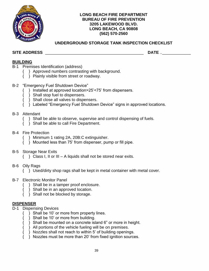
UNDERGROUND STORAGE TANK INSPECTION CHECKLIST SITE ADDRESS DATE .. BUILDING B-1 Premises Identification (address) { } Approved numbers contrasting with background. { } Plainly visible from street or roadway. B-2 “Emergency Fuel Shutdown Device” { } Installed at approved location>25’<75’ from dispensers. { } Shall stop fuel to dispensers. { } Shall close all valves to dispensers. { } Labeled “Emergency Fuel Shutdown Device” signs in approved locations. B-3 Attendant { } Shall be able to observe, supervise and control dispensing of fuels. { } Shall be able to call Fire Department. B-4 Fire Protection { } Minimum 1 rating 2A, 20B:C extinguisher. { } Mounted less than 75’ from dispenser, pump or fill pipe. B-5 Storage Near Exits { } Class I, II or III – A liquids shall not be stored near exits. B-6 Oily Rags { } Used/dirty shop rags shall be kept in metal container with metal cover. B-7 Electronic Monitor Panel { } Shall be in a tamper proof enclosure. { } Shall be in an approved location. { } Shall not be blocked by storage. DISPENSER D-1 Dispensing Devices { } Shall be 10’ or more from property lines. { } Shall be 10’ or more from building. { } Shall be mounted on a concrete island 6” or more in height. { } All portions of the vehicle fueling will be on premises. { } Nozzles shall not reach to within 5’ of building openings. { } Nozzles must be more than 20’ from fixed ignition sources.
39

D-2 Special Type Dispenser { } Remote preset type shall have an attendant on duty. { } Shall be in clear view of attendant. { } Attendant shall be able to communicate with persons at all times. D-3 Signs – Conspicuously Posted Within Sight of Each Dispenser { } Prohibiting smoking. { } Prohibiting dispensing in unapproved containers. { } Requiring vehicle engines to be stopped during fueling. D-4 Dispenser { } Shall have current LA County weights and measure sticker on each dispenser. D-5 Nozzles { } Shall be a listed automatic closing type. { } Shall be equipped with an integral latch open devise. { } Shall close automatically if pressure is lost. (Test annually.) { } Shall be designed to be retained in the fill pipe during fueling. D-6 Listed Equipment { } Tanks, electrical equipment, dispensers, hoses, nozzles and pumps shall be
listed, (i.e. U.L. approved). D-7 Dispenser Containment Box { } Shall be installed under each dispenser. { } Shall have an approved leak detection device for 5 oz or more liquid. Sensors
shall be sleeved. { } Shall be able to hold a minimum of 5 gals OR { } May be electronically monitored to shut down pumps positively when a leak has been detected. D-8 Shear Valves { } An approved emergency shut-off impact valve with a fusible link shall be
mounted flush or within ½ inch of the top of the surface on which the dispenser is mounted.
{ } Multiple shear valves are required on multi-product dispensers.
TANK T-1 Testing of Leak Detection Devices { } Shall be done annually by the owner or operator. { } Test results shall be maintained on the premises.
T-2 Leak Detection { } Shall be continuous electronic monitoring system. { } Shall be automatic line leak detectors.
T-3 Overspill Bucket { } Shall be in each fill pipe. { } Shall have a capacity of not less than 5 gals. { } Shall have a drain valve which drains into primary tank. { } Shall be kept clean of all debris.
40

T-4 Overfill Device { } All be an audible and visual device that activates when the tank reaches 90% of
capacity. Shall be visible from driver’s delivery point. { } Shall be a positive shut-down device which automatically shuts off filling at 95%
of tank capacity. T-5 Drop Tubes { } Must be installed to within 6” of the bottom of the tank. T-6 Probes { } Shall be placed in the tanks interstitial space. { } Shall be in the tank(s) sumps. { } Shall be connected to an audible and visual alarm system with positive shut-
down. { } Shall be non-discriminating sensor. DOCUMENTS P-1 “A” Forms { } Must be complete for each site – do not use “UNKNOWN” – Leave Blank. P-2 “B” Forms { } Must be complete for each tank including split tanks compartment. P-3 “C” Forms { } Must be complete for installations. P-4 “D” Forms - Written Routine Monitoring Program { } Must be completed. Document contained within. P-5 Emergency Response Plan for Unauthorized Release { } Must be completed. Document contained within. P-6 “E” Forms -Financial Responsibility { } Must be complete. P-7 Business Emergency Plan { } Must be complete. P-8 Tank Integrity Test – Required Before Placing in Service Either: { } Tank integrity test OR { } Interstitial monitor certified to perform a tan integrity test. P-9 Vapor Return Piping { } Dispensing devices incorporating vapor recovery shall be listed and labeled. { ) Descriptions of parts and method of installation shall be included in the report. P-10 Inventory Control { } Accurate daily records showing by product reconciliation between sales, use,
receipts and inventory on hand shall be maintained and kept on the premises. { } Any consistent loss shall be reported.
41

P-12 Permits { } Issued by local agency shall be displayed. P-13 Business License { } Must be displayed Sec.3.80.421.5 OWNER/AGENT INSPECTOR DATE
42
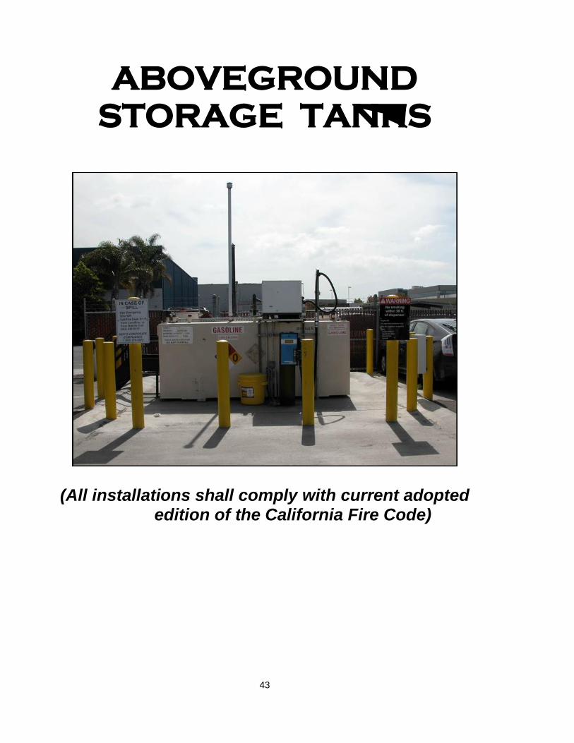
ABOVEGROUND
STORAGE TANKS
(All installations shall comply with current adopted edition of the California Fire Code)
43

APPENDIX A
44

POST TANK REMOVAL GUIDELINES
After July 1, 2013, the LBDHHS will refer to the California State Water Resources Control Board
(SWRCB), underground storage tank cases upon confirmation that an unauthorized petroleum* release has impacted the soil or groundwater. The referral is based upon the review of the Soil Sampling Report and confirmation that an unauthorized release has occurred at the subject site On the other hand, if an unauthorized release has not occurred, the LBDHHS will notify all stake holders that further sampling will not be required. The criteria use to determine if a release has occurred is specified in the SWRCB’s Low Threat Underground Storage Tank Case Closure Policy, adopted by State Water Board Resolution No. 2012-0016 (effective August 17,2012). Non-UST projects, related to above ground storage tanks, hydraulic lifts and clarifiers, will continue to be managed by the LBDHHS. If the soil or groundwater is determined to become impacted by an unauthorized release of, additional characterization will be necessary.
* Petroleum is defined as crude oil, or fraction thereof, which is liquid at standard conditions of temperature
and pressure, which means 60 degrees Fahrenheit and 14.7 pounds per square inch absolute, including the following substances: Motor fuels, jet fuels, distillate fuel oils, residual fuel oils, lubricants, petroleum solvents and used oils, including any additives and blending agents such as oxygenates contained in the formulation of substances.
The location(s) from which soil samples are to be taken are specific to the type of project. They may be taken from beneath the tank(s), dispensers or pipes and always from soils piles. Samples must be taken 2 to 4 feet below the tank invert, the product lines (at 20 foot intervals). A Long Beach Fire Department Inspector witnessed the sampling. If groundwater is encountered, grab water samples must be obtained from a Hydropunch TM or similar type of system and properly analyzed. Because these sample results are not repeatable, they will be considered qualitative measurements. Also, the results will determine if the water is to be disposed of as hazardous waste.
Accepted sampling methods are: Split-barrel core sampler, modified California sampler, Shelby Tube, or other accepted method. To preserve and minimize organic losses, the EPA Method 5035 specified in USEPA SW- 846, version (April 1998), or subsequent edition is to be used.
Soil sampling must be done under the direct supervision of a California Professional Geologist (PG). Excavated soil must be handled in compliance with the South Coast Air Quality Management District's Rule 1166 regarding volatile organic compound (VOC) emissions from contaminated soil.
Analytical tests must be performed by a laboratory with certification under the California environmental laboratory Accreditation (ELAP). Analytical tests for the soil samples are indicated on pages 4 and 5 under Laboratory Analyses. A Soil Sampling Report can be found starting on page 46. This report must be submitted to City of Long
Beach Department of Health and Human Services (LBDHHS) within 14 days of sampling. Upon review of 45
the Soil Sampling Report, the LBDHHS will determine if the excavated soil may be placed back into the excavation. The excavation may be immediately backfilled with uncontaminated imported soil, even before the Soil Sampling Report is available. Receipts must be available to the LBFD and the LBDHHS as proof that the soil is uncontaminated (clean). The LBDHHS does not stipulate how long an excavation can remain open as long as precautions have been taken by the responsible party to assure the avoidance of any potential public danger.
All stockpiles shall be on and covered with heavy duty, continuous plastic sheet(s) joined at the seams and securely anchored to prevent any exposure of soil to the atmosphere. The site shall be temporarily fenced to a height of six feet. If an excavation is left in an unsafe condition, the property will be returned to a safe condition by the City of Long Beach and all costs incurred will be charged to the owner/permitee.
Within 30 days of tank removal, a Final Tank Removal Report (see page 47 for requirements and format) and a check for the project review fee must be mailed to the City of Long Beach Department of Health and Human Services, Division of Hazardous Materials: 2525 Grand Avenue, Suite 222, Long Beach, CA 90815. (Call 562-570-4129 for the current UST Removal Report Review fee)
Sampling Report The Soil Sampling Report is a preliminary assessment, through documentation, of the subsurface conditions from the open excavation where a tank was removed. It is considered the minimum documentation required before the backfilling of an open excavation, therefore the following must be provided. 1. SlTE HYDROGEOLOGY: a. Indicate depth to groundwater, aquifer system and local use of groundwater. 2. SOIL SAMPLING: Samples are to be collected using a volumetric sampling system designed to collect, store and deliver a soil sample. To preserve and minimize organic losses, EPA Method 5035 specified in USEPA SW-846, version (April 1998) or subsequent version is to be used. Samples must be tested by a laboratory with certification under the California Environmental Laboratory Accreditation program (ELAP). 3. SITE GEOLOGY: a. Submit cross-section of subsurface discovered during tank excavation. b. Describe soil lithology. 4. SOIL TEST RESULTS 5. MANIFESTS a. Tank disposal. Certification by Marine Chemist or Industrial Hygienist) b. Rinseate disposal. c. Contaminated soil disposal.
6. CONCLUSIONS a. Recommend any additional work (site characterization.). b. Recommend no additional work (closure) 7. SIGNATURE/STAMPS REQUIRED FROM ONE OF THE FOLLOWING: a. California Professional Civil Engineer (PE). b. California Professional Geologist (PG).
46
FINAL TANK REMOVAL REPORT 1. Tank Information a. Date tank(s) removed and contents samples. b. Number of tanks removed. c. Stored product. d. Tank capacity. e. Age of tank. f. Tank construction material. g.Tank disposal documentation: Removal as hazardous waste (manifested), or as scrap metal (Certification by a Marine Chemist or Industrial Hygienist). h. Product disposal documentation: manifest if tank is destroyed to be rendered as scrap metal. 2. Tank Removal a. Describe removal procedure. b. Monitor excavated soil for air emissions to comply with SCAQMD rule 1166. 3. Site Plan a. Show location of -tanks, sampling points, building structures, piping and pumps. b. Show adjacent streets. c. North arrow. d. Area of excavation. 4. Soil Sampling Report (laboratory data and chain of custody attached to corresponding reports must be original). 5. Depth to groundwater must be provided and distance to the nearest drinking water well 6. Underground Storage Tank Unauthorized Release Report (Leak) / Contamination Site Report if it is
confirmed that the soil has been impacted 7. Names and mailing addresses and phone numbers for the following parties: person/entity who
financed the project; property owner; business operator.
8. A copy of the Final Tank Removal Report must be mailed to the Long Beach Fire Department at 3205 Lakewood Blvd, Long Beach, CA 90808.
47
LABORATORY ANALYSES PRODUCT or CONTAMINANT TEST METHOD SOIL WATER
Gasoline and MTBE BTXE
TPH= C4-C12 8260B
TPH= C4-C12 602
Diesel fuel TPH= C13-C22 8260B
TPH= C 13 -C22 602
Jet fuel TPH= C13 -C22 8260B
TPH= C13 -C22
Waste motor oil TPH= C23-C32 8260B CAM Metals
TPH= C23-C32 8260B CAM Metals
Solvent
Site Specific Site Specific
Pesticides
Site Specific Site Specific
Hydraulic Lift Vaults TPH= C23-32 8260B CAM Metals
TPH= C23-C3 8260B CAM Metals
Clarifiers TPH= C13-C32 8260B CAM Metals
TPH= C13-C22 8260B CAM Metals
Above –Ground Petroleum Tanks
TPH= C13-C32 8260B CAM Metals
TPH= C13-C22 8260B CAM Metals
Unknowns (Tank contents must be analyzed)
(Tank contents must be analyzed)
Refer to Table I for method detection limit (MDL) requirements. TEST METHODS 602 Aromatic volatile organics (water only) Cal-LUFT GCIFID C4-C12 C13-C22 C23+ 8021B Aromatic and halogenated (up to 3 carbons) volatile organics 8260B Volatile and halogenated organics
48

TABLE I: ANALYTICAL REQUIREMENTS
REQUIRED MDL
ANALYTE ANALYTICAL METHOD SOIL (µg/kg) WATER (µg/L)
BTEX EPA Method 8260B (8021B) 1 0.5
MTBE EPA Method 8260B 2 1 DlPE EPA Method 8260B 2 1
ETBE EPA Method 8260B 2 1 TAME EPA Method 8260B 2 1 TBA EPA Method 8260B 20 I0
TPHg Cal-LUFT GC/FID or GC/MS 100-200 50-1 00
TPHd Cal-LUFT GC/FID 1,000 500 Methanol Cal-LUFT GC/FlD 1,000 500
Ethanol Cal-LUFT GC/FID (EPA8260B) 500 250
Source: California Regional Water Quality Control Board, Los Angeles Region, UST Lab Requirements For Oxygenates (09/06)
Report any concentration detected between the method detection limit (MDL) and estimated quantification limit (EQL) or reporting limit (RL) in a numerical value with a "J" flag indicator. All "Non-Detect" (ND) shall be reported in a format with "< (numerical MDL)." Integrate all fuel oxygenate additive concentration into total petroleum hydrocarbons (TPH) and report it as TPH. EPA Method 8260B may be used to substitute EPA Method 8260B at the sites where all fuel oxygenates have no been identified by EPA Method 8260B in soil and/or groundwater.
49

I. SITE CHARACTERIZATION PERMIT APPLICATION Documents submitted at time of application Completed Permit Application (Attachment I), signed by the property owner or operator. Initial Site Characterization Work Plan. UST Unauthorized Release (Leak)/Contamination Site Report. Remittance for Site Characterization Permit/ review fee. (Make checks payable to City of Long Beach DHHS). Please call (562) 570-4129 for current Site Characterization Permit/ review fee.
II. INITIAL SITE CHARACTERIZATION WORK PLAN The Initial Site Characterization Work Plan must include but is not limited to the following items: (Work Plans that do not follow this format will be rejected). Site Information Characterize past and present activities at the site including: a. List any previous businesses at the site. b. Describe storage, handling, use and disposal procedures for all chemicals and petroleum products. c. Provide name, address, and telephone number of the property owner and any landlord/lessor and lessee. d. Summarize the site history relative to all contamination in question. Justify the need for all assessment activities, and indicate any proposed future uses of the area relative to the contamination. Describe the surrounding community. Facility Map Include the following in relation to the subject site: a. Site boundaries, including adjacent streets. b. Location of all potential sources of contamination, past and present, including: [1] Chemical manufacturing and storage areas [2] Transfer and use areas [3] Underground tanks and associated piping [4] Clarifiers, sumps and pits c. Location of surface and subsurface structures. d. Proposed boring/sampling locations. e. Location of all hand samples taken during any tank excavation. f. Location of any previous site assessment work. g. Scale. h. North arrow. i. Index map. j. Name and address of facility. k. Name and address of person/ firm preparing the map.
50

3. Hydrogeology Based on review of existing information, literature and records, describe the regional hydrogeological setting, in reference to the following, for the subject site (list all reference sources): a. Site-specific depth to groundwater. b. Pressure cells. c. Groundwater basins. d. Depositional basins and stratigraphy. e. Formations and members. f. Surficial deposits. g. Aquifer systems. h. Local search of well records in all jurisdictions. i. Local uses of groundwater. j. Nearby wells that may be adversely impacted. k. Perched water tables. 4. Screening Procedures One or more of the following screening procedures may be utilized to determine future site assessment boring locations: a. Soil gas survey. b. Hydropunch. d. Piezometer. e. Boring soil excavation samples screened with: [1] GC-PID gas chromatograph with a photoionization detector. [2] GC-FID flame ionization detector. (This is not sensitive to BTXE, but is the detector of choice for determination of methane, some hydrocarbons, fuels and solvents such as ethers and glycols). (Field-meter readings are acceptable as field-screening techniques. However, readings must be supported with soil/core sample analysis in the final report. All calibration of field instruments must be performed in the field). 5. Plume Definition Provide rationale for the number, location and depth of proposed borings, including reasons for proposed depth of each boring, if less than 40 feet. 6. Encountering Groundwater If groundwater is encountered during soil borings, document the depth at which it is encountered and any other relevant hydrogeological data or lithological descriptions. Provide a contingency plan for conversion of borings that encounter saturated zones to groundwater sampling wells in the event that further sampling is required by the Regional Water Quality Control Board. (If groundwater contamination is discovered, the site will be referred to the Regional Water Quality Control Board for oversight.) The contingency plan should include permitting and well design, construction, and development specifications.
51

7. Soil Boring/Water Well Permits The drilling of soil borings/water wells requires a permit from the Long Beach Department of Health and Human Services. (Application for this permit is available via website: www.longbeach.gov/health/eh/forms.asp or by calling (562) 570-4134.
8. Soil Cuttings and/or Purged Water Disposal
Contaminated soil cuttings or purged water generated during the drilling of bore holes must be legally transported to an appropriate landfill, treatment facility or stored in a secure manner if they are to be mitigated in conjunction with the site remediation.
9. Sampling Plan
Provide a sampling plan that includes the locations and number of samples to be taken and analyzed. Soil samples should be taken from the borings at consistent intervals of five feet to develop a complete profile of the soil contamination. If a dissimilar layer of soil is found to exist entirely between the five feet sampling intervals, a sample from this layer shall also be taken and analyzed. a. Underground Storage Tanks (USTs): Samples are to be collected using a volumetric sampling system designed to collect, store and deliver a soil sample as specified in USEPA SW-846 version III 12/1996. Apply EPA Method 5035 for soil sampling and preservation to minimize volatile organic losses. A minimum of three borings must be taken below or adjacent to each tank or the area previously occupied by each underground tank, or below and adjacent to the area otherwise contaminated. These borings shall be used for soil sampling to check for lateral as well as vertical movement of contaminants in the soil. Additional borings may be necessary in some cases. The borings shall extend through the entire depth of contaminated soil. All abandoned boreholes shall be sealed with appropriate grout formulations. b. Non-UST Related Projects (Phase II Site Mitigation, clarifiers, or hydraulic lifts): Stainless steel or brass sleeves may be used to obtain soil samples. Representative samples are to be taken subject to approval by this Department.
52

10. Analytical Testing Requirements:
TEST METHODS
PRODUCT or CONTAMINANT E.P.A. TEST METHOD
SOIL WATER
Gasoline BTXE and MTBE
8015(M) Carbon chain fingerprint 8260B
8015 Mod GC/FID Carbon chain fingerprint 602
Diesel fuel 8015(M) Carbon chain fingerprint 8260B
8015 Mod GC/FID Carbon chain fingerprint 602
Jet fuel 8015(M) Carbon chain fingerprint 8260B
8015 Carbon chain fingerprint
Waste motor oil 8015(M) Carbon chain fingerprint 8260B CAM Metals
8015 Carbon chain fingerprint 8260B CAM Metals
Solvent Site Specific Site Specific
Pesticides Site Specific Site Specific
Hydraulic Lift Vaults 8015(M) Carbon chain fingerprint 8260B CAM Metals
8015 Carbon chain fingerprint 8260B CAM Metals
Clarifiers 8015(M) Carbon chain fingerprint 8260B CAM Metals
8015 Carbon chain fingerprint 8260B CAM Metals
Above –Ground Petroleum Tanks
8015(M) Carbon chain fingerprint 8260B CAM Metals
8015 Carbon chain fingerprint 8260B CAM Metals
Unknowns Site specific Site specific
602 Aromatic volatile organics (water only)
8015(M) Non-halogenated volatile organics (modified) for fuel analysis using gas chromatography/flame ionization detection in field.
C4 – C12 C13 -- C22 C23+
REQUIRED MDL
ANALYTE ANALYTICAL METHOD SOIL (g/kg) WATER (g/L)
BTEX EPA Method 8260B(8021B) 2 1
MTBE EPA Method 8260B 5 2
DIPE EPA Method 8260B 5 2
ETBE EPA Method 8260B 5 2
TAME EPA Method 8260B 5 2
TBA EPA Method 8260B 20 10
TPHg EPA Method 8015(M)(8260B) 250-500 50-100
TPHd EPA Method 8015(M) 2,500-5,000 500-1,000
Methanol EPA Method 8015(M) 1,000 1,000
Ethanol EPA Method 8015(M) (8260B) 1,000 1,000
MDL – minimum detection limits
Source: California Regional Water Quality Control Board, Los Angeles Region, UST Lab Requirements For Oxygenates (06/24/03)
53

11. Sampling Protocol Describe sampling protocol. Include procedures to prevent cross contamination.
12. Testing Laboratory
Indicate name and address of the laboratory that will analyze samples obtained at the site. The testing laboratory must be certified by the California Department of Health Services’ Environmental Laboratory Accreditation Program (ELAP). A list of ELAP certified laboratories are available at: www.dhs.ca.gov/elap.
13. Provide assurance that all work will be done in accordance with all applicable
local, State and Federal Laws and Regulations. 14. Health and Safety Plan. 15. Site Characterization Permit Application. 16. Remittance for Site Characterization Permit/ review fee (Make checks payable to
City of Long Beach DHHS). Please call (562) 570-4129 for current permit /review fee.
Once the Initial Site Characterization Work Plan has been approved, a Site Characterization Permit will be issued.
III. FINAL SITE CHARACTERIZATION REPORT The Final Site Characterization Report must address all divergences from the Initial Site Characterization Work Plan and justify all changes.
The results of the Site Characterization shall be submitted in the Final Report, which will be reviewed in order to determine the completeness of the Characterization and the applicability of local, State and Federal Laws or Regulations that may require Site Remediation. For non-UST projects, where a voluntary Phase II analysis has found contamination to exist, the Phase II findings may be accepted in lieu of the submittal of an initial Site Characterization Work Plan. Results of the voluntary Phase II findings may be submitted in the Final Site Characterization Report, which must include the information listed below. Submittal of a Final Site Characterization Report from a voluntary Phase II analysis must be accompanied by a completed Permit Application and remittance for current Site Characterization Permit fee. (Make checks payable to City of Long Beach DHHS).
54

The following minimum information shall be contained in the Report: (Reports that do not follow this format will be rejected.) 1. Facility Map Include the following in relation to the subject site: a. Site boundaries, including adjacent streets. b. Location of leaking underground tanks. c. Location of surface and subsurface structures. d. Boring/sampling locations. e. Locations of all hand samples taken during any tank excavations. f. Location of any previous site assessment work. g. Scale. h. North arrow. i. Index map. j. Name and address of the facility. k. Name of person/firm preparing the map.
2. Sampling Procedures
Provide detailed description of the sampling procedures.
3. Analytical Results Provide all original laboratory results. In addition to the laboratory data, results shall be organized into a tabular display indicating sample identification number, laboratory analysis results, depth of samples, detection limits and appropriate action levels.
4. Chain of Custody
Provide chain of custody for samples including signatures for relinquishing and receiving of samples, sampling date and time, sample description, analytical methods requested nature of sample, number, size and type of containers and correlation between field ID and laboratory ID Numbers.
5. Soil Properties
Determine soil properties that affect contaminant mobility in the vadose zone. Relate the specific residual contaminants with their potential long-term effect on groundwater.
6. Aquifer Properties
Determine specific aquifer properties for correct setting of monitoring well(s). Use of piezometer clusters is encouraged to ascertain aquifer properties.
55
7. Boring Logs Provide complete and legible boring logs which shall include: a. Description of earth materials. b. Lithographic column with abbreviations and symbols. c. Thickness of floating product. d. Sample localities at depth. e. Depth to the piezometric or groundwater surface. f. Depths reported in feet. g. Penetration in blows per foot. h. Surface elevation in feet. i. Project name. j. Name of field geologist. k. Boring number. l. Termination depth in feet. m. Scale. n. Type of equipment and methods used. o. Isolated lenses. 8. Hydrogeological Data
This is to be used only as a guideline, and may include, but is not limited to the items listed below:
a. Address the hydrogeological setting, cite all references, and include the following in reference to the subject site:
[1] Pressure cells [2] Groundwater basins [3] Depositional basins and stratigraphy [4] Formation and members [5] Surficial deposits [6] Aquifer system b. Address the site-specific hydrogeological setting, cite all references, and
include the following in reference to the subject site: [1] Local search of well records in close proximity to the site. [2] Identify local issues of groundwater. [3] Local search of nearby contamination assessment reports. [4] Groundwater features: [a] Vadose zone. [b] Saturated and unsaturated zones. [c] Capillary fringe. [d] Piezometric surface or water table level contours. [e] Aquifers and aquicludes. [f] Recharge and discharge sources. [g] Representative transmissivities. [5] Unique site features - The physical characteristics of the site that could influence
the movement and direction of contaminants through the surface.
[a] Earth materials contacts - Contact lines between the items listed below: (1) Faults, fractures and joints. (2) Soil horizons.
(3) Bedrock materials. 56
(4) Weathered zones. (5) Isolated lenses. (6) Fill materials. [b] Man-made conduit contacts - Contact lines between the items listed below: (1) Sewer line backfill. (2) Utility trench backfill. (3) Bedding material under footings. (4) Wall backfill. (5) Swales and berms. (6) Surficial obstructions. [6] Provide stratigraphic interpretation between well borings c. Provide a plan view [1] Depict the extent of contamination relative to all groundwater
features and unique site features. [2] Provide north arrow, scale, elevations, site boundaries,
legend, trace of section lines and boring locations with representative contaminant concentrations.
d. Provide a cross-section [1] Depict the vertical and horizontal extent of the contamination
relative to all groundwater features and unique site features. [2] Show interpolation between well borings. [3] Provide direction of section lines, elevations, scale, legend
and boring locations with representative contamination concentrations shown at depth.
e. Provide Supplemental Data
[1] Establish the site-specific hydraulic gradient, direction of groundwater flow, and the high water table level based on original field data.
[2] Resolve discrepancies between regional and local data, and cite all references for regional data.
f. Provide a complete index map that is clearly legible (preferably from
"Thomas Guide"). g. Provide complete and legible boring logs which shall include the following: [1] Description of all materials. [2] Lithographic column with abbreviations and symbols. [3] Thickness of floating product. [4] Sample localities at depth. [5] Depth to the piezometric or groundwater surface. [6] Depths in feet. [7] Penetration in blows per foot. [8] Surface elevation in feet. [9] Project name. [10] Name of field geologist. [11] Boring number. [12] Termination depth in feet.
57

[13] Scale. [14] Type of equipment and methods used. [15] Isolated lenses. [16] All borings for volatile and/or semi-volatile organic
compounds must show the field meter screening readings, supported by core analysis.
[17] The termination of the boring depth must be established by non-detectable levels of contamination (by core analysis).
[18] Where groundwater proximity is close to the bottom of borings, a groundwater well must be installed and developed and the groundwater sampled and analyzed.
h. Provide piezometer and/or monitoring well construction detail(s) and
procedure for installation. 9. Soil and Water Provide documentation for proper disposal of soil and water generated during the drilling of Borings and/or purging activities. 10. Plume Illustration
Depict the extent of all existing liquid-phase, adsorbed-phase, and vapor-phase and/or dissolved- phase contaminant plumes.
11. Conclusions and Recommendations Discuss and describe the distribution and concentration of hydrocarbon contamination and its relationship to the medium in which it occurs (soil and/ or water in the vadose zone, capillary fringe and saturated zone). Justify why it is believed the plume is defined. Recommend additional site characterization or site remediation, as needed.
12. Completed UST Unauthorized Release (Leak)/Contamination Site Report This form may be obtained from the Long Beach Department of Health and Human Services.
Note: For current established Permit / review fees, call (562) 570-4129
58

ATTACHMENT I
CITY OF LONG BEACH
DEPARTMENT OF HEALTH AND HUMAN SERVICES LONG BEACH UNIFIED PROGRAM AGENCY
SITE CHARACTERIZATION PERMIT APPLICATION
SITE LOCATION:______________________________________________________________________ _____________________________________________________________________________________
NAME OF BUSINESS:___________________________________________________________________ NAME OF OWNER/OPERATOR:_____________________________________________________________ TELEPHONE NUMBER:(_______)____________________ MAILING ADDRESS:____________________________________________________________________ CONTACT NAME IF DIFFERENT FROM OWNER/OPERATOR:________________________________________________________________ TELEPHONE NUMBER:(_______)____________________ MAILING ADDRESS:____________________________________________________________________
NAME OF SELECTED ENVIRONMENTAL CONSULTANT:___________________________________________________________________ TELEPHONE:(_______)___________________________ ADDRESS:___________________________________________________________________________ ___________________________________________________________________________________
Name of Owner/Operator approving Site Characterization project:______________________________________________________ Signature:_____________________________________ Date:______________________
This Section for official use Assigned Hazardous Materials Specialist(s)______________________________________________________________ Date when Permit Application was received:_____________________________ Remarks:_____________________________________________________________________________ ______________________________________________________________________________________
59

Monitoring
Certification
Section
60
The Long Beach Fire Department is providing the below information to better assist Station Owners, Designated Operators, Underground Storage Tank Test Companies, Service Technicians and their Assistants in the requirements for Underground Storage Tank testing in the City of Long Beach. The information below, although not inclusive, should be used as a guide and reviewed by all parties involved, to prepare for the periodic testing at your facility. I. ANNUAL MONITORING CERTIFICATION TEST REQUIREMENTS II. ANNUAL MONITORING CERTIFICATION TEST REQUIREMENTS 1. Owner/Operator/Dealer Requirements for Certification
□ You are required to have the underground storage tanks tested and certified every twelve
(12) months on the anniversary date established. The test must be conducted by a licensed 3rd party contractor. All testing shall be conducted according to State Guidance and applicable Industry Standards (i.e. PEI1200 for UST testing) (CHSC Section 25288 & CCR Title 23 Section 2638)
□ You are required to perform a Secondary containment test (SB989) per CCR Title 23 Section
2637. Testing must be conducted every three (3) years and all repairs completed as required, within 60 days. All testing shall be conducted according to State Guidance and applicable Industry Standards (i.e. PEI1200 for UST testing). When plans are required for repair, plans shall be submitted to the Fire Counter at City Hall located on the 4th floor at 333 W. Ocean Blvd, Long Beach, CA 90802, Tel: (562) 570-7086.
□ Any tank that is not in use/abandoned shall be removed per CCR Title 23, Section 15, Article
7 Underground Storage Tank regulations & CHSC Chapter 6.7 and CA Fire Code (any adoptions), as referenced. A plan submittal shall be required for any tank removal, temporary and/or permanent tank closure.
□ Any single-walled tanks with single-wall piping must have: A Line Test performed annually,
an Automatic Tank Gauge (ATG) Test, and Tank Integrity Test performed every two (2) years, if not performed monthly (CCR Title 23 Section 2643).
□ Any expired forms shall be updated prior to annual inspection. All of the following items shall
be provided to LBFD Inspector at the time of the annual inspection for review. Failure to provide proof and copies of the listed documents (at time of test) may result in penalties and fees being assessed.
□ Valid and current copies of State Water Resource Control Board (SWRCB) Forms A, B, D
and E. Copies must also be signed and dated by responsible party. Form A must also include the Board of Equalization Account Number (BOE #).
□ Valid and current plot plan of facility, including location and size of tanks, type of fuel stored,
indication of fill and vapor buckets, location of Veeder Root (monitoring panel), vent lines, fire extinguisher locations, etc.
61
CITY OF LONG BEACH FIRE DEPARTMENT CERTIFIED UNIFIED PROGRAM AGENCY (CUPA)
BUREAU OF FIRE PREVENTION 3205 Lakewood Boulevard, Long Beach, CA 90808
Tel: (562) 570-2563 Fax: (562) 570-2566

□ Valid and current copy of the Financial Responsibility statement for the underground storage
tanks. Document shall be signed and dated by responsible party.
□ Valid, current, dated and signed copy of the Designated Operator Statement (CCR Title 23
Section 2715).
□ Current employee training records must be kept onsite (CCR Title 23 Section 2715).
□ All City of Long Beach permits including, but not limited to, CUPA, Business License and
Fire (if applicable) must be valid and current (all fees paid in full) and posted onsite.
□ Designated Operator monthly report shall have printout attached. Printout shall be time
stamped with facility name and address.
□ Spill log shall be current and kept on site at all times.
□ All maintenance and repair records shall be current and kept onsite at all times.
□ Contractors performing annual certification and/or SB989 test must submit a copy of the test
report to the local agency within 30 days of the completion of the test.
2. Contractor/Technician Requirements
□ Any individual performing the work of a service technician must possess or be employed by a
person who possesses one of the following (CCR Title 23 Section 2715(i):
Copy of valid State of California Contractor License (Class A, C-10, C-34, C-36 , C-61) and
Hazardous Substance Removal Certification License must be valid and presented to the Long Beach Fire Department (LBFD) inspector at the time of the test.
□ All technicians must possess all required certifications including (CCR Title 23 Section 2715),
but not limited to:
Copy of valid State of California Contractor License (Class A, C-10, C-34, C-36, C-61 or D-40)
ICC UST Service Technician
ICC UST Installer Retrofitter
Veeder Root or Panel Manufacturer Certification
VMI or related Leak Detector Manufacturer Certification
Hazwoper Certification
Photo Identification
All other site personnel shall possess:
Hazwoper Certification
Photo Identification
□ The above certifications must be valid and provided to the inspector at the time of the test.
Failure to provide proof of required certifications will result in cancellation of test and possibly fees assessed by CUPA.
□ Upon arrival of service technician, work site must be sufficiently secured by use of cones
and/or caution tape and closed off to fueling operations. Convenience store may remain open during test, unless directed otherwise by LBFD inspector.
62
3. UST Operator Requirements
□ UST Operators shall possess a current California UST System Operator Certificate issued by
the International Code Council (ICC).
□ The monthly visual inspection shall include, but is not limited to, the following:
Copy of the alarm history report or log, along with documentation describing action taken in response to any alarm(s), shall be attached to the monthly visual inspection
record. Inspecting for the presence of hazardous substance, water, or debris in spill
containers.
Inspecting for the presence of hazardous substances, water, or debris in under-dispenser containment areas.
Inspecting for the presence of hazardous substances, water, or debris in containment sumps that, in the past month, have had an alarm for which there is no record of a service.
Verifying that all facility employees have been trained in accordance with CCR Title 23 Section 2715(f).
Owner/operator shall maintain a copy of the monthly inspection record and all attachments for the previous 12 months. The records shall be maintained on-site, if approved by the local agency, off-site at a readily available location.
By July 1, 2005, and every 12 months thereafter, the designated UST operator(s) shall train facility employees for which he or she is responsible in the proper operation and maintenance of the underground storage tank system.
□ Secondary containment testing shall be performed by either a service technician or a licensed
tank tester, both of which must meet the requirements of CCR Title 23 Section 2715(i).
□ Underground storage tank owners and operators shall submit a copy of the test report to the
local agency within 30 days of the completion of the test per CCR Title 23 Section 2637(e).
□ All monitoring equipment used to satisfy the requirements of this article shall be installed,
calibrated, operated and maintained in accordance with manufacturer’s instructions, and certified every 12 months for operability, proper operating condition and proper calibration per CCR Title 23 Section 2638. Written records shall be maintained as required in CCR Title 23 Section 2712.
4. Additional Information Every attempt has been made to provide complete and accurate information regarding the topics covered above. It is our recommendation that you review adopted codes prior to contacting the inspector. However, if the inspector needs to be contacted, please call: (562) 570-2560, and ask to speak with the Fire/CUPA Inspector.
63
Certified
Unified Program
Agency
Forms
64

65
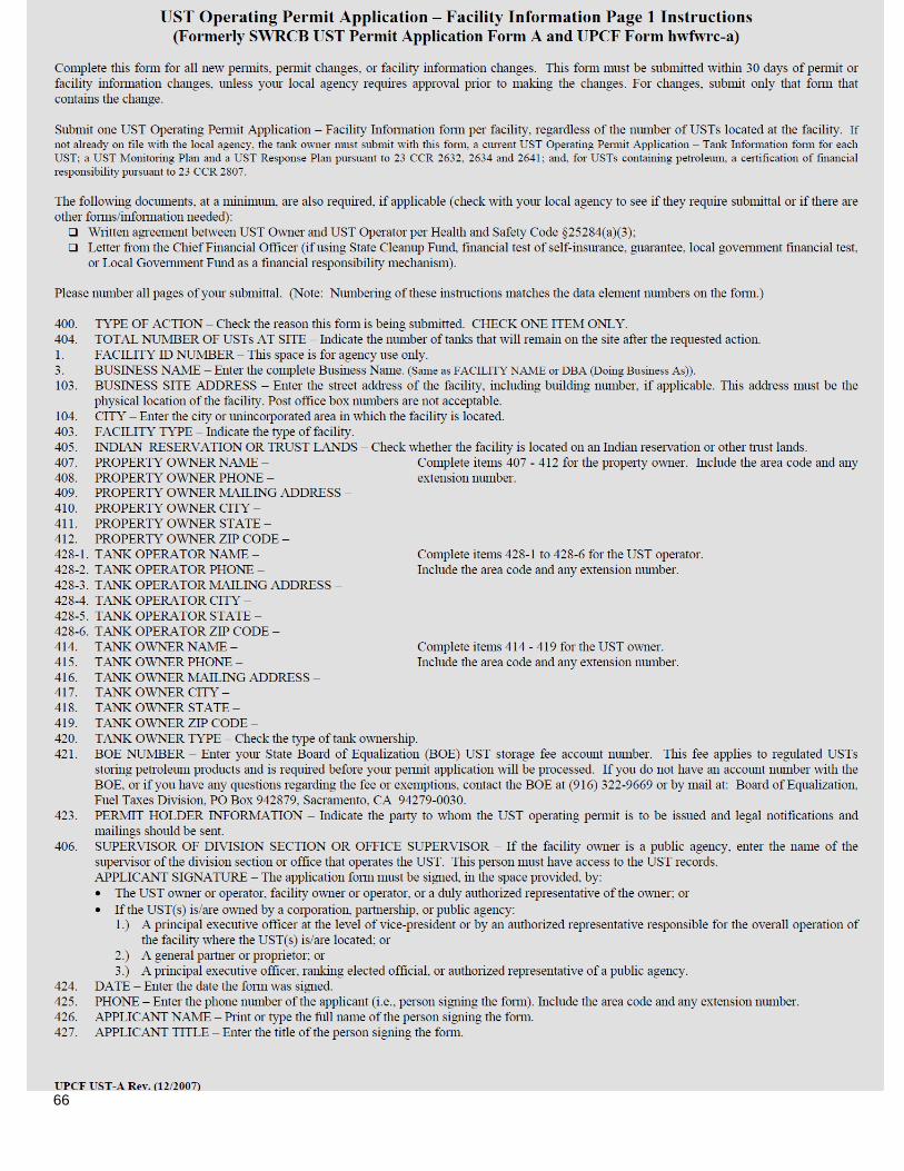
66

67

68

69

70

71
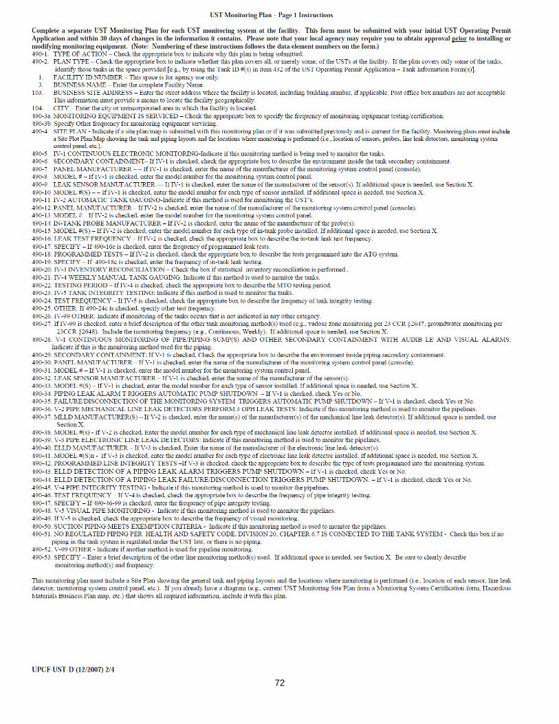
72

73

74

75
UNDERGROUND STORAGE TANK
RESPONSE PLAN – PAGE 1 (One form per facility)
TYPE OF ACTION 1. NEW PLAN 2. CHANGE OF INFORMATION R01.
I. FACILITY INFORMATION FACILITY ID # (Agency Use Only) — —
1.
BUSINESS NAME (Same as FACILITY NAME) 3.
BUSINESS SITE ADDRESS 103. BUSINESS SITE CITY 104.
II. SPILL CONTROL AND CLEANUP METHODS This plan addresses unauthorized releases from UST systems and supplements the emergency response plans and procedures in the facility's Hazardous Materials
Business Plan (HMBP).
If safe to do so, facility personnel will take immediate measures to control or stop any release (e.g., activate pump shut-off, etc.) and, if necessary, safely remove remaining hazardous material from the UST system.
Any release to secondary containment will be pumped or otherwise removed within a time consistent with the ability of the secondary containment system to
contain the hazardous material, but not greater than 30 calendar days, or sooner if required by the local agency. Recovered hazardous materials, unless still suitable for their intended use, will be managed as hazardous waste.
Absorbent material will be used to contain and clean up manageable spills of hazardous materials. Absorbent material which has become too saturated to be
effective or which is no longer intended for use will be managed as hazardous waste unless a waste determination in accordance with 22 CCR §66262.11 finds that it is non-hazardous. Used absorbent material, reusable or waste, will be stored in a properly labeled and sealed container. Waste material shall be disposed of
appropriately.
Facility personnel will determine whether any water removed from secondary containment systems, or from clean-up activity, has been in contact with any hazardous material. If the water is contaminated, it will be managed as hazardous waste unless a hazardous waste determination in accordance with 22 CCR
§66262.11 finds that it is non-hazardous. If the water has a petroleum sheen (i.e., rainbow colors), it is contaminated. A thick floating petroleum layer may not
necessarily display rainbow colors. Water (hazardous or non-hazardous) from sumps, spill containers, etc. will not be disposed to storm water systems. We will review secondary containment systems for possible deterioration if any of the following conditions occur:
1. Hazardous material in contact with secondary containment is not compatible with the material used for secondary containment;
2. Secondary containment is prone to damage from any equipment used to remove or clean up hazardous material collected in secondary containment; 3. Hazardous material, other than the product/waste stored in the primary containment system, is placed inside secondary containment to treat or neutralize
released product/waste, and the added material or resulting material from such a combination is not compatible with secondary containment.
III. SPILL CONTROL AND CLEAN-UP EQUIPMENT PERIODIC MAINTENANCE: Spill control and clean-up equipment kept permanently on-site is listed in the facility’s Hazardous Materials Business Plan. This
equipment is inspected at least monthly, and after each use, supplies are replenished as needed. Defective equipment is repaired or replaced as necessary.
EQUIPMENT NOT PERMANENTLY ON-SITE, BUT AVAILABLE FOR USE IF NEEDED: (Complete only if applicable) EQUIPMENT LOCATION AVAILABILITY
R10.
R20.
R30.
R11.
R21.
R31.
R12.
R22.
R32.
R13.
R23.
R33.
R14.
R24.
R34.
R15.
R25.
R35.
IV. RESPONSIBLE PERSONS
THE FOLLOWING PERSON(S) IS/ARE RESPONSIBLE FOR AUTHORIZING ANY WORK NECESSARY UNDER THIS RESPONSE PLAN:
NAME
R40. TITLE
R50.
NAME
R41. TITLE
R51.
NAME
R42. TITLE
R52.
NAME
R43. TITLE
R53.
V. MONITORING INDICATORS IF MONITORING INDICATES A POSSIBLE UNAUTHORIZED RELEASE, STEPS TO VERIFY THE RELEASE WILL BE MADE AS FOLLOWS:
1. ADDITIONAL SYSTEM TESTING OR DATA COLLECTION 2. INSPECTION BY QUALIFIED PERSONS 3. RECALIBRATION OF EQUIPMENT R60.
99. OTHER (Specify): R61.

76
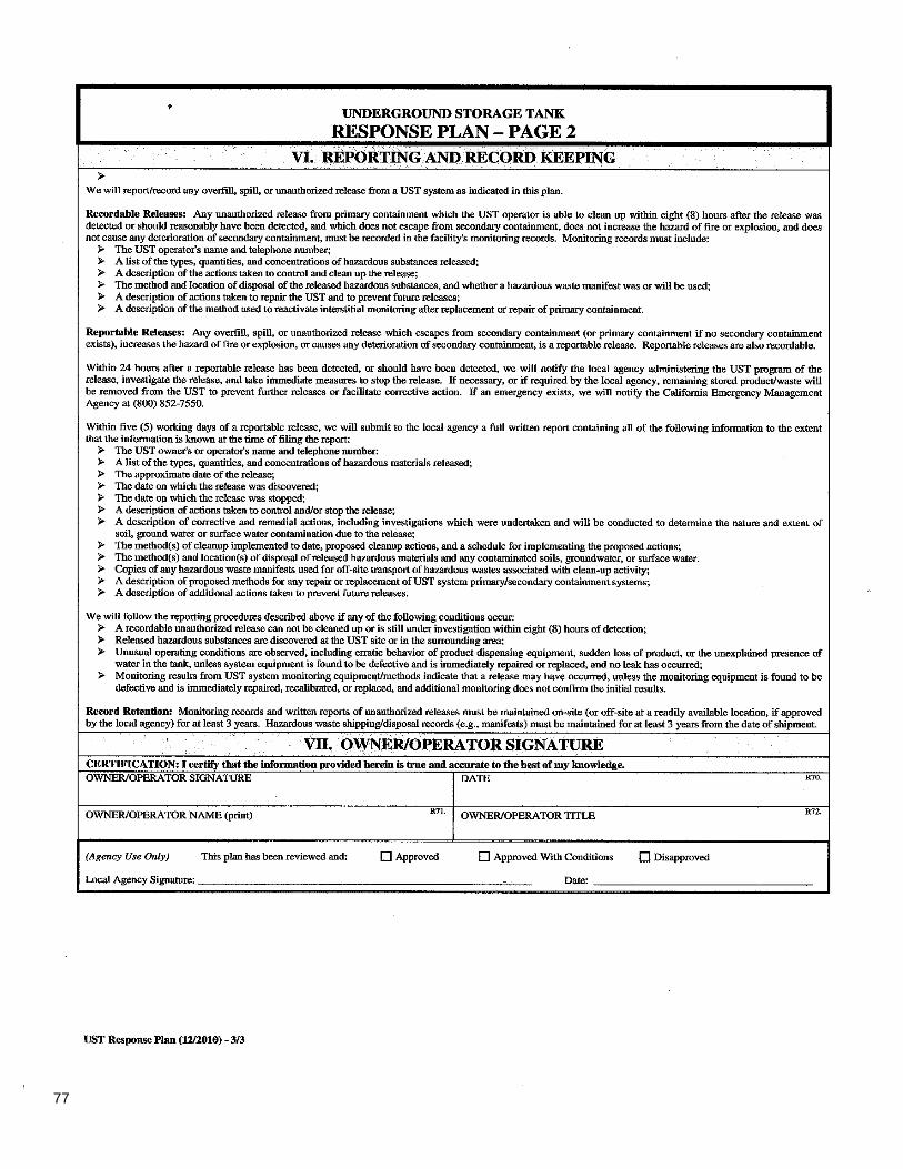
77