for rotax 912 s aircraft engine - kitfox airplanes in eu · this installation manual is to acquaint...
TRANSCRIPT

Recommended price: ATS 200,-- part no. 899 376
Installation Manualfor
ROTAX 912 SAircraft Engine
WARNINGBefore starting with the engine installation, please,
read the Installation Manual completely as it contains important safety-relevant information.
The Manual must remain with the engine / aircraft in case of sale.
Edition: 0 of 1998 09 01
These technical data and the information contained therein are property of ROTAX® GmbH
and must not be reproduced, neither in entirety nor partially, and passed on to third partieswithout previous consent in writing by BOMBARDIER-ROTAX GmbH. This text must bewritten on every complete or partial reproduction.
Copyright - ROTAX ® GmbH
Approval of translation to best knowledge and judgement - in any case the original text in German language is authoritative.
AIRCRAFT ENGINES

Preference Modification no.- 0 -
Date1998
Install912 S
0) PrefaceCongratulation on your decision to use a ROTAX® aircraft engine.
Before starting with the engine installation, read this Installation Manual carefully. TheManual will provide you with basic information on correct engine installation, a requirementfor safe engine operation.
If any passages of the Manual are not completely understood or in case of questions, please,contact an authorized Distribution- or Service Partner for ROTAX® engines.
We wish you much pleasure and satisfaction flying your aircraft powered by this ROTAX ®
engine.
0.1) RemarksThis Installation Manual is to acquaint the owner/user of this aircraft engine with basicinstallation instructions and safety information.
For more detailed information on operation, maintenance, safety- or flight, consult thedocumentation provided by the aircraft builder and dealer.
For further information on maintenance and spare part service contact the nearestROTAX® distributor (see chapter of Service Partners).
0.2) Engine serial numberOn all enquiries or spare parts orders, always indicate the engine serial number, asthe manufacturer makes modifications to the engine for further development.
The engine serial number is on the top of the crankcase, magneto side.

PreferenceModification no.- 0 -
Page1 - 1
Date1998 09 01
Install912 Sd0
0168
1) SafetyAlthough the mere reading of these instructions will not eliminate a hazard, the understandingand application of the information herein will promote the proper installation and use of theengine.
The information and components-/system descriptions contained in this Installation Manualare correct at the time of publication. ROTAX®, however, maintains a policy of continuousimprovement of its products without imposing upon itself any obligation to install them on itsproducts previously manufactured.
ROTAX® reserves the right at any time to discontinue or change specifications, designs,features, models or equipment without incurring obligation.
The fig.s in this Installation Manual show the typical construction. They may not represent infull detail or the exact shape of the parts which have the same or similar function.
Specifications are given in the SI (-metric) system with the USA equivalent in parenthesis.Where precise accuracy is not required, some conversions are rounded off for easier use.
1.1) Repeating symbolsThis Manual uses the following symbols to emphasize particular information. Theseindications are important and must be respected.
WARNING: Identifies an instruction which, if not followed, may cause seriousinjury including the possibility of death.
ATTENTION: Denotes an instruction which, if not followed, may severely damagethe engine or other component.
NOTE: Indicates supplementary information which may be needed to fullycomplete or understand an instruction.

Preference Modification no.- 0 -
Page1 - 2
Date1998 09 01
Install912 S d0
0168
1.2) Safety information WARNING: Only certified technicians (authorized by the local airworthiness
authorities) and trained on this product are qualified to work on theseengines.
WARNING: Never fly the aircraft equipped with this engine at locations, airspeeds,altitudes, of other circumstances from which a successful no-powerlanding cannot be made, after sudden engine stoppage.Aircraft equipped with this engine must only fly in DAYLIGHT VFRconditions.
This engine is designed for possible application on aircraft used in VFR condi-tions which have the capability of controlled gliding without engine power.
This engine is not suitable for acrobatics (inverted flight, etc.).
This engine shall not be used on rotor wing aircraft (helicopters, gyrocopters, etc.)or any similar aircraft.
It should be clearly understood that the choice, selection and use of this particularengine on any aircraft is at the sole discretion and responsibility of the aircraftmanufacturer, assembler and owner/user.
Due to the varying designs, equipment and types of aircraft, ROTAX® makes nowarranty or representation on the suitability of its engine’s use on any particularaircraft. Further, ROTAX® makes no warranty or representation of this engine’ssuitability with any other part, component or system which may be selected by theaircraft manufacturer, assembler or user for aircraft application.
Whether you are a qualified pilot or a novice, complete knowledge of the aircraft, itscontrols and operation is mandatory before venturing solo. Flying any type of aircraftinvolves a certain amount of risk. Be informed and prepared for any situation orhazard associated with flying. A recognized training program and continued educa-tion for piloting an aircraft is absolutely necessary for all aircraft pilots. Make sure youalso obtain as much information as possible about your aircraft, its maintenance andoperation from your dealer.
You should be aware that any engine may seize or stall at any time. This could leadto a crash landing and possible severe injury or death. For this reason, werecommend strict compliance with the maintenance and operation and any addi-tional information which may be given to you by your dealer.
Respect all government or local rules pertaining to flight operation in your flying area.Fly only when and where conditions, topography, and airspeeds are safest.
Select and use proper aircraft instrumentation. This instrumentation is not includedwith the ROTAX
® engine package. Only approved instrumentation can be installed.
Before flight, ensure all engine controls are operative. Make sure all controls can beeasily reached in case of an emergency.
Unless in a run up area, never run the engine with the propeller turning while on theground. Do not operate engine if bystanders are close.
To prevent unauthorized use, never leave the aircraft unattended with the enginerunning.

PreferenceModification no.- 0 -
Page1 - 3
Date1998 09 01
Install912 Sd0
0168
Keep an engine log and respect engine and aircraft maintenance schedules. Keepthe engine in top operating condition at all times. Do not operate any aircraft whichis not properly maintained or has engine operating irregularities which have not beencorrected. Since special tools and equipment may be required, engine servicingshould only be performed by an authorized ROTAX® engine dealer or a qualifiedtrained mechanic approved by the local airworthiness authority.
To eliminate possible injury or damage, ensure that any loose equipment or tools areproperly secured before starting the engine.
When in storage protect the engine and fuel system from contamination andexposure.
Certain areas, altitudes and conditions present greater risk than others. The enginemay require carburetor recalibration or humidity or dust/sand preventative equip-ment, or additional maintenance may be required. Consult your aircraft dealer ormanufacturer and obtain the necessary information, especially before flying in newareas.
Never operate the engine and gearbox without sufficient quantities of lubricating oil.
Periodically verify level of coolant.
Never exceed maximum rated rpm. and allow the engine to cool at idle for severalminutes before turning off the engine.
Operating the engine at high speed at low throttle position, for example duringdescent, may increase engine and exhaust temperatures and cause critical over-heating. Always compensate and match rpm. with throttle position.
The engine should only be installed and placed into operation by persons familiarwith the use of the engine and informed with regard to possible hazards.
Never run the engine without a propeller as this will inevitably cause engine damageand present a hazard of explosion.
Propeller and its attachment with a moment of inertia in excess of the specified valuemust not be used and releases engine manufacturer from any liability.
Improper engine installation and use of unsuitable piping for fuel,- cooling,- andlubrication system releases engine manufacturer from any liability.
Unauthorized modifications of engine or aircraft will automatically exclude anyliability of the manufacturer for sequential damage.
In addition to observing the instructions in our Manual, general safety and accidentpreventative measures, legal regulations and regulations of any aeronauticalauthority must be observed.
Where differences exist between this Manual and regulations provided by anyauthority, the more stringent regulation should be applied.
This engine may be equipped with an Airborne air pump. The safety warningaccompanying the air pump must be given to the owner/operator of the aircraft intowhich the air pump is installed.

Preference Modification no.- 0 -
Page1 - 4
Date1998 09 01
Install912 S d0
0168
1.3) InstructionEngines require instructions regarding their application, use, operation, maintenanceand repair.
Technical documentation and directions are useful and necessary complementaryelements for personal instruction, but can by no means substitute theoretical andpractical instructions.
These instructions should cover explanation of the technical context, advice foroperation, maintenance, use and operational safety of the engine.
All technical directives relevant for safety are especially emphasized. Pass onsafety instructions to other users, without fail.
This engine must only be operated with accessories supplied, recommended andreleased by ROTAX. Modifications are only allowed after consent by the enginemanufacturer.
ATTENTION: Spare parts must meet with the requirements defined by the enginemanufacturer. This is only warranted by use of GENUINE ROTAXspare parts and/or accessories (see spare parts list).
They are available only at the authorized ROTAX® Distribution- andService partners.
The use of anything other than genuine ROTAX® spare parts and/or
accessories will render any warranty relating to this engine null and void(see Warranty Conditions).
WARNING: Engine and gear box are delivered in "dry" conditions (without oil).Before putting engine in operation it must be filled with oil. Use onlyoil as specified (consult Operator‘s Manual).
For longer periods (longer than 2 months) of engine stop, preservation of engineis recommended (see chapter engine preservation in Operator‘s Manual).
WARNING: Exclusively use tools and supplementary materials as listed in thespare parts list.
WARNING: This Manual for engine installation is only part of the TechnicalDocumentation and will be supplemented by the respective Opera-tor‘s Manual, Maintenance Manual and Spare Parts List.
Pay attention to references to other documentation, found in variousparts of this Manual.

PreferenceModification no.- 0 -
Page1 - 5
Date1998 09 01
Install912 Sd0
0168
1.4) Technical documentationThe information given in the
Installation Manual
Operator‘s Manual
Maintenance Manual
Overhaul Manual
Spare parts list
Technical bulletins
Service Informations
are based on data and experience that are considered applicable for professionalsunder normal conditions.
The fast technical progress and variations of installation might render present lawsand regulations inapplicable or inadequate.
NOTE: The illustrations in this Maintenance Manual are stored in a graphicdata file and are provided with a consecutive irrelevant number.
This number (e.g. 00288 ) is of no significance for the content.

Preference Modification no.- 0 -
Page1 - 6
Date1998 09 01
Install912 S d0
0168
Blank page
PreferenceModification no.- 0 -
Page2 - 1
Date1998 09 01
Install912 Sd0
0169
2) Table of contents0) Preface .............................................................................................................. 0 - 2
0.1) Remarks ............................................................................................................... 0 - 20.2) Engine serial number........................................................................................... 0 - 2
1) Safety ................................................................................................................ 1 - 11.1) Repeating symbols .............................................................................................. 1 - 11.2) Safety information ................................................................................................ 1 - 21.3) Instruction ............................................................................................................ 1 - 41.4) Technical documentation ..................................................................................... 1 - 5
3) Index .................................................................................................................. 3 - 1
4) List of the current pages ................................................................................. 4 - 1
5) Table of amendments ...................................................................................... 5 - 1
6) Description of design ...................................................................................... 6 - 16.1) Designation of type .............................................................................................. 6 - 16.2) Standard engine design ...................................................................................... 6 - 16.3) Engine components and views, numbering of cyl., definition of main axes ....... 6 - 3
7) Technical data .................................................................................................. 7 - 17.1) Operating limits .................................................................................................... 7 - 17.2) Installation dimensions (all dimensions in mm) ................................................... 7 - 27.3) Weights ................................................................................................................ 7 - 27.4) Centre of gravity of engine and standard equipment.......................................... 7 - 27.5) Moments of inertia in kg cm2 .............................................................................. 7 - 2
8) Preparations for engine installation ............................................................... 8 - 18.1) Transport .............................................................................................................. 8 - 18.2) State of delivery ................................................................................................... 8 - 18.3) Engine preservation............................................................................................. 8 - 18.4) Protective covering .............................................................................................. 8 - 2
9) Engine suspension and position ................................................................... 9 - 19.1) Definition of attachment points ............................................................................ 9 - 19.2) Permissible fitting positions ................................................................................. 9 - 29.3) General directives for engine suspension ........................................................... 9 - 3
10) Exhaust system .............................................................................................. 10 - 110.1) Requirements on the exhaust system ............................................................... 10 - 110.2) General directives for exhaust-system .............................................................. 10 - 2
11) Cooling system .............................................................................................. 11 - 111.1) Requirements on the cooling system ................................................................ 11 - 111.2) Size and position of connections....................................................................... 11 - 111.3) Coolant capacity ................................................................................................ 11 - 211.4) Feasible location of radiator .............................................................................. 11 - 311.5) General directives for the cooling system ......................................................... 11 - 4
12) Cooling air ducting ........................................................................................ 12 - 112.1) General directives for ducting of the cooling air ................................................ 12 - 1
12.1.1) Cylinder wall temperature ............................................................................... 12 - 2

Preference Modification no.- 0 -
Page2 - 2
Date1998 09 01
Install912 S d0
0169
13) Lubrication system (oil system) ................................................................... 13 - 113.1) Requirements on the lubrication system ........................................................... 13 - 113.2) Size and position of connections....................................................................... 13 - 213.3) Feasible position and location of the oil tank .................................................... 13 - 413.4) Feasible position and location of the oil cooler ................................................. 13 - 513.5) Filling capacity ................................................................................................... 13 - 513.6) Venting of the lubrication system ...................................................................... 13 - 5
14) Fuel system .................................................................................................... 14 - 114.1) Requirements on the fuel system ...................................................................... 14 - 214.2) Definition and size of connection ...................................................................... 14 - 3
15) Carburetor ....................................................................................................... 15 - 115.1) Requirements on the carburetor........................................................................ 15 - 115.2) Dimensions for installation and limit load .......................................................... 15 - 115.3) General directives .............................................................................................. 15 - 2
16) Air intake system ........................................................................................... 16 - 116.1) Requirement on the intake system.................................................................... 16 - 1
17) Electric system ............................................................................................... 17 - 117.1) Technical data and connection of the electric components .............................. 17 - 2
18) Propeller drive ................................................................................................ 18 - 118.1) Technical data: ................................................................................................... 18 - 1
19) Vacuum pump................................................................................................. 19 - 119.1) Technical data: .................................................................................................. 19 - 1
20) Hydraulic governor for constant speed propeller ....................................... 20 - 120.1) Technical data: ................................................................................................... 20 - 1
21) Connections for instrumentation ................................................................. 21 - 121.1) Sensor for cylinder head temperature: .............................................................. 21 - 121.2) Sensor for oil temperature: ................................................................................ 21 - 221.3) Oil pressure pick-up: .......................................................................................... 21 - 321.4) Mechanical rev-counter or hour-meter: ............................................................. 21 - 420.5) Monitoring of the intake manifold pressure ....................................................... 21 - 4
22) Preparations for trial run of engine .............................................................. 22 - 1
23) ROTAX Authorized Distributors for Aircraft Engines .................................. 23 - 1

PreferenceModification no.- 0 -
Page3 - 1
Date1998 09 01
Install912 Sd0
0170
3) IndexAAmbient temperature 7 - 1attachment points 9 - 1Auxiliary equipment 6 - 2Auxiliary generator 17 - 5
Bback pressure 10 - 1Battery 17 - 7
CCarburetor 15 - 1Carburetor flange 15 - 1Carburetor venting lines 15 - 1Centre of gravity 7 - 2choke 15 - 2Coarse filter 14 - 2Colour code 17 - 1constant speed propeller 20 - 1continuous speed 7 - 1Coolant capacity 11 - 2Coolant hoses 11 - 1cooling air 12 - 1Cooling air ducting 12 - 1Cooling system 11 - 1coordinates 6 - 3cyl. head temperature 7 - 1, 21 -1Cylinder wall temperature 12 - 2
DDelivery rate 14 - 2denomination of cylinders 6 - 3Description of design 6 - 1Designation of type 6 - 1Distributors 23 - 1Drain holes 16 - 2
EEGT 7 - 1, 10 - 1electric rev-counter 17 - 6electric rev-counter connection17 - 6electric system 17 - 1electric-starter 17 - 3EMC 17 - 7EMI 17 - 7Engine components 6 - 3engine design 6 - 1engine installation 8 - 1Engine position 9 - 1Engine preservation 8 - 1Engine serial number 0 - 2engine suspension 9 - 1, 9 - 3engine trial run 22 - 1engine views 6 - 3exhaust bend 10 - 1exhaust gas temperature 7 -1, 10 - 1exhaust socket 10 - 1exhaust system 10 - 1expansion tank 11 - 1
FFine filter 14 - 1, 14 - 2Fuel filter 14 - 2Fuel lines 14 - 2Fuel manifold 14 - 3Fuel pressure 7 - 1, 14 - 2Fuel system 14 - 1Fuel temperature 14 - 2
Ggovernor 20 - 1
Hhour-meter 21 - 4Hydraulic governor for constantspeed propeller 20 - 1
Iidle speed 7 - 1Ignition switch 17 - 3Index 3 - 1Installation dimensions 7 - 2Instruction 1 - 4instrumentation 21 - 1Instrumentation connection 21 -1Intake manifold pressure 21 - 4Integrated generator 17 - 2
LList of the current pages 4 - 1
Mmain axes 6 - 3Manifold pressure 16 - 2manifold pressure 21 - 4Mechanical rev-counter 21 - 4Moments of inertia 7 - 2muffler volume 10 - 1
Nnegative gravity 7 - 1negative gravity acceleration 7 -1numbering of cylinders 6 - 3
OOil pressure 7 - 1Oil pressure pick-up 21 - 3Oil temperature 7 - 1oil temperature sensor 21 - 2On-Off switch 17 - 3Operating limits 7 - 1operating temperature 7 - 1Optional extras 6 - 1Overflow bottle 11 - 3overflow bottle 11 - 3
PPermissible fitting positions 9 - 2Preface 0 - 2Preparations for engine installa-tion 8 - 1preservation (engine) 8 - 1
Propeller drive 18 - 1Protective covering 8 - 2protective covering 8 - 2
Rradiator location 11 - 3Range of operating temperature7 - 1Rectifier-regulator 17 - 2Remarks 0 - 2Repeating symbols 1 - 1Rev-counter drive 21 - 4
SSafety 1 - 1Safety information 1 - 2Sensor for oil temperature 21 -2Shorting switch 17 - 3Standard engine design 6 - 1Start relais 17 - 4Start relay 17 - 4State of delivery 8 - 1
TTable of amendments 5 - 1Table of contents 2 - 1Take-off speed 7 - 1Takeoff speed 7 - 1Technical data 7 - 1Technical documentation 1 - 5Transport 8 - 1Trial run 22 - 1
VVacuum pump 19 - 1
WWater inlet bend 11 - 2Weights 7 - 2

Preference Modification no.- 0 -
Page3 - 2
Date1998 09 01
Install912 S d0
0170
Blank page

PreferenceModification no.- 0 -
Page4 - 1
Date1998 09 01
Install912 Sd0
0171
chapter page date0 0 - 2 98 07 01
1 1 - 1 98 07 01
1 - 2 98 07 01
1 - 3 98 07 01
1 - 4 98 07 01
1 - 5 98 07 01
1 - 6 98 07 01
2 2 - 1 98 07 01
2 - 2 98 07 01
3 3 - 1 98 07 01
3 - 2 98 07 01
4 4 - 1 98 07 01
4 - 2 98 07 01
5 5 - 1 98 07 01
5 - 2 98 07 01
6 6 - 1 98 07 01
6 - 2 98 07 01
6 - 3 98 07 01
6 - 4 98 07 01
7 7 - 1 98 07 01
7 - 2 98 07 01
8 8 - 1 98 07 01
8 - 2 98 07 01
9 9 - 1 98 07 01
9 - 2 98 07 01
9 - 3 98 07 01
9 - 4 98 07 01
10 10 - 1 98 07 01
10 - 2 98 07 01
11 11 - 1 98 07 01
11 - 2 98 07 01
11 - 3 98 07 01
11 - 4 98 07 01
12 12 - 1 98 07 01
12 - 2 98 07 01
13 13 - 1 98 07 01
13 - 2 98 07 01
13 - 3 98 07 01
13 - 4 98 07 01
13 - 5 98 07 01
13 - 6 98 07 01
14 14 - 1 98 07 01
14 - 2 98 07 01
14 - 3 98 07 01
14 - 4 98 07 01
15 15 - 1 98 07 01
15 - 2 98 07 01
16 16 - 1 98 07 01
16 - 2 98 07 01
4) List of the current pages02014 02036
chapter page date17 17 - 1 98 07 01
17 - 2 98 07 01
17 - 3 98 07 01
17 - 4 98 07 01
17 - 5 98 07 01
17 - 6 98 07 01
17 - 7 98 07 01
17 - 8 98 07 01
18 18 - 1 98 07 01
18 - 2 98 07 01
19 19 - 1 98 07 01
19 - 2 98 07 01
20 20 - 1 98 07 01
20 - 2 98 07 01
21 21 - 1 98 07 01
21 - 2 98 07 01
21 - 3 98 07 01
21 - 4 98 07 01
22 22 - 1 98 07 01
22 - 2 98 07 01
23 23 - 1 98 07 01
23 - 2 98 07 01
23 - 3 98 07 01
23 - 4 98 07 01

Preference Modification no.- 0 -
Page4 - 2
Date1998 09 01
Install912 S d0
0171
Blank page

PreferenceModification no.- 0 -
Page5 - 1
Date1998 09 01
Install912 Sd0
0172
5) Table of amendments 00159
0 0-23 all 1998 07 01 not required 1998 10 01 AA/HEC
lfd. Ab- Datum der Anerkennungs- Datum Anerk. der Datum der Zeichen/Nr. schnitt Seiten Berichtigung Vermerk genehm. Behörde Einarbeitung Unterschrift

Preference Modification no.- 0 -
Page5 - 2
Date1998 09 01
Install912 S d0
0172
Blank page

PreferenceModification no.- 0 -
Page6 - 1
Date1998 09 01
Install912 Sd0
0173
6) Description of design
6.1) Designation of typeBasic type:
e.g. ROTAX 912 S 2
S2: with prop flange for fix pitch propeller
S3: with prop flange with drive of hydraulic governor for constant speed propeller
S4: with prop flange for fix pitch propeller, but prepared for retrofit of hydraulicgovernor for constant speed prop
Optional extras to the above stated basic type:
NOTE: Conversion of the types S2, S4 to type S3 may be accomplished bythe manufacturer (ROTAX®).
6.2) Standard engine design 4 stroke, 4 cyl. horizontally opposed, spark ignition engine, single central camshaft
hydraulic tappets - push rods - OHV
liquid cooled cylinder heads
ram air cooled cylinders
dry sump, forced lubrication
ROTAX dual ignition, breakerless, capacitor discharge, interference suppression
2 constant depression carburetors
mechanical fuel pump
oil tank
expansion tank (coolant)
propeller drive via integrated gear box with torsional shock absorber and overloadclutch
electric starter
external start relay
integrated AC generator
external rectifier-regulator
hydraulic governor for constant speed prop (for S3 only)
intake silencer
02016
auxiliary alternator
vacuum- pump
drive for revcounter / hour meter
for S2 yes yes yes
for S3 yes no yes
for S4 yes yes yes

Preference Modification no.- 0 -
Page6 - 2
Date1998 09 01
Install912 S d0
0173
auxiliary generator (optional extra)
vacuum pump (optional extra)
drive for rev-counter / hour-meter (optional extra)
engine suspension frame (optional extra)
Auxiliary equipment
ATTENTION: Any equipment not included as part of the standard engine versionand thus not a fix component of the engine is not in the scope ofsupply.
Components especially developed and tested for this engine arereadily available at ROTAX®.
WARNING: This equipment has not been tested for safety and durabilityto the standards of aviation. The user assumes all risks possiblyarising by utilizing auxiliary equipment.
The furnishing of proof in accordance to the latest FAR or JAR hasto be conducted by the aircraft or fuselage manufacturer.
Exhaust system
Intake filter
Oil cooler
Coolant radiator
Flydat
Mechanical rev counter
Electric rev counter
Hour-meter

PreferenceModification no.- 0 -
Page6 - 3
Date1998 09 01
Install912 Sd0
0173
6.3) Engine components, engine views, numbering of cylinders, definition ofmain axesSee fig. 2, 3 and 4.
PTO power take off side
MS magneto side
A points of attachment for engine transport
centre of gravity
P zero reference point for all dimensions
x,y,z axes for system of coordinates
Cyl. 1 cylinder 1
Cyl. 2 cylinder 2
Q propeller flange
W propeller gear
E vacuum pump or hydraulic gover-nor for constant speed propeller
R intake manifold
T constant depr. carburetor cyl. 1/3
Y constant depr. carburetor cyl. 2/4
U connection for mechanical rev-counter
I coolant pump
O connection for oil return line
P mechanical fuel pump
exhaust socket
electric starter
Cyl. 3 cylinder 3
Cyl. 4 cylinder 4
q expansion tank
w oil filter
e oil pump
r fly wheel fixation screw
t pressure compensating tube
y sensor for oil pressure
u sensor for oil temperature
i sensor for cylinder head temperature
o electronic modules of ignition unit
p connection for intake manifold pressure
[ ignition housing
] external alternator
+z
-z
+x -xP
AS MS
A
+z1
-x1+x1
-z1
Bild 2
2
9
1
3
7
820
00502

Preference Modification no.- 0 -
Page6 - 4
Date1998 09 01
Install912 S d0
0173
P
+z1
+y1-y1
-z1
+z
-z
-y +y
Bild 3
Bild 4
5 6
19
12
16
4
4
10
11
cyl. 2
cyl. 3
cyl. 1
cyl. 4
18
15
11
14
17
21
1322
23
24
00503
00504
AA
-x
+x
-y +y
P
-x1+y1-y1
+x120
20

PreferenceModification no.- 0 -
Page7 - 1
Date1998 09 01
Install912 Sd0
0174
7) Technical dataTo maintain clarify, only data relevant for engine installation and operation will be stated inthe Manual.
NOTE: Connecting dimensions, filling capacities, drive and reduction ratios,electric output etc. can be found in the respective chapter of engineinstallation.
7.1) Operating limits1. Takeoff speed: ................................................... 5800 rpm. (5 min.)
max. continuous speed: ..................................... 5500 rpm.idle speed: ......................................................... around 1400 rpm.
2. Time limit for engine operation at weightless condition and with negative gravityacceleration: ...................................................... max. 5 sec at max. -0,5 g
3. Oil pressure: see fig. 46max. 7 bar (100 psi) ........................................... (at cold start a pressure of up to 7
bar =100 psi, is permitted for ashort period).
min. .................................................................... 0,8 bar (12 psi) (below 3500 RPM)
normal ................................................................ 2,0 - 5,0 bar (29-73 psi)(over 3500RPM)
4. Oil temperature (see fig. 45) readingin feed line to engine: ......................................... min. 50° C (120° F)
max. 130° C (266° F)normal operating temperature: .......................... 90 ÷ 110° C (190 ÷ 250° F)
5. Max. cylinder head temperature, reading on the pre installed sensorspot of the hottest cylinder: ................................ 135° C (275° F)
NOTE: Investigation should be conducted to identify the hottest cylinder (cyl.2 or 3), depending on the installation (tractor or pusher arrangement).See fig. 2 and 4.
6. Exhaust gas temperature (EGT): ....................... max. 880° C (1620° F) at take offmax. 850° C (1560° F)normal operat. 800°C (1470° F)
(reading c. 70 mm = 2,75in. after exhaust flange)
7. Range of operating temperature: ...................... +50 (120°F) to -25° C (-13° F)
fig. 5
00506
40°
00505
8. Ambient temperature for electric components: (fig.4, pos. i)max. 80° C (176° F)
9. Fuel pressure: .......................... 0,15 ÷ 0,4 bar (2,2 ÷ 5,8 psi.)(see fig. 22 and 23) .................. max. 0,4 bar (5,8 psi.)10.Banking of
plane: (if not statedotherwise) deviation
from the effective vertical ........ max. 40°
Up to this inclination the dry sump lubrication system warrantsadequate lubrication in every flight situation.

Preference Modification no.- 0 -
Page7 - 2
Date1998 09 01
Install912 S d0
0174
7.2) Installation dimensions (all dimensions in mm)See fig. 2, 3 and 4.
NOTE: Dimensions to point of reference (P). See fig. 2, 3 and 4.
7.3) WeightsWeight of engine defined to the following conditions:
Engine dry from serial production (see chapter description of design)
Engine weight Version S2 and S4: ........................ 58,3 kg (128 lb.)Version S3: ..................................... 61 kg (134 lb.)
Weight of external generator assy.: .................. 3,0 kg (6,6 lb.)vacuum pump assy.: ........................ 0,8 kg (1,76 lb.)hydraulic governor assy.: ................. 2,7 kg (6 lb.)engine suspension frame: ................ 2,0 kg (4 lb.)
7.4) Centre of gravity of engine and standard equipmentSee fig. 2, 3 and 4.
NOTE: Dimensions to point of reference (P). See fig. 2, 3 and 4.
7.5) Moments of inertia in kg cm2See fig. 2, 3 and 4.
02017
02018
02019
standard engine version
pos. (+) neg. (-) total
max. dimension in x axis 8,5 -581 589,5
max. dimension in y axis 288 -288 576,0
max. dimension in z axis 118 -276 394,0
engine from serial
production S2
auxiliary alternator
hydraulic governor
vacuum- pump
centre of gravity in x-axis -316 -100 -276 -255
centre of gravity in y-axis -5 139 0 0
centre of gravity in z-axis -83 6 56 56
version S2 / S4
version S3
moment of inertia around axis x1 - x1 (kg cm2)
11 100 11 600
moment of inertia around axis y1 - y1 (kg cm2)
10 900 11 390
moment of inertia around axis z1 - z1 (kg cm2)
17 400 18 200

PreferenceModification no.- 0 -
Page8 - 1
Date1998 09 01
Install912 Sd0
0175
8) Preparations for engine installation ATTENTION: The stated directives are measures to pay attention to at engine
installation to prevent any accidents and engine damage.
8.1) TransportThe engine to be lifted by two hooks or straps around the middle of the intakemanifolds.
See chapter engine views, numbering of cylinders and definition of main axes.
8.2) State of deliveryThe engine is attached with 4 Allen screws M10x20 to steel angles anchored on atimber plate.
8.3) Engine preservationThe engine is preserved at ROTAX thus warranting proper protection againstcorrosion for at least 12 month after date of delivery from ROTAX®.
This warranty is subject to the following conditions:
the engine has to be stored in the packing as supplied by ROTAX.
the covers on various openings must not be removed (see chapter of protectivecovering)
engine has to be stored in a suitable place.
If the engine is stored for a period longer than 12 month the following tasks have tobe performed every three months:
crank the engine by hand on attachment screw of flywheel two complete turnsanticlockwise (viewed from Magneto side). See fig. 4.
inspect for corrosion (e.g. prop shaft). At detection of corrosion, send the engineto the overhauler without delay.
WARNING: The engine must not be put into service.
repack engine into original packaging and seal properly.
WARNING: The maximum storage period is limited to 24 month!
Preservation for periods of longer than 24 months is only possibleafter a written permission of ROTAX
®. Should the situation arise
send engine for inspection to ROTAX.
NOTE: No trouble to put engine back into operation after preservation.

Preference Modification no.- 0 -
Page8 - 2
Date1998 09 01
Install912 S d0
0175
8.4) Protective coveringAll openings are protected against ingress of contamination and dampness. It isrecommended not to remove these plugs until installation of the specific feed line.
NOTE: If the engine will be sent to the manufacturer or distributor reusetransport equipment and replug openings.
List of protective covering:
exhaust sockets: ................................................ 1 each cone plug
carburetor inlet: .................................................. 1 each cover
intake silencer: ................................................... 2 caps
fuel pump inlet: .................................................. 1 cap
connection for fuel return: .................................. 1 plug
connection for fuel pressure: ............................. 1 plug
oil supply and oil return: ..................................... 1 each cap
supply and return of coolant: ............................. 1 each cone plug
prop shaft on version S3 and S4: ...................... 1 disc plug
WARNING: Protective covering to be utilized for transport and at engineinstallation only. For engine operation remove these protections.

PreferenceModification no.- 0 -
Page9 - 1
Date1998 09 01
Install912 Sd0
0176
9) Engine suspension and position ATTENTION: At installation of engine be aware of engine weight and assure careful
handling.
The engine suspension is determined essentially by the aircraft design. Eight attachmentpoints are provided on the engine.
WARNING: At least four of the eight anchorage points must be used in a side-symmetrical pattern of left (L) and right (R) side.
9.1) Definition of attachment pointsSee fig. 6.
WARNING: The engine suspension to be designed by the aircraft or fuselagebuilder such that it will carry safely the maximum occurring opera-tional loads without exceeding the max. allowable-forces andmoments on the engine attachment points.
WARNING: Tighten all engine suspension screws as specified by the aircraftbuilder.
+z
-z
+x -xP
L1R1
L2R2
R4L4
L3R3
fig. 6
00512 02020
02021
coordinates [mm]attachment
point x axis y axis z axis
L1 -200,8 -71,0 -211,0R1 -200,8 71,0 -211,0L2 -414,3 -71,0 -211,0R2 -414,3 71,0 -211,0L3 -414,3 -71,0 -22,0R3 -414,3 71,0 -22,0L4 -128,3 -71,0 0,0R4 -128,3 71,0 0,0
attachment point
1L 1R 2L 2R 3L 3R 4L 4R
max. allowable forces (limit load) in (N) in x,y and z axis
5 000 1 900
max. allowable bending moment (limit load) in (Nm) in x,y and z axis
77 39
min. length of thread engagement (mm) 25

Preference Modification no.- 0 -
Page9 - 2
Date1998 09 01
Install912 S d0
0176
fig. 9
fig. 7
+z
-z
+x -xP
L1R1
L2R21
x26°
30°
6°
+z
-y +yP
-zL1R1
y2 5°
5°fig. 8
00513
00514
00515
y-axis has to be square to the longitudinalaxis of the aircraft.
Yaw tolerance: ..................................... ± 10°(see fig.).
9.2) Permissible fitting positionsSee fig. 7, 8 and 9.
To simplify the matter, only reference is made to the 4 lower attachment points R1,L1, R2 and L2.
NOTE: The system of coordinates remains unchanged.
The following details of engine position are with reference to aircraft on ground, readyfor take off.
engine suitable for propeller in tractor- or pusher arrangement.
prop shaft above cylinders (as depicted)
i.e. prop shaft ..................................................... distance of Z-axis 0.cylinder ........................................................ distance of Z-axis minus
centre of attachment points L1 and L2 on axis x2 parallel to x-axis of the systemof coordinates.
Allowable pitch deviation of parallelism of axes: ... max. 6° counter clockwisemax. 30° clockwise (see fig.)
WARNING: A counter clockwise devia-tion of parallelism of more than 6° could leadto unwanted accumulation of fuel in theengine. See JAR requirements and FAR §33.17
centre of attachment points L1 and R1 have to be on a axis y2 parallel to axis y ofthe system of coordinates.
Tolerated roll deviation of parallelism: ± 5° (see fig.).
+x
-y +y
P
-x
10
10
PreferenceModification no.- 0 -
Page9 - 3
Date1998 09 01
Install912 Sd0
0176
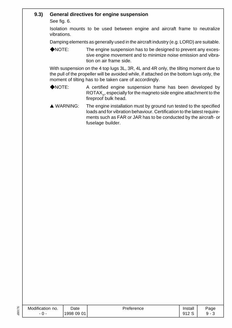
9.3) General directives for engine suspensionSee fig. 6.
Isolation mounts to be used between engine and aircraft frame to neutralizevibrations.
Damping elements as generally used in the aircraft industry (e.g. LORD) are suitable.
NOTE: The engine suspension has to be designed to prevent any exces-sive engine movement and to minimize noise emission and vibra-tion on air frame side.
With suspension on the 4 top lugs 3L, 3R, 4L and 4R only, the tilting moment due tothe pull of the propeller will be avoided while, if attached on the bottom lugs only, themoment of tilting has to be taken care of accordingly.
NOTE: A certified engine suspension frame has been developed byROTAX
®, especially for the magneto side engine attachment to the
fireproof bulk head.
WARNING: The engine installation must by ground run tested to the specifiedloads and for vibration behaviour. Certification to the latest require-ments such as FAR or JAR has to be conducted by the aircraft- orfuselage builder.

Preference Modification no.- 0 -
Page9 - 4
Date1998 09 01
Install912 S d0
0176
Blank page

PreferenceModification no.- 0 -
Page10 - 1
Date1998 09 01
Install912 Sd0
0177
02022
02023
00776 fig. 10
coordinates [mm]location x axis y axis z axis
-160 -196 -82
-160 -212 -113
-192 196 -82
-192 212 -113-408 -196 -82-408 -212 -113-438 196 -82-438 212 -113
Zylinder 1cylinder 1
cylinder 2
cylinder 3
cylinder 4
points of attachment
max. allowable forces (limit load) in (N) in x,y and z axis
1 000
max. allowable bending (limit load) in (N) in x,y and z axis
40
10) Exhaust systemSee fig. 2, 3 and 4.
The shape and execution of the exhaust system isdetermined essentially by the free space available inthe aircraft.
For attaching, the exhaust system two studs M8x23are provided on each cylinder.
Location of the studs:
NOTE: All dimension to point of reference(P).
WARNING: The exhaust system has to be designed by the aircraft or fuselage buildersuch, that the limit loads on the points of attachment will not by exceeded.Additional support of exhaust system may be necessary.
10.1) Requirements on the exhaust systemSee fig. 10.
mean bending radius of exhaust bend : ............. min. 40 mm (1,6 in.)
exhaust bend, inside dia.: .................................. min. 28 mm (1,1 in.)
muffler volume: .................................................. c. 5 l (1,32 US gal)
back pressure at takeoff performance: .............. max. 0,2 bar (2,9 psi.) (readingstaken c. 70 mm (2,76 in.) fromflange connections)
exhaust gas temperature (EGT):(both ignition circuits active) .............................. nominal c. 800° C (1470° F)
max. 850° C (1616° F)max. 880° C (1616° F) at take offperformance (readings taken c.70 mm = 2,76 in. down stream ofexh. flange).
The exhaust gas temperatures (EGT) have tomeasured at the initial engine installation in anaircraft and must be verified in the course of testflights.
WARNING: The exhaust system has to bedesigned and built such, thatthe operating temperatures aremaintained and the max. ex-haust gas temperatures willnever be exceeded.
The 4 exhaust sockets included in the supplyscope have to be used without exception.
ø30
ø27
36

Preference Modification no.- 0 -
Page10 - 2
Date1998 09 01
Install912 S d0
0177
Material of the exhaust sockets: ............................ X 6 CrNiTi 1810 (DIN 1.4541)
Tightening torque of the lock nut M8for the exhaust flange: ............................................. 12-20 Nm (106 -177 in.lb.) Pay
also attention on SI 5 UL 97
ATTENTION: Fit heat shields near carburetors or as required.
Because of the high temperatures occurring, provide suitableprotection against unintentional contact.
ATTENTION: Secure exhaust system by suitable means according to installa-tion.
10.2) General directives for exhaust-systemSee fig. 11.
A exhaust system, especially for universal application has been developed byROTAX®. Certification to the latest requirements to FAR or JAR has to be conductedby the aircraft- or fuselage builder.
The following recommendations should help the aircraft builder to plan a suitableexhaust system.
NOTE: These recommendations derive from years of experience and theresults achieved are generally very good.
A common transversal muffler serving all 4 cylinders and positioned under theengine is favourable.
Distribution of the exhaust gases into 2 separate systems is not recommended.Single mufflers on either side cause power loss and increased noise emission.
The 4 ball joints must be used to avoid damage due to vibration.
Be aware that locked up stresses cause cracks!
Attachment of exhaust bends by springs!
Springs to be secured!
All ball joints have to be greased regularly with heat resistant lubricant (e.g.LOCTITE ANTISEIZE) to avoid gripping and seizing of the joints.
ATTENTION: Vibrations due to improper installation and maintenance is themost common reason for damage of the exhaust system.
The sketch illustrates a possibility how to interconnect the exhaust springs to preventthe vibration of these springs and thus premature wear.
It is also recommended to fill the springs with Silastic for additional damping ofvibrations.
ATTENTION: Appropriate to the installation a vibration damping support for theexhaust system has to be provided on the air frameside.fig. 11
00528

PreferenceModification no.- 0 -
Page11 - 1
Date1998 09 01
Install912 Sd0
0178
11) Cooling systemThe shape, size and location of one or more radiators depend mainly on the space available.
No provision is made for attachment of the radiator(s) on the engine.
11.1) Requirements on the cooling system ATTENTION: All components of the cooling system have to be secured suitably.
WARNING: The size and layout of the cooling system must be designed to keepthe operating temperatures within the specified limits.
Coolant hoses:
temperature durability: ....................................... min. 125°C (257° F)
pressure durability: ............................................ min. 5 bar (73 psi.)
nom. inside dia : ................................................. 25 mm (1 in.)
bending radius: .................................................. min. 175 mm (6,9 in.)
material: ............................................................. Suitable for 100 % Glycol andantifreeze agents. Pay attentionto ozone stability!
NOTE: If installations require a longer distance use aluminium pipes (25mm (1in.) inside dia.) instead of hoses.
11.2) Size and position of connectionsSee fig. 12, 13 and 14.
expansion tank Q with radiator cap W
to radiator E: ................... outside dia. .................. 25 mm (1 in.)slip-on length ............... max. 22 mm (.87 in.)
to overflow bottle R: ........ outside dia. .................. 8 mm (.31 in.)slip-on length ............... max. 15 mm (.59 in.)
fig. 12
00529
1
4
3
2

Preference Modification no.- 0 -
Page11 - 2
Date1998 09 01
Install912 S d0
0178
water inlet bend T: ...... outside dia. .................. 27 mm (1,06 in.)slip-on length ............... max. 19 mm (.75 in.)
NOTE: Choose between four possible fitting positions of water inlet bendT appropriate to specific installation (see fig.). The inlet bend isattached to the water pump by two Allen screws M6x20 and lockwashers. Tighten screws to 10 Nm (90 in.lb.).
ATTENTION: Utilize total slip-on length for hose connection. Secure hoses withsuitable screw clamp or by crimp connection.
11.3) Coolant capacity4 cylinder heads: .................................................... 560 cm3 (.15 gal us)
water pump: ........................................................... 100 cm3 (.03 gal us)
expansion tank: ...................................................... 250 cm3 (.07 gal us)
2 m coolant hose (18 mm inside dia.) : ................. 500 cm3 (.13 gal us)
total coolant quantity in engine:.............................. c. 1400 cm3 (.37 gal us)
110° 105°70°75°
fig. 14
fig. 13
00350
00530

PreferenceModification no.- 0 -
Page11 - 3
Date1998 09 01
Install912 Sd0
0178
11.4) Feasible location of radiatorSee fig. 15.
The expansion tank Q must always be positioned at the highest point of the coolingsystem.
ATTENTION: If necessary, the radiator outlet opening I may be max. 1,5 m( 5 ft.) above or below water inlet bend T on water pump (see fig.15).
NOTE: On the standard engine version the expansion tank Q is fitted ontop of the engine (see fig. 15).
For proper operation of the cooling system the expansion tank Q with pressure capW has to remain for all possible engine positions on the highest point of the coolingcircuit.
Additionally the system needs an overflow bottle U where surplus coolant is collectedand returned back into the circuit at the cooling down period.
NOTE: For proper operation keep hose to overflow bottle as short andsmall as possible.
ATTENTION: To warrant the proper operation of the cooling system the deliveryhead between overflow bottle and expansion tank must not exceed250 mm (10 in.).
Requirements on the overflow bottle U
transparent material
unaffected by temperatures from -40° C (-40° F) to +125° C (257° F)
resistant against 100% Glycol and any other anti freeze agent
possible to vent Y
volume c . 0,5 l (.13 us gal)
NOTE: The overflow bottle ought to be furnished with a label indicatingfunction and content.
WARNING: Ensure that the overflow bottle will never be empty, otherwise airwill be sucked into cooling circuit with ill effect to safe operation ofthe engine.
fig. 1500342
1 2
3
4
5
67
8

Preference Modification no.- 0 -
Page11 - 4
Date1998 09 01
Install912 S d0
0178
11.5) General directives for the cooling systemSee fig. 16.
ROTAX® offers essential parts of the cooling system for this engine such as radiator,
overflow bottle etc. (see spare parts list) in the non-certified state. Certification to thelatest requirements to FAR or JAR has to be conducted by the aircraft or airframebuilder.
In an installation as de-picted with the radiator O ina higher position than the stand-ard supplied expansion tank, a wa-ter accumulator P has to fitted insteadof the expansion tank. Additionally a suitable expansion tank Q has to be installedat the highest point of the cooling circuit.
ATTENTION: The size and type of radiator should be adequate to transferthermal energy of c. 28 kW (26,5 BTU/s) at takeoff power.
NOTE: Assessment data by experience. For troublefree operation at goodairflow a radiator of at least 500 cm2 (78 in2) area has to be used.
The flowrate of coolant in the cooling system can be assumed withc. 55 l/min (16 US gal/min) at 5500 rpm.
Kühler / radiator
Wasserpumpe /water pump
Ausgleichsgefäß /expansion tank
Überlaufgefäß /overflow bottle
Wassersammler /water distributor
fig. 16
00343
91
10

PreferenceModification no.- 0 -
Page12 - 1
Date1998 09 01
Install912 Sd0
0179
attachment points
max. allowable forces (limit load) in (N) in x,y and z axis
2 000
max. allowable moment (limit load) in (Nm) in x,y and z axis
50
min. length of thread engagement (mm)
15
12) Cooling air ductingContrary to the cylinder heads, the cylinders are ram air cooled. Plan cooling air ductingaccording to installation requirement.
WARNING: The cooling air ducting has to be designed and built such, that the operatingtemperatures are kept within the specified limits, warranted even at hotday conditions .
12.1) General directives for ducting of the cooling airSee fig. 2, 3 and 4.
For front installation in a closed fuselage, ducting of cooling air to the cylinders ishighly recommended. In this case a costly horizontal partitioning can be avoided.
NOTE: The engine remains in this case completely on the warm side of theengine compartment and is very well accessible. In special casesa separate cold air supply to the air intake filters has to be provided.
ROTAX® developed especially for this application a non-certified cooling air ducting.Certification to the latest requirement like FAR or JAR has to be conducted by theaircraft builder.
The following recommendations should assist the aircraft builder at the planning ofa suitable cooling air ducting.
NOTE: These recommendations derive from years of experience and theresult achieved are generally very good.
ATTENTION: The cooling air ducting to be adequate to transfer thermal energyof c. 6 kW (5,7 BTU/s) at takeoff power.
required cross section of air duct: ...................... at least 100 cm2 (16 in2)
material:glass fibre reinforced plastic or heat resistant non-inflammable material.
attachment:formlocking on engine case and cylinders
NOTE: In case formlocking attachment won`t be adequate, additionalattachment is possible on two threaded lugs M8 on top side ofengine.
02024
02025
ATTENTION: The stated limit loads are valid only at utilization of min specifiedthread length, and must never be exceeded.
Depth of thread ...................................................... 18 mm (.71 in.).
axis
x axis y axis z axis
-300,0 -30,0 -14,0
-300,0 30,0 -14,0
attachment points

Preference Modification no.- 0 -
Page12 - 2
Date1998 09 01
Install912 S d0
0179
Schraube / screw M5
12.1.1) Cylinder wall temperatureCylinder wall temperature ...................................... max. 190 °C (374 °F)
To verify the efficiency of the cooling system the cylinder wall temperature has to bemeasured. The temperature reading of the cylinder wall can either be taken on topside or on bottom side of cylinder 2. The temperature sensor has to be located on thecylinder wall between the second and third cooling fin.
NOTE: To clamp a thermo couple on the cylinder wall it is recommendedto cut a thread M5 between the cooling fins.
02050

PreferenceModification no.- 0 -
Page13 - 1
Date1998 09 01
Install912 Sd0
0180
13) Lubrication system (oil system)In the standard engine version an oil tank is included. For the closed lubrication circuit an oilcooler and connecting lines are needed as well.
The certification of the oil cooler and connecting lines to the latest requirements such as FARand JAR has to be conducted by the aircraft builder.
No provision has been made for attaching the oil cooler on the engine.
13.1) Requirements on the lubrication system WARNING: The lubrication system has to be designed such that operating
temperatures will not exceed the specified limits.
Oil pressure see fig. 46.
max. ................................................................... 7 bar (at cold start a pressureof up to 7 bar (100 psi) ispermitted)
min. .................................................................... 0,8 bar (12 psi)(below 3500 1/min)
nominal .............................................................. 2,0 ÷ 5,0 bar (29 - 73 psi)(above 3500 1/min)
ATTENTION: At full throttle operation the max. allowed depression at pump inletis 0,3 bar (4,4 psi.) below the ambient pressure. Reading must betaken at a distance of max. 100 mm (4 in.) before pump inlet.
Oil temperature
nominal-operating temperature.......................... c. 90 ÷ 110° C (190 ÷ 250° F)
min. 50° C (120° F),
max. 130° C (266° F)
WARNING: At operation below nominal oil temperature formation of conden-sate in the lubrication system might influence oil quality.
Oil lines
Temperature durability: ...................................... min . 140° C (285° F)
Pressure durability: ............................................ min. 10 bar (145 psi.)
Bending radius: .................................................. min. 70 mm (2,76 in.)
Minimum inside dia of oil lines in reference to total length
length up to 1m (3') ........................................... min. 11 mm ø (.43 in.)
length up to 2 m (6'-6 in.) ................................... min. 12 mm ø (.47 in.)
length up to 3 m (10') ......................................... min. 13 mm ø (.51 in.)
ATTENTION: The suction lines must be secured against folding.

Preference Modification no.- 0 -
Page13 - 2
Date1998 09 01
Install912 S d0
0180
Venting line of oil tank
See fig. 17 and 20.
Route the line without kinks and avoid sharp bends.
NOTE: Water is a by-product of combustion. Most of this water willdissipate from the combustion chamber with the exhaust gases.
A small amount will reach the crankcase and has to be disposedthrough the venting line of oil tank via oil return line.
The venting line must be routed in a continuous decline or furnished with a drainbore at it's lowest point to drain possible condensate.
The venting line has to be protected from any kind of ice formationin the condensate. Protection by insulation, or routing in a hose withhot air flow or by furnishing venting line with a bypass opening Qbefore passing through cowling W.
13.2) Size and position of connectionsSee fig. 18, 19 and 20.
oil pump inlet nipple E. outside dia .................. 13,2 mm slip-on length .................................................... max. 21 mm (.83 in.)
nipple for oil return line R. ... outside dia. ...... 13,5 mm (.53 in.)slip-on length ... max. 24 mm. (.95 in.)
Tightening torque of Banjo bolt T M16x1,5 ...... 35 Nm (310 in.lb.).
TO
EE fig. 18
fig. 19
fig. 17
00532
02590
00081
45
3

PreferenceModification no.- 0 -
Page13 - 3
Date1998 09 01
Install912 Sd0
0180
oil tank
Inlet Y and outlet U with screw connection
outside dia. ........................................................ 12 mm (.47 in.)
slip-on length ..................................................... max. 24 mm (.95 in.)
Tightening torque ............................................... 25 Nm (220 in.lb.).
NOTE: Inlet and outlet, standard version with swivel joint O and 90°connecting bend.
venting nipple I. ............. outside dia. ................ 8 mm (.32 in.)
slip-on length ........... max. 15 mm (.59 in.)
ATTENTION:Utilize total slip-on length for hose connection. Secure hose withsuitable screw clamp or by crimp connection.
OUT
fig. 20
00533
6
8
99
7
IN

Preference Modification no.- 0 -
Page13 - 4
Date1998 09 01
Install912 S d0
0180
13.3) Feasible position and location of the oil tankSee fig. 21.
The longitudinal axis z3 to be parallel to z-axis of the system of coordinates.
Tolerated deviation of parallelism: ......................... ± 10°
NOTE: Above notice is valid for both planes.
The oil tank has to be positioned in it's z-axis such that the oil level Q is alwaysbetween 0 and -400 mm on the z-axis.
WARNING: At higher location of the oil tank oil might trickle through clearancesat bearings into crankcase during longer periods of engine stop. Iffitted too low it might badly effect the oil circuit.
Install the oil tank free of vibrations.
Oil tank cover, oil drain plug and oil filter to be easily accessible.
+z
-z
+y
+z3
-z3
max
. 400
mm
-yP
fig. 21
00534
1

PreferenceModification no.- 0 -
Page13 - 5
Date1998 09 01
Install912 Sd0
0180
13.4) Feasible position and location of the oil coolerSee fig. 20 and 21.
On principle the oil cooler has to be installed below the engine. See fig.21.
ATTENTION: If this position is not be practicable, install with connectionsupwards i.e. in positive direction on z-axis. See fig. This will preventan unintentional draining of the oil cooler at longer engine stop.
ATTENTION: The oil cooler has to be designed to dissipate c. 8 kW (7,58 BTU/s) heat energy at takeoff power.
NOTE: From years of experience we recommend an oil cooler size of atleast 160 cm2 (25 in2), provided that air flow is adequate.
WARNING: Adhere to limits of oil temperature.Consult chapters 7.1 and 13.1.If need be take appropriate measures like changing size of radiator,partial covering of oil cooler etc.
13.5) Filling capacity Oil quantity without oil cooler and connecting lines, 3l (0,8 US gal) min. 2l (0,5 US
gal).
13.6) Venting of the lubrication systemSee fig. 21
Venting of the lubrication system is extremely important for operation and life ofengine and therefore it has to be followed meticulously.
Fill oil tank with approx. 2 Litres (0,53 gal. US) of motor oil. See chapter 10.2.3 ofOperator’s Manual.
WARNING: For safety’s sake, switch off ignition and remove ignition key.
Disconnect suction hose from oil tank and fill the oil hose with oil utilizing a suitablefunnel. By cranking the engine with a few turn of the propeller oil will be sucked in bythe oil pump.
ATTENTION: If in the suction line of the oil pump an oil cooler is installed thisprocedure will take a bit longer as the cooler has to filled with oil first.
Reconnect oil suction line on tank and crank engine with starter but with ignition‘OFF’ until steady min. oil pressure is indicated on oil pressure gauge.
Switch on ignition and start engine and observe oil pressure.
The oil pressure must rise within 10 seconds to at least 2 bar (30 psi.). If not stop theengine instantly and vent suction line between oil tank and oil pump again as statedabove.
After positive oil pressure indication start engine under observation of oil pressure.After short idling, stop engine and replenish oil to max. mark on tank. Never overfill,otherwise oil would escape through venting bore during operation. At oil level checkthe max. mark must not be exceeded.
WARNING: Always observe the engine whilst running from a safe place.

Preference Modification no.- 0 -
Page13 - 6
Date1998 09 01
Install912 S d0
0180
Blank page

PreferenceModification no.- 0 -
Page14 - 1
Date1998 09 01
Install912 Sd0
0181
14) Fuel systemOn the standard engine version the two BING constant depression carburetors are alreadyfitted and the fuel lines to manifold installed.
Installation of the system from the fuel tank to the inlet of engine-driven fuel pump has to beestablished by the aircraft- or fuselage builder.
The assembly consist of the following items:
fuel tank
coarse filter
water trap
fire cock
electrical supplementary pump, if arrangement is without gravity feed (electric fuel pumpwith proper capacity and maximal 0,35 bar operating pressure)
pressure gauge
fuel lines as required
The fuel pump will be supplied complete with fuel lines and connections.
ATTENTION: A fine filter with mesh size 0,1 mm has to be installed upstream of the fuelpump.
Dry type filter elements (paper filter) are not permitted as they could absorbwater and thus reducing flowrate.
ATTENTION: Certification of components not included in the supply scope have to beconducted to the latest requirements such as FAR and JAR by the aircraftbuilder.

Preference Modification no.- 0 -
Page14 - 2
Date1998 09 01
Install912 S d0
0181
14.1) Requirements on the fuel system WARNING: Design and layout of the fuel system has to warrant engine
operation within the specified limits.
Fuel pressure: see fig. 23
nominal pressure of mechanical fuel pump: .......... 0,3 bar (4,4 psi.)
tolerated fuel pressure range: ................................ max. 0,4 bar (5,8 psi.)
min. 0,15 bar (2,2 psi.)
WARNING: Fuel pressure in excess of 0,4 bar can lead to an override of thefloat valve with subsequent engine stop.
NOTE: Readings of the fuel pressure are taken at the pressure gaugeconnection Y on fuel manifold R.
Delivery rate:
min. 35 l/h (8,2 US gal/h) of mechanical or electric fuel pump.
Fuel lines:
According to valid certification or national specifications.
ATTENTION: For prevention of vapour locks, all the fuel lines on the suction sideof the fuel pump have to be insulated against heat in the enginecompartment and routed at distance from hot engine components,without kinks and protected appropriately.
At very critical conditions e.g. problems with vapour formation thefuel lines could be routed in a hose with cold air flow.
Fuel filter: see fig. 22
Coarse filter: ...................................................... on fuel tank as per valid certifica-tion
Fine filter: ........................................................... in the feed line between fuel tankand fuel pump, mesh size 0,1mm (.004 in.).
NOTE: The integrated filter in the fuel pump is with mesh size 0,3 mm (.012 in.).
Fuel temperature:
To prevent vapour locks temperatures in excess of 36° C are not permissible in thevicinity of fuel lines, float chamber and such.

PreferenceModification no.- 0 -
Page14 - 3
Date1998 09 01
Install912 Sd0
0181
coordinates [mm]
x axis y axis z axis
-385,0 -50,0 ca.110clamp block
14.2) Definition and size of connectionSee fig. 2, 3, 4 and 24.
position of z4 axis of the fuel manifold:
NOTE: Dimensions always from point of reference (P).
return line to tank T:
outside dia. ........................................................ 7 mm (.28 in.)
slip-on length: .................................................... max. 17 mm (.67 in.)
pressure gauge connection Y:
outside dia. ........................................................ 6 mm (.24 in.)
slip-on length: .................................................... max. 17 mm (.67 in.)
ATTENTION: At loosening or tightening of the banjo bolt U (tightening torque 10Nm = 90 in.lb.) support the fuel manifold appropriately.
NOTE: The connection nipple T is furnished with an orifice I (0,35 mm= 0,014 in.) essential for operation of the fuel system.
ATTENTION: Utilize max. slip on length. Secure hoses with suitable screwclamps.
02772
fig. 23
zum Tank /to fuel tank
zum Manometer /to fuel pressure gauge
z4
von der Pumpe /from fuel pump
zum Vergaser /to carburetor
zum Vergaser /to carburetor
5
8
7
6
fig. 24 02064
9
3
10

Preference Modification no.- 0 -
Page14 - 4
Date1998 09 01
Install912 S d0
0181
Blank page

PreferenceModification no.- 0 -
Page15 - 1
Date1998 09 01
Install912 Sd0
0182
reference point P2
max. allowable forces (limit load) in (N) in x,y and z axis
60
max. allowable bending moments (limit load) in (Nm) in x,y and z axis
4
coordinates [mm]
carburetor for x axis y axis z axis
cylinder 1/3 -553 180 25
cylinder 2/4 -521 -180 25
7 mm
267
87
0
fig. 25
P2
106
P1 P1 P1
P2
P1
fig. 26
00538
02028
00316
02027
13 4
2
15) CarburetorSee fig. 25.
The carburetors on the standard engine are already attached by a flexibly flange. Onlyconnections of the Bowden cable for throttle and starting carburetor as well as fuelconnections have to be established.
WARNING: The carburetor flange assembly has to carrythe weight of the carburetor and intake system.Ensure that the screw of the clamp is posi-tioned on the underside as supplied and thegap between the clamp plates is 7 mm.
15.1) Requirements on the carburetor WARNING: The carburetor is positioned above the exhaust socket. Therefore
fit a suitable plate under the carburetor serving as trip pan and heatshield.
ATTENTION: The carburetor venting lines have to be routed into the air intakesilencer as specified and approved by ROTAX®. Consult alsochapter 16.
After the fuel lines are connected on the carburetor put paint on banjo bolt R of swiveljoint.
The certification to the latest requirements such as JAR or FAR has to be conductedby the aircraft builder.
15.2) Dimensions for installation and limit loadSee fig. 2, 3, 4, 2 and 27.
centre position of carburetor socket (P1) of the respective carburetor:
NOTE: All dimensions topoint of reference (P)
limit load on point of reference P2
ATTENTION: The specified limit loads must never be exceeded.

Preference Modification no.- 0 -
Page15 - 2
Date1998 09 01
Install912 S d0
0182
connection QQQQQ for air filter or intake silencer
outside dia.: ....................................................... 50 mm (2 in.)
slip-on length: .................................................... 12 mm (.47 in.)
connection for throttle actuation WWWWW
connection on throttle lever: ............................... set screw M 5x12
tightening torque: ............................................... 4 Nm (35 in.lb) (suitable for 1,5mm = .06 in. steel wire)
action travel: ...................................................... 65 mm (2,6 in.)
actuating force: .................................................. min. 1,5 N (.3 lb.)max. 8 N (1,8 lb.)
limit load: ............................................................ 20 N (4,5 lb.)
connection for starting carburetor (choke) actuation EEEEE
connection on choke lever: ................................ clamping nipple 6 (suitable for1,5 mm steel wire)
action travel: ...................................................... 23 mm (.9 in.)
actuating force: .................................................. min. 10 N (2,2 lb.)max. 24 N (5,4 lb.)
limit load: ............................................................ 100 N (22 lb.)
15.3) General directivesSee fig. 26 and 27.
The choke shaft R is marked T. This mark has to pointtowards cable engagement Y.
WARNING: Route Bowden cable in such a waythat carburetor actuation will not beinfluenced by any movement of engineor air frame, thus possibly falsifying idlespeed setting and carburetor synchroni-sation.
Adjust Bowden cable such that throttle and choke can be fullyopened and closed. Use Bowden cable with minimized friction sothat the spring on the throttle can open the throttle completely.Otherwise a stronger return spring or a cable with pull-push actionwould have to be used.
The throttles have to be actuated by two synchronous workingcables.
NOTE: Spring opens throttle.
WARNING: With throttle lever not connected the carburetor will remain fullyopen. Therefore never start the engine without connecting theBowden cables first.
5,22,2
ø6,
7
fig. 27
00541
3
4
5
6

PreferenceModification no.- 0 -
Page16 - 1
Date1998 09 01
Install912 Sd0
0183
16) Air intake systemSee fig. 28.
The intake system is determined essentially by the demands of engine and of the acceptablenoise emission on the intake side. In the standard ROTAX
® engine supply volume an airbox
is included.
Performance data as specified and limits of operation can only be warranted by employmentof the genuine ROTAX® airbox.
If it will be necessary to use a different airbox or a modified genuine ROTAX® airbox, for
reasons of installation the actual airbox employed has to be sent to ROTAX® for verification.
Nevertheless, the certification of the modified airbox to the latest requirements such as FARor JAR has to be conducted by the aircraft builder.
16.1) Requirement on the intake system WARNING: Carburetor icing is a common reason for engine trouble. In the
airbox offered by ROTAX® provisions have been made for intake airpreheating.
If an airbox of not ROTAX® origin is used provisions for preheatingthe intake air have to be made to prevent formation of ice in theintake system.
Preheating of the intake air will lead to a reduction of engineperformance by low of nature!
WARNING: All intake components have to be secured against loss.
The certification to the latest requirements such as FAR or JAR have to be conductedby the aircraft builder.
Air filter :
ATTENTION: A minimum flow rate of 220 m3/h has to be warranted for allconditions.
The pressure loss in intake ducting must not exceed 2 hPa (0.03psi).
WARNING: Use only filter elements which will not tend to restrict flow when incontact with water.
Air filter:
material: ............................................................. four-fold cotton fabric,
face: ................................................................... covered with aluminium screen,
total filter area: ................................................... at least 1400 cm2 (220 in2)
Airbox: See fig. 28.
volume: .............................................................. at least 2,5 l (.66 US gal)
outline dimension: .............................................. see fig. 28.

Preference Modification no.- 0 -
Page16 - 2
Date1998 09 01
Install912 S d0
0183
Draining lines
WARNING: To connect the draining lines is absolute necessary otherwiseflooding fuel from leakage could end up on the exhaustsystem. RISK OF FIRE!
- These lines have to be routed such that in case of damage the surplus fuel will bedrained to a suitable place.
- Route the lines without kinking and avoid narrow bends.
- The lines must be installed with continuous inclination.
- The lines have to be protected against any kind of blockage, for instance byformation of ice.
ATTENTION: If the draining lines are closed or blocked, fuel could end up on theexhaust system. RISK OF FIRE!
Nipples TTTTT for connection of draining lines
Outside diameter .................................................... 6 mm (.24 in.)
Slip-on length ......................................................... 17 mm (.67 in.)
ATTENTION: The float chamber venting must never be exposed to velocitypressure.
Provide connection to take readings of manifold pressure E.
Provide connections for temperature sensor R.
Outside diameter .................................................... 6 mm (.24 in.)
Slip-on length ......................................................... 17 mm (.67 in.)
ATTENTION: If the engine has been installed without employment of the ROTAX®
engine frame which includes also support of the airbox, thanprovide an appropriaty support for the airbox.
NOTE: Make sure that the air intake tubes of the airbox for fresh air andpreheated air are connected correctly.
NOTE: Fig. 28 shows the genuine ROTAX® airbox.
Bild 28
02051
1
3
22
4 4
02663
1
Ø 9
3
Ø 52
Ø 60
456
5
1
COLD(FRESH AIR)
WARM(PREHEATED AIR)

PreferenceModification no.- 0 -
Page17 - 1
Date1998 09 01
Install912 Sd0
0184
30A
Batterie +battery +
U
IGL B
50A
2,5
16
2,5
0,51,5
1,5
0,5
CL+BRGG
2,52,5 0,5
2,5
0,75
22 000µF(25 V)
4
br
br
ge
ge
ws/ges
bl/ge
Batterie +battery +
+12 V
Batterie+, Verbrauche rbattery +, consumer
nicht im Lieferumfangenthalten / optional
B
A
1,5 kurze Leitung / short wire
Batterie + Verbraucherbattery + consumer
1,5
17) Electric systemSee fig. 29.
The engine is supplied with the wiring completed and ready to operate. Only the followingconnections to the aircraft have to be established.
integrated generator Q Þ external rectifier-regulator W
electronic module E Þ shorting button R (grounding)
electric starter T Þ start relay Y
if required:
rev-counter pick-up U Þ electric rev-counter I
auxiliary generator(optional extra) O Þ consumer (battery)
ATTENTION: The connections have to be completed by the aircraft builder in accordanceto effective certification and wiring diagram.
The electromagnetic compatibility (EMC) and electromagnetic interfer-ence (EMI) is greatly affected by the wiring and has to be checked for eachinstallation.
WARNING: The supply to the various consumers (e.g. battery) has to be protectedadequately by fuses (consult wiring diagram). When using a fuse too largedamage to electric equipment may result.
Under no circumstances route consumers cables (e.g. battery) side byside with ignition cable. Induction could cause problems.
Colour code: ws Þ white bl Þ blue ge Þ yellow br Þ brown
Attention:The difference between batteryvoltage and rectifier regulator in-put terminal C should be lessthan 0,2V. In this area cables ofsufficient cross section but asshort as possible, should beused.
Attention:Do not interupt circuit betweenTerminal C and +B of rectifier-regulator during engine run, asotherwise charging will stop.
During engine stop break circuitbetween battery and terminal Cto avoid discharge of battery.
fig. 29
00542
Q
W
E
R R
T
Y
U I
O
P
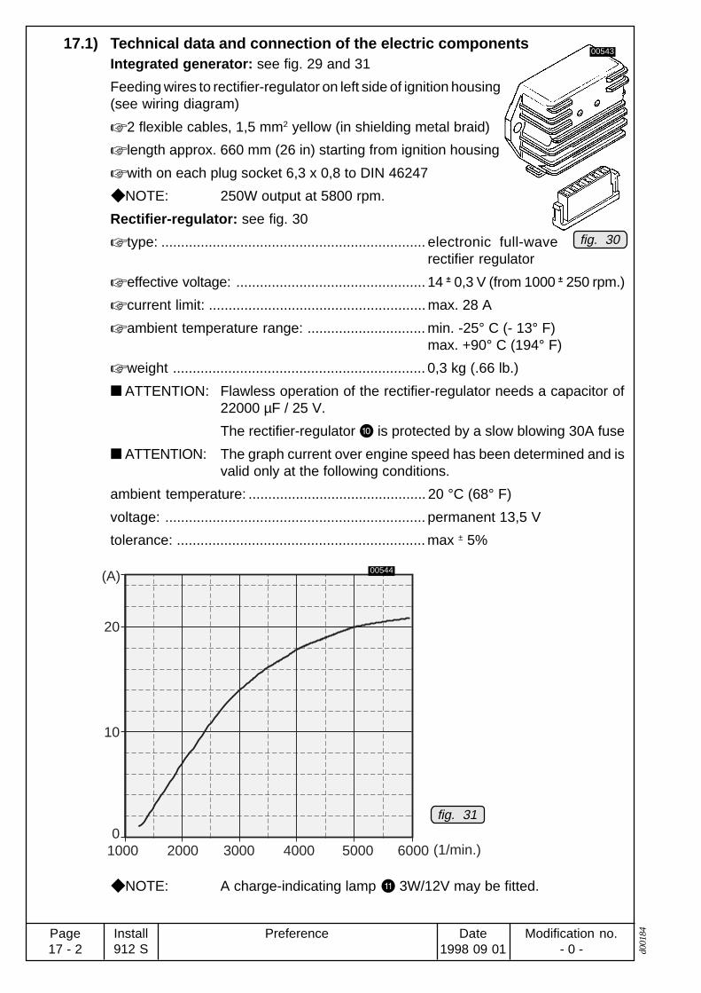
Preference Modification no.- 0 -
Page17 - 2
Date1998 09 01
Install912 S d0
0184
17.1) Technical data and connection of the electric componentsIntegrated generator: see fig. 29 and 31
Feeding wires to rectifier-regulator on left side of ignition housing(see wiring diagram)
2 flexible cables, 1,5 mm2 yellow (in shielding metal braid)
length approx. 660 mm (26 in) starting from ignition housing
with on each plug socket 6,3 x 0,8 to DIN 46247
NOTE: 250W output at 5800 rpm.
Rectifier-regulator: see fig. 30
type: ................................................................... electronic full-waverectifier regulator
effective voltage: ................................................ 14 ± 0,3 V (from 1000 ± 250 rpm.)
current limit: ....................................................... max. 28 A
ambient temperature range: .............................. min. -25° C (- 13° F)max. +90° C (194° F)
weight ................................................................ 0,3 kg (.66 lb.)
ATTENTION: Flawless operation of the rectifier-regulator needs a capacitor of22000 µF / 25 V.
The rectifier-regulator P is protected by a slow blowing 30A fuse
ATTENTION: The graph current over engine speed has been determined and isvalid only at the following conditions.
ambient temperature: ............................................. 20 °C (68° F)
voltage: .................................................................. permanent 13,5 V
tolerance: ............................................................... max ± 5%
NOTE: A charge-indicating lamp 3W/12V may be fitted.
fig. 30
fig. 31
0
10
20
1000 2000 3000 4000 5000 6000
(A)
(1/min.)
00544
00543

PreferenceModification no.- 0 -
Page17 - 3
Date1998 09 01
Install912 Sd0
0184
Ignition switches (on-off switch): see fig. 29
type: ................................................................... two separate, suitable on-offswitches
switching voltage: .............................................. min. 250 V
switching current: ............................................... min. 0,5 A
Feeding lines to on-off switches on the electronic module (see wiring diagram).
1 each flexible cable .......................................... 0,75 mm2, brown
Length approx. 50 mm (2 in.) from electronic modules.
with one each plug connector Sumitomo 6187-1171
NOTE: One each quick-connector assy. for shorting cable supplied loose.
Shorting cable of top electronic module (marked "A") for ignition circuit A.
Shorting cable of bottom electronic module (marked "B") for ignition circuit B.
NOTE: Ignition circuit A serves: top spark plugs of cyl. 1 and 2lower spark plugs of cyl. 3 and 4
Ignition circuit B serves: top spark plugs of cyl. 3 and 4lower spark plugs of cyl. 1 and 2
ATTENTION: The electromagnetic compatibility (EMC) and electromagneticinterference (EMI) depends essentially on the shorting cablesused.
Min. section area: 2x 0,75 mm2 (shielded flexible cable, shieldingbraid on both ends grounded).
ATTENTION: The metal base of each ignition switch must be grounded to air craftframe.
Electric-starter: see fig. 29 and 32
output: ................................................................ 0,6 kW
feeding lines to electric starter on right side of ignition housing.
plus terminal T: .................................................. M6 screw suitable for cable eyesto DIN 46225
grounding: .......................................................... via engine block
ATTENTION: Duration of starting period is limited. Consult Operator's Manual,Chapter "engine operation".
fig. 32
00545
5

Preference Modification no.- 0 -
Page17 - 4
Date1998 09 01
Install912 S d0
0184
Start relay: see fig. 29 and 33
nominal voltage: ................................................. 12 V
control voltage: .................................................. min. 6 Vmax. 18 V
switching current: ............................................... max. 75 A (permanent)max. 300 A (for 1 sec.)
ambient temperature range: .............................. min - 40° C (-40° F)max. +100° C (214° F)
weight: ............................................................... 0,145 kg (.32 lb.)
current connections: .......................................... M6 screw suitable for cableeyes to DIN 46247
control wiring: ..................................................... plug connector 6,3x0,8 suitablefor plug socket to DIN46247
grounding: .......................................................... via housing
ATTENTION: Activation of start relay limited to short duration. Over a period of 4min. operation, the duty cycle is 25%.
fig. 3300546

PreferenceModification no.- 0 -
Page17 - 5
Date1998 09 01
Install912 Sd0
0184
1/min. / rpm.
2000 3000 4000 5000 6000 7000 8000 n Generatorrpm. alternator
(A)
10
20
30
40
50
1000 1500 2000 2500 n Propellerrpm. propeller
9
Auxiliary generator O (as option): see fig. 29, 34 and 35.
output: ................................................................ max. 600 W DC at 6000 rpm.
voltage: .............................................................. 14,2 ÷ 14,8 V
ambient temperature range: .............................. min. - 30° C (-22° F)max. +90° C (194° F)
NOTE: Voltage regulator is integrated in the generator
Feeding wiring to auxiliary generator located on the outside of propeller gear
plus terminal q: ................................................. M 6 screw suitable to cable eyesto DIN 46225
grounding: .......................................................... via engine block
control wiring : ................................................ via supplied standard plug(Sumitomo 6111-2568)
ATTENTION: The current over speed graph has been determined and is effectiveonly at the following conditions:
ambient temperature: ............................................. 20 °C (68° F)
voltage: .................................................................. permanent 13,5 V
tolerance: ............................................................... ± 5%
NOTE: The speed of the auxiliary generator is 1,23 times crankshaft speedor 3 times propeller speed.
fig. 35
fig. 3400547 00548
5
5
5

Preference Modification no.- 0 -
Page17 - 6
Date1998 09 01
Install912 S d0
0184
Drehzahl 6000 1/min. (Last 100 Ω) /rpm. 6000 1/min. (load 100 Ω)
0
(+V)
(-V)
5
5
10
10
1 Umdr. 360° /1 turn 360°
Connection of electric rev-counter: see fig. 29, 37, 38, 39 and 40.
Feeding wiring to electric rev-counter on left side of ignition housing (consult wiringdiagram)
material: ............................................................. 2 flexible cables 0,5 mm2, white/yellow and blue/yellow (in insu-lation wrap)
length: ................................................................ approx. 600 mm (24 in.) startingfrom ignition housing
NOTE: ROTAX® developed especially for this application a non-certifiedelectric rev-counter. Certification to the latest requirements such asFAR or JAR has to be conducted by the aircraft builder.
ATTENTION: The graphs depicting output signals have been determined and areeffective only at the following conditions.
ambient temperature: ............................................. 20° C (68° F)
tolerance: ............................................................... ± 5%
The pick-up for the rev-counter generates one pulse per revolution. Pulse shape andpulse voltage as per recordings (oscillogram).
Drehzahl 500 1/min. (Last 100Ω) /rpm. 500 17min. (load 100 Ω)
0
(+V)
(-V)
1
1
2
3
2
3
4
1 Umdr. 360°/1 turn 360°
Drehzahl 500 1/min. (Last 100 kΩ) /rpm. 500 1/min. (load 100 kΩ)
0
(+V)
(-V)
5
5
10
15
10
15
1 Umdr. 360° /1 turn 360°
1 Umdr. 360° /1 turn 360°
Drehzahl 6000 1/min. (Last 100 kΩ) /rpm. 6000 1/min. (load 100 kΩ)
0
(+V)
(-V)
50
50
100
100
150
fig. 38
fig. 40
00550
00551
00549
00552
fig. 37
fig. 39

PreferenceModification no.- 0 -
Page17 - 7
Date1998 09 01
Install912 Sd0
0184
Battery:
ATTENTION: To warrant reliable engine start use a battery of at least 16Ah.
Electromagnetic compatibility (EMC/EMI):
Electromagnetic interference (EMI) and lightning:
The engine complies with the EMI and lightning requirements per DO-160C, sections18, 20-22 as noted in the following paragraphs.
Emission
Conducted RF Interference:
Narrowband and broadband emissions meet RTCA DO160C Section 21-1 Cat.B(AZ) except in the frequency range of 150kHz ÷ 2MHz where emissions are up to20dB higher than allowable limits.
Radiated RF Interference:
Narrowband and broadband emissions meet RTCA DO160C Section 21, Fig. 21-6and 21-7, Cat. B except in the frequency range of 190kHz - 2MHz where emissionare up to 35dB higher than allowable limits.
WARNING: Consult the manufacturer if further interpretation is needed. Theseexceedances do not affect engine operation.

Preference Modification no.- 0 -
Page17 - 8
Date1998 09 01
Install912 S d0
0184
Blank page

PreferenceModification no.- 0 -
Page18 - 1
Date1998 09 01
Install912 Sd0
0185
18) Propeller driveThe propeller in tractor-or pusher arrangement has to be fitted on the propeller flange inaccordance to current certification. As required utilize one of the three possible pitch circlediameters (P.C.D.) on the flange.
Certification of the propeller sizing and arrangement to the latest requirement such as FARor JAR has to be conducted by the aircraft builder.
WARNING: Never run the engine without a propeller installed as engine would suffersevere damage by overspeeding.
Never fit propeller directly on crankshaft.
18.1) Technical data:See fig. 41.
direction of rotation of the prop flange: .............. counter clockwise, looking to-wards face of flange
location: ............................................................. see system of coordinates
attachment of propeller on prop shaft flange:
P.C.D 75 mm (2,95 in.): . ................................... 6 bolt holes of 8 mm dia
P.C.D 80 mm (3,15 in.): . ................................... 6 bolt holes of 11,5 mm dia
P.C.D 101,6 mm (4 in.): 3 . .................................. 6 bolt holes of 13 mm dia. andhub dia 47 mm
ratio of gear reduction:. ...................................... 2,43
max. torque: ....................................................... 130 Nm (96 ft.lb.)
max. permitted out-of-balance on a prop: .......... max. 0,5 gm
max. extension of propeller shaft: ...................... 120 mm (4 3/4“).
ATTENTION: No modifications of propeller shaft permitted.
P.C.D.101,6
P.C.D. 80
dia.12
,975
dia.13
,025
8,5
Pdia.
47
-
P.C.D
. 75
dia. 1
1,5
dia. 8
+0,2
02763
fig. 41

Preference Modification no.- 0 -
Page18 - 2
Date1998 09 01
Install912 S d0
0185
Blank page

PreferenceModification no.- 0 -
Page19 - 1
Date1998 09 01
Install912 Sd0
0186
19) Vacuum pump
19.1) Technical data:See fig. 2, 3, 4 and 42.
Type: ...................................................................... Airborne 211 CC, drive via pro-peller gear
location of the necessary connection Q and W on the vacuum pump
connections
thread size: ........................................................ 5/8“ 16 T.P.I.
tightening torque: ............................................... hand tight and tighten up by max.1,5 turn with ringspanner.
Effective thread length: .......................................... max. 17 mm (.67 in.)
net weight: ......................................................... 0,8 kg (1,76 lb.)
power input: ....................................................... max. 300 W
ATTENTION: Take note of manufacturer’s specifications.
NOTE: Speed reduction ratio from engine to vacuum pump is 1,842, i.e.the vacuum pump speed is 0,54 of the engine speed.
ATTENTION: The certification to the latest requirements such as FAR or JAR hasto be conducted by the aircraft builder.
fig. 42
1
2
02029
00255
coordinates [mm]
connection x axis y axis z axis
1 226 0 982 293 0 98

Preference Modification no.- 0 -
Page19 - 2
Date1998 09 01
Install912 S d0
0186
Blank page

PreferenceModification no.- 0 -
Page20 - 1
Date1998 09 01
Install912 Sd0
0187
20) Hydraulic governor for constant speed propeller
20.1) Technical data:See fig. 2, 3, 4 and 43.
Type: ...................................................................... Woodward governor A210786(for engine type S3 only), drivevia prop gear
Location of centre of connection (P3):
cable connection: ............................................... 5 mm dia. hole (0,2 in.)
cable travel: ....................................................... approx. 54 mm (2,13 in.)
actuating force: .................................................. approx. 3 N = .67 lb(during operation at max.speed)limit load 6 N = 1,35 lb
power input: ....................................................... max. 600 W
operating pressure: ............................................ max. 30 bar = 435 psi
net weight: ......................................................... 2,7 kg (6 lb)
NOTE: Speed reduction ratio from engine to hydraulic governor is 1,842i.e. the hydraulic governor rotates with 0,54 of engine speed.
P3
90°15°
5
min.Steigung /minimum pitch
max
. Ste
igun
g /
max
imum
pitc
h
38
7
P3
fig. 43
02031
00556
coordinates [mm]
x axis y axis z axis
-373 -10 51
Centre P3

Preference Modification no.- 0 -
Page20 - 2
Date1998 09 01
Install912 S d0
0187
Blank page

PreferenceModification no.- 0 -
Page21 - 1
Date1998 09 01
Install912 Sd0
0188
21) Connections for instrumentationThese connections to be established in accordance to certification and/or national specifica-tions.
The certification for connections and connection lines have to be conducted by the aircraftbuilder for the latest requirement like FAR and JAR.
For notes regarding the electric rev-counter consult the chapter 17 "Electric system".
21.1) Sensor for cylinder head temperature:See fig. 2, 3, 4 and 44.
location: ............................................................. in the cylinder head of the cylin-ders 2 and 3
connection: ........................................................ plug for socket 6,3x0,8 to DIN46247
grounding: .......................................................... via engine block
graph of sensor resistance over temperature
ATTENTION: The graph resistance over temperature has been determined, andis effective at the following conditions only.
ambient temperature: ............................................. 20° C (68° F)
tolerance: ............................................................... ± 10%
NOTE: ROTAX® recommends the temperature indication VDO instrument“VDO 310.274/082/017“ with an indicating range of 50° to 150° C(120° F - 300° F).
fig. 44
12010080604020 140 160
1200
1000
(Ω)
(°C)
800
600
400
200
0
02030
00557
coordinates [mm]cyl. head (botton)
x axis y axis z axis
2 -200,0 241,0 -157,03 -387,0 -241,0 -157,0

Preference Modification no.- 0 -
Page21 - 2
Date1998 09 01
Install912 S d0
0188
21.2) Sensor for oil temperature:See fig. 2, 3, 4, 44 and 45.
location: ............................................................. oil pump housing
marking W: marked with "TO" on oil pump flange
ATTENTION: To avoid any mix-up withindication wiring, mark thisparticular cable also with"TO".
position of the temperature sensor Q on the oil pump flange:
connection of sensor wiring: .............................. plug for socket 6,3 x 0,8 to DIN46247
grounding: .......................................................... via engine block
graph of sensor resistance over temperature
ATTENTION: The graph resistance over temperature has been determined, andis effective at the following conditions only.
ambient temperature: ............................................. 20° C (68° F)
tolerance: ............................................................... ± 10%
NOTE: ROTAX® recommends the temperature indication VDO instrument
“VDO 323.801/010/001“ with an indicating range of 50° C to 150°C (120° F ÷ 300° F).
fig. 45
TO
fig. 44
12010080604020 140 160
1200
1000
(Ω)
(°C)
800
600
400
200
0
02590
02032
00557
1
2
coordinates [mm]
x axis y axis z axis
-115 46 -150
point of support -
p u n k t

PreferenceModification no.- 0 -
Page21 - 3
Date1998 09 01
Install912 Sd0
0188
21.3) Oil pressure pick-up:See fig. 2, 3, 4, 46 and 47.
location: ............................................................. oil pump housing
position of connection on oil pressure pick-up Q:
connection of pick-up wiring: ............................ single pole screw connection forcable eye 3 to DIN 46225
grounding: .......................................................... via engine block
graph of resistance over pressure
ATTENTION: The graph resistance over pressure has been determined, and iseffective at the following conditions only.
ambient temperature: ............................................. 20° C (68° F)
voltage: .................................................................. 12 V
tolerance: ............................................................... max. ± 5%
200(Ω)
(bar)
150
100
50
0108642
fig. 47
fig. 46
00226
02033
00226
1
coordinates [mm]
x axis y axis z axis
ca. -100 75 ca. -150
point of connection

Preference Modification no.- 0 -
Page21 - 4
Date1998 09 01
Install912 S d0
0188
21.4) Mechanical rev-counter or hour-meter:See fig. 2, 3, 4, 48 and 49.
location: ............................................................. ignition housing Q
direction of rotation of the rev-counter shaft W: .. clockwise, see fig.
position of rev-counter drive:
installation dimensions: ...................................... see fig.
reduction ratio: ................................................... i = 4 i.e. 1/4 of engine speed
NOTE: A flexible shaft for the mechanical rev-counter is readily availablefrom ROTAX
®.
20.5) Monitoring of the intake manifold pressure connection on compensating tube: .................... outside dia. 7 mm (.276 in.)
slip-on length: .................................................... max. 17 mm (.67 in.)
NOTE: The reading of the manifold pressure in inches Hg is taken inthe compensating tube connecting the two intake manifolds.Consult chapter 16) of intake system.
ATTENTION: To ensure trouble free operation of the vacuum gauge it will benecessary to install a trap for gasoline condensate betweenengine and instrument.
P4 M18x1,
1
1
2,6
2
2,6fig. 49fig. 48
02034 00562
00560
1
2
coordinates [mm]
x axis y axis z axis
-465 87 -160
point of engagement
P4

PreferenceModification no.- 0 -
Page22 - 1
Date1998 09 01
Install912 Sd0
0189
22) Preparations for trial run of engine WARNING: Prior to engine start and operation review all instructions stated in the
Operator's Manual.

Preference Modification no.- 0 -
Page22 - 2
Date1998 09 01
Install912 S d0
0189
Blank page

PreferenceModification no.- 0 -
Page23 - 1
Date1998 09 01
Install912 Sd0
0190
23) ROTAX Authorized Distributors for Aircraft Engines
Edition: 1998 01 011) E U R O P E
AUSTRIA:HB - FLUGTECHNIK GES.M.B.H.
Dr. Adolf Schärf Str. 44A-4053 HAIDTel.: 07229 / 79104/79117, Fax: 07229 / 79104 15Contact person: Ing. Heino Brditschka
BULGARIA:GERGANOV - AIRCRAFT EINGINES LTD.
25B-Post 20, 23 peh. Shlp. polk Blvd.BG-6100 KAZANLAKTel.: 431 / 27 247, Fax: 431 / 23 777Contact person: Radosslav D. Gerganov
CROATIA / former YUGOSLAVIA(except SLOVENIA):
SHAFT D.O.O.B.L. Mandica 161 aHR-54000 OSIJEKTel. + Fax: 054 / 760 - 046Contact person: Ing. Ivan Vdovjak
CZECHIA:TEVESO S.R.O.
Skroupova 9441CS-50002 HRADEC KRALOVETel.: 049 / 56 30 127, Fax: 049 / 56 30 226E-mail: [email protected] persons: Ing. Samal / Ing. Halek
DENMARK / THE NETHERLANDS:FLIGHT-CENTER
FlugplatzD-27777 GANDERKESEE, GERMANYTel.: 04222 / 3789, Fax: 04222 / 6042E-mail: [email protected] person: Robert Heilig
FINLAND / NORWAY/ SWEDEN/ESTONIA/ LATVIA / LITHUANIA
BOMBARDIER NORTRAC LTD.Box 8039, FIN-96101 ROVANIEMITel.: 16 320 8111; FAX: 16 320 8200E-mail: [email protected] person: Tommi Ristimella
FRANCE / BELGIUM / MONACO /LUXEMBURG:
MOTEUR AERO DISTRIBUTION11 Blvd Albert 198000 MONACOTel.:7 93 30 17 40, Fax: 7 93 30 17 60E-mail: [email protected] person: Patrick Coyette
GERMANY:for postcodes 0-5-6-7-8-9:
FRANZ AIRCRAFT ENGINES VERTRIEB GMBHAm Eckfeld 6e, D-83543 ROTT AM INNTel.: 08039 / 90350, Fax: 08039 / 9035-35E-mail: [email protected] person: Eduard Franzfor postcodes 1-2-3-4:
FLIGHT-CENTERFlugplatzD-27777 GANDERKESEETel.: 04222 / 3789, Fax: 04222 / 6042E-mail: [email protected] person: Robert Heilig
GREAT BRITAIN / IRELAND / ICELAND:SKYDRIVE LTD.
Burnside, Deppers BridgeLEAMINGTON Spa. CV 33 OSUTel.: 1926 / 612 188, Fax: 1926 / 613 781E-mail: [email protected] person: Nigel Beale
GREECE / CYPRUS:KINISI
Ellis 1 str. , GR-14563 KIFISSIATel.: 01 / 620 8611; Fax: 01/ 625 0026Contact person: Michael Poulikakos
Nick Siganos
HUNGARY:HALLEY
Baktai út 45, P.O. Box 425H-3300 EGERTel.: 36 / 313-830, Fax: 36 / 320-208
ITALY / MALTA:ICARO MOTORI S.R.L.
Via Emilia, 61/BI-27050 REDAVALLE (PV)Tel.: 0385 / 74 591, Fax: 0385 / 74 592E-mail: [email protected] person: Corrado Gavazzoni
POLAND:FASTON LTD.
ul. Szeroka 2PL-05-860 PLOCHOCINTel.: + Fax: 22 / 40 01 96Contact person: Wojtek Madry, Manager
ROMANIA:S.C. BERIMPEX S.R.L.
Str. Dr. Taranu Grigore No. 8, Ap. 2, Sector 5R-76241 BUCHARESTTel.: 1-410 90 03; Fax: 1-410 9020E-mail: [email protected] person: Dr. Christian Berar
SLOVAKIA:TEVESO S.R.O.
Skroupova 441CS-50002 HRADEC KRALOVETel.: 049 / 56 30 127, Fax: 049 / 56 30 226E-mail: [email protected] persons: Ing. Samal / Ing. Halek
SLOVENIA:PIPISTREL d.o.o.
Strancarjeva Ul. 115270 AJDOVSCINATel. 065 63 873, Fax: 065 61 263E-mail: [email protected] person: Ivo Boscarol
SPAIN / PORTUGAL:AVIASPORT S.A.
Almazara 11E-28760 TRES CANTOS (MADRID)Tel.: (91) 803 77 11, Fax: (91) 803 55 22E-mail: [email protected] person: Mariano de Castro

Preference Modification no.- 0 -
Page23 - 2
Date1998 09 01
Install912 S d0
0190
SWITZERLAND / LIECHTENSTEIN:FRANZ AIRCRAFT ENGINES VERTRIEB GMBH
Am Eckfeld 6e, D-83543 Rott am Inn, GERMANYTel.: 08039 / 90350, Fax: 08039 / 9035-35E-mail: [email protected] person: Eduard Franz
TURKEY:KLASIK HALI A.S.
Klasik Hali is Merkezi, Bozkurt Caddesi No. 25/A35230 Kapilar / IZMIR TURKEYTel.: (232) 441 4911; Fax: (232) 445 1285Contact person: Tahir Önder, President
2) A M E R I C A
CANADA:ROTECH RESEARCH CANADA, LTD.
S 22 C39 RR6 STN MAIN6235 Okanagan Landing Rd.VERNON, B.C., V1T 6Y5Tel.: 250 / 260-6299, Fax: 250 / 260-6269E-mail: [email protected]
NORTH / MIDDLE / SOUTH AMERICA:KODIAK RESEARCH LTD.
P.O. Box N 7113Marlborough House Cumberland StreetNASSAU, BAHAMASTel.: 242 / 356 5377, Fax: 242 322 6784E-mail: [email protected]
3) A U S T R A L I AAIRCRAFT ENGINE DISTRIBUTORS PTY. LTD.
P.O. Box 84, Boonah, QLD. 4310Tel.: 07 5463 2755, Fax: 07 5463 2987E-mail: [email protected] person: Jim Fenton
BERT FLOOD IMPORTS PTY. LTD.P.O. Box 61, LILYDALE, VICTORIA 3140Tel.: 03 / 9735 5655, Fax: 03 / 9735 5699E-mail: [email protected] person: Bert Flood
NEW ZEALAND:TIPPINS INTERNATIONAL
P.O. Box 192, TuakauSOUTH AUCKLANDTel.: 09 / 233 - 4898, Fax: 09 / 233 - 4798E-mail: [email protected] person: Murray Tippins
4) A F R I C A
EGYPT:SALEM BALLOONS
40 Talaat Harb St., CAIROTel.: (2) 2991 946 / (2) 3038 214, Fax: (2) 3038 214E-mail: [email protected] person: Weaam Salem, General Manager
ANGOLA / BOTSWANA / LESOTHO /MADAGASCAR / MALAWI / MOZAMBIQUE/ NAMIBIA / SOUTH AFRICA / SWAZILAND/ ZAMBIA / ZIMBABWE:
AVIATION ENGINES ANDACCESSORIES (PTY) LTDPrivate Bag X10021, Edenvale 1610, South AfricaTel.: 011 / 455 4203/4/5/6/9, Fax: 011 / 455 4499E-mail: [email protected] person: Mike Blyth
5) A S I A
CHINA / HONG KONG / MACAO:DUEN MU CO.
Room 1603, Telford House16 Wang Hoi Road, Kowloon BayKowloon, HONG KONGTel.: 2756 5725, Fax: 2754 4774E-mail: [email protected] person: W. C. Choi
CIS:AVIAGAMMA JSCo.
P.O. Box 51, 125 057 MOSCOWTel.: 095 / 158 31 23, Fax: 095 / 158 6222E-mail: [email protected] person: Vladimir Andriytschuk
General Director
INDIA:GREAVES LIMITED
22-A, JanpathNEW DELHI - 110 001Tel.: 11/338 50 61/338 26 53 (Dir.), Fax:11/37 82 553Tlx.: 031-62663E-mail: [email protected] person: Wg Cdr S.N. Chhabra
Divisional Manager
INDONESIA / MALAYSIA / PHILIPPINES /SINGAPORE / THAILAND:
TPA PTE LTD.12 Little Road, #02-01/02Lian Cheong Industrial BuildingSingapore 536986Tel.: (65) 289 8022Fax: (65) 289 1011E-mail:[email protected] person: Chan Nyuk Lin
IRAN:TASHAR CO. LTD.
54 Khaled Eslamboli Ave., TEHERAN 15117Tel.: 21 / 871 4787 / 872 3222, Fax: 21 / 872 2260Contact persons: Morthesar Sadjat
Jusufi Nejadan
ISRAEL:CONDOR-AVIATION INDUSTRIES LTD.
P.O. Box 1903, 14 Topaz st.Cesaria 38900Tel.:06 / 6265080, 90 / 50-290189Fax: 06 / 62650 95E-mail: [email protected] person: David Viernik
J A P A N :JUA, LTD.
1793 Fukazawa, Gotemba CitySHIZUOKA PREF 412Tel.: 550 / 83 8860, Fax: 550 / 83 8224Contact person: Yoshihiko Tajika, President
KOREA:HWA YOUNG MEDICAL & SCIENCE CO.
Office address:401 KeumKang Building1439-1, Seocho 1 dong, seocho-ku, SEOUL 137-071Tel.: 02 / 3472-0271-5,Fax: 02 / 3472-0276 (02/3471-4753)Contact person: John Lee, PresidentMailing address:SL Kang NamP.O. Box 918, SEOUL

PreferenceModification no.- 0 -
Page23 - 3
Date1998 09 01
Install912 Sd0
0190
PAPUA NEW GUINEA:BERT FLOOD IMPORTS PTY. LTD.
P.O. Box 61, LILYDALE, VICTORIA 3140AUSTRALIATel.: 03 / 9735 5655, Fax: 03 / 9735 5699E-mail: [email protected] person: Bert Flood
TAIWAN:TAIWAN MAXIEM INDUSTRIES
7/1 Tung Feng Street, TAIPEI, 10 651Tel.: 2 / 2704 6163, Fax: 2 / 2702 84 85Contact person: Lester Lin
UNITED ARAB. EMIRATES:AL MOALLA
P.O. Box 7787ABU DHABITel.: 2 / 723 248, Fax: 2 / 788 073E-mail: [email protected] person: Hussain Al Moalla
