for space exploration r. joseph cassady, 1robert … · for space exploration r. joseph cassady,...
TRANSCRIPT
RECENT ADVANCES IN NUCLEAR POWERED ELECTRIC PROPULSION
FOR SPACE EXPLORATION
R. Joseph Cassady, 1 Robert H. Frisbee, 2 James H. Gilland, 3 Michael G. Houts, 4 Michael
R. LaPointe, 4 Colleen M. Maresse-Reading, 2 Steven R. Oleson, _ James E. Polk, 2 Derrek
Russell, 6 and Anita Sengupta 2
Corresponding author." Michael LaPointe, NASA Marshall Space Flight Center,
Huntsville, AL 35812. [email protected], Phone 256-961-7555
ABSTRACT
Nuclear and radioisotope powered electric thrusters are being developed as primary in-
space propulsion systems for potential future robotic and piloted space missions. Possible
applications for high power nuclear electric propulsion include orbit raising and
maneuvering of large space platforms, lunar and Mars cargo transport, asteroid
rendezvous and sample return, and robotic and piloted planetary missions, while lower
power radioisotope electric propulsion could significantly enhance or enable some future
robotic deep space science missions. This paper provides an overview of recent U.S. high
power electric thruster research programs, describing the operating principles, challenges,
and status of each technology. Mission analysis is presented that compares the benefits
and performance of each thruster type for high priority NASA missions. The status of
space nuclear power systems for high power electric propulsion is presented. The paper
concludes with a discussion of power and thruster development strategies for future
radioisotope electric propulsion systems,
1Aerojet Corp., Redmond, CA2 Jet Propulsion Laboratory, Pasadena. CA3 Ohio Aerospace Institute, Cleveland, OH4NASA Marshall Space Flight Center, Huntsville, AL5NASA Glenn Research Center, Cleveland, OH6Northrop Grumman Space Technology, Redondo Beach, CA
https://ntrs.nasa.gov/search.jsp?R=20070031879 2018-06-21T09:34:15+00:00Z

Ke.cz/words:Spacepropulsion,electricpropulsion,electrostatic,electromagnetic,plasma,
nuclear
NOMENCLATURE
ALFA z = Advanced Lithium-Fed Applied-field Lorentz Force Accelerator
ATLO = Assembly, Test and Launch Operations
= Magnetic Field (Tesla)
Bi = Bismuth (propellant)
= Electric field (V/m)
ETRU = Extraterrestrial Resource Units
eV electron-Volt
go Gravitational acceleration at sea level, 9.81 m/s 2
FSP Fission Surface Power
GPHS General Purpose Heat Source
H20 Water (propellant)
IMLEO Initial Mass in Low Earth Orbit
1NSRP Intra-agency Nuclear Safety Review Panel
Isp Specific Impulse (s)
j = Current density/A/m 2)
] = Current (A)
JIMO = Jupiter Icy Moon Orbiter
Li = Lithium (propel/ant)
Mf = Final spacecraft mass (kg)
Mi = Initial spacecraft mass (kg)
MMRTG =
MPDT =
NH3
NSTAR
NuPIT =
PIT
PPU
q
RTG =
SRG
T
Ue
UHV
V
VHITAL =
Xe
AV
Multi-Mission Radioisotope Thermal Generator
Magnetoplasmaciynamic Thruster
Propellant mass flow rate (kg/s)
Ammonia (propellant)
NASA Solar Electric Power Technology Application Readiness
Nuclear electric Pulsed Inductive Thruster
Pulsed Inductive Thruster
Power Processing Unit
Particle charge (Coulomb)
Radioisotope Thermal generator
Stifling Radioisotope Generator
Thrust (N)
Exhaust velocity Ira/s)
Ultra High Voltage
Applied voltage (V)
Variable Specific Impulse Thruster with Anode Layer
Xenon (propellant)
Specific mass (kg/kWe)
Electric potential (V)
Mission velocity incremem (m/s)

1. INTRODUCTION
Chemical propulsion is at present the only viable technique for lifting payloads from
Earth into orbit. Once in space, however, electrically powered thrusters using ionized gas
propellants can provide significant advantages over chemical engines for several types of
missions. The propellant exhaust velocity produced by chemical combustion is typically
well below the optimum exhaust velocity for most missions of interest. By decoupling the
energy source from the propellant, electric propulsion (EP) systems can provide
substantially higher propellant velocities than chemical engines, albeit at lower thrust.
Compared with chemical engines, the higher exhaust velocities offered by electric
propulsion can clramatically reduce the amount of propellant required to perform a given
mission. The savings in propellant mass can be used to lower mission costs by reducing
the vehicle class needed to launch a given payload, or by increasing the amount of
payload mass delivered to orbit by a given launch vehicle.
A variety of electric propulsion technologies have been in commercial use for several
years, and over 160 satellites now flying in earth orbit employ some form of electric
propulsion. Current electric propulsion systems operate at average power levels of several
watts to a few kilowatts, but research into higher power electric thrusters is underway to
support more demanding potential space science and exploration missions. These
potential future missions include orbit raising and station keeping for large platforms, the
transport of cargo to sustain the human exploration and colonization of the moon and
Mars, asteroid rendezvous and automated sample return missions, robotic deep space
exploration, and at very high power, fast piloted missions to Mars and the outer planets.
The following section provides an introduction to electric propulsion, outlining the major

typesof thrustersandtheirprinciplesof operation.A briefoverviewis thenprovidedof
thekeycomponentsthatmakeupanuclearelectricpropulsionsystem.Following this
background, the status of several recent U.S. high power electric thruster research and
development programs is discussed, and thruster options are compared for various high
priority NASA missions. The status of nuclear fission development programs relevant to
nuclear electric propulsion is briefly described, and the review concludes with a detailed
discussion of low power radioisotope electric propulsion systems considered for robotic
deep space exploration.
2. ELECTRIC PROPULSION FUNDAMENTALS 1
Unlike conventional chemical rockets, in which chemicals react to heat a propellant, electric
propulsion systems use electricity in the form of applied electric fields, currents, and/or magnetic
fields to accelerate a propellant for thrust. Options for electric propulsion thrust generation
include simple electrical heating and expansion of neutral gas propellants (electrothermal
acceleration); acceleration of charged ions using static electric fields (electrostatic acceleration);
and acceleration of current-carrying quasi-neutral plasma using electromagnetic Lorentz forces
(electromagnetic acceleration). As discussed below and in later sections, some electric propulsion
systems employ more than one of these acceleration mechanisms. Different systems may require
continuous or pulsed electrical power, and each EP technology provides unique benefits and
challenges. The inherent physics of each thruster type determines its performance regime, which
must be matched to mission requirements. However, by decoupling the power source from the
propellant, all electric propulsion systems are capable of accelerating propellant to significantly
higher exhaust speeds (uo) than chemical engines. As noted earlier, this corresponds to a
significant reduction in the required propellant mass, as shown by the rocket equation:
1 James Gilland, Ohio Aerospace Institute fiames.h.zilland@m'c.nasa._ov)
AV
Mf =e-_- (1)Mi
where Mf is the final spacecraft mass at the destination, Mi is the initial spacecraft mass
(including propellant), and AV is the change in spacecraft velocity required to perform
the mission. By increasing the propellant exhaust velocity relative to the mission AV, a
higher fraction of the initial spacecraft mass can be delivered to the destination. It is this
feature that makes electric propulsion particularly advantageous for difficult, high AV
missions, such as robotic science misstons to the outer planets and large cargo m_ssions
in support of human space exploration.
Electric propulsion system performance, in particular engine thrust, is limited by the
amount of power that can be imparted to the propellant. EP systems require an electric
power supply, which is carried on-board the spacecraft throughout the mission. The mass
of the power supply reduces the spacecraft mass budget that can be allocated to the
payload. Unlike chemical rockets, an EP thruster must accelerate not only the payload
and propellant, but also the thruster power system. As discussed below, the mass of the
power system, and the inherent scaling of thrust to power in electric propulsion systems,
results in typically low spacecraft accelerations on the order of 10 .3 m/s z.[ 1] Electric
thrusters must generally operate for an extended period of time to provide the required
spacecraft velocities.
2.1 EP Figures of Merit
ro determine the performance of an EP thruster for a gxven mission, multiple aspects
of the propulsion system must be considered. A successful mission is defined by both
payload delivery and by mission time, and reducing the propellant mass by increasing the

exhaust velocity is just the first step in determining the effectiveness of the propulsion
system. The performance of an electric propulsion system, which includes the on-board
power system, can be defmed by a set of four parameters: specific impulse (Isp), thrust
efficiency 01), specific mass (c0, and lifetime.
Specific impulse (I_p) is defined as the thrust per unit weight of propellant flow, measured at sea
level:
T u_I_ = .-7--- = (2)
mg0 go
where m is the propellant mass flow rate, T is the engine thrust (thu.), and go is the acceleration
due to gravity at sea level. Following common usage, the exhaust velocity is typically expressed
as a specific impulse value. Trades to reduce propellant mass and increase power system mass for
a ftxed mission mass and trip time typically lead to a range of optimum Ispvalues which
maximize the delivered payload.J2]
Thrust efficiency 01) is the ratio of kinetic power useful for thrust to the electrical
power input to the thruster:
-_uoT 2t-I_pg0Tn - (3)
JV JV
where the electrical power is the product of total current (J3 and voltage (V) input ro the thruster.
For a given I_ and input power, higher efficiency indicates greater thrust and increased vehicle
acceleration, which in mm reduces mission trip times.
Specific mass (c_) is the ratio of the power and propulsion system mass to the
electrical power generated. This is usually stated in units ofkg/kWe. Lower specific
mass provides a lighter vehicle and greater acceleration.
Lifetime is the length of time the EP thruster can operate before failure. EP thrusters typically
have material surfaces in direct contact with hot plasma, and damage can result from heating,
sputtering_orelectricarcing.BecauseofthelowaccelerationprovidedbyEPsystems,lifetimes
ontheorderofmonthsoryearsaretypicallyrequired.If operationallifetimesaretooshortthen
replacementthrusterswouldberequiredduringthecourseofthemission,whichincreasessystem
massandcomplexity.
2.2 Categories of Electric Propulsion
As noted, electric propulsion relies on the conversion of electric power into directed
thrust. This can be accomplished in a variety of ways, ranging from simple electrothermal
heating of the propellant gas to more complex electrostatic and electromagnetic
acceleration of ionized gas propellants.
Electrothermal Thrusters
Electrothermal propulsion systems are typically low power, direct current devices that
heat propellant gas either indirectly using a resistively heated solid element (resistojet), or
directly by passing current through a gas (arcjet). Both thruster technologies are mature
and have successfully flown on spacecraft for several decades.[3] Electrothermal heat
addition limits these devices to specific impulse values less than 2000 s, which are useful
for near-Earth orbit applications but are generally inadequate for space exploration
missions beyond low Earth orbit. As such, these devices are not generally considered for
nuclear electric power mission applications, and will not be considered further in this
review.
Electrostatic Thrusters
Electrostatic propulsion systems, which apply a static electric potential to accelerate
charged ions, are one of the oldest and most effective means of particle acceleration. Ions
areacceleratedto anexhaustspeeduedeterminedbytheparticlemass(mi),charge(q),
andappliedpotential(q_):
uo= (4)m_
The two fundamental types of electrostatic accelerators developed for spacecraft
propulsion are the gridded ion thruster and the Hall-effect thruster. As discussed below,
each type differs in the means used to generate the accelerating potential, leading to
different performance regunes and technical challenges. Extensive flight experience has
been gained with both types of electrostatic thrusters, and they are widely used for
satellite station-keeping and orbit maneuvering.
Griddedlon Thruster The initial concept for an ion thruster appears in the writings of
both Goddard and Tsiolkovski.[4] As shown in Fig la, the thruster consists of three
essential components: a discharge chamber, a set of accelerating grids, and a neutralizer.
Electrons generated by the hollow cathode are attracted to the positively charged walls of
the discharge chamber and collide with the propellant gas m create plasma; alternative
discharge chamber designs may use inductive [5] or microwave electron cyclotron
resonance ionization techniques to create the plasma.[6,7] The resulting discharge
chamber plasma is magnetically confined by arrays of permanent magnets in a "ring-
cusp" configuration, which serves to extend the residence time of the bombarding
electrons within the chamber.[8] A potential difference on the order of kilovolts is
applied across a set of closely spaced perforated grids located at the downstream end of
the discharge chamber. The large electric field established between the grids accelerates
the ions out of the discharge chamber at high velocity. An external neutralizer cathode,

typicallyasecondhollowcathodemountedoutsideof thedischargechamber,generates
electronsto neutralizethepositivelychargedionexhaustandpreventit fromreturningto
thespacecraft.
Griddedionthrusterstradecomplexityof constructionfor simplicityof operation.
Multiplepowersuppliesarerequiredto operatethedischargechamber,accelerating
grids,andneutralizer.In retuna,theefficiencyandexhaustvelocitiesof thesedevicescan
bequitehigh,asdiscussedin latersectionsof thispaper.Themaximumoperatingcurrent
densityfor agriddedionthrusteris limitedbyChild-Langmulrspacechargeconstraints
andbymaterialerosion.Highvelocitycharge-exchangeionsfromtheexhaustplumecan
remmto impactthegridstructureandsputtermaterialfromthesurfaces,leadingto
progressivegrid erosionandeventualthrusterfailure.[9] Suchissuesleadtotheuseof
relativelylargegridareasfor highpowerthrusteroperation,whichin turn increasesthe
thrusterspecificmass.[10]Additionalinformationonhighpowergriddedionthrusters
andtheir currentdevelopmentstatusispresentedin Section3.1.
Hall-Effect Thruster As their name implies, Hall-effect thrusters take advantage of the
mean Hall drift of charged particles in a direction perpendicular to a set of orthogonal
electric and magnetic fields_ A basic Hall thruster schematic is shown in Fig lb. A radial
magnetic field is created within a discharge channel using concentric magnetic pole
pieces energized by electromagnetic windings. The back of the discharge channel is
biased to positive anode potential, and attracts electrons generated by an extemal hollow
cathode. The axial electric field and radial magnetic field cause the electrons to drift
azimuthally in the strong magnetic field region, effectively increasing the impedance of
the anode-cathode gap to produce a large electrostatic potential. Propellant ions, created
?
by electron impact ionization, remain largely un-magnetized and are electrostatically
accelerated out of the discharge chamber to provide thrust. Unlike gridded ion thrusters,
Child-Langmuir limits do not occur in Hall thrusters, which instead depend on tailored
magnetic field profiles to efficiently ionize and accelerate the propellant ions. As such,
Hall thrusters can operate at higher plasma densities and provide a correspondingly
higher thrust density than gridded ion thrusters. Hall thruster variations, such as the
Thruster with Anode Layer (TAL) and Stationary Plasma Thruster (SPT), primarily differ
in the material composition and length of their discharge channels, which provide
different ionization and acceleration regimes.[11] Hall thruster lifetimes up to 7400 hours
have been demonstrated in low power devices, and lifetimes approaching 8000 hours are
anticipated in high power thrusters[12]. Hall thruster lifetimes are primarily limited by
plasma erosion of the ceramic discharge channel walls. Additional information on high
power Hall thruster technology is provided in Section 3.2.
Electromagnetic Thrusters
Electromagnetic propulsion systems use the Lorentz force that arises from the
Ol_hogonal application of orthogonal currents (j) and magnetic fields (B):
T= (5)
where the integral is taken over the volume occupied by the current-carrying plasma in
the thruster.J2] There are two primary cylindrical topologies used to generate an axial
Lorentz force in electromagnetic thrusters: radial currents acting with azimuthal magnetic
fields (j_B0), or azimuthal currents acting with radial magnetic fields 0aBr). These

mechanisms are embodied by the magnetoplasmadynamie (MPD) thruster and the pulsed
inductive thruster (PIT), respectively.
Magnetoplasmadynamic (MPD) Thruster In an MPD thruster, gas propellant is
typically injected through the thruster backplate. Currents driven between an outer
cylindrical anode and concentric inner cathode by an applied voltage ionize the propellant
and produce a radial current flow between the electrodes. The return current flowing
through the cathode produces an azimuthal magnetic field, which interacts with the radial
current to axially accelerate the plasma, and with the axial current to compress the plasma
toward the centerline (Fig 2a). In this self-field thruster configuration, thrust scales with
current and thruster geometry as T=bJ 2, where b is a geometric parameter and J is the
total current through the thruster. In applied-field MPD thrusters, external magnet coils
are used to apply axial and radial magnetic fields to help stabilize the discharge, or to
provide additional acceleraflng Lorentz forces through interactions with applied radial
currents and azimuthally induced currents within the thruster.[13]
High thrust and a corresponding improvement in MPD thruster efficiency occurs with
high current operation, corresponding to high input power. Laboratory MPD thrusters
typically operate between 100-kW and 10-MW, the latter in pulsed mode to alleviate
ground test facility requirements.[14] The intermittent development and experimental
status of these high power devices limits the available performance data, and a fully
optimized MPD thruster has not yet been developed. Results to date demonstrate that the
primary MPD thruster wear mechanism is the erosion of the central cathode through
sputtering and local arc attachrnents.[15] High power thruster lifetimes of 5000 h to
10000 h are desirable for most mission applications, but have not yet been demonstrated
?
due to ground facility limitations. Recent advancements in the development of high
power MPD thruster technology are presented in Section 3.3.
Pulsed Inductive Thruster (PIT) The PIT (Fig 2b) delivers a high power current pulse
through a fiat, multi-turn coil to generate a strong radial magnetic field, which in turn
induces an azimuthal electric field in the region above the coil. The induced electric field
ionizes a thin layer of injected gas propellant and generates an azimuthal current within
the newly formed plasma; the radial magnetic field interacts with this induced azimuthal
current to provide the accelerating axial Lorentz force. Propellant gas injected through a
fast-acting valve atop a pylon in f_ont of the coil provides a nearly uniform mass layer
over the coil surface prior to the current pulse. A significant benefit of the PIT is its
eleetrodeless operation, which allows the use of various propellants such as oxygen and
other in-situ gases. Because these high temperature and potentially corrosive plasmas do
not come into direct contact with material surfaces, erosion issues are not a serious
concern. However, the PIT is inherently pulsed and may reqmre up to 10 l° discharges for
missions of interest[ 16], necessitating significant advancements in repetitively pulsed
high power switch and circuit technologies. The operation and status of the Pulsed
Inductive Thruster is further described in Section 3.4.
Advanced Thruster Concepts
Advanced plasma propulsion systems which do not fall under the general electric
propulsion categories outlined above are also being investigated. Of current interest is the
use of plasma waves to heat magnetized plasma, which is then expelled through a
diverging magnetic field (magnetic nozzle). In general, propellant is injected into a
dielectric walled chamber; a radiofrequency antenna surrounds the chamber, and an
j,
external magnetic field coil generates the magnetic field necessary for plasma wave
propagation. Radio waves directed at the plasma by the antenna are absorbed by ions or
electrons, depending on the chosen frequency. For resonance heating, the applied
electromagnetic fields are tuned to the natural cyclotron frequencies of the ions or
electrons. In collisional heating, the electromagnetic fields cause the particles to
oscillate, and energy is delivered through collisions with other particles. In either case,
the wave energy is converted into plasma thermal energy, and the thermal energy is
converted into kinetic energy in the expanding magnetic field. These concepts are at a
very low level of development, and their performance has not yet been measured. Issues
remain concerning the efficiency of plasma production and expansion, as well as the
system level design and integration of such concepts onto spacecraft. However, such
electrodeless concepts do offer the potential for long life, high specific impulse operation.
Two representative concepts are shown in Fig 3; the ECR thruster, which uses electron
cyclotron resonance heating [17], and the VASIMR thruster, which uses ion cyclotron
resonance (ICR) heafmg.[18] Due to their lower level of technical maturity, these
concepts are not described further in this review article.
3. NUCLEAR ELECTRIC PROPULSION SYSTEMS 1
The total vehicle and mission performance of a nuclear electric propulsion system
strongly depend on the characteristics of the nuclear power system.[ 19] In particular, the
specific mass, c_, of the power system tends to dominate that of the electric propulsion
system. As described in Section 2.1, the total system ct determines the overall vehicle
acceleration and therefore the trip time and payload fraction capabilities. Minimization of
1James Gilland, Ohio Aerospace Institute (]ames.h.gilland_grc.nasa._ov)

systemc_requiresan optimization of the total NEP power and propulsion system, the
principal components of which are outlined below.
3.1 NEP Component Technologies
The fundamental requirement of a nuclear electric propulsion system is to convert the
thermal energy of the reactor into directed kinetic energy of the propellant. To
accomplish this task in space requrres systems to handle the useful converted energy as
well as the waste energy. The components to convert heat to electricity, and reject the
waste power, are described below.
A typical nuclear electric propulsion system is shown schematically in Fig 4. The
essential NEP components are the reactor, power conversion system, heat rejection
system, and power management and distribution (PMAD) system. These primary
components and their key performance parameters, as well as the interplay between
components in NEP system designs, are discussed below.
Reactor
As the heat source for the power generation system, the reactor must generate power at
a high temperature for a long period of time. High temperature is desirable to maximize
the thermodynamic efficiency of the total system. Because heat rejection in space is to a
fixed background temperature, the Carnot efficiency of the power system is determined
by the source temperature. Since heat rejection is by radiation alone, the performance of
the heat rejection system is also very sensitive to the peak operating temperature of the
cycle. Space reactor design temperatures ranging from 900 to 1500 K have been
considered, i20]
The requirement for long duration operation stems from the nature of low thrust
electric propulsion missions, which typically operate continuously over the entire life of
the mission. Most NEP missions of interest have durations of 1 to 10 years, with the
possible reuse of the vehicle driving the required lifetime to the multiyear regime. The
reactor lifetkne requirement also drives another reactor design characteristic, the fuel
burn-up fraction. This is the percentage of the fissile fuel that can be used without
affecting reactor performance or safety due to the creation of radioactive byproducts.
The technology challenge in these conflicting requirements is to provide long life at high
temperatures. This is further discussed in Section 6.0.
Power Conversion
The principal power conversion systems proposed for space nuclear power include
both static systems, such as thermoelectric or thermionic converters, and dynamic
systems such as Brayton, Rankine, and Stifling engines.[21 ] As with the reactor system,
these high performance components require operation at high temperature over perhaps
tens of thousands _fhours. Power conversion efficiency is a factor of both the inlet and
outlet temperatures, and significant materials issues, such as strength and dimensional
stability, arise from these requirements.
Heat Rejection
The waste energy from the reactor, power conversion system, electric thruster, and
vehicle electronics must be rejected to space through radiation. The size and mass of the
space radiator system are dependent on two key factors: the amount of waste heat to be
rejected, and the temperature of the radiator. The power conversion efficiency increases

with lower rejection temperatures, which reduces the amount of heat to be radiated away.
But the radiator area increases with lower rejection temperature, resulting in a larger mass
for the radiator system. These factors lead to an inverse and competing relationship
between efficiency and radiation temperature, which in turn impacts the size and mass of
the radiator system. Because the heat rejection system mass is a significant and often
dominant portion of the overall NEP system mass, design trades are required to minimize
the total mass based on the relative masses of the reactor and radiator systems.
Power Management and Distribution
Power switching and transmission from reactor to thruster become particular
challenging for high (> 10 kWe) power electric propulsion systems. Desirable
characteristics for PMAD systems include system reliability over multiple cycles, safely
switching high voltage or high current for use by the electric propulsion system, efficient
power processing and transmission to reduce waste heat, and low system mass to reduce
total system ct. A particular concern in PMAD designs is the maximum allowable
operating temperature for the power electronics. State-of-the-art electronics operate at
lower peak temperatures than the rest of the power conversion system, necessitating a
larger radiator area to reject waste heat. To integrate the power system to the electric
thruster, additional issues of AC versus DC generation and transmission, and high voltage
versus high current transmission, must be considered when designing the overall PMAD
system.[22]
4.RECENT ADVANCES IN HIGH POWER ELECTRIC PROPULSION
In 2003, NASA established the Prometheus Power and Propulsion Office to advance
the state of the art in nuclear power and propulsion to meet future NASA mission
requirements. Key to these efforts was the development of high power electric thruster
technologies that, combined with space nuclear power sources, could provide the
foundation for these bold new exploration missions.J23] Mission attributes enabled by
high power NEP technologies include greater launch window flexibility, enhanced
spacecraft maneuverability at the destination planetary system, more sophisticated active
and passive remote sensing capabilities, and greatly increased science data return
rates. The following sections provide an overview and status of these recent high power
NEP development activities.
4.1 Ion Thruster Technology Development for the Jupiter Icy Moons Orbiter
Project 1
The first mission proposed under the Prometheus project was the Jupiter Icy Moons
Orbiter (JIMO), which focused on the potential development and use of a 100-kW class
spacecraft propelled by electric thrusters. The proposed JIMO mission had two principle
objectives: to tour and characterize three icy moons of Jupiter (Callisto, Ganymede, and
Europa), and to demonstrate nuclear electric propulsion (NEP) flight system technologies
for future planetary and solar system exploration missions. [24] The final requirements for
J1MO were still under review by independent government and industry teams when JIMO
was cancelled in 2005. Prior to cancellation, however, the top-level electric propulsion
system characteristics were identified. The requirements included power levels of 20-kW
1 Steven Oleson, NASA Glenn Research Center (steven.r.oleson(_,nasa._0v)

to 50-kW per thruster, specific impulse values of 2000 m 9000 s; system operation for 6
to 10 years; radiation tolerance to the Jupiter environment; and demonstration of
technology, maturity prior to Preliminary Design Review (PDR). The latter requirement
necessitated that all development models (breadboard hardware, computer models, etc.)
must have been demonstrated, all major technology risks and manufacturing issues
resolved, and detailed plans to accumulate system life data were to be written and
approved prior to PDR. Given these constraints, gridded ion thrusters were selected for
the JIMO mission baseline design due to their maturity, efficiency, demonstrated
operational lifetime, and ability to provide the high specific impulses required by such
high energy missions.
JIMO Technoloav Challen2es for Ion Provulsion
While the ion propulsion system appeared m be the best option for the JIMO
spacecraft, the daunting mission requirements introduced several major new development
challenges. Table 1 compares the propulsion technology needs for JIMO with present ion
thruster technology, as represented by the NASA Solar Electric Power Technology
Application Readiness (NSTAR) thruster recently flown on the NASA Deep-Space 1
spacecraft.J25] The table identifies the technology challenges with respect to each electric
propulsion subsystem, and highlights the technology areas that required improvement for
the JIMO mission. Proposed technology solutions that address each of these challenges
are also listed in the table.
JIMO Ion Thruster Develooment
In 2002 NASA published a Research Opportunities in Space Science (ROSS)
solicitation, which contained the topic "High Power Electric Propulsion for Near-Term
NuclearSystems".Twoproposalsfor ionthrusterdevelopmentwereawarded:theHigh
PowerElectricPropulsion(HIPEP)ionthruster,andtheNuclearElectricXenonIon
System0ffEXIS) ion thruster. Initially awarded through the In-Space Propulsion Office,
these high power electric propulsion development projects were transferred to the
Prometheus Project office, and subsequently to the JIMO project. The HIPEP and NEXIS
projects are discussed below, together with other key development activities undertaken
as part of the JIMO project.
High Power Electric Propulsion System gHIPEP) The goal of the HIPEP effort, led
by the NASA Glenn Research Center, was to develop and demonstrate a 25-kWe ion
thruster operating at a specific impulse of approx'maately 8000s. The HIPEP thruster was
designed to include either microwave or hollow-cathode discharge sources and
neutralizers, and a rectangular discharge chamber and grid geometry that could
potentially scale more easily scaled with power than cylindrical engine designs.[26]
The JIMO-HIPEP team explored various plasma production options, including DC
hollow cathode and AC microwave discharges.[27] Both approaches were used during
the HIPEP project, demonstrating that either option can be used with the rectangular
chamber design. Using the microwave source, the HIPEP thruster was operated up to 16
kW, with power limited by the available microwave supply. Operated with hollow-
cathode sources (Fig 5a), the thruster ran at discharge powers up to 40 kW. Thruster
efficiencies exceeded 72% for specific impulse values between 6000 s and 10,000 s, and
reached over 75% at peak power. The rectangular HIPEP thruster shape enhances the
packaging of multiple thrusters on a single spacecraft; multiple thrusters installed next to
one another will minimize structural elements, and provide a dense cluster of aligned

beams.Therectangularshapealsoallowsthethrustchamberandgridsto beeasilyscaled
withoutextensiveredesign.Earlythrusterdesignsusedcurvetitaniumgridsto
demonstrateelectrostaticperformance;latertestssuccessfullyincorporatedflat pyrolitic
graphitegridsto increasethrusterlifetime.Operatedwithpyrolitic grids,theHIPEP
thrusterisprojectedto achieve100kg/kWof xenonpropellantthroughput,atboth8000s
and6000sspecificimpulse.[28-32]Analyticresultsalsoprojectthatthesefiat grids,with
aproperlydesignedHIPEPflight thruster,cansurvivetherigorsof launchwith adequate
margin.J33]
BasedonthesuccessoftheHIPEPlabmodeltesting,workbeganontwo development
modelsto addressvariousform,fit, andfunctionchallengesbasedontheROSS
solicitationrequirements.Thefirst modelwasusedin a2000hrweartest,whichwas
successfullycompletedin 2005.[34-36]. Althoughshortcomparedto therequired6-10
yearthrusterlifetimesexpectedfor JIMO,this initial testbeganto assessthelonglife
featuresof thethrusteranddemonstratedtheability of thedesignto operateovera long
period.A secondHIPEPthrustermodelwasalsoconstructed,andsawlimitedusein
performanceandintegrationtestingpriorto JIMOprojecttermination.[37]
Nuclear Electric Xenon 1on System _EXIS) Thruster The NEXIS thruster effort, led
by the NASA Jet Propulsion Laboratory, focused on the development of a 20-kWe ion
engine to operate at 7500 s specific impulse. State of the art performance and life
assessment tools were used in the thruster design. The primary goal of the effort was to
improve thruster life by improving the discharge cathode and neutralizer, and by
developing and using carbon composite grids.J38] Additional details of the NEXIS
project are described ha [38-40] and references therein.
The NEXIS team demonstrated a 65-cm laboratory model ion thruster (Fig 5b), as
well as a long life reservoir cathode that operated successfully over a 2000-hr wear
test. [41] The NEXIS thruster was operated at power levels up to 27 kW, and achieved up
to 81% efficiency for specific impulse values between 6500s and 8700s. The large
circular thruster incorporated a multi-magnet ring design, and successfully operated with
both flat and dished carbon-carbon (C-C) grids. Analysis of the dished C-C grids
indicates they will survive launch loads. The NEXIS thruster, operated with C-C grids, is
projected to provide the 100-kg/kW xenon throughput margin specified for the JIMO
mission. [38]
Based on the success of the laboratory model thruster tests, development models were
built to address various form, fit, and function challenges. The first development model
completed performance testing and was used in a 2000 hr wear test. [39] Although again
short compared to the required 6-10 year lifetime expected for JIMO, this test began to
assess the long life features of the NEXIS thruster and demonstrated the ability of the
thruster to operate for long periods of fmae. A second NEXIS design model successfully
completed a vibration test at full Prometheus-1 proto-flight levels, prior to JIMO project
termination.
High Voltage Propellant Isolators and Insulators
Electrical isolation between the propellant tanks held at spacecraft potential and the
charged ion thruster discharge chamber has always raised concerns of reliability and
durability. In addition, the need to sustain high voltage differences between adjoining
thruster components while mechanically supporting the thruster body and ion optics
requires a trade between size, weight, structural considerations, and material durability.

Ultra high voltage (UHV) propellant isolators and electrical insulators will be necessary
for the higher power, high specific impulse ion thrusters envisioned for Prometheus
missions. Electrical isolation up to 6500-V will be required, necessitating 15000-V stand
offs to assure adequate safety margins. To address this issue, an array of UUV xenon
propellant isolators and insulators were constructed and evaluated during the J1MO
project to quantitatively measure limits and safety margins.J42] Shadow shield designs,
tolerance to contamination, and Pasehen voltage breakdown were evaluated for UI-IV
propellant isolators and insulators. Test results were compared with stretched segmented
isolators and large-gap insulators similar to those used on the NSTAR thruster. A down
selection was made to two insulator concepts: a grooved external surface ceramic-to-
metal sealed alumina "H" cross-section cylinder, and a smooth extemal surface ceramic-
to-metal sealed alumina '°IT' cross-section cylinder. Final UHV insulator selection will be
based on a combination of factors including performance, reliability, durability, size,
range of operating pressure, and cost.
Ion Engine Life Modeling & Testing
Future NEP missions will require the electric propulsion subsystems to operate for
several years, slgni_]cantly longer than the operational times demonstrated to date. Due to
current ground facility cost and scheduling constraints, thruster lifetimes must be
validated using a combination of analysis, numerical models, experimental data, and
accelerated life tests.[43-49] Significant progress has been made in developing and
refining predictive life models based on existing experimental data, with limited ground
tests used to validate the model results. Prior ion thruster ground tests, including the
30,000 hour NSTAR extended duration ground test [50], have identified most of the
majorlife limitingprocessesthatoccurin ionthrusters.Althoughtheconceptof life test
by analysisis still beingdeveloped,it isclearthatcodevalidationwill needto be
maintainedthroughaformaldesignbasisdocument,with configurationcontrolthat
includestechnicaljustificationof all designparametersenteringtheanalysis.Model
refinementandvalidationusingacceleratedweartestswouldbeusedto providecontinual
improvementsin thrustersubcomponentandsystemlevelcodes.
Radiation Hardened Materials and Components
3maong the unique challenges posed by the J1MO project is the high radiation
environment surrounding Jupiter. Ionizing radiation doses as high as 5-Mrad near Europa
necessitate the qualification of ion thruster materials and components tolerant to these
extreme environments.J51] During the JIMO project, specific ion thruster materials and
components were identified that are potentially vulnerable to degradation in the near
Jupiter environment. Literature searches on material properties were conducted, along
with material and component tests using ionizing radiation to evaluate material
performance and durability. Electrical and mechanical properties were evaluated for
selected thruster components. Functional characteristics, such as electrical breakdown
strength and leakage current during operation in a representative radiation environment,
were planned but were not performed prior to YlMO project termination.
Gridded Ion Power Processing Units
State-of-the-art power processing units (PPUs) use DC-DC converters or power
supplies to transform input power into isolated and regulated thruster power. The PPU
also provides telemetry interface with the spacecraft, high voltage recycle control to
extinguish thruster ares, and thruster cross-strapping capability when multiple thrusters

are operated from a single PPU. State-of-the-art power processing units contain literally
thousands of electronic parts, and typically operate at peak efficiencies of around 94%.
High power electric propulsion systems pose their own unique PPU design challenges.
Scaling a state of the art electric thruster PPU for a high power J1MO class mission
generates a significant increase in parts count, which together with an associated increase
in heat loss could adversely impact spacecraft mass and reliability.
Several power conversion system options were explored for the proposed JIMO
mission. Using a DC bus voltage reqmres the development of higher voltage, higher
power converter modules than those used for the NSTAR thruster (see Table 1). These
same converter modules could be used with an AC bus voltage by rectifying the voltage,
but a more simple approach is to utilize transformers to provide the higher beam voltages.
DC power for the thruster is then obtained by rectifying and filtering the AC inputs. This
system could potentially result in a simpler and more efficient high power PPU, with
hundreds versus thousands of parts and efficiency values as high as 98%.
As part of the JIMO project, the work on power processing units primarily focused on
the development of new components for high power AC and DC PPUs.[52] A sub-scale,
proof-of-concept breadboard beam power supply was built and successfully tested. Beam
module tests demonstrated sufficiently low noise and low ripple. A DC-powered
accelerator grid power supply was also built and successfully tested. Efforts were
underway to fabricate additional beam modules to create a complete beam supply when
the J1MO project was terminated.

Propellant Management
The proposed JIMO mission required a significant propellant load of approximately
8000 kg of xenon, with propellant storage times exceeding ten years. These requirements
necessitated the development of propellant feed system components with high accuracy
and long life. Trade studies of xenon feed system designs were performed in order to
reduce the flow uncertainty to +1% over a 10-year mission. The NSTAR ion thruster
used a conventional bang-bang cyclic regulation system that, while very rugged, was not
practical for a JIMO mission due to the large number of required operating cycles. Other
options do exist that can provide a rugged and highly accurate feed system, but the
components are not rated for the intense Jupiter radiation environment. Prior to project
termination, a technology development effort was initiated to radiation harden these
propellant feed system components. In addition, more efficient propellant management
systems were designed process the residual, low pressure xenon gas anticipated to remain
in the propellant tank near the end of the mission.
In summary, significant advancements were made in the development of high power
ion thrusters and associated component technologies during the abbreviated two year
period of the NASA Jupiter Icy Moon Orbiter project. Advanced gridded ion thrusters
capable of processing 100-kg/kW of xenon propellant were designed, fabricated and
tested. High voltage power processing units, radiation hardened materials, and numerical
models for extended duration life predictions were developed, and directions identified
for future high power ion thruster system development. The work performed and
documented through the JIMO project provides a solid foundation for the use of high
power gridded ion thrusters on potential future NEP missions.

4.2 Very High Isp Thruster with Anode Layer (VIIlTAL) 1
Funded through the NASA Prometheus project office, VHITAL is a technology
assessment program led by Stanford University, the NASA Jet Propulsion Laboratory,
and TsNIIMASH-Export to evaluate a two-stage thruster with anode layer hall-effect
technology as a primary propulsion alternative for high power NASA science missions.
Key products of the program include a radiat'lvely cooled two-stage VHITAL thruster
operated with bismuth propellant, and an assessment of this technology for NASA
missions. The VITITAL- 160 thruster design is based on the D160 and D200 TALs
developed by the Russian institute TsNIIMASH over 25 years ago.[53] At that time,
TsNIIMASH demonstrated this technology up to 140 kW and 8000 s specific impulse at
thrust efficiancies in excess of 70%. In 2006, the VHITAL program successfully
resurrected this promising technology by demonstrating the VH TAL-160 thruster at 25
kW and 36 kW and 6000 to 8000 s specific impulse (Fig 6). The VHITAL-160 utilizes
the magnetic channel design and physical geometry of the D 160 thruster, and the
radiative cooling scheme of the D200 thruster. VHITAL-160 offers an in-space
propulsion system with a unique combination of high power, high efficiency, and low
cost propellant system attributes that are attractive for a range of missions, from deep
space exploration to Mars and lunar cargo missions.
Systems Engineering AdvantaRes
The two-stage bismuth thruster technology has several advantages for high power
operation compared with conventional single-stage Hall thrusters and high power gas-fed
Anita Sengupta (anita.sen_u_t_&iDl.nasa._ov), Colleen Maresse-Reading ([email protected]. _ov};NASA Jet Propulsion Laboratory

gridded ion thrusters. These advantages include operation at high specific impulse, high
thrust density, low propellant cost, and reduced pumping speed requirements for ground
testing. The high thrust density of a two-stage TAL reduces the total number of thrusters
needed for a given mission, reducing the propulsion system footprint on the spacecraft.
The use of condensable bismuth propellant has several advantages over xenon fed
propulsion systems. Bismuth is stored as a solid at room temperature and is five times
denser than xenon stored at supercritical pressures, providing significant tankage fraction
and feed system mass savings. Bismuth has a higher atomic mass and lower ionization
potential than xenon, which increases electrical and thruster efficiency, respectively, for
the same propellant utilization. Often overlooked in the development of high power
plasma propulsion systems is the need to test the thrusters in a simulated environment
(vacuum facility) 6n the grotmd. At a melting temperature of 271 °C, the bismuth
propellant plume readily condenses on vacuum facility walls, which significantly reduces
the pumping speed requirements for testing bismuth fueled thrusters. As such, two-stage
I'AL propulsion systems can be tested at power levels exceeding 1-MW in existing
vacuum chamber facilities, whereas noncondensable gas-fed MW-class thrusters cannot.
VItlTAL Two-Stage Technology
The two-stage design is unique for Hall thrusters because it separates the ionization
and acceleration processes. The bismuth is 90% ionized in the first stage of the thruster
with a discharge of only 150-250 V. The bismuth ions are then accelerated through more
than 8000 V in the second stage of the thruster. Separating the regions of the plasma has
several advantages. In a single-stage device, the total accelerating voltage is used to both
ionize and accelerate the propellant, and energy is lost in creating high energy electrons
thatcannotefficientlyionizethepropellant.Thesehighenergyelectronsalsoheatthe
anode,preventinghighspecificimpulseoperationdueto materialthermalconstraints.In
thetwo-stagedevice,amoreefficientionizationregionismaintainedby therelatively
lowvoltageandelectricfield of thefirst stage,whilethehighacceleratingvoltageand
electricfieldin thesecondstagecanefficientlyacceleratethe ions.Thetwo-stagedesign
alsoenablesionizationto occuratlowercurrentdensitiesthanin asingle-stage
configuration.Becausecurrentdensityhasafirst-orderimpactonthrusterweardueto
sputtererosion,thetwo-stageschemeofferspotentiallifetimeimprovementsoversingle-
stageHall thrusters.
VHITAL Technology Assessment and Status
From 2005 to 2006, the VHITAL-160 thruster was fabricated and tested by
TsNIIMASH Export in Russia. Thermal analysis verified that the thruster design will
ensure self-heated Operation at the 25-kW and 36-kW operating points. Functional
testing of the VHITAL-160 thruster at TsNIIMASH demonstrated 25-kW and 36-kW
steady state operation, meeting the objectives of the VHITAL program. The thruster is
scheduled to be shipped to the Jet Propulsion laboratory for functional tests in the fall of
2006.
4.3 Advanced Lithium-Fed Applied-field Lorentz Force Accelerator (ALFA2) 1
The ALFA 2 program was one of two proposals selected by NASA's Prometheus
Project for funding in response to the Advanced Electric Propulsion solicitation in FY05.
The ALFA 2 team was led by Princeton University and included the Jet Propulsion
1James Polk, NASA Jet Propulsion Laboratory ([email protected]._,ov)

Laboratory (JPL), the Marshall Spaceflight Center (MSFC), the Glenn Research Center
(GRC), the University of Michigan (UM), Worcester Polytechnic Institute (WPI) and
Aerojet. The objective ofALFA 2 was to develop a next-generation lithium-fed, applied-
field magnetoplasmadynarnic thruster (AF-MPDT) with a power level of 245-250 kW
efficiency of 60-63%, a specific impulse of 6,200 s and the 3 year lifetime specified by
the solicitation. The base period program focused on the design of a laboratory model
thruster and lithium feed system, and the conceptual design of a flight-lik6 system. The
ultimate goal was to develop a robust and compact steady-state thruster that could benefit
various high-power missions considered by Project Prometheus. The ALFA 2 program
leveraged MPDT research conducted over the past two decades at the Moscow Aviation
Institute (MAI), Princeton University, and JPL, and advances in a number of critical
technology areas were made prior to base period program completion in October, 2005.
Advantages of Lithium-Fed MPD Thrusters
As discussed in Section 2.2, MPD thrusters utilize the electromagnetic Lorentz force
to accelerate plasma. In steady-state operation, high currents with radial and axial
components formed between an inner cathode and an outer concentric anode produce a
self-induced azimuthal magnetic field, the combination of which generates thrust by the
Lorentz force. An applied-field MPDT such as ALFA 2 exploits additional thrust
generating mechanisms by introducing an externally-applied magnetic field with radial
and axial components. Lithium-fueled MPDTs have the unique and demonstrated ability
to efficiently process very high power in a single compact thruster (over 50% efficiency
and up to 500 kW_ demonstrated steady-state), as well as produce steady-state thrnst-to-

powerexceeding20N/MWe,providespecificimpulsesexceeding4,000s, andgenerate
thrustdensitiesabove200N/m2[54]
Li propellantenablesthishighperformancewith uniquelylow frozenflow losses.
Theionizationenergyisvery low (5.39eV) andthefirst excitedstateandsecond
ionizationpotentialenergiesarehigh,solittle powerisconsumedin ionizingthe
propellantor lost inmultiply-chargedions.Also,asasignificantbenefitfor high-power
groundtests,lithiumcondensesoninexpensive,water-cooledvacuumchambersurfaces
anddoesnotneedto bepumpedoutofthechamber,whichreducesfacilitypumping
requirementsbyordersof magnitudecomparedto noncondensablegaspropellants.For
futurelongdurationlife tests,theLi propellantcanberecycledwith aclosedloop
purificationsystem,similarto thosealreadydemonstratedin closedlooppower
conversiontestfacilitieswith otheralkalimetals(e.g.,sodium).Li propellantcanbe
compactlystoredasasolidatroomtemperature,reducingthemassof propellanttanks.
Li isdeliveredto avaporizerin thethrusterasalow-pressureliquid,whichenablesthe
useof electromagneticfeedsystemcomponentswith nomovingparts.Theavailability
of Li relativeto xenonpropellant(presentlyabout12,000metrictons[MT] peryearLi
productioncomparedto 35MT/yearXeproduction)maybeanimportantdiscriminator
for missionswith heavypayloadsthatrequirelargepropellantloads Finally,because
lithiumis agoodneutronmoderatorthepropellantmayprovidesignificantradiation
shieldinginNEPapplications,reducingthemassof reactorshieldingrequired.
Thehighpowerdensityof magnetoplasmadynamicthrustersyieldsanumberof
potentialflight systembenefitscomparedto xenonion engines,includingsignificantly
reducedvolumefor configurationandpackagingofthrusters,reducedpropulsionsystem

complexityandpartscount(PPUs,feedsystemcomponents,etc.),andlowerpropulsion
systemmass.Steady-stateoperationgreatlysimplifiespropellantfeedandpower
systems,andenhancesrobustnessandreliability.Furtherdiscussionof potentialbenefits
is includedin Section5below.
ALFA 2 Thruster Design
A critical review of the state-of-the-art in MPDT technology [54] revealed the bes_
performance was obtained using lithium propellant, with thrust efficiencies of 50-69% at
specific impulses in the 4000-5500 s range, respectively. At the high power levels of
relevance to the ALFA 2 project, the highest steady-state lithium MPDT performance to
date was obtained with the MAI-200, which demonstrated an efficiency of 48% with an
Isp of 4250 s at the peak power of 192 kWe. The projected performance of the ALFA 2
thruster is a significant improvement over this state of the art, but it is consistent with
previously measured performance trends.
A coordinated research program on Li-MPDTs at MAI, Princeton and JPL from 1994-
2003 was leveraged in the detailed design of the ALFA 2 thruster, shown schematically in
Fig 7. The thruster consists of a central cathode assembly with an integrated heater and
lithium vaporizer, surrounded by a cylindrical anode assembly and two water-cooled
electromagnets that provide the applied magnetic field. The anode and cathode
assemblies are bolted to two bus plates separated by a main insulator. For ease of
fabrications, the thruster design exploits manufacturing techniques developed at MAI,
Princeton and JPL.
The thruster geometry was designed to meet the performance requirements within
constraints imposed by the lifetime requirements. Critical geometry and operating

parameterswereselectedusingadetailedsemi-empiricalmodelandotherscaling
relations.J55-59]TheserelationsweredevelopedatMAI from aperformancedatabase
[60-62]obtainedwith threelaboratorymodelapplied-fieldLi-MPDTsoperatedat30
kWe,120kWe,and200kWe. Thescalingrelationsshowoutstandingaccuracyin
predictingperformance(within4% inmostcases).ThenominalALFA2designpointwas
chosento besafelyinsidetheregionof parameterspacethatsatisfiesthesolicitation
requirementswhileremainingasclosetothepreviousstateof theartdesignaspossible.
TheALFA2electrodedesignswerebasedonmodelsof electrodewear[63]andwere
sizedto meetstatedperformancerequirements,with operatingtemperaturesconsistent
with longlife.Preliminarythermalmodelingshowedacceptabletemperaturesontherest
of thethrusterassembly.A throttlinganalysisdemonstratedthatalthoughtheALFA 2
thruster was optimized to provide an Isp greater than 6000 s at 60% efficiency when
operate at 250 kWe, the thruster could also be operated over a lower Isp range of 4500-
5000 s and still maintain high efficiency (56- 58.8%) at high power levels (200-235 kW).
Optimizing the ALFA 2 design for these lower operating points would provide even
higher thruster efficiency for missions requiring lower specific impulse values.
Lithium Vaporizor and Feed System
Significant progress in the understanding of the two-phase flow in the lithium
vaporizer was made during the base period of the ALFA 2 program. The vaporizer was
modeled initially using a l-D, thermal-resistive network [64] and subsequently with a
thermal-fluid model E65] using commercially available FLUENT software to calculate
the required vaporizer length and power as a function of mass flow rate, channel
geometry, and material properties. In the thermal resistive network model the radial

temperature distribution through the vaporizer tube and two- phase lithium fluid is solved
as a function of distance along the channel. The model was validated by comparison to
existing preheat power data for the MAI 200 kWe thruster. The cold-start heater power
for the ALFA 2 operating point was found to range from 3.38 to 3.60 kW, corresponding
to a vaporizer (axial-) length of 18 to 26 cm. The strongest drivers of vaporizer
performance are cathode tube emissivity and the conduction heat flow path through the
mounting flange. For the baseline case, increasing the vapor superheat from 100 K to 300
K has the effect of lowering the thermal efficiency from 57% to 49%. The majority of
the pressure drop is found to occur in the fully vaporized portion of the channel and
ranges from approximately 2.5 - 7 kPa for the range of flow rates of interest.
A prototype lithium feed system design based on previous experience at MSFC with
Bi feed systems [66] was developed for the ALFA z thruster. A prototype electromagnetic
pump was built, and successfully pumped lithium at an estimated flow rate of about one
gram per second with twenty amps of driving current. A prototype electromagnetic flow
sensor was also constructed, and volume flow rates consistent with the ALFA z
requirements were measured with approximately five percent uncertainty. These tests
demonstrate the feasibility of building low mass liquid metal feed systems with no
moving parts for lithium-fed thrusters.
ALFA 2 Vehicle Study
Trade studies oll vehicle configuration leading to the definition of a candidate vehicle
design were conducted to help guide the technology development and provide
performance and mass estimates for mission analyses. A system functional block diagram
was developed to identify all major spacecraft systems that were to be included in rite

systemmodel.A conceptualflight thrusterdesignwithaconfigurationtraceableto
ALFA2labthrusterdesignwasdeveloped.Theprimarydifferencesincluderadiation-
cooledsolenoidsandflight packaging.A conceptualflight lithium feedsystemdesign
with componentstraceableto theALFA2feedsystemdevelopmentbutwith the
redundancyrequiredfor aflight systemandaconceptualpowerprocessingunit design
werealsodeveloped.Theseconceptualsubsystemdesignswerethenusedto createa
detailedmassandpowerlist thatwasusedin themissionbenefitsanalysis.The
conceptualsystemdesigndemonstratedthathighpowerNEPvehiclescanbeconfigured
to accommodatetheALFA2propulsionsystem.Theconceptualsubsystemdesignchoices
fromthetradestudiesrepresentrelativelylow riskapproachesthatsatisfymission
requirements.Finally,verydetailedmassandpowerlists integratedwith mission
analysesyieldedagoodpictureof ALFA2missionbenefits,asdescribedin Section5
below.
Aspartofthevehicleconfigurationstudythepotentialfor spacecraftcontamination
fromthecondensablelithiumvaporplumewasassessed[67]. This includedananalyms
of themaximumtolerableflux of lithiumto anuclearreactorradiatorsurfaceandplume
modelingto determineif fluxesexceededtheselevels. Theplumemodelemployed
estimatesof theplasmapropertiesattheexit of thethrusterandahybridparticle-fluid
codedevelopedatUM, whichwasmodifiedto includecollisioncrosssectionsfor the
lithiumplasma.Severalplumeshieldconfigurationsweremodeleddirectlyin the
simulations.ThesimulationsindicatedthattheALFA2thrusterwill produceplume
backflow0butdemonstratedthatthespacecraftcanbeadequatelyprotectedbyplume
shields.
In summary, the ALFA 2 base period effort resulted in a solid foundation for the
thruster design and integration into a high power vehicle. Subsequent development
efforts would focus on demonstration of the projected performance and life of the thruster
and associated subsystems.
4.4 Nuclear Electric Pulsed Inductive Thruster (NuPIT) 1
The Pulsed Inductive Thruster (PIT) is an electromagnetic thruster invented at TRW
(now Northrop Grumman Space Technology, or NGST) in the mid 1960's. Intermittent
development of the PIT continued at TRW/NGST over the next several decades.[68-70]
In 2004, the NASA Prometheus project awarded "The Nuclear-Electric Pulsed Inductive
Thruster (NuPIT)" contract to NGST to further develop a high power pulsed inductive
thruster. As discussed previously, the PIT (Fig 8) generates an electrodeless, inductively
coupled plasma discharge. The TRW PIT Mark-V was operated in single-shot mode, and
with ammonia propellant produced a nominal impulse bit of approximately 0.1 N-s at a
discharge energy of 4-kJ. Specific impulse ranged from 2000 s to 8000 s over a fairly fiat
efficiency range of 42-54%, with the peak thruster efficiency occurring at an Isp of
approximately 5000-s. Material erosion issues are mitigated by the electrodeless nature of
the discharge, and thrust and specific impulse can be tailored by adjusting the pulse
repetition rate and propellant mass injection, respectively.
the NuPIT program consisted of three complementary efforts. The primary effort
was a hardware development and test program performed by NGST.[71] Detailed NuPIT
mission analysis was provided by JPL [72], and magnetohydrodynamic modeling of
1Derrek Russell, Northrop Grumman Space Technology (derrek.russell@n_c.com_

NuPIT performance was performed by the Arizona State University (ASU) [73]. The
NuPIT program consisted of a base period and three option periods. The base period was
completed in September 2005.
NuPIT Experimental Develo,ment
The hardware development and test program under the NuPIT contract focused on
developing the Mark VII version of the PIT. The Mark VII thruster differs from previous
PIT designs in the use of solid state switches rather than spark gaps to discharge the
capacitor bank, with continuous planned operation at up to 50 pulses per second at a total
power of 200 kWh. The advantages of solid state switches over spark gaps include much
longer switch lifetime and turn-off capability. This makes it possible to "trap" residual
electrical energy in the capacitor bank that would otherwise ring down inside the inductor
coil after the propellant has been expelled. The ability to recover this unutilized electrical
energy may increase PIT thrust-efficiency to 70%. To achieve this efficiency
improvement, the solid state switches must be able to turn off a load current of several
thousand Amps before the beginning of the third half-cycle of current, which starts only a
few microseconds after ftring.
The NGST development and test program selected several candidate solid state
switches, and tested them on a load that simulated the load of the PIT. One switch type
was a silicon controlled rectifier (SCR); two other switches were gate eommutated
thyristors (GCTs). GCTs are more advanced devices that can turn on and offwith gate
current, whereas SCRs are turned on with gate current and tamed off by reversing the
load current. Separate gate-drive circuits were designed and built at NGST for the SCR

and the two GCT switches. The switches were physically mounted to their gate drive
circuits in order to limit the gate circuit inductance and minimize switching time.
The SCR devices developed internal shorts after only a few shots. The reason for
these failures was not well understood, and the SCR switch effort was terminated. The
GCT switches yielded better results. Turn-off before the onset of the third half-cycle was
achieved at 1/3 and 1/2 the full PIT load current. However, the devices again failed
shortly after test. A failure analysis revealed that failure was caused by excessive gate
current, exacerbated by non-uniform clamping. Subsequent turnoff attempts at the full
PIT load current also resulted in device failures. The primary finding of the solid state
switch tests was that turn-off of the full PIT load current before the onset of the third
half-cycle of current could likely be accomplished with larger GCTs rated for larger gate
current. GCTs rated for gate currents five times larger than that of the GCT devices used
in this test are commercially available, and future development of the PIT hardware will
focus on building integrated stacks of these larger GCT devices and their gate-drive
circuits.
NuPIT Mission Analysis
As part of the NuPIT development effort, the NASA Jet Propulsion Laboratory
analyzed the use of high power NuPIT engines for primary propulsion on several
candidate missions. Based on preliminary estimates of future PIT technology capabilities,
the analysis determined that the PIT propulsion system can provide mission performance
comparable to that of advanced ion and hall thruster systems for several potential NEP
missions. Compared to ion engines, the use of the higher power PIT provides nearly an
order-of-magnitude reduction in the number of required thrusters, with a corresponding

reduction in propellant storage and feed system parts count. This reduction in system
complexity may ultimately prove more attractive than NuPIT mass or trip time benefits
by allowing the implementation of a more reliable propulsion system. Additional details
arxsing from the JPL study are included in Section 5 below.
Another significant benefit arising from the JPL mission studies is the unique ability
of the PIT to use a variety of propellants without significant hardware changes, which
offers the potential to use propellants derived from extraterrestrial resources. Of
particular interest is water, which is expected to yield similar performance to previously
demonstrated ammonia propellant. The use of an efficient water-propellant PIT would
make it possible to operate a reusable Mars cargo vehicle with the same initial mass as a
one-way (disposable) vehicle, assuming water for the return trip is available in Mars orbit
(e.g. from the Mars moon Phobos).
NnPIT Numerical Modeling
In support of the NuPIT design effort, the Arizona State University focused on
advanced numerical simulations of high power PIT performance. The
magnetohydrodynamic (MHD) computer code, MACH2, was previously used by ASU to
simulate and understand PIT acceleration and energy deposition processes for helium mad
argon propellants at energy levels below 2000 J.[73] The code successfully captured
magnitudes and trends of previous experimental impulse measurements, and a
quantitative analysis of energy deposition provided useful insights regarding thruster
performance. The more recent NuPIT modeling effort concentrated on upgrading the
MACH2 code to model the PIT with ammonia propellant. ASU developed a
thermochemical model (equation of state) that incorporated the thermodynamic
properties of NI-I3 over the wide range of temperature and pressure values expected
during PIT operation.[74] The thermochemical model has allowed ASU to begin realistic
simulations of the PIT engine operated with ammonia propellant. In addition to ammonia,
future PIT simulations will focus on MACH2 modeling with potential in-situ resource
propellants such as methane, carbon dioxide, and water.
5. NUCLEAR ELECTRIC PROPULSION MISSIONS ANALYSIS 1
A number of outer solar system NEP robotic exploration missions were considered by
the NASA Prometheus project office as potential follow-on missions beyond the Jupiter
Icy Moons Orbiter mission. Typically, because of the need for short trip times to these
distant destinations, the mission AVs and NEP total or "bus" power levels are
significantly higher than those anticipated for the JIMO mission. Although intended for
high-power NEP robotic planetary exploration applications, these high-power NEP
systems could also be used for electric propulsion Cargo missions supporting Human
exploration of the Moon or Mars.
Two potential post-J1MO NEP outer solar system science missions were selected for
study by JPL. The mission AV range spanned from approximately 35-km/s to 60-km/s.
The first mission selected was a Saturn Orbiter with Moon Tour; the total required AV is
approximately 41 km/s, depending on the mission specific impulse, acceleration, and trip
time. The second mission was an Interstellar Precursor to 200 astronomical units (AU),
with a solar system escape velocity of either 5-AU/year Itotal AV of approximately 35-
kin/s) or 10-AU/Year (total AV requirement of about 60-kin/s). Also selected were two
1Robert Frisbee, NASA Jet Propulsion Laboratow _ '-.._ frisbe= _" masa _ •

lower-AV(butmuchlargerpayload)innersolarsystemcargodeliverymissionsthat
couldbeusedto supporthumanexplorationof theMoon(roundtrip AV of
approximately 16-km/s) or Mars (one-way AV of roughly 16-krn/s).
A spreadsheet-based systems-level model was developed for high-power NEP vehicles
encompassing MWe-class robotic missions. A near-term advanced xenon (Xe) propellant
ion thruster was used as a basis for comparison to three advanced-technology electric
propulsion thrusters: the ammonia (NH3) propellant NuPIT, the lithium (Li) propellant
ALFA 2, and the bismuth (Bi) propellant VHITAL. The special case of a water (H20)
propellant NuPIT system, using water derived from extraterrestrial resource utilization
(ETRU), was also considered. The modeling tool allowed he investigation of various
vehicle performance trades based on thruster specific impulse, efficiency, power-per-
thruster, lifetime (propellant throughput), propellant storage and feed system mass and
complexity (i.e., parts count), and the necessity for plume shields when using
condensable propellants like Li and Bi.[53,72,75]
Based on projected estimates of future ion thruster, NuPIT, ALFA 2, and VHITAL
technology capabilities, it was found that all four systems have similar mass and trip time
performance. This is illustrated in Fig 9, where the relative initial mass in low Earth orbit
(IMLEO) and trip time of the various propulsion options (plus the special case of NuPIT
using ETRU water) are compared to the ion thruster system in terms of decreasing
mission "difficulty" (a function of mission AV and payload). For the more difficult high-
AV NEP science missions, the NuPIT and ALFA 2 systems typically have a modest mass
or trip time increase compared to an advanced ion thruster system. By contrast, the
VHITAL system, with its lighter propellant tankage (due to its use of high-density Bi
propellant), has modestly superior mission performance. Finally, the projected long
lifetime (high throughput) of the ion thruster is advantageous for missions with a very
high total propellant load. Otherwise, additional complete sets of thrusters are needed in
order to consume all of the mission propellant. For example, the dashed lines in Fig 9
correspond to cases where the NuPIT, ALFA 2, or VHITAL thruster's throughput is
increased so that only one set of thrusters is required. Thus, for the 10-AU/Year
interstellar precursor mission, the NuPIT throughput would need to be increased by a
factor of 1.47 over its projected value, a factor of 2.75 for ALFA 2 _1.45 for the Saturn
mission), and a factor of 1.09 for VHITAL. The case for \qqlTAL also illustrates the
somewhat paradoxical result that throughput-per-thruster is less of an issue for fllrusters
with a modest power-per-thruster, because many thrusters (e.g.. several tens of thrusters)
are running at MWe power levels. By contrast, the ALFA 2 is most sensitive to low
throughput because a very few number of thrusters are running, each with a modest
throughput-per-thruster.
Also observed is a general trend that as mission "difficulty" decreases, the three
advanced-technology systems tend to have slightly better performance relative to the ion
thruster system. For example, the modest propellant loads and the need for low Isp (to
maximize thrust) for the lunar cargo mission results in all three of the advanced-
technology propulsion systems demonstrating better mission performance than the
advanced ion system. In addition, it is seen that the potential ability of the NuPIT thruster
to use ETRU water propellant from the Moon or Mars can result in dramatic savings in
IMLEO and trip time if water propellant is available in orbit for the return trip. Fig 9 also
illustrates the relative trip time performance of the various propulsion options compared
to the ion thruster system. For this comparison, the trip time of the ion thruster system (at
the indicated mission trip time) is divided by the trip tame of the other options for the case
where they have the same IMLEO as the ion system.
Another important element of mission feasibility is the overall system "complexity,"
as quantified in this study by a parts count for the propellant storage and feed system,
plus the number of thrusters and PPUs. Fig 10 illustrates the relative parts count of the
various thruster options, again relative to the ion thruster system. For all missions
examined, the inherently high power-per-thruster of the NuPIT and ALFA 2 thrusters can
result in nearly an order-of-magnitude reduction in the number of thrusters compared to
the inherently low power-per-thruster ion engine.
There is also the issue of the "complexity" of volumetrically packaging and
integrating a large number of thrusters so that they fit within the constraints of a launch
vehicle payload shroud. For example, as shown in Fig 11, it may not be possible to
accomplish a MW_-class NEP mission with an ion system simply because the number of
required thrusters exceeds the number that can realistically fit into the payload shroud of
the launch vehicle. Thus, the high power-per-thruster NuPIT and in particular ALFA 2
systems are potentially much easier to integrate and package simply because of the
smaller number of thrusters. Even the VHITAL system, which may have only a
moderately higher power-per-thruster than the ion thruster (depending on I_p), can still be
easier to package than an ion system because of the VHITAL thruster's higher power
density. The reduction in parts count and simpler packaging of the NuPIT, ALFA 2, and
VHITAL systems may ultimately prove more attractive than their potential mass or trip
time benefits, allowing the implementation of a more reliable propulsion system with

muchsimplerdemandsonsystemintegration,testing,andpackagmgintoaconstrained
launchvehiclepayloadshroudvolume.
Basedontheresultsof theseanalyses,thegeneralconclusionismadethatnosingle
advancedelectricpropulsiontechnologyis"best"for all combinationsof missions,
masses,trip times,specificimpulses,powerlevels,payloadmasses,etc.It is emphasized
thattheresultspresentedhereshowonlythepotential impact of the various technologies
on mission performance; these results are based on assumed improvements over state-of-
the-art thruster performance and lifetime. These improvements must yet be demonstrated
in the laboratory to validate the mission advantages shown here, and to provide the
technology base that will enable bold new robotic and human exploration of the solar
system. Further mission analyses using updated performance parameters should be
performed as new information becomes available from thruster research programs to
provide a higher fidelity assessment of the relative benefits presented here.
6. STATUS OF NUCLEAR SPACE POWER SYSTEMS 1
Nuclear fission systems for space power applications have been of interest for several
decades. Potential applications include the provision of uninterrupted power on the
surface of the moon, Mars, or asteroids, and as power sources for nuclear electric
propulsion systems. Internationally, several billion dollars have been spent over the years
developing and testing nuclear space power systems, and to date thirty-four systems have
flown. These include the United States SNAP-10A, two Russian TOPAZ-1 systems, and
thirty-one Russian BUK systems.[76,77]
1Michael Houts, NASA Marshall Space Flight Center tmiehaeI.e.houts_nasa._ovl

Present interest in space fission systems is focused on fission surface power (FSP). If
developed, FSP systems could potentially enable power-rich environments anywhere on
the surface of the moon, Mars, or elsewhere in the solar system. Such systems would be
particularly useful where solar power is difficult to access or is unavailable for long
periods of time. An informal survey of previously published studies shows that FSP
module sizes of 10 kWe to 50 kWe would be optimal for initial lunar or Mars outpost
applications. In this power range, fuel bum-up tends to be low, radiation damage to
materials is minor, and well characterized materials such as 316-stainless steel can be
used. Innovative test strategies can be devised to affordably obtain all data needed for
FSP qualification, launch, and operation. A more detailed discussion on how these and
other factors could help reduce the development cost of FSP systems can be found in
Poston.[78] Fission surface power systems are also extensible to the very high power
levels required to support the future evolution of lunar and planetary exploration.
As noted throughout this paper, fission reactors are also being considered as power
sources for nuclear electric propulsion. The performance of NEP systems is strongly
affected by the specific mass of the power supply. Power supply specific mass can be
reduced by operating the reactor at high temperature and/or high power. High
temperature reactor operation allows waste heat to be rejected at a relatively high
temperature while maintaining high system efficiency. The combination of high system
efficiency and high heat rejection temperature reduces radiator area and mass. Such high
power operation allows economy of scale, particularly with respect to the reactor and
power conversion subsystem.

The most recent national program involving NEP was the NASA Jupiter Icy Moons
Orbiter (JIMO), previously described in Section 3.1. A potential nuclear reactor concept
considered for JIMO used refractory-metal clad, highly enriched uranium dioxide fuel
directly coupled to a Brayton power conversion subsystem. The Brayton turbine inlet
temperature was approximately 1150 K, with a significantly higher peak fuel clad
temperature. Although the proposed JIMO power supply operated at a relatively high
turbine inlet temperature, the pressure boundary was kept cool and conventional materials
could be used to provide that boundary. Additional information concerning the JIMO
power supply design concept is found in Ashcroft.[79]
Although the current emphasis has shifted to fission surface power systems, sustained
work in this area can also benefit the development of future nuclear electric propulsion
systems. Design teams formed to develop FSP systems could readily be used in the
design and development of NEP space power systems. The infrastructure associated with
irradiating and examining fuels and reactor subcomponents is equally applicable to both
FSP and NEP development. High fidelity non-nuclear test facilities can in general be
used for the development, testing, and qualification of either type of power system. The
facilities and equipment used for pre-launch processmg and the launch of FSP systems
could either be modified or used directly for NEP systems. Experience gained from the
Assembly, Test, and Launch Operations (ATLO) process required for a fission surface
power system launch would be directly applicable to the launch of NEP systems. As
such, future NEP systems will clearly benefit from the ongoing efforts related to current
fission surface power system development.
7. RADIOISOTOPE ELECTRIC PROPULSION 1
Prior sections of this paper discussed Nuclear Electric Propulsion (NEP), in which
high power electric thrusters are coupled to onboard fission reactors. In counterpoint, this
section reviews the status of Radioisotope Electric Propulsion (REP), which couples low
power electric propulsion systems to onboard radioisotope power supplies.[80] REP
systems are envisioned for potential use on small to medinm-class science spacecraft that
can effectively explore targets of opportunity in the outer solar system, using medium
class lannch vehicles to provide initial excess velocity from Earth.[81] Recently, Oleson
and Fiehler have proposed to use the launch vehicle to achieve Earth escape on a
parabolic heliocentric trajectory, and then use the REP system both to accelerate to a
hyperbolic heliocentric trajectory and then to decelerate to capture around a target
body.[82,83] By maximizing the initial velocity imparted by the launch vehicle, very
rapid flight times can be achieved to targets in the outer solar system. The electric
propulsion system allows trajectory modifications en route to the destination to enable
capture into orbit around the target body. This concept puts the mass atop the launch
vehicle at a premmm, hence REP systems are highly sensitive to system c_(ratio of mass
to power). Techniques to minimize the ct of REP systems have been studied at Aerojet
and General Dynamics - Electric Boat.[84] The desired approach maximizes the power
output for a given quantity of thermal energy by minimizmg the conversion steps
required to provide power to the EP thruster. System ct will be minimized for these
conditions due to the reduction in power conversion mass and the associated thermal
control mass required to dissipate waste heat. Fig 12 illustrates this approach. The top
aR. Joseph Cassady, Aerojet Redmond Operations (ioe.eassadv_ocket.com_

portion of the figure shows the overall system performance using a conventional power
conversion approach. An optimized power conversion approach using Stifling generators
and direct drive electric propulsion is shown in the lower portion of the figure. The
conversion efficiencies and power loss in watts are shown for each approach to aid in the
comparison. It is seen that direct drive systems can offer significant savings in terms of
input power and associated mass compared to conventional power conversion schemes.
Direct drive systems will be discussed in more detail later in this section.
Another distinguishing characteristic of an REP system is that it requires less than half
the mission delta V of a high power solar or nuclear electric propulsion system. The
optimal Isp is consequently lower for REP missions, and could be met by current or near
term electric thrusters. However, most REP missions envision operating at system power
levels of 500-We to 1000-We, and challenges arise in scaling down current EP thrusters to
operate efficiently at these lower powers. Although current ion and Hall-effect thrusters
could be used for these missions, they are at present optimized to operate at much high
powers.
7.1 REP Power Systems
Over the past several years, NASA and the U. S. Department of Energy (DOE) have
been developing new RPS systems for potential use on furore planetary missions.[85]
Efforts are proceeding in two primary directions: development of an advanced Multi-
Mission Radioisotope Thermal Generator (MMRTG), and development of a dynamic,
high efficiency Stirling Radioisotope Generator (SRG). Both systems rely on the
Department of Energy's General Purpose Heat Source (GPHS) to provide heat. GPHS
modules have been used as the basic building blocks for GPHS-Radioisotope
ThermoelectricGenerator(RTG)powersystemsthatwereusedontheGalileo,Cassm_,
andNewHorizonsmissions.TheGPHSmodulesareintegralto futureRPSdesignssuch
astheSRG.
Becausethespecificmassof thepowersystemdecreaseswith increasingconversion
efficiency,REPsystemsfavortheuseof higherefficiencythermal-to-electricalpower
conversiondevices.As such,theStiflingRadioisotopeGeneratorhasreceived
considerableattenflon.A Stifling engineisusedto drivealinearalternatorattachedto a
piston,whichin turnproducesa sinusoidalvoltageoutputonthepowerbus.ForREP
applications,thisACvoltagecanbeincreasedby rappingoff thealternatormadsumming
theoutputswith aslightphaseshift. Thisstackedconverterapproachhasbeen
investigatedfornon-spaceapplicationsby GeneralDynamics- ElectricBoat;the
advantagefor REPspacemissionsis thatastackedconvertercanprovideahigher
voltagemorenearlymatchedto theEPthrusteroperatingvoltage.Extensivetestingover
thepastseveralyearshasretiredkeySRGpowersystemriskareas,suchassystemlife
andvibration.J86,87]If sufficientfimdsweremadeavailable,theSRGprogramcouldbe
flight readybythe2009-2010timeframe.
7.2Direct Drive EP
In the late 1990s, Hamley et al. demonstrated that Hall-effect thrusters could be stably
operated directly from high voltage solar arrays.J88] Under NASA funding, Aerojet
Corp developed a bread-board power processing unit (PPU) that demonstrated 300-V
solar array compatibility with a 5-kW Hall thruster running at full power in direct drive
mode.J89] This effort demonstrated that a majority of the mass and nearly all of the
thermal dissipation can be eliminated from the PPU in a direct drive system. Of the major
componentsof aconventionalPPU,themainpowerconvertersandtheircontrolcircuits
arecompletelyeliminated.Othercomponentswouldstaybasicallythesame,including
theheaterkeepermagnetsupply,auxiliarypowersupply,xenonflow controldrivers,and
remainingcontrolelectronics.StandardanddirectdriveHall thrusterPPUinputand
outputfilterswill remainsimilar,inparticularinputfilteringfor theheaterkeepermagnet
supply,auxiliarypowersupply,andoutputfilteringto thethruster.By usingdirectdrive,
thePPUboardareaisreducedapproximately50%.Becausepowerconvertersare
significantlyheaviertitancontrolcircuits,directdrivePPUmasssavingsareexpectedto
approach65%.Similarsavingsareexpectedfor adirectdriveion enginePPU.
7.3REPMission Benefits
Radioisotope electric propulsion can truly be enabling for the high priority NASA
planetary missions identified in National Research Council Decadal Survey.[90] The
2006 launch of the New Horizons mission to Pluto will complete the survey of the
classical outer planets via flyby encounters. The next step is to study these objects in
more detail via planetary orbiter missions. A small spacecraft that combines a
radioisotope power system (RPS) with electric propulsion makes affordable outer planet
orbiters a reality. As shown by Oleson et al [91], REP missions launched with an Atlas
551 launch vehicle can deliver between 150 kg and 300 kg of non-power and propulsion
payload mass to orbits around Saturn, Uranus, Neptune and Pluto with trip times ranging
from 5-years to 15-years, depending on spacecraft mass and destination. Fig 13 presents
study results comparing REP system trip times for various outer planet destinations.
A major benefit provided by REP is the relaxation of mission launch opportunity
constraints. For many currently envisioned chemically propelled orbiter missions to the
moonsof Jupiteror Saturn,multipleplanetarygravityassist flybys are necessary. This
requires precise tuning of the launch to ensure planetary alignment for the flybys. REP
missions, on the other hand, are direct flights to the targets; no gravity, assists are used.
The only timing constraints placed on the launch of an REP mission are those having to
do with the relative positions of Earth and the destination body.
An additional benefit of using a radioisotope power system is that the waste heat can
be used to heat propellant lines, instruments, and other temperature sensitive devices
onboard the spacecraft. Pantano et a/have shown that a high efficiency SRG can reject
heat at lower temperatures than an RTG system, which allows direct heating of spacecraft
elements using heat pipes or other means.[92] RTG systems used on current spacecraft,
such as Cassini, employ lower efficiency thermoelectric conversion devices that reject
heat at 200 °C versus the nominal 50 °C used in advanced SRG systems. The higher heat
rejection temperature requires a complex coupling between heat source and spacecraft in
order to provide useful heat to the spacecraft without overheating. As a result, most RTG
missions place the heat sources on extended booms to improve heat radiation and keep
unwanted waste heat from the spacecraft.
In summary, Radioisotope Electric Propulsion systems can provide significant benefits
for furore planetary science missions. Power system specific mass can be substantially
reduced by eliminating heavy PPU electronics and thermal control hardware, and the
combination of advanced SRG development with direct drive electric propulsion could
enable several high priority robotic science missions.
8. CONCLUDING REMARKS
The benefits of using electric propulsion for in-space transportation are well known,
and the coupling of electric propulsion with fission and radioisotope space power systems
would provide new capabilities for robotic and human exploration of the solar system.
Over the past few years, the NASA Prometheus Power and Propulsion Office fimded the
development of high power electrostatic and electromagnetic thruster systems that could
revolutionize future space transportation. Sponsored projects included the fabrication and
testing of high power HIPEP and NEXIS gridded ion thrusters for use on the presently
cancelled Jupiter Icy Moons Orbiter mission; the fabrication and testing of the dual stage,
bismuth-fed VHITAL high specific impulse Hall-effect thruster; the development of the
high power ALFA 2 electromagnetic thruster designed for steady-state operation with
lithium propellant; and the testing of pulsed high power, high repetition rate switching
components for the electrodeless NuPIT electromagnetic thruster. Detailed mission
analysis was used to identify several high priority missions of interest that benefit from
the use of high power NEP systems, ranging from multiple rendezvous and orbit within
planetary systems, to cargo transport in support of future human lunar and Mars
exploration. Smaller REP systems that couple radioisotope sources to low power electric
thrusters have been designed for use on other equally demanding robotic science
missions. Although current nuclear and radioisotope electric propulsion development
efforts have been curtailed in favor of near-term exploration goals, the technology
advancements summarized in this paper provide a solid foundation for the further
development and future flight of these bold new space transportation systems.
ACKNOWLEDGEMENTS
The authors thank Mr. John Warren, Mr. Jay Jenkins and Ms. Victoria Friedensen of
the NASA Prometheus Power and Propulsion Office for their support of high power
electric thruster development. Additionally, we thank the several electric propulsion
engineers, researchers, and technicians within NASA, industry and academia, upon
whose work this paper is based.
REFERENCES
[1] Moeckel WE. Propulsion systems for manned exploration of the solar system.
NASA TM-X-1864; 1969.
[2] Jahn RG. Physics of electric propulsion. New York: McGraw Hill; 1968.
[31 Sovey JS, Hamley JA, Patterson MJ, Rawlin VK, Myers RM. The evolutionary
development of high specific impulse electric thruster technology. Proceedings of
the Space Programs and Technologies Conference, Huntsville AL USA; 1992,
AIAA-92-1556.
[4] Choueiri EY. A critical history of electric propulsion: the first 50 years (1906-
1956). J Propulsion and Power 2004; 20:193-203.
[51 Leiter H, Killinger R, Bassner H, Mt_ller J, Kukies R, Fr6hlich T. Evaluation of the
performance of the advanced 200mn radio-frequency ion thruster RIT-XT.
Proceedings of the 38th AIAAJASME/SAE/ASEE Joint Propulsion Conference and
Exhibit, Indianapolis 1N USA; 2002, AIAA-2002-3836.
[61 Kuninaka H, Shimizu Y, Yamada T, Funaki I, Nishiyama K. Flight report during
two years on Hayabusa explorer propelled by microwave discharge ion engines.

Proceedings of the 41st AIAA/ASME/SAE/ASEE Joint Propulsion Conference and
Exhibit, Tucson AZ USA; 2005, AIAA-2005-3673.
[7] Kamhawi H, Foster J, Patterson M. Operation of a microwave electron cyclotron
resonance cathode. Proceedings of the 40th AIAA/ASME/SAE/ASEE Joint
Propulsion Conference and Exhibit, Fort Landerdale FL USA; 2004, AIAA-2004-
3819.
[8] Wilbur P J, Rawlin VK, Beattie JR. Ion thruster development trends and status in the
United States. J Propulsion and Power 1998; 14:708-15.
[9] Wilbur P J, Beattie, JR, Hyman, J. An approach to the parametric design of ion
thrusters. J Propulsion and Power 1990; 6:575-83.
[10] Gilland JH, Myers RM, Patterson MJ. Multi-megawatt electric propulsion system
design considerations. Proceedings of the 21 st International Electric Propulsion
Conference, Orlando FL USA; 1990, AIAA-91-2552.
[11] Choueiri EY. Fundamental difference between the two Hall thruster variants. Phys.
Plasmas 2001; 8:5025-33.
[12] Jankovsky RS, Tverdokhlebov S, Manzella D. High power hall thrusters.
Proceedings of the 35th AIAA/ASME/SAE/ASEE Joint Propulsion Conference and
Exhibit, Los Angeles CA USA; 1999, AIAA-99-2949.
[13] Gilland J. System level models of self- and applied-field MPD thrusters.
Proceedings of the 40th AIAA/ASME/SAE/ASEE Joint Propulsion Conference and
Exhibit, Fort Lauderdale FL USA; 2004, AIAA-2004-3470.
[14] Choueiri E, Ziemer K. Quasi-Steady magnetoplasmadynamic thruster perfomaance
database. J Propulsion and Power 2001; 17:967-76.

[15] Polk JE, Kelley AJ, Jahn RG, Kurtz H, Auweter-Kurtz M. Mechanisms of hot
cathode erosion in plasma thrusters. Proceedings of the 21st International Electric
Propulsion Conference, Orlando FL USA; 1990, AIAA-90-2673.
[16] Hrbud I, LaPointe M, Vondra R, Dailey CL, Lovberg R. Status of pulsed inductive
thruster research. In: E1 Genk M, editor. AIP conference proceedings 552, Space
Technology and Applications International Forum -STAIF 2001, Melville NY:
American Institute of Physics; 2001.
[ 17] Sercel J. ECR thruster research - preliminary theory and experiments. Proceedings
of the 25 th AIAA/ASME/SAE/ASEE Joint Propulsion Conference and Exhibit,
Monterey CA USA; 1989, AIAA-89-2379.
[18] Ilin A. Chang-Diaz F, Squire J, Carter M. Plasma heating simulation in the
VASIMR system. Proceedings of the 43 rd Aerospace Sciences Meeting and Exhibit,
Reno NV USA; 2005, AIAA-2005-949.
[19] Hack KJ, George JA, Riehl JP, Gilland JH. Evolutionary use of nuclear electric
propulsion. Proceedings of the Space Programs and Technologies Conference,
Huntsville AL USA; 1990, ALAA-90-3821.
[20] Barnett JW. Nuclear electric propulsion technologies: overview of the
NASA/DOE/DOD nuclear electric propulsion workshop. In: E1-Genk M, editor.
AlP Conference Proceedings 246, Ninth Symposium on Space Nuclear Power
Systems, Melville NY: American Institute of Physics; 1992.
[21] McGuire M, Martini MC, Packard TW, Weglian JE, Gilland JH. Use of high-power
brayton nuclear electric propulsion (NEP) for 2033 Mars round trip mission. In: E1-
Genk M, editor. AlP conference proceedings 813, Space Technology and
ApplicationsInternationalForumSTAIF-2006,MelvilleNY: AmericanInstituteof
Physics;2006.
[22] MetcalfK. Powerconditioningsystemmodelingfor nuclearelectricpropulsion.
NASA CR-191136;1993.
[23] OlesonS,KatzI. Electricpropulsionfor projectPrometheus.Proceedingsof the
39thAIAA/ASME/SAE/ASEEJointPropulsionConferenceandExhibit,Huntsville
AL USA;2003,AIAA-2003-5279.
[24] Requestfor Proposal:JIMO-2004for ProjectPrometheusJupiterIcyMoonsOrbiter
(J1MO)Project.JetPropulsionLaboratory,CaliforniaInstituteof Technology,CA
USA;2004.
[25] SoveyJ,HamleyJ,HaagT, PattersonM, PencilE,PetersonT, PineroL, PowerJ,
RawlinV, SarmientoC.Developmentof an ionthrusterandpowerprocessorfor
NewMillenium's DeepSpace1mission.Proceedingsof the33rd
A]AA/ASME/SAE/ASEEJointPropulsionConferenceandExhibit,SeattleWA
USA; 1997,AIAA-97-2778.
[261Elliot F.FosterJ,PattersonM. An overviewof theHighPowerElectricPropulsion
(HIPEP)project.Proceedingsof the40thA1AA/ASME/SAE/ASEEJoint
PropulsionConferenceandExhibit,FortLauderdaleFL USA;2004,AIAA-2004-
3453.
[27] FosterJ,HaagT, KamhawiH, PattersonM, MaloneS,Elliot F.TheHighPower
ElectricPropulsion(HIPEP)ionthruster.Proceedingsof the40th
AIAA/ASME/SAE/ASEEJointPropulsionConferenceandExhibit,Fort
Landerdale FL USAI 2004, AIAA-2004-3812.
[28] WilliamsGW.FosterJ,HiclananT,MaloneS,VanNoordJ.Perfomaance
Characterizationof a21-kWhighspecificimpulseionthruster.Proceedingsofthe
41stAIAA/ASME/SAE ASEEJointPropulsionConferenceandExhibit,Tucson
AZ USA; 2005, AIAA-2005-4248.
[29] Famell C. Numerical simulation of HIPEP ion optics. Proceedings of the 40th
A]AAJASME/SAE/ASEE Joint Propulsion Conference and Exhibit, Fort
Lauderdale FL USA; 2004, _MAA-2004-3818.
[30] Haag T. Mechanical design of carbon ion optics. Proceedings of the 41st
AIAA/ASME/SAE/ASEE Joint Propulsion Conference and Exhibit, Tucson AZ
USA: 2005AIAA-2005-4408.
[31] Williams GW, Haag T, Sovey J. Characterization of high-specific impulse, high-
power ion optics. Proceedings of the 40th AIA_A/ASME/SAE/ASEE Joint
Propulsion Conference and Exhibit, Fort Lauderdale FL USA, 2004, AIAA-2004-
3630.
[32] Williams GW. Life-limiting trends of high-specific impulse ion optics. Proceedings
of the 40th AIAAJASME/SAE/ASEE Joint Propulsion Conference and Exhibit, Fort
Lauderdale FL USA; 2004, AIAA-2004-3627.
[33] Meckel N, Polaha J, Juhlin N. Structural analysis of pyrolytic graphite optics for the
HIPEP ion thruster. Proceedings of the 40th AIAA/ASME/SAE/ASEE Joint
Propulsion Conference and Exhibit, Fort Lauderdale FL USA; 2004, AIAA-2004-
3629.
[34] Williams G, Haag T, Foster J, Van Noord J, Malone S, Hickman T, Patterson M.
Results of the 2000 hr wear test of the HIPEP ion thruster with pyrolytic graphite

ion optics. Proceedings of the 42nd AIAA/ASME/SAE/ASEE Joint Propulsion
Conference and Exhibit, Sacramento CA USA; 2006, AIAA-2006-4668.
[35] Williams G, Foster J, Miller J, Haag T, Fong D, Van Noord J, Malone S, Hickman
T, CraNe V, Patterson M. Wear-testing of a 21 kW, 7600 s ion thruster. Proceedings
of the 41 st AIAA/ASME/SAE/ASEE Joint Propulsion Conference and Exhibit,
Tucson AZ USA; 2005, AIAA-2005-4396.
[36] Williams G, Haag T, Foster J, Van Noord J, Malone S, Hickman T, Patterson M.
Analysis of the pyrolytic graphite ion optics following the 2000-hour wear test of
the HIPEP ion thruster. Proceedings of the 42nd AIAA/ASME/SAE/ASEE Joint
Propulsion Conference and Exhibit, Sacramento CA USA; 2006, AIAA-2006-5005.
[37] Wilson F, Hoskins A, Monheiser J, Meckel N, Aadland R, Polaha J. Overview of
ion propulsion system development at Aerojet Redmond. Proceedings of the 40 th
AIAA/ASME/SAE/ASEE Joint Propulsion Conference and Exhibit, Fort
Lauderdale FL USA; 2004. AIAA-2004-3966.
[38] Randolph T, Polk J. An overview of the Nuclear Electric Xenon Ion System
(NEXIS) activity. Proceedings of the 40th AIAA/ASME/SAE/ASEE Joint
Propulsion Conference and Exhibit, Fort Lauderdale FL USA; 2004, AIAA-2004-
3450.
[39] Polk J, Goebel D, Snyder J, Schneider A, Johnson L, Sengupta A. Performance and
wear test results for a 20 kW-class ion engine with carbon-carbon grids.
Proceedings of the 41 st AIAA/ASME/SAE/ASEE Joint Propulsion Conference ad
Exhibit, Tucson AZ USA; 2005, AIAA-2005-4393.

[40] MoltheiserJ,PolkJ,RandolphT. Conceptualdesignof theNuclearElectricXenon
Ion System(NEXIS).Proceedingsof the40thAIAA/ASME/SAE/ASEEJoint
PropulsionConferenceandExhibit,FortLauderdaieFL USA;2004,AIAA-2004-
3624.
[41] VaughnJ,SchneiderT,PolkJ,GoebelD, OhlingerW,Hill D. NEXISreservoir
cathode2000hourproof-of-concepttest.Proceedingsof the40th
AIAA/ASME/SAE/ASEEJointPropulsionConferenceandExhibit,Fort
LauderdaieFL USA;2004,AIAA-2004-4203.
[42] BanksB,HungC,WaitersP,SeehkarE,GaierJ,KarniotisC.Ultrahighvoltage
propellantisolatorsandinsulatorsfor JIMOionthrusters.Proceedingsof the40th
AIAA/ASME/SAE/ASEEJointPropulsionConferenceandExhibit,Fort
LanderdaieFL USA;2004,AIAA-2004-38l5.
[43] AndersonJ,KatzI, GoebelD. Numericalsimulationof two-gridionopticsusinga
3dcode.Proceedingsof the40thAIAA/ASME/SAE/ASEEJointPropulsion
ConferencemadExhibit,FortLauderdaleFL USA;2004,AIAA-2004-3782.
[44] MikellidesI, KatzI, GoebelD, PolkJ.Theoreticalmodelof ahollowcathodeinsert
plasma.Proceedingsof the40thAIAMASME/SAE/ASEEJointPropulsion
ConferenceandExhibit,FortLauderdaieFL USA; 2004,AIAA-2004-3817.
[45] KatzI, GoebelD. Modelof theplasmapotentialdistributionin theplumeof a
hollow cathode.Proceedingsof the40thAIAA/ASME/SAE/ASEEJointPropulsion
ConferenceandExhibit, FortLauderdateFL USA; 2004,AIAA-2004-4108.
[46] Mikellides I, Johnson L, Katz I, Mmldel M. A high power ion thruster plume model.
Proceedings of the 40th AIAMASME/SAE/ASEE Joint Propulsion Conference and
Exhibit, Fort Lauderdale FL USA; 2004, AIAA-2004-3816.
[47] Goebel D, Katz I, Watkins R, Jameson K. Hollow cathode and keeper-region
plasma measurements using ultra-fast miniature scanning probes. Proceedings of the
40th AIAMASME/SAE/ASEE Joint Propulsion Conference and Exhibit, Fort
Lauderdale FL USA; 2004, AIAA-2004-3430.
[481 Polk J, Marrese C, Dang L, Johnson L, Thomber B. Temperature distributions in
hollow cathode emitters. Proceedings of the 40th AIAA/ASME SAE/ASEE Joint
Propulsion Conference and Exhibit, Fort Lauderdale FL USA; 2004, AIAA-2004-
4116.
[49] Mikellides I, Katz I, Goebel D, Polk J. Theoretical modeling of a hollow cathode
plasma for the assessment of insert and keeper lifetimes. Proceedings of the 41 _t
AIAA/ASME/SAE/ASEE Joint Propulsion Conference and Exhibit, Tucson AZ
USA; 2005, AIAA-2005-4234.
[50] Sengupta A, Brophy JR, Garner CE, Anderson JA. An overview of the results from
the 30,000 hour life test of the Deep Space One flight spare ion engine. Proceedings
of the 40th AIAA/ASME/SAE/ASEE Joint Propulsion Conference and Exhibit, Fort
Lauderdale FL USA; 2004, AIAA-2004-3608.
[51] Sicard A, Bourdarie S. Physical Electron Belt Model from Jupiter's surface to the
orbit of Europa. J Geophysical Research 2004; 109: A02216.1-A02216.13.
[52] Scina J, Hewitt F, Gerber S, Elhnluk M, Aulisio M, Miller L. Power processing for
Prometheus electric propulsion systems. Proceedings of the 40th

ALAAIASME/SAE/ASEE Joint Propulsion Conference and Exhibit, Fort
Lauderdale FL USA; 2004, AIAA-2004-3452.
[53] Marrese-Reading,C, Sengupta A, Frisbee R, Polk J, Cappelli M, Boyd I, et al. The
VHITAL program to demonstrate the performance and lifetime of a bismuth-fueled
very high Isp hall thruster. Proceedings of the 41 st ALAA/ASME/SAE/ASEE Joint,
Propulsion Conference and Exhibit. Tucson AZ USA; 2005, AIAA-2005-4564.
[54] Kodys A, Choueiri E. A critical review of the state-of-the-art in the performance of
applied-field magnetoplasmadynamic thrusters. Proceedings of the 41 st
AIAA/ASME/SAE/ASEE Joint Propulsion Conference and Exhibit, Tucson AZ
USA; 2005, A/AA-2005-4247.
[55] Kim V, Tikhonov V, Semenildain S. High power lithium-fed MPDT research.
Fourth (Final) quarterly report on contract NASW-4851 between RIAME and JPL.
RIAME MAI, Moscow; 1997.
[56] Kim V, Tikhonov V, Semenikhin S. High-power lithium-fed MPDT research.
Second quarterly report on contract NASW-4851 between RIAME and JPL.
RIAME MAI, Moscow; 1996.
[57] Tikhonov V, Semenikhin S, Alexandrov V, Dyakonov G, Popov G. Research of
plasma acceleration processes in self-field and applied magnetic field thrusters.
Proceedings of the 23rd International Electric Propulsion Conference, Seattle WA
USA; 1993, IEPC-93-076.
[58] Tikhonov V, Semenikhin S, Polk J. Self-magnetic field impact on MPD thruster's
performance with external magnetic field. Proceedings of the 26th International
Electric Propulsion Conference, Kitakyushu Japan; 1999, IEPC-99-176.

[59] SemenikhinS,TikhonovV. Theinfluenceof cathodedesignontheperformance
andcharacteristicsof MPDthrusterswithappliedmagneticfield. In:Proceedingsof
the3rdRussian-GermanConferenceonElectricPropulsionEnginesandtheir
TechnicalApplications,StuttgartGermany;1994,p.M27-M31.
[60] PopovA, TikhonovV. Theoreticalandexperimentalresearchon
magnetoplasmadyanamicthrusters.Proceedingsof theRussianConferenceon
ElectricPropulsion,No.RGC-EP-92-16,MAI, Moscow;1992.
[61] TikhonovV, SemenikihinS,BrophyJR,PolkJE.Theexperimentalperformanceof
the 100kW lithiumMPDthrusterwith externalmagneticfield.Proceedingsof the
24thInternationalElectricPropulsionConference,MoscowRussia;1995,IEPC-95-
105.
[62] PopovG,Kim V, TikhonovV, SemenikhinS,TibrinaM. High-powerlithium-fed
MPDTresearch.Fourth(Final)quarterlyreportoncontract960938between
RIAME andJPL.RIAME MAI, Moscow;1998.
[63] PolkJ.Mechanismsof cathodeerosioninhighpowerplasmathrusters.PhDthesis,
PrincetonUniversity,PrincetonNJUSA; 1996.
[64] St.RockB, BlandinoJ,AndersonK, PolkJ.Thermalanalysisof a lithiumvaporizer
for ahigh-powermagnetoplasmadynamicthruster.J PropulsionandPower2006;
22:1098-1110.
[65] St.RockB, BlandinoJ.Thermal-fluidanalysisof a lithiumvaporizerfor ahigh-
powerLorentzforceaccelerator.Proceedingsof the42nd/ASME/SAE/ASEEJoint
PropulsionConferenceandExhibit,SacramentoCA USA;2006,AIAA-2006-5021.

[66] PolzinK,MarkusicT, StanojevB, Marrese-ReadingC.Integratedliquid bismuth
propellantfeedsystem.Proceedingsof the42ndASME/SAE/ASEEJoint
PropulsionConferenceandExhibit,SacramentoCAUSA; 2006,AIAA-2006-4636.
[67] BoydI, ScavezzeK, CaiC,PolkJ,Choueiri,E.Analysisof plumebackflowfrom a
lithiummagnetoplasmadynamicthruster.Proceedingsof the29thInternational
ElectricPropulsionConference,PrincetonUniversity,PrincetonNJUSA;2005,
IEPC-2005-014.
[68] DaileyCL,LovbergRH.ThePITMk V pulsedinductivethruster.NASA-CR-
191155;1993.
[69] RussellD, PoylioJ,GoldsteinW, LovbergR,DaileyC,JacksonB.ThePITMark
VI pulsedinductivethruster.Proceedingsof theSpace2004Conferenceand
Exhibit,SanDiegoCA USA;2004,AIAA-2004-6054.
[701PoylioJ,RussellD, GoldsteinW,LovbergR,DaileyC,andJacksonB.Pulsedinductive
thruster:flight-scaleproofof conceptdemonstrator.Proceedingsofthe40th
AIAA/ASME/SAE/ASEEJointPropulsionConferenceandExhibit,FortLauderdale FL
USA; 20004, AIAA 2004-3640.
[71] Russell D, Franco W, Lesky O, Timko M, Lovberg R. The nuclear-electric pulsed
inductive thruster (NuP1T). NASA contractor report DRD-1052MA-002; 2005.
[72] Frisbee RH, Mikellides IG. The nuclear-electric pulsed inductive thruster (NuPIT):
mission analysis for Prometheus. Proceedings of the 41 st AIAA/ASME/SAE/ASEE
Joint Propulsion Conference and Exhibit, Tucson AZ USA; 2005, AIAA-2005-
3892.

[73] MikellidesP.MACH2simulationsof thepulsedinductivethruster.Proceedingsof
the38thA/AA/ASME/SAE/ASEEJointPropulsionConferenceandExhibit,
Indianapolis1NUSA; 2002,AIAA-2002-3807.
[74] AllisonD, MikellidesP.A high-temperature,thermalnon-equilibriumequationof
statefor ammonia.InternationalJournalof Thermophysics2006;27:794-819.
[75] FrisbeeRH,MoellerRC. Identificationof missionsensitivitiesfor high-power
electricpropulsionsystems.Proceedingsof the41stA]AA/ASME/SAE/ASEEJoint
PropulsionConferenceandExhibit,TucsonAZ USA;2005,AIAA-2005-3894.
[76] AngeloJA Jr,BudenD. Spacenuclearpower.MalabarFL: OrbitBookCompany,
1985.
[77] Ponamarev-StepnoiNN. Russianspacenuclearpowerandnuclearthermal
propulsionsystems.NuclearNews2000;43:33-46.
[78] PostonDI, Marcille TF.Designoptionsto reducedevelopmentcostof first
generationsurfacereactors.In:E1-GenkM, editor.AIP ConferenceProceedings
813,SpaceTechnologyandApplications International Forum - STAIF 2006,
Melville NY: American Institute of Physics, 2006.
[79] Ashcroft J. Invited presentation, Space Technology and Applications International
Forum- STAIF 2006, Albuquerque NM USA; 2006.
[801 Noble RJ. Radioisotope electric propulsion of small payloads for regular access to
deep space. Proceedings of the 29 th A/AA/ASME/SAE rASEE Joint Propulsion
Conference and Exhibit, Monterey CA USA; 1993, AIAA-93-1897.
[81] McNutt R, Gold R, Prockter L, Ostdiek P, Leary J, Fiehler D, Oleson S, Witzberger
K. Radioisotope electric propulsion: enabling the decadal survey science goals for
primitivebodies.In:E1-GenkM, editor.AIP ConferenceProceedings813,Space
TechnologyandApplicationsInternationalForum- STAIF2006,MelvilleNY:
AmericanInstituteof Physics,2006.
[82] OlesonS,BensonS,PattersonM, SchreiberJ,FiehlerD. Radioisotopeelectric
propulsionmissionsfor NewFrontiersclassmissions.Proceedingsof the28tu
InternationalElectricPropulsionConference,ToulouseFrance;2003,IEPC-2003-
0137.
[83] FiehlerD, OlesonS.Missionsteeringprofilesof outerplanetaryorbitersusing
radioisotopeelectricpropulsion.NASATM-2004-212877;2004.
[84] KristalinsldA, FisherJ, CassadyRJ,ChapmanJ. Radioisotopepoweredmissions
to Martianmoonsusingelectricpropulsion.In:E1-GenkM, editor.AlP Conference
Proceedings 699, Space Technology and Applications International Forum - STAIF
2004, Melville NY: American Institute of Physics, 2004.
[85] Schmidt G. Radioisotope power systems (RPS) for New Frontiers applications. In"
E1-Genk M, editor. AlP Conference Proceedings 699, Space Technology and
Applications International Forum - STAIF 2004, Melville NY: American Institute
of Physics, 2004.
[86] Thieme L, Schreiber J. NASA GRC Stirling technology development overview. In:
E1-Genk M, editor. AIP Conference Proceedings 654; Space Technology and
Applications International Forum - STAIF 2003, Melville NY: American Institute
of Physics, 2003.

[87] Wood JG. Status of free-piston Stirling technology at Sunpower. Proceedings of the
1st International Energy Conversion Engineering Conference, Portsmouth VA USA;
2003, AIAA-2003-6056.
[88] Hamley J, Sankovic J, Miller J, Lynn P, O'Neill M, Oleson S. Hall thruster direct
drive demonstration. Proceedings of the 33 rd AIAA/ASME/SAE/ASEE Joint
Propulsion Conference and Exhibit, Seattle WA USA; 1997, AIAA-97-2787.
[891 Hoskins WA, Homiak D, Cassady RJ, Kerslake T, Peterson T, Ferguson D. Direct
drive hall thruster system development. Proceedings of the 39 tu AIAAJASME/
SAE/ASEE Joint Propulsion Conference and Exhibit, Huntsville AL USA; 2003;
AIAA-2003 -4726.
[90] Space Studies Board. New frontiers in tile solar system: an integrated exploration
strategy. NRC planetary decadal report. Washington DC USA; 2002.
[91] Oleson S, Benson S, Gefert L, Patterson M, Schreiber J. Radioisotope electric
propulsion for fast outer planetary orbiters. Proceedings of the 38 th
ALAA/ASME/SAE/ASEE Joint Propulsion Conference and Exhibit, Indianapolis IN
USA; 2002, AIAA-2002-3967.
[92] Pantano D, Dottore F, Tobery W, Gang S, Schreiber J, Palko J. Utilizing
radioisotope power system waste heat for spacecraft thermal management.
Proceedings of the 3 ra International Energy Conversion Engineering Conference,
San Francisco CA USA; 2005, AIAA-2005-5548.
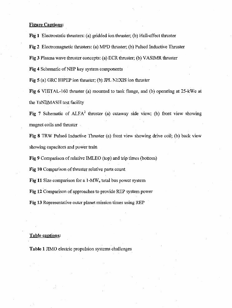
Figure Captions:
Fig 1 Electrostatic thrusters: (a) gridded ion thruster; (b) Hall-effect thruster
Fig 2 Electromagnetic thrusters: (a) MPD thruster; (b) Pulsed Inductive Thruster
Fig 3 Plasma wave thruster concepts: (a) ECR thruster; (b) VASIMR thruster
Fig 4 Schematic of NEP key system components
Fig 5 (a) GRC HIPEP ion thruster; (b) JPL NEXIS ion thruster
Fig 6 VItlTAL-160 thruster (a) mounted to tank flange, and (b) operating at 25-kWe at
the TsNI1MASH test facility
Fig 7 Schematic of ALFA 2 thruster (a) cutaway side view; (b) front view showing
magnet coils and thruster
Fig 8 TRW Pulsed Inductive Thruster (a) front view showing drive coil; (b) back view
showing capacitors and power train
Fig 9 Comparison of relative IMLEO (top) and trip times (bottom)
Fig 10 Comparison of thruster relative parts count
Fig 11 Size comparison for a 1-MWe total bus power system
Fig 12 Comparison of approaches to provide REP system power
Fig 13 Representative outer planet mission times using REP
Table captions:
Table 1 JIMO electric propulsion systems challenges

•
---.......'" ,....... \
\.....- -.,-.,,,,, 1------+-----
r---;:::=1~/.\-':'-~ "... _, /
/ ,. ~__ ....... i. +~ ~
I I +- ..
I I ..I I ..I I· ,..I I • .., I • ....
(a) (b)
Fig. 1. Electrostatic thrusters: (a) gridded ion thruster; (b) Hall-effect thruster

•
(a)
Injection Phase
(b)
Acceleration
Fig. 2. Electromagnetic thrusters: (a) MPD thruster; (b) Pulsed Inductive Thruster

Magnet Coils
~
(a) (b)
•
Fig. 3. Plasma wave thruster concepts: (a) ECR thruster; (b) VASlMR thruster
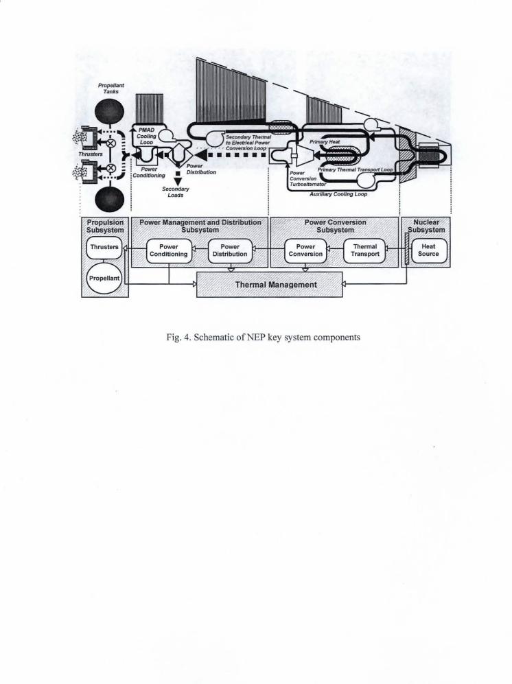
,
_/antTanks
Aux lIary Cooling Loop
Fig. 4. Schematic ofNEP key system components
Nuclear/..:'SUbsystem
HeatSource
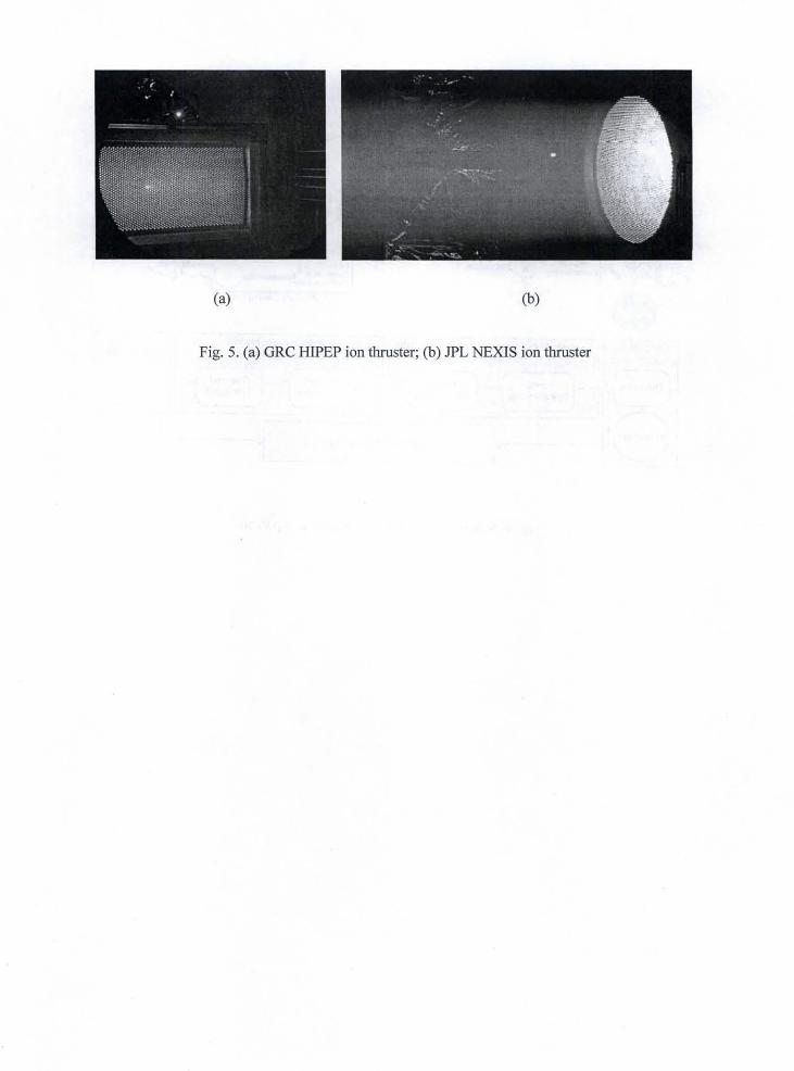
(a) (b)
Fig. 5. (a) GRC HIPEP ion thruster; (b) JPL NEXIS ion thruster

•
•
(a) (b)
Fig. 6. VHITAL-160 thruster (a) mounted to tank flange, and (b) operating at 25-kWe at theTsNIIMASH test facility

•
•
(a) (b)
Fig. 7. Schematic of ALFA' thruster (a) cutaway side view; (b) front view showing magnet coils andthruster

•
•
(a) (b)
Fig. 8. TRW Pulsed Inductive Thruster (a) front view showing drive coil; (b) back view showingcapacitors and power train

25Relative IMLEO*
•--o-- Xe-Ion
NH3-NuPIT
- o - NI-I3-NuPIT- Extra Life
mO-NaPIT (gFRL0-..o-- Li-ALFA2
- o- Li-ALFA2-ExtraLife--o--- Bi-VHITAL
- o- Bi-VH1TAL-EXtraLife
• At Same "ll"ip Tram
as Ion System
_l 2D •
.......... •-_ .... - ..........................................
05 .....
122
#4
0z
0_6
Relative Trip Tnne*--.o-- Xe-Ion
--c--- NH3-NuPIT
- o - NI-/3-NuPIT - Extra Life
H20-NuPIT (ETRU)Li-ALFA2
- o- Li-ALFA2-EXtraLife
-..o-- Bi-VH1TAL
- o- Bi-VH1TAL-ExtraLife
* At Same IMLEO
as Ion System
200 AU Saturn 200 AU 1-Way R.T. R.T.@ 10 Orbiter, @ 5 Mars Lunar Mars
AU/Yr, 7-Years AU/Yt, Cargo, Cargo, Cargo,25-Years 415- 2.2-Years 09-Years 22-Years <-Ion System Trip 'lTttne
Years E->M E->M E->M
Fig. 9. Comparison of relative IMLEO (top) and trip times (bottom)
O_
200 AU Saturn 200 AU 1-Way R.T. R.T.@ I0 Orbiter, @ 5 Mars Lunar
AU/Yr, 7-Years AU/Yr, Cargo, Cargo, Cargo,2S-Years 41.5- 22-Years 09-Years 22-Years
Years E->M E->M E->M
Relative Parts Count*
--o--- Xe-lon
--o-- NH3-NuPIT• o - NH3-NuP1T- Extra Life
H20-NuPIT (ETRU)--o--- Li-ALFA2
- o- Li-ALFA2-ExtraLifo
---o-- Bi-VHITAL
- o- Bi-VH1TAL- Extra Life
* At Same _ Time
as Ion System
<- Ion System Trip Time
Fig. 10. Comparison of thruster relative parts count

i2m
. 2 k eintoNEPPPU
.6.000 s)
Typical Launch VchrlePayload Sbrotxt Diameter (4.5 m)
Fig. 11. Size comparison for a I-MW, total bus power system
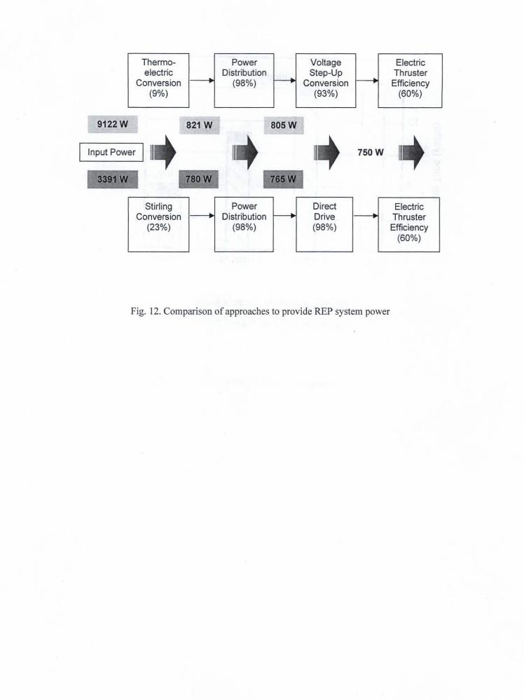
•
..
Thermo- Power Voltage Electricelectric Distribution Step-Up Thruster
Conversion 1-+ (98%) r- Conversion f-----. Efficiency(9%) (93%) (60%)
9122W
Input Power
821 W 805W
750W II
Stirling Power Direct ElectricConversion 1-+ Distribution f-- Drive 1-+ Thruster
(23%) (98%) (98%) Efficiency(60%)
Fig. 12. Comparison of approaches to provide REP system power
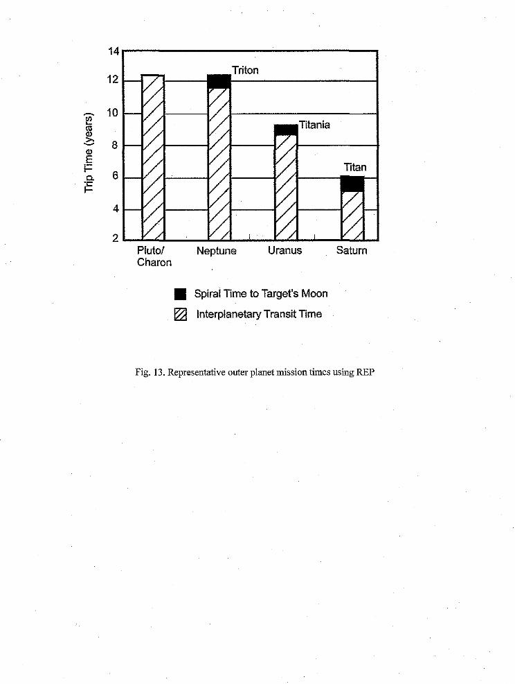
Eo_
t--t_
14
12
10
8
6
4
2
Triton
Pluto/Charon
Neptune Uranus Saturn
• Spiral Time to Target's Moon
[] Interplanetary Transit Time
Fig. 13. Representative outer planet mission times using REP
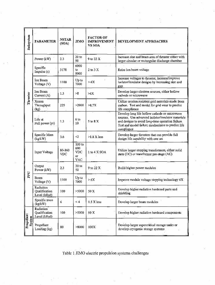
FACTOR OFNSTAR
pARAMETER JIMO IMPROVEMENT(SOA)._ VS SOA
20 toPower (kW) 2.3
50
6000Specific 3170 to
Impulse (s) 9000
Ion Beam 1100 Up toVoltage (V) 7000
Ion Beamk
o Current (A) 1.3 >8
= Xenon
Throughput 229 >2000
(kg)
Life at 6 to1.3
Full power (yr) 10
Specific Mass 3.6 <2(kg/kW)
100 to
60080-160
Input Voltage VDC VDCor
VAC
Output 2.3 20 toPower (kW) 50
Beam 1100 Up toVoltage (V) 7000
Radiation
Qualification 100 >5000
Level (kRad)
Specific mass 6 < 4(kg/kW)
Radiation
Qualification 100 >5000
_ Level (kRad)
_. m Propellant_ Loading (kg) 80 >8000
DEVELOPMENT APPROACHES
9to 22XIncrease size and beam area of thruster either with
larger circular or rectangular discharge chamber
2 to 3 X Raise ion beam voltage
> 6XIncrease voltages to thruster, increase/improve
isolator/insulator designs by increasing size and
gap
>6X Develop larger electron sources, either holinwcathode or microwave
Utilize erosion resistant grid materials made from
>8.7X carbon. Test and model for grid wear to predict
life compliance
5to8X
Develop long life hollow cathode or microwavesources. Use advanced isolator/insulator materials
and designs to avoid long-time opera'don failure.
Test and model failure mechanisms to predict life
compliapce
>1.8 X less Develop larger thrusters that can provide fulldesign life capability with one set
I to 4 X SOA Utilize larger stepping transformers, either solidstate (DC) or transformer pre-stage (AC)
9 to 22 X Build higher power modules
> 6X Improve module voltage stepping technology 6X
50X
1.5 X less
Develop higher radiation hardened parts and
shielding
Develop larger beam modules
50X Develop higher radiation hardened components
IOOXDevelop larger supererifical storage tanks or
develop cryogenic storage systems
Table 1 JIMO electric propulsion systems challenges