for the data-transceiver trx4s - symek packet-radio the data-transceiver trx4s issue: 1999-06-21 ......
TRANSCRIPT

Datensysteme und Elektronik GmbH
User ManualFor the Data-Transceiver
TRX4SIssue: 1999-06-21 (TRX4S-G)
Production and distribution: SYMEK GmbH, Datentechnik, Ulf Kumm, DK9SJAddress: D-70597 Stuttgart (Germany), Johannes-Krämer-Straße 34
Phone: +49-711-76 78 923, Fax: +49-711-76 78 924, Hotline: +49-711-76 54 911 e-mail: info @ symek.com; Internet: http://symek.com

Page 2 TRX4S-G
SYMEK High-Speed Packet-Radio-ControllerThe packet-radio-controller of the TNC3-family (TNC3S, TNC31) are capable to handle up to 1 Mbit/sdata rate. Standard modems for 1200, 9600, 19200, 38400, 76800 and 153600 Baud are available.There exist special modems for mixed baudrates (e.g. TX 9600/RX38400) for satellite applications asUO-12 and others. The TNC3/31 is the optimal controller for use with the TRX4S data transceiver.
TNC3S: Dual port packet-controller (two independent modems), 256 Kbytes Flash-EPROM, max.2 Mbytes CMOS-RAM, max. 1,6 Mbit/s total data rate. Software: Hostmode, Mailbox, KISS, SLIP,Hayes, Sixpack, X-Net.
TNC31S: Single port controller up to 1 Mbit/s. 128 or 512 Kbytes Flash-EPROM, max. 512 KbytesCMOS-RAM. Software same as TNC3S.
TRX4S-G Page 3
ContentsSYMEK HIGH-SPEED PACKET-RADIO-CONTROLLER ............................................................ 2
PREFACE .........................................................................................................5
INSTRUCTIONS FOR USE ...............................................................................6CONTROLS OF TRX4S ..................................................................................................... 6
PROGRAMMING...............................................................................................7CONNECTION OF THE INTERFACE........................................................................................ 7OPERATION WITH THE PROGRAM TRX4TERM.EXE ............................................................... 7OPERATION USING A TERMINAL PROGRAM ............................................................................ 7PROGRAMMING THE CHANNELS .......................................................................................... 8SELECTING THE CHANNELS (UP/DOWN KEYS) ........................................................................ 8
CONNECTORS ...............................................................................................10CONNECTOR FOR MODEM OR TNC ....................................................................................10
Cable between TRX4S and TNC.............................................................................................................................10Signals from and to the modem..............................................................................................................................11
REMOTE-CONTROL CONNECTOR'.......................................................................................12POWER SUPPLY, FUSES ...................................................................................................12OPERATING HINTS...........................................................................................................13
TX-Delay setting......................................................................................................................................................13
TECHNICAL DESCRIPTION ...........................................................................14TECHNICAL DATA OF TRX4S (VALID FOR 1999 VERSION C OF PRINTED CIRCUIT BOARD) ...........14INTERFACE CABLE FOR SERIAL RS232 INTERFACE ................................................................15TERMINAL-PROGRAMS (SET-UP) ........................................................................................16
Configuration of TERM 10.36 (ms-dos program by DL5FBD) ...........................................................................16Configuration of 'Terminal' (Windows 3.11).........................................................................................................17Configuration of Hyperterm (Windows95/98) ......................................................................................................17
COMMANDS OF THE TRX4S FIRMWARE 1.1 ........................................................................18Storing a record ......................................................................................................................................................18Reading a record.....................................................................................................................................................18Reading all 16 records............................................................................................................................................18Selecting the current channel .................................................................................................................................19Reading the current channel-number ....................................................................................................................19Reading the s-meter (signal strength)....................................................................................................................19Temperature display (output power)......................................................................................................................19Display firmware-version number .........................................................................................................................20Show serial number.................................................................................................................................................20Error messages of TRX4S, syntax ..........................................................................................................................20
SERVICE-ADJUSTMENTS .............................................................................21PROGRAMMING OF EEPROM-MEMORY..............................................................................21
POKE: write byte to EEPROM ..............................................................................................................................21PEEK: read byte in EEPROM................................................................................................................................21EEPROM memory map...........................................................................................................................................21
INTERNAL ADJUSTMENTS ...........................................................................22OPENING THE CASE .........................................................................................................22TOTAL DISASSEMBLING THE TRX4S ..................................................................................22ADJUSTMENT OF THE TRANSMIT POWER..............................................................................23

Page 4 TRX4S-G
Adjustment transmit power:....................................................................................................................................24ADJUSTING OF TEMPERATURE LIMITATION ...........................................................................25
Setting the temperature limit: .................................................................................................................................25ADJUSTING OF RF CARRIER DETECTION...............................................................................25ADJUSTMENT OF THE MODULATION (DEVIATION) ..................................................................26ADJUSTMENT OF THE MODULATION (COMPENSATION)............................................................26ADJUSTMENT OF THE REFERENCE QUARTZ ..........................................................................27ADJUSTMENT OF THE LOCAL 60,3 MHZ OSCILLATOR ............................................................28ADJUSTMENT OF TX-VCO...............................................................................................28ADJUSTMENT OF RX-VCO...............................................................................................28ADJUSTMENT OF QUADRATURE COIL...................................................................................28IF-FILTER ADJUST ...........................................................................................................28ADJUSTMENT OF 90,45 MHZ STAGES ................................................................................29ADJUSTMENT OF TRANSMITTER DRIVER 435 MHZ ................................................................29ADJUSTMENT OF FINAL AMPLIFIER AND LOWPASS FILTER........................................................30UPDATE OF FIRMWARE.....................................................................................................30DISABLING THE 7-SEGMENT DISPLAY ..................................................................................30SWITCHING TEMPERATURE / POWER READING......................................................................30MEASURING POINTS ........................................................................................................31REMOTE-CONTROL CONNECTOR .......................................................................................32
Ground, + 5 volt, clock for power supply of a remote control unit .....................................................................32Push button functions 'up' and 'down' for channel selection ...............................................................................323-wire interface for output of 7-segment-display, power-setting, mode..............................................................32serial asynchronous 9600 baud interface for programming etc. .........................................................................33
DETAILED CIRCUIT DESCRIPTION...............................................................33
REGULATIONS, ETC.....................................................................................36
SCHEMATICS, PART LOCATION ..................................................................37LOCATION OF THE PARTS (LEFT HALF) ................................................................................37LOCATION OF THE PARTS (RIGHT HALF)...............................................................................38SCHEMATICS TRX4S (AF, TX, POWER-SUPPLY).................................................................39SCHEMATICS (RECEIVER, CONTROL) ..................................................................................40
WHAT TO DO IF THE TRX4S DOES NOT WORK? ........................................41
INDEX .............................................................................................................42
CONVERSION VOLT, WATT, DBM.................................................................46

TRX4S-G Page 5
PREFACEPacket-Radio is usual with amateur radio since 1982. Starting with 1200 Baud data rate on 2m band,the standard today (1999) is 9600-Baud FSK (G3RUH).
With 1200 Baud AFSK, every radio could be connected by use of the microphone and speaker con-nector. For 9600 Baud FSK, most radios need to be modified. Modern fm transceivers offer a '9600Baud capability'.
As those FM-transceivers had been designed for fm-speech operation, they are not ideally suited forpacket-radio. Neither the receivers nor the transmitters are really optimised for data transmission andthe delay between transmit and receive is far too long.
For a real data transceiver, the following facts need to be observed:
• Base band transmission and reception with a AF frequency range from 20 to 5000 Hz (9600Baud) and 150 Hz to 80 kHz (153 kbaud) without distortion of amplitude or phase.
• The transmit-receive delay time must not take longer time as the transmission of approx. 50 bit ofdata. This is equivalent to 5 ms (9600 Baud) or 250 µs (153 kbaud).
• The if-bandwidth should be as wide as 30 kHz (for 19200 Baud) and 300 kHz (for 153 kbaud).The filters should be of the group-delay-optimised type..
• Simplex-operation (transmit and receive at the same frequency) must be possible without restric-tions.
As these requirements are not met by any commercial available transceiver, SYMEK developed aspecial radio for high speed data transmission in the 435 MHz band. The TRX4S is not only a modi-fied fm-speech-transceiver, but all parts had been developed new.
The development was mainly done by Gunter Kühnhardt, DC4SU (rf), Günter König, DG4SAS (mi-crocontroller) and Ulf Kumm, DK9SJ (management, PCB-layout) in 1998 and 1999.
We succeeded in constructing a real data transceiver without restrictions in speed, power and delay.
We hope, you enjoy using the TRX4S.
The firmware of TRX4S may be updated or other versions may be available in future. You may orderupdates, which come together with a new manual. See our internet pages for announcement of newfirmware releases.
This is the first English version of the TRX4S users manual. If you find any errors in the text, pleaseinform us. We'd like to correct them immediately to give our customers the best documentation to ourproducts possible. 21-Jun-1999 Ulf Kumm, DK9SJ
IMPORTANT: All information in this manual are valid only for the version TRX4S-C of the TRX4Sprinted circuit board and the firmware release 1.1.

Page 6 TRX4S-G
INSTRUCTIONS FOR USE
Controls of TRX4SIf you have some experience with packet-radio, this side will give you all information required foroperating TRX4S transceiver.
The TRX4S is operated with the cooler up.
LED-Displays, Front-panel Controls (from left to right)
REMOTE connector for a remote control panel (see 'remote-control')AUDIO: volume (only effective for the AF amplifier / speaker connector)SQUELCH: squelch (only effective for the AF amplifier / speaker connector)NARROW: the transceiver runs in narrow mode (up to 19200 Baud)RSSI DCD: a rf signal is detectedRX: the transceiver is in receive modeTX: the transceiver is on air (transmitting)PWR: power, the power supply of TRX4S is turned on (internal 5 volt)
Connectors (back panel) (from left to right)
ANT: antenna, BNC-connector, 50 Ω, max. 30 Watt rfPower supply 12 (13,8) Volt, max. ca. 6,5 A. red = positive, black = negative.SPKR speaker connector 8 Ω, 3,5 mm mono-jack, max. 0,5 WModem/TNC data-connector for TNC, 6-pin mini-DIN-plug (see 'data connector')RS232 interface to the computer, 9600 Baud, 8 Bit, NO Parity (see 'programming')
Channel Selection (local)
For selecting the frequency-channel you have to turn the TRX4S round (Cooler down).
On the right side between the RS232-connector (rear) and the remote-control connector you find a7-segment LED-display and two 3 mm holes. With a appropriate pin, pushed through these holes,you can press two buttons inside of the TRX4S. to switch the channel number up and down. With anadditional remote control unit, the same functions (up, down, display) are possible.
Set-up
In any case, you will have to program the desired frequencies into TRX4S EEPROM. Please see thechapter 'programming' and set all frequencies as needed. As default, channel No. 0 (TX = RX =433,000 MHz, narrow, 3 Watt) is programmed.
TRX4S-G Page 7
PROGRAMMING
Connection of the InterfaceUse the interface cable supplied with the TRX4S and plug it to the 9 pin connector at the serial COM-interface of your computer.. (COM1 or COM2). If your computer has a 25 pin male connector insteadof a 9 pin, you may use a standard adapter (25 pin female to 9 pin male) .
The rs232-interface and connector of TRX4S is compatible to the TNC31 connector. The baudrate isfixed to 9600 baud.
If you like to make your own interface cable, please read the detailed description on page 15.
Operation with the program TRX4TERM.exeOn the disc, you find the program 'TRX4TERM.exe'. By use of this program you can do all settingsof the transceivers. The program is started from dos or window and is fully self-explaining. Prerequi-site for using TRX4TERM is the proper connection of the TRX4S to one of the serial ports COM1 orCOM2 of the computer. The program will check if a TRX4S with the proper firmware is connected toone of the two COM-ports. Connection of two TRX4S at COM1 and COM2 at the same time is possi-ble. The hardware-handshake of the COM interfaces have to be fully wired, it is not sufficient toconnect only TxD, RxD and ground. (see page 15). Important: do not start TRX4TERM if one of thecom-ports is busy with another (terminal-) program.
With TRX4TERM, you can do the following settings:
• check and set the current channel number.• read and set all frequencies, power and mode• read the s-meter and display it as bar graph• read the temperature (or output power) and display it as bar graph• read the firmware-version number and serial number of the transceiver• read, store and write the EEPROM contents• calibration of temperature, signal strength and power reading
Do not switch off the transceiver when the TRX4TERM program is running.
Operation using a terminal programFor all settings of TRX4S, you may use a standard terminal program instead of TRX4TERM as well.
The serial (rs232) interface (COM-port) of your PC has to configured as follows:
baudrate: 9600parity: N (none)bits/character 8Xon/Xoff, protocol: offRTX/CTS handshake: offstop bits: 1
How to set these parameters depends on the program used. On the supplied disc, you find a simpleprogram 'TERM', which can be used for TRX4S without further configuration. For Atari you can usethe VT52-emulator on the accessory disc..

Page 8 TRX4S-G
Connect the TRX4S to the serial (com) port of your computer and run TERM (simply directly from thedisc). TERM is ready configured to use COM1 as serial port. To use it with COM2, press ALT-P, E,2, <return>, <escape>. This setting can be stored by pressing R before <return>. Otherwise, TERMwill use COM1 when started again.
Now switch power of TRX4S on. The transceiver will prompt:
K0=0433.0000 N 1 0433.0000
If this or a similar line is displayed, the interface works perfectly. Type:
VERS
The transceiver replies with the version number of the firmware, e.g.
SYMEK TRX4S CPU4 V1.1
The communication between terminal and transceiver is now completely checked.
Programming the channelsThe TRX4S can store 16 channels. With the up and down keys at the transceiver you may select thechannels. The led-display shows the channel number in hexadecimal, i.e. the figures appear in thesequence
0 1 2 3 4 5 6 7 8 9 A B C D E F 0 1...
Future versions of TRX4S may be reduced to 10 channels.
With a PC and a terminal program (called 'terminal') you can now set the channels. . We recommendthe program TERM (dos), Terminal.exe (Windows 3.11), Hyperterm (Windows95 and Windows98) orany other terminal program (Telix etc.). Of course, you can use other computers (Atari, Amiga, Appleetc.) as well.
The setting uses short records, containing exactly 26 characters e.g.
Z0=0433.2500 N 2 0433.5125
This record contains the following information: :
Z0= command: the line will be stored in EEPROM as channel 0 setting.0433,2500 transmit frequency in MHzN mode of operation for transmitter and receiver: N = narrow, W = wide2 programmed transmit power level 2 (6 Watt)0433.5125 receive frequency in MHz
Program now all settings for the channels 0 to F.
If this programming shall be made automatically (by a software program), there has to be a guardtime of 250 ms after each line. after the next record may be sent. The TRX4S will need this wait timefor storing the received information into EEPROM.
Selecting the channels (up/down keys)With the up and down keys, you can select one of the 16 stored channels as the current channel. .The current channel will be shown oh the 7-segment display. The number of the current channel isstored immediately.
At power-on of the transceivers, the current channel at last power-off is set automatically. . So, it ismade sure that no settings are changed when cycling power.
TRX4S-G Page 9
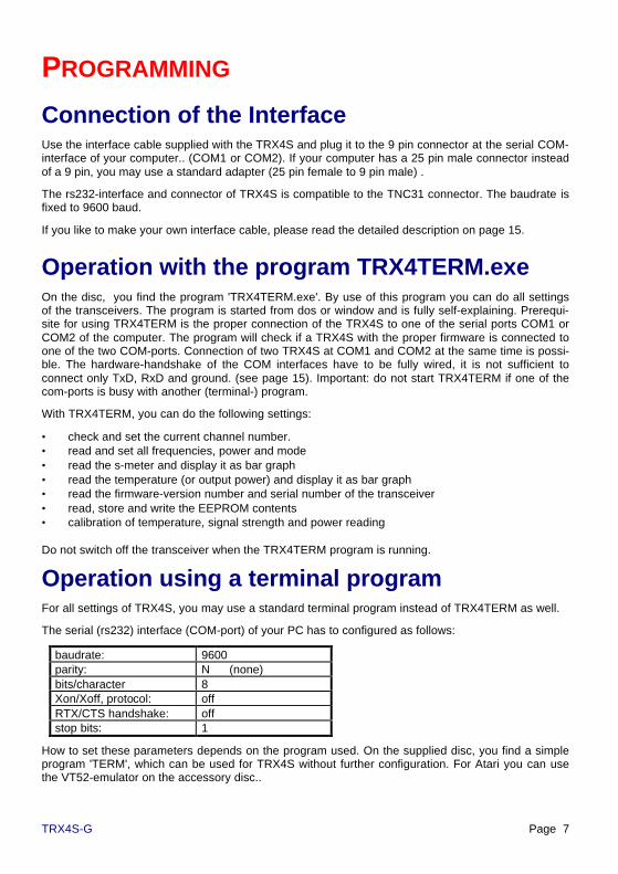
When pressing the 'up'-key‘, the channel number is incremented by 1. After 'F', the number changesto '0' again. So, the use of the 'down'-key is not imperative.
The 'up' and 'down' keys may be accessed through the 3.1 mm holes near the led-display in thealuminium bottom panel of TRX4S. Use a 3 mm pin or screw to press the key inside the transceiver.If the display is on top and located to the right hand (connectors rear, controls front), the upper key isthe 'up' and the lower (towards front side) is the 'down' key. It is sufficient to access only one of thetwo keys: pressing 15 times 'up' has the same effect as pressing 'down' once.
Page 10 TRX4S-G
CONNECTORS
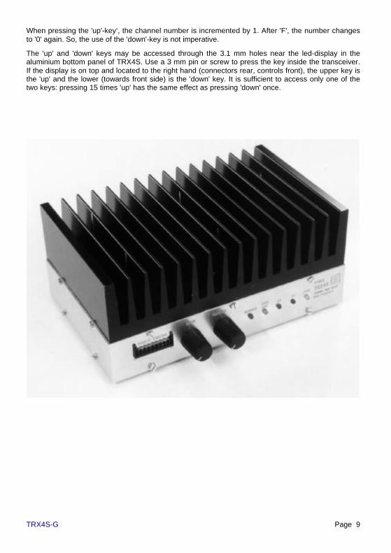
Connector for modem or TNCOn the rear side of TRX4S you find a 6-pin mini-DIN-connector. for connection of a packet-radio-controllers (TNC) or other modems. The pins are assigned as follows:
Pin 1: modulator, output of TNC
Pin 2: ground
Pin 3: PTT
Pin 4: data, input of TNC
Pin 5: +10 volt (current limited)
Pin 6: RSSI-DCD output
Cable between TRX4S and TNC
The wiring of all 5-pin DIN connectors of SYMEK TNC is the same:
Pin 1: modulator, output of TNC
Pin 2: ground
Pin 3: PTT
Pin 4: data, input of TNC
Pin 5: not connected
The cable between TNC and TRX4S has to be as follows: :
TRX4S6-pin mini-DIN
Signal TNC5-pin DIN
Pin 1 modulation Pin 1Pin 2 ground Pin 2Pin 3 PTT Pin 3Pin 4 demodulator Pin 4Pin 5 RSSI-DCD N.C.Pin 6 +10 V N.C.
6-pin Mini-DIN connector,
outside view to the case
5-pin DIN-connector at TNC

TRX4S-G Page 11
Signals from and to the modem
Description of the inputs and outputs of the data connector of TRX4S. All signals refer to ground (Pin2).
Modulation-input (Data in) Pin 1
Here, the data output of the modem is connected. The radio is adjusted, that the proper modulationdeviation is reached at 0.5 volt (peak to peak) modulating voltage. (equals 180 mVeff (effective). Thisis valid for 9600/19200 baud narrow as well as for 76/153 kbaud wide band mode. The deviation canbe adjusted with trimmers inside the TRX4S, but we recommend to adjust the proper output level atthe modem.
The input impedance of TRX4S is 22 kΩ. If you have capacitors in series with this input, make surethey have a capacity of 22 µF or more. Otherwise, the low frequencies are not properly modulated.
The input is free from dc, so an additional coupling capacitor is not necessary and even disadvanta-geous. The dc voltage across the modulation input may vary from –5 to +5 volt. If higher voltagesare present, connect a additional capacitor in series.
The frequency range of the modulating signal reaches from 5 to 10000 Hz (narrow mode) and from50 Hz to 90 kHz (wideband mode). The spectrum outside this range is suppressed by the modulationamplifier. The lowpass filters are switched automatically according to the wide/narrow selection.
Receiver output (Data out) Pin 4
The TRX4S uses two different if amplifiers and demodulators for narrow and wideband operation.According to the setting, one of these two outputs is switched to pin 4 (data out) of the modem con-nector.
The demodulator-outputs are buffered by a lowpass amplifier and have a very low output impedance.The output resistance is 220Ω in series with a 22 µF capacitor. With an external load of 1 kΩ thisresults in a low corner frequency of approximately 10 Hz. Do not connect a modem with lower im-pedance or add capacitors in series. Otherwise the output bandwidth would be reduced.
The output is dc-free and decoupled by a capacitor. A external dc voltage of –5 to +5 volt may beapplied.
The frequency range of the output signal goes from few Hz up to 30 kHz (narrow) or from 50 Hz to100 kHz (wide band mode). (with high impedance load)
The output voltage depends on the deviation of the received signals and is approximately 0,5 voltpp
(peak to peak) (180 mVeff (RMS) and cannot be changed / adjusted.
Transmitter keying (PTT) Pin 3
The PTT-pin shows + 5 Volt when receiving (open circuit). If it is pulled to ground (by the modem orby a switch), the transceiver starts transmitting immediately.
To keep the time from PTT-line going low to transmitting short, this input should be pulled directly toground without series resistors. . The transmitter is keyed as soon as the voltage at pin 3 goes below2 volt. The pull-up-resistor to 5 volt has a value of 47 kΩ. A low pass against radio-frequency inter-ference with 200 kHz corner frequency is built-in.
Carrier signal detection output (RSSI-DCD) Pin 6
As soon as the rf input signal at the antenna input of TRX4S exceeds an adjustable level, the greenDCD led at the front of TRX4S lights. Simultaneously, pin 6 of the modem connector is pulled toground (low).
The rf signal level, at which the RSSI-DCD reacts, may be adjusted by two separate trimmers fornarrow and wide mode inside the TRX4S. The trimmer are pre-adjusted for detection of signals
Page 12 TRX4S-G
exceeding 0,5 µV antenna input voltage in narrow and wideband mode. Note: If much noise is pres-ent at the receiver input (QRM, QRN or by additional noise of a preamplifier), the trigger level ofRSSI-DCD has to be adjusted to higher levels.
The output is an open collector output, capable to switch up to 16 mA to ground. The maximal per-missible voltage is 30 Volt. Caution: this output is not protected against overload.
10 volt external supply (+10V) Pin 5
For supply of external low power circuitry, the internal 10 volt supply is present at pin 6 of the 6 pinmini-DIN connector. To avoid damage by overload or short circuit, a resistor of 600 Ω is in series withthe output. So, the current drawn is limited to few mA. A microphone amplifier or similar circuitry maybe supplied from this output without problems.
Avoid permanent short circuit of the output. The short circuit current is 10v / 600Ω = 16 mA.
Remote-Control connector'Here, you may connect a remote control circuitry. The following control functions are accessible viathis connector:
• power supply (ground, +5 volt)• serial interface (5-Volt RS232) for remote control• up and down keys• 3-wire interface for 7-segment-display and mode display (power, narrow/wide)• 12,800 000 MHz ttl output of the reference oscillator
Power supply, fusesThe power is applied via the 2 wire cable, supplied with the TRX4S. The 2 pin connector is a stan-dard AMP universal mate-n-lok no. 350777 type, the 2 pin plug for the cable is used with two femalecrimp contacts AMP Mate-N-Lok No. Type 163306-4. The connector is good for up to 25 amp andcannot be reversed in polarity.
The 12v dc power must not be reversed in polarity. If the power is applied with the wrong polarity, afuse inside the TRX4S will blow and has to be replaced.
For replacement, use only a 6,3 A fuse (20 x 5 mm) with medium fast characteristic. Never shortcircuit the fuse by a wire. Never use higher current types. The fuse is found directly near the powerinlet and can be easily accessed by opening the TRX4S bottom cover. Take care not to damage thespeaker wires when opening the case.
To make sure that there is no voltage drop on the supply cable, you have to use wires with sufficientdiameter. With only 0,1 Ω total resistance of the supply cable, there would be already a significantvoltage drop of 0,5 volt, but the maximum output power is only possible with 13,0 volt supply acrossthe power input of the TRX4S.
Inside the TRX4S, there is a low-ESR electrolytic capacitor with 180 µF, which cannot work asmoothing capacitor for low quality power supplies. . The power source has to supply 13.5 Volt withpermanent 6 A and 8 A peak current. The low-cost CB-radio power supplies with so-called '6/8 Apower capability' will quickly overheat, when the transmit/receive ratio exceeds 20%. In many cases,the open circuit voltage of those power adapters exceeds 15 v. The ac filtering / smoothing of theoutput voltage is not perfect, which causes in 100 Hz amplitude modulation of the fm carrier. Thepower supplies designed for amateur radio transceivers (13,5V 12A) have much more power reserveand are well suited for use with TRX4S even when transmitting for longer time. Of course, you mayuse a car battery for supplying the TRX4S. Take care to use wires with adequate cross-section. .

TRX4S-G Page 13
Operating hintsTX-Delay setting
The real TX-delay of TRX4S is 1 ms or less. Watch the following points when setting the parameter'T' at your TNC:
• TNC: the extremely short delay-time cannot be programmed with most of the packet-radio-controllers available today (1999). With TNC2H or other TNC2 (Z80) derived TNC, the TX-delaycan be programmed in multiples of 10 ms only. T 0 is always too short, T 1 means already 10ms delay and is much too long. The TNC3 allows programming the TX-delay in 1 ms steps. Inaddition, a TX-delay of 0 can be set and a preamble of up to 16 flags may replace the T settingand gives a delay, which is proportional to the baudrate. (TNC3-Firmware 1.8 and later).
• partner station: when setting the transmit-delay you have to observe, that this time is not onlyrequired for your own transmitter to start operating but also for the receiver of the station, youare in contact with for switching off its the transmitter completely, switching on its receiver up tofull sensitivity and getting its receiving modem synchronised. If you work with a simplexdigipeater which needs 50 ms to switch from transmit to receive, you have to consider this. Ifnot, the remote receiver will loose the fast answers from your TNC and has to wait for a re-peated transmission. The remote station will show all your packets in monitor mode except thefirst one, which came too early.
• The transmit filter of a G3RUH-modems needs some bit preamble until valid data is sent. Thereceiver of those modems needs some clock cycles as well to synchronise and lock the clockrecovery circuit. Those delays depend on the baudrate and become shorter as baudrate rise.
Recommendation: With TNC2H and TNC3/TNC31 the minimum TX-delay of T 1 can be set. If thereis a problem, check if the slow receiver of the remote station is the cause and increase TX-delay untilthe problem disappears.

Page 14 TRX4S-G
TECHNICAL DESCRIPTION
Technical data of TRX4S (valid for 1999 version C of printed circuit
board)
Dimensions: without case, without cooler: W= 163 mm, D= 103 mm, H= 29 mm, weight 0,5 kg.Without case, with cooler: W=163 mm, D=103 mm, H=70 mm, weight 1,5 kg
Power supply: 12 volt dc (11...16 V) reception: 250 mA; transmit max. 6 A,2-pin AMP receptacle. Fuse 6,3A slow inside the case (fuse 20x5 mm). 13 v required forfull transmit power of 25 watts. Typical values at 12,5 v :RX: 0,27A; TX 3 W: 2,2 A; TX 6 W: 2,6 A, TX 12 W: 3,5 A; TX 20 W: 5,0 A.
Frequency range: Standard adjustment: 430 - 440 MHz
Frequency drift / error: typ. ± 2 PPM (= ± 1 kHz), max. ± 5 PPM (= ± 2,5 kHz),
Channel spacing: 12,5 kHz
Temperature range: 0 to 50 C.
Programming: via rs232-serial interface (9600 Baud, 8 Bit, NO Parity), 8-pin RJ45 receptacle. Forevery channel, the transmit frequency, receive frequency, transmit power and mode maybe defined and stored. Reading of signal strength in dBm and temperature is possible.Connection of a remote control unit is possible.
Frequency setting: any 16 frequencies may be programmed and stored in TRX4S. Selection withup-down buttons inside the transceiver. 7-segment channel display.
Over-temperature protect: transmitter will be disabled above 60 to 65 C temperature of the poweramplifier.
Reference oscillator: 12,800 MHz ± 5 PPM
Antenna switch: 3 power pin diodes.
Useful packet data rate: max. approx. 50 packets (256 Bytes each) or 100 packets (100 Byteseach) per second.
Receiver:Sensitivity: 0,2 µV at 50 Ω (12 dB SINAD, narrow-mode)Maximum input signal: without destroying the input:in band (430-440 MHz): +13 dBm = 20 mW = 1 v rf voltage< 400 MHz, > 470 MHz: +33 dBm = 2 Watt = 10 Volt rf voltageAudio amplifier: 0,5 W at 8 Ω, 3,5 mm speaker jack,built in miniature speaker. The speaker is not disabled when transmitting.So, the transmitted signal can be heard (simplex mode)Data-output: 0,5 voltpp, low impedance, 6-pin mini-DIN-connectorMirror frequency suppression: 506 MHz and 364 MHz: >70 dBSignal detection (rf-DCD): two (narrow/wide) separately adjustabletriggers show if a rf signal is present. RX-on-delay: Delay from 'PTT = high' until reception:< 2 µsWideband mode:
selectivity: ± 300 kHz: >60 dB, stop band: >110 dBAF-bandwidth: 50 Hz to 80 kHzdynamic range: -120 dBm = 0,2 µV to –40 dBm = 2 mV
Narrow mode:

TRX4S-G Page 15
selectivity: ± 35 kHz: >90 dB, stop band: >110 dBAF-bandwidth: 10 Hz to 10 kHzdynamic range: -125 dBm = 0,1 µV to –50 dBm = 1 mV
Transmitter:Output power: programmable 3/6/12/25 watt at 50Ω(with supply voltage below 13 v only 20 watt)Efficiency: typ. 5,5 A / 13 V = 75 watt input at 25 w output. η= 35 %Duty cycle: depending on ambient temperature and cooling conditions,a average transmitter power of 12 watt (25 Watt at 50% duty cycle) is allowed. Permanent(100%) transmission at full power requires forced air cooling. (fan) )Power regulation: the output power is kept constant to ±0,2 dB within the total frequencyrangeMod-input: 0,5 Voltpp at 22 kΩ, separate low pass amplifiers for wide and narrow modeWideband mode: audio bandwidth: 30 Hz to 80 kHz, TX-delay (PTT low to full outputpower – 1 dB): 50 µsNarrow mode: audio bandwidth: 5 Hz to 15 kHz, TX-delay: 100 µsCarrier suppression at the transmit frequency when in receive mode: infinite, no spurioussignal present.Harmonic and spurious signal suppression: below -70 dB(c)Transient emissions: at keying with 10 Hz: (50 ms TX, 50 ms RX): <- 40 dB (adjacentchannel), <-50 dB (500 kHz from carrier), <-60 dB (2 MHz distance), referred to carrier andchannel bandwidth (wide).
Interface cable for serial rs232 interfaceThe serial cable to the computer suppliedwith TRX4S. . You plug it into the 9 pin maleconnector of the PC. The cables and con-nections are the same as used withTNC31S.
For serial (rs232) interfaces, modern com-puters uses the small 8 pin rj45 connectorsinstead of the bulky 25 pin sub-d types.Cables and adapters are available in mostcomputer-hardware shops everywhere.Here some explanation to this new tech-nique:
rj45 pin 3 = transmit data from TRX4S tocomputer, output of the TRX4Srj45 pin 6 = transmit data from the computer to TRX4S, input ofTRX4Srj45 pins 4+5 = common ground
As the rj45 connector is not soldered to a cable but fixed by using aspecial tool, the cable cannot be made by hand. But there are inex-pensive ready made cables available in every computer shop. Theyare called 'ISDN-cable' available screened or without screening.(ISDN S0 bus cable for German ISDN standard wall outlets.). Forexpansion of the cable length, there are small adapters availablewith a female contact at each end. Sometimes, the cables have only4 or 6 of the 8 pins wired. This is no disadvantage, as the TRX4Suses only the centre 4 pins no. 345 and 6. The outer pins 1,2,7 and8 are not connected.
TRX4S
RJ-Connector, rear view.Only pins 3,4,5 and 6 areused

Page 16 TRX4S-G
The cables are available as: 8-wire flat cable / modular-cable with rj45 connector, ISDN-cable rj45,patch cable 1:1 connected, cable with 8 pin western-connectors. If you find similar cables withsmaller 6 or 4 pin connectors, as used with other telephone applications, you may use them as well.Screened cables are much more expensive, but provide better suppression of radio interference.
The both connectors are mounted in a way, that the latches of the connectors are on the oppositesides of the (flat) cable. So, the sequence of the pins remain unchanged (see picture).
Caution: There exists cables with so-called 'roll-over-connection'. With those cables, pin 1 is con-nected with pin 8, pin 2 with Pin 7 etc. Since introduction of ISDN, those roll-over cables are unusual.
With the PC serial interface COM1 there is in most cases a 9 pin male connector found at the rear ofthe computer. For COM2, you will find also a 9 pin or in many cases a 25 pin male connector. Whenusing COM1 to connect your mouse, you will use perhaps COM2 for the TRX4S. To connect themodular cable with the rj45, you need the adapter supplied with the transceiver. Here the list whichdescribes how to built such an adapter. (RJ-connector as shown in the picture, view the adapter fromthe rear side.):
1) rj45 pin 3 (black wire) goes to sub-d 9 pin 2 (or sub-d 25 pin 3) Signal: RxD from TRX4S to PC.2) rj45 pin 4 (red wire) goes to sub-d 9 pin 5 (or sub-d 25 pin 7) Signal: ground3) rj45 pin 6 (yellow wire) goes to sub-d 9 pin 3 (or sub-d 25 pin 2) Signal: TxD from PC to TRX4S.4) cut the remaining wires directly at the rj45 connector (pins 1= blue, 2= orange, 5= green, 7= brownand 8= white/grey. You will need them for wiring the hardware handshake lines of sub-d connector.5) click all 8 wires into the sub-d connector body. Caution: as soon as you hear the 'click', the jackcannot be removed again.5a) For 9 pin female sub-d, you put green in pin 1, black in 2, yellow in 3, grey/white in 4, red in 5,brown in 6, blue in 7 and orange in 8. 9 remains empty.5b) For 25 pin female sub-d, you put yellow in 2, black in 3, orange in 4, blue in 5, brown in 6, red in7, green in 8 and white/grey in 20. All others remain empty.6) short circuit the hardware handshake by removing the insulation of the 5 open ended wires andsolder the blue and orange wires together.7) solder the brown, green and grey/white wires together.8) use heat shrink tube to insulate the bare wire joints and complete the adapter by closing the case.Make sure, the rj45 block is completely latched in the adapter case.
Terminal-programs (set-up)The serial interface (COM) of PC has to be set up as follows:
baudrate: 9600parity: N (none)bits/character: 8Xon/Xoff, protocol: offRTS/CTS handshake: offstop bits: 1
How to set these parameters depends on your terminal program. In most cases, the setting is storedin a configuration file and restored automatically when starting the program.
Configuration of TERM 10.36 (ms-dos program by DL5FBD)
On the disc, which is supplied with TRX4S, you find a simple terminal program TERM.exe, and thecorresponding configuration file TERM.cfg. You may run the program directly from the disc. It uses(with the term.cfg) the following settings:
TRX4S-G Page 17
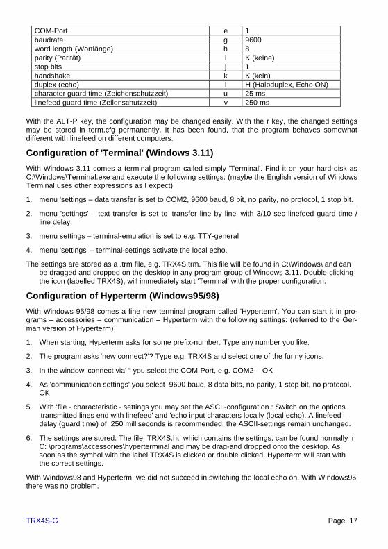
COM-Port e 1baudrate g 9600word length (Wortlänge) h 8parity (Parität) i K (keine)stop bits j 1handshake k K (kein)duplex (echo) l H (Halbduplex, Echo ON)character guard time (Zeichenschutzzeit) u 25 mslinefeed guard time (Zeilenschutzzeit) v 250 ms
With the ALT-P key, the configuration may be changed easily. With the r key, the changed settingsmay be stored in term.cfg permanently. It has been found, that the program behaves somewhatdifferent with linefeed on different computers.
Configuration of 'Terminal' (Windows 3.11)
With Windows 3.11 comes a terminal program called simply 'Terminal'. Find it on your hard-disk asC:\Windows\Terminal.exe and execute the following settings: (maybe the English version of WindowsTerminal uses other expressions as I expect)
1. menu 'settings – data transfer is set to COM2, 9600 baud, 8 bit, no parity, no protocol, 1 stop bit.
2. menu 'settings' – text transfer is set to 'transfer line by line' with 3/10 sec linefeed guard time /line delay.
3. menu settings – terminal-emulation is set to e.g. TTY-general
4. menu 'settings' – terminal-settings activate the local echo.
The settings are stored as a .trm file, e.g. TRX4S.trm. This file will be found in C:\Windows\ and canbe dragged and dropped on the desktop in any program group of Windows 3.11. Double-clickingthe icon (labelled TRX4S), will immediately start 'Terminal' with the proper configuration.
Configuration of Hyperterm (Windows95/98)
With Windows 95/98 comes a fine new terminal program called 'Hyperterm'. You can start it in pro-grams – accessories – communication – Hyperterm with the following settings: (referred to the Ger-man version of Hyperterm)
1. When starting, Hyperterm asks for some prefix-number. Type any number you like.
2. The program asks 'new connect?'? Type e.g. TRX4S and select one of the funny icons.
3. In the window 'connect via' “ you select the COM-Port, e.g. COM2 - OK
4. As 'communication settings' you select 9600 baud, 8 data bits, no parity, 1 stop bit, no protocol.OK
5. With 'file - characteristic - settings you may set the ASCII-configuration : Switch on the options'transmitted lines end with linefeed' and 'echo input characters locally (local echo). A linefeeddelay (guard time) of 250 milliseconds is recommended, the ASCII-settings remain unchanged.
6. The settings are stored. The file TRX4S.ht, which contains the settings, can be found normally inC: \programs\accessories\hyperterminal and may be drag-and dropped onto the desktop. Assoon as the symbol with the label TRX4S is clicked or double clicked, Hyperterm will start withthe correct settings.
With Windows98 and Hyperterm, we did not succeed in switching the local echo on. With Windows95there was no problem.

Page 18 TRX4S-G
Commands of the TRX4S firmware 1.1The TRX4S contains a microcontroller, which communicates with the PC by a serial rs232 interface.The commands, which are understood by the microcontroller are explained here. Every line has toend with a return-character ($13). The number and position of the characters within a commandstring has to match exactly as described here.
Designations:
n channel identifier 0, 1, 2, 3, ... 8, 9, A, B, C, D, E, F
T, R decimal figure for transmit (T) and receive (R) -frequency 0, 1, 2, 3, ... 8, 9
F operating mode: N = narrow, all others = wide N, W
P transmit output power: 4=25 watt, 3=12 watt, 2=6 watt, other: 3 watt, 1,2,3,4the remaining characters (Z, K, S, R, V and the decimal point) must be used exactly as indicated.
Storing a record
With this command, a channel data record is stored in EEPROM of TRX4S. After the command hasbeen executed, the record is read out immediately and returned as acknowledgement to the PC.
input: Zn=TTTT.TTTT F P RRRR.RRRRreply: Zn=TTTT.TTTT F P RRRR.RRRR
Note: the records are not checked for proper syntax. Wrong and nonsense characters after the '=' arestored as given. This may cause unwanted and unexpected settings of the transceiver when select-ing the channel later. In most cases, the wrong frequency setting causes the PLL oscillator not tolock. If the 'transmit'-led remains off when keying the transceiver, in most cases a wrong programmedchannel record is the cause. The same is true for the receiver ('receive'-led doesn't light).
Note: The Z-command changes the contents of the frequency memory, but does not change thecurrent frequency and mode of the transceiver.The new frequency becomes not valid until the chan-nel n (via remote command or by pressing up/down keys or at power-on) is selected again.
Reading a record
With this command, a channel data record may be read out of the TRX4S EEPROM.
input: Zn=?reply: Zn=TTTT.TTTT F P RRRR.RRRR
Reading all 16 records
With this command, a listing of all 16 channel data records is read out of TRX4S-EEPROM.
This command is executed automatically, when the 'up' key is pressed at power-on.
input: ZX=?
reply: Z0=TTTT.TTTT F P RRRR.RRRRetc. until
ZF=TTTT.TTTT F P RRRR.RRRR
after each line, there is a short delay of 250 ms.

TRX4S-G Page 19
Note: If the frequency of a channel had been changed before with the Z-command, the result of theZX=? command will change as well. BUT the real frequency and mode settings remain unchangeduntil the current channel is selected again (see above).
Selecting the current channel
With this command, one of the 16 possible channels is selected to be the current channel. . Thechannel-number-display, the transmit and receive frequency, mode and power are changed accord-ing to the newly selected channel. The number of the channel is stored immediately.
The command has the same effect as changing the current channel by pressing the up and downkeys.
input: KX=nreply: Kn=TTTT.TTTT F P RRRR.RRRR
Reading the current channel-number
With this command, the number of the current channel is read out:
input: KX=? reply: KX=nReading the s-meter (signal strength)
The antenna rf input voltage is read in dB with reference to 1 mW. (dBm). The calculation of thedisplayed value in dBm and the internal measurement uses a lookup-table, stored in EEPROM.There exists two separate tables for narrow and wide mode, as the RSSI-voltages are derived fromtwo different if-demodulators for each mode. The minus-sign is omitted, so a display of 90 means -90dBm.
input: R0=? reply: R0=DDDTemperature display (output power)
The temperature of the transmitter power amplifier is measured by a sensor and can be checked viathe serial interface. The temperature is displayed directly in degree Celsius. The calculation of thedisplayed value in Celsius and the internal measurement uses a lookup-table, stored in EEPROM. .By changing this table, it is possible to change the reading to Fahrenheit or other units, however thedisplayed values have to be in the range of 0 to 255. The pins M830-M831 has to be connected by a100 kΩ resistor for temperature measurement.
input: S0=? reply: S0=DDDThe S0= command will immediately read the actual temperature value, converted in Celsius. Thisvalue may, caused by the coarse resolution of the A/D converter, show steps of 3 to 5 degree. Formore accurate measurements, you should make 10 or 100 readings and calculate the average value.This makes the reading slower but quite exact. In TRX4S terminal program TRX4TERM, there is afloating average value calculated: The most recent reading contributes only 1 % to the result, thecontribution of the old readings is 99%.
Optional: If the pins M831-M832 are connected by a 100 kΩ resistor, you can measure the transmit-ter output power instead of temperature. . Problem: As the transmitter is not keyed permanently, youwill read 0 watt while receiving. The transmit power can be displayed in dBm, the calculation of thedisplayed value in dBm and the internal measurement uses a lookup-table, stored in EEPROM.There are two tables in EEPROM: one for temperature measurement (0400H-04FFH) and one forpower measurement (0300H-03FFH). Which of the tables is used depends on the value of a switchvariable in EEPROM. (See EEPROM-programming).

Page 20 TRX4S-G
Display firmware-version number
input: VERSreply e.g.: SYMEK TRX4S CPU4 V1.1
Show serial number
In the TRX4S, a serial number and the date of manufacture are stored. Please do not alter this data,it won't be possible to change the values without knowledge of the proper algorithm code. The mem-ory, where the data is stored, cannot be written by the program TRX4TERM. When startingTRX4TERM, the serial number is read and displayed.
Error messages of TRX4S, syntax
The TRX4S uses only the lower 7 bit of all input characters. Lowercase characters (from 60H to7BH) are converted to uppercase by subtraction of 20H. .
The data input is not checked completely for correct syntax:
• The content of a channel-data record DDDD.DDDD F P DDDD.DDDD is not checked. You mayinput any nonsense, which will result in wrong and unexpected results later.
• The commands are not checked completely. The microcontroller checks only if the command isunequivocal, e.g. the version display command VERS will be caused by all inputs starting with Vand having a length of 4 characters, so you may type VOLT or V0=? with the same result.
• The mode is set to 'narrow' only when a N or n is given in the channel record string. All otherfigures are interpreted as wideband mode commands.
• The output power is defined with the figures 2, 3 and 4. All other characters are interpreted a 1(lowest power setting) within the channel record string.
• The decimal point is not interpreted. Any other character or the comma are allowed as well. TheTRX4S interprets only the least significant bits of the figures of the frequencies. The input430,25000 instead of 0430,2500 not correct. It will not cause an error but leads to an un-wanted result.
The following input errors are recognised: :
ERROR 1 Line length over 27 charactersERROR 2 Command line length has not exactly 4 characters lengthERROR 3 Unknown command with 4 characters length (not Z, V, S, R, K as first character)ERROR 4 Unknown command string with 27 characters length (Z is not the first character)ERROR 5 EEPROM address or EEPROM-byte no correct hexadecimal codeERROR 6 EEPROM address exceeds 07FFH

TRX4S-G Page 21
SERVICE-ADJUSTMENTS
Programming of EEPROM-memoryThe EEPROM contains a list with the records for the 16 channels, information about the last selectedchannel number, four lookup-tables for conversion of s-meter and temperature measurement and aflag for switching the temperature and output power tables.
The records containing the channel frequency information should be written with the normal usercommand Zn=... , the lookup-tables should remain unchanged.
For special applications it is possible to access the EEPROM directly, e.g. for the first set-up. Thereexists a command for writing every byte into each address of EEPROM..
Definition: XXXX EEPROM-address (hexadecimal) value range: 0000 to 07FFYY EEPROM-data (1 byte, hexadecimal) value range: 00 to FF
POKE: write byte to EEPROM
command: XXXX YY YY will be stored at address XXXX of EEPROM.reply: XXXX YY contents of address XXXX is YY.
PEEK: read byte in EEPROM
command: XXXX read address XXXX of EEPROM.reply: XXXX YY contents of address XXXX is YY.
EEPROM memory map
Address decimal description
0000...0017 (0-23) 24 Byte ASCII chan. 0 e.g. "0433.7000 N 2 0433.7000"0018...002F (24-47) 24 Byte ASCII chan. 1 e.g. "0434.2125 W 2 0434.2125"etc. until0168...017F (360-383) 24 Byte ASCII chan. F e.g. "0433.7000 N 2 0433.7000"0180 (384) number of the channel, which was selected last (00 to 0F)0181 (385) table select: (00= temperature or 01= power table is used)0182...01FF (386-511) manufacturer's information etc. do not alter!.0200...02FF (512-767) conversion-table for meter, narrow mode0300...03FF (768-1023) conversion-table for meter, wide mode0400...04FF (1024-1279) conversion table for power/temperature, used when (0181H=01H)0500...05FF (1280-1535) conversion table for power/temperature, used when (0181H=00H)0600...07FF (1536-2048) free memory space, may be used by external software.
Useful formulas (see page 46): (Z0=50 Ω, Uin = voltage across Z0 in volt, PdBm = power in dBm)
100 101
dBmP
in mWZU ⋅⋅= ;
⋅
⋅=mWZ
UP in
dBm 1log10
0
2
; ( ) ( )( )10ln
lnlog
xx =

Page 22 TRX4S-G
INTERNAL ADJUSTMENTS
Opening the caseBefore one of the following adjustments is done, you have to open the TRX4S case first. Locate thecase bottom up (cooler down) and loosen all 10 screws of the bottom plate (which is now orientedtowards you with speaker and display), do not totally remove the screws. Gently pull the cover up byusing the screws as handle. If the cover is very tight, loosen also the screws at the top panel.
The loudspeaker is fixed at the bottom plate. Take care not to destroy the speaker cable. . Thespeaker wires can be disconnected near the external speaker connector.
The big heatsink can be removed. Just remove the six screws with a hex driver. Caution: use thesame screws and all washers when reinstalling the heatsink. The screws must not intrude more thanexactly 5 mm into the transceiver's base plate. A shorter intrusion length is unfavourable as thethread could be pulled out.
If the TRX4S should be used with a different heatsink, you may use any flat surface. The position ofthe six M4 screws are arranged symmetrically on the 100x160 mm base panel, The distance from thelong edge is 25,0 mm, from the short edge 20,0 mm and centre (80,0 mm).
Total disassembling the TRX4SBetter don't try to disassemble the TRX4S. Even for experienced technicians with a well equippedworkbench it will be difficult to make repairs at the TRX4S. . Send the TRX4S to the manufacturer,where technicians with special knowledge of all secret tricks will care about your transceiver. Con-sider the risk of unintentional damage when trying to do repairs.
TRX4S-G Page 23
If it is necessary to disassemble the TRX4S, proceed as follows:
1. The heatsink may be removed or not.
2. Remove cover with speaker.
3. Remove all nuts of audio and squelch-pots and of all connectors.
4. Remove 7 screws at front and side and pull the U-shaped front panel gently towards you. Theperforations in the front panel are etched with 0,05 mm precision and there is no margin. Takeextreme care not to bend the panel. The corners of the U-shaped side panels must not be bent,otherwise the panel may break. Put the to a safe place.
5. Remove the remaining 3 screws on the rear side, poll the rear panel gently away. Do not bend!
6. The TRX4S must not be operated (transmit mode) without base panel. There exists the risk tooverheat the power amplifier module. or the voltage regulator. . When adjusting the TRX4S, theinfluence of the base panel was considered (capacity and screening effect). With correct ad-justed over-temperature protection, the TRX4S may be operated for tests without case at fullpower, as long as the base plate is correctly installed.
7. Replacing the power amplifier: Unsolder the 5 pins (remove all solder and pull wire gently up).Remove the two M4-screws of the module and pull it to the side out. If the module is too tight,loosen the M2,5 screws around the module. To reinstall the amplifier, execute the steps in re-verse order. The pins of a new amplifier have to be cut to 5-6 mm. The mounting screws of themodule must never protrude the base panel. Use adequate washers! Do not overtighten (Alu-minium).
8. Disassembling the printed circuit board: Remove the voltage regulator and all 11 M2.5 screws.Be extremely careful: if the screwdriver slides out the screw's head, you will destroy the SMDcomponents nearby. Finally take the board away from the panel. Take care not to loose thespacers.
9. Assembly in reverse order. Do not overtighten the screws. The voltage regulator has to bemounted using a mica insulating and washer. . First reinstall the rear panel and the front panellater. Finally, install the nuts on the connectors and potentiometers again.
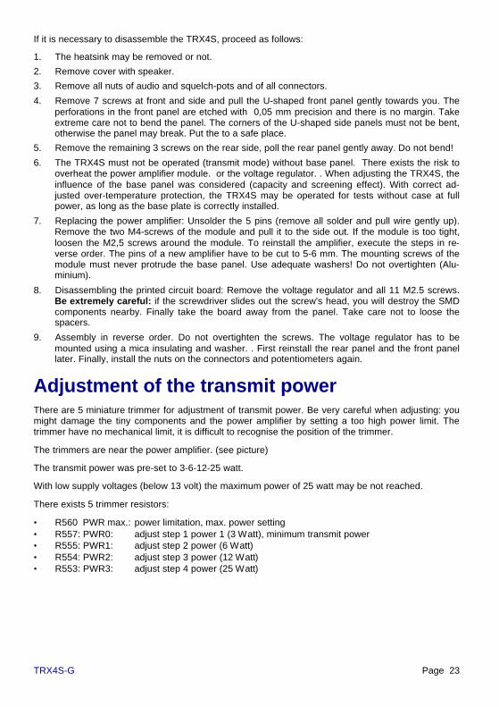
Adjustment of the transmit powerThere are 5 miniature trimmer for adjustment of transmit power. Be very careful when adjusting: youmight damage the tiny components and the power amplifier by setting a too high power limit. Thetrimmer have no mechanical limit, it is difficult to recognise the position of the trimmer.
The trimmers are near the power amplifier. (see picture)
The transmit power was pre-set to 3-6-12-25 watt.
With low supply voltages (below 13 volt) the maximum power of 25 watt may be not reached.
There exists 5 trimmer resistors:
• R560 PWR max.: power limitation, max. power setting• R557: PWR0: adjust step 1 power 1 (3 Watt), minimum transmit power• R555: PWR1: adjust step 2 power (6 Watt)• R554: PWR2: adjust step 3 power (12 Watt)• R553: PWR3: adjust step 4 power (25 Watt)

Page 24 TRX4S-G
Adjustment transmit power:
Required: a power-meter (1 to 35 watt) with 50 Ωdummy load is connected to the antenna connec-tor of TRX4S. Note: even short RG58 cables willcause a significant power drop due to attenuation.
1. program the power to step 4 (25 Watt), keythe transmitter an read the power-meter.
2. turn PWR3 (R555) to maximum clockwiseposition (min. resistance, max. power)
3. adjust PWR max. (R560) for a reading of 30watt. Turning clockwise increases power. Thesetting will limit the output power and protectthe amplifier. Avoid prolonged transmissionsat powered above 25 watt.
4. program power step 1 (3 Watt), key thetransmitter and adjust the power to 3 watt byturning trimmer PWR0 (R557). Clockwiserotation increases power.
5. program power step 2 (6 Watt), key thetransmitter and adjust the power to 6 watt byturning trimmer PWR1 (R553).
6. program power step 3 (12 Watt), key thetransmitter and adjust the power to 12 watt byturning trimmer PWR2 (R554).
7. program power step 4 (25 Watt), key thetransmitter and adjust the power to 25 watt byturning trimmer PWR3 (R555).
R560 (PWR0) defines the lowest possible powerat step 1 (3 watt). Power below 2-3 watt may bedifficult to set. With step 2, 3 and 4 (6, 12, and 25w) you may set any powers between 3 and 25 wattas desired, e.g. 3, 6, 9 and 18w. The output poweris regulated and constant within 0.5 dB over thetotal frequency range of TRX4S transmitter.
The typical output power capability of the amplifiermodule used is 35 to 40 watt at 13,8 volt supplyvoltage. It is however possible to set the trimmersto get much more power as 25 watt. This results inexcessive heating of the amplifier and may causeprogressive reduction of the power capability ortotal failure after weeks or months of operation.
Position of TX-power trimmer
Audio

TRX4S-G Page 25
Adjusting of temperature limitationNear the power amplifier module, you find a SOT23 miniature temperature sensor. Via the A/D con-verter the temperature of this sensor can be displayed by software. . Further, there exists a circuit,which will shut down the transmitter when overheated. If the PTT-input is pulled to ground and thered 'TX'-led doesn't light, check if there is a overheating condition. (If the transmitter is cold, analternative cause might be that the PLL doesn't lock because of a wrong programmed frequency).
The temperature protection is set to 62 ± 2 C. When increasing this limit, there is a risk of overheat-ing and damage. Especially the power amplifier module may be damaged by excessive temperature.
Inside the TRX4S you find a miniature trimmer for adjusting the maximum permissible temperature. .Be very careful when adjusting. The trimmer has no mechanical stop and the position cannot berecognised optically.
The trimmer R832 is located behind the audio and the squelch pot between two filters. (see picture)
Setting the temperature limit:
The temperature sensor is pre-calibrated. So, it is sufficient to measure the output voltage of thesensor to determine the temperature. For more precise adjustments, a oven would be required.
You need a high impedance voltmeter. Measure the voltage at Pin 2 of U250 (right top) or at the tapof trimmer R832 (left top). Adjust the following settings:
Temp. Max °C Measure Volt
(20) (2,81 V)40 3,00 V45 3,04 V50 3,09 V55 3,13 V60 3,17 V
62,5 3,19 V65 3,21 V70 3,25 V75 3,29 V80 3,33 V
Adjusting of rf carrier de-tectionThe receiver-IC's of TRX4S have a RSSI-output (radiosignal strength indicator), where you can measure avoltage, which is proportional to the rf input level (indB). There exist two separate RSSI-signals, one forwide and one for narrow bandwidth signal reception.
If the RSSI-signal exceeds a pre-set level, the green'RSSI-LED will light. Simultaneously, pin 6 of the 6-pinmini-DIN data-connector is pulled low.
With the trimmers R263 (DCD level narrow) and R264(DCD level wide), the trigger voltage for carrier detectcan be adjusted. separately for narrow and wide
The precision achieved by this way of meas-urement is approx. 5° C. Theoretically, you mayset the trimmer to voltages from 2,97 to 3,60volt, which corresponds to a temperature rangefrom 38 to 125 C.

Page 26 TRX4S-G
mode. The trimmer can be found near the 6 pin mini-DIN connector inside the case.
Procedure: apply an unmodulated carrier with the desired strength to the antenna input and adjustthe trimmer R263 (DCD level narrow) and R264 (DCD level wide) so, that the led just flickers. Foradjusting DCD-level narrow you will have to select a frequency in narrow mode, equivalent for 'wide'-setting.
The setting does not influence the reception of data signals in any way. Only the function of the greenDCD-led and the DCD-output (pin 6) is affected.
The adjustment range goes from 'permanent DCD' (ccw) to 'never DCD detect' (clockwise). Betweenthe limits, the adjustment is approximately linear with the logarithm of the input power. The triggerpoint may be adjusted to any input signal strength within the dynamic range from –120 dBm = 0,2 µVto –50 dBm = 1 mV (narrow) or –115 dBm = 0,5 µV to –40 dBm = 2 mV (wide).
If the DCD is set to a very low level, the presence of additional noise (QRM, QRN) or the use of anpreamplifier may increase the idle input signal level and cause a permanent DCD-display. Set thelevel to a higher level to consider the additional signal.
Adjustment of the modulation (deviation)The audio input voltage (mini-DIN-connector pin 1) for appropriate deviation is set to 0,5 volt peak-peak. If your packet-radio-controller supplies more or less voltage, you should adjust the signal at theTNC but not at the TRX4S.
The modulation input sensitivity can be adjusted separately for narrow and wide mode. The adjust-ment range goes from few mV up to approx. 0,8 Vpp (narrow) or 3 Vpp (wide). Do not use too smallsignal levels in order to reduce additional noise.
The trimmers can be found behind the mini-DIN-connector (see picture)
For best setting in narrow mode, adjust R241 so, that you measure 0,6 Vpp at point M250.
For best setting in wide mode, adjust R211 so, that you measure 4,0 Vpp at point M250.
Alternatively, you can use a test receiver with deviation-meter to set directly the correct deviation.
Note: too much input voltage causes excessive deviation on the transmit signal. This will causeproblems due to distortion at the receiving station if the bandwidth of the receiver is smaller as thoseof the transmitted signal.
Adjustment of the modulation (compensation)The transmitter of TRX4S is modulated using atwo-point modulation circuit. The high frequencyparts of the modulating signal is applied directly tothe varicap diode of transmitter-VCO, the lowfrequency parts will also modulate the referenceoscillator. So, it can be made sure, that the PLLdoes not compensate the low frequency parts ofthe input signal and that modulation down to verylow audio frequencies is possible.
With trimmer R253 you may adjust the ratio of thetwo modulation indices for the two modulators. .You find it between the 7-segment-display and theaudio volume potentiometer.

TRX4S-G Page 27
For adjustment, apply a square wave signal (0,5 Vpp) with approx. 150 Hz frequency to the data inputof radio and watch the demodulated signal at the data output of a reference test receiver. (withappropriate bandwidth capability)
If the reference quartz modulation is not enough, (trimmer R253 turned too much ccw), you find adeviation from pulse flatness. After the pulse edge, the pulse of the received signal drops.
With too much modulation applied to the reference quartz, (trimmer R253 too far cw), you find
also a deviation from pulse flatness, but the voltage continues to rise slow after the edge.
If the compensation is adjusted properly, the rising and falling edges are at the same voltage leveland the pulse top is not tilt.
Adjustment of the reference quartzTransmit and receive frequency are derived from two quartz oscillators: the reference quartz deter-mines the VCO-frequency, (approx. 350 MHz) and is primary responsible for precision of the trans-mit frequency. and stability. The 60,3 MHz oscillator participates also in generating the correct fre-quency.
The frequency drift of the oscillators of TRX4S is approx. 2·10-6. Adjustment makes only sense, is afrequency counter with a precision of 2·10-7 or better is available. We recommend counters withtemperature controlled quartz oven or counters with external synchronisation to a radio frequencystandard (DCF77, WWV etc).
The frequency of the reference oscillator may be measured at pin 7 of the microcontroller IC or(without opening the case) at pin 9 of the REMOTE-connector. With trimmer R312 (see picture) thefrequency may be adjusted to 12 800 000 Hz exactly. The TRX4S should be in receive mode and nomodulation signal must be applied. Adjust the frequency to ± 1 Hz precision, which corresponds to30-40 Hz error at 430 MHz operating frequency.
Alternatively, you may measure the frequency of one of the both VCO. Program any frequency (e.g.435,000 MHz) and subtract the if frequency of 71,000 MHz. The resulting RX-VCO-frequency (e.g.364,000 MHz) can be measured at M639 (behind the antenna connector, see picture 'output poweradjust upper right).
too little modulation of reference quartz too much modulation of reference quartz

Page 28 TRX4S-G
Do not adjust the reference oscillator by measuring the transmit frequency only, as this frequencydepends on the precision of the other oscillator as well.
Adjustment of the local 60,3 MHz oscillatorAfter precisely adjusting the reference quartz to 12.8 MHz, youmay adjust now the 60,3 MHz oscillator by measuring the trans-mitter output frequency. Tuning coil L400 (see picture 'compen-sation'), this oscillator frequency can be set within a narrowrange to the correct reading. The 1,5-fold of the quartz frequencycan be measured while transmitting at M425 (90,450 MHz). Youfind this point directly near the white transmit mixer, 10 mmbehind the audio volume potentiometer.
Adjustment of TX-VCOWith a TX-VCO control voltage of 2,5 volt, the VCO shouldoscillate in the centre of the band. So, if the centre frequency isproperly adjusted with C330 (at the end of the VCO-line, behindthe squelch pot, see picture lower right) the voltage at M325 (seepicture, middle left) will read 2,5 volt The transmitter may bedisabled by miss-tuning L406 while measuring the VCO fre-quency.
Adjustment of RX-VCOWith a RX-VCO control voltage of 2,5 volt, the VCO shouldoscillate in the centre of the band. So, if the centre frequency isproperly adjusted with C621 (at the end of the VCO-line, in thecentre of the board, see picture upper) the voltage at M620 willread 2,5 volt.
Adjustment of quadrature coilThe coils L721 (narrow) and L750 (wide) are responsible forproper fm-demodulation. Adjustment is easy: connect an oscillo-scope to the data output of the receiver and adjust for optimalsymmetry of the receiver noise signal. The receiver input re-mains open or is terminated with a 50 Ω resistor.
If-filter adjustWe recommend not to do any adjustments at the if filters .
L710 and L711 are simply adjusted to maximum RSSI reading innarrow mode
The coils L665 and L682 have to be adjusted carefully. They areresponsible for proper input and output matching of the 71 MHzquartz filter. Improper filter matching results in changing theamplitude and phase response of the filter, causing excessivedistortion to the data signal. . With a suited sweeper you may

TRX4S-G Page 29
optimise the amplitude of the if filters, but not the phase response. It is a good idea to adjust the filtermatching by observing the eye pattern at the receiver output. While receiving a 153 kbaud signal, youwatch the eye pattern and adjust L665 and L682 for optimal symmetry and eye.
Adjustment of 90,45 MHz stagesThe 60,3 MHz oscillator is set to the exact frequency by adjusting L400 (see above).
L406 is adjusted with the transmitter keyed up for sufficient drive of the frequency divider U410. If thecoil is not adjusted, the divider doesn't work and there will be no 30,15 MHz signal present at thedividers output.
The 90,45 MHz is generated by tripling the 30,15 MHz at the output of the divider. At M425, the coilsL420 and L422 are adjusted to maximum signal. The band filter at 90,45 MHz (L415 / L416) is set tomaximum output too.
Adjustment of transmitter driver 435 MHzThe mixer U430 generates the 435 MHz transmit signal, which will be amplified to 0.5 watt in the 4stage driver amplifier. The attenuators between the amplifiers make sure, that the amplifiers workabsolutely stable with constant load and perfect matching.
For coarse adjustment, the power regulation of the power amplifier is disabled. If the regulation wouldbe active, a change in driver power would be compensated by the regulation and you could notmeasure a difference when tuning the driver stages. Set the transmit power to level 4 (25 watt) andturn the corresponding trimmer R555 to maximum power. Now reduce the output again by setting thepower limit (R560) to 5-10 watt output power at the antenna connector. Now, the power regulation isdisabled. The value of the output is now proportional to the driver input and you can do the adjust-ments for the driver stages without problems. Be sure to set the trimmers to the old settings after theadjustment of driver.
Do not turn the brass screws of the helical filters. A readjustment is difficult. If all filters are tuned tomaximum power at centre frequency, you will find a significant power drop at the ends of the band.Try to adjust the filters in a way to achieve flat response over the total frequency range but steepedges at the band limits. After the adjustment to maximum power at centre frequency, turn one of thethree filters some MHz up and one some MHz down to get a flat response within the total frequencyrange and a sharp cut-off at the frequency limits.
Trimmers C455 and C467 are set to maximum output at centre frequency.
After successful coarse adjustment, re-set the power limit and regulation back to the previous value.
For fine adjustment of the amplifiers you won't need a wattmeter. If the power regulating trimmers areset to 3-6-12-25 watt with a limit at 30 watt, the measurement of the regulated bias supply of thedriver stage in the module will do. Program the power range to level 2 or 3 (6 or 12 watt) and meas-ure the voltage at the middle pin of IC U560 (voltage regulator at the base plate next to the amplifiermodule. The lower the voltage, the lower is the amplification of the driver to achieve the selectedoutput level and the higher the driver stage power level. Adjust the drivers now to minimum readingof the regulated bias voltage at U560.
If the power regulation doesn't work stable at low power levels (3 watt), the driver power might be toohigh. Reduce driver power by setting the filters of the driver stages off resonance.

Page 30 TRX4S-G
Adjustment of final amplifier and lowpass filterThe 5 coils L523, L528, L530, L532 and L545 are part of the 3 stage lowpass filter and the transmit-receive antenna switch. with the pin-diodes CR541, CR545 and CR528. Adjustment of these filters isnot necessary. The attenuation of the filters in the pass band cannot be reduced. The harmonics ofthe transmitter are sufficiently suppressed and cannot be reduced by changing the filters.
The same is true for the coils L530 and L545 in the receiver input path.
Update of firmwareIf it becomes necessary to change the firmware, stored in the microcontroller, gently pull the 18-pinIC U800 out of the socket and insert the controller with the new firmware.
Disabling the 7-segment displayThe current drain of the 7-segment display is approximately 15 mA (the complete receiver needsapprox. 250 mA). Directly in front of the display you find a jumper to disconnect the display powersupply to save 15 mA.
Switching temperature / power readingThe microcontroller of TRX4S has two analogue inputs. One of them is used for measurement of theRSSI voltage, the other is normally used for reading the voltage across the temperature sensor, butcan be set to power measurement as well.
Problem: you may read the temperature at any time. But measuring the transmit power makes onlysense if the transmitter is keyed while measuring. As the PTT is controlled only by the attachedpacket-controller, which does not communicate with the TRX' microcontroller, measuring the realoutput power is difficult. For this reason, the default setting of TRX4S is temperature display.
With the default setting, S0=? will read the temperature of the amplifier. But it is possible to changethe setting to power reading if necessary. Two steps are necessary:
1. The input of the A/D converter is connected to the temperature sensor by the jumper M830/M831by a 100 kΩ miniature resistor. Remove the resistor (outer contacts of the 3 pin jumper) and connectM831 and M832 (middle contact and outer contact towards front) by the 100 kΩ resistor. Now, theA/D converter input is connected to the RF measurement rectifier. .
2. For temperature and power measurement calibration, there exists two different lookup tables inEEPROM.. Which of the two tables will be used when executing the S0=? command, depends on thevalue stored in address 0181H of EEPROM. This memory location is default set to 01H, the controlleruses the table stored at the addresses 0400H to 04FFH to convert voltage into degree Celsius. If thejumper is changed to power measurement, the byte in 0181H has to be set to 00H using the 'POKE'command. Normally, the conversion table for power measurement is empty and has to be calibratedfirst.
TRX4S-G Page 31
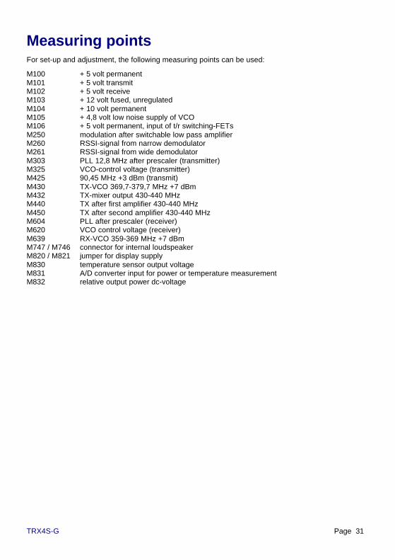
Measuring pointsFor set-up and adjustment, the following measuring points can be used:
M100 + 5 volt permanentM101 + 5 volt transmitM102 + 5 volt receiveM103 + 12 volt fused, unregulatedM104 + 10 volt permanentM105 + 4,8 volt low noise supply of VCOM106 + 5 volt permanent, input of t/r switching-FETsM250 modulation after switchable low pass amplifierM260 RSSI-signal from narrow demodulatorM261 RSSI-signal from wide demodulatorM303 PLL 12,8 MHz after prescaler (transmitter)M325 VCO-control voltage (transmitter)M425 90,45 MHz +3 dBm (transmit)M430 TX-VCO 369,7-379,7 MHz +7 dBmM432 TX-mixer output 430-440 MHzM440 TX after first amplifier 430-440 MHzM450 TX after second amplifier 430-440 MHzM604 PLL after prescaler (receiver)M620 VCO control voltage (receiver)M639 RX-VCO 359-369 MHz +7 dBmM747 / M746 connector for internal loudspeakerM820 / M821 jumper for display supplyM830 temperature sensor output voltageM831 A/D converter input for power or temperature measurementM832 relative output power dc-voltage

Page 32 TRX4S-G
Remote-Control connectorAt the front, you find a 10-pin receptacle 'remote' to control all functions of TRX4S.
You need a 10 pin (1/10 inch or 2,5 mm spaced) male connector. A possible remote control unit maybe attached to the front of the TRX4S by spacers with M2.5 screws, which fit into the base and coverplate threads and with 10 pins to connect the remote control jack.
The following signals are available:
Ground, + 5 volt, clock for power supply of a remote control unit
Pin 10 (oriented to centre of the front panel) is connected to ground, pin 8 supplies 5 volt from theinternal voltage regulator of TRX4S. The maximum permissible current drawn is 150 mA.
The reference oscillator (12,800 MHz) is present at pin 9. Here you may attach a frequency counterfor adjusting the transceiver frequency reference, but the buffered signal may be used for supplying aclock to an external processor of a remote control circuitry. A separate oscillator for such a circuitshould be avoided, as this may cause additional interfering spectral lines within the receivers fre-quency range.
Push button functions 'up' and 'down' for channel selection
The signals for switching the channels up and down are accessible at the remote control connectorpins 4 (down) and 5 (up). Note: the keys are not switched to ground but to + 5 volt!
3-wire interface for output of 7-segment-display, power-setting, mode
With every channel change, a 16-bit word is output at the three pins 1 (data), 2 (clock) and 3 (en-able). Here, normally a shift register (serial in parallel out. e.g. 74HC595) is connected. After outputof a hi or low signal at pin 1 (data), this information is shifted into the register by a low to high transi-tion of the pin 2 (clock). After all 16 bit have been output in that way, the total information is latchedwith the rising edge of the pin 3 (enable) line. Now, all 16 bit are available at the parallel output of theshift registers.
Here the description of the 16 bit (shown in consecutive order first to last)
1. Bit (not used) 9. Bit 7-segment: DP2. Bit (not used) 10. Bit 7-segment: g3. Bit (not used) 11. Bit 7-segment: f4. Bit (not used) 12. Bit 7-segment: e5. Bit power level 4 13. Bit 7-segment: d6. Bit power level 3 14. Bit 7-segment: c7. Bit power level 2 15. Bit 7-segment: b8. Bit mode narrow 16. Bit 7-segment: a
If only one 8-bit shift register is used, the bits 1 to 8 of the information are lost. The register will showonly the last 8 bit (9 to 16) which can be used for a external 7-segment display. In most of the appli-cations, the bits 1-8 are not necessary and may be omitted. A BCD to 7-segment decoder is notnecessary, as the 7-segment patterns are stored in and generated by the microcontroller of TRX4S.
With bits 5 to 8 you may control LED's to display the current output power level and wide/narrowmode. The bits are sent with approx. 100 kbit/s in a synchronous mode (11.0 µs per bit). To built asimple decoder, you may copy the shift register circuit of TRX4S

TRX4S-G Page 33
serial asynchronous 9600 baud interface for programming etc.
Using pins 6 (serial output) and pin 7 (serial input), you can execute all commands of TRX4S asdescribed on page 18. The interface is parallel to the external rs232-interface, but the signal levelsare different. (voltages referred to pin 10, ground)
• serial output (pin 6): serial 9600 baud signal from TRX to remote control unit.Idle (stop bit): HI (5 volt), data (start bit): LO (0 Volt). 1 start bit, 1 stop bit.
• serial input (pin 7): serial 9600 baud signal from remote control unit to TRX4S.Idle (stop bit): HI (5 volt), data (start bit): LO (0 Volt). 1 start bit, 1 stop bit.For sending data, a open-collector output will do. The input is de-coupled to the external rs232by a diode. Note: external programming via rs232 and programming via the remote control con-nector cannot be done simultaneously. If pin 7 is pulled to + 5 volt with a resistor (> 47 kΩ), theremote control unit can read the data, which is transferred from the rs232 to the TRX at the se-rial input of the TRX remote connector. In idle state, pin 7 must be open or pulled to + 5 V. Ifpulled to ground, the external rs232 programming won't be possible.
DETAILED CIRCUIT DESCRIPTIONWe won't describe every stage of the circuit. Most of the TRX4S circuits are common amplifiers,filters or oscillators. We want to explain only those circuits, with special or unusual functions.
Reverse polarity protection: the safest protection against reverse polarity of the supply voltagewould be a diode in series with the supply. As there would be a voltage drop of 0,3 to 0,7 volt, thissolution would be unfavourable. We use a reverse biased parallel diode with 40 A current capabilityto blow the fuse. Using fuses with higher current rating results in the risk to blow the diode first andso destroying the transceiver when reversing supply voltage.
PTT-input: the PTT-input switches the transmitter via a 74HC132 Schmitt-trigger. As soon as thevoltage at the PTT input drops below 2 Volt, the transceiver will switch to transmit, rising above 3 voltwill switch to receive again. When not connected, there will be a voltage of + 5,0 volt at pin 3 of thedata connector. The PTT-input is protected by a 200 kHz lowpass filter against rf interference. Whenkeying the transceiver by an open-collector output, this low pass filter will cause a delay of the re-ceive-transmit switching of approx. 5 µs, the switching from transmit to receive will take 50 µs. If thePTT is controlled directly by a ttl-output, the delay will be constant 5 µs in both cases.
Transmitter supply voltage: The 5 volt transmitter supply voltage is switched by a FET-switch with5 amp current capability and a low Ron of 60 mΩ. The FET switches immediately. It would not bepossible to have the switch before the voltage regulator, because the settling of the common 7805regulators needs too long (about 1 ms and more). The transmitter supply is only switched on if theTX-PLL is locked. A unlocked PLL would oscillate on a undefined frequency and result in interferenceor unwanted transmissions. The led 'TX' lights if the TX is supplied with 5 volts and PLL is locked.The driver stages and the pin-diode antenna switch are not affected by the locking condition of thePLL. If the TX-frequency is programmed wrong, the PLL won't lock and remains disabled.
Receiver supply voltage: The receiver is switched on after transmission with a little delay to makesure, that the transmitter is totally shut of when reception starts again. As with the transmitter, theRX-supply is only switched on (green RX-led lights), when the RX-PLL is locked. If the RX-frequencyis programmed wrong, the PLL won't lock and the receiver remains off.
Voltage regulator for PLL: The presence of noise on the LPL's supply voltage would result in ex-cessive phase noise (unwanted modulation) of the transmitter and receiver output. For supply of thetwo PLL circuits, the normal voltage regulators are not suited. The TRX4S uses a simple transistorfor filtering the noisy 5 volt internal supply. The transistor amplifies the voltage delivered from the 5volt supply via a lowpass filter with 0,5 Hz corner frequency.

Page 34 TRX4S-G
Power supply of the audio amplifier: The operational amplifiers of the modulation and audiostages are supplied symmetrically with +/- 5 volt. The internal +5 volt is used as the ground for theamplifiers, the transceiver ground is used for negative supply and a regulated voltage of 10 volt isused for positive supply. The +10 volt come from a standard 5 volt regulator with its ground pin con-nected to 5 volt. The regulated 10 volt will also supply the LM386 audio amplifier for the speaker.
Switchable 90,45 MHz oscillator: A stable oscillator needs approx. 10 ms to start oscillating or tolock on a frequency. Hence, all oscillators in a fast data transceiver have to oscillate permanently.The problem is, that the oscillators, needed for generation of the transmit frequency, will cause aspurious signal exactly at the receiver input frequency in simplex mode (f TX = f RX). The problemwas solved by using a 'TXD-null-oscillator': The transmit frequency is generated by mixing of theconstant PLL frequency with a 90,45 MHz auxiliary frequency, derived from a frequency divider witha fix 60,3 MHz quartz. By switching off the frequency divider, the 30,15 and the tripled 90,45 MHzsignal vanishes completely, however, all quartz oscillators remain on. So, there exists really no spuri-ous signal at the transmit = receiver frequency when receiving.
Diode mixers: The TRX4S uses two high quality diode mixers 'ADE13'. The local frequency inputlevel is as high as +7 dBm = 5 mW to achieve excellent large signal capability of the receiver and ahigh level intercept point. (IP3: 17 dBm = 50 mW)
Amplifiers general: All rf amplifiers use monolithic amplifiers type ERA3. These amplifier IC aresuited for up to 3 GHz, have a input and output impedance of 50 Ω, which makes matching easy. Thegain of approx. 20 dB per amplifier is reduced by pi-attenuators between the stages to 14 to 17 dB toimprove stability and matching of the amplifiers. With a noise figure of 3,8 dB, these amplifiers maybe used as sensitive preamplifier as well, but more important is the excellent large-signal capability ofthese amplifiers. (IP3 = 23 dBm = 200 mW). The amplifiers may be driven with up to 20 mW (1 volt)rf at the antenna input without damage.
Power amplifier: As power amplifier, the Toshiba M57729 is used. According to the datasheet, it iscapable to output 45 dBm = 35 watt rf power, typical values of much more have been measured. With44 dBm = 25 watt transmitter output power, there is enough power margin to keep the output con-stant over the total frequency range. The harmonic frequencies, measured directly at the moduleoutput are 20 dB below the carrier (24 dBm = 0,3 W).
Lowpass output filter and antenna switch: The harmonic frequencies of the transmitter signal aresuppressed by a lowpass filter. The attenuation of the first harmonic frequency at 870 MHz with athird order filter is approx. 60 dB. This gives a total suppression of 80 dB = -36 dBm = 250 µW re-ferred to the carrier. The attenuation of the third harmonics is even better. In series with the transmitsignal path, there is a high power pin diode, which disconnects the transmitter output from the an-tenna when receiving. The diode is suited for rf power up to 100 watt and has a rf-resistance of 0,5 Ωat 30 mA control current. The antenna signal passes a third order filter on its way to the receiverinput. When transmitting, the rf from the transmitter is switched to ground with two pin-diodes. Thehigh attenuation of this switch makes sure, that the receiver input is not overdriven or even damagedby the high power transmitter levels. In most transceivers, only one diode is used for keeping thetransmitter power away from the receiver input, which results in a much stronger rf signal at thesensitive preamplifier input.
Transmit power regulation: Directly at the power amplifier module output, the rf is rectified by acapacitor and fast low-capacity Schottky diode. The rectified rf voltage is filtered and controls via a dcamplifier and a switchable voltage divider the reference input of a programmable voltage regulatorLM317T, which supplies the drivers. When rf output power drops, the voltage across the dividerdecreases and the supply voltage of the drivers increases to give more power. With 4 trimmers, thevoltage divider can be switched to program one of 4 pre-set power levels. When in receive mode,the voltage divider is pulled to +5 volt to shut down the driver supply completely.
VCO circuit: The VCO frequency is generated with a newly developed IC, giving a signal with per-fect spectral purity at a high power level. For inductor, there is no coil used but a λ/4 semi-rigid-resonator. This avoids interference and acoustic-mechanical influences to the VCO tank circuit andhas better temperature stability compared to wounded coils.

TRX4S-G Page 35
Data-output (demodulation): The outputs of the both demodulators (wide, narrow) are selected byan analogue switch to pin 4 of the data connector. When transmitting, both switches are open andthe output is disabled. Pin 4 is dc decoupled by a 470 Ω resistor in series with a 22 µF capacitor. .
Data input (modulation): The data input (Pin 1) goes to two low pass amplifiers with different cornerfrequencies. for wide and narrow. The outputs are switched to the modulating circuits when trans-mitting. In receive mode, the modulation is disabled. Otherwise, the reference oscillator, which isused for reception too, would be affected by the data in signal, causing interference to the receivedata.
Squelch: The AF-noise of the narrow demodulator is filtered at 11 kHz and rectified with CR739. Ifthe noise amplitude exceeds a certain value, which can be set with the squelch pot R733, the audiosignal is switched to ground by an analogue switch.
Audio-amplifier: The control speaker is driven by the amplifier IC LM386. With 10 volt supply volt-age this amplifier delivers 0,7 Watt into a 8 Ω load. The built-in speaker is disconnected if an externalspeaker jack is plugged-in.
Comparator for rf-DCD: The RSSI-signals of the two receivers are compared to an adjustable dcvoltage (trigger level). The output of one of the comparators controls only the green led 'RSSI-DCD',the other is the pin 6 of the data connector. The trimmer for setting the DCD trigger and the RSSI-outputs of the if amplifiers are switched by analogue switches.
A/D converter for RSSI, temperature and power measurement: The microcontroller possesses twoanalogue compactor inputs. One of the comparators is used for RSSI measurement, the other fortemperature or power measurement. The non inverting input of the comparators is connected to a 22nF capacitor, which is charged to +10V by a 100 kΩ resistor within 2 ms time. The capacitor is dis-charged by a FET to zero volts and the microcontroller measures the charge-time, which is neededuntil the voltage across the capacitor becomes equal to the voltage to be measured The time ismeasured as a value within the range between 1 and 255 and converted by a lookup-table in to thedisplayed value. (dBm. °C)
RS232-interface: the UART (asynchronous transmitting and receiving) is performed by software inthe microcontroller. The baudrate (9600 baud, 1 start, 1 stop bit, no parity) is fixed and cannot bechanged. For level translator, the well known MAX232A is used. With its built-in charge pump, thisdriver generates the +/- 10 volt. The serial input and output is filtered with a r-c-r lowpass filter toreduce rf interference with the serial interface connector. The rs232-input is pulled to -10v with a 10kΩ resistor to give a 'low' signal (stop bit polarity) when no computer is connected. This is importantto control the TRX4S controller via the external rs232 interface parallel to the remote control con-nector. As the charge pump of the MAX232 uses high current and high frequency pulses for gener-ating the +/- 10 volt, the 5 volt supply of the MAX232 is decoupled from the transceiver by a 10 kHzlowpass filter.
Temperature sensor and over-temperature protect: At the power amplifier module's mountingscrew, there is a tiny KTY92 temperature sensor with a nominal resistance of 2000 Ω at 25 °C. Thetemperature coefficient of this semiconductor sensor is 7,9 *10-3 K-1. Hence, at 70 °C the resistanceincreases to 2780 Ω, the voltage across the voltage divider R830 – U830 rises accordingly. As soonas the voltage reaches the value, set by trimmer R832, the op amp U250 pulls the transmit enablesignal to ground via transistor Q835 and disables the transmitter immediately. After cooling down, thetransmitter returns back to normal operation.
Channel display: The channel number is displayed by a 7-segment-display TDSR3160 (commoncathode). With 1,5 kΩ segment resistors the total current is 4 to 16 mA depending on the figuredisplayed. The display is controlled by a 8 bit serial-parallel-converter (shift register), the 7-segment-code is stored in the microcontroller firmware.
EEPROM: The 8 pin SMD-EEPROM has a storage capability of 16 k Bit = 2048 byte. The addressesfrom 0000H to 017FH are used for storing the 16 frequency records, 0200H to 03FFH contains the

Page 36 TRX4S-G
lookup tables for measuring conversion. The EEPROM is accessed by a 2-wire interface. The firm-ware allows to read from and write to any address by the PEEK and POKE commands.
REGULATIONS, ETC.All copyrights on firmware, PCB-layout and schematics of TRX4S are reserved to SYMEK GmbH orIng. Büro Kumm, Stuttgart. Parts of the circuit are covered by patents pending.
Parts of this manual may be published if there is a reference in the bibliography. It is our concern tocontribute to packet-radio by offering new and powerful equipment and to inspire many radio ama-teurs by this fascinating technique
When properly used, the TRX4S complies with the regulations of German EMVG and bears the CE-sign. A German BZT-approval, which would be necessary for commercial use does not exist. So, theuse of the transceiver is limited to licensed amateur radio operators as transmitter.
The user will need special knowledge on electronics and communication techniques for operating thetransceiver, as it is demanded to pass the amateur operators licence exam. The transceiver and thedescription are not made to be used by people without technical knowledge. .
For proper use, it is necessary to connect the transceiver to a suited power supply, to connect asuited signal source for modulation, which meets the requirements described in this manual. , toconnect a suited antenna with according feeding cables. For not to deteriorate the EMV-values, youmust connect only those subassemblies to the remote-control connector, which are recommended bythe manufacturer. additional modules have to be connected using the original connectors. Make sure,that the cables connected are not interfered by strong electro-magnetical fields (speaker, modulation,power supply, antenna).
The user is - as with any other amateur radio transmitter - obliged to make sure, that no person isendangered by the radio frequency power, produced by the transmitter. If you are not sure about theexisting regulations for operating a transmitter or high frequency equipment, see your local authori-ties for telecommunications. For Germany, see the information published by Regulierungsbehördefür Post und Telekommunikation (http://www.regtp.de).
The actual German law allows everybody to own or trade with the TRX4S transceiver. This is alsotrue for using the TRX4S as receiver only. . If used as transmitter, the responsible user has to have apermission (e.g. amateur radio operators licence).
We are nor liable for any damage, which might be caused by the use of the transceiver, nor for erro-neous information or misprints in the manual.

TRX4S-G Page 37
SCHEMATICS, PART LOCATION
Location of the parts (left half)

Page 38 TRX4S-G
Location of the parts (right half)

TRX4S-G Page 39
Schematics TRX4S (AF, TX, power-supply)

Page 40 TRX4S-G
Schematics (receiver, control)

TRX4S-G Page 41
WHAT TO DO IF THE TRX4S DOES NOTWORK?Here some common user errors: :
Malfunction: PTT is keyed but the red 'TX'-led remains off. No transmit power.Cause: wrong transmit frequency programmed or amplifier too hot.
Malfunction: 'RX'-led remains off, no receptionCause: wrong receive frequency programmed.
The TRX4S design is proven good. The components are reliable for industrial use, the printed circuitboard is of first class quality and all transceivers are tested thoroughly. However, there is a chancethat the equipment would fail.
If you have done any modifications with TRX4S, please make sure that these modifications are NOTthe cause for the malfunction and remove all modifications again. If there are changes or attempts torepair made, the warranty claim is void.
For the following damage there is no claim for warranty repair:
• Overload of power supply by over-voltage (over 16 volt), causing failure of the voltage regulatoror the power amplifier module.
• Destruction caused by reverse polarity of power supply or by use of a wrong fuse.
• Destruction of the power amplifier, caused by misadjusted over-temperature protection or useof unsuited rf load (e.g. open antenna connector), bad SWR)
• Too high input level at receiver input, damage of the preamplifier
• Destruction of serial interface caused by over-voltage at the rs232-connector
• Destruction of the audio signal amplifiers caused by over-voltage at the data-connector
• Destruction of the audio power amplifier caused by over-voltage or short circuit at the speakerconnector
• Destruction of components caused by over-voltage at the REMOTE-connector.
• Any kind of mechanical damage
The warranty period is 1 year from purchase, excluded are damages caused by the customer.
Please give us a detailed description of the failure and what has happened before the failure oc-curred. The repair could be done faster and more easy.
We hope, you enjoy the use of the TRX4S high speed data transceiver.

Page 42 TRX4S-G
INDEX10 volt external supply (+10V) Pin 5 1260,3 MHz oscillator 27, 297-segment display 307-segment-display 3590,45 MHz oscillator 34A/D converter 25, 35ac filtering of supply 12acknowledge of record 18adapter rj45 15adapter rj45-sub-d 16adjust 90,45 MHz stages 29adjust driver stages 435 MHz 29adjust lowpass filter 30adjust of VCO centre frequency 28adjust quadrature coil 28adjust TX power 24adjusting the 60,3 MHz oscillator 28adjustment of referencequartz 27adjustment of transmit power 23adjustments 21AF-bandwidth 14amateur radio operators 36amateur-radio transmitters 36ambient temperature 15Amiga 8amplifiers 34analogue switch 35antenna 6antenna connector open 41antenna switch 14, 34Apple 8ASCII-configuration (Hyperterm) 17assembly 23Atari 7attempt to repair 41audio amplifier 14, 34, 35audio input voltage 26base panel 23baudrate 7, 35buttons 'up' and 'down' 32BZT-approval 36Cable (data) 10cable PC-TRX4S 15calibration tables 30capacitor, 12v supply 12car battery supply 12Carrier detection (RSSI-DCD) 11carrier suppression TX 15case, opening 22CB 12v power supplies 12CE-sign 36channel data record 18channel display 35channel identifier 18channel selection 8, 19channel settings 8channel spacing 14channel-selection 6charge pump 35check of record syntax 18
com-interface 7command 8commands of TRX4S firmware 18commercial use 36communication between terminal andtransceiver 8comparator for rf-DCD 35compensation 26config-file of terminal program 16configuration file TERM.cfg 16connect via (Hyperterm) 17connecting cable TNC-TX 10connection of remote control 6control voltage (VCO) 28controller 30conversion tables 21CONVERSION VOLT, WATT, DBM 46cooling 15copyright 36corner frequency (modulation) 35current channel 8, 19damage 36damage of the preamplifier 41damage, mechanical 41data connector 6data input (modulation) 35data transfer 17data-output 14data-output (demodulation) 35dB (µµV) 46dBm 46dc across data-input 11dc decoupling (data output) 35dc input supply 12DCD Level 25DCD-output 26default set-up 6defect 41demodulator 10demodulator (narrow) 35deviation 11, 26deviation meter 26dimensions physical 14diode-mixer 34disabling the 7-segment display 30disassembling the TRX4S 22disc 7distortion 26driver stages 435 MHz 29driver supply 34dummy load 24duty cycle 15dynamic range of DCD 26dynamic range rf 14EEPROM 18, 35EEPROM address 20EEPROM-programming 21EMVG-regulations 36ERROR 20error messages 20Fahrenheit 19fan 15FET-switch 33filter capacitor 12v supply 12filter, amplitude and phase response 28

TRX4S-G Page 43
firmware version display 20fm-demodulation 28frequency 18frequency counter 27frequency divider 29frequency drift / error 14frequency memory 18frequency of reference oscillator 32frequency of reference quartz 27frequency of the VCO 27frequency of VCO 27frequency precision 27frequency range 14frequency range (data out) 11frequency range of data input 11frequency setting 14front panel 6front panel removing 23fuse, 12 volt supply 12guard time 8handshake 7harmonic suppression 15heatsink 22Hyperterm 8Hyperterm (Windows95/98) 17if filter coils 28if-adjust 28input errors recognition 20input impedance (data) 11input signal maximum 14input voltage (antenna) 19input voltage (audio) 26inputs and outputs of TRX4S 11installing the heatsink 22interface cable 7interface f. 7-segment-display 32interface parameter 7interface to computer 6interference 36interference, rs232, filter 35intermodulation, 3rd intercept 34isdn-cable 15key 'up' 9keying the transmitter 33knowledge, special 36knowledge, technical 36KTY92 35large signal capability 34law - permission 36led 'TX' 25level translator rs232 35limitation of TX power 23linefeed delay (Hyperterm) 17local echo 17lookup-table 19low audio frequencies 26low corner frequency (data out) 11low pass amplifiers, modulation 35lowercase characters 20lowpass amplifier 11lowpass antenna filter 34lowpass filter adjust 30manual 36manufacturers information in EEPROM 21
matching the 71 MHz quartz filters 28matching TNC to TRX4S 26MAX232A 35maximum temperature 25measuring points 31memory map of EEPROM 21memory, EEPROM 35mica insulation 23microcontroller 18, 30, 35microphone amplifier 12miniature trimmer 23mini-DIN-connector 10minimum output power 24minimum TX power 23mirror frequency 14misprints 36mode 18mode wide/narrow 8modem connector 11modems 10mod-input 15modular-cable 16modulating voltage 11modulation 10, 26modulation amplifier 11modulation input sensitivity 26modulation-input (Data in) 11monolithic amplifiers 34new connect (Hyperterm) 17noise at the PLL supply 33noise figure 34number of current channel 8oscillator frequency drift 27output impedance (data out) 11output power 18, 34output power display 19output power measurement 30output power TX 15output voltage 11overheating 25overheating the power amplifier 23overload at rf input 34over-temperature protect 14, 23, 35, 41over-voltage 41packet rate 14packet-radio-controller 26packet-radio-controller (TNC) 10parallel diode 33part location 37patents 36peek: read byte in EEPROM 21permission 36phase response of if filter 28pi-attenuator 34pin 6 of modem connector 11pin diode 34pin-diode antenna switch 33poke: write to EEPROM 21polarity, reverse, protect 33polarity, supply-voltage 12potentiometer 23power 24power amplifier 24, 34power amplifier replacement 23
Page 44 TRX4S-G
power consumption 30power display 30power drain, supply 14power limitation 23power margin 34power regulation TX 15power supply 12, 14power-cycle 8power-on 8preamplifier 34prefix number (Hyperterm) 17printed circuit board 23printed circuit board version 5programming 14programming of EEPROM 21protocol (Hyperterm) 17PTT 10PTT-input 33pulse edge 27pulse flatness 27push-button 6quadrature coil adjust 28quartz oscillators 27ratio of modulation 26reaction time for transmitter keying 11reading a record 18reading all 16 records 18reading the current channel number 19reading the s-meter 19rear of TRX4S 10rear panel 23receive frequency setting 8receive only regulations 36receiver of the remote station 26receiver output (Data out) 11receiver supply voltage 33record 8, 18reference oscillator 14, 26reference quartz 27reference quartz modulation 27reference receiver 27Regulations 36Regulierungsbehörde für Post undTelekommunikation 36remote control connector 32, 35remote-control interface 33Remote-Control-connector 12removing the board 23repair 22, 41replacement of power amplifier 23reversed power supply damage 41rf signal input level 25rf signal level (DCD) 11rf-carrier detect 25rf-DCD 35rf-measurement rectifier 30rj45 connector 7'roll-over-cable rj45' 16rs232-interface 35RSSI (radio signal strength indicator) 25RSSI-DCD 10'RSSI-DCD-led 25RSSI-DCD-LED 11RSSI-DCD-trigger 11RSSI-signals 35
RX-on-delay 14s0 isdn bus cable 15schematics 39Schottky diode 34selectivity 14semi-rigid-resonator 34sensitivity receiver 14sensor, temperature 19, 35serial interface 15serial async. 9600 baud interface 33serial interface (COM-port) of PC 7serial number 20service-adjustments 21setting of modulation 26setting of rf carrier detection 25setting of temperature limit 25setting of the 2-point-modulation 26setting temperature limit 25setting the current channel 19settings (Hyperterm) 17set-up 6set-up of terminal program 16shift register 32signal detection 14signals from and to the modem 11S-Meter 46software 30spacers 23speaker 22speaker, external 35spectral purity signal 34spurious signals 15square wave 27squelch 6, 35stability of frequency 27storing of a record 18sub-d-connector 7supply of audio amplifier 34supply voltage 23supply voltage for microphone etc. 12switchable 90,45 MHz oscillator 34swr damage 41symmetry 28syntax 20tables for A/D converter 35technical data 14Telix 8temperature coefficient 35temperature display 19, 30temperature limitation 25temperature range 14temperature sensor 25, 30, 35TERM (dos) 8TERM 10.36 16Terminal (Windows 3.11) 17terminal program 7, 16Terminal.exe 8terminal-emulation 17terminal-settings 17test-receiver 26text transfer 17TNC31S 15trade 36transient emissions 15transistor voltage regulator 33
TRX4S-G Page 45
transmit data serial 15transmit enable 35transmit frequency setting 8transmit power 8transmit power adjust 23transmit power regulation 34transmitter keying (PTT) 11transmitter power measurement 19transmitter supply voltage 33transmitting equipment 36trigger voltage for RSSI-DCD 25trimmer resistors 23TRX4S firmware 1.1 18TRX4TERM.exe 7two-point modulation 26TX-delay 15TXD-null-oscillator 34unexpected settings 18unknown command 20update of firmware 30updates 5up-key at power-on 18
uppercase 20use of TRX4S, proper 36user 36user error 41varicap diode 26VCO centre adjust 28VCO of transmitter 26VCO-circuit 34version number 8version of printed circuit 14voltage regulator for PLL 33voltage regulator LM317T 34voltage regulator overheat 23volume 6VT52-Emulator 7warranty 41western-connector 16wideband mode RX 14wire diameter/cross section 12wrong frequencies 18Z-command 18

Page 46 TRX4S-G
CONVERSION VOLT, WATT, DBM
U P (50 ΩΩ) dB (µµV) dBm S-Meter0.05 µV 50E-18 W -26 dB (µV) -133 dBm S 0 –6 dB0.1 µV 200E-18 W -20 dB (µV) -127 dBm S 00.2 µV 800E-18 W -14 dB (µV) -121 dBm S 10.5 µV 5E-15 W -6 dB (µV) -113 dBm S 2,3
1 µµV 20E-15 W 0 dB (µµV) -107 dBm S 3,32 µV 80E-15 W 6 dB (µV) -101 dBm S 4,35 µV 500E-15 W 14 dB (µV) -93 dBm S 5,6
10 µV 2E-12 W 20 dB (µV) -87 dBm S 6,620 µV 8E-12 W 26 dB (µV) -81 dBm S 7,650 µV 50E-11 W 34 dB (µV) -73 dBm S 9
100 µV 200E-10 W 40 dB (µV) -67 dBm S9 +6 dB200 µV 800E-10 W 46 dB (µV) -61 dBm S9 +12 dB500 µV 5E-9 W 34 dB (µV) -53 dBm S9 +20 dB
1 mV 20E-09 W 40 dB (µµV) -47 dBm S9 +26 dB2 mV 80E-09 W 66 dB (µV) -41 dBm S9 +32 dB5 mV 500E–9 W 74 dB (µV) -33 dBm S9 +40 dB
10 mV 2E-6 W 80 dB (µV) -27 dBm S9 +46 dB20 mV 8E-6 W 86 dB (µV) -21 dBm S9 +52 dB50 mV 50E-6 W 94 dB (µV) -13 dBm S9 +60 dB
100 mV 0,2 mW 100 dB (µV) -7 dBm S9 +66 dB200 mV 0,8 mW 106 dB (µV) -1 dBm S9 +72 dB224 mV 1 mW 107 dB (µµV) 0 dBm S9 +80 dB
0,5 V 5 mW 114 dB (µV) 7 dBm1 V 20 mW 120 dB (µV) 13 dBm2 V 80 mW 126 dB (µV) 19 dBm5 V 0,5 W 134 dB (µV) 27 dBm
7,1 V 1 W 137 dB (µV) 30 dBm10,0 V 2 W 140 dB (µV) 33 dBm14,1 V 4 W 143 dB (µV) 36 dBm17,3 V 6 W 145 dB (µV) 38 dBm20,0 V 8 W 146 dB (µV) 39 dBm22,4 V 10 W 147 dB (µV) 40 dBm24,5 V 12 W 148 dB (µV) 41 dBm31,6 V 20 W 150 dB (µV) 43 dBm35,4 V 25 W 151 dB (µV) 44 dBm50,0 V 50 W 154 dB (µV) 47 dBm70,7 V 100 W 157 dB (µV) 50 dBm

TRX4S-G Page 47
Datensysteme und Elektronik GmbH
Users manual TRX4S Hardware (printed circuit version C) issue: 1999-06-21Manufacturing and distribution: SYMEK GmbH, Datentechnik, Ulf Kumm, DK9SJAddress: D-70597 Stuttgart, Johannes-Krämer-Straße 34Phone: +49 711 76 78 923, Fax: +49 711 76 78 924, Hotline: +49 711 76 54 911e-mail: [email protected] Internet-homepage: http://symek.com