for the latest prices, please check automationdirect.com ... · d1 d2 d3 civ a4 a5 a6 a7 ci b4 b5...
TRANSCRIPT
Sink
Source
5-15VDC
Sink
Source
5-15VDC
Sink
Source
5-15VDC
Sink
Source
5-15VDC
A0A1A2A3CIB0B1B2B3CIIC0C1C2C3CIIID0D1D2D3CIV
A4A5A6A7CIB4B5B6B7CIIC4C5C6C7CIIID4D5D6D7CIV
D2-32ND3-2
ACTIN 5-15
VDC
5-15VDC4-14mACLASS2
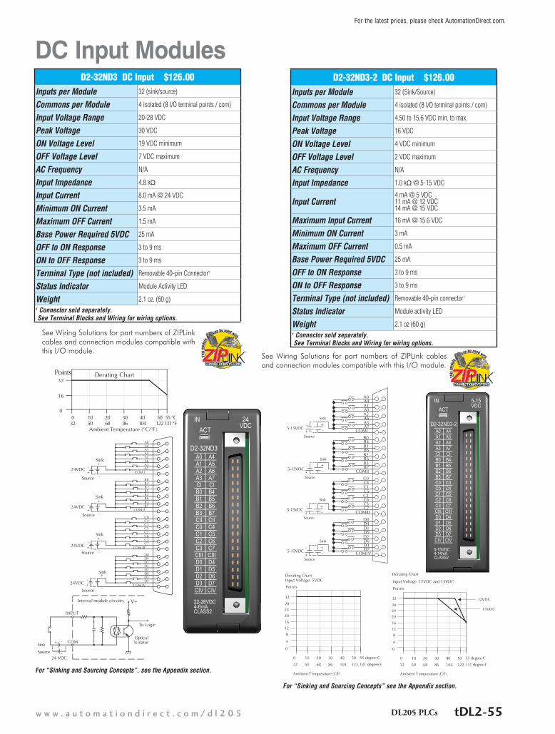
DC Input Modules D2-32ND3 DC Input $126.00
Inputs per Module 32 (sink/source)
Commons per Module 4 isolated (8 I/O terminal points / com)
Input Voltage Range 20-28 VDC
Peak Voltage 30 VDC
ON Voltage Level 19 VDC minimum
OFF Voltage Level 7 VDC maximum
AC Frequency N/A
Input Impedance 4.8 kq
Input Current 8.0 mA @ 24 VDC
Minimum ON Current 3.5 mA
Maximum OFF Current 1.5 mA
Base Power Required 5VDC 25 mA
OFF to ON Response 3 to 9 ms
ON to OFF Response 3 to 9 ms
Terminal Type (not included) Removable 40-pin Connector1
Status Indicator Module Activity LED
Weight 2.1 oz. (60 g)1 Connector sold separately. See Terminal Blocks and Wiring for wiring options.
D2-32ND3-2 DC Input $126.00Inputs per Module 32 (Sink/Source)
Commons per Module 4 isolated (8 I/O terminal points / com)
Input Voltage Range 4.50 to 15.6 VDC min. to max.
Peak Voltage 16 VDC
ON Voltage Level 4 VDC minimum
OFF Voltage Level 2 VDC maximum
AC Frequency N/A
Input Impedance 1.0 kq @ 5-15 VDC
Input Current4 mA @ 5 VDC 11 mA @ 12 VDC 14 mA @ 15 VDC
Maximum Input Current 16 mA @ 15.6 VDC
Minimum ON Current 3 mA
Maximum OFF Current 0.5 mA
Base Power Required 5VDC 25 mA
OFF to ON Response 3 to 9 ms
ON to OFF Response 3 to 9 ms
Terminal Type (not included) Removable 40-pin connector1
Status Indicator Module activity LED
Weight 2.1 oz (60 g)1 Connector sold separately. See Terminal Blocks and Wiring for wiring options.
OpticalCOM Isolator
INPUT
24 VDC
V+
To Logic
Internal module circuitry
+
A4A0
A5A1
A6A2
A7A3
COM I
B4B0
B5B1
B6B2
B7B3
COM II
C4C0
C5C1
C6C2
C7C3
COM III
D4D0
D5D1
D6D2
D7D3
COM IV
0
16
32Points
0 10 20 30 40 50 55
Ambient Temperature (°C/°F )32 50 68 86 104 122131
C°F°
Derating Chart
24VDC
+
-
+-
-
+
-
24VDC +
-
+
-
+
-
+
-
24VDC
+
-
+
-
24VDC
Sink
Source
Sink
Source
Sink
Source
Sink
Source
Sink
Source
CF
A0A1A2A3CIB0B1B2B3CIIC0C1C2C3CIIID0D1D2D3CIV
A4A5A6A7CIB4B5B6B7CIIC4C5C6C7CIIID4D5D6D7CIV
D2-32ND3
ACTIN 24
VDC
22-26VDC4-6mACLASS2
For “Sinking and Sourcing Concepts”, see the Appendix section.
For “Sinking and Sourcing Concepts” see the Appendix section.
See Wiring Solutions for part numbers of ZIPLink cables and connection modules compatible with this I/O module.
See Wiring Solutions for part numbers of ZIPLink cables and connection modules compatible with this I/O module.
tDL2-55w w w . a u t o m a t i o n d i r e c t . c o m / d l 2 0 5 DL205 PLCs
For the latest prices, please check AutomationDirect.com.

Wiring Solutions Wiring Solutions using the ZIPLink Wiring SystemZIPLinks eliminate the normally tedious process of wiring between devices by utilizing prewired cables and DIN rail mount connector modules. It’s as simple as plugging in a cable connector at either end or terminating wires at only one end. Prewired cables keep installation clean and efficient, using half the space at a fraction of the cost of standard terminal blocks. There are several wiring solutions available when using the ZIPLink System ranging from PLC I/O-to-ZIPLink Connector Modules that are ready for field termination, options for connecting to third party devices, GS, DuraPulse and SureServo Drives, as well as special relay, transorb and communications modules. Pre-printed I/O-specific adhesive label strips for quick marking of ZIPLink modules are provided with ZIPLink cables. See the following solutions to help determine the best ZIPLink system for your application.
Solution 1: Do-more, DirectLOGIC, CLICK and Productivity Series I/O Modules to ZIPLink Connector ModulesWhen looking for quick and easy I/O-to-field termination, a ZIPLink connector module used in conjunction with a prewired ZIPLink cable, consisting of an I/O terminal block at one end and a multi-pin connector at the other end, is the best solution.
Using the PLC I/O Modules to ZIPLink Connector Modules selector tables located in this section,
1. Locate your I/O module/PLC2. Select a ZIPLink Module3. Select a corresponding ZIPLink Cable.
Solution 3: GS Series and DuraPulse Drives Communication CablesNeed to communicate via Modbus RTU to a drive or a network of drives?
ZIPLink cables are available in a wide range of configurations for connecting to PLCs and SureServo, SureStep, Stellar Soft Starter and AC drives. Add a ZIPLink communications module to quickly and easily set up a multi-device network.
Using the Drives Communication selector tables located in this section,
1. Locate your Drive and type of communications 2. Select a ZIPLink cable and other associated hardware.
Solution 2: Do-more, DirectLOGIC, CLICK and Productivity Series I/O Modules to 3rd Party DevicesWhen wanting to connect I/O to another device within proximity of the I/O modules, no extra terminal blocks are necessary when using the ZIPLink Pigtail Cables. ZIPLink Pigtail Cables are prewired to an I/O terminal block with color-coded pigtail with soldered-tip wires on the other end.
Using the I/O Modules to 3rd Party Devices selector tables located in this section,
1. Locate your PLC I/O module 2. Select a ZIPLink Pigtail Cable that is compatible
with your 3rd party device.
tDL2-51w w w . a u t o m a t i o n d i r e c t . c o m / d l 2 0 5 DL205 PLCs
For the latest prices, please check AutomationDirect.com.

Wiring Solutions
Solution 4: Serial Communications CablesZIPLink offers communications cables for use with DirectLOGIC, CLICK, and Productivity CPUs, that can also be used with other communications devices. Connections include a 6-pin RJ12 or 9-pin, 15-pin and 25-pin D-sub connectors which can be used in conjunction with the RJ12 or D-Sub feedthrough modules.
Using the Serial Communications Cables selector table located in this section,
1. Locate your connector type 2. Select a cable.
Solution 5: Specialty ZIPLink ModulesFor additional application solutions, ZIPLink modules are available in a variety of configurations including stand-alone relays, 24VDC and 120VAC transorb modules, D-sub, RJ12 and RJ45 feedthrough modules, communication port adapter and distribution modules, and SureServo 50-pin I/O interface connection.
Using the ZIPLink Specialty Modules selector table located in this section,
1. Locate the type of application2. Select a ZIPLink module.
Solution 6: ZIPLink Connector Modules to 3rd Party DevicesIf you need a way to connect your device to terminal blocks without all that wiring time, then our pigtail cables with color-coded soldered-tip wires are a good solution. Used in conjunction with any compatible ZIPLink Connector Modules, a pigtail cable keeps wiring clean and easy and reduces troubleshooting time.
Using the Universal Connector Modules and Pigtail Cables table located in this section,
1. Select module type2. Select the number of pins3. Select cable.
tDL2-52 1 - 8 0 0 - 6 3 3 - 0 4 0 5DL205 PLCs
For the latest prices, please check AutomationDirect.com.

PLC I/O Modules to ZIPLink Connector Modules – Do-more!/DL205
Do-more / DL205 PLC Input Module ZIPLink SelectorPLC ZIPLinkInput
Module# of
Terms Component Module Part No.
Cable Part No. †
D2-08ND3 10 FeedthroughZL-RTB20 (-1)
ZL-D2-CBL10 *
D2-16ND3-2 19Feedthrough ZL-D2-CBL19
ZL-D2-CBL19-1 ZL-D2-CBL19-2Sensor ZL-LTB16-24-1
D2-32ND3 ¹ 40Feedthrough ZL-RTB40 (-1)
180 deg conn:ZL-D24-CBL40 ZL-D24-CBL40-1 ZL-D24-CBL40-2
45 deg conn:ZL-D24-CBL40-X ZL-D24-CBL40-1X ZL-D24-CBL40-2X
Sensor ZL-LTB32-24-1
D2-32ND3-2 ¹ 40
Feedthrough ZL-RTB40 (-1)
Sensor ZL-LTB32-24-1
D2-08NA-1 10Feedthrough
ZL-RTB20 (-1)
ZL-D2-CBL10 ZL-D2-CBL10-1 ZL-D2-CBL10-2D2-08NA-2 10
D2-16NA 19 Feedthrough ZL-D2-CBL19 *
Do-more/ DL205 PLC Output Module ZIPLink SelectorPLC ZIPLink
Output Module
# of Terms Component Module Part No. Cable Part
No. †D2-04TD1 ²
10 FeedthroughZL-RTB20 (-1)
ZL-D2-CBL10 ZL-D2-CBL10-1 ZL-D2-CBL10-2
D2-08TD1D2-08TD2
D2-16TD1-2
19
Feedthrough
ZL-D2-CBL19 ZL-D2-CBL19-1 ZL-D2-CBL19-2
Fuse ZL-RFU20 4
D2-16TD2-2
Feedthrough ZL-RTB20 (-1)
Fuse ZL-RFU20 4
RelayZL-RRL16-24-2
ZL-RRL16W-24-2 ZL-RRL16F-24-2
ZL-RRL16HDF-24-2
F2-16TD1PFeedthrough ZL-RTB20 (-1)
F2-16TD2P
D2-32TD1 ¹
40
Feedthrough ZL-RTB40 (-1) 180 deg conn:ZL-D24-CBL40 ZL-D24-CBL40-1 ZL-D24-CBL40-2
45 deg conn:ZL-D24-CBL40-X ZL-D24-CBL40-1X ZL-D24-CBL40-2X
Fuse ZL-RFU40 4
D2-32TD2 ¹Feedthrough ZL-RTB40 (-1)
Fuse ZL-RFU40 4
D2-08TA10 Feedthrough
ZL-RTB20 (-1)
ZL-D2-CBL10 ZL-D2-CBL10-1 ZL-D2-CBL10-2F2-08TA
D2-12TA 19Feedthrough ZL-D2-CBL19
ZL-D2-CBL19-1 ZL-D2-CBL19-2Fuse ZL-RFU20 4
D2-04TRS 210 Feedthrough
ZL-RTB20 (-1)
ZL-D2-CBL10 ZL-D2-CBL10-1 ZL-D2-CBL10-2D2-08TR
F2-08TRS 2 19Feedthrough
ZL-D2-CBL19 *F2-08TR 3 10 ZL-D2-CBL10 *
D2-12TR 19Feedthrough ZL-D2-CBL19
ZL-D2-CBL19-1 ZL-D2-CBL19-2Fuse ZL-RFU20 4
† X in the part number represents a 45° angle plug
* Select the cable length by replacing the * with: Blank = 0.5 m, -1 = 1.0 m, or -2 = 2.0 m.
1 To make a custom cable for the 32-point modules, use: Ribbon-style Connector ZL-D24-CON-R, Solder-style 180° connector ZL-D24-CON or Solder-style 45° connector ZL-D24-CON-X
2 Caution: The D2-04TD1, D2-04TRS, and F2-08TRS outputs are derated not to exceed module specs 2A per point and 2A per common when used with the ZIPLink wiring system.
3 The F2-08TR outputs are derated not to exceed 2A per point and 4A per common when used with the ZIPLink wiring system.
4 Fuses (5 x 20 mm) are not included. See Edison Electronic Fuse section for (5 x 20 mm) fuse. S500 and GMA electronic circuit protection for fast-acting maximum protection. S506 and GMC electronic circuit protection for time-delay performance. Ideal for inductive circuits. To ensure proper operation, do not exceed the voltage and current rating of ZIPLink module. ZL-RFU20 = 2A per circuit; ZL-RFU40 = 400mA per circuit.
Do-more/DL205 PLC Combo In/Out Module ZIPLink SelectorPLC ZIPLink
Combo Module
# of Terms Component Module Part
No. Cable Part No.
D2-08CDR 10 Feedthrough ZL-RTB20 (-1) ZL-D2-CBL10 *
Do-more/DL205 PLC Analog Module ZIPLink SelectorPLC ZIPLink
Analog Module
# of Terms Component Module Cable
F2-04AD-1
10
Feedthrough ZL-RTB20 (-1)
ZL-D2-CBL10 ZL-D2-CBL10-1 ZL-D2-CBL10-2
F2-04AD-1LF2-08AD-1F2-04AD-2F2-04AD-2LF2-08AD-2F2-02DA-1F2-02DA-1LF2-02DAS-1
F2-08DA-1 ZL-D2-CBL19 ZL-D2-CBL19-1 ZL-D2-CBL19-2F2-02DA-2
F2-02DA-2LZL-D2-CBL10 ZL-D2-CBL10-1 ZL-D2-CBL10-2
F2-02DAS-2F2-08DA-2F2-4AD2DA
F2-8AD4DA-119
ZL-D2-CBL19 ZL-D2-CBL19-1 ZL-D2-CBL19-2F2-8AD4DA-2
F2-04RTD Matched Only
These modules are not supported by the ZIPLink wiring systemF2-04THM
Note: ZIPLINk CoNNeCtoR ModuLe sPeCIfICatIoNs foL-LoW the CoMPatIbILIty MatRIx tabLes. ZIPLINk CabLes sPeCIfICatIoNs aRe at the eNd of thIs ZIPLINk seCtIoN.
† X in the part number represents a 45° angle.
tDL2-53w w w . a u t o m a t i o n d i r e c t . c o m / d l 2 0 5 DL205 PLCs
For the latest prices, please check AutomationDirect.com.

These charts help determine your power requirementsThis section shows the amount of power supplied by each of the base power supplies and the amount of power consumed by each DL205 device. The Power Consumed charts list how much INTERNAL power from each power source is required for the DL205 devices. Use this information when calculating the power budget for your system.
In addition to the internal power sources, the DL205 bases offer a 24 VDC auxiliary power supply with external power connec-tions. This auxiliary power supply can power external devices.
Use ZIPLinks to reduce power requirementsIf your application requires a lot of relay outputs, consider using the ZIPLink AC or DC relay output modules. These modules can switch high current (10A) loads without putting a load on your base power budget. Refer to the Terminal Blocks and Wiring Solutions section in this catalog for more information.
This logo is placed next to the I/O modules that are supported by the ZIPLink connection systems. See the I/O module specifications at the end of this section.
Power RequirementsHERE
Power SuppliedDevice Price 5V(mA) 24V Auxiliary Device Price 5V(mA) 24V AuxiliaryBases BasesD2-03B-1 $132.00 2600 300 D2-06BDC1-1 $194.00 2600 None
D2-03BDC1-1 $150.00 2600 None D2-06BDC2-1 $184.00 2600 300
D2-04B-1 $143.00 2600 300 D2-09B-1 $220.00 2600 300
D2-04BDC1-1 $171.00 2600 None D2-09BDC1-1 $238.00 2600 None
D2-06B-1 $176.00 2600 300 D2-09BDC2-1 $238.00 2600 300
Power ConsumedDevice 5V(mA) 24V AuxiliaryCPUsD2-250-1 330 0
D2-260 330 0
H2-WPLC*-** 680 0
DC Input ModulesD2-08ND3 50 0
D2-16ND3-2 100 0
D2-32ND3 25 0
D2-32ND3-2 25 0
AC Input ModulesD2-08NA-1 50 0
D2-08NA-2 100 0
D2-16NA 100 0
Input Simulator ModuleF2-08SIM 50 0
DC Output ModulesD2-04TD1 60 20
D2-08TD1 100 0
D2-08TD2 100 0
D2-16TD1-2 200 80
D2-16TD2-2 200 0
F2-16TD1P 70 50
F2-16TD2P 70 50
D2-32TD1 350 0
D2-32TD2 350 0
AC Output ModulesD2-08TA 250 0
F2-08TA 250 0
D2-12TA 350 0
Relay Output ModulesD2-04TRS 250 0
D2-08TR 250 0
F2-08TR(S) 670 0
D2-12TR 450 0
Combination In/Out ModuleD2-08CDR 200 0
Power ConsumedDevice 5V(mA) 24V AuxiliaryAnalog ModulesF2-04AD-1 100 5
F2-04AD-2 110 5
F2-08AD-1 100 5
F2-08AD-2 100 5
F2-02DA-1 40 60 (note 1)
F2-02DA-1L 40 70 @ 12V (note 1)
F2-02DA-2 40 60
F2-02DA-2L 40 70 @ 12V
F2-02DAS-1F2-02DAS-2
100100
50 / channel60 / channel
F2-08DA-1 30 50 (note 1)
F2-08DA-2 60 140
F2-4AD2DA 60 80 (note 1)
F2-8AD4DA-1 35 100 (note 1)
F2-8AD4DA-2 35 80 (note 1)
F2-04RTD 90 0
F2-04THM 110 60
Specialty ModulesD2-CTRINT 50* 0
D2-CM / D2-EM 100/130 0
H2-CTRIO2 275 0
D2-DCM 300 0
F2-DEVNETS 160 0
F2-SDS-1 160 0
H2-EBC100 300 0
H2-EBC-F 640 0
H2-ECOM100 300 0
H2-ECOM-F 640 0
F2-CP128 235 0
Remote I/OH2-ERM100, (-F) 300, (-F: 450) 0
Programming DevicesD2-HPP 200 0*requires external 5VDC for outputsNote 1: Add an additional 20 mA per output loop.
Power ConsumedDevice 5V(mA) 24V Auxiliary
Operator InterfaceDV-1000 150 0
C-more Micro-Graphic 210 0
tDL2-24 1 - 8 0 0 - 6 3 3 - 0 4 0 5DL205 PLCs
For the latest prices, please check AutomationDirect.com.