ford 2011-2013 coyote 5.0l crate engine supported …aemelectronics.com/files/instructions/infinity...
TRANSCRIPT

Infinity Supported ApplicationFord Coyote 5.0L
With Ford Racing Controls Pack
AEM Performance ElectronicsAEM Performance Electronics, 2205 126th Street Unit A, Hawthorne, CA 90250
Phone: (310) 484-2322 Fax: (310) 484-0152http://www.aemelectronics.com
Instruction Part Number: Document Build 1/6/2015
InstructionManual
STOP!
THIS PRODUCT HAS LEGAL RESTRICTIONS. READ THIS BEFORE INSTALLING/USING!
THIS PRODUCT MAY BE USED SOLELY ON VEHICLES USED IN SANCTIONED COMPETITION WHICH MAY NEVER BE USED UPON A
PUBLIC ROAD OR HIGHWAY, UNLESS PERMITTED BY SPECIFIC REGULATORY EXEMPTION. (VISIT THE “EMISSIONS” PAGE AT HTTP://
WWW.SEMASAN.COM/EMISSIONS FOR STATE BY STATE DETAILS.)
IT IS THE RESPONSIBILITY OF THE INSTALLER AND/OR USER OF THIS PRODUCT TO ENSURE THAT IT IS USED IN COMPLIANCE WITH
ALL APPLICABLE LAWS AND REGULATIONS. IF THIS PRODUCT WAS PURCHASED IN ERROR, DO NOT INSTALL AND/OR USE IT. THE
PURCHASER MUST ARRANGE TO RETURN THE PRODUCT FOR A FULL REFUND.
THIS POLICY ONLY APPLIES TO INSTALLERS AND/OR USERS WHO ARE LOCATED IN THE UNITED STATES; HOWEVER CUSTOMERS
WHO RESIDE IN OTHER COUNTRIES SHOULD ACT IN ACCORDANCE WITH THEIR LOCAL LAWS AND REGULATIONS.
WARNING: This installation is not for the tuning novice! Use this system with EXTREME caution! The AEMInfinity Programmable EMS allows for total flexibility in engine tuning. Misuse or improper tuning of thisproduct can destroy your engine! If you are not well versed in engine dynamics and the tuning of enginemanagement systems DO NOT attempt the installation. Refer the installation to an AEM-trained tuningshop or call 800-423-0046 for technical assistance.
NOTE: All supplied AEM calibrations, Wizards and other tuning information are offered as potentialstarting points only. IT IS THE RESPONSIBILITY OF THE ENGINE TUNER TO ULTIMATELY CONFIRM IF THECALIBRATION IS SAFE FOR ITS INTENDED USE. AEM holds no responsibility for any engine damage thatresults from the misuse or mistuning of this product!

2
© 2015 AEM Performance Electronics
OVERVIEWThis document is intended to serve as a guide to help with the installation and setup of an AEM InfinityEMS onto a Ford Coyote 5.0L Crate Engine interfaced through the Ford Racing Controls Pack – 5.0L 4VTI-VCT Manual Transmission. These sessions and configuration files are starting points only and willneed to be tuned for your specific application. This manual lists the files available and suggestedchanges for your engine. This manual also includes a pinout with suggestions for adapting the InfinityECU to your Ford Racing Controls Pack. It is the responsibility of the installer to verify this informationbefore starting the engine. Please read this document in its entirety before attempting to start orrun an engine.
MODELSFord Racing 5.0L 4V TI-VCT Mustang Crate Engine Ford Racing P/N M-6007-M50Ford Racing Controls Pack – 5.0L 4V TI-VCT Manual Transmission Ford Racing P/N M-6017-A504V
DOWNLOADABLE FILESFiles can be downloaded from www.aeminfinity.com. An experienced tuner must be available to configureand manipulate the data before driving can commence. The Quick Start Guide and Full Manual describethe steps for logging in and registering at www.aeminfinity.com. These documents are available fordownload in the Support section of the AEM Electronics website: http://www.aemelectronics.com/products/support/instructions.

Infinity Supported Application 3
© 2015 AEM Performance Electronics
ADAPTER HARNESS OPTIONS30-3701 Plug & Pin KitThis kit includes mating connectors and terminals for the Infinity. It also includes a main relay kit whichis necessary for proper power distribution. This kit is best suited for experienced installers who want tobuild their own harness.
30-3702 Harness with Flying LeadsThis harness includes a fused power distribution center with main relay. Pre-terminated connectors areavailable for the internal UEGO sensors and AEMNet. A bag of multi-color flying leads is included tosimplify custom harness builds.
30-3703 Mini Harness with PinsThis harness includes a fused power distribution center with main relay. Pre-terminated connectors areavailable for the internal UEGO sensors and AEMNet. 100 pins and 30 sealing plugs are included.
30-2001 UEGO Wideband O2 SensorBosch LSU4.2 Wideband O2 Sensor that connects to AEM 30-3600 UEGO Wideband O2 SensorExtension Harness
30-3600 UEGO Wideband O2 Sensor Extension HarnessExtension harness to connect AEM UEGO Wideband O2 sensor to 6-pin Deutsch
30-3601 IP67 Comms CableUSB Mini-B comms cable; 39” long with right angled connector and bayonet style lock.
30-3602 IP67 Logging CableUSB A-to-A extension cable: 39” long with right angled connector and bayonet style lock.

4
© 2015 AEM Performance Electronics
IMPORTANT APPLICATION NOTESThe coils used for testing were factory two-wire ignition coils (Motorcraft P/N BR3Z-12029-A). Forcompatibility with the Infinity EMS the use of an igniter that accepts a Falling edge fire signal isnecessary. For application development two AEM 4 Channel Coil Drivers (AEM P/N 30-2840) were used.
The Ford Racing Controls Pack wiring harness includes connectors for factory LSU4.9 WidebandOxygen sensors (Motorcraft P/N XXXX), which the Infinity EMS does not currently support. Duringapplication development the factory LSU4.9 sensor connectors were removed and AEM WidebandUEGO sensor connectors were added to the Ford Racing wiring harness. These UEGO sensorconnectors are included in the AEM Universal EMS Wideband UEGO Sensor Kit (P/N 30-2002) andinformation regarding how to wire the connector is provided under UEGO Connectors in this document.Using the existing wiring harness comes with the benefit of utilizing the existing 12V supply to thesensor through a 5 amp fuse. Another option available to the installer is the use of AEM Infinity O2Sensor Extension Harnesses (AEM P/N 30-3600). This option involves wiring a 6-pin Deutsch connectorto the Infinity EMS to interface with the AEM O2 sensor through the extension harness without anymodification to the Ford Racing wiring harness.
The Ford Racing Controls Pack includes a Power Distribution Box containing relays for A/C, PCM,Intercooler, Fuel Pump, Start, and Fan. With a few modifications to the harness, the Infinity will utilize allof these relays with the exception of the A/C relay due to Ford Racing's lack of wiring to the A/C relay.
The base session provided was created with the use of the Ford Racing Mustang Boss 302 Alternator Kit(P/N M-8600-M50BALT). The session has Lowside 0 Duty and frequency tables setup to charge at ~14.7volts. See Alternator Control in this document for more information on controlling the charging system.
The base session provided was created without the use of the Ford Racing Controls Pack air box, inlettube, or MAF sensor. The Factory MAF sensor is not currently supported by the Infinity EMS for airflowcalculations; however the Air Temperature sensor within the MAF has been characterized.
The base session requires a MAP sensor for airflow calculations. A custom inlet was fabricated toreplace the PCV inlet pipe into the passenger side of the throttle body assembly. A vacuum line from thisinlet to a MAP sensor was utilized.
The Ford Racing Control Pack powers the fuel pump relay any time 12V is supplied to the ‘IgnitionSwitch Position’ wire. A modification can be made to the Ford Racing wiring harness to allow the InfinityEMS to control the fuel pump and is provided under Ford Racing Control Pack Harness Modifications inthis document.
The base session utilizes the Clutch Position (Neutral Switch) flying lead on the Ford Racing wiringharness as an input into the Infinity. Once triggered, the Infinity’s Lowside provides the ground for theStarter Relay control circuit. If the user wishes not to provide a ground to this flying lead follow the stepsprovided under Clutch Position Switch in this document to modify the Lowside.
The factory Cylinder Head Temperature sensor, Intake Air Temperature sensor, and fuel injector havebeen fully characterized and their calibrations are utilized in the base session.

Infinity Supported Application 5
© 2015 AEM Performance Electronics
GETTING STARTEDRefer to the 10-7100 for EMS 30-7100 Infinity Quick Start Guide for additional information on gettingthe engine started with the Infinity EMS.
LOADING BASE SESSION
1. Connect USB comms cable between ECU and PC.
2. Turn ignition switch on.
3. Open InfinityTuner; connection status should be green and indicate ECU type.
4. Import base session: File>Import Calibration Data. Base sessions are located in C:\Documents\AEM\Infinity Tuner\Sessions\Base Sessions.
5. After comms have been reestablished, review Setup Wizard: Wizards>Setup Wizard.
INFINITY CONNECTORSThe AEM Infinity EMS uses the MX123 SealedConnection System from Molex. AEM stronglyrecommends that users become familiar with theproper tools and procedures for working with thesehigh density connectors before attempting anymodifications. The entire Molex MX123 UserManual can be downloaded direct from Molex at:
http://www.molex.com/mx_upload/family//MX123UserManual.pdf

6
© 2015 AEM Performance Electronics
IMPORTANT APPLICATION SPECIFIC SETTINGS
Infinity Tuner Wizard Setup
Alternator Control
The Ford Mustang Boss 302 Alternator is controlled by a fixed frequency and a duty percentage thatcontrols the charge set point.
The base session sets LS0_Duty to 35 % which correlates to ~14.7V charge. Decreasing the LS0_Dutypercentage will increase the battery set point (higher voltage), and increasing the duty percentage willdecrease the battery set point (lower voltage).

Infinity Supported Application 7
© 2015 AEM Performance Electronics
Clutch Position Switch
The base session will not provide a ground for the Starter Relay control circuit unless a ground isprovided to the Clutch Position (Neutral Switch) flying lead on the Ford Racing wiring harness. Thisrequirement can be modified through setting the LS8_Duty [%] table to 100% at all ClutchSwitchpositions. See example below:
The base session sets the input for the ‘ClutchSwitch’ 1D table channel to Analog20, which is pulled upto 5 volts. The pinout provided in this manual suggests wiring the Clutch Position flying lead to Analog20.When a ground is provided this drops Analog20’s voltage from 5 volts to 0 volts, this transition in voltagesets the ClutchSwitch channel to 0 (5 volts) or 1 (0 volts).
Note: It has been observed that EngineSpeed [RPM] will jump to ~1450 rpm at first crank of the engine.Setting the point at which Lowside 8 will no longer provide a ground (0% duty) to the Starter Relaycontrol circuit below 1500 rpm may result in a no-start condition.
Drive-By-Wire
The base calibration will set most of the Drive-By-Wire (DBW) channels for the stock 5.0L Coyote throttlebody. If a different throttle body is used, Supra Cobra or Cobra Jet, then further adjustments to the DBWchannels may be required. To complete the DBW setup the Drive By Wire Wizard must be ran.
Select Calibrate sensor data only and follow the DBW Setup steps.
Note: There are a few integrated DBW fail safes incorporated into the Infinity system. For instance, if theaccelerator pedal and throttle position sensors do not track each other, or if the maximum DBW currentis exceeded, there will be a fatal error which will kill the engine for safety purposes. This error will resetwhen the ignition key is cycled or if the problem is fixed.

8
© 2015 AEM Performance Electronics
Variable Valve Control (VVC)
The AEM Infinity system supports Fords Coyote’s Variable Valve Control. The base calibration isconfigured with base VVC settings that may need adjustment.
For proper VVC function, the user must sync the cam timing by following the instructions listed in SetupWizard: Wizards>Setup Wizard>VVC>VVC Cam Sync.
VVC to Cam correlation is as follows:
Cam 0 = VVC2A – CMP 12Cam 1 = VVC2B – CMP 22Cam 2 = VVC1A – CMP 11Cam 3 = VVC1B – CMP 21
FORD RACING CONTROL PACK HARNESS MODIFICATIONS(OPTIONAL)
Fuel Pump Flying Lead
To allow the Infinity to control the fuel pump a modification must be made to the C47 flying leadconnector.
The Green w/ Black stripe wire is the Highside Fuel Pump relay control wire (C47-01). The Ford Racingharness double crimps 12V Start & Run (C47-03 ISP-R) to this fuel pump highside so that the fuel pumpis running when the key is on.

Infinity Supported Application 9
© 2015 AEM Performance Electronics
The Green w/ Black stripe wire needs to be cut off of this double crimp.
Reinstall the Green w/ Black stripe wire’s pre-existing pin back into the C47-01 socket. Route a wire thatconnects the Green w/ Black stripe wire to the Infinity’s C2-55 pin.

10
© 2015 AEM Performance Electronics
UEGO Connectors
Currently the Infinity does not support the stock Ford Coyote Bosch LSU4.9 UEGO sensors, andinstallation of LSU4.2 UEGO sensors is required.
During Infinity application development the existing LSU4.9 connectors on the Ford Racing wiringharness were removed and re-terminated into LSU4.2 connectors. Provided in the AEM 30-2002Universal EMS Wideband UEGO Sensor kit is the necessary LSU4.2 connector and pins.
Below is the comparison of the Ford Racing wiring harness LSU4.9 connector and the AEM LSU4.2connector according to the Ford Racing Control Pack Installation Manual (2011 and new 5.0L 4V). Note:“Ford Color” callouts listed in the Ford Racing Installation Manual may not align with actual wire colors.The “Ford Color” callouts below are representative of actual wire colors found on the Ford Racing harnessat the time of Infinity application development:

Infinity Supported Application 11
© 2015 AEM Performance Electronics
PINOUTS
Ford Coyote 5.0L With Ford Racing Control Pack Pinout
FordEngine
PinWire Color
Ford Coyotewith FR
Control PackDescription
InfinityPin
InfinityAssignment
Infinity HardwareSpecification
Notes
E-01 --- --- --- Not used --- Not used Not used Not used
E-02 Violet
Variable
Camshaf t
Timing 11
Solenoid
(Passengerside
Intake)
C1-18 LowsideSwitch_3
Lowside switch, 4A
max with internal
f ly back diode.
Inductiv e load should
NOT hav e f ull time
power.
See Setup Wizard
Page ‘LowSide
Assignment Tables’
f or conf iguration
options. See 2D table
‘LS3_Duty [%]’ f or
activ ation settings.
See Setup Wizard
page 'VVC' f or
options.
E-03 --- --- --- Not used --- Not used Not used Not used
E-04 --- --- --- Not used --- Not used Not used Not used
E-05 --- --- --- Not used --- Not used Not used Not used
E-06* White/Brown
Knock Sensor 1
& 2 Ground
[KS1 - & KS2 -]
– Shared with
E-44
C2-31 AGND_2Dedicated analog
ground
Analog 0–5V sensor
ground
E-07 Violet/Orange
Knock Sensor +
[KS1+]C1-27 Knock Sensor 1
Dedicated knock
signal processor
See Setup Wizard
page 'Knock Setup'
f or options.
E-08 Blue/Orange DBW Ground
(ETCRTN)C2-30 AGND_2
Dedicated analog
ground
Analog 0–5V sensor
ground
E-09 Yellow
'Electronic
Throttle Control
(ETCREF)
C1-41 +5V_Out_1Regulated, f used +5V
supply f or sensor
power
Analog sensor power
E-10 Green/Violet
Throttle
Position #
Positiv e Slope
(TP2)
C2-21 Analog_In_1612 bit A/D, 100K
pullup to 5V
0–5V analog signal.
Use +5V Out pins as
power supply and
Sensor Ground pins
as the low ref erence.
Do not connect
signals ref erenced to
+12V as this can
permanently damage
the ECU.
E-11 Black
Crankshaf t
Position Sensor
Shield
(SHDRTN)
C1-30 Power Ground Power GroundConnect directly to
battery ground.
E-12 Green/Brown
Crankshaf t
Position Sensor
(CKP-)
C1-46Crankshaf t Position
Sensor VR-

12
© 2015 AEM Performance Electronics
FordEngine
PinWire Color
Ford Coyotewith FR
Control PackDescription
InfinityPin
InfinityAssignment
Infinity HardwareSpecification
Notes
E-13 Yellow/Violet
Crankshaf t
Position (CKP+)C1-45
Crankshaf t Position
Sensor VR+
Dif f erential Variable
Reluctance Zero
Cross Detection
See Setup Wizard
page 'Cam/Crank' f or
options.
E-14 --- --- --- Not used --- Not used Not used Not used
E-15 --- --- --- Not used --- Not used Not used Not used
E-16 Yellow/Grey
Variable
Camshaf t
Timing 21
Solenoid
(Driv erside
Intake)
C1-2 LowsideSwitch_5
Lowside switch, 4A
max with internal
f ly back diode.
Inductiv e load should
NOT hav e f ull time
power.
See Setup Wizard
Page ‘LowSide
Assignment Tables’
f or conf iguration
options. See 2D table
‘LS5_Duty [%]’ f or
activ ation settings.
See Setup Wizard
page 'VVC' f or
options.
E-17 --- --- --- Not used --- Not used Not used Not used
E-18 Blue/Orange
Coil on Plug
Assembly 3
(COP3F)
C1-12 Coil 325 mA max source
current
0–5V Falling edge
f ire. DO NOT
connect directly to
coil primary . Must
use an ignitor OR
CDI that accepts a
FALLING edge f ire
signal.
E-19 --- --- --- Not used --- Not used Not used Not used
E-20 --- --- --- Not used --- Not used Not used Not used
E-21 --- --- --- Not used --- Not used Not used Not used
E-22 --- --- --- Not used --- Not used Not used Not used
E-23 --- --- --- Not used --- Not used Not used Not used
E-24 --- --- --- Not used --- Not used Not used Not used
E-25 --- --- --- Not used --- Not used Not used Not used
E-26 --- --- --- Not used --- Not used Not used Not used
E-27 --- --- --- Not used --- Not used Not used Not used
E-28 --- --- --- Not used --- Not used Not used Not used
E-29 Grey /Orange
VR Reluctance
Sensor
(VRSRTN)
C1-47Camshaf t Position
Sensor 1 VR-
Dif f erential Variable
Reluctance Zero
Cross Detection
See Setup Wizard
page 'Cam/Crank' f or
options.
E-30 Blue/Grey
Cy linder Head
Temperature
(CHT)
C1-66 Analog_In_Temp_112 bit A/D, 2.49K
pullup to 5V
See 'Coolant
Temperature' Setup
Wizard f or selection.
E-31 --- --- --- Not used --- Not used Not used Not used

Infinity Supported Application 13
© 2015 AEM Performance Electronics
FordEngine
PinWire Color
Ford Coyotewith FR
Control PackDescription
InfinityPin
InfinityAssignment
Infinity HardwareSpecification
Notes
E-32 Green/White
Digital Cams
Ground (E-
SIGRTN)
C1-20 AGND_1Dedicated analog
ground
Analog 0–5V sensor
ground
E-33 Yellow/Grey
Coil on Plug
Assembly 7
(COP7G)
C2-51 Coil 725 mA max source
current
0–5V Falling edge
f ire. DO NOT
connect directly to
coil primary . Must
use an ignitor OR
CDI that accepts a
FALLING edge f ire
signal.
E-34 White/Brown
Coil on Plug
Assembly 5
(COP5B)
C1-16 Coil 525 mA max source
current
0–5V Falling edge
f ire. DO NOT
connect directly to
coil primary . Must
use an ignitor OR
CDI that accepts a
FALLING edge f ire
signal.
E-35 --- --- --- Not used --- Not used Not used Not used
E-36* Violet/Green
Injector and
Digital Cam
Sensor +12V
Power – Shared
with PCM70-21
C1-61 +12V12 v olt power f rom
relay
12 v olt power f rom
relay . Relay must be
controlled by +12V
Relay Control signal,
pin C1-29 abov e.
E-37 --- --- --- Not used --- Not used Not used Not used
E-38 --- --- --- Not used --- Not used Not used Not used
E-39 Brown
DBW Negativ e
Slope (TP1)C1-35 Analog_In_7
12 bit A/D, 100K
pullup to 5V
0–5V analog signal.
Use +5V Out pins as
power supply and
Sensor Ground pins
as the low ref erence.
Do not connect
signals ref erenced to
+12V as this can
permanently damage
the ECU. See the
Setup Wizard Set
Throttle Range page
f or automatic min/
max calibration.
Monitor the Throttle
[%] channel. Also
DB1_TPSA [%] f or
DBW applications.
E-40 --- --- --- Not used --- Not used Not used Not used
E-41 White/Green
Camshaf t
Position Bank 1
(Passenger
Intake)
(CMP11)
C1-22Camshaf t Position
Sensor 1 Hall
10K pullup to 12V.
Will work with ground
or f loating switches.
See Setup Wizard
page 'Cam/Crank' f or
options.

14
© 2015 AEM Performance Electronics
FordEngine
PinWire Color
Ford Coyotewith FR
Control PackDescription
InfinityPin
InfinityAssignment
Infinity HardwareSpecification
Notes
E-42 Yellow/Blue
Camshaf t
Position Bank 2
(Driv erside
Intake)
(CMP21)
C1-23 Digital_In_2
10K pullup to 12V.
Will work with ground
or f loating switches.
See Setup Wizard
page 'Cam/Crank' f or
options.
E-43 --- --- --- Not used --- Not used Not used Not used
E-44* Brown/Green
Knock Sensor 1
& 2 Ground
[KS1 - & KS2 -]
- Shared with E-
6
C2-31 AGND_2Dedicated analog
ground
Analog 0–5V sensor
ground
E-45 Brown/Blue
Knock Sensor+
[KS2+]C1-28 Knock Sensor 2
Dedicated knock
signal processor
See Setup Wizard
page 'Knock Setup'
f or options.
E-46 Brown/Blue
Camshaf t
Position Bank 1
In
(Passengerside
Exhaust)
(CMP12)
C1-48Camshaf t Position
Sensor 1 VR+
Dif f erential Variable
Reluctance Zero
Cross Detection
See Setup Wizard
page 'Cam/Crank' f or
options.
E-47 Green/Violet
Camshaf t
Position Bank 2
In (Driv erside
Exhaust)
(CMP22)
C1-49 VR+_In_2
E-48 Grey /Orange
Variable
Reluctance
Sensor
(VRSRTN2)
C1-50 VR-_In_2
E-49 --- --- --- Not used --- Not used Not used Not used
E-50 Green/Violet
Coil on Plug
Assembly 4
(COP4C)
C1-11 Coil 425 mA max source
current
0–5V Falling edge
f ire. DO NOT
connect directly to
coil primary . Must
use an ignitor OR
CDI that accepts a
FALLING edge f ire
signal.
E-51 Blue/Brown
Coil on Plug
Assembly 8
(COP8D)
C2-52 Coil 825 mA max source
current
0–5V Falling edge
f ire. DO NOT
connect directly to
coil primary . Must
use an ignitor OR
CDI that accepts a
FALLING edge f ire
signal.

Infinity Supported Application 15
© 2015 AEM Performance Electronics
FordEngine
PinWire Color
Ford Coyotewith FR
Control PackDescription
InfinityPin
InfinityAssignment
Infinity HardwareSpecification
Notes
E-52 Yellow/Blue
Coil on Plug
Assembly 2
(COP2H)
C1-13 Coil 225 mA max source
current
0–5V Falling edge
f ire. DO NOT
connect directly to
coil primary . Must
use an ignitor OR
CDI that accepts a
FALLING edge f ire
signal.
E-53 Green/Blue
Fuel Injector
Driv er 1 (INJ1)C1-63 Injector 1
Saturated or peak
and hold, 3A max
continuous
Injector 1
E-54 Grey /Yellow
Fuel Injector
Driv er 2 (INJ2)C1-62 Injector 2
Saturated or peak
and hold, 3A max
continuous
Injector 2
E-55 Violet/Grey
Fuel Injector
Driv er 3 (INJ3)C1-59 Injector 3
Saturated or peak
and hold, 3A max
continuous
Injector 3
E-56 White/Orange
Variable
Camshaf t
Timing 12
Solenoid
(Passengerside
Exhaust)
C1-3 LowsideSwitch_6
Lowside switch, 4A
max with internal
f ly back diode.
Inductiv e load should
NOT hav e f ull time
power.
See Setup Wizard
Page ‘LowSide
Assignment Tables’
f or conf iguration
options. See 2D table
‘LS6_Duty [%]’ f or
activ ation settings.
See Setup Wizard
page 'VVC' f or
options.
E-57 Brown/Violet
Variable
Camshaf t
Timing 22
Solenoid
(Driv erside
Exhaust)
C2-44 LowsideSwitch_7
Lowside switch, 4A
max with internal
f ly back diode.
Inductiv e load should
NOT hav e f ull time
power.
See Setup Wizard
Page ‘LowSide
Assignment Tables’
f or conf iguration
options. See 2D table
‘LS7_Duty [%]’ f or
activ ation settings.
See Setup Wizard
page 'VVC' f or
options.
E-58 --- --- --- Not used --- Not used Not used Not used
E-59 --- --- --- Not used --- Not used Not used Not used
E-60 --- --- --- Not used --- Not used Not used Not used
E-61 --- --- --- Not used --- Not used Not used Not used
E-62 Yellow/Orange
Fuel Injector
Driv er 4 (INJ4)C1-58 Injector 4
Saturated or peak
and hold, 3A max
continuous
Injector 4
E-63 Brown
Fuel Injector
Driv er 5 (INJ5)C1-57 Injector 5
Saturated or peak
and hold, 3A max
continuous
Injector 5
E-64 Green/White
Fuel Injector
Driv er 6 (INJ6)C1-56 Injector 6
Saturated or peak
and hold, 3A max
continuous
Injector 6

16
© 2015 AEM Performance Electronics
FordEngine
PinWire Color
Ford Coyotewith FR
Control PackDescription
InfinityPin
InfinityAssignment
Infinity HardwareSpecification
Notes
E-65 Grey /Brown
Fuel Injector
Driv er 7 (INJ7)C2-4 Injector 7
Saturated or peak
and hold, 3A max
continuous
Injector 7
E-66 Violet/Orange
Fuel Injector
Driv er 8 (INJ8)C2-5 Injector 8
Saturated or peak
and hold, 3A max
continuous
Injector 8
E-67 Blue/Green
Throttle
Actuator
Control Motor
(TACM-)
C1-53 DBW1 Motor -5.0A max Throttle
Control Hbridge Driv e+12V to close
E-68 Yellow/Violet
Throttle
Actuator
Control
Motor(TACM+)
C1-54 DBW1 Motor +5.0A max Throttle
Control Hbridge Driv e+12V to open
E-69 Violet/Brown
Coil on Plug
Assembly 6
(COP6E)
C1-15 Coil 625 mA max source
current
0–5V Falling edge
f ire. DO NOT
connect directly to
coil primary . Must
use an ignitor OR
CDI that accepts a
FALLING edge f ire
signal.
E-70 White/Violet
Coil on Plug
Assembly 1
(COP1A)
C1-14 Coil 125 mA max source
current
0–5V Falling edge
f ire. DO NOT
connect directly to
coil primary . Must
use an ignitor OR
CDI that accepts a
FALLING edge f ire
signal.
* Denotes shared Infinity Pin Location
FordRacingPCM70
Pin
Wire Color
Ford Coyotewith FR
Control PackDescription
InfinityPin
InfinityAssignment
Infinity HardwareSpecification
Notes
PCM70-01 --- --- --- Not used --- Not used Not used Not used
PCM70-02 Light Blue/Red IAT Sensor
GroundC1-19 AGND_1
Dedicated analog
ground
Analog 0–5V sensor
ground
PCM70-03 --- --- --- Not used --- Not used Not used Not used
PCM70-04 --- --- --- Not used --- Not used Not used Not used
PCM70-05 --- --- --- Not used --- Not used Not used Not used
PCM70-06 --- --- --- Not used --- Not used Not used Not used
Infinity Supported Application 17
© 2015 AEM Performance Electronics
FordRacingPCM70
Pin
Wire Color
Ford Coyotewith FR
Control PackDescription
InfinityPin
InfinityAssignment
Infinity HardwareSpecification
Notes
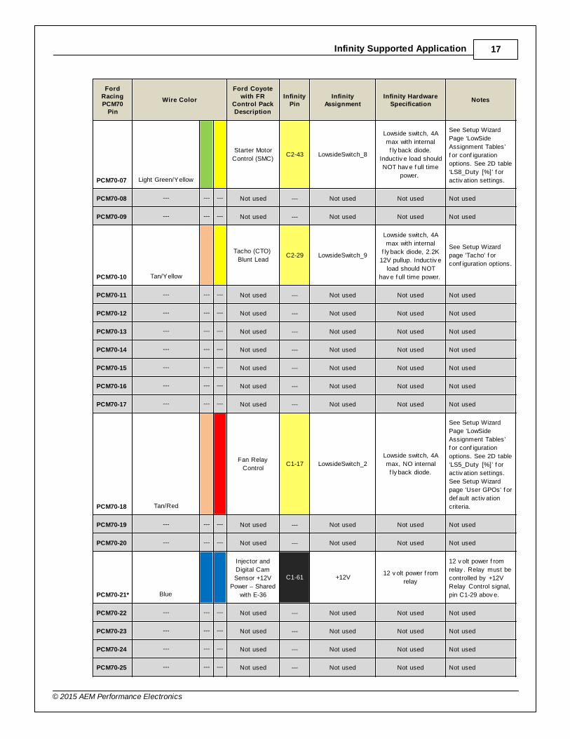
PCM70-07 Light Green/Yellow
Starter Motor
Control (SMC)C2-43 LowsideSwitch_8
Lowside switch, 4A
max with internal
f ly back diode.
Inductiv e load should
NOT hav e f ull time
power.
See Setup Wizard
Page ‘LowSide
Assignment Tables’
f or conf iguration
options. See 2D table
‘LS8_Duty [%]’ f or
activ ation settings.
PCM70-08 --- --- --- Not used --- Not used Not used Not used
PCM70-09 --- --- --- Not used --- Not used Not used Not used
PCM70-10 Tan/Yellow
Tacho (CTO)
Blunt LeadC2-29 LowsideSwitch_9
Lowside switch, 4A
max with internal
f ly back diode, 2.2K
12V pullup. Inductiv e
load should NOT
hav e f ull time power.
See Setup Wizard
page 'Tacho' f or
conf iguration options.
PCM70-11 --- --- --- Not used --- Not used Not used Not used
PCM70-12 --- --- --- Not used --- Not used Not used Not used
PCM70-13 --- --- --- Not used --- Not used Not used Not used
PCM70-14 --- --- --- Not used --- Not used Not used Not used
PCM70-15 --- --- --- Not used --- Not used Not used Not used
PCM70-16 --- --- --- Not used --- Not used Not used Not used
PCM70-17 --- --- --- Not used --- Not used Not used Not used
PCM70-18 Tan/Red
Fan Relay
ControlC1-17 LowsideSwitch_2
Lowside switch, 4A
max, NO internal
f ly back diode.
See Setup Wizard
Page ‘LowSide
Assignment Tables’
f or conf iguration
options. See 2D table
‘LS5_Duty [%]’ f or
activ ation settings.
See Setup Wizard
page 'User GPOs' f or
def ault activ ation
criteria.
PCM70-19 --- --- --- Not used --- Not used Not used Not used
PCM70-20 --- --- --- Not used --- Not used Not used Not used
PCM70-21* Blue
Injector and
Digital Cam
Sensor +12V
Power – Shared
with E-36
C1-61 +12V12 v olt power f rom
relay
12 v olt power f rom
relay . Relay must be
controlled by +12V
Relay Control signal,
pin C1-29 abov e.
PCM70-22 --- --- --- Not used --- Not used Not used Not used
PCM70-23 --- --- --- Not used --- Not used Not used Not used
PCM70-24 --- --- --- Not used --- Not used Not used Not used
PCM70-25 --- --- --- Not used --- Not used Not used Not used

18
© 2015 AEM Performance Electronics
FordRacingPCM70
Pin
Wire Color
Ford Coyotewith FR
Control PackDescription
InfinityPin
InfinityAssignment
Infinity HardwareSpecification
Notes
PCM70-26 --- --- --- Not used --- Not used Not used Not used
PCM70-27 --- --- --- Not used --- Not used Not used Not used
PCM70-28 Tan/Yellow
DBW_APP1
[%]C2-13 Analog_In_18
12 bit A/D, 100K
pullup to 5V
0–5V analog signal.
Use +5V Out pins as
power supply and
Sensor Ground pins
as the low ref erence.
Do not connect
signals ref erenced to
+12V as this can
permanently damage
the ECU.
PCM70-29 Light Blue/White
DBW_APP2
[%]C2-14 Analog_In_19
12 bit A/D, 100K
pullup to 5V
0–5V analog signal.
Use +5V Out pins as
power supply and
Sensor Ground pins
as the low ref erence.
Do not connect
signals ref erenced to
+12V as this can
permanently damage
the ECU.
PCM70-30 --- --- --- Not used --- Not used Not used Not used
PCM70-31 --- --- --- Not used --- Not used Not used Not used
PCM70-32 --- --- --- Not used --- Not used Not used Not used
PCM70-33 --- --- --- Not used --- Not used Not used Not used
PCM70-34 --- --- --- Not used --- Not used Not used Not used
PCM70-35 --- --- --- Not used --- Not used Not used Not used
PCM70-36 --- --- --- Not used --- Not used Not used Not used
PCM70-37 --- --- --- Not used --- Not used Not used Not used
PCM70-38 Brown/Pink
PCM Relay
controlC1-29
+12V_Relay _Contro
l
0.7A max ground sink
f or external relay
control
Will activ ate at key
on and at key of f
according to the
conf iguration
settings.
PCM70-39 --- --- --- Not used --- Not used Not used Not used
PCM70-40 --- --- --- Not used --- Not used Not used Not used
PCM70-41 --- --- --- Not used --- Not used Not used Not used
PCM70-42 Red/Light Green
12V Start &
Run (ISP-R)
Blunt Lead
C1-65 +12V_SW 10K pulldown
Full time battery
power must be
av ailable at C1-10
bef ore this input is
triggered.
PCM70-43 --- --- --- Not used --- Not used Not used Not used

Infinity Supported Application 19
© 2015 AEM Performance Electronics
FordRacingPCM70
Pin
Wire Color
Ford Coyotewith FR
Control PackDescription
InfinityPin
InfinityAssignment
Infinity HardwareSpecification
Notes
PCM70-44* Grey /Red
APP Sensor 1
& 2 Ground
APPVREF (1) &
(2) – Shared
with PCM70-60
C2-32 AGND_2Dedicated analog
ground
Analog 0–5V sensor
ground
PCM70-45 Brown/White
APPVREF (1) C2-22 +5V_Out_2Regulated, f used +5V
supply f or sensor
power
Analog sensor power
PCM70-46 --- --- --- Not used --- Not used Not used Not used
PCM70-47 Grey
Intake Air
TemperatureC1-67 Analog_In_Temp_2
12 bit A/D, 2.49K
pullup to 5V
See 'Air Temperature'
Setup Wizard f or
selection.
PCM70-48 --- --- --- Not used --- Not used Not used Not used
PCM70-49 --- --- --- Not used --- Not used Not used Not used
PCM70-50 Black Case Ground C2-8 Power Ground Power Ground
Connect directly to
battery ground.
PCM70-51 Blue/Yellow
Intercooler
Pump Relay
Control (SCICP
PCM signal)
C1-1 LowsideSwitch_4
Lowside switch, 4A
max, NO internal
f ly back diode.
See Setup Wizard
Page ‘LowSide
Assignment Tables’
f or conf iguration
options. See 2D table
‘LS4_Duty [%]’ f or
activ ation settings.
PCM70-52 --- --- --- Not used --- Not used Not used Not used
PCM70-53 Yellow/Light Blue
GENRC C1-34 LowsideSwitch_0
Lowside switch, 4A
max, NO internal
f ly back diode.
See Setup Wizard
Page ‘LowSide
Assignment Tables’
f or output
assignment and 2D
table ‘LS0_Duty [%]’
f or activ ation.
PCM70-54 --- --- --- Not used --- Not used Not used Not used
PCM70-55 --- --- --- Not used --- Not used Not used Not used
PCM70-56 --- --- --- Not used --- Not used Not used Not used
PCM70-57 --- --- --- Not used --- Not used Not used Not used
PCM70-58 Pink/Light Green
AEMNet CANL C1-31 CANL_Aout
Dedicated High
Speed CAN
Transceiv er
Recommend twisted
pair (one twist per 2")
with terminating
resistor. Contact
AEM f or additional
inf ormation.
PCM70-59 White/Light Green
AEMNet CANH C1-32 CANH_Aout
Dedicated High
Speed CAN
Transceiv er
Recommend twisted
pair (one twist per 2")
with terminating
resistor. Contact
AEM f or additional
inf ormation.

20
© 2015 AEM Performance Electronics
FordRacingPCM70
Pin
Wire Color
Ford Coyotewith FR
Control PackDescription
InfinityPin
InfinityAssignment
Infinity HardwareSpecification
Notes
PCM70-60* Grey
APP Sensor 1
& 2 Ground
APPVREF (1) &
(2) – Shared
with PCM70-44
C2-32 AGND_2Dedicated analog
ground
Analog 0–5V sensor
ground
PCM70-61 Brown
APPVREF (2) C2-23 +5V_Out_2Regulated, f used +5V
supply f or sensor
power
Analog sensor power
PCM70-62 Yellow
KAPWR /
12VHAATC1-10 +12V_R8C_CPU
Dedicated power
management CPU
Full time battery
power. MUST be
powered bef ore the
ignition switch input is
triggered. (See C1-
65.)
PCM70-63 --- --- --- Not used --- Not used Not used Not used
PCM70-64 --- --- --- Not used --- Not used Not used Not used
PCM70-65 --- --- --- Not used --- Not used Not used Not used
PCM70-66 --- --- --- Not used --- Not used Not used Not used
PCM70-67 Grey /Orange
+12V In C1-64 +12V12 v olt power f rom
relay
12 v olt power f rom
relay . Relay must be
controlled by +12V
Relay Control signal
pin C1-29 abov e.
PCM70-68 Grey /Orange
VPWR C2-9 +12V12 v olt power f rom
relay
12 v olt power f rom
relay . Relay must be
controlled by +12V
Relay Control signal,
pin C1-29 abov e.
PCM70-69 Black PWR Ground C1-60 Power Ground Power Ground
Connect directly to
battery ground.
PCM70-70 Black PWR Ground C1-73 Power Ground Power Ground
Connect directly to
battery ground.
* Denotes shared Infinity Pin Location
FordRacingPCM50
Pin
Wire Color
Ford Coyotewith FR
Control PackDescription
InfinityPin
InfinityAssignment
Infinity HardwareSpecification
Notes
PCM50-01 --- --- --- Not used --- Not used Not used Not used
PCM50-02 --- --- --- Not used --- Not used Not used Not used
PCM50-03 --- --- --- Not used --- Not used Not used Not used
PCM50-04 Brown/Pink
U02SN Bank 1 C1-7 UEGO 1 UNBosch UEGO
controller
Nernst Voltage
signal. Connect to pin
1 of Bosch UEGO
sensor.

Infinity Supported Application 21
© 2015 AEM Performance Electronics
FordRacingPCM50
Pin
Wire Color
Ford Coyotewith FR
Control PackDescription
InfinityPin
InfinityAssignment
Infinity HardwareSpecification
Notes
PCM50-05 --- --- --- Not used --- Not used Not used Not used
PCM50-06 --- --- --- Not used --- Not used Not used Not used
PCM50-07 --- --- --- Not used --- Not used Not used Not used
PCM50-08 --- --- --- Not used --- Not used Not used Not used
PCM50-09 --- --- --- Not used --- Not used Not used Not used
PCM50-10 --- --- --- Not used --- Not used Not used Not used
PCM50-11 --- --- --- Not used --- Not used Not used Not used
PCM50-12 --- --- --- Not used --- Not used Not used Not used
PCM50-13 --- --- --- Not used --- Not used Not used Not used
PCM50-14 --- --- --- Not used --- Not used Not used Not used
PCM50-15 Grey /White
UREF Bank 1 C1-8 UEGO 1 VMBosch UEGO
controller
Virtual Ground signal.
Connect to pin 5 of
Bosch UEGO sensor.
PCM50-16 Brown/Light Blue
UO2SIP Bank 2 C2-47 UEGO 2 IPBosch UEGO
controller
Pumping Current
signal. Connect to pin
6 of Bosch UEGO
sensor.
PCM50-17 Light Green
UO2SIP Bank 1 C1-6 UEGO 1 IPBosch UEGO
controller
Pumping Current
signal. Connect to pin
6 of Bosch UEGO
sensor.
PCM50-18 --- --- --- Not used --- Not used Not used Not used
PCM50-19 Light Blue/Yellow
Clutch Position
(Neutral Switch)
Blunt Lead
C2-33 Analog_In_2012 bit A/D, 100K
pullup to 5V
0–5V analog signal.
Use +5V Out pins as
power supply and
Sensor Ground pins
as the low ref erence.
Do not connect
signals ref erenced to
+12V as this can
permanently damage
the ECU. See
ClutchSwitch 1-axis
table f or setup
options. Input can be
assigned to dif f erent
pins. See Setup
Wizard page 'Input
Function
Assignments' f or
input mapping
options.
PCM50-20 --- --- --- Not used --- Not used Not used Not used
PCM50-21 --- --- --- Not used --- Not used Not used Not used
PCM50-22 --- --- --- Not used --- Not used Not used Not used
22
© 2015 AEM Performance Electronics
FordRacingPCM50
Pin
Wire Color
Ford Coyotewith FR
Control PackDescription
InfinityPin
InfinityAssignment
Infinity HardwareSpecification
Notes
PCM50-23 --- --- --- Not used --- Not used Not used Not used
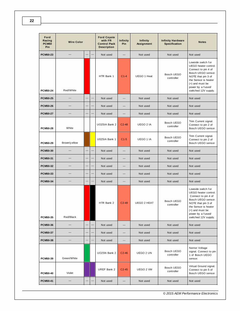
PCM50-24 Red/White
HTR Bank 1 C1-4 UEGO 1 Heat Bosch UEGO
controller
Lowside switch f or
UEGO heater control.
Connect to pin 4 of
Bosch UEGO sensor.
NOTE that pin 3 of
the Sensor is heater
(+) and must be
power by a f used/
switched 12V supply .
PCM50-25 --- --- --- Not used --- Not used Not used Not used
PCM50-26 --- --- --- Not used --- Not used Not used Not used
PCM50-27 --- --- --- Not used --- Not used Not used Not used
PCM50-28 White
UO2SIA Bank 2 C2-48 UEGO 2 IABosch UEGO
controller
Trim Current signal.
Connect to pin 2 of
Bosch UEGO sensor.
PCM50-29 Brown/y ellow
U02SIA Bank 1 C1-5 UEGO 1 IABosch UEGO
controller
Trim Current signal.
Connect to pin 2 of
Bosch UEGO sensor.
PCM50-30 --- --- --- Not used --- Not used Not used Not used
PCM50-31 --- --- --- Not used --- Not used Not used Not used
PCM50-32 --- --- --- Not used --- Not used Not used Not used
PCM50-33 --- --- --- Not used --- Not used Not used Not used
PCM50-34 --- --- --- Not used --- Not used Not used Not used
PCM50-35 Red/Black
HTR Bank 2 C2-49 UEGO 2 HEATBosch UEGO
controller
Lowside switch f or
UEGO heater control.
Connect to pin 4 of
Bosch UEGO sensor.
NOTE that pin 3 of
the Sensor is heater
(+) and must be
power by a f used/
switched 12V supply .
PCM50-36 --- --- --- Not used --- Not used Not used Not used
PCM50-37 --- --- --- Not used --- Not used Not used Not used
PCM50-38 --- --- --- Not used --- Not used Not used Not used
PCM50-39 Green/White
UO2SN Bank 2 C2-46 UEGO 2 UNBosch UEGO
controller
Nernst Voltage
signal. Connect to pin
1 of Bosch UEGO
sensor.
PCM50-40 Violet
UREF Bank 2 C2-45 UEGO 2 VMBosch UEGO
controller
Virtual Ground signal.
Connect to pin 5 of
Bosch UEGO sensor.
PCM50-41 --- --- --- Not used --- Not used Not used Not used

Infinity Supported Application 23
© 2015 AEM Performance Electronics
FordRacingPCM50
Pin
Wire Color
Ford Coyotewith FR
Control PackDescription
InfinityPin
InfinityAssignment
Infinity HardwareSpecification
Notes
PCM50-42 --- --- --- Not used --- Not used Not used Not used
PCM50-43 --- --- --- Not used --- Not used Not used Not used
PCM50-44 --- --- --- Not used --- Not used Not used Not used
PCM50-45 --- --- --- Not used --- Not used Not used Not used
PCM50-46 --- --- --- Not used --- Not used Not used Not used
PCM50-47 --- --- --- Not used --- Not used Not used Not used
PCM50-48 --- --- --- Not used --- Not used Not used Not used
PCM50-49 --- --- --- Not used --- Not used Not used Not used
PCM50-50 --- --- --- Not used --- Not used Not used Not used

24
© 2015 AEM Performance Electronics
Infinity Pinouts
Dedicated Dedicated and not reconfigurable
Assigned Assigned but reconfigurable
Available Available for user setup
Not Applicable Not used in this configuration
Required Required for proper function
InfinityPin
Infinity AssignmentPin
Destination
Ford Coyote with FRControl PackDescription
Infinity HardwareSpecification
Notes
C1-1 LowsideSwitch_4Ford Racing
PCM70-51
Intercooler Pump Relay
Control (SCICP PCM
signal)
Lowside switch, 4A max,
NO internal f ly back
diode.
'See Setup Wizard Page 'LowSide
Assignment Tables' f or
conf iguration options. See 2D table
'LS4_Duty [%]' f or activ ation
settings.
C1-2 LowsideSwitch_5Engine
E-16
Variable Camshaf t
Timing 21 Solenoid
(Driv erside Intake)
Lowside switch, 4A max
with internal f ly back
diode. Inductiv e load
should NOT hav e f ull
time power.
'See Setup Wizard Page 'LowSide
Assignment Tables' f or
conf iguration options. See 2D table
'LS5_Duty [%]' f or activ ation
settings. See Setup Wizard page
'VVC' f or options.
C1-3 LowsideSwitch_6Engine
E-56
Variable Camshaf t
Timing 12 Solenoid
(Passengerside Exhaust)
Lowside switch, 4A max
with internal f ly back
diode. Inductiv e load
should NOT hav e f ull
time power.
'See Setup Wizard Page 'LowSide
Assignment Tables' f or
conf iguration options. See 2D table
'LS6_Duty [%]' f or activ ation
settings. See Setup Wizard page
'VVC' f or options.
C1-4 UEGO 1 Heat --- UEGO 1 Heat
Bosch UEGO controller
Lowside switch f or UEGO heater
control. Connect to pin 4 of Bosch
UEGO sensor. NOTE that pin 3 of
the Sensor is heater (+) and must
be power by a f used/switched 12V
supply .
C1-5 UEGO 1 IA --- UEGO 1 IATrim Current signal. Connect to pin
2 of Bosch UEGO sensor.
C1-6 UEGO 1 IP --- UEGO 1 IPPumping Current signal. Connect
to pin 6 of Bosch UEGO sensor.
C1-7 UEGO 1 UN --- UEGO 1 UNNernst Voltage signal. Connect to
pin 1 of Bosch UEGO sensor.
C1-8 UEGO 1 VM --- UEGO 1 VMVirtual Ground signal. Connect to
pin 5 of Bosch UEGO sensor.
C1-9 Flash_Enable --- Flash Enable 10K pulldown
Not usually needed f or automatic
f irmware updates through Inf inity
Tuner. If connection errors occur
during update, connect 12 v olts to
this pin bef ore proceeding with
upgrade. Disconnect the 12 v olts
signal af ter the update.

Infinity Supported Application 25
© 2015 AEM Performance Electronics
InfinityPin
Infinity AssignmentPin
Destination
Ford Coyote with FRControl PackDescription
Infinity HardwareSpecification
Notes
C1-10 +12V_R8C_CPUFord Racing
PCM70-62KAPWR / 12VHAAT
Dedicated power
management CPU
Full time battery power. MUST be
powered bef ore the ignition switch
input is triggered. (See C1-65.)
C1-11 Coil 4Engine
E-50
Coil on Plug Assembly 4
(COP4C)
25 mA max source
current
0–5V Falling edge f ire. DO NOT
connect directly to coil primary .
Must use an ignitor OR CDI that
accepts a FALLING edge f ire
signal.
C1-12 Coil 3Engine
E-18
Coil on Plug Assembly 3
(COP3F)
25 mA max source
current
0–5V Falling edge f ire. DO NOT
connect directly to coil primary .
Must use an ignitor OR CDI that
accepts a FALLING edge f ire
signal.
C1-13 Coil 2Engine
E-52
Coil on Plug Assembly 2
(COP2H)
25 mA max source
current
0–5V Falling edge f ire. DO NOT
connect directly to coil primary .
Must use an ignitor OR CDI that
accepts a FALLING edge f ire
signal.
C1-14 Coil 1Engine
E-70
Coil on Plug Assembly 1
(COP1A)
25 mA max source
current
0–5V Falling edge f ire. DO NOT
connect directly to coil primary .
Must use an ignitor OR CDI that
accepts a FALLING edge f ire
signal.
C1-15 Coil 6Engine
E-69
Coil on Plug Assembly 6
(COP6E)
25 mA max source
current
0–5V Falling edge f ire. DO NOT
connect directly to coil primary .
Must use an ignitor OR CDI that
accepts a FALLING edge f ire
signal.
C1-16 Coil 5Engine
E-34
Coil on Plug Assembly 5
(COP5B)
25 mA max source
current
0–-5V Falling edge f ire. DO NOT
connect directly to coil primary .
Must use an ignitor OR CDI that
accepts a FALLING edge f ire
signal.
C1-17 LowsideSwitch_2Ford Racing
PCM70-18Fan Relay Control
Lowside switch, 4A max,
NO internal f ly back
diode.
See Setup Wizard Page 'LowSide
Assignment Tables' f or
conf iguration options. See 2D table
'LS5_Duty [%]' f or activ ation
settings. See Setup Wizard page
'User GPOs' f or def ault activ ation
criteria.
C1-18 LowsideSwitch_3Engine
E-02
Variable Camshaf t
Timing 11 Solenoid
(Passengerside Intake)
Lowside switch, 4A max
with internal f ly back
diode. Inductiv e load
should NOT hav e f ull
time power.
See Setup Wizard Page 'LowSide
Assignment Tables' f or
conf iguration options. See 2D table
'LS3_Duty [%]' f or activ ation
settings. See Setup Wizard page
'VVC' f or options.
C1-19 AGND_1Ford Racing
PCM70-02
IAT
Sensor GroundDedicated analog ground Analog 0–5V sensor ground
C1-20 AGND_1Engine
E-32
Digital Cams Ground (E-
SIGRTN)Dedicated analog ground Analog 0–5V sensor ground

26
© 2015 AEM Performance Electronics
InfinityPin
Infinity AssignmentPin
Destination
Ford Coyote with FRControl PackDescription
Infinity HardwareSpecification
Notes
C1-21Crankshaf t Position
Sensor Hall---
Crankshaf t Position
Sensor Hall
10K pullup to 12V. Will
work with ground or
f loating switches.
See Setup Wizard page 'Cam/
Crank' f or options.
C1-22Camshaf t Position
Sensor 1 Hall
Engine
E-41
Camshaf t Position Bank
1 (Passenger Intake)
(CMP11)
10K pullup to 12V. Will
work with ground or
f loating switches.
See Setup Wizard page 'Cam/
Crank' f or options.
C1-23 Digital_In_2Engine
E-42
Camshaf t Position Bank
2 (Driv erside Intake)
(CMP21)
10K pullup to 12V. Will
work with ground or
f loating switches.
See Setup Wizard page 'Cam/
Crank' f or options.
C1-24 Digital_In_3 --- Turbo Speed Hz
10K pullup to 12V. Will
work with ground or
f loating switches.
See Setup Wizard page 'Input
Function Assignment' f or
calibration constant. TurboSpeed
[RPM] = Turbo [Hz] * Turbo Speed
Calibration.
C1-25 Digital_In_4 --- Vehicle Speed Sensor10K pullup to 12V. Will
work with ground or
f loating switches.
See Setup Wizard page 'Input
Function Assignment' f or
calibration constant.
C1-26 Digital_In_5 --- Flex Fuel10K pullup to 12V. Will
work with ground or
f loating switches.
See channel FlexDigitalIn [Hz] f or
raw f requency input data.
C1-27 Knock Sensor 1Engine
E-07 Knock Sensor + [KS1+]
Dedicated knock signal
processor
See Setup Wizard page 'Knock
Setup' f or options.
C1-28 Knock Sensor 2Engine
E-45Knock Sensor+ [KS2+]
Dedicated knock signal
processor
See Setup Wizard page 'Knock
Setup' f or options.
C1-29 +12V_Relay _ControlFord Racing
PCM70-38PCM Relay control
0.7A max ground sink f or
external relay control
Will activ ate at key on and at key
of f according to the conf iguration
settings.
C1-30 Power GroundEngine
E-11
Crankshaf t Position
Sensor Shield (SHDRTN)Power Ground Connect directly to battery ground.
C1-31 CANL_AoutFord Racing
PCM70-58AEMNet CANL
Dedicated High Speed
CAN Transceiv er
Recommend twisted pair (one twist
per 2") with terminating resistor.
Contact AEM f or additional
inf ormation.
C1-32 CANH_AoutFord Racing
PCM70-59AEMNet CANH
Dedicated High Speed
CAN Transceiv er
Recommend twisted pair (one twist
per 2") with terminating resistor.
Contact AEM f or additional
inf ormation.
C1-33 LowsideSwitch_1 --- Boost Control
Lowside switch, 4A max
with internal f ly back
diode. Inductiv e load
should NOT hav e f ull
time power.
See Setup Wizard Page 'LowSide
Assignment Tables' f or
conf iguration options. See 2D table
'LS1_Duty [%]' f or activ ation
settings. See Setup Wizard page
'Boost Control' f or options. Monitor
BoostControl [%] channel f or
output state.

Infinity Supported Application 27
© 2015 AEM Performance Electronics
InfinityPin
Infinity AssignmentPin
Destination
Ford Coyote with FRControl PackDescription
Infinity HardwareSpecification
Notes
C1-34 LowsideSwitch_0Ford Racing
PCM70-53GENRC
Lowside switch, 4A max,
NO internal f ly back
diode.
See Setup Wizard Page 'LowSide
Assignment Tables' f or output
assignment and 2D table
'LS0_Duty [%]' f or activ ation.
C1-35 Analog_In_7Engine
E-39
DBW Negativ e Slope
(TP1)
12 bit A/D, 100K pullup to
5V
0–5V analog signal. Use +5V Out
pins as power supply and Sensor
Ground pins as the low ref erence.
Do not connect signals ref erenced
to +12V as this can permanently
damage the ECU. See the Setup
Wizard Set Throttle Range page f or
automatic min/max calibration.
Monitor the Throttle [%] channel.
Also DB1_TPSA [%] f or DBW
applications.
C1-36 Analog_In_8 --- MAP Sensor12 bit A/D, 100K pullup to
5V
0–5V analog signal. Use +5V Out
pins as power supply and Sensor
Ground pins as the low ref erence.
Do not connect signals ref erenced
to +12V as this can permanently
damage the ECU. See the Setup
Wizard Set Manif old Pressure page
f or setup and calibration. Monitor
the MAP [kPa] channel.
C1-37 Analog_In_9 --- Fuel Pressure12 bit A/D, 100K pullup to
5V
0–5V analog signal. Use +5V Out
pins as power supply and Sensor
Ground pins as the low ref erence.
Do not connect signals ref erenced
to +12V as this can permanently
damage the ECU. See the Setup
Wizard Fuel Pressure page f or
setup and calibration. Monitor the
FuelPressure [psig] channel.
C1-38 Analog_In_10 --- Baro Sensor12 bit A/D, 100K pullup to
5V
0–5V analog signal. Use +5V Out
pins as power supply and Sensor
Ground pins as the low ref erence.
Do not connect signals ref erenced
to +12V as this can permanently
damage the ECU. See the Setup
Wizard Barometric Pressure page
f or setup and calibration. Monitor
the BaroPress [kPa] channel.
C1-39 Analog_In_11 --- Shif t Switch Input12 bit A/D, 100K pullup to
5V
0–5V analog signal. Use +5V Out
pins as power supply and Sensor
Ground pins as the low ref erence.
Do not connect signals ref erenced
to +12V as this can permanently
damage the ECU.
See the 1D lookup table
'Shif tSwitch' f or setup. Also
assignable to multiple f unctions.
See Setup Wizard f or details.

28
© 2015 AEM Performance Electronics
InfinityPin
Infinity AssignmentPin
Destination
Ford Coyote with FRControl PackDescription
Infinity HardwareSpecification
Notes
C1-40 Analog_In_12 --- Mode Switch12 bit A/D, 100K pullup to
5V
0–5V analog signal. Use +5V Out
pins as power supply and Sensor
Ground pins as the low ref erence.
Do not connect signals ref erenced
to +12V as this can permanently
damage the ECU.
See the 1D lookup table
'ModeSwitch' f or input state.
A multi-position rotary switch such
as AEM P/N 30-2056 is
recommended.
Also assignable to multiple
f unctions. See Setup Wizard f or
details.
C1-41 +5V_Out_1Engine
E-09
'Electronic Throttle
Control (ETCREF)
Regulated, f used +5V
supply f or sensor powerAnalog sensor power
C1-42 +5V_Out_1 --- +5V OutRegulated, f used +5V
supply f or sensor powerAnalog sensor power
C1-43 HighsideSwitch_1 --- HS1 (switched 12V)0.7A max, High Side
Solid State Relay
See Setup Wizard page 'HighSide
Assigment Tables' f or conf iguration
options. See 2D lookup table
'HS1_Table' f or activ ation settings.
C1-44 HighsideSwitch_0 --- VTEC0.7A max, High Side
Solid State Relay
See Setup Wizard page 'HighSide
Assigment Tables' f or conf iguration
options. See 2D lookup table
'HS0_Table' f or activ ation settings.
See Setup Wizard page 'Honda
VTEC' f or def ault activ ation
criteria.
C1-45Crankshaf t Position
Sensor VR+
Engine
E-13
Crankshaf t Position
(CKP+)Dif f erential Variable
Reluctance Zero Cross
Detection
See Setup Wizard page 'Cam/
Crank' f or options.
C1-46Crankshaf t Position
Sensor VR-
Engine
E-12
Crankshaf t Position
Sensor (CKP-)
C1-47Camshaf t Position
Sensor 1 VR-
Engine
E-29
VR Reluctance Sensor
(VRSRTN)Dif f erential Variable
Reluctance Zero Cross
Detection
See Setup Wizard page 'Cam/
Crank' f or options.
C1-48Camshaf t Position
Sensor 1 VR+
Engine
E-46
Camshaf t Position Bank
1 In (Passengerside
Exhaust) (CMP12)
C1-49 VR+_In_2Engine
E-47
Camshaf t Position Bank
2 In (Driv erside Exhaust)
(CMP22) Dif f erential Variable
Reluctance Zero Cross
Detection
See Setup Wizard page 'Cam/
Crank' f or options.
C1-50 VR-_In_2Engine
E-48
Variable Reluctance
Sensor (VRSRTN2)
C1-51 VR-_In_3 ---Driv en Lef t Wheel Speed
Sensor -
Dif f erential Variable
Reluctance Zero Cross
Detection
See 'Driv en Wheel Speed
Calibration' in the Setup Wizard
'Input Function Assignment' page.

Infinity Supported Application 29
© 2015 AEM Performance Electronics
InfinityPin
Infinity AssignmentPin
Destination
Ford Coyote with FRControl PackDescription
Infinity HardwareSpecification
Notes
C1-52 VR+_In_3 ---Driv en Lef t Wheel Speed
Sensor +
C1-53 DBW1 Motor -Engine
E-67
Throttle Actuator Control
Motor (TACM-)
5.0A max Throttle Control
Hbridge Driv e+12V to close
C1-54 DBW1 Motor +Engine
E-68
Throttle Actuator Control
Motor(TACM+)
5.0A max Throttle Control
Hbridge Driv e+12V to open
C1-55 Power Ground --- Ground Power Ground Connect directly to battery ground.
C1-56 Injector 6Engine
E-64
Fuel Injector Driv er 6
(INJ6)
Saturated or peak and
hold, 3A max continuousInjector 6
C1-57 Injector 5Engine
E-63
Fuel Injector Driv er 5
(INJ5)
Saturated or peak and
hold, 3A max continuousInjector 5
C1-58 Injector 4Engine
E-62
Fuel Injector Driv er 4
(INJ4)
Saturated or peak and
hold, 3A max continuousInjector 4
C1-59 Injector 3Engine
E-55
Fuel Injector Driv er 3
(INJ3)
Saturated or peak and
hold, 3A max continuousInjector 3
C1-60 Power GroundFord Racing
PCM70-69PWR Ground Power Ground Connect directly to battery ground.
C1-61 +12V
Ford
Racing
PCM70-21 &
Engine E-36
Injector and Digital Cam
Sensor +12V Power12 v olt power f rom relay
12 v olt power f rom relay . Relay
must be controlled by +12V Relay
Control signal, pin C1-29 abov e.
C1-62 Injector 2Engine
E-54
Fuel Injector Driv er 2
(INJ2)
Saturated or peak and
hold, 3A max continuousInjector 2
C1-63 Injector 1Engine
E-53
Fuel Injector Driv er 1
(INJ1)
Saturated or peak and
hold, 3A max continuousInjector 1
C1-64 +12VFord Racing
PCM70-67+12V In 12 v olt power f rom relay
12 v olt power f rom relay . Relay
must be controlled by +12V Relay
Control signal pin C1-29 abov e.
C1-65 +12V_SWFord Racing
PCM70-42
12V Start & Run (ISP-R)
Blunt Lead10K pulldown
Full time battery power must be
av ailable at C1-10 bef ore this input
is triggered.
C1-66 Analog_In_Temp_1Engine
E-30
Cy linder Head
Temperature (CHT)
12 bit A/D, 2.49K pullup
to 5V
See 'Coolant Temperature' Setup
Wizard f or selection.
C1-67 Analog_In_Temp_2Ford Racing
PCM70-47Intake Air Temperature
12 bit A/D, 2.49K pullup
to 5V
See 'Air Temperature' Setup Wizard
f or selection.

30
© 2015 AEM Performance Electronics
InfinityPin
Infinity AssignmentPin
Destination
Ford Coyote with FRControl PackDescription
Infinity HardwareSpecification
Notes
C1-68 Analog_In_Temp_3 --- Oil Temperature Sensor12 bit A/D, 2.49K pullup
to 5V
See 'Oil Temperature' Setup Wizard
f or selection.
C1-69 Stepper_2A --- Stepper 2A
Automotiv e,
Programmable Stepper
Driv er, up to 28V and
±1.4A
Be sure that each internal coil of
the stepper motor is properly
paired with the 1A/1B and 2A/2B
ECU outputs. Supports Bi-Polar
stepper motors only . See Setup
Wizard page 'Idle – Show
Adv anced Setup' f or options.
C1-70 Stepper_1A --- Stepper 1A
Automotiv e,
Programmable Stepper
Driv er, up to 28V and
±1.4A
Be sure that each internal coil of
the stepper motor is properly
paired with the 1A/1B and 2A/2B
ECU outputs. Supports Bi-Polar
stepper motors only . See Setup
Wizard page 'Idle – Show
Adv anced Setup' f or options.
C1-71 Stepper_2B --- Stepper 2B
Automotiv e,
Programmable Stepper
Driv er, up to 28V and
±1.4A
Be sure that each internal coil of
the stepper motor is properly
paired with the 1A/1B and 2A/2B
ECU outputs. Supports Bi-Polar
stepper motors only . See Setup
Wizard page 'Idle – Show
Adv anced Setup' f or options.
C1-72 Stepper_1B --- Stepper 1B
Automotiv e,
Programmable Stepper
Driv er, up to 28V and
±1.4A
Be sure that each internal coil of
the stepper motor is properly
paired with the 1A/1B and 2A/2B
ECU outputs. Supports Bi-Polar
stepper motors only . See Setup
Wizard page 'Idle – Show
Adv anced Setup' f or options.
C1-73 Power GroundFord Racing
PCM70-70PWR Ground Power Ground Connect directly to battery ground.
C2-1 DBW2 Motor + -- DBW Motor Control Open5.0A max Throttle Control
Hbridge Driv e+12V to open
C2-2 DBW2 Motor - --DBW Motor Control
Close
5.0A max Throttle Control
Hbridge Driv e+12V to close
C2-3 Power Ground -- Ground Power Ground Connect directly to battery ground.
C2-4 Injector 7Engine
E-65
Fuel Injector Driv er 7
(INJ7)
Saturated or peak and
hold, 3A max continuousInjector 7
C2-5 Injector 8Engine
E-66
Fuel Injector Driv er 8
(INJ8)
Saturated or peak and
hold, 3A max continuousInjector 8
C2-6 Injector 9 --- Injector 9Saturated or peak and
hold, 3A max continuousInjector 9

Infinity Supported Application 31
© 2015 AEM Performance Electronics
InfinityPin
Infinity AssignmentPin
Destination
Ford Coyote with FRControl PackDescription
Infinity HardwareSpecification
Notes
C2-7 Injector 10 --- Injector 10Saturated or peak and
hold, 3A max continuousInjector 10
C2-8 Power GroundFord Racing
PCM70-50Case Ground Power Ground Connect directly to battery ground.
C2-9 +12VFord
Racing
PCM70-68
VPWR 12 v olt power f rom relay12 v olt power f rom relay . Relay
must be controlled by +12V Relay
Control signal, pin C1-29 abov e.
C2-10 Injector 11 --- Injector 11Saturated or peak and
hold, 3A max continuousNot used
C2-11 Injector 12 --- Injector 12Saturated or peak and
hold, 3A max continuousNot used
C2-12 Analog_In_17 --- A/C Analog Request12 bit A/D, 100K pullup to
5V
0–5V analog signal. Use +5V Out
pins as power supply and Sensor
Ground pins as the low ref erence.
Do not connect signals ref erenced
to +12V as this can permanently
damage the ECU. See Setup
Wizard 'Input Functions' page f or
input selection. See
AC_Request_In 1-axis table f or
activ ation logic.
C2-13 Analog_In_18Ford Racing
PCM70-28DBW_APP1 [%]
12 bit A/D, 100K pullup to
5V
0–5V analog signal. Use +5V Out
pins as power supply and Sensor
Ground pins as the low ref erence.
Do not connect signals ref erenced
to +12V as this can permanently
damage the ECU.
C2-14 Analog_In_19Ford Racing
PCM70-29DBW_APP2 [%]
12 bit A/D, 100K pullup to
5V
0–5V analog signal. Use +5V Out
pins as power supply and Sensor
Ground pins as the low ref erence.
Do not connect signals ref erenced
to +12V as this can permanently
damage the ECU.
C2-15 Analog_In_Temp_4 --- Charge Out Temperature12 bit A/D, 2.49K pullup
to 5V
See ChargeOutTemp [C] table f or
calibration data and
ChargeOutTemp [C] f or channel
data.
C2-16 Analog_In_Temp_5 --- Airbox Temperature12 bit A/D, 2.49K pullup
to 5V
See AirboxTemp [C] table f or
calibration data and AirboxTemp
[C] f or channel data.
C2-17 Analog_In_Temp_6 --- Fuel Temperature12 bit A/D, 2.49K pullup
to 5V
See FuelTemp [C] table f or
calibration data and FuelTemp [C]
f or channel data.

32
© 2015 AEM Performance Electronics
InfinityPin
Infinity AssignmentPin
Destination
Ford Coyote with FRControl PackDescription
Infinity HardwareSpecification
Notes
C2-18 Analog_In_13 --- Oil Pressure12 bit A/D, 100K pullup to
5V
0–5V analog signal. Use +5V Out
pins as power supply and Sensor
Ground pins as the low ref erence.
Do not connect signals ref erenced
to +12V as this can permanently
damage the ECU. See Setup
Wizard 'Oil Pressure' page f or
setup options. See OilPressure
[psig] f or channel data.
C2-19 Analog_In_14 ---Traction Control Mode /
Sensitiv ity
12 bit A/D, 100K pullup to
5V
0–5V analog signal. Use +5V Out
pins as power supply and Sensor
Ground pins as the low ref erence.
Do not connect signals ref erenced
to +12V as this can permanently
damage the ECU. See the
TC_SlipTrgtTrim [MPH] 1-axis
table. A multi-position rotary switch
such as AEM P/N 30-2056 is
recommended.
C2-20 Analog_In_15 --- Exhaust Back Pressure12 bit A/D, 100K pullup to
5V
0–5V analog signal. Use +5V Out
pins as power supply and Sensor
Ground pins as the low ref erence.
Do not connect signals ref erenced
to +12V as this can permanently
damage the ECU. See Setup
Wizard 'Exhaust Pressure' page f or
setup options. See EBPress [kPa]
f or channel data.
C2-21 Analog_In_16Engine
E-10
Throttle Position #
Positiv e Slope (TP2)
12 bit A/D, 100K pullup to
5V
0–5V analog signal. Use +5V Out
pins as power supply and Sensor
Ground pins as the low ref erence.
Do not connect signals ref erenced
to +12V as this can permanently
damage the ECU.
C2-22 +5V_Out_2Ford Racing
PCM70-45APPVREF (1)
Regulated, f used +5V
supply f or sensor powerAnalog sensor power
C2-23 +5V_Out_2Ford Racing
PCM70-61APPVREF (2)
Regulated, f used +5V
supply f or sensor powerAnalog sensor power
C2-24 +5V_Out_2 --- +5V OutRegulated, f used +5V
supply f or sensor powerAnalog sensor power
C2-25 VR+_In_5 ---Driv en Right Wheel
Speed Sensor +Dif f erential Variable
Reluctance Zero Cross
Detection
See Driv en Wheel Speed
Calibration in the Setup Wizard
'Input Function Assignment' page.C2-26 VR-_In_5 ---
Driv en Right Wheel
Speed Sensor -
C2-27 VR-_In_4 ---Non Driv en Right Wheel
Speed Sensor -Dif f erential Variable
Reluctance Zero Cross
Detection
See Non Driv en Wheel Speed
Calibration in the Setup Wizard
'Input Function Assignment' page.C2-28 V R+_In_4 ---
Non Driv en Right Wheel
Speed Sensor +

Infinity Supported Application 33
© 2015 AEM Performance Electronics
InfinityPin
Infinity AssignmentPin
Destination
Ford Coyote with FRControl PackDescription
Infinity HardwareSpecification
Notes
C2-29 LowsideSwitch_9Ford Racing
PCM70-10Tacho (CTO) Blunt Lead
Lowside switch, 4A max
with internal f ly back
diode, 2.2K 12V pullup.
Inductiv e load should
NOT hav e f ull time
power.
See Setup Wizard page 'Tacho' f or
conf iguration options.
C2-30 AGND_2Engine
E-08DBW Ground (ETCRTN) Dedicated analog ground Analog 0–5V sensor ground
C2-31 AGND_2Engine E-06
&
Engine E-44
Knock Sensor 1 & 2
Ground [KS1 - & KS2 -]Dedicated analog ground Analog 0–5V sensor ground
C2-32 AGND_2
Ford Racing
PCM70-44
&
PCM70-60
APP Sensor 1 & 2
Ground
APPVREF (1) & (2)
Dedicated analog ground Analog 0–5V sensor ground
C2-33 Analog_In_20Ford Racing
PCM50-19
Clutch Position (Neutral
Switch) Blunt Lead
12 bit A/D, 100K pullup to
5V
0–5V analog signal. Use +5V Out
pins as power supply and Sensor
Ground pins as the low ref erence.
Do not connect signals ref erenced
to +12V as this can permanently
damage the ECU. See
ClutchSwitch 1-axis table f or setup
options. Input can be assigned to
dif f erent pins. See Setup Wizard
page 'Input Function Assignments'
f or input mapping options.
C2-34 Analog_In_21 ---3 Step Enable Switch /
TPS2A
12 bit A/D, 100K pullup to
5V
0–5V analog signal. Use +5V Out
pins as power supply and Sensor
Ground pins as the low ref erence.
Do not connect signals ref erenced
to +12V as this can permanently
damage the ECU. See 3StepSwitch
1-axis table f or setup.
C2-35 Analog_In_22 --- USB Logging Activ ate12 bit A/D, 100K pullup to
5V
0–5V analog signal. Use +5V Out
pins as power supply and Sensor
Ground pins as the low ref erence.
Do not connect signals ref erenced
to +12V as this can permanently
damage the ECU. See
USBLoggingRequestIn channel f or
input state. See Setup Wizard page
'USB Logging' f or conf iguration
options.
C2-36 Analog_In_23 ---Charge Out Pressure /
TPS2B
12 bit A/D, 100K pullup to
5V
0–5V analog signal. Use +5V Out
pins as power supply and Sensor
Ground pins as the low ref erence.
Do not connect signals ref erenced
to +12V as this can permanently
damage the ECU. See
ChargeOutPress [kPa] channel f or
input state. See Setup Wizard page
'Charge Out Pressure' f or
calibration options.

34
© 2015 AEM Performance Electronics
InfinityPin
Infinity AssignmentPin
Destination
Ford Coyote with FRControl PackDescription
Infinity HardwareSpecification
Notes
C2-37 Digital_In_6 --- Spare Digital InputNo pullup. Will work with
TTL signals.
Input can be assigned to dif f erent
pins. See Setup Wizard page Input
Function Assignments f or input
mapping options.
C2-38 Digital_In_7 --- Brake SwitchNo pullup. Will work with
TTL signals.
See BrakeSwitch 1-axis table f or
setup options. Input can be
assigned to dif f erent pins. See
Setup Wizard page 'Input Function
Assignments' f or input mapping
options.
C2-39 Power Ground --- Ground Power Ground Connect directly to battery ground.
C2-40 Power Ground --- Ground Power Ground Connect directly to battery ground.
C2-41 CanH_Bout --- CANHDedicated High Speed
CAN Transceiv erNot used
C2-42 CanL_Bout --- CANLDedicated High Speed
CAN Transceiv erNot used
C2-43 LowsideSwitch_8Ford Racing
PCM70-07
Starter Motor Control
(SMC)
Lowside switch, 4A max
with internal f ly back
diode. Inductiv e load
should NOT hav e f ull
time power.
See Setup Wizard Page 'LowSide
Assignment Tables' f or
conf iguration options. See 2D table
'LS8_Duty [%]' f or activ ation
settings.
C2-44 LowsideSwitch_7Engine
E-57
Variable Camshaf t
Timing 22 Solenoid
(Driv erside Exhaust)
Lowside switch, 4A max
with internal f ly back
diode. Inductiv e load
should NOT hav e f ull
time power.
See Setup Wizard Page 'LowSide
Assignment Tables' f or
conf iguration options. See 2D table
'LS7_Duty [%]' f or activ ation
settings. See Setup Wizard page
'VVC' f or options.
C2-45 UEGO 2 VM --- UEGO 2 VM
Bosch UEGO Controller
Virtual Ground signal. Connect to
pin 5 of Bosch UEGO sensor.
C2-46 UEGO 2 UN --- UEGO 2 UNNernst Voltage signal. Connect to
pin 1 of Bosch UEGO sensor.
C2-47 UEGO 2 IP --- UEGO 2 IPPumping Current signal. Connect
to pin 6 of Bosch UEGO sensor.
C2-48 UEGO 2 IA --- UEGO 2 IATrim Current signal. Connect to pin
2 of Bosch UEGO sensor.
C2-49 UEGO 2 HEAT --- UEGO 2 HEAT
Lowside switch f or UEGO heater
control. Connect to pin 4 of Bosch
UEGO sensor. NOTE that pin 3 of
the Sensor is heater (+) and must
be power by a f used/switched 12V
supply .

Infinity Supported Application 35
© 2015 AEM Performance Electronics
InfinityPin
Infinity AssignmentPin
Destination
Ford Coyote with FRControl PackDescription
Infinity HardwareSpecification
Notes
C2-50 +12V_R8C_CPU --- Battery Perm PowerDedicated power
management CPU
Optional f ull time battery power.
MUST be powered bef ore the
ignition switch input is triggered.
(See C1-65.)
C2-51 Coil 7Engine
E-33
Coil on Plug Assembly 7
(COP7G)
25 mA max source
current
0–5V Falling edge f ire. DO NOT
connect directly to coil primary .
Must use an ignitor OR CDI that
accepts a FALLING edge f ire
signal.
C2-52 Coil 8Engine
E-51
Coil on Plug Assembly 8
(COP8D)
25 mA max source
current
0–5V Falling edge f ire. DO NOT
connect directly to coil primary .
Must use an ignitor OR CDI that
accepts a FALLING edge f ire
signal.
C2-53 Coil 9 --- Coil 925 mA max source
current
0–5V Falling edge f ire. DO NOT
connect directly to coil primary .
Must use an ignitor OR CDI that
accepts a FALLING edge f ire
signal.
C2-54 Coil 10 --- Coil 1025 mA max source
current
0–5V Falling edge f ire. DO NOT
connect directly to coil primary .
Must use an ignitor OR CDI that
accepts a FALLING edge f ire
signal.
C2-55 HighsideSwitch_2
User Mod.
Fuel Pump
Control
(C47-01
Green w/
Black Stripe
wire);
See Page
5–6.
Fuel Pump
Multi-f unction pin
depending on hardware
conf iguration
See Setup Wizard page 'HighSide
Assignment Tables' f or
conf iguration options. See 2D
lookup table 'HS1_Table' f or
activ ation settings. See Setup
Wizard page 'User GPOs' f or
def ault activ ation criteria.
C2-56 Not used Not used Not used Not used
Ford Pin Numbering
Ford Coyote PCM Connectors Viewed from Wire Side

36
© 2015 AEM Performance Electronics
Infinity Pin Numbering
AEM Infinity Connectors Viewed from Wire Side

Infinity Supported Application 37
© 2015 AEM Performance Electronics
12 MONTH LIMITED WARRANTY
Advanced Engine Management Inc. warrants to the consumer that all AEM HighPerformance products will be free from defects in material and workmanship for aperiod of twelve (12) months from date of the original purchase. Products that fail withinthis 12-month warranty period will be repaired or replaced at AEM’s option, whendetermined by AEM that the product failed due to defects in material or workmanship.This warranty is limited to the repair or replacement of the AEM part. In no event shallthis warranty exceed the original purchase price of the AEM part nor shall AEM beresponsible for special, incidental or consequential damages or cost incurred due to thefailure of this product. Warranty claims to AEM must be transportation prepaid andaccompanied with dated proof of purchase. This warranty applies only to the originalpurchaser of product and is non-transferable. All implied warranties shall be limited induration to the said 12-month warranty period. Improper use or installation, accident,abuse, unauthorized repairs or alterations voids this warranty. AEM disclaims anyliability for consequential damages due to breach of any written or implied warranty onall products manufactured by AEM. Warranty returns will only be accepted by AEM whenaccompanied by a valid Return Merchandise Authorization (RMA) number. Productmust be received by AEM within 30 days of the date the RMA is issued.
Please note that before AEM can issue an RMA for any electronic product, it is firstnecessary for the installer or end user to contact the EMS tech line at 1-800-423-0046 todiscuss the problem. Most issues can be resolved over the phone. Under nocircumstances should a system be returned or a RMA requested before the aboveprocess transpires.
AEM will not be responsible for electronic products that are installed incorrectly, installedin a non-approved application, misused, or tampered with.
Any AEM electronics product can be returned for repair if it is out of the warranty period.There is a minimum charge of $50.00 for inspection and diagnosis of AEM electronicparts. Parts used in the repair of AEM electronic components will be extra. AEM willprovide an estimate of repairs and receive written or electronic authorization beforerepairs are made to the product.