ford code reader - static.summitracing.com2)1.pdfinnova 3143 1 ford code o f f reader ... read...
TRANSCRIPT
Ford Innova 1998
FORD CODE READER
FOR FORD, LINCOLN, MERCURYDOMESTIC VEHICLES FROM 1981 TO 1995
FORDCODE
READER
Domestic vehicles • 1981 to 1995
O F F
AUDIOON
HOLD
TEST
FORD • LINCOLN • MERCURY
E C M • A B S
INNOVA 3143

Table of Contents
i Ford
Paragraph Title Page No.
YOU CAN DO IT!............................................................ ii
GENERAL INFORMATION1.1 YOUR VEHICLE'S COMPUTER SYSTEMS................ 1-11.2 ABOUT YOUR CODE READER.................................... 1-11.3 SAFETY PRECAUTIONS .............................................. 1-31.4 VEHICLE SERVICE MANUALS .................................. 1-41.5 PRELIMINARY VEHICLE DIAGNOSIS ..................... 1.5
WORKSHEET1.6 DIAGNOSTIC ROUTINE CHECKLIST........................ 1-8
ECM2.1 VEHICLES COVERED .................................................. 2-12.2 TEST CONNECTORS LOCATION ............................... 2-22.3 OPTIONAL EXTENSION CABLE ................................ 2-42.4 BEFORE YOU BEGIN .................................................. 2-5
EEC-IV SYSTEMS2.5 RETRIEVING FAULT CODES FOR ............................ 2-5
EEC-IV SYSTEMS2.6 ADDITIONAL TESTS FOR EEC-IV SYSTEMS...............2-122.7 ERASING "CONTINUOUS MEMORY" ........................2-17
CODES FOR EEC-IV SYSTEMS2.8 FAULT CODE DEFINITIONS FOR..............................2-17
EEC-IV SYSTEMS / CAR & TRUCK)2.9 RETRIEVING FAULT CODES FOR ............................2-33
MCU SYSTEMS2.10 FAULT CODE DEFINITIONS FOR MCU....................2-37
SYSTEMS / CAR & TRUCK
ABS3.1 VEHICLES COVERED .................................................. 3-13.2 TEST CONNECTOR LOCATION.................................. 3-13.3 RETRIEVING ABS FAULT CODES ............................. 3-23.4 ERASING ABS CODES.................................................. 3-33.5 ABS FAULT CODE DEFINITIONS.............................. 3-3
GLOSSARY4.1 INTRODUCTION ........................................................... 4-14.2 GLOSSARY OF TERMS AND ...................................... 4-1
ABBREVIATIONS
WARRANTY AND SERVICE5.1 LIMITED ONE YEAR WARRANTY.............................. 5-15.2 SERVICE PROCEDURES.............................................. 5-1
You Can Do It!
Ford ii
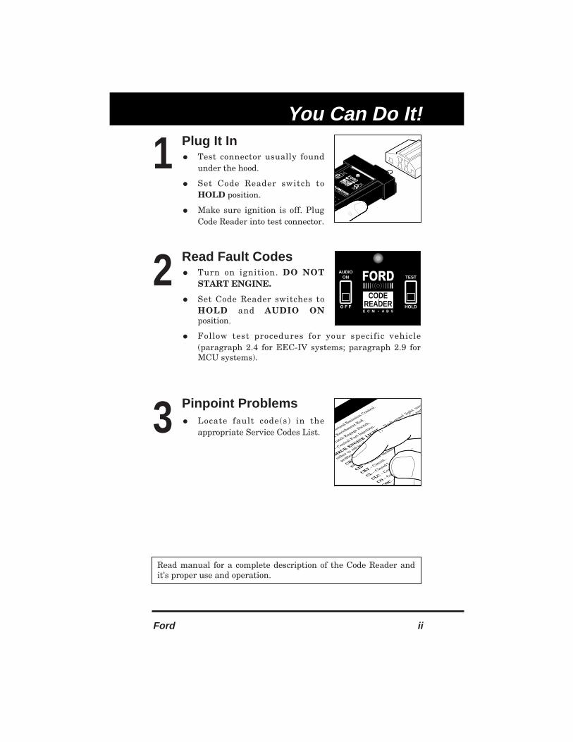
Plug It In• Test connector usually found
under the hood.
• Set Code Reader switch to
HOLD position.
• Make sure ignition is off. PlugCode Reader into test connector.
Read Fault Codes• Turn on ignition. DO NOT
START ENGINE.
• Set Code Reader switches toHOLD and AUDIO ONposition.
• Follow test procedures for your specific vehicle(paragraph 2.4 for EEC-IV systems; paragraph 2.9 forMCU systems).
Pinpoint Problems• Locate fault code(s) in the
appropriate Service Codes List.
FORDCODEREADER
les • 1981 to 1995
O F F
AUDIOON
HOLD
TESTNCOLN • MERCURY
E C M • A B S
INNOVA
3143
1
FORDCODE
READERO F F
AUDIOON
HOLD
TEST
E C M • A B S
2
3
uterized Emiss
ion Control.
d Enrichment R
od.
Clutch Engage Switch
.
– Central F
uel Injectio
n.
CHECK ENGINE LIG
HT – Dash panel li
ght used
either to
aid in id
entification and diagnosis
of a sy
st
problems or to
indicate th
at maintenance is
require
CHECK VALVE – Valve that o
perates like a
gate.
CID – Cylin
der Identifi
cation sensor o
r it
CKT – Circuit.
CL – Closed Loop.
CLC – Converter L
ock-up Clut
CO – Carbon Monoxide.
COC – Conventional Oxi
OMPUTER TIM
es before top d
Cranksh
e
Read manual for a complete description of the Code Reader andit's proper use and operation.

1
1-1 Ford
1.1 YOUR VEHICLE'S COMPUTER SYSTEMS
Today's vehicles are equipped with computer systems whichhelp control the vehicle's operation and performance. ThePowertrain Control Module, also called the Engine ControlModule (ECM), Engine Control Unit (ECU) or Engine ControlComputer (ECC) helps control the engine's operation andincrease overall performance. Typical control includes fueldelivery, idle speed control, spark timing, and emissionsystems. The Electronic Brake Control Module (EBCM)controls the vehicle's Anti-Lock Brake System (ABS).
In addition to controlling operation of the associated vehiclesystems, the computers are equipped with self-diagnosticprogramming. When a fault is detected, the computer storesthis information in it's memory as a fault code.
1.1.1 Fault Codes
The fault codes are also called "diagnostic codes" or "troublecodes". These codes can be used to identify systems orcomponents which are malfunctioning.
The computer records codes for two types of problems:
■
"Hard" Codes. "Hard" codes are stored for problemswhich are present at the time of testing.
■ "Intermittent" Codes or "Continuous Memory"Codes. "Intermittent" codes are stored for problems whichhappened in the past but are not currently present at thetime of testing. "Intermittent" codes stay in the computer'smemory even when the problem is no longer present.
1.2 ABOUT YOUR CODE READER
The Code Reader is a tool which allows you to retrieve thesefault codes from the computer's memory. The Code Reader willnot damage the vehicle's computer systems.

General Information
Ford 1-2
1.2.1 Controls and Indicators
1. LED Indicator – Blinks on/off to give you service codesfrom the vehicle's onboard computers.
2. AUDIO ON/OFF Switch – Turns audio indicator on andoff. Useful when the LED indicator cannot be seen.
■ ON – A tone soundswhenever the LED indicatorlights.
■ OFF – No tone.
3. TEST/HOLD Switch – Controls the vehicle's onboardcomputer Self-Test input ground loop.
■ TEST – Testing starts.
■ HOLD – On hold, notesting.
FORDCODE
READER
Domestic vehicles • 1981 to 1995
O F F
AUDIOON
HOLD
TEST
FORD • LINCOLN • MERCURY
E C M • A B S
INNOVA 3143
3
1
2
O F F
AUDIOON
HOLD
TEST

1
1-3 Ford
1.2.2 Preparing The Code Reader For Use
1. Installing The Battery
• 9-volt battery required toperform tests.
• Battery sold separately.
a. Remove the batterycompartment cover from theback of the Code Reader.
b. Match battery terminalswith battery connectorcontacts.
c. Snap battery connectorsecurely onto battery, andplace battery into batterycompartment.
d. Reinstall battery compartment cover.
2. Checking The Battery
a. Set Code Reader switch toTEST.
b. Set AUDIO ON/OFF switchto ON.
c. Using a jumper wire or apiece of metal, touch thetwo side-by-side terminalson the bottom row of theCode Reader connector.
d. If the battery is good, the LED indicator will light anda tone will sound. If the tone or LED indicator getsweak, replace the battery.
1.3 SAFETY PRECAUTIONS
• Always observe safety precautions whenever working on avehicle.
a. Always wear safety eye protection.
b. Only work on your vehicle in a well-ventilated area.
9V9VFORD
CODEREADERO F F
AUDIOON
HOLD
TEST
E C M • A B S
General Information
Ford 1-4
c. Put transmission in “park” (for automatic) or “neutral” (formanual). Set parking brake.
d. Put blocks on drive wheels.
e. Avoid moving fan blades or any potentially moving parts.
f. Avoid hot engine parts.
g. Turn off ignition before connecting (or disconnecting) anytesting equipment.
h. Please read your vehicle’s service manual and follow it’ssafety procedure.
1.4 VEHICLE SERVICE MANUALS
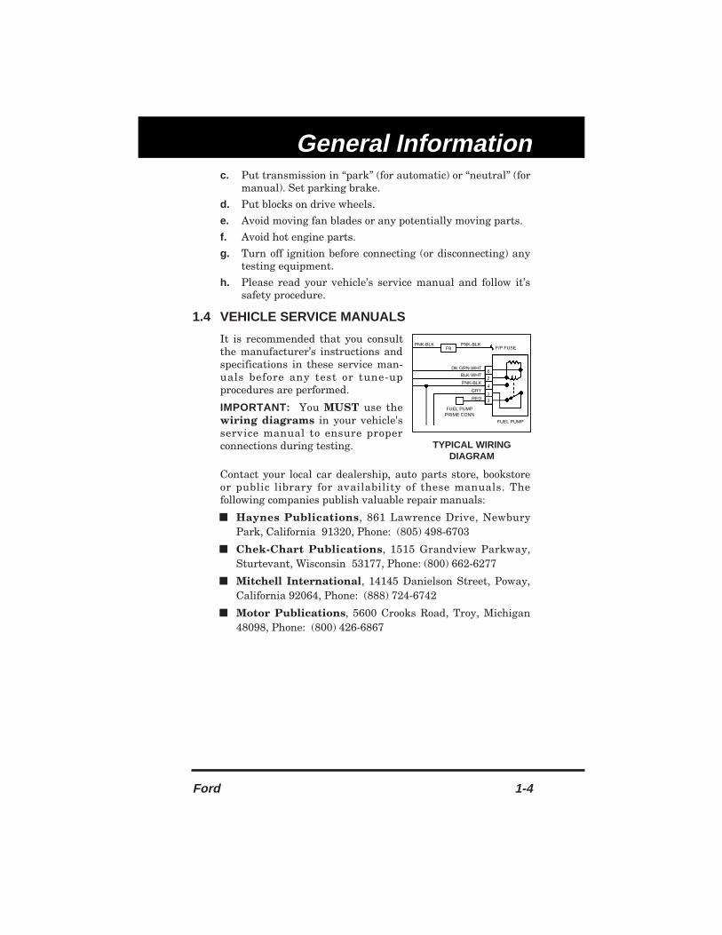
It is recommended that you consultthe manufacturer’s instructions andspecifications in these service man-uals before any test or tune-upprocedures are performed.
IMPORTANT: You MUST use thewiring diagrams in your vehicle'sservice manual to ensure properconnections during testing.
Contact your local car dealership, auto parts store, bookstoreor public library for availability of these manuals. Thefollowing companies publish valuable repair manuals:
■ Haynes Publications, 861 Lawrence Drive, NewburyPark, California 91320, Phone: (805) 498-6703
■ Chek-Chart Publications, 1515 Grandview Parkway,Sturtevant, Wisconsin 53177, Phone: (800) 662-6277
■ Mitchell International, 14145 Danielson Street, Poway,California 92064, Phone: (888) 724-6742
■ Motor Publications, 5600 Crooks Road, Troy, Michigan48098, Phone: (800) 426-6867
F8PNK-BLK PNK-BLK
F/P FUSE
DK GRN-WHT
BLK-WHT
PNK-BLK
GRY
RED
FUEL PUMPPRIME CONN
FUEL PUMP
6
2
4
1
3
TYPICAL WIRINGDIAGRAM

1
1-5 Ford
1.5 PRELIMINARY VEHICLE DIAGNOSIS WORKSHEET
The purpose of this form is to help you gather preliminary informationon your vehicle before you retrieve codes. By having a completeaccount of your vehicle's current problem(s), you will be able tosystematically pinpoint the problem(s) by comparing your answers tothe fault codes you retrieve. You can also provide this information toyour mechanic to assist in diagnosis and help avoid costly andunnecessary repairs. It is important for you to complete this form to helpyou and/or your mechanic have a clear understanding of your vehicle'sproblems.
NAME:
DATE:
VIN*:
YEAR:
MAKE:
MODEL:
ENGINE SIZE:
VEHICLE MILEAGE:
*VIN: Vehicle Identification Number, found at the base of thewindshield on a metallic plate, or at the driver door latch area (consultyour vehicle owner's manual for location).
TRANSMISSION:
❑ Automatic
❑ Manual
Please check all applicable items in each category.
DESCRIBE THE PROBLEM:
General Information
Ford 1-6
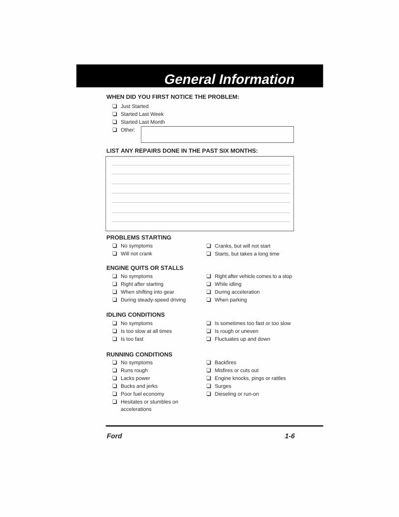
WHEN DID YOU FIRST NOTICE THE PROBLEM:
❑ Just Started
❑ Started Last Week
❑ Started Last Month
❑ Other:
LIST ANY REPAIRS DONE IN THE PAST SIX MONTHS:
PROBLEMS STARTING
ENGINE QUITS OR STALLS
IDLING CONDITIONS
RUNNING CONDITIONS
❑ No symptoms
❑ Will not crank
❑ Cranks, but will not start
❑ Starts, but takes a long time
❑ No symptoms
❑ Right after starting
❑ When shifting into gear
❑ During steady-speed driving
❑ Right after vehicle comes to a stop
❑ While idling
❑ During acceleration
❑ When parking
❑ No symptoms
❑ Is too slow at all times
❑ Is too fast
❑ Is sometimes too fast or too slow
❑ Is rough or uneven
❑ Fluctuates up and down
❑ No symptoms
❑ Runs rough
❑ Lacks power
❑ Bucks and jerks
❑ Poor fuel economy
❑ Hesitates or stumbles on accelerations
❑ Backfires
❑ Misfires or cuts out
❑ Engine knocks, pings or rattles
❑ Surges
❑ Dieseling or run-on

1
1-7 Ford
AUTOMATIC TRANSMISSION PROBLEMS (if applicable)
PROBLEM OCCURS
❑ Morning ❑ Afternoon ❑ Anytime
ENGINE TEMPERATURE WHEN PROBLEM OCCURS
❑ Cold ❑ Warm ❑ Hot
DRIVING CONDITIONS WHEN PROBLEM OCCURS
DRIVING HABITS
GASOLINE USED
WEATHER CONDITIONS WHEN PROBLEM OCCURS
CHECK ENGINE LIGHT / DASH WARNING LIGHT
❑ Sometimes ON ❑ Always ON ❑ Never ON
PECULIAR SMELLS
STRANGE NOISES
❑ Short - less than 2 miles❑ 2 ~ 10 miles❑ Long - more than 10 miles❑ Stop and go❑ While turning❑ While braking❑ At gear engagement❑ With A/C operating
❑ With headlights on❑ During acceleration❑ Mostly driving downhill❑ Mostly driving uphill❑ Mostly driving level❑ Mostly driving curvy roads❑ Mostly driving rough roads
❑ Mostly city driving❑ Highway❑ Park vehicle inside❑ Park vehicle outside
❑ Drive less than 10 miles per day❑ Drive 10 to 50 miles per day❑ Drive more than 50 miles per day
❑ 87 Octane❑ 89 Octane
❑ 91 Octane❑ More than 91 Octane
❑ 32 ~ 55° F (0 ~ 13° C)❑ Below freezing (32° F / 0° C)
❑ Above 55° F (13° C)
❑ "Hot"❑ Sulfur ("rotten egg")❑ Burning rubber
❑ Gasoline❑ Burning oil❑ Electrical
❑ Rattle❑ Knock
❑ Squeak❑ Other
❑ No symptoms❑ Shifts too early or too late❑ Changes gear incorrectly
❑ Vehicle does not move when in
gear❑ Jerks or bucks

General Information
Ford 1-8
1.6 DIAGNOSTIC ROUTINE CHECKLIST
Step Procedure Instruction/YES Instruction/NO"A" Perform checks (para- Go to Step "B"
graph 2.4)"B" Note symptoms Go to Step "C""C" Evaluate Diagnostic Go to Step "D"
Routine Chart1
"D" Evaluate Quick Test Go to Step "E"Description1
"E" Perform visual in- Go to Step "F"spection
"F" Prepare vehicle Go to Step "G""G" Connect Code Reader Go to Step "H"
to vehicle"H" Perform "KOEO" Test Go to Step "I" If Code 11 or
(paragraph 2.5.1 for 111 (systemEEC-IV Systems, OK) displays,paragraph 2.9.1 for go to Step "J"MCU Systems)
"I" Erase codes, test drive Code(s) Present? If Code 11 orvehicle (if possible), Note all codes 111 (systemand repeat "KOEO" and go to Step OK) displays,Test (if vehicle will "I-1" go to Step "J"not start, go to Step"M")
"I-1" Refer to "Fault Code Go to Step "I-2"Definitions" and find and eliminatefaults faults, in order,
one at a time"I-2" Perform all Pinpoint Tests OK? Refer Failed test(s)?
Tests1 associated with to Service man- Repair problemfault (as outlined in ual for proper and return toyour specific vehicle's course of action. Step "I"Service Manual After repair, go
to Step "H""J" Perform "KOER" Test Code(s) Present? If Code 11 or
(paragraph 2.5.3 for Note all codes 111 (systemEEC-IV Systems, and go to Step OK) displays,paragraph 2.9.3 for "J-1" go to Step "L"MCU Systems) (if vehicle will not start,go to Step "M")

1
1-9 Ford
1 Diagnostic Routine Chart, Quick Test, Pinpoint Test, andSwitch Monitor Test data are found in Manufacturer'sService manuals.
Step Procedure Instruction/YES Instruction/NO"J-1" Erase codes, test drive Code(s) Present? If Code 11 or
vehicle (if possible), Note all codes 111 (systemand repeat "KOER" and go to Step OK) displays,Test "K" go to Step "L"
"K" Refer to "Fault Code Go to Step "K-1"Definitions" and find and eliminatefaults faults, in order,
one at a time"K-1" Perform all Pinpoint Tests OK? Refer Failed test(s)?
Tests1 associated with to Service man- Repair problemfault (as outlined in ual for proper and return toyour specific vehicle's course of action. Step "J-1"Service Manual After repair, go
to Step "J""L" Perform Switch All switches OK? One or more
Monitor Test1 Go to Step "N" switches notOK? Go to Step "K-1"
"M" Perform appropriateQuick Test1
"N" Return to Diagnostic Find procedureRoutine Chart1 and go to Step
"K-1" or end test

General Information
Ford 1-10
2
2-1 Ford
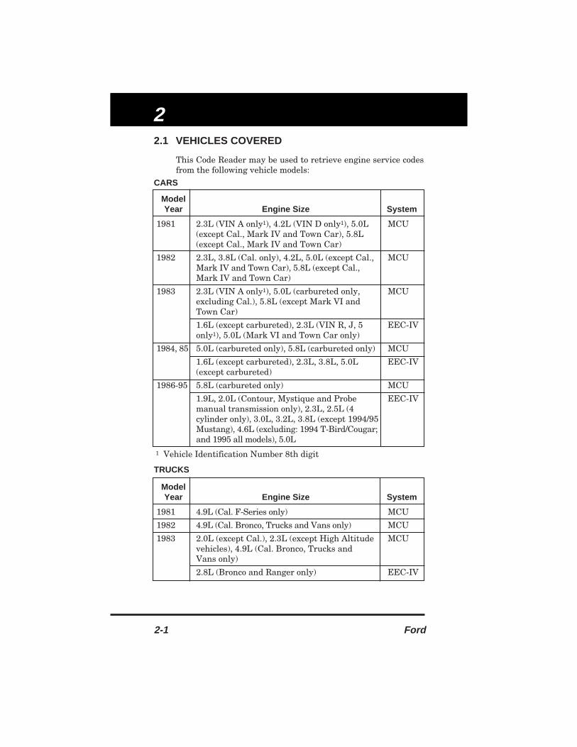
2.1 VEHICLES COVERED
This Code Reader may be used to retrieve engine service codesfrom the following vehicle models:
CARS
1 Vehicle Identification Number 8th digit
TRUCKS
ModelYear Engine Size System
1981 2.3L (VIN A only1), 4.2L (VIN D only1), 5.0L MCU(except Cal., Mark IV and Town Car), 5.8L (except Cal., Mark IV and Town Car)
1982 2.3L, 3.8L (Cal. only), 4.2L, 5.0L (except Cal., MCUMark IV and Town Car), 5.8L (except Cal.,Mark IV and Town Car)
1983 2.3L (VIN A only1), 5.0L (carbureted only, MCUexcluding Cal.), 5.8L (except Mark VI andTown Car)
1.6L (except carbureted), 2.3L (VIN R, J, 5 EEC-IVonly1), 5.0L (Mark VI and Town Car only)
1984, 85 5.0L (carbureted only), 5.8L (carbureted only) MCU
1.6L (except carbureted), 2.3L, 3.8L, 5.0L EEC-IV(except carbureted)
1986-95 5.8L (carbureted only) MCU
1.9L, 2.0L (Contour, Mystique and Probe EEC-IVmanual transmission only), 2.3L, 2.5L (4 cylinder only), 3.0L, 3.2L, 3.8L (except 1994/95 Mustang), 4.6L (excluding: 1994 T-Bird/Cougar;and 1995 all models), 5.0L
ModelYear Engine Size System
1981 4.9L (Cal. F-Series only) MCU
1982 4.9L (Cal. Bronco, Trucks and Vans only) MCU
1983 2.0L (except Cal.), 2.3L (except High Altitude MCUvehicles), 4.9L (Cal. Bronco, Trucks andVans only)
2.8L (Bronco and Ranger only) EEC-IV

ECM
Ford 2-2
2.2 TEST CONNECTORS LOCATION
• The gateway to your vehicle's onboard computer.
Your vehicle test connectors are usually dark in color andfound under the hood. Sometimes they have a plastic cover overthem or are labeled EEC Test. The connectors can be found inthe following general locations in the engine compartment:
• Near the front corner (right or left).
• Near the fender well (right or left).
• Near the fire wall (right or left).
ModelYear Engine Size System
1984 2.0L (except Cal.), 2.3L (except High Altitude MCUvehicles)
2.8L, 4.9L (vehicles under 8500 lbs only), 5.0L EEC-IV(Cal. and vehicles under 8500 lbs only, 5.8L(vehicles under 8500 lbs, High Altitudevehicles, Bronco, and F-150/250)
1985 2.3L (except carbureted), 2.8L (carbureted EEC-IVonly), 4.9L (carbureted vehicles under 8500lbs only), 5.0L, 5.8L (carbureted, E and FSeries A/T only)
1986-95 *2.3L (except carbureted), 2.8L (carbureted EEC-IVonly), 2.9L (except carbureted), *3.0L (exceptcarbureted), *4.0L, 4.9L, 5.0L (except carbu-reted), 5.8L (except carbureted), 7.3L (dieselonly), 7.5L (except carbureted)
*Excludes: 1993-95 Villager, 1995 Ranger andWindstar
EEC-IV TEST CONNECTOR MCU TEST CONNECTOR
6-PIN 6-PIN
SINGLEPIN

2
2-3 Ford
For the EEC-IV Computer System (most vehicles built after1984) connect the Code Reader to
BOTH.
1. large, six pin female connector with molded housing2. small, single pin female connector
For the MCU System (most vehicles built between 1981-1983)connect the Code Reader to the six pin female connector only.
NOTE:
The Code Reader is designed to match the computer'stest connector. When properly connected, the testconnector should match the pre-molded guidesaround the Code Reader pins (as shown below).
Forcing the test connector onto the Code Readerimproperly may result in damage to the Code Readerand possible damage to the vehicle's computersystem.
1988 and newer vehicles may have more than one similarconnector for other systems (i.e. Anti-Lock Brakes), only theconnector with an extra single pin is the correct test connectorfor computer service codes use. If you have any questionsabout the correct connector please refer to your vehicle'sservice manual for detailed information.
NOTE: The 6-pin MCU Test Connectors for some vehiclemodels are not equipped with a ground terminal atposition "F". The Code Reader MUST see the signalprovided by this terminal to initiate code retrieval fromthe vehicles computer.
EEC-IV TESTCONNECTOR
MCU TESTCONNECTOR
CODEREADER
TESTCONNECTOR
NO CONNECTION

ECM
Ford 2-4
If no codes are displayed duringtesting procedure, check the TestConnector for ground terminal atposition "F". If no terminal ispresent, connect a jumper wire fromthe open terminal on the CodeReader to a known good chassisground point on the vehicle.
2.3 OPTIONAL EXTENSION CABLE
For one man operation, a 6' optionalextension cable for test connectionsis available through your local storeor service department. The extensioncable allows you to do all the codereading without the help of anotherperson.
2.4 BEFORE YOU BEGIN
• Fix any known mechanical problems before performingany test.
Make a thorough check before starting any test procedure.Loose or damaged hoses, wiring or electrical connectors areoften responsible for poor engine performance, and in somecases they may cause a "false" fault code.
Please read your vehicle's service manual for properconnection of vacuum hoses, electrical wiring and wiringharness connectors. Check the following areas:
a. All fluid levels - check the oil, power steering, trans-mission (if applicable), coolant and other engine fluids.
b. Air cleaner and ducts - check for holes, rips, excessivedirt in filter, and for disconnected ducts. You may wish tocheck your owner's manual to determine when you shouldchange the air filter.
c. Belts - check for ripped, torn, brittle, loose or missing belts.d. Mechanical linkage associated with sensors - Refer
to your vehicle's service manual for locations.
JUMP TOGROUND
"F"FO
RD
FOR
D

2
2-5 Ford
e. Rubber (vacuum/fuel) and steel hoses - check for leaks,cracks, blockage or other damage; check for proper routing.
f. Spark plugs and wires - check for damaged, loose,disconnected or missing spark plug wires.
g. Battery terminals - make sure battery terminals areclean and tight; check for corrosion or broken connections.Verify proper battery and charging system voltage.
h. Electrical connectors and wiring - make sure wireinsulation is in good condition and there are no exposedwires. Make sure all cables are connected securely.
i. Refer to the Diagnostic Routine Checklist (paragraph 1.5).
2.5 RETRIEVING FAULT CODES FOR EEC-IVSYSTEMS
2.5.1 (KOEO) Key On Engine Off Test
• Always observe safety precautions before and duringtesting process.
• ALWAYS check Code Reader battery before retrievingfault codes.
• Fix any known mechanical problems before this test.
• Warm-up engine to operating temperature before this test.
• Have pencil and paper handy.
1. Turn off ignition.
2. Set Code Reader switch toHOLD and Audio switch toOFF, then connect to the vehicletest connectors (both large andsmall connectors).
3. Do the following:
■ For 4.9L engines: depress clutch until all codes aresent (steps 4 through 6).
■ For 7.3L diesel engines ONLY: depress acceleratoruntil all codes are sent (steps 4 through 6).
■ For 2.3L turbo engines with octane switch: put switchin premium position.
NOTE: Do not depress throttle during this test unlessinstructed.
4. Turn on ignition. DO NOT START THE ENGINE.
FORDCODE
READERO F F
AUDIOON
HOLD
TEST
E C M • A B S

ECM
Ford 2-6
5. Set Code Reader switch toTEST and Audio switch to ON.The KOEO test will begin atthis time. It may take up to oneminute before any codes aresent. You may hear clickingsounds from the engine. This is normal.
6. Read codes on LED. If LED does not blink, check CodeReader battery and repeat KOEO test. If LED still doesnot blink, refer to vehicle's service manual troubleshootingsection. Ignore rapid blinking which occurs before theregular codes are sent. Count blinks to read fault codes.Be sure to write the codes down (codes may be 2 or 3 digitslong).
■ Code 22 looks like:
■ Code 233 looks like:
Codes are separated by a longer pause.
■ Codes 23 and 32 look like:
Two groups of codes are sent. The groups are separated bya "separator flash". The "separator flash" is a single flashthat is sent 6 to 9 seconds after the last KOEO code. Theseparator flash looks like:
The first code group (KOEO) has codes for problems whichare current (hard codes).
FORDCODE
READERO F F
AUDIOON
HOLD
TEST
E C M • A B S
BLINK BLINK
BLINK BLINK= Code 233
BLINK
PAUSE
BLINK BLINKBLINK
PAUSE
BLINK BLINK
PAUSE
BLINK BLINK
= Code 22
BLINK
1ST CODEGROUP
VERY LONG PAUSE VERY LONG PAUSE 2ND CODEGROUP
SEPARATOR FLASH
BLINK BLINK
BLINK BLINK= Codes 23 & 32
BLINK
BLINK BLINKBLINK
PAUSE
BLINKBLINK
PAUSE
LONG PAUSE

2■ The first group will have code 11 or 111 if the system
is OK.
■ The first code group is transmitted twice.The second code group is sent 6 to 9 seconds after the"separator flash", and contains Continuous Memorycodes — for problems which have happened in the pastbut are not present at the time of testing.
■ The Continuous Memory group will have code 11 or111 if the system is o.k.
■ The Continuous Memory code group is transmittedtwice.
An example can be shown with KOEO (hard) codes 15 and28 and continuous memory code 42. Codes 15 and 28 willbe sent in sequence 15 and 28 then repeated 15 and 28.After the "separator flash", the continuous memory code42 will be transmitted and then repeated.
7. To make sure that the codes displayed are "real" faults,erase the codes (paragraph 2.7) and repeat the KOEO Test(paragraph 2.5.1).
NOTE: It may be necessary to test drive the vehicle toreset some fault codes.
8. When codes are sent, write down codes, in order. Usingthe above example, the faults registered are:
9. Service the codes in the order received, beginning with thefirst code of the KOEO (hard) codes group, Code 15 in theabove example.
■ Refer to the "Fault Code Definitions" to determine thefault.
■ Refer to your vehicles Service Manual and follow theappropriate procedures to troubleshoot the fault.
■ Make the necessary repairs to correct the fault.
■ After repairs have been made, erase the codes(paragraph 2.7) and repeat the KOEO Test(paragraph 2.5.1).
2-7 Ford
"SEPARATORFLASH"
KOEO (HARD) CODES1ST CODE GROUP
CONTINUOUS MEMORY CODES2ND CODE GROUP
15 28 42
2ND CODE1ST CODE 1ST CODE

ECM10. If the fault has been corrected, the displayed codes will
not contain Code 15:
NOTE: Elimination of one fault may cause other relatedfaults to be eliminated.
11. Take the next step in sequence (Code 28 in the aboveexample) and perform the troubleshooting and repairprocedures outlined in step 9. If the problem was corrected,the KOEO Test will display Code 11 or Code 111 (SystemOK). In most cases, when KOEO (hard) faults areeliminated, Continuous Memory faults will also beeliminated.
12. If any previous faults return, perform the troubleshootingand repair procedures outlined in step 9 until all faultsare eliminated.
NOTE: Refer to the "Diagnostic Routine Checklist"(paragraph 1.5) for proper fault eliminationprocedures.
13. When fault finding and repairs are completed, turn offignition and Code Reader, and disconnect Code Readerfrom vehicle.
2.5.2 Engine Timing Check
• This procedure is used to check ignition timing and toverify the computer's ability to advance and retard timing.
• Always observe safety precautions before and during Self-Test.
• ALWAYS check Code Reader battery before retrievingfault codes.
• A timing light is required to perform this test.
• The vehicle must pass the KOEO test before performingthis test.
A. 1992 And Older Vehicles (excluding diesel engines)
1. Turn off ignition.
Ford 2-8
"SEPARATORFLASH"
KOEO (HARD) CODES1ST CODE GROUP
CONTINUOUS MEMORY CODES2ND CODE GROUP
28 42
1ST CODE 1ST CODE

22. Set Code Reader switch to
HOLD and Audio switch toOFF, then connect to the vehicletest connectors (both large andsmall connectors).
3. Start engine.
4. Set Code Reader switch toTEST and Audio switch to ON.
5. Wait until LED stops blinking(all the service codes have beensent).
6. Check Ignition Timing with a timing light.
■ Timing degrees remain fixed for only 2 minutes afterthe codes are sent.
■ Within this 2 minute period, the timing degreesshould be advanced about 20° more than the basetiming value (± 3°).
NOTE
: Base timing specifications can be found on theVehicle Emission Control Information (VECI)decal. The decal is located under the hood ornear the radiator. If the VECI decal is missing ordamaged, refer to your vehicle's service manualfor specifications.
■ Example: If base value is 5°, the acceptable range willbe 22° to 28° BTDC. If the timing is off, refer to thevehicle's service manual for instructions on adjusting orrepairing the timing.
7. Turn off ignition and remove the Code Reader.
B. 1992 And Newer Vehicles (excluding diesel engines)
1. Turn off ignition.
2. Turn off all electrical accessories inside vehicle.
3. Disconnect the In-Line Spark Output Signal (SPOUT) orSpark Advance Word (SAW) Connector (located close toignition module), which disconnects computer advancetiming signal from ignition system.
NOTE: Please refer to your vehicle's service manual forany questions regarding the SPOUT and SAWconnector's location and how to disconnect theseconnectors.
4. Start engine.
2-9 Ford
FORDCODE
READERO F F
AUDIOON
HOLD
TEST
E C M • A B S
FORDCODE
READERO F F
AUDIOON
HOLD
TEST
E C M • A B S

ECM
Ford 2-10
5. Check ignition timing with a timing light and make suretiming is within the Vehicle Emission Control Information(VECI) decal specification, (± 2°). VECI decal is located inthe engine compartment.
Example: If specification is 5°, the acceptable range willbe 3° to 7°BTDC.
If base timing is incorrect refer to vehicle's service manualfor instructions on adjusting or repairing the base timing.(Base timing is 10° BTDC if not specified).
6. Reconnect the In-Line SPOUT or SAW Connector.
7. Turn off ignition.
2.5.3 (KOER) Key On Engine Running Test
• Always observe safety precautions before and duringtesting process.
• ALWAYS check Code Reader battery before retrievingfault codes.
• Engine timing check (paragraph 2.5.2) must be performed be-fore the KOER Test is performed (except diesel engines).
1. Turn off ignition.
2. Set Code Reader switch toHOLD and Audio switch toOFF, then connect to the vehicletest connectors (both large andsmall connectors).
3. Start engine and allow engine to warm to operatingtemperature. Increase engine speed to 2000 rpm andmaintain for approximately 2 minutes.
4. Turn off ignition. Count to ten,then restart engine.
5. Set Code Reader switch to TESTand Audio switch to ON to beginthe KOER test.
6. Read Engine I.D. Codes on LED. The number of blinksindicates the number of cylinders in your engine:
FORDCODE
READERO F F
AUDIOON
HOLD
TEST
E C M • A B S
BLINK BLINK
= 4 Cylinders
BLINK BLINK BLINK
= 6 Cylinders
BLINK BLINK
= 8 Cylinders
BLINK BLINK BLINK
= 7.3L Diesel Engine
BLINK BLINK
BLINK BLINK
FORDCODE
READERO F F
AUDIOON
HOLD
TEST
E C M • A B S

2NOTE: If Code 98 or Code 998 displays in place of
Engine I.D. Code, the vehicle did not pass theKOEO Test. The KOER Test will not run untilCode 11 or Code 111 is obtained for KOEO Test(paragraph 2.5.1).
7. Check your vehicle's service manual to see if your vehicleis equipped with a Power Steering Pressure Switch, BrakeOn/Off Switch or Overdrive Cancel Switch. If your vehicleis equipped with these features, perform the following(after retrieving the Engine I.D. Code (step 6)) to checkthe system.
■ If vehicle has Power Steering Pressure Switch (PSPS)give steering wheel a half turn; wait five to tenseconds, then release.
■ If vehicle has Brake On/Off Switch (BOO) step on thebrake pedal once, and release.
■ If vehicle has Overdrive Cancel Switch (OCS) turnswitch on and off once.
NOTE: If you are unsure of your vehicle's equipment, it isrecommended that you perform these testsanyway.
8. If the LED does not blink within 20 seconds afterreceiving the Engine I.D. Code, go to step 9. If the LEDblinks once within 20 seconds after receiving the EngineI.D. Code, quickly press the accelerator pedal to the floor,and release, then go to step 9.
9. The LED will start blinking to send service codes.
■ Read codes using the same method as for the KOEOTest.
■ The KOER code group is transmitted twice.
■ There are no other code groups or separator signalssent.
10. To make sure that the codes displayed are "real" faults,erase the codes (paragraph 2.7) and repeat the KOER Test(paragraph 2.5.3).
NOTE: It may be necessary to test drive the vehicle toreset some fault codes.
11. When codes are sent, write down codes, in order. Servicethe codes in the order received, beginning with the firstcode received.
■ Refer to the "Fault Code Definitions" to determine thefault.
2-11 Ford

ECM■ Refer to your vehicles Service Manual and follow the
appropriate procedures to troubleshoot the fault.
■ Make the necessary repairs to correct the fault.
■ After repairs have been made, erase the codes(paragraph 2.7) and repeat the KOER Test(paragraph 2.5.3).
12. If the fault has been corrected, the related code will nolonger be displayed.
NOTE: Elimination of one fault may cause other relatedfaults to be eliminated.
13. Eliminate remaining codes, one at a time, by performingthe troubleshooting and repair procedures outlined in step11. When all faults have been eliminated, the KOER Testwill display Code 11 or Code 111 (System OK).
NOTE: Refer to the "Diagnostic Routine Checklist"(paragraph 1.5) for proper fault eliminationprocedures.
14. When fault finding and repairs are completed, turn offignition and Code Reader, and disconnect Code Readerfrom vehicle.
2.6 ADDITIONAL TESTS FOR EEC-IV SYSTEMS
2.6.1 Relay and Solenoid Test
• Always observe safety precautions before and duringtesting process.
• ALWAYS check Code Reader battery before retrievingfault codes.
• Use this test to check voltages and relay operation: Thecomputer sends output signals to various relays andsolenoids (actuators) to control their operation. This testmode allows you to energize (turn "ON"), on demand, mostof these relays and solenoids to check for their operationand/or circuit voltage.
NOTE: The fuel injectors and fuel pump are notenergized during this test.
1. Do Key On Engine Off (KOEO) Test.
■ Turn off ignition.
Ford 2-12

2
2-13 Ford
■ Set Code Reader switch toHOLD and Audio switch toOFF, then connect CodeReader to the vehicle testconnectors (both large andsmall connectors).
■ Turn on ignition. DO NOTSTART THE ENGINE.
■ Set Code Reader switch toTEST and Audio switch toON.
2. Wait for service code signals to stop.
NOTE: If your vehicle comes equipped with an IntegratedVehicle Speed Control, disconnect vacuum supplyhose from speed control servo before depressing theaccelerator. Reconnect vacuum hose after test.
3. Step on the accelerator pedal once, and release, to activatecomputer relay and solenoid circuits. The LED will turnon at this time. Step on the accelerator pedal a secondtime, and release, to deactivate computer relay andsolenoid circuits and to turn LED off.
4. Turn off ignition and remove Code Reader.
2.6.2 Cylinder Balance Test
• Always observe safety precautions before and duringtesting process.
• ALWAYS check Code Reader battery before retrievingfault codes.
• For Sequential Electronic Fuel Injected (SEFI)vehicles only: The Cylinder Balance Test assists infinding a weak or non-contributing cylinder. The computershuts off fuel to each cylinder, in sequence, and monitorsfor RPM changes (drop). Based on this information, the com-puter determines if a cylinder is weak or non-contributing,and sets a code if the cylinder is out-of-range.NOTE: The Cylinder Balance Test may need to be
repeated more than once, and up to three times,to get proper results.
1. Do Key On Engine Running (KOER) Self-Test (seeparagraph 2.5.3).
2. Wait an additional 10 seconds after the last KOER codehas been transmitted (DO NOT turn off ignition).
FORDCODE
READERO F F
AUDIOON
HOLD
TEST
E C M • A B S
FORDCODE
READERO F F
AUDIOON
HOLD
TEST
E C M • A B S

ECM3. Lightly press the accelerator, about one quarter of the way
down, then release.
■ For 1986 models ONLY: Fully press accelerator onceand release.
NOTE: The Cylinder Balance Test can be repeated bypressing and releasing accelerator pedal (asdescribed in step 3 above) within two minutesafter the last cylinder balance code is retrieved.
4. Read codes from the blinking LED.
■ Only single digit codes are given during this test.■ The code given will tell you which cylinder is weak or
non-contributing.■ Count blinks to get codes.
■ Code 6 looks like:
Cylinder Balance Test Codes:CODE DESCRIPTION9 System OK1 Cylinder #1 problem2 Cylinder #2 problem3 Cylinder #3 problem4 Cylinder #4 problem5 Cylinder #5 problem6 Cylinder #6 problem7 Cylinder #7 problem8 Cylinder #8 problem
NOTE: Use the "TEST RESULTS CHART" to determinethe test results. The chart uses the #2 cylinder asan example, but the procedures are the same forany cylinder.
TEST RESULTS CHART
* No further testing is required
Ford 2-14
BLINK BLINK= Code 6
BLINK BLINKBLINKBLINK
TEST RESULTS TEST PROBLEM POSSIBLE1st 2 nd 3rd DEFINITION INDICATION CAUSE
A 9 * * System passed System passed. •System OK1st test All cylinders are
contributingequally.

2
* No further testing is required
TEST RESULTS CHART EXPLANATION
A: If a code 9 is retrieved the 1st time the cylinder balancetest is performed. This indicates that the system is OKand no further testing is required. Proceed to step 5.
B: If a cylinder problem code (Code 2 in this example) isretrieved the 1st time the test is performed. Repeat thetest again. If the system passes the 2nd time (Code 9),testing is complete. Consult the Test Chart for test resultsand proceed to step 5.
C: If a cylinder problem code (Code 2 in this example) isretrieved on the 1st and 2nd time the test is performed.Repeat the test for a 3rd time. If the system passes (Code9), testing is complete. Consult the Test Chart for testresults and proceed to step 5.
D: If a cylinder problem code (Code 2 in this example) isretrieved on the 1st, 2nd and 3rd time the test isperformed. Testing is complete. Consult the Test Chart fortest results and proceed to step 5.
5. Turn off ignition and remove Code Reader.
2-15 Ford
TEST RESULTS TEST PROBLEM POSSIBLE1st 2 nd 3rd DEFINITION INDICATION CAUSE
B 2 9 * Fails 1st test Weak cylinder, •Bad spark plugPasses 2nd test cylinder is firing, wire or spark plug
but not contribu- •Partially cloggedting the same as injector or injectorthe others circuit problem
•Mechanicalproblem - rings,valves, etc.
C 2 2 9 Fails 1st test Same as above, but •Same as above,Fails 2nd test condition is more but the conditionPasses 3rd test severe. is more severe.
D 2 2 2 Fails 1st test Very weak or dead •Bad spark plugFails 2nd test cylinder wire or spark plugFails 3rd test •Open or shorts on
injector circuit,clogged injector
•Mechanical problem - ringsvalves, etc.

ECM
Ford 2-16
2.6.3 Wiggle Test (EEC-IV Systems)
• Always observe safety precautions before and duringtesting process.
• ALWAYS check Code Reader battery before retrievingfault codes.
• Use this test to check for intermittent faults in somecircuits.
Circuits Tested:
1984 & Newer - Air Charge Temp Sensor (ACT), BarometerPressure Sensor (BP), Engine Coolant Temp Sensor (ECT),Exhaust Gas Oxygen Sensor (EGO), EGR Valve PositionSensor (EVP), Manifold Absolute Pressure (MAP), ThrottlePosition Sensor (TP), Vane Air Temp Sensor (VAT)
1985 & Newer - Vane Air Flow Sensor (VAF)1986 & Newer - Pressure Feedback EGR Sensor (PFE)1990 & Newer - Exhaust Gas Oxygen Sensor (EGO), IgnitionDiagnostic Monitor (IDM) (DIS or Dual Plug DIS only), IdleTracking Switch (ITS), Mass Air Flow Sensor (MAF)
1. Turn off ignition.
2. Set Code Reader switch toHOLD and connect Code Readerto the vehicle test connectors(both large and small connec-tors). Set Audio switch to ON.
3. Turn on ignition. DO NOT START THE ENGINE.
■ For 1986 and older vehicles: Wiggle test is nowactive. Go to Step 4.
■ For 1987 and newervehicles: (No pause). SetCode Reader switch toTEST then HOLD thenTEST. Wiggle test is nowactive. Go to Step 4.
4. Do "Wiggle Test" on circuit.■ Wiggle sensor, connector and wiring that needs to be
tested.■ LED will light and audio will sound if fault occurs.NOTE: On some models, service codes are lost when the
ignition is turned off.
5. Turn off ignition and remove Code Reader.
FORDCODE
READERO F F
AUDIOON
HOLD
TEST
E C M • A B S
FORDCODE
READERO F F
AUDIOON
HOLD
TEST
E C M • A B S

22.7 ERASING "CONTINUOUS MEMORY" CODES FOR
EEC-IV SYSTEMS
• Always observe safety precautions before and duringtesting process.
• Erase codes only when all repairs have been completed.1. Turn off ignition.
2. Set Code Reader switch toHOLD and connect CodeReader to the vehicle testconnectors (both large and smallconnectors).
3. Turn on ignition. DO NOT START THE ENGINE.
4. Set Code Reader switch toTEST.
5. The LED will start blinkingafter a short pause.
6. Set Code Reader switch toHOLD while LED is blinking.
7. "Continuous Memory" codes areerased.
8. Turn off ignition and remove Code Reader.
2.8 FAULT CODE DEFINITIONS FOR EEC-IVSYSTEMS / CAR & TRUCK
• Consult your vehicle's service manual for detailedmeaning related to your vehicle.
NOTE: Test Condition Key:
O = Key On Engine Off (KOEO)R = Key on Engine Running (KOER)C = Continuous Memory
2-17 Ford
FORDCODE
READERO F F
AUDIOON
HOLD
TEST
E C M • A B S
FORDCODE
READERO F F
AUDIOON
HOLD
TEST
E C M • A B S
TESTCODE CONDITION FAULT CODE DEFINITION
11 O, R, C System OK
12 R RPM at idle out of range/high
13 R RPM at idle out of range/low
14 C Ignition profile pickup (PIP) circuit failure
FORDCODE
READERO F F
AUDIOON
HOLD
TEST
E C M • A B S

ECM
Ford 2-18
TESTCODE CONDITION FAULT CODE DEFINITION
15 O EEC (PCM) Read Only Memory (ROM)test failed
15 C Power Interruption to computer memoryor EEC (PCM) Keep Alive Memory (KAM)test failed
16 O (Cars ONLY): Signal from IgnitionDiagnostic Monitor (IDM) not received
16 R RPM too low to perform HEGO (HO2S) test
17 R (Cars ONLY): RPM below self-test limit
18 R SPOUT circuit open or Spark Angle Word(SAW) circuit failure
18 C Loss of tachometer input/IDM circuitfailure / SPOUT circuit grounded
19 O Failure in EEC (PCM) internal voltage
19 R (Cars ONLY): Erratic RPM signal at idle /too low
19 C (Cars ONLY): Cylinder Identification(CID) sensor failure
21 O, R Cooling Temperature sensor out ofspecified range or ECT out of range
22 O, R, C Manifold Absolute Pressure (MAP) orBARO sensor out of range
23 O, R, C (Cars ONLY): Throttle Position (TP)sensor signal out of range
23 O, R (Trucks ONLY): Throttle Position (TP)sensor signal out of range
24 O, R Intake Air Charge Temperature (ACT,IAT) sensor or Vane Air Temperature(VAT) sensor out of range
25 R Knock not sensed during DynamicResponse Test
26 O, R (Cars ONLY): Mass Air Flow (MAF)sensor or Vane Air Flow (VAF) sensor orTransmission Oil Temperature (TOT)sensor out of range
26 O, R (Trucks ONLY): MAF sensor or circuitfault (4.0L models)

2
2-19 Ford
TESTCODE CONDITION FAULT CODE DEFINITION
26 O, R (Trucks ONLY): Transmission oiltemperature sensor fault (ex. 4.0L)
27 C (Cars ONLY): Vehicle speed sensor orEDIS fault
28 O, R (Cars ONLY): Vane Air Temperature(VAT) sensor; EDIS or DIS fault
28 C Loss of primary tachometer (IDM), rightside
29 C Insufficient input from the Vehicle SpeedSensor (VSS)
31 O, R, C (Cars ONLY): EVP or PFE circuit belowminimum voltage
31 O, R, C (Trucks ONLY): EGR valve control sensorfault (ex. V8 models)
31 O, R (Trucks ONLY): EVAP control systembelow minimum voltage
32 R (Cars ONLY): EGR valve control systemsignal out of specification
32 R, C (Cars ONLY): EGR valve not seated
32 R, C (Trucks ONLY): EGR pressure feedbackfault (1985-89 models)
32 O, R, C (Cars ONLY): EVP voltage low (SONIC)or EPT circuit voltage low (PFE)
33 R, C (Cars ONLY): EGR valve not openingproperly
33 R, C (Trucks ONLY): EGR valve fault / notclosing properly / TPS fault (Diesel)
34 R (Cars ONLY): EGR valve not openingproperly
34 O, R, C (Cars ONLY): Insufficient EGR flow orEVP voltage high (SONIC) or PFE sensorvoltage high or out of specification
34 O, R, C (Trucks ONLY): EGR control circuit fault(ex. V8 models)
34 O, R, C (Trucks ONLY): EVAP control systemfault / voltage higher than closed limit (V8models)

ECM
Ford 2-20
TESTCODE CONDITION FAULT CODE DEFINITION
35 R (Cars ONLY): RPM too low for EGR test(2.3L MAP)
35 O, R, C (Cars ONLY): EVP/PFE voltage high
35 O, R, C (Trucks ONLY): No EGE position signal,RPM low
35 O, R, C (Trucks ONLY): EVAP control systemfault (V8 models)
39 C (Cars ONLY): Automatic overdrive notoperating properly (transmission failure)
41 R HEGO (HO2S) sensor voltage low / systemlean
41 C HEGO (HO2S) sensor signal out of range /always lean
42 R HEGO (HO2S) sensor voltage high /system rich
42 C (Cars ONLY): HEGO (HO2S) sensorsignal out of range / always rich
43 C (Cars ONLY): Lean HEGO (HO2S) atwide open throttle
43 R, C (Trucks ONLY): Oxygen sensor fault,throttle position below idle spec (Diesel)
44 R Thermactor air system fault
45 R Thermactor air upstream
45 C DIS coil pack circuit failure
46 R Thermactor air is not bypassed
46 C (Cars ONLY): DIS coil pack circuit failure
47 O 4 x 4 switch closed (E4OD)
47 R (Cars ONLY): Vane air flow low at idle
48 R (Cars ONLY): Vane Air flow high at idle
48 C (Cars ONLY): DIS coil pack circuit failure /left side
49 C (Cars ONLY): SPOUT signal problem
49 C (Trucks ONLY): 1-2 shift error
51 O, C ECT sensor out of range indicated / circuitopen
52 O (Cars ONLY): PSPS (PSP) circuit open

2
2-21 Ford
TESTCODE CONDITION FAULT CODE DEFINITION
52 R (Cars ONLY): PSPS (PSP) circuit out ofrange
52 O, R (Trucks ONLY): Power steering pressureswitch open
53 O, C Throttle Position sensor above maximumvoltage
54 O, C Intake Air charge temperature sensorcircuit open; vane air flow sensor out ofrange
55 R (Cars ONLY): Open connection in ignitionkey circuit
55 R (Trucks ONLY): Charging system fault
56 O, C (Cars ONLY): Mass or vane air flow sensorabove maximum voltage transmissionsensor failure
56 C (Trucks ONLY): Mass Air Flow sensorfault (voltage higher than normal) (4.0Lmodels)
56 O, C (Trucks ONLY): Transmission oiltemperature sensor fault (ex. 4.0L models)
57 O (Cars ONLY): Octane adjust circuitgrounded
57 C (Cars ONLY): AXOD Neutral PressureSwitch (NPS) circuit fault; circuit open
58 O, C (Cars ONLY): Vane air control circuitfault; circuit open
58 R (Trucks ONLY): Idle tracking switchcircuit fault
59 O (Cars ONLY): AXOD 4/3 pressure switchcircuit failure or idle adjust circuitgrounded (2.9L MAP)
59 O, C (Cars ONLY): AXOD 4/3 pressure switchcircuit failure or 2-3 shift error (E4OD)
59 O, C (Cars ONLY): Low speed fuel pumpcircuit failure
59 C (Trucks ONLY): Transmission throttlepressure switch circuit fault (1985through 1988 models)

ECM
Ford 2-22
TESTCODE CONDITION FAULT CODE DEFINITION
59 C (Trucks ONLY): 2-3 shift error (1989models)
61 O, C Engine coolant temperature sensor faultor circuit grounded
62 O (Cars ONLY): AXOD 4/3 or 3/2 pressureswitch circuit failure; circuit closed
62 C (Cars ONLY): Transmission clutch fault(E4OD)
62 O, R (Trucks ONLY): Transmission 4/3 circuitfault
63 O, C Throttle Position (TP) circuit fault, belowminimum voltage
64 O, C ACT (IAT)/vane air temperature sensorfault or circuit grounded
65 R Overdrive Cancel Switch not changingstate (E40D); transmission fault
65 R (Trucks ONLY): Charging system (1985through 1988 models)
65 C (Cars ONLY): Fuel injector never wentclosed loop
66 R, C (Cars ONLY): VAF/mass air flow sensorfault, below minimum voltage
66 C (Trucks ONLY): MAF circuit belowvoltage (4.0L models)
66 O, C TOT sensor signal input below self-testminimum, or vane air flow circuit belowminimum (E4OD)
67 O Neutral Pressure Switch (NPS) circuitfailure, circuit open (3.0L MAP, 3.0LMAF-SFI, 3.8L SFI)
67 C (Cars ONLY): Clutch switch circuitfailure
67 C (Trucks ONLY): Air conditioningcompressor clutch switch fault
67 O, R (Cars ONLY): Neutral Drive Switch(NDS) circuit failure, circuit open; or A/Cinput high

2
2-23 Ford
TESTCODE CONDITION FAULT CODE DEFINITION
67 O, C (Cars ONLY): Manual Lever Position(MLP) sensor out of range; or A/C inputhigh (4.9L MAP, 5.8L MAP)
68 O, C (Cars ONLY): Vane air temperaturecircuit grounded
68 O, R, C (Cars ONLY): Transmission temperatureswitch circuit failure; circuit open
68 C (Trucks ONLY): Transmission oiltemperature over heat
68 O (Trucks ONLY): Idle tracking switch (1985through 1989 models)
69 O (Cars ONLY): AXOD 4/3 or 3/2 pressureswitch circuit failure; circuit closed
69 O (Trucks ONLY): Vehicle Speed Sensorfault
69 C AXOD 4/3 or 3/2 pressure switch circuitfailure, circuit open; or 3-4 shift error(E4OD)
70 C (Cars ONLY): ECM failure
71 C (Cars ONLY): ECM reinitializationdetected on Cluster Control Assembly(CCA) circuit failure
72 C (Cars ONLY): System power circuit fault;Message Center Control Assembly(MCCA) circuit failure
72 R MAP, MAF or BP sensor out of rangeduring Dynamic Response Test
73 O (Cars ONLY): Insufficient throttleposition change
73 R (Cars ONLY): Throttle Position Sensorfault / insufficient range
73 O, R (Trucks ONLY): Insufficient ThrottlePosition change during Dynamic ResponseTest
74 R Brake On/Off (BOO) switch fault; notactuated
75 R Brake On/Off (BOO) switch fault / closedcircuit

ECM
Ford 2-24
TESTCODE CONDITION FAULT CODE DEFINITION
76 R (Cars ONLY): Vane air flow sensor fault /insufficient range during DynamicResponse Test
77 R Operator error during Dynamic ResponseTest / Wide Open Throttle not sensed
78 C (Trucks ONLY): Time delay relay fault
79 O (Cars ONLY): Air Conditioner "ON"during Self-Test / defrost on
79 - (Trucks ONLY): Air conditioner on whileperforming test
81 O Air diverter solenoid fault, intake aircontrol circuit fault / air injection diverter
82 O Air diverter solenoid circuit fault orsupercharger bypass circuit fault
83 O EGR solenoid circuit fault (2.3L MAP)
83 O (Cars ONLY): Cooling fan circuit fault
83 O, C (Cars ONLY): Low speed fuel pump relaycircuit fault, circuit open (3.0L MAF-SFI)
84 O, R (Cars ONLY): EGR vacuum regulatorcircuit failure
84 O (Trucks ONLY): EGR vent fault
85 O, R (Cars ONLY): Canister Purge Solenoidcircuit failure
85 C (Cars ONLY): Adaptive fuel limit reached -lean
85 O (Trucks ONLY): Canister purge circuitfailure
86 O Adaptive fuel limit reached or 3-4 shiftsolenoid circuit failure
86 C (Cars ONLY): Adaptive fuel limit reached -rich
87 O, R, C (Cars ONLY): Fuel pump primary circuitfault
87 O (Trucks ONLY): Primary fuel pumpcircuit failure
88 O (Cars ONLY): Cooling fan circuit fault
88 O (Trucks ONLY): Choke relay out of range

2
2-25 Ford
TESTCODE CONDITION FAULT CODE DEFINITION
88 C Dual plug input control failure
89 O AXOD Lock-Up Solenoid (LUS) circuitfailure or Clutch Converter Override(CCO) circuit failure
91 O Shift Solenoid 1 (SS1) circuit failure
91 R (Cars ONLY): HEGO (HO2S) sensorvoltage low / system lean
91 C (Cars ONLY): HEGO (HO2S) sensorsignal out of range /always lean
92 O Shift Solenoid 2 (SS2) circuit failure
92 R (Cars ONLY): HEGO (HO2S) sensorvoltage high / system rich
93 O (Cars ONLY): Throttle position sensorsignal input low at maximum DC motorextension or Converter Clutch Control(CCC) circuit failure
93 O (Trucks ONLY): Coast clutch circuitfailure
94 O Converter Clutch Control (CCC) circuitfailure
94 R (Cars ONLY): Air diverter solenoid circuitfault
95 O, C Fuel pump secondary circuit fault
96 O, C Fuel pump secondary circuit fault / highspeed fuel pump relay open
97 O Overdrive Cancel Indicator Light (OCIL)circuit failure
98 O Electronic Pressure Control (EPC) driverfailure in processor
98 R (Cars ONLY): Hard fault is present -FMEM mode
98 R (Trucks ONLY): Test failure, hard faultrepeat sequence (1985 through 1988)
99 O, C Electronic Pressure Control (EPC) circuitfailure
99 R (Cars ONLY): EEC system has notlearned to control idle
111 O, R, C System PASS

ECM
Ford 2-26
TESTCODE CONDITION FAULT CODE DEFINITION
112 O, C (Cars ONLY): Intake Air Temperature(IAT) sensor circuit below minimumvoltage / 254°F indicated
112 O, C (Trucks ONLY): Air charge temperaturesensor below minimum voltage
113 O, C Intake air charge temperature sensorabove maximum voltage / -40° indicated
114 O, R Air charge temperature sensor higher orlower than expected voltage
116 O, R Engine coolant temperature higher orlower than expected
117 O, C Engine coolant temperature sensor belowminimum voltage / 254° F indicated
118 O, C Engine coolant temperature sensor abovemaximum voltage / 0 to -40° F indicated
121 O, R, C Closed throttle voltage higher or lowerthan expected
122 O, C Throttle Position sensor below minimumvoltage
123 O, C Throttle Position sensor above maximumvoltage
124 C Throttle Position sensor voltage abovenormal
125 C Throttle Position sensor voltage belownormal
126 O, R, C Manifold absolute pressure (MAP) orbarometric sensor (BARO) above or belownormal
128 R (Cars ONLY): Manifold absolute pressuresensor failure/ vacuum hose disconnectedor damaged
128 C (Trucks ONLY): Manifold absolutepressure sensor / vacuum hosedisconnected or damaged
129 R Insufficient Mass Air Flow (MAF) changeduring dynamic response test
136 R HEGO (HO2S) sensor fault, always lean
137 R HEGO (HO2S) sensor fault, always rich

2
2-27 Ford
TESTCODE CONDITION FAULT CODE DEFINITION
139 C (Cars ONLY): HEGO (HO2S) sensorswitch fault
144 C HEGO (HO2S) sensor switch fault
157 C Mass Air Flow sensor fault, low voltage
158 O, C Mass Air Flow sensor fault, high voltage
159 O, R Mass Air Flow sensor fault, above orbelow normal
167 R Throttle Position sensor fault duringdynamic response test
171 C (Cars ONLY): HEGO (HO2S) sensorfault/not switching, or fuel system atadaptive limits
171 C (Trucks ONLY): HEGO (HO2S) sensorfault/not switching
172 R, C HEGO (HO2S) sensor fault/lean
173 R, C HEGO (HO2S) sensor fault/rich
174 C (Cars ONLY): HEGO switching time slow
175 C (Cars ONLY): HEGO (HO2S) sensorfault/not switching, or fuel system atadaptive limits
175 C (Trucks ONLY): HEGO (HO2S) sensorfault/not switching
176 C HEGO (HO2S) sensor fault/always lean
177 C HEGO (HO2S) sensor fault/always rich
178 C (Cars ONLY): HEGO switching time slow
179 C (Cars ONLY): Fuel system at lean adaptivelimit at partial throttle / system rich
179 C (Trucks ONLY): HEGO (HO2S) sensorfault unable to switch / rich during partthrottle
181 C (Cars ONLY): Fuel system at rich adaptivelimit at partial throttle / system lean
181 C (Trucks ONLY): HEGO (HO2S) sensorfault unable to switch / lean during partthrottle
182 C Fuel system at lean adaptive limit at idle /system rich

ECM
Ford 2-28
TESTCODE CONDITION FAULT CODE DEFINITION
183 C Fuel system at rich adaptive limit at idle /system lean
184 C Mass Air Flow sensor above normal
185 C Mass Air Flow sensor below normal
186 C Fault in injector pulse width circuit / high
187 C Fault in injector pulse width circuit / low
188 C (Cars ONLY): Fuel system at leanadaptive limit at partial throttle / systemrich
188 C (Trucks ONLY): HEGO (HO2S) sensorfault unable to switch / rich during partthrottle
189 C (Cars ONLY): Fuel system at richadaptive limit at partial throttle / systemlean
189 C (Trucks ONLY): HEGO (HO2S) sensorfault unable to switch / lean during partthrottle
191 C (Cars ONLY): Fuel system at leanadaptive limit at idle / system rich
192 C (Cars ONLY): Fuel system at richadaptive limit at idle / system lean
193 O (Cars ONLY): Flexible fuel sensor circuitfault
211 C Profile Ignition Pickup (PIP) circuit fault
212 C Loss of ignition diagnostic monitorsignal/SPOUT circuit grounded
213 R SPOUT circuit open
214 C Cylinder identification circuit failure
215 C DIS fault ignition system - coil #1
216 C DIS fault ignition system - coil #2
217 C DIS fault ignition system - coil #3
218 C Loss of Ignition Diagnostic Monitor (IDM)signal/left side
219 C (Cars ONLY): SPOUT signal defaulted to10° BTDC / SPOUT circuit open

2
2-29 Ford
TESTCODE CONDITION FAULT CODE DEFINITION
222 C Distributorless Ignition System - loss ofright side ignition Diagnostic Monitor(IDM) signal
223 C Distributorless Ignition System - loss ofdual plug inhibit (DPI) control
224 C Erratic IDM input to processor
224 C (Trucks ONLY): SPOUT circuitground/coil 1, 2, 3 or 4
225 R Knock sensor fault during dynamicresponse test
226 C (Cars ONLY): Ignition diagnostic Monitor(IDM) signal not received
226 C (Trucks ONLY): Electronic DistributorlessIgnition System (EDIS) problem -Crankshaft Position Sensor (CPS)problem
232 C (Trucks ONLY): Electronic DistributorlessIgnition System (EDIS) Coil 1, 2, 3 or 4circuit fault
311 R Thermactor air system/fault duringengine run self-test
312 R Thermactor air system/fault duringengine run self-test
313 R Thermactor air system/air not bypassedduring self-test
314 R (Cars ONLY): Thermactor air system/faultduring engine run self-test / left side
326 R, C (Cars ONLY): EGR sensor circuit voltagelower than expected
327 O, R, C EGR valve position circuit belowminimum voltage
328 O, R, C EGR closed valve voltage lower thanexpected
332 R, C Insufficient EGR flow detected
334 O, R, C EGR closed valve voltage high
335 O EGR sensor circuit voltage higher or lowerthan expected during self-test

ECM
Ford 2-30
TESTCODE CONDITION FAULT CODE DEFINITION
336 R, C EGR sensor circuit voltage higher thanexpected
336 R, C (Trucks ONLY): Exhaust pressure high337 O, R, C EGR sensor circuit above maximum
voltage338 C (Cars ONLY): Engine Coolant
temperature (ECT) lower than expected
339 C (Cars ONLY): Engine Coolanttemperature (ECT) higher than expected
341 R (Cars ONLY): Octane adjust service pinopen
411 R Cannot control RPM during KOER lowRPM check
412 R Cannot control RPM during KOER highRPM check
452 R (Cars ONLY): Vehicle Speed Sensor(VSS) signal fault
452 C (Trucks ONLY): Vehicle Speed Sensor(VSS) signal fault
511 O Read Only Memory (ROM) test failure
512 C Keep Alive Memory (KAM) test failure
513 C PCM internal voltage failure
519 O Power Steering Pressure Switch circuitopen
521 R Power Steering Pressure Switch circuitfault
522 O Vehicle not in Park or Neutral duringKOEO
524 O, C (Cars ONLY): Low speed fuel pumpcircuit open - battery to ECA
525 O (Cars ONLY): Vehicle was in gear or A/Con during self-test
526 O (Cars ONLY): Neutral Pressure SwitchNPS (PNP) circuit closed; A/C on
527 O (Cars ONLY): Neutral Drive Switch NDS(PNP) circuit open; A/C on
528 C Clutch switch circuit fault

2
2-31 Ford
TESTCODE CONDITION FAULT CODE DEFINITION
529 C (Cars ONLY): Data communications linkor EEC circuit fault
533 C (Cars ONLY): Data communications linkor EIC circuit fault
536 R, C Brake On/Off (BOO) circuit not activatedduring KOER
538 R Insufficient RPM change during KOERDynamic Response Test/
538 R (Trucks ONLY): invalid cylinder balancetest due to throttle movement during test
539 O A/C on/Defrost on during KOEO
542 O, C Fuel pump secondary circuit fault
543 O, C Fuel pump secondary circuit fault
551 O Idle Air Control solenoid circuit fault
552 O Thermactor air bypass solenoid circuit fault
553 O Thermactor air diverter solenoid circuitfault
554 O (Cars ONLY): Fuel Pressure RegulatorControl (FPRC) circuit failure
556 O, C Fuel pump relay primary circuit fault
557 O, C Fuel pump primary circuit failure
558 O EGR valve regulator solenoid circuit fault
559 O (Cars ONLY): Air conditioning ON relaycircuit failure
563 O (Cars ONLY): High Speed Electro DriveFan circuit fault
564 O (Cars ONLY): Electro Drive Fan circuitfault
565 O Canister purge solenoid circuit fault
566 O 3-4 shift solenoid circuit failure
569 O (Trucks ONLY): Auxiliary Canister Purge(AUX-CANP) circuit failure
617 C Transmission problem (1-2 shift error)
618 C Transmission problem (2-3 shift error)
619 C Transmission problem (3-4 shift error)
621 O Shift Solenoid #1 circuit fault

ECM
Ford 2-32
TESTCODE CONDITION FAULT CODE DEFINITION
622 O Shift Solenoid #2 circuit fault
624 O, C Electronic Pressure Control solenoidcircuit fault
625 O Electronic Pressure Control solenoidcircuit fault
626 O Coast Clutch solenoid circuit fault
627 O, C Converter Clutch Control solenoid circuitfault
628 O, C Excessive converter clutch slippage
628 O (Cars ONLY): Lock-up solenoid failure
629 O Converter clutch solenoid circuit fault orlock-up solenoid circuit fault
631 O Overdrive Transmission Cancel IndicatorLight circuit fault
632 R Overdrive Transmission Cancel Switch/no action during self engine run test
633 O 4 x 4 switch is closed
634 C Manual Lever Position sensor voltagehigher or lower than expected or A/C on
636 O, R Transmission Oil Temperature higher orlower than expected
637 O, C Transmission Oil Temperature circuitabove maximum voltage
638 O, C Transmission Oil Temperature circuitbelow minimum voltage
639 R, C Insufficient input from transmissionspeed sensor
641 O (Cars ONLY): Shift Solenoid #3 circuitfault
643 O, C (Cars ONLY): Converter Clutch Control(CCC) circuit failure
645 C (Cars ONLY): Incorrect gear ratio-first gear
646 C (Cars ONLY): Incorrect gear ratio-secondgear
647 C (Cars ONLY): Incorrect gear ratio-third gear
648 C (Cars ONLY): Incorrect gear ratio-fourthgear
2
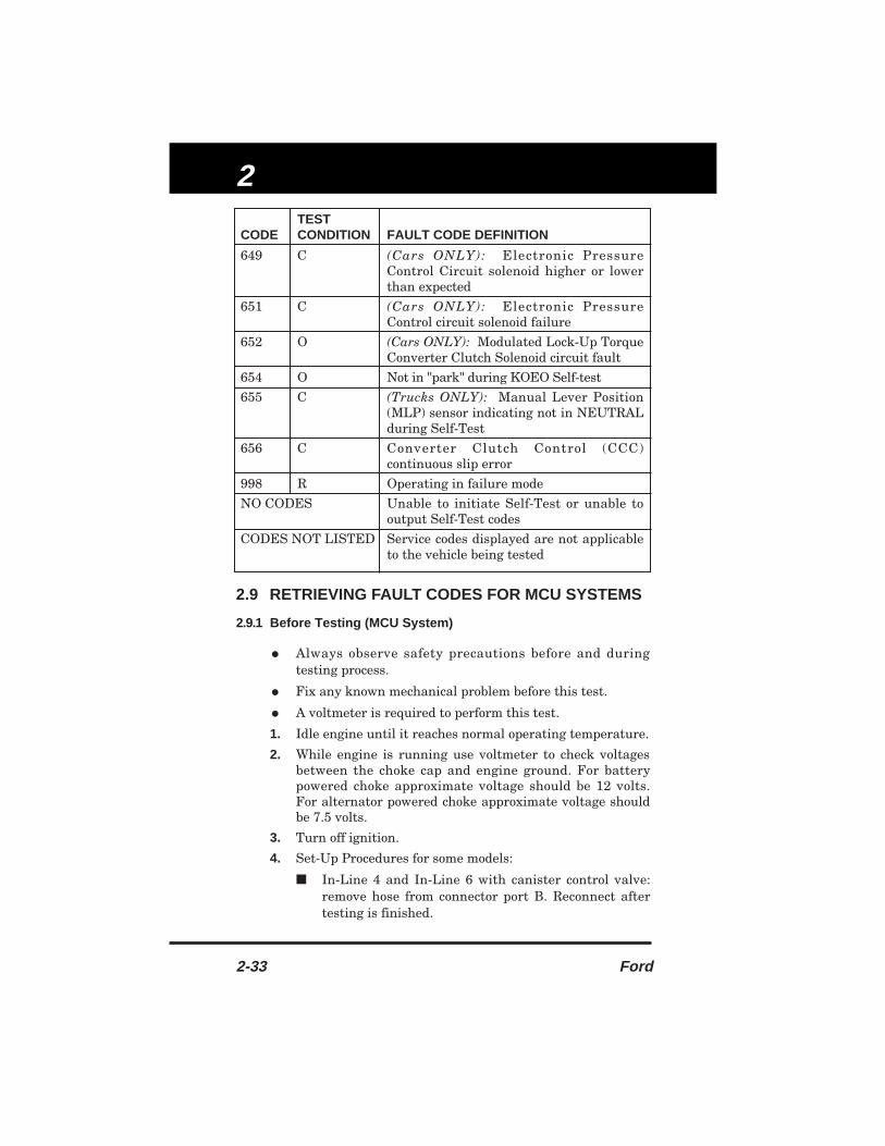
2.9 RETRIEVING FAULT CODES FOR MCU SYSTEMS
2.9.1 Before Testing (MCU System)
• Always observe safety precautions before and duringtesting process.
• Fix any known mechanical problem before this test.
• A voltmeter is required to perform this test.
1. Idle engine until it reaches normal operating temperature.
2. While engine is running use voltmeter to check voltagesbetween the choke cap and engine ground. For batterypowered choke approximate voltage should be 12 volts.For alternator powered choke approximate voltage shouldbe 7.5 volts.
3. Turn off ignition.
4. Set-Up Procedures for some models:
■ In-Line 4 and In-Line 6 with canister control valve:remove hose from connector port B. Reconnect aftertesting is finished.
2-33 Ford
TESTCODE CONDITION FAULT CODE DEFINITION
649 C (Cars ONLY): Electronic PressureControl Circuit solenoid higher or lowerthan expected
651 C (Cars ONLY): Electronic PressureControl circuit solenoid failure
652 O (Cars ONLY): Modulated Lock-Up TorqueConverter Clutch Solenoid circuit fault
654 O Not in "park" during KOEO Self-test
655 C (Trucks ONLY): Manual Lever Position(MLP) sensor indicating not in NEUTRALduring Self-Test
656 C Converter Clutch Control (CCC)continuous slip error
998 R Operating in failure mode
NO CODES Unable to initiate Self-Test or unable tooutput Self-Test codes
CODES NOT LISTED Service codes displayed are not applicableto the vehicle being tested

ECM
Ford 2-34
■
V-6 and V-8: remove PCV valve. Reconnect aftertesting is finished.
■ 2.3L with GK code: locate the anti-backfire vacuumswitch tee behind the MCU module and remove thecap. Reconnect after testing is finished.
■ 2.3L with EGR vacuum load control valve: covervacuum valve vent holes with tape. Remove the tapeafter testing is finished.
■ 4.2L with vacuum delay valve: uncap restrictor inThermactor Air Diverter (TAD) solenoid vacuum line.Reconnect after testing is finished.
■ 5.8L with vacuum delay valve: uncap restrictor inThermactor Air Bypass (TAB) solenoid vacuum line.Reconnect after testing is finished.
2.9.2 (KOEO) Key On Engine Off Test (MCU System)
• Always observe safety precautions before and duringtesting process.
•
ALWAYS check Code Reader battery before retrievingfault codes.
• "Before Testing" procedures (paragraph 2.9.1) must beperformed before this test.
1. Turn off ignition.
2. Set Code Reader switch toHOLD and connect to thevehicle test connector (no singlepin connection).
3. Set Code Reader Switch toTEST.
4. Turn on ignition, DO NOTSTART THE ENGINE.
5. Read codes on LED. If LED does not blink, check CodeReader battery and repeat KOEO Test. If LED still doesnot blink, refer to vehicle's service manual troubleshootingsection. Count blinks to get service codes. All codes aretwo digits long.
■ Code 22 looks like:
BLINK BLINK
PAUSE
BLINK BLINK
= Code 22
FORDCODE
READERO F F
AUDIOON
HOLD
TEST
E C M • A B S
FORDCODE
READERO F F
AUDIOON
HOLD
TEST
E C M • A B S

2
2-35 Ford
6. Turn off ignition and remove the Code Reader.
2.9.3 (KOER) Key On Engine Running Test (MCU System)
NOTE:
For vehicles with 2.3L HSC engines: Locate vacuumtee and restrictor in the thermactor vacuum controlline, and uncap during KOER Test.
• Always observe safety precautions before and duringtesting process.
• ALWAYS check Code Reader battery before retrievingfault codes.
• "Before Testing" procedures (paragraph 2.9.1) and "KOEOTest" (paragraph 2.9.2) must be performed before this test.
A. For In-Line 4 And In-Line 6 Engines1. Turn off ignition.
2. Set Code Reader switch toHOLD and connect code readerto the vehicle test connector (nosingle pin connection).
3. Set Code Reader switch toTEST.
4. Start engine.
5. Gradually increase engine speed to 3,000 RPMs and holdthrough step 7.
6. Read Engine ID Code on LED. The number of blinksindicates the number of cylinders in your engine. Continueholding RPM until code pulses begin.
7. Return engine speed to idle when codes begin.
8. Turn off ignition and remove Code Reader.
B. For V-6 And V-8 Engines
1. Turn off ignition.
2. Set Code Reader Switch toHOLD and connect to thevehicle test connection (nosingle pin connection).
FORDCODE
READERO F F
AUDIOON
HOLD
TEST
E C M • A B S
BLINK BLINK
= 4 CylindersBLINK
= 6 CylindersBLINK BLINK
FORDCODE
READERO F F
AUDIOON
HOLD
TEST
E C M • A B S
FORDCODE
READERO F F
AUDIOON
HOLD
TEST
E C M • A B S
ECM
Ford 2-36
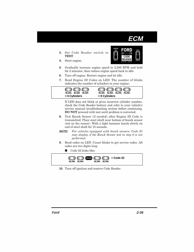
3. Set Code Reader switch toTEST.
4. Start engine.
5. Gradually increase engine speed to 2,500 RPM and holdfor 2 minutes, then reduce engine speed back to idle.
6. Turn off engine. Restart engine and let idle.
7. Read Engine ID Codes on LED. The number of blinksindicates the number of cylinders in your engine:
If LED does not blink or gives incorrect cylinder number,check the Code Reader battery and refer to your vehicle'sservice manual troubleshooting section before continuing.DO NOT proceed with test until problem is corrected.
8. Test Knock Sensor (if needed) after Engine ID Code istransmitted. Place steel shaft near bottom of knock sensor(not on the sensor). With a light hammer knock slowly onend of steel shaft for 15 seconds.
NOTE: For vehicles equipped with knock sensors: Code 25may display if the Knock Sensor test in step 8 is notperformed.
9. Read codes on LED. Count blinks to get service codes. Allcodes are two digits long.
■ Code 22 looks like:
10. Turn off ignition and remove Code Reader.
BLINK BLINK
PAUSE
BLINK BLINK
= Code 22
FORDCODE
READERO F F
AUDIOON
HOLD
TEST
E C M • A B S
BLINK BLINK BLINK
= 6 CylindersBLINK BLINK
= 8 CylindersBLINK BLINK

2
2-37 Ford
2.10 FAULT CODE DEFINITIONS FOR MCU SYSTEMS /CAR & TRUCK
CODE FAULT CODE DEFINITION
11 NOTE: "High Altitude" refers to vehicles computeradjusted for high elevations.
I-4 (All except High Altitude): System OKI-4 (High Altitude only): Altitude (ALT) circuit is open.I-6: System OK.V-6 (All except High Altitude): System OK.V-6 (High Altitude only): Altitude (ALT) circuit is open.V-8 (All except High Altitude): System OK.V-8 (High Altitude only): Altitude (ALT) circuit is open.
12 V-8: RPM out of range (throttle kicker).
25 V-8: Knock Sensor (KS) signal not detected.
33 I-4, I-6, V-6: Key On Engine Running (KOER) Self-Testnot initiated.
41 All Engines: Exhaust Gas Oxygen sensor: voltagesignal lean (low).
42 All Engines: Exhaust Gas Oxygen sensor: voltagesignal rich (high).
44 All Engines: Oxygen sensor signal indicates Rich -excessive fuel, restricted air intake — or — InoperativeThermactor System
45 All Engines: Thermactor air flow going upstream toexhaust manifold.
46 All Engines: Thermactor Air System unable to bypass.
51 I-4: Low or Mid Temperature Switch is open whenengine is hot.I-6: Low or Mid Temperature Vacuum Switch is openwhen engine is hot.V-6: Hi or Hi/Low Vacuum Switch is always open.V-8: Hi or Hi/Low Vacuum Switch is always open.
52 I-4 (car): Idle Tracking Switch (ITS) - voltage does notchange from closed to open throttle.I-4 (truck): Idle/Decel Vacuum Switch open constantly.I-6: Wide Open Throttle Vacuum Switch is openconstantly.

ECM
Ford 2-38
CODE FAULT CODE DEFINITION
53 I-4: Wide Open Throttle Vacuum Switch openconstantly.I-6: CROWD Vacuum Switch open constantly.V-6: Dual Temperature Switch is open constantly.V-8: Dual Temperature Switch is open constantly.
54 V-8: Mid Temperature Switch is open constantly.
55 V-8: Mid Vacuum Switch is open constantly.
56 I-6: Closed Throttle Vacuum Switch is open constantly.
61 V-8: Hi/Low Vacuum Switch is closed constantly.
62 NOTE: "High Altitude" refers to vehicles computeradjusted for operation at high elevations.
I-4 (car): Idle Tracking Switch is closed at idle.I-4 (truck): Idle/Decel Vacuum Switch is closedconstantly.I-6: Wide Open Throttle Vacuum Switch is closedconstantly.V-6 (All except High Altitude): Altitude circuit is open.V-6 (High Altitude only): System OK.V-8 (All except High Altitude): Altitude (ALT) circuit isopen.V-8 (High Altitude only): System OK.
63 I-4: Wide Open Throttle Vacuum Switch is closedconstantly.I-6: CROWD Vacuum Switch is closed constantly.
64 NOTE: "High Altitude" refers to vehicles that arecomputer adjusted for high elevation operation.
I-4: (All except High Altitude): Altitude circuit is open.I-4: (High Altitude only): System OK.V-6: Mid Vacuum Switch is closed constantly.V-8: Mid Vacuum Switch is closed constantly.
65 NOTE: "High Altitude" refers to vehicles that arecomputer adjusted for high elevation operation.
I-4: (All except High Altitude): Altitude circuit is open.I-4: (High Altitude Only): System OK.V-6: Mid Vacuum Switch is closed constantly.V-8: Mid Vacuum Switch is closed constantly.
66 I-6: Closed Throttle Vacuum Switch is closedconstantly.
3
3-1 Ford
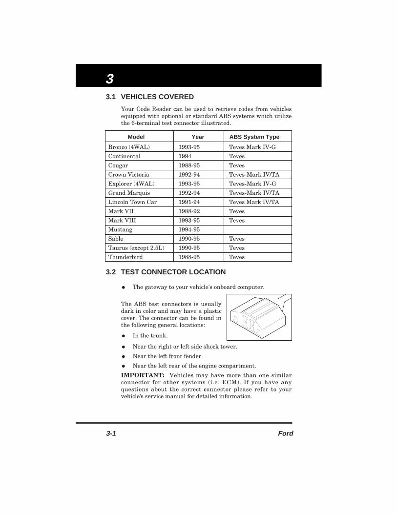
3.1 VEHICLES COVERED
Your Code Reader can be used to retrieve codes from vehiclesequipped with optional or standard ABS systems which utilizethe 6-terminal test connector illustrated.
3.2 TEST CONNECTOR LOCATION
• The gateway to your vehicle's onboard computer.
The ABS test connectors is usuallydark in color and may have a plasticcover. The connector can be found inthe following general locations:
• In the trunk.
• Near the right or left side shock tower.
• Near the left front fender.
• Near the left rear of the engine compartment.
IMPORTANT: Vehicles may have more than one similarconnector for other systems (i.e. ECM). If you have anyquestions about the correct connector please refer to yourvehicle's service manual for detailed information.
Model Year ABS System Type
Bronco (4WAL) 1993-95 Teves Mark IV-G
Continental 1994 Teves
Cougar 1988-95 Teves
Crown Victoria 1992-94 Teves-Mark IV/TA
Explorer (4WAL) 1993-95 Teves-Mark IV-G
Grand Marquis 1992-94 Teves-Mark IV/TA
Lincoln Town Car 1991-94 Teves Mark IV/TA
Mark VII 1988-92 Teves
Mark VIII 1993-95 Teves
Mustang 1994-95
Sable 1990-95 Teves
Taurus (except 2.5L) 1990-95 Teves
Thunderbird 1988-95 Teves
ABS
Ford 3-2
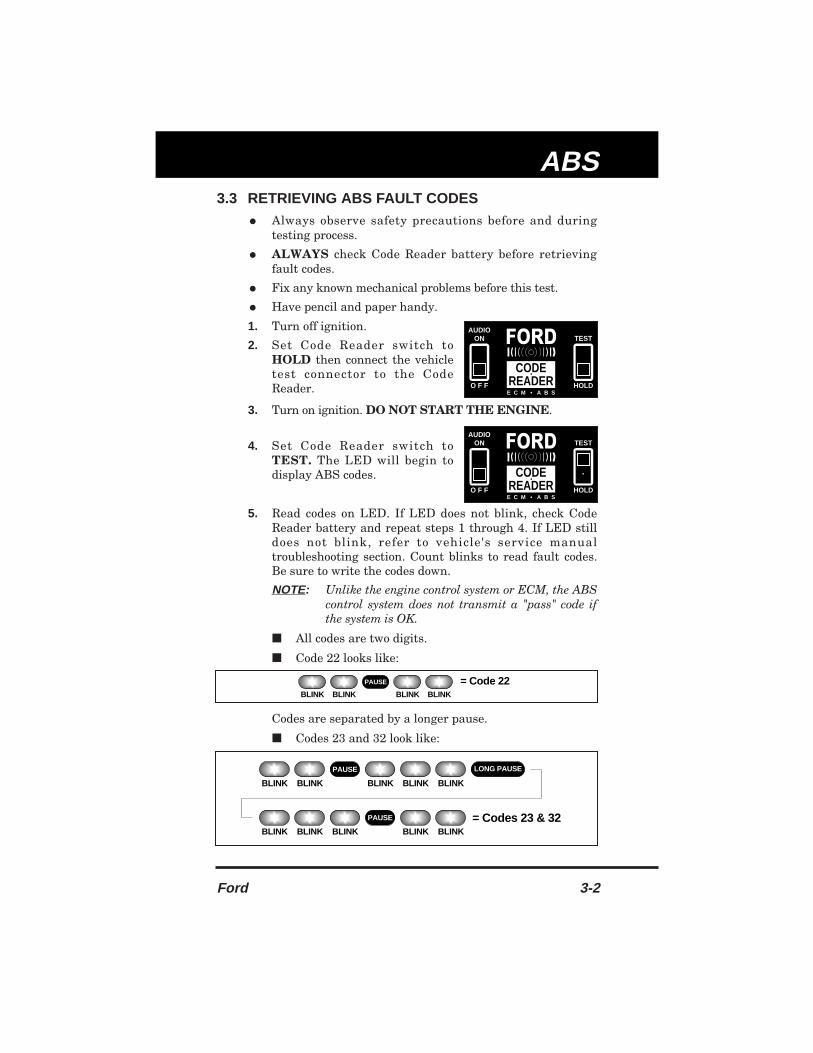
3.3 RETRIEVING ABS FAULT CODES
• Always observe safety precautions before and duringtesting process.
• ALWAYS check Code Reader battery before retrievingfault codes.
• Fix any known mechanical problems before this test.
• Have pencil and paper handy.
1. Turn off ignition.
2. Set Code Reader switch toHOLD then connect the vehicletest connector to the CodeReader.
3. Turn on ignition. DO NOT START THE ENGINE.
4. Set Code Reader switch toTEST. The LED will begin todisplay ABS codes.
5. Read codes on LED. If LED does not blink, check CodeReader battery and repeat steps 1 through 4. If LED stilldoes not blink, refer to vehicle's service manualtroubleshooting section. Count blinks to read fault codes.Be sure to write the codes down.
NOTE:
Unlike the engine control system or ECM, the ABScontrol system does not transmit a "pass" code ifthe system is OK.
■ All codes are two digits.
■ Code 22 looks like:
Codes are separated by a longer pause.
■ Codes 23 and 32 look like:
FORDCODE
READERO F F
AUDIOON
HOLD
TEST
E C M • A B S
FORDCODE
READERO F F
AUDIOON
HOLD
TEST
E C M • A B S
BLINK BLINK
PAUSE
BLINK BLINK
= Code 22
BLINK BLINK
BLINK BLINK= Codes 23 & 32
BLINK
BLINK BLINKBLINK
PAUSE
BLINKBLINK
PAUSE
LONG PAUSE

3
3-3 Ford
6. Turn off ignition and remove the Code Reader.
NOTES
: Fault codes 21 through 29 MUST be servicedand erased before any other codes can berecorded or retrieved.
If code 61 appears with any other code, disregardit. If code 61 appears by itself, service code 61.
3.4 ERASING ABS CODES
• Always observe safety precautions before and duringtesting process.
• Erase codes only when repairs have been completed.1. Drive vehicle at a speed greater than 25 MPH for two or
three minutes. Stored codes should be cleared.
2. If codes are not cleared, repeat steps 1 through 6 ofparagraph 3.3 to check for additional stored codes.
3. Repeat steps 1 and 2, above, as necessary until all codeshave been retrieved and memory has been cleared.
NOTE: All fault codes must be retrieved before memorycan be cleared.
3.5 ABS FAULT CODE DEFINITIONS
3.5.1 ABS fault code definitions for Bronco and Explorer (1993-95)ONLY
• Consult your vehicle's service manual for detailedmeaning related to your vehicle.
CODE FAULT CODE DEFINITION
11 Electronic Controller (EBCM)
16 System OK
17 Reference Voltage
22 Left Front Inlet Valve
23 Left Front Outlet Valve
24 Right Front Inlet Valve
25 Right Front Outlet Valve
26 Rear Axle Inlet Valve
27 Rear Axle Outlet Valve
31 Left Front Wheel Sensor
32 Right Front Wheel Sensor
ABS
Ford 3-4
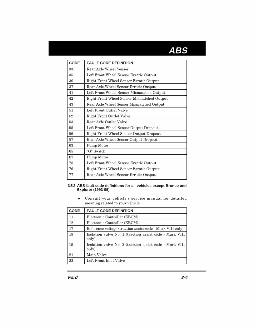
3.5.2 ABS fault code definitions for all vehicles except Bronco andExplorer (1993-95)
• Consult your vehicle's service manual for detailedmeaning related to your vehicle.
CODE FAULT CODE DEFINITION
33 Rear Axle Wheel Sensor
35 Left Front Wheel Sensor Erratic Output
36 Right Front Wheel Sensor Erratic Output
37 Rear Axle Wheel Sensor Erratic Output
41 Left Front Wheel Sensor Mismatched Output
42 Right Front Wheel Sensor Mismatched Output
43 Rear Axle Wheel Sensor Mismatched Output
51 Left Front Outlet Valve
52 Right Front Outlet Valve
53 Rear Axle Outlet Valve
55 Left Front Wheel Sensor Output Dropout
56 Right Front Wheel Sensor Output Dropout
57 Rear Axle Wheel Sensor Output Dropout
63 Pump Motor
65 "G" Switch
67 Pump Motor
75 Left Front Wheel Sensor Erratic Output
76 Right Front Wheel Sensor Erratic Output
77 Rear Axle Wheel Sensor Erratic Output
CODE FAULT CODE DEFINITION
11 Electronic Controller (EBCM)
12 Electronic Controller (EBCM)
17 Reference voltage (traction assist code - Mark VIII only)
18 Isolation valve No. 1 (traction assist code - Mark VIIIonly)
19 Isolation valve No. 2 (traction assist code - Mark VIIIonly)
21 Main Valve
22 Left Front Inlet Valve

3
3-5 Ford
CODE FAULT CODE DEFINITION
23 Left Front Outlet Valve
24 Right Front Inlet Valve
25 Right Front Outlet Valve
26 Rear Inlet Valve
27 Rear Outlet Valve
28 Left Rear Inlet Valve
29 Left Rear Outlet Valve
31 Left Front Wheel Sensor
32 Right Front Wheel Sensor
33 Right Rear Wheel Sensor
34 Left Rear Wheel Sensor
35 Left Front Wheel Sensor Erratic Output
36 Right Front Wheel Sensor Erratic Output
37 Right Rear Wheel Sensor Erratic Output
38 Left Rear Wheel Sensor Erratic Output
41 Left Front Wheel Sensor Mismatched Output
42 Right Front Wheel Sensor Mismatched Output
43 Right Rear Wheel Sensor Mismatched Output
44 Left Rear Wheel Sensor Mismatched Output
45 Left Front and One Other Wheel Sensor
46 Right Front and One Other Wheel Sensor
47 Missing Rear Wheel Sensor
48 Missing Three or Four Wheel Sensor
51 Left Front Outlet Valve
52 Right Front Outlet Valve
53 Right Rear Outlet Valve
54 Left Rear Outlet Valve
55 Left Front Wheel Sensor Output Dropout
56 Right Front Wheel Sensor Output Dropout
57 Right Rear Wheel Sensor Output Dropout
58 Left Rear Wheel Sensor Output Dropout
61 Fluid Level Indicator and Pressure Warning SwitchCircuit
62 Pedal Travel Switch
63 Pump Motor Speed Sensor

ABS
Ford 3-6
CODE FAULT CODE DEFINITION
64 Pump Motor Pressure
67 Pump Motor Relay (traction assist code - Mark VIIIonly)
71 Left Front Wheel Sensor
72 Right Front Wheel Sensor
73 Right Rear Wheel Sensor
74 Left Rear Wheel Sensor
75 Left Front Wheel Sensor Erratic Output
76 Right Front Wheel Sensor Erratic Output
77 Right Rear Wheel Sensor Erratic Output
78 Left Rear Wheel Sensor Erratic Output
88 Electronic Controller (EBCM)
99 Electronic Controller (EBCM)

4
4-1 Ford
4.1 INTRODUCTION
The Society of Automotive Engineers has issued a Standard(SAE J1930) for Electrical/Electronic Systems DiagnosticTerms, Definitions, Abbreviations, and Acronyms. However, atthe present time, this Standard is not in wide use by vehiclemanufacturers.
This Glossary contains definitions for abbreviations and termsyou may find in this manual or in your vehicle service manual.These definitions
may not agree with those contained in SAEJ1930.
4.2 GLOSSARY OF TERMS AND ABBREVIATIONS
4EAT – Ford electronic automatic 4 speed transaxle.
A/C – Air Conditioning.
A4LD – Ford automatic 4 speed lock-up converter drive.
AAC – Auxiliary Air Control Valve.
ABS – Anti-Lock Brake System.
ACC – Air Conditioning Clutch compressor signal input tocomputer relating status of air conditioning clutch.
ACCS – Air Conditioning Cycling Switch.
ACD – Air Conditioner Demand switch.
ACT – Air Charge Temperature sensor or signal circuit.
ACV – (Thermactor) Air Control Valve.
AIR – Secondary air injection (formerly thermactor).
AIR BPV – Thermactor Air Bypass Valve.
AM1 – Thermactor Air Management (TAB).
AM2 – Thermactor Air Management (TAD).
AMBIENT TEMPERATURE – Temperature of airsurrounding vehicle being serviced.
ANTI-BFV – Anti-Backfire Valve.
AOD – Automatic Over Drive transmission.
ATDC – After Top Dead Center.
AVOM – Analog Volt/Ohm Meter.
AXOD – Automatic Overdrive transaxle.
AXOD-E – Automatic Overdrive transaxle, electronicallycontrolled.
BAC – Bypass Air Control valve.
BARO – Barometric Pressure.

Glossary
Ford 4-2
BASE IDLE – Idle RPM when the throttle lever rests on thethrottle stop and the Idle Speed Control is fully retracted anddisconnected.
BCM – Body Computer Module.
BOO – Brake On-Off input to the computer.
BOOST – Condition of over-pressure (above atmospheric) inthe intake manifold; caused by intake air being forced in by aturbocharger or supercharger.
BP – Barometric Pressure sensor. Used to compensate foraltitude variations.
BPA – ByPass Air solenoid.
BTDC – Before Top Dead Center.
BVT – Back-pressure Variable Transducer.
CANISTER – A container, in an evaporative emission system,that contains charcoal to trap fuel vapors from the fuel system.
CANISTER PURGE SOLENOID – Electrical solenoid or itscontrol line. Solenoid opens a valve from fuel vapor canisterline to intake manifold when energized. Controls flow ofvapors between carburetor bowl vent and carbon canister.
CANP – Canister Purge solenoid.
CATALYTIC CONVERTER – Muffler like assembly placedin exhaust system that contains a catalyst to changehydrocarbons and carbon monoxide into water vapor andcarbon dioxide.
CCC – Converter Clutch Control solenoid or its circuit.
CCD – Computer Controlled Dwell, used on Ford Vehicles.
CCO – Converter Clutch Override output from the computerprocessor to the transmission.
CCS – Coast Clutch Solenoid or its circuit.
CENTRAL FUEL INJECTION – Computer control fuelinjection at throttle body, used on Fords, same as throttle bodyinjection.
CER – Cold Enrichment Rod.
CES – Clutch Engage Switch.
CFI – Central Fuel Injection.
CHECK ENGINE LIGHT – Dash panel light used either toaid in identification and diagnosis of a system problems or toindicate that maintenance is required.
CHECK VALVE – Valve that operates like a one-way gate.
CID – Cylinder Identification sensor or its circuit.

4
4-3 Ford
CKT – Circuit.
CL – Closed Loop.
CLC – Converter Lock-up Clutch.
CO – Carbon Monoxide.
COC – Conventional Oxidation Catalyst.
COMPUTER TIMING –Total spark advance in degreesbefore top dead center. Calculated by Ford EEC-IV processor,based on sensor input.
CONTINUOUS SELF-TEST – Continuous test of Ford EEC-IV system conducted whenever vehicle is in operation.
CPS – Crankshaft Position Sensor. Provides the ECU withengine speed and crankshaft angle (position).
CTS – Coolant Temperature Sensor.
CURB IDLE – Computer controlled idle rpm.
CVR – Control Vacuum Regulator.
CWM – Cold Weather Modulator.
CYLINDER IDENTIFICATION SIGNAL (CID) – A signalgenerated by crankshaft timing sensor, used to synchronizeignition coils, due to the fact that some models use a 2 ignitioncoil pack DIS system.
C3I – Computer Controlled Coil Ignition. Produces ignitionspark without aid of an ignition distributor.
DCL – Data Communications Link.
DERM – Diagnostic Energy Reserve Module and air bag (SIR)controller.
DFS – Decel Fuel Shut-off.
DIC – Driver Information Center.
DID – Driver Information Display.
DIS – Direct Ignition System. Produces ignition spark withoutaid of an ignition distributor. (Similar to C3I).
DOL – Data Output Link. Fuel calculation data from EEC-IVprocessor to trip computer.
DPDIS – Dual Plug Distributorless Ignition System, used onsome Ford 2.3L engines.
DPI – Dual Plug Inhibit, used on some Ford 2.3L engines.
DUAL CATALYTIC CONVERTER – Combines 2 convertersin one shell. Controls NOx, HC and CO. Also called TWC.
DURA SPARK SYSTEM – The Ford ignition system usedwith the 5.8L feedback carbureted MCU control system.

Glossary
Ford 4-4
DV TW – Delay Valve, 2 Way.
DVM (10 MEG) – Digital voltmeter with a minimum of 10million ohms resistance. Allows measurement in circuitwithout affecting the circuit operation.
DWELL – Amount of time (recorded on a dwell meter indegrees) that current passes through a closed switch.
E4OD – Ford Electronic 4 speed Overdrive transmission.
EAS – Electronic Air Switching, directs airflow to catalyticconverter or exhaust ports of the engine.
EBCM – Electronic Brake Control Module.
ECA – Electronic Control Assembly. Ford’s engine controllingcomputer.
ECM – Engine Control Module properly call a PowertrainControl Module.
ECT – Engine Coolant Temperature sensor or circuit.
ECU – Electronic Control Unit. To process input informationto trigger ignition control module.
EDF – Electro-Drive Fan relay or its circuit.
EEC-IV – Electronic Engine Control design 4. A computercontrolled system of engine control used on Ford.
EECS – Evaporative Emission Control System.
EEGR – Electronic Exhaust Gas Recirculation valve (Sonic).
EEPROM – Electronically Erasable Programmable Read OnlyMemory.
EET – Electronic Exhaust Gas Recirculation Transducer.
EFC – Electronic Feedback Carburetor. Utilizes an electronicsignal, generated by an exhaust gas oxygen sensor to preciselycontrol air/fuel mixture ratio in the carburetor.
EFI – Electronic Fuel Injection. Computer controlled fuelinjection system. On Ford EFI uses injectors in each intakeport and CFI uses an injector in the throttle body.
EGO – Exhaust Gas Oxygen sensor.
EGR – Exhaust Gas Recirculation system is designed to allowflow of inert exhaust gases into combustion chamber to coolcombustion and reduce nitrous oxides in exhaust.
EHC – Exhaust Heat Control vacuum solenoid or its circuit.
EIC – Electronic Instrument Cluster.
ELECTRONIC SPARK CONTROL – Used to retard sparkadvance if detonation occurs.

4
4-5 Ford
ELECTRONIC SPARK TIMING – PCM controlled timing ofthe ignition spark.
EMR – Electronic Module Retard, controls spark retard.
ENGINE CONTROL MODULE – A microprocessor baseddevice which contains electronic circuitry to control andmonitor air/fuel and emission systems, and aid in diagnostics.
EPC – Electronic Pressure Control solenoid.
EPROM – Erasable Programmable Read Only Memory.
ER – Engine running, used on some Ford system tests.
ERS – Engine RPM Sensor.
ESA – Electronic Spark Advance.
ESC – Electronic Spark Control.
EST – Electronic Spark Timing.
EVP – EGR Valve Position sensor or its circuit.
EVR – EGR Vacuum Regulator or its circuit.
EVRV – Electronic Vacuum Regulator Valve. Controls EGRvacuum.
EXHAUST GAS OXYGEN SENSOR – Sensor that changesits voltage output as exhaust gas oxygen content changes ascompared to oxygen content of the atmosphere. The constantlychanging electrical signal is used to control fuel mixture.
EXHAUST GAS RECIRCULATION – Procedure where asmall amount of exhaust gas is readmitted to combustionchamber to reduce peak combustion temperatures, thusreducing NOx.
FAIL SAFE – or Fail Soft: any attempt by a computer tocompensate for a fault or lost signal, usually by substitutingfixed replacement valves.
FEEDBACK CARBURETOR (FBC) – System of fuel controlemploying a computer controlled solenoid that varies thecarburetors air/fuel mixture.
FEEDBACK CARBURETOR ACTUATOR – Computercontrolled stepper motor used on Ford feedback carburetors,that varies air/fuel mixture.
FMEM – Failure Mode Effects Management. Sometimesreferred to limp-in mode.
FTO – Filter Tach Output. An output from Ford DIS TFI IVmodule which provides a filtered ignition signal to theprocessor in order to control dwell.

Glossary
Ford 4-6
GND, GRD or GRND – Ground. Common line leading to thenegative side of the battery.
HALL EFFECT –Process where current is passed through asmall slice of semiconductor material at the same time as amagnetic field to produce a small voltage in the semiconductor.
HARD FAULT – Fault present during current engineoperating cycle. Opposite of an intermittent fault which doesnot stay present.
HBV – Heater Blower Voltage input to EEC-IV processorreflecting heater blower voltage demand.
HEDF – High-speed Electro-Drive Fan relay or its circuit.
HEGO – Heated Oxygen Sensor or its circuit.
HIC – Hot Idle Compensator.
IAC – Idle Air Control.
IAS – Inlet Air Solenoid valve or its circuit.
IAT – Intake air temperature sensor, performs same functionas MAT sensor.
ICM – Integrated Control Module.
IDLE TRACKING SWITCH – An input device that sends asignal to the computer to indicate a closed throttle condition.
IDM – Ignition Diagnostics Monitor. Continuous monitor ofignition input to EEC-IV processor used to detect intermittentignition faults.
IGN – Ignition.
INTERMITTENT FAULT – Fault which occurred during aprevious engine operating cycle. Intermittent fault may haveset a fault code which is still present in PCM memory.
IRCM – Integrated Relay Control Module, used on some Fordsystems.
ISA – Idle Speed Actuator. Extends or retracts to controlengine idle speed and to set throttle stop angle duringdeceleration.
ISC – Idle Speed Control, either computer control motor, airbypass valve, or any device used to control idle rpm.
ITS – Idle Tracking Switch.
KAM – Keep Alive Memory. Battery power memory locationsin computer used to store failure codes and some diagnosticparameters.
KAPWR – Keep Alive Power, used to power KAM circuit ofthe processor.
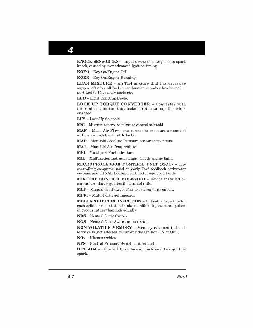
4
4-7 Ford
KNOCK SENSOR (KS) – Input device that responds to sparkknock, caused by over advanced ignition timing.
KOEO – Key On/Engine Off.
KOER – Key On/Engine Running.
LEAN MIXTURE – Air/fuel mixture that has excessiveoxygen left after all fuel in combustion chamber has burned, 1part fuel to 15 or more parts air.
LED – Light Emitting Diode.
LOCK UP TORQUE CONVERTER – Converter withinternal mechanism that locks turbine to impeller whenengaged.
LUS – Lock-Up Solenoid.
M/C – Mixture control or mixture control solenoid.
MAF – Mass Air Flow sensor, used to measure amount ofairflow through the throttle body.
MAP – Manifold Absolute Pressure sensor or its circuit.
MAT – Manifold Air Temperature.
MFI – Multi-port Fuel Injection.
MIL – Malfunction Indicator Light. Check engine light.
MICROPROCESSOR CONTROL UNIT (MCU) – Thecontrolling computer, used on early Ford feedback carburetorsystems and all 5.8L feedback carburetor equipped Fords.
MIXTURE CONTROL SOLENOID – Device installed oncarburetor, that regulates the air/fuel ratio.
MLP – Manual (shift) Lever Position sensor or its circuit.
MPFI – Multi-Port Fuel Injection.
MULTI-PORT FUEL INJECTION – Individual injectors foreach cylinder mounted in intake manifold. Injectors are pulsedin groups rather than individually.
NDS – Neutral Drive Switch.
NGS – Neutral Gear Switch or its circuit.
NON-VOLATILE MEMORY – Memory retained in blocklearn cells (not affected by turning the ignition ON or OFF).
NOx – Nitrous Oxides.
NPS – Neutral Pressure Switch or its circuit.
OCT ADJ – Octane Adjust device which modifies ignitionspark.

Glossary
Ford 4-8
OXYGEN SENSOR – Sensor that changes its voltage outputas exhaust gas oxygen content changes as compared to theoxygen content of the atmosphere. The constantly changingelectrical signal is used to control fuel mixture.
PCM – Powertrain Control Module. Computer that controlsengine fuel, ignition and emission related functions.
PCV – Positive Crankcase Ventilation. System that controlsflow of crankshaft vapors into engine intake manifold wherethey are burned in combustion rather then being dischargedinto the atmosphere.
PFE – Pressure Feedback EGR sensor or its circuit.
PFI – Port Fuel Injection.
PIP – Profile Ignition Pickup.
PORTED VACUUM SWITCH – Temperature actuatedswitch that changes vacuum connections when the coolanttemperature changes.
POT – Potentiometer.
POWERTRAIN CONTROL MODULE – Same as ECM, butalso controls electronically controlled automatic transmission.
PROFILE IGNITION PICKUP – A Hall effect vane switchthat furnishes crankshaft position data to the EEC-IVprocessor.
PROM – Programmable Read Only Memory.
PSPS – Power Steering Pressure Switch. Signal is used bycomputer to compensate for power steering loads.
PVS – Ported Vacuum Switch.QUICK TEST – A functional diagnostic test for Ford EEC-IVsystem, consisting of test hookup, key on engine off, enginerunning and continuous self test models.RAP – Retained Accessory Power.RELAY – Switching device operated by a low current circuit,which controls opening and closing of another higher currentcircuit.RELIEF VALVE – Pressure limiting valve located in exhaustchamber of thermactor air pump. Relieves part of exhaustairflow if pressure exceeds a calibrated value.RICH MIXTURE – Air/fuel mixture that has more fuel thancan burn completely, 1 part fuel to 14 or less parts air.SAW – Spark Advance Word, and also Spark Angle Word.SCC – Spark Control Computer.

4
4-9 Ford
SEFI – Sequential Electronic Fuel Injection. Injectors locatedin intake ports that inject fuel triggered by ignition timing.SELF-TEST – One of 3 subsets of Ford EEC-IV quick testmodes.
SES – Service Engine Soon light.
SFI – Sequential Fuel Injection,type of MFI with injectorspulsed individually based on engine firing order.
SIG RTN – Signal Return circuit for all sensors except HEGO.
SIL – Shift Indicator Light. Indicates to driver optimum timeto shift gears.
SIR – Supplemental Inflatable Restraint (SIR) system; airbag.
SIS – Solenoid Idle Stop.
SOLENOID – Wire coil with a movable core which changesposition by means of electromagnetism when current flowsthrough the coil.
SPARK RETARD SOLENOID – Output device that receivesan output signal from Ford MCU system to bleed distributor’svacuum advance when spark knock occurs.
SPOUT – Spark output signal from EEC-IV processor to TFI-IV module, used to control amount of timing retard.
SSI – Solid State Ignition system.
STI – Self Test Input (Ford) circuit in EEC or MCU systems.Used to place computer into testing mode.
STO – Self Test Output (Ford) circuit in EEC or MCUsystems. Used by computer to send testing and fault codes totester.
T.V. – Throttle Valve.
TAB – Thermactor Air Bypass solenoid.
TACH INPUT – Engine rpm signal sent to computer fromignition coil primary circuit.
TAD – Thermactor Air Diverter solenoid.
TBI – Throttle Body Injection (Fuel).
TCC – Torque Converter Clutch.
TCP – Temperature Compensating Pump.
TDC – Top Dead Center.
TFI – Thick Film Ignition module. Controls coil and ignitionoperation on most Ford vehicles.

Glossary
Ford 4-10
THERMACTOR AIR BYPASS SOLENOID – Solenoidswitches engine manifold vacuum. Vacuum reacts onthermactor bypass valve to bypass thermactor air to theatmosphere. Used on Ford MCU feedback carburetor system.
THERMACTOR AIR CONTROL VALVE – Combinesfunction of a normally closed air bypass valve and an airdiverter valve in one integral valve.
THERMACTOR AIR DIVERTER SOLENOID – Solenoidswitches engine manifold vacuum. Vacuum switchesthermactor air from downstream (past EGO sensor) toupstream (before EGO sensor) when solenoid is energized.Used on Ford MCU feedback carburetor system.
THERMACTOR AIR SYSTEM – Efficiency of catalyticconverter is dependent upon temperature and chemicalmakeup of exhaust gases. These requirements are met by thethermactor air supply system.
THREE-WAY CATALYST – Combines 2 converters in 1shell. Controls NOx, HC and CO. Also called dual catalyticconverter.
TIMING – Relationship between spark plug firing and pistonposition.
TK – Throttle Kicker solenoid, when energized, suppliesmanifold vacuum to throttle kicker actuator as directed bycomputer to compensate for engine loads. Also called idle-upsystem.
TOT – Transmission Oil Temperature sensor.
TP – Throttle Position sensor or its circuit. Used to signalcomputer the position of the throttle plates.
TPI – Tuned Port Injection, a type of MFI with intake tubesdesigned to be tuned for performance. Most TPI engines arealso SFI.
TTS – Transmission Temperature Switch.
TVS – Temperature Vacuum Switch.
TVV – Thermal Vent Valve.
TWC – Three-Way Catalyst.
VACUUM – A term to describe a pressure that is less thanatmospheric pressure.
VACUUM ADVANCE – Advances ignition timing withrelation to engine load or computer signals.
VAF – Vane Air-Flow sensor or its circuit.
VAT – Vane Air-Flow Temperature sensor.

4
4-11 Ford
VM – Vane Meter or air flow meter.
VSS – Vehicle Speed Sensor.
WOT – Wide Open Throttle or Wide Open Throttle switch.
ZONED VACUUM SWITCHES – 3 switches used on FordMCU system that provides input signals to MCU, regardingengine load.

Glossary
Ford 4-12

5
5-1 Ford
5.1 LIMITED ONE YEAR WARRANTY
The Manufacturer warrants to the original purchaser that thisunit is free of defects in materials and workmanship undernormal use and maintenance for a period of one (1) year fromthe date of original purchase.
If the unit fails within the one (1) year period, it will berepaired or replaced, at the Manufacturer's option, at nocharge, when returned prepaid to the Service Center withProof of Purchase. The sales receipt may be used for thispurpose. All replacement parts, whether new or re-manufactured, assume as their warranty period only theremaining time of this warranty.
This warranty does not apply to damage caused by improperuse, accident, abuse, improper voltage, service, fire, flood,lightning, or other acts of God, or if the product was altered orrepaired by anyone other than the Manufacturer's Service.
The Manufacturer, under no circumstances shall be liable forany consequential damages for breach of any written warrantyof this unit.
This warranty gives you specific legal rights, and you may alsohave rights which vary from state to state.
This manual is copyrighted with all rights reserved. Noportion of this document may be copied or reproduced by anymeans without the express written permission of theManufacturer. THIS WARRANTY IS NOT TRANSFERABLE.
For service, send via U.P.S. (if possible) prepaid tomanufacturer.
Allow 3-4 weeks service time
5.2 SERVICE PROCEDURES
If you have any questions, please contact your local store,distributor or the Manufacturer's Service Department.
USA & Canada:(800) 544-4124 (9:00-4:00, Monday-Friday PST)
All others:(714) 241-6802 (9:00-4:00, Monday-Friday PST)
FAX:(714) 432-7910 (24 hr.)

Warranty and Service
Ford 5-2

Innova 1998 Ford
INNOVA ELECTRONICS CORPORATION17287 Mt. Herrmann StreetFountain Valley, CA 92708USA
Inst
ruct
ion
MR
P 9
3-01
00P
rin
ted
in T
aiw
an
#3143