ford plow book - wfmfiles.com book delving into the early days of civilization, historians have...
TRANSCRIPT

P L O W B O O K Delving into the early days of civilization, historians have found a great deal of evidence to support the belief that plowing was one of the first gainful occupa- tions of mankind.
Primitive man broke the soil with rocks, or with tough roots and crooked sticks. The muscles of his own back and legs and arms supplied the power to pull these crude implements through the earth so that he could assist Nature in pro- viding food for himself and his family.
Later oxen and then horses were used with improved tools; and finally, within the range of OUT own memory, mechanical power was introduced to reduce once and for all the drudgery and long hours of tilling the soil.
Those unfamiliar with the plow are likely to regard it as a simple and com- monplace tool of little importance. They little realize that i t is still a basic farm implement, with the vital function of preparing a deep seedbed, mellowing the soil, covering vegetation and providing air and moisture to the tilled earth.
The Ferguson Plow is comparatively light and very strong-made from many different alloy steels which were chosen after long and painstaking experiment for their strength-to-weight ratio. It is so simple t o operate and easy to adjust that any member of the family can become an expert plowman with a little practice.
The purpose of this booklet is to iIlustrate and describe the simple rules that should be observed in using and taking care of the Ferguson Plow. They are merely common-sense rules you have always followed, with a little added ex- planation made necessary by the unique design of the Fergusm linkage. If you will read them and be guided by them, there is no reason why every job of plow- ing you do should not be as nearly perfect as possible.

L. H. V STRUT . R!! R. H. V
SHORT BEAM
BRACE BEAM \
COULTER CHECK CHAIN -x m., \
LONG BEAM -
7 TOP LINK CONNECTION
L. H. V STRUT
SHORT BEAM
COULTER CHECK CHAIN
LONG BEAM - - U BOLT
COULTER DISC
L I I WHEEL SPRING
WHEEL AXLE WHEEL SCRAPER
SHARE
OPERATION AND CARE
Like all other Ferguson unit implements, the plow is built to high standards of
quality. Materials used in its construction combine light weight with strength to
withstand hard senrice.
Before a plow leaves the Ford factory it is completely assembled and put over
an inepection table where it is carefully checked by trained mechanics. During this
inspection special care is taken in sefting the plow to insure its proper working in
the field. I t needs no further adjustments except in the most extreme soil conditions.
REMOVE PAINT AND VARNISH
Do not attempt to use the plow until a11 paint and varnish has been removed
from moldboards, shares, and landsides, also from both sides of the rolling
coulters and the top side of jointers. The plow bottom wiIl not scour as long as any
paint or varnish remains on these parts.
Also remove all paint and grease from top link pins, ball joints, and connections
on the cross-shaft of the plow. This will eliminate any binding.
ADJUSTMENT OF ROLLING COULTER AND JOINTER
The couIter should be set approximately above the share a t nearest paint.
For deep plowing, the coulters must be raised to prevent t h e hubs from dragging
on the ground. Thcy must bc raiscd also in hcavy, trashy ground to permit multcr
to cut through. Set both front and rear coulters to left of the landside just far
enough to leave a dean-cut furrow wall. The jointer should be turned toward the
coulter until the point touches the coulter blade lightly with top of jointer approxi-
mately ?4'' away from the coulter. Set the jointer just deep enough to roll a slice
of soil into the bottom of the furrow. Do not operate the plow without the check
chains on coulters. These prevent the coulter from swinging side-ways or into the
tractor wheels.
Rolling Coulters, like shares, can cause inefficient plowing. Dull coulters in-
crease the draft, tend to ride thc plow out of thc ground, and do not cut trash
well. Coulters should be kept sharp by sharpening or replacement. " 1 . , ] y,.~ ~ , , <? ~7- ~ - , s . , s ~ ~ , , , , , ,

ADJUSTING WIDTH OF CUT
Fig. 1. To change the width of cut of the front plow base. loosen the U bolts on the rotating cross-shaft. Mark the cross-shaft to beam for a starting point.
Fig. I .
A $f l turn on the shaft will change the width of cut 1". To increase width of cut, rotate the shaft forward. To decrease cut, rotate the shaft backwards. Tighten
the U bolts evenly and snugly. Under no circumstances should the cross-shdt be moved on the plow horizontally.
Fig. 2. Locafion of Cross Shaft on FerBuson Plows.
Dimensions are diven from left dide
of Plow Beam to Cross Shaff CoIIar,
Djm. for 14" 2-Bottom ------_--. ..3w
Djm. for 12" 2-Bottom _---_.--__.- 7x" Dim. for 10" 2-Boftom -.--.--- ---- 9x1' Dim. for 16" Single Bottom ___.._- 8%"

REAR FURROW WHEEL The rear furrow wheel carries no weight. It carries the side thrust of the plow
and is actually a rolling landside. The bracket should be kept free from an accumu-
lation of dirt which might prevent the wheel from moving freely up or down against
the spring. If the wheel cannot raise against the spring, slow penetration at the
headland furrow may result.
THE TOP LINK The top link is a compression member and is used to hold the plow a t the proper
angle with the ground. I t is also used to transfer force to the tractor through the
control spring where i t can be used to operate the control valve of the hydraulic
mechanism. Its length is adjusted to 25" from center to center of the ball joints.
and should not be changed. The top link is a tractor part and is delivered to the
user with the tractor.
LUBRICATION Lubricate the following points daily with grease gun furnished in tractor tool kit:
(1) Coulter Hubs ( 2 ) Furrow Wheel Hub (3) Furrow Wheel Bracket
CAUTION: Do not put any oil on connections at cross-shaft, top link, or
ball-socket joints. Oil a t these points will collect dirt and grit, causing rapid wear.
A t the end of each day's plowing, or when storing the plow, be sure to apply a
heavy coating of lubricant to all polished parts, such as moldboards, shares, rolling
cowlters, jointers, and furrow wheel. If this is not done, rust will eat into the hard
material, causing pitted places, which will prevent the plow from scouring. This
can be corrected only by replacement with new parts.
CAUSES OF BAD PLOWING (1) Dull or worn out shares. (2) Coulters and jointers out of adjustment or dull.
(3) Front plow cutting too wide or too narrow. (4) Plow not level.
(5) Loose bolts and nuts.
PLOW SHARES By far the largest percentage of all plow trouble can be traced directly ta dull
or worn out shares. Trying to plow with dull or worn out shares, especially in hard
ground, is a waste of time and power. and the costs are greater than the cost of
resharpening or replacing them. For this reason always have on hand one or two ,a 1 (:lssl,-, ;,.';,,~, 8.. 8 ~ , , ~ . , j , . is <? l ~ i I ~ I - /

extra pairs of shares in good condition, ready to replace any share that shows signs
of becoming dull. Fig. 3 represents a new or properly sharp-
ened share. Straight edge, placed along the
~.,- .. " under side of the gunnel, should touch the
extreme point, leaving a gap of about 14" in
A. the center. This is what is commonly known
Fig. 4 as "pIow suck" or penetration.
: :., Fig. 4 shows a dull share with the under-
neath edge of the point worn until a straight edge will not touch the extreme end.
When a share gets into this condition i t will not penetrate or stay in hard ground. Note that the suck or penetration is relatively more important than the sharp-
ness of the share edge. In examining a share it is this condition (see Figures 3 and
4) that should be used as a criterion of sharpness. Replace i t rvith a new or sharp-
ened share.
The Ferguson Forged plow shares are made of the finest materials and extreme
care is taken in heat-treating to make them long wearing and able to withstand
heavy strains. Therefore, particular care must be taken, when sharpening, not to
withdraw this hardness by placing the share into a broad fire or by standing on edge.
First, heat and draw out the point. Then work back on the share, limiting the heat to about two or three inches a t a time and continue hammering af'ter redness
has left so as to toughen the cutting edge.
Ferguson cast steel plow shares are cast from speciaI wear-resisting alloy.
but can be sharpened in the same manner as crucible steel shares, except that dif- ferent temprratures arc rmployed; thus, the following directions should be followed
explicitly. This share can be heated and drawn in the same manner as you now
sharpen solid or soft-center steel shares. When you have hammered the share into
the proper shape and given it the proper land-suck, as well as depth-suck, i t should
be allowed to anneal for two or three minutes. The shares can then be heated to
1600" F, color bright red. Then remove from heat immediately when this color is
reached, otherwise carbon may be drawn from the share. The heated area should
be extended six inches back from the point. The point is then quenched three
inches back from the point, in a 20% solution of salt brine or cold water, until i t is
black. It should then be allowed to cool in the air. Care should he tnken so that the
brine solution or water does not become too warm from frequent quenchings.
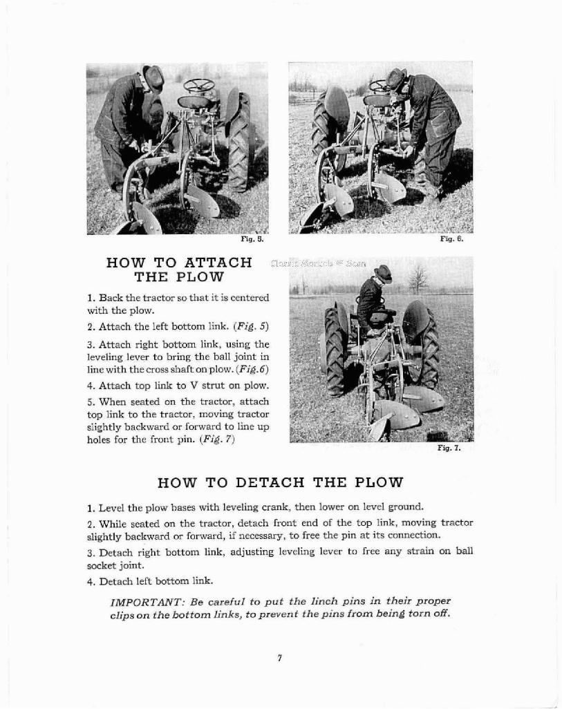
HOW T O ATTACH THE PLOW
1. Back the tractor so that it is centered with the plow.
2. Attach the left bottom link. (Fig. 5)
3. Attach right bottom link, using the leveling lever to bring the ball joint in line with the cross shaft on plow. jFig.6)
4. Attach top link to V strut on plow.
5. When seated en the tractor, attach top link to the tractor, moving tractor slightly backward or forward to line up holes for the front pin. (Fig. 7)
HOW TO DETACH THE PLOW
1. Level the plow bases with leveling crank, then lower on level ground.
2. While seated on the tractor, detach front end of the top link, moving tractor slightly backward or forward, if necessary, to free the pin a t its connection.
3. Detach right bottom link, adjusting leveling lever to free any strain on ball socket joint.
4. Detach left bottom link.
IMPORTANT: Be careful to p u t the l inch pins in their proper clips on the bot tom links, to prevent the pins from being torn off.
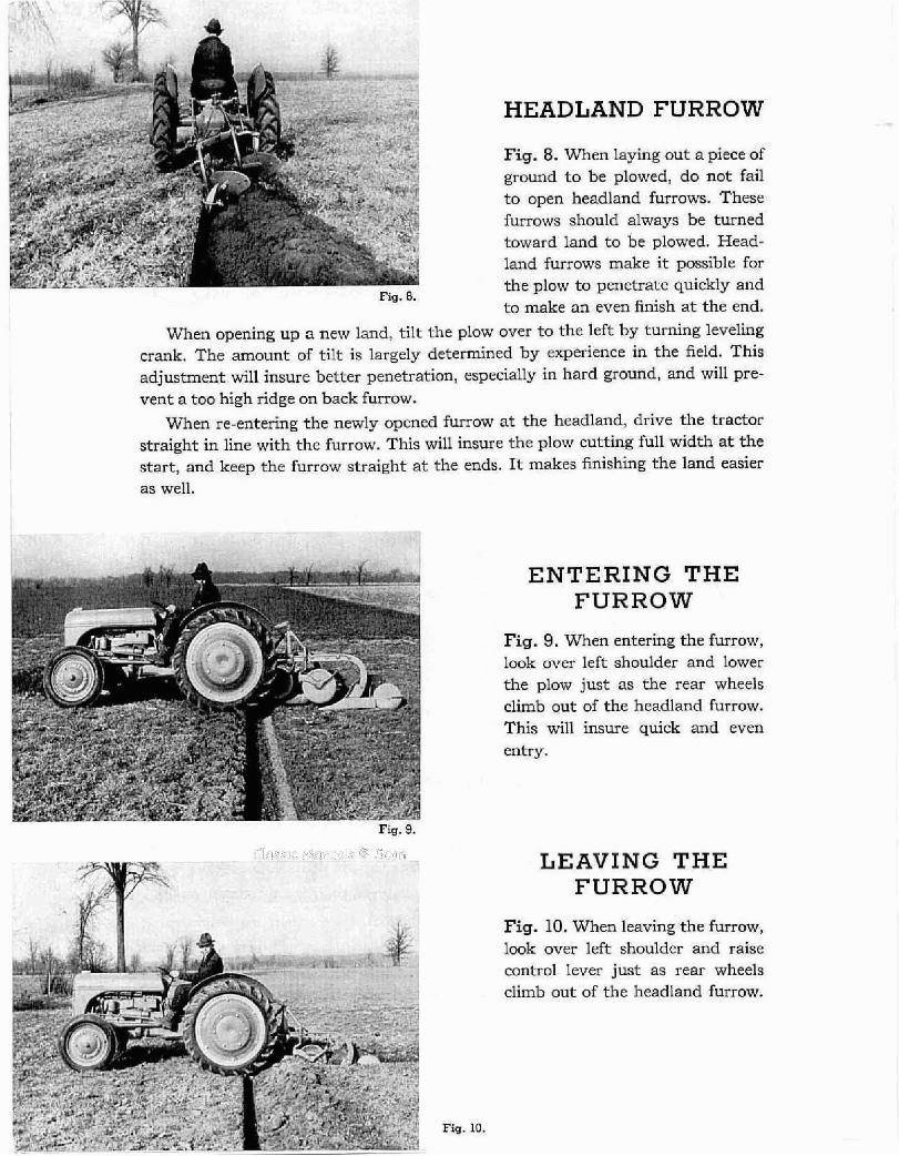
Fig. 8.
HEADLAND FURROW
Fig. 8. When laying out a piece of ground to be plowed, do not fail to open headland furrows. These furrows should always be turned toward land to be plowed. Head- land furrows make it possible for the plow to penetrate quickly and to make an even finish at the end.
When opening up a new land, tilt the plow over to the left by turning leveling crank. The amount of tilt is largely determined by experience in the field. This adjustment will insure better penetration, especially in hard ground, and will pre- vent a too high ridge on back furrow.
When re-entering the newly opened furrow a t the headland, drive the tractor straight in line with the furrow. This will insure the plow cutting full width a t the start, and keep the furrow straight a t the ends. It makes finishing the land easier as well.
ENTERING THE FURROW
Fig. 9. When entering the fwrow, look over left shoulder and lower the plow just as the rear wheels climb out of the headland furrow. This will insure quick and even entry.
LEAVING THE FURROW
Fig. 10. When leaving the furrow, look over left shoulder and raise control lever just as rear wheels climb out of the headland furrow.
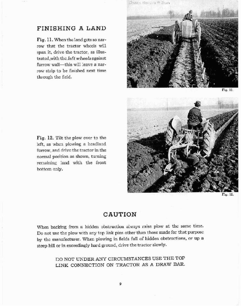
FINISHING A LAND
Fig. 11. TVhm the land gcts so nar- row that the tractor wheels ui:l span it, drive the tractor, as illus- tratcd,with thc lef t wheels against furrow wall-this will leave a nar- row strip t o be finished next time through the field.
Fig. 12. Tilt the plow over t o the left, as when plowing a headland furrow, and drive the tractor in the normal position 3s shown, turning remaining land with t h e fmt hottom only.
CAUTION
When backing from a hidden obstruftior~ always raise plow at the same bme.
Do not use the plnw wrth any top link pins other than those made for that purpose
by thc manufacturer. When plowing in fields Full of hidden obstructions, or up a steep hill or in exceedingly hard ground, drive the tractor slowly.
DO NOT UNDER ANY CIRCLXvISTANCES USE THE TOP LINK CONNECTION ON TRACTOR AS A DRAW BAR.
SUGGESTIONS IN LAYING OUT FIELDS TO BE PLOWED
The ease of operation and simplicity of the Ferguson plow readily adapts itself to any type of field to be plowed. The following suggestions as outlined are given in the hope that they will be of assistance to the plowman in doing a better plowing job, easier and quicker.
The actual work of laying out a field to be plowed should be done a t idle times. This will allow plenty of time to step off or measure the field, open headlands and back furrows. Use plenty of field markers, such as stakes. It saves lots of time, gives the operator a perfect guide for straight furrows which materially adds to the neat- ness and quality of the job.
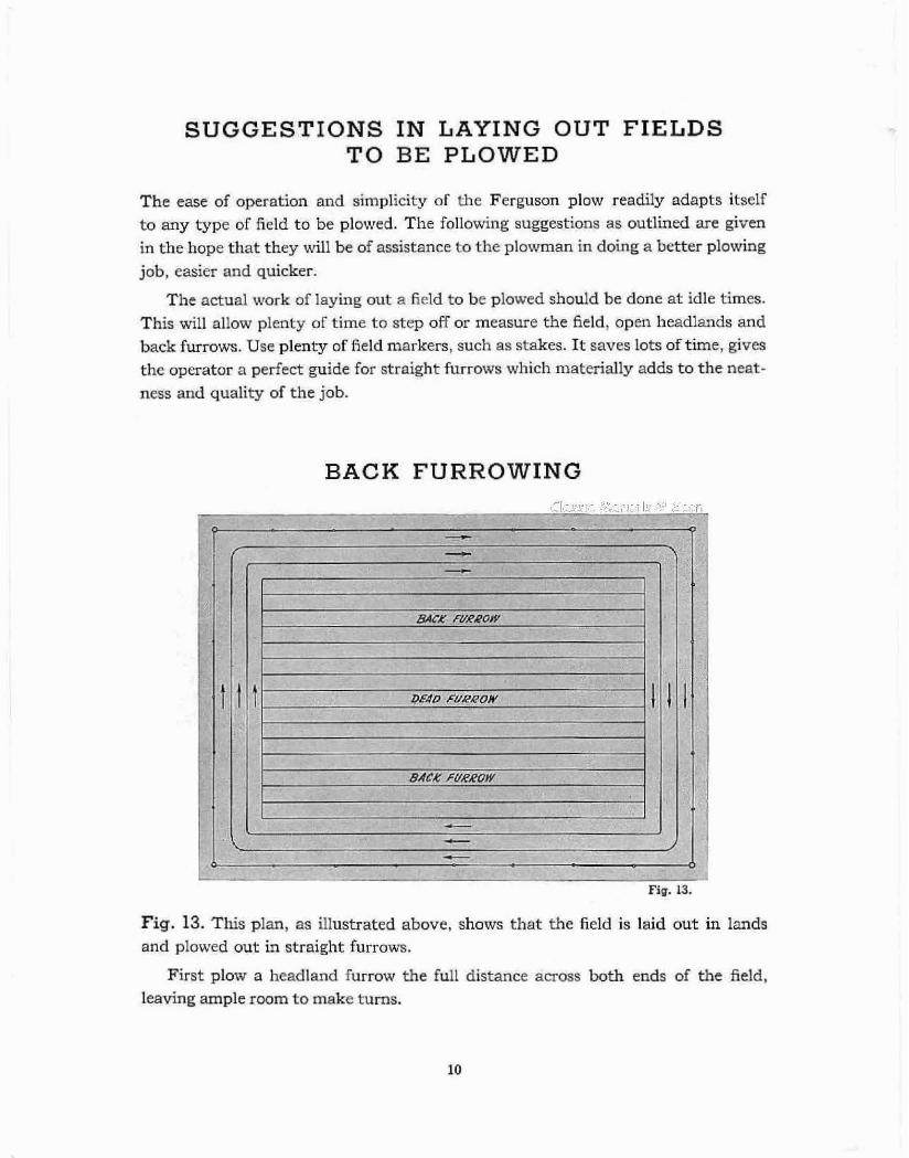
BACK FURROWING
FURROW
FURROW
Fig. 13. This plan, as illustrated above, shows that the field is laid out in lands and plowed out in straight furrows.
First plow a headland furrow the full distance across both ends of the field, leaving ample room t o make turns.

. . . . . . . .
Fig. 14.
Fig. 14. Finishing aland in an irregularly shaped field, when the plot begins to nar- row, lift the plow just as the left rear wheel of the tractor drops into the left furrow- then return empty to far end of the field and keep working the plot down in this manner.
This will leave a long narrow strip of land the length of the unplowed field and will permit finishing a dead furrow in the usual manner.
PLOWING THE FIELD TURNING SQUARE CORNERS Fig. 15. This plan is quite often used where a dead furrow in the center of thefield
is not desirable. Start with a . ~ .~ .~ I . I . -.; - Y'.. . . . < ' + ,
short back furrow in exact o center of the field. Afterback
furrowing a few rounds then startplowing furrows across the ends, making a complete turn a t the corners by loop- ing to the left.
In this way, the plowed land gradually grows larger and the dead furrows are left a t the extreme outside of the field.

WARRANTY 0
The Ferguson-Sherman Mfg. Corp. warrants the parts of all Ferguson-Sherman Mfg. Corp. implements bearing the "Ferguson" trade mark name to be free from defects in material or workmanship for a period of 90 days from date of original delivery to the owner.
This warranty shall he limited to shipment to the pur- chaser without charge except for transportation of the part or parts intended to replace those acknowledged by Ferguson-Sherman Mfg. Corp. to be defective.
If the purchaser shall use or allow to be used, on the
implements, parts not made or supplied by the Ferguson- Sherman Mfg. Corp., then this warranty shall become void immediately. The Ferguson-Sherman Mfg. Corp. does not undertake responsibilify to any purchaser of its products for any undertaking, representation or warranty made by anyone selling its products beyond those herein
The Fergusan-Sherman Mfg. Corp. reserves the right to make any changes in design and changes or improve- ments upon its implements without imposing any obli- gation to install the same upon its products heretofore manufactured.