ford1 firmware specific guide - microsoft · ford1 firmware specific guide this product is intended...
TRANSCRIPT
Directed Digital System
FORD1Firmware Specific Guide
This product is intended for installation by a professional installer only! Attempts to install this product by a person other than a trained professional may result in severe damage to a vehicle’s electrical system and components.
© 2014 Directed, Vista, CA Directed Digital System 2014-08

ContentsWarning! Safety first ....................................................................................................................... 3Introduction .................................................................................................................................... 4
Vehicle application guide ........................................................................................................... 4Understanding the Difference Between an 80 and a 40-Bit Ford ........................................................... 6
What does it mean? ................................................................................................................. 6How do I Differentiate Between the 40 and 80 Bit? ....................................................................... 6
Wiring connections ......................................................................................................................... 7Main power harness (H1), 12-pin thick gauge connector ............................................................... 7Auxiliary output harness (H2), 16-pin black connector .................................................................. 7Analog harness (H3), 18-pin white connector .............................................................................. 8MC501 harness (H4), 8 thick-gauge wires (optional) ..................................................................... 8
Installation ...................................................................................................................................... 9Wiring Diagram ........................................................................................................................ 9
Accesssory 3 relay connections ...................................................................................................... 10Vehicle wiring reference charts ....................................................................................................... 10
P.AT.S. connector ..................................................................................................................... 10Ignition Switch ........................................................................................................................ 12
Connecting the module .................................................................................................................. 29Important! .............................................................................................................................. 30Manual or automatic transmission selection ................................................................................ 30RF kits .................................................................................................................................... 31When used in conjunction with SmartStart .................................................................................. 31
Module programming ................................................................................................................... 322-key programming without Key2GO ........................................................................................ 321-Key programming using Key2GO........................................................................................... 33LED diagnostics and troubleshooting .......................................................................................... 34Module reset .......................................................................................................................... 35Hard reset .............................................................................................................................. 35
Learning the Tach (not needed with Virtual Tach) ............................................................................... 36Initializing Virtual Tach (not needed with hardwired or data tach applications) ..................................... 36Limited lifetime consumer warranty .................................................................................................. 37Quick Reference Guide – Viper, Clifford, Python, Avital & Automate.................................................... 38Quick Reference Guide – Autostart .................................................................................................. 40

3 Directed Digital System FORD1© 2014 Directed. All rights reserved.
Warning! Safety firstThe following safety warnings must be observed at all times:
• Due to the complexity of this system, installation of this product must only be performed by an authorized Directed dealer.
• When properly installed, this system can start the vehicle via a command signal from the remote control. Therefore, never operate the system in an area that does not have adequate ventilation.
The following precautions are the sole responsibility of the user; however, authorized Directed dealers should:• Never use a test light or logic probe when installing this unit. Always use a multimeter. • Never operate the system in an enclosed or partially enclosed area without ventilation (such as a garage). • When parking in an enclosed or partially enclosed area or when having the vehicle serviced, the
remote start system must be disabled using the installed toggle switch. It is the user’s sole responsibility to properly handle and keep out of reach from children all remote controls to assure that the system does not unintentionally remote start the vehicle.
• USER MUST INSTALL A CARBON MONOXIDE DETECTOR IN OR ABOUT THE LIVING AREA ADJACENT TO THE VEHICLE. ALL DOORS LEADING FROM ADJACENT LIVING AREAS TO THE ENCLOSED OR PARTIALLY ENCLOSED VEHICLE STORAGE AREA MUST REMAIN CLOSED AT ALL TIMES.
Use of this product in a manner contrary to its intended mode of operation may result in property damage, personal injury, or death. Except when performing the Safety Check outlined in this installation guide, (1) Never remotely start the vehicle with the vehicle in gear, and (2) Never remotely start the vehicle with the keys in the ignition. The user is responsible for having the neutral safety feature of the vehicle periodically checked, wherein the vehicle must not remotely start while the car is in gear. This testing should be performed by an authorized Directed dealer in accordance with the Safety Check outlined in this product installation guide. If the vehicle starts in gear, cease remote start operation immediately and consult with the user to fix the problem immediately.
OPERATION OF THE REMOTE START MODULE IF THE VEHICLE STARTS IN GEAR IS CONTRARY TO ITS INTENDED MODE OF OPERATION. OPERATING THE REMOTE START SYSTEM UNDER THESE CONDITIONS MAY RESULT IN PROPERTY DAMAGE OR PERSONAL INJURY. IMMEDIATELY CEASE THE USE OF THE UNIT AND REPAIR OR DISCONNECT THE INSTALLED REMOTE START MODULE. DIRECTED WILL NOT BE HELD RESPONSIBLE OR PAY FOR INSTALLATION OR REINSTALLATION COSTS.
Remote starters for manual transmission pose significant risks if not properly installed and operated. When testing to ensure the installation is working properly, only remote start the vehicle in neutral gear, on a flat surface and with a functional, fully engaged parking brake. Do not allow anyone to stand in front of or behind the vehicle.
This product should not be installed in any convertible vehicles, soft or hard top with a manual transmission. Installation in such vehicles may pose certain risk.

4 Directed Digital System FORD1© 2014 Directed. All rights reserved.
IntroductionThe FORD1 firmware for Directed Digital Systems is a complete solution for remote start, security (if applicable), bypass interface, and convenience needs compatible with specific Ford, Lincoln and Mercury vehicles.
Warning! This module can only be programmed via the web tool, which can be found on www.xpresskit.com or using the Directechs Mobile application for smartphones. Features and functions will become accessible when you connect the module using the XKLoader.
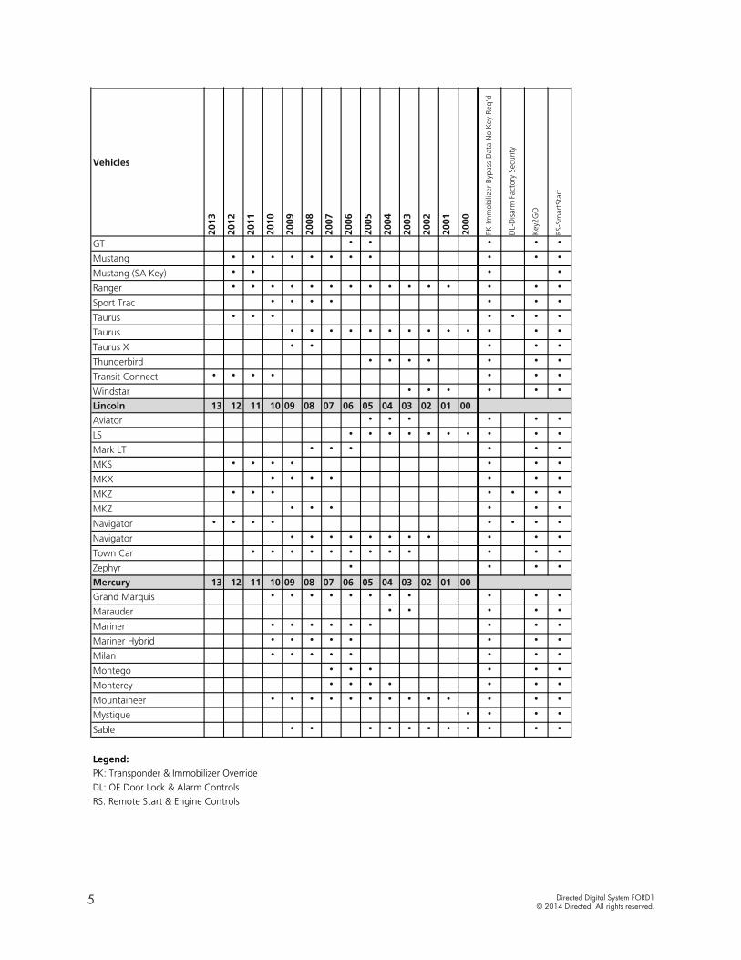
Vehicle application guideThe table below lists the vehicles and features which are compatible with this product. Refer to the following pages for more information on installation wiring, programming and troubleshooting for these vehicles. .
Vehicles
2013
2012
2011
2010
2009
2008
2007
2006
2005
2004
2003
2002
2001
2000
PK-Im
mob
ilize
r By
pass
-Dat
a N
o K
ey R
eq'd
DL-
Dis
arm
Fac
tory
Sec
urity
Key
2GO
RS-S
mar
tSta
rt
Ford
Crown Victoria • • • • • • • • • • • •
Edge • • • • • • • •
Escape • • • • • • • • • • • • •
Escape Hybrid • • • • • • • • •
E-Series • • • • • • • • •
Expedition • • • • • • • • • • • •
Explorer • • • • • • • • • • • • • •
Explorer Sport Trac • • • • • • • •
F150 • • • • •
F150 • • • • • • • • • •
F250 • • • • •
F250 • • • • • •
F350 • • • • •
F350 • • • • • •
F450 • • • • •
F450 • • • • • •
Fiesta • • • • • •
Five Hundred • • • • • •
Flex • • • • •
Focus • • • • • • • • • • • • • •
Focus • • • • •
Freestar • • • • • • •
Freestyle • • • • • •
Fusion • • • • • • •
Fusion • • • • • • •
Fusion • • • • •
Vehicles
2013
2012
2011
2010
2009
2008
2007
2006
2005
2004
2003
2002
2001
2000
PK-Im
mob
ilize
r By
pass
-Dat
a N
o K
ey R
eq'd
DL-
Dis
arm
Fac
tory
Sec
urity
Key
2GO
RS-S
mar
tSta
rt
GT • • • • •
Mustang • • • • • • • • • • •
Mustang (SA Key) • • • •
Ranger • • • • • • • • • • • • • • •
Sport Trac • • • • • • •
Taurus • • • • • • •
Taurus • • • • • • • • • • • • •
Taurus X • • • • •
Thunderbird • • • • • • •
Transit Connect • • • • • • •
Windstar • • • • • •
Lincoln 13 12 11 10 09 08 07 06 05 04 03 02 01 00
Aviator • • • • • •
LS • • • • • • • • • •
Mark LT • • • • • •
MKS • • • • • • •
MKX • • • • • • •
MKZ • • • • • • •
MKZ • • • • • •
Navigator • • • • • • • •
Navigator • • • • • • • • • • •
Town Car • • • • • • • • • • • •
Zephyr • • • •
Mercury 13 12 11 10 09 08 07 06 05 04 03 02 01 00
Grand Marquis • • • • • • • • • • •
Marauder • • • • •
Mariner • • • • • • • • •
Mariner Hybrid • • • • • • • •
Milan • • • • • • • •
Montego • • • • • •
Monterey • • • • • • •
Mountaineer • • • • • • • • • • • • •
Mystique • • • •
Sable • • • • • • • • • • •
Legend:PK: Transponder & Immobilizer Override
DL: OE Door Lock & Alarm Controls
RS: Remote Start & Engine Controls
5 Directed Digital System FORD1© 2014 Directed. All rights reserved.
Vehicles
2013
2012
2011
2010
2009
2008
2007
2006
2005
2004
2003
2002
2001
2000
PK-Im
mob
ilize
r By
pass
-Dat
a N
o K
ey R
eq'd
DL-
Dis
arm
Fac
tory
Sec
urity
Key
2GO
RS-S
mar
tSta
rt
Ford
Crown Victoria • • • • • • • • • • • •
Edge • • • • • • • •
Escape • • • • • • • • • • • • •
Escape Hybrid • • • • • • • • •
E-Series • • • • • • • • •
Expedition • • • • • • • • • • • •
Explorer • • • • • • • • • • • • • •
Explorer Sport Trac • • • • • • • •
F150 • • • • •
F150 • • • • • • • • • •
F250 • • • • •
F250 • • • • • •
F350 • • • • •
F350 • • • • • •
F450 • • • • •
F450 • • • • • •
Fiesta • • • • • •
Five Hundred • • • • • •
Flex • • • • •
Focus • • • • • • • • • • • • • •
Focus • • • • •
Freestar • • • • • • •
Freestyle • • • • • •
Fusion • • • • • • •
Fusion • • • • • • •
Fusion • • • • •
Vehicles
2013
2012
2011
2010
2009
2008
2007
2006
2005
2004
2003
2002
2001
2000
PK-Im
mob
ilize
r By
pass
-Dat
a N
o K
ey R
eq'd
DL-
Dis
arm
Fac
tory
Sec
urity
Key
2GO
RS-S
mar
tSta
rt
GT • • • • •
Mustang • • • • • • • • • • •
Mustang (SA Key) • • • •
Ranger • • • • • • • • • • • • • • •
Sport Trac • • • • • • •
Taurus • • • • • • •
Taurus • • • • • • • • • • • • •
Taurus X • • • • •
Thunderbird • • • • • • •
Transit Connect • • • • • • •
Windstar • • • • • •
Lincoln 13 12 11 10 09 08 07 06 05 04 03 02 01 00
Aviator • • • • • •
LS • • • • • • • • • •
Mark LT • • • • • •
MKS • • • • • • •
MKX • • • • • • •
MKZ • • • • • • •
MKZ • • • • • •
Navigator • • • • • • • •
Navigator • • • • • • • • • • •
Town Car • • • • • • • • • • • •
Zephyr • • • •
Mercury 13 12 11 10 09 08 07 06 05 04 03 02 01 00
Grand Marquis • • • • • • • • • • •
Marauder • • • • •
Mariner • • • • • • • • •
Mariner Hybrid • • • • • • • •
Milan • • • • • • • •
Montego • • • • • •
Monterey • • • • • • •
Mountaineer • • • • • • • • • • • • •
Mystique • • • •
Sable • • • • • • • • • • •
Legend:PK: Transponder & Immobilizer Override
DL: OE Door Lock & Alarm Controls
RS: Remote Start & Engine Controls

6 Directed Digital System FORD1© 2014 Directed. All rights reserved.
Key2GOThis feature is required if only one key is available. You can program the interface without the need for
Key2Go if two keys are present.
Key2GO has been designed and developed to bypass the advanced encryption layers found in modern vehicles. It uses an array of servers to generate a duplicate of the original key, allowing the installation of a remote starter without having to give up a key.
The advantage is that this feature allows you to use one original key and the server to configure the bypass in the vehicle.
All Key2GO-compatible firmware are clearly indicated in the function list of each vehicle search result page and will also appear on the flash page. Any first-time user must re-register to gain access to Key2GO, and some additional information will be required to complete the registration process, such as your Directed account number and store name.
Key2GO is compatible with XpressVIP 4.5 or higher and requires an XKLoader.
Refer to "Module programming" on page 32 of this guide for instructions on how to program features using Key2GO.
Understanding the Difference Between an 80 and a 40-Bit FordFord introduced an 80-bit encryption in late 2009 and this caused a lot of confusion as to which models it was available on. The main question is which models use the 80 and which use the 40 bit?
Contrary to popular belief, the SA marking on the key does NOT indicate a vehicle uses 80-bit encryption. The SA marking indicates that the key is 80-bit compatible, but the vehicle itself could still be using 40-bit encryption.
What does it mean? It means that Ford did in fact release SA keys capable of 80-bit encryption, but the same transponder can also be used in vehicles with 40-bit encryption, making it backward compatible with older vehicles. Consequently, if you see an SA key it is important that you do not automatically assume it is an 80-bit type. It all depends on the vehicle, not the key.
How do I Differentiate Between the 40 and 80 Bit?To determine which encryption type you are dealing with, you must test pin 1 at the 4-pin PATS connector at the key barrel for the following conditions to determine if it is 40 or 80-bit type.
An 80-bit vehicle should provide the following values:• NO key in barrel: 0v• Key in barrel with IGN OFF: (+) 12v• Key in barrel with IGN ON: (+) 12v
An 40-bit vehicle should provide the following values:• NO key in barrel: 0v• Key in barrel with IGN OFF: 0vKey in barrel with IGN ON: (+) 12v Note: If the key is an 80-bit type, please use FORD6 firmware.

7 Directed Digital System FORD1© 2014 Directed. All rights reserved.
Wiring connectionsYour module may come with one of two versions of wiring harnesses. It is clearly indicated in the following
tables which harnesses and wire colors can be different in your installation.
The wiring connections listed below are generic to this firwmare.
Main power harness (H1), 12-pin thick gauge connectorConn./Pin Color Description
H1/1 White Relay 3 COM – Parking Light Output 1
H1/2 White/Brown Relay 3 N.O.– Parking Light Input 1
H1/3 Brown/Red Relay 2 N.O.– No Connection
H1/4 Yellow/Red Relay 2 COM –RAP Off
H1/5 Orange/Red Relay 2 N.C. –RAP Off
H1/6 Yellow Relay 1 COM – No Connection 1
H1/7 White Relay 3 COM – Parking Light Output 1
H1/8 White/Brown Relay 3 N.O.– Parking Light Input 1
H1/9 Black (-) Ground
H1/10 Red (+) 12 Volt (Battery)
H1/11 Orange/Yellow Relay 1 N.C. – No Connection 1
H1/12 Brown Relay 1 N.O.– No Connection 1
Auxiliary output harness (H2), 16-pin black connector Your module may come with one of two versions of wiring harnesses. The column in red is for old wire
colors, and the rows with italicized text indicate where differences may occur.
Conn./Pin Color (CURRENT Harness) Color (OLD Harness) Description
H2/1 Violet/Brown Violet/Brown No Connection
H2/2 Yellow/Black Yellow/Black Data TX
H2/3 Orange/Black Orange/Black Data RX
H2/4 Tan Tan HS CAN Low
H2/5 Tan/Black Tan/Black HS CAN High
H2/6 Light Green Light Green No Connection
H2/7 Orange/Green Orange/Green No Connection
H2/8 Orange/Brown Orange/Brown No Connection
H2/9 Violet/Green Violet/Green No Connection
H2/10 Green/Black Lt. Green/White No Connection
H2/11 White/Violet White/Violet No Connection 2
H2/12 White/Red White/Red No Connection
H2/13 Lt. Blue/Black Lt. Green/Black No Connection
H2/14 Green/Red Green/Red No Connection 2
H2/15 N/A Violet/Red No Connection
H2/16 Violet/Yellow Violet/Yellow No Connection
1. If these outputs are not used by the firmware, they can be configured by the installer when the module is flashed.2. If these outputs are not used by the firmware, they can be configured by the installer when the module is flashed. Note that they are
low current and a relay may be necessary.
8 Directed Digital System FORD1© 2014 Directed. All rights reserved.
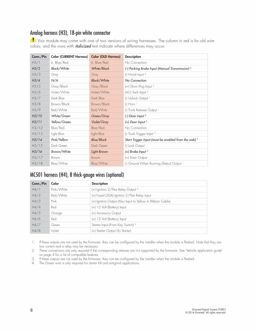
Analog harness (H3), 18-pin white connector Your module may come with one of two versions of wiring harnesses. The column in red is for old wire
colors, and the rows with italicized text indicate where differences may occur.
Conn./Pin Color (CURRENT Harness) Color (OLD Harness) Description
H3/1 Lt. Blue/Red Lt. Blue/Red No Connection
H3/2 Black/White White/Black (-) Parking Brake Input (Manual Transmission) 2
H3/3 Gray Gray (-) Hood Input 2
H3/4 N/A Black/White No Connection
H3/5 Gray/Black Gray/Black (+) Glow Plug Input 2
H3/6 Violet/White Violet/White (AC) Tach Input 2
H3/7 Dark Blue Dark Blue (-) Unlock Output 1
H3/8 Brown/Black Brown/Black (-) Horn 1
H3/9 Red/White Red/White (-) Trunk Release Output 1
H3/10 White/Green Green/Gray (-) Door Input 2
H3/11 Yellow/Green Violet/Gray (+) Door Input 2
H3/12 Blue/Red Blue/Red No Connection
H3/13 Light Blue Light Blue (-) Trunk Trigger Input 2
H3/14 Pink/Yellow Blue/Black Start Trigger Input (must be enabled from the web) 1
H3/15 Dark Green Dark Green (-) Lock Output
H3/16 Brown/White Light Brown (+) Brake Input 2
H3/17 Brown Brown (+) Siren Output
H3/18 Blue/White Blue/White (-) Ground When Running (Status) Output 1
MC501 harness (H4), 8 thick-gauge wires (optional)Conn./Pin Color Description
H4/1 Pink/White (+) Ignition 2/Flex Relay Output 3
H4/2 Red/White (+) Fused (30A) Ignition 2/Flex Relay Input
H4/3 Pink (+) Ignition Output (Also Input to Yellow in Ribbon Cable)
H4/4 Red (+) 12 Volt (Battery) Input
H4/5 Orange (+) Accessory Output
H4/6 Red (+) 12 Volt (Battery) Input
H4/7 Green Starter Input (From Key Switch) 4
H4/8 Violet (+) Starter Output (To Starter)
1. If these outputs are not used by the firmware, they can be configured by the installer when the module is flashed. Note that they are low current and a relay may be necessary.
2. These connections are only required if the corresponding statuses are not supported by the firmware. See "Vehicle application guide" on page 4 for a list of compatible features.
3. If these outputs are not used by the firmware, they can be configured by the installer when the module is flashed. 4. The Green wire is only required for starter kill and antigrind applications.
9 Directed Digital System FORD1© 2014 Directed. All rights reserved.
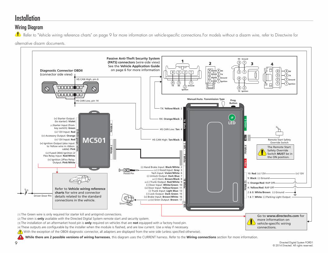
InstallationWiring Diagram
Refer to "Vehicle wiring reference charts" on page 9 for more information on vehicle-specific connections.For models without a disarm wire, refer to Directwire for
alternative disarm documents.
16
8
9
1
16 Black
3 Wh
4 Wh
ite12 W
hite
4 Red
7 Wh
ite2 W
h
2 Bk
6 Green
18 Wh
ite
Manual/Auto. Transmission Type Prog.Button
Manual/Auto. Transmission Type Prog.Button
Diagnostic Connector OBDII(connector side view)
Passive Anti-Theft Security System(PATS) connectors (wire-side view)See the Vehicle Application Guide
on page 6 for more information
HS CAN Low, pin 14
Driver Door Pin
HS CAN High, pin 6
HS CAN High: Tan/Black: 5
HS CAN Low: Tan: 4
TX: Yellow/Black: 2
RX: Orange/Black: 3
9: Black: (-) Ground
4: Yellow/Red: RAP Off
5: Orange/Red: RAP Off
2 & 8: White/Brown: (-) Ground
1 & 7: White: (-) Parking Light Output
10: Red: (+) 12V (+) 12V
[4] These outputs are configurable by the installer when the module is flashed, and are low current. Use a relay if necessary.
Ignition
RXTX Ground
1
4 3
2
1
4 3 2 1
2
Ignition
RX
TX
Ground
4
123
4
123
3Ground
TX
RX
Ignition
3 1
3
2
1
4
24
4
RX4
TX3
Ground2
Ignition1
4
3
2
1
Refer to Vehicle wiring reference charts for wire and connector details related to the standard connections in the vehicle.
[3] (-) Hood Input: Gray: 3(-) Hand Brake Input: Black/White: 2
Tach Input: Violet/White: 6(-) Unlock Output: Dark Blue: 7
(-) Lock Output: Dark Green: 15
[4] (-) Trunk Output: Red/White: 9
(-) Trunk Input: Light Blue: 13
(-) Door Input: White/Green: 10(+) Door Input: Yellow/Green: 11
(+) Brake Input: Brown/White: 16
[4] (-) Horn: Brown/Black: 8
7 Wh
ite4 W
hite
8 thick-g
aug
e wires
MC501
(+) Ignition 2/Flex Relay Output: Pink/White
(+) Ignition Output (also input to Yellow wire in ribbon
cable): Pink
(+) 12V Input: Red
(+) Accessory Output: Orange
(+) 12V Input: Red
[1] Starter Input (from key switch): Green
(+) Starter Output (to starter): Violet
(+) Fused (30A) Ignition 2/Flex Relay Input: Red/White
The Remote Start Safety Override Switch MUST be in the ON position.
Remote Start SafetyOverride Switch
[1] The Green wire is only required for starter kill and antigrind connections.
[3] The installation of an aftermarket hood pin is only required on vehicles that are not equipped with a factory hood pin.
With the exception of the OBDII diagnostic connector, all adapters are displayed from the wire side (unless specified otherwise).
[2] The siren is only available with the Directed Digital System remote start and security system.Go to www.directechs.com for more information on vehicle-specific wiring connections.
[2] (+) Siren Output: Brown: 17
Siren
Hood Pin
While there are 2 possible versions of wiring harnesses, this diagram uses the CURRENT harness. Refer to the Wiring connections section for more information.

10 Directed Digital System FORD1© 2014 Directed. All rights reserved.
Accesssory 3 relay connectionsIf the vehicle on which you are performing an installation requires the Accessory 3 wire, you must install a relay.
86(+) Accessory 1
(from remote starter)
(+) 12v
(+) Accessory 3 (in vehicle)
(-) Active While Running (status)8530
87a
87
Vehicle wiring reference chartsThis section provides information on the following connections: • "P.AT.S. connector" • "Ignition Switch"
Refer to www.directechs.com for more information on any additional connections.
P.AT.S. connector
Ignition
RXTX Ground
1
4 3
2
1
4 3 2 1
2
Ignition
RX
TX
Ground
4
123
4
123
3Ground
TX
RX
Ignition
3 1
3
2
1
4
24
4
RX4
TX3
Ground2
Ignition1
4
3
2
1
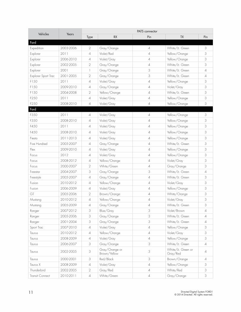
Vehicles YearsPATS connector
Type RX Pin TX Pin
Ford
Crown Victoria 2005-2011 4 Gray/Orange 4 White/Lt. Green 3
Crown Victoria 2003-2004 4 Gray/Orange 3 White/Lt. Green 4
Econoline 2009-2012 3 Violet/Gray 3 Yellow/Orange 4
Econoline 2008 3 Gray/Orange 3 White/Lt.Green 4
Edge 2011-2013 4 Violet/Gray 4 Yellow/Orange 3
Edge 2007-2010 4 Yellow/Orange 4 Violet/Gray 3
Escape 2008-2012 4 Violet/Gray 4 Yellow/Orange 3
Escape 2001-2007 2 Red/Black 4 Brown/Orange 3
Escape Hybrid 2008-2012 4 Violet/Gray 4 Yellow/Orange 3
Escape Hybrid 2005-2007 2 Red/Black 4 Brown/Orange 3
E-Series 2009-2012 3 Violet/Gray 3 Yellow/Orange 4
E-Series 2008 3 Gray/Orange 3 White/Lt. Green 4
Excursion 2004-2005 3 Gray/Orange 3 White/Lt. Green 4
Excursion 2002-2003 1 Gray/Orange 3 White/Lt. Green 4
Expedition 2007-2011 4 Blue/Gray 4 Violet/Brown 3
11 Directed Digital System FORD1© 2014 Directed. All rights reserved.
Vehicles YearsPATS connector
Type RX Pin TX Pin
Ford
Expedition 2003-2006 2 Gray/Orange 4 White/Lt. Green 3
Explorer 2011 4 Violet/Red 4 Yellow/Orange 3
Explorer 2006-2010 4 Violet/Gray 4 Yellow/Orange 3
Explorer 2002-2005 2 Gray/Orange 4 White/Lt. Green 3
Explorer 2001 1 Gray/Orange 3 White/Lt. Green 4
Explorer Sport Trac 2001-2005 2 Gray/Orange 3 White/Lt. Green 4
F150 2011 4 Violet/Gray 4 Yellow/Orange 3
F150 2009-2010 4 Gray/Orange 4 Violet/Gray 3
F150 2004-2008 2 Yellow/Orange 4 White/Lt. Green 3
F250 2011 4 Violet/Gray 4 Yellow/Orange 3
F250 2008-2010 4 Violet/Gray 4 Yellow/Orange 3
Ford
F350 2011 4 Violet/Gray 4 Yellow/Orange 3
F350 2008-2010 4 Violet/Gray 4 Yellow/Orange 3
F450 2011 4 Violet/Gray 4 Yellow/Orange 3
F450 2008-2010 4 Violet/Gray 4 Yellow/Orange 3
Fiesta 2011-2013 4 Violet/Gray 4 Yellow/Orange 3
Five Hundred 2005-2007 4 Gray/Orange 4 White/Lt. Green 3
Flex 2009-2010 4 Violet/Gray 4 Yellow/Orange 3
Focus 2012 4 Violet/Gray 4 Yellow/Orange 3
Focus 2008-2012 4 Yellow/Orange 4 Violet/Gray 3
Focus 2000-2007 2 White/Green 4 Gray/Orange 3
Freestar 2004-2007 3 Gray/Orange 3 White/Lt. Green 4
Freestyle 2005-2007 4 Gray/Orange 4 White/Lt. Green 3
Fusion 2010-2012 4 Yellow/Orange 4 Violet/Gray 3
Fusion 2006-2009 4 Violet/Gray 4 Yellow/Orange 3
GT 2005-2006 2 Brown/Orange 4 White/Orange 3
Mustang 2010-2012 4 Yellow/Orange 4 Violet/Gray 3
Mustang 2005-2009 4 Gray/Orange 4 White/Lt. Green 3
Ranger 2007-2012 3 Blue/Gray 3 Violet/Brown 4
Ranger 2005-2006 3 Gray/Orange 3 White/Lt. Green 4
Ranger 2001-2004 3 Gray/Orange 3 White/Lt. Green 4
Sport Trac 2007-2010 4 Violet/Gray 4 Yellow/Orange 3
Taurus 2010-2012 4 Yellow/Orange 4 Violet/Gray 3
Taurus 2008-2009 4 Violet/Gray 4 Yellow/Orange 3
Taurus 2006-2007 3 Gray/Orange 3 White/Lt. Green 4
Taurus 2002-2005 3 Gray/Orange or Brown/Yellow 3 White/Lt. Green or
Gray/Red 4
Taurus 2000-2001 3 Red/Black 3 Brown/Orange 4
Taurus X 2008-2009 4 Violet/Gray 4 Yellow/Orange 3
Thunderbird 2002-2005 2 Gray/Red 4 White/Red 3
Transit Connect 2010-2011 4 White/Green 4 Gray/Orange 3

12 Directed Digital System FORD1© 2014 Directed. All rights reserved.
Vehicles YearsPATS connector
Type RX Pin TX Pin
Ford
Windstar 2002-2003 3 Gray/Orange 3 White/Lt. Green 4
Windstar 2001 1 Gray/Orange 3 White/Lt. Green 4
Lincoln
Aviator 2003-2005 2 Gray/Orange 4 White/Lt. Green 3
LS 2000-2006 2 Gray/Red 4 White/Red 3
Mark LT 2006-2008 2 Gray/Orange 4 White/Lt. Green 3
MKS 2009-2012 4 Yellow/Orange 4 Violet/Gray 3
MKX 2007-2010 4 Yellow/Orange 4 Violet/Gray 3
MKZ 2010-2012 4 Yellow/Orange 4 Violet/Gray 3
MKZ 2007-2009 4 Violet/Gray 4 Yellow/Orange 3
Navigator 2007-2012 4 Blue/Gray 4 Violet/Brown 3
Navigator 2003-2006 2 Gray/Orange 4 White/Lt. Green 3
Navigator 2002 1 Gray/Orange 4 White/Lt. Green 3
Vehicles YearsPATS connector
Type RX Pin TX Pin
Lincoln
Town Car 2005-2011 4 Gray/Orange 4 White/Lt. Green 3
Town Car 2003-2004 3 Gray/Orange 3 White/Lt. Green 4
Zephyr 2006 4 Yellow/Orange 4 Violet/Gray 3
Mercury
Grand Marquis 2005-2010 4 Gray/Orange 4 White/Lt. Green 3
Grand Marquis 2003-2004 3 Gray/Orange 3 White/Lt. Green 4
Marauder 2003-2004 3 Gray/Orange 3 White/Lt. Green 4
Mariner 2008-2010 4 Violet/Gray 4 Yellow/Orange 3
Mariner 2005-2007 2 Red/Black 4 Brown/Orange 3
Mariner Hybrid 2008-2010 4 Violet/Gray 4 Yellow/Orange 3
Mariner Hybrid 2006-2007 2 Red/Black 4 Brown/Orange 3
Milan 2010 4 Yellow/Orange 4 Violet/Gray 3
Milan 2006-2009 4 Violet/Gray 4 Yellow/Orange 3
Montego 2005-2007 4 Gray/Orange 4 White/Lt. Green 3
Monterey 2004-2007 3 Gray/Orange 3 White/Lt. Green 4
Mountaineer 2006-2010 4 Violet/Gray 4 Yellow/Orange 3
Mountaineer 2002-2005 2 Gray/Orange 4 White/Lt. Green 3
Mountaineer 2001 1 Gray/Orange 3 White/Lt. Green 4
Mystique 2000 2 White/Green 4 Gray/Orange 3
Sable 2008-2009 1 Violet/Gray 4 Yellow/Orange 3
Sable 2002-2005 1 Gray/Orange or Brown/Yellow 3 White/Lt. Green or
Gray/Red 4
Sable 2000-2001 1 Red/Black 3 Brown/Orange 4

13 Directed Digital System FORD1© 2014 Directed. All rights reserved.
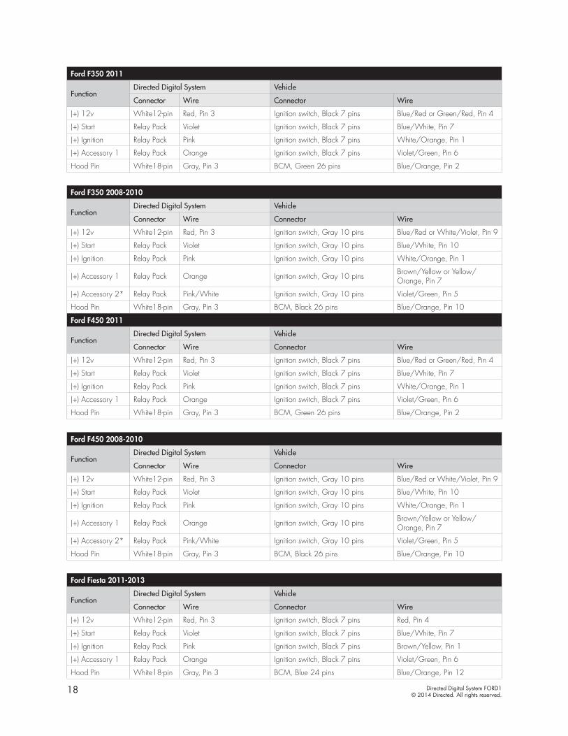
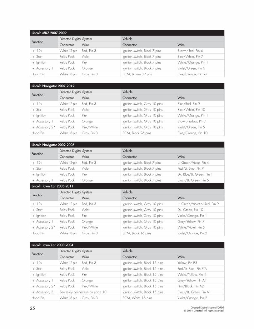
Ignition Switch* This wire must be programmed for accessory.Ford Crown Victoria 2005-2011
FunctionDirected Digital System Vehicle
Connector Wire Connector Wire
(+) 12v White12-pin Red, Pin 3 Ignition switch, Gray 10 pins Lt. Green/Violet, Pin 9
(+) Start Relay Pack Violet Ignition switch, Gray 10 pins Dark Green, Pin 10
(+) Ignition Relay Pack Pink Ignition switch, Gray 10 pins Violet/Orange, Pin 1
(+) Accessory 1 Relay Pack Orange Ignition switch, Gray 10 pins Gray/Yellow, Pin 7
(+) Accessory 2* Relay Pack Pink/White Ignition switch, Gray 10 pins White/Violet, Pin 5
Ford Crown Victoria 2003-2004
FunctionDirected Digital System Vehicle
Connector Wire Connector Wire
(+) 12v White12-pin Red, Pin 3 Ignition switch, Black 15 pins Lt. Green, Pin B3
(+) Start Relay Pack Violet Ignition switch, Black 15 pins Red/Lt. Blue, Pin STA
(+) Ignition Relay Pack Pink Ignition switch, Black 15 pins White/Yellow, Pin I1
(+) Accessory 1 Relay Pack Orange Ignition switch, Black 15 pins Gray/Yellow, Pin A2
(+) Accessory 2* Relay Pack Pink/White Ignition switch, Black 15 pins Pink/Black, Pin A4
(+) Accessory 3 See relay connection on page 10 Ignition switch, Black 15 pins Black/Lt. Green, Pin A1
Ford Econoline 2009-2012
FunctionDirected Digital System Vehicle
Connector Wire Connector Wire
(+) 12v White12-pin Red, Pin 3 Ignition switch, Gray 13 pins Blue/Red or Green/Red, Pin 2
(+) Start Relay Pack Violet Ignition switch, Gray 13 pins Blue/White, Pin 5
(+) Ignition Relay Pack Pink Ignition switch, Gray 13 pins White/Orange, Pin 1
(+) Accessory 1 Relay Pack Orange Ignition switch, Gray 13 pins Brown/Yellow, Pin 8
(+) Accessory 2* Relay Pack Pink/White Ignition switch, Gray 13 pins Violet/Green, Pin 3
Ford Econoline 2008
FunctionDirected Digital System Vehicle
Connector Wire Connector Wire
(+) 12v White12-pin Red, Pin 3 Ignition switch, Gray 13 pins Lt. Green/Violet, Pin 2
(+) Start Relay Pack Violet Ignition switch, Gray 13 pins White/Pink, Pin 5
(+) Ignition Relay Pack Pink Ignition switch, Gray 13 pins Pink/Lt. Green, Pin 1
(+) Accessory 1 Relay Pack Orange Ignition switch, Gray 13 pins Gray/Yellow, Pin 8
(+) Accessory 2* Relay Pack Pink/White Ignition switch, Gray 13 pins Black/Lt. Green, Pin 3
Ford Edge 2007-2010
FunctionDirected Digital System Vehicle
Connector Wire Connector Wire
(+) 12v White12-pin Red, Pin 3 Ignition switch, Black 7 pins Blue/Red, Pin 4
(+) Start Relay Pack Violet Ignition switch, Black 7 pins Blue/White, Pin 7
(+) Ignition Relay Pack Pink Ignition switch, Black 7 pins White/Orange, Pin 1
(+) Accessory 1 Relay Pack Orange Ignition switch, Black 7 pins Violet/Green, Pin 6
Hood Pin White18-pin Gray, Pin 3 BCM, Black 26 pins Blue/Orange, Pin 10

14 Directed Digital System FORD1© 2014 Directed. All rights reserved.
Ford Escape 2008-2012
FunctionDirected Digital System Vehicle
Connector Wire Connector Wire
(+) 12v White12-pin Red, Pin 3 Ignition switch, Black 7 pins Blue/Red, Pin 4
(+) Start Relay Pack Violet Ignition switch, Black 7 pins Blue/White, Pin 7
(+) Ignition Relay Pack Pink Ignition switch, Black 7 pins White/Orange, Pin 1
(+) Accessory 1 Relay Pack Orange Ignition switch, Black 7 pins Violet/Green, Pin 6
Ford Escape 2001-2007
FunctionDirected Digital System Vehicle
Connector Wire Connector Wire
(+) 12v White12-pin Red, Pin 3 Ignition switch, Black 7 pins Red, Pin 4
(+) Start Relay Pack Violet Ignition switch, Black 7 pins Tan/Lt. Blue, Pin 7
(+) Ignition Relay Pack Pink Ignition switch, Black 7 pins Lt. Green/Violet, Pin 1
(+) Accessory 1 Relay Pack Orange Ignition switch, Black 7 pins Black/Lt. Green, Pin 6
Hood Pin White18-pin Gray, Pin 3 BCM, Black 32 pins Violet/Orange, Pin 5
Ford Escape Hybrid 2008-2012
FunctionDirected Digital System Vehicle
Connector Wire Connector Wire
(+) 12v White12-pin Red, Pin 3 Ignition switch, Black 7 pins Blue/Red, Pin 4
(+) Start Relay Pack Violet Ignition switch, Black 7 pins Blue/White, Pin 7
(+) Ignition Relay Pack Pink Ignition switch, Black 7 pins White/Orange, Pin 1
(+) Accessory 1 Relay Pack Orange Ignition switch, Black 7 pins Violet/Green, Pin 6
Ford Escape Hybrid 2005-2007
FunctionDirected Digital System Vehicle
Connector Wire Connector Wire
(+) 12v White12-pin Red, Pin 3 Ignition switch, Black 7 pins Red, Pin 4
(+) Start Relay Pack Violet Ignition switch, Black 7 pins Tan/Lt. Blue, Pin 7
(+) Ignition Relay Pack Pink Ignition switch, Black 7 pins Lt. Green/Violet, Pin 1
(+) Accessory 1 Relay Pack Orange Ignition switch, Black 7 pins Black/Lt. Green, Pin 6
Hood Pin White18-pin Gray, Pin 3 BCM, Black 32 pins Violet/Orange, Pin 5
Ford E-Series 2009-2012
FunctionDirected Digital System Vehicle
Connector Wire Connector Wire
(+) 12v White12-pin Red, Pin 3 Ignition switch, Gray 13 pins Blue/Red or Green/Red, Pin 2
(+) Start Relay Pack Violet Ignition switch, Gray 13 pins Blue/White, Pin 5
(+) Ignition Relay Pack Pink Ignition switch, Gray 13 pins White/Orange, Pin 1
(+) Accessory 1 Relay Pack Orange Ignition switch, Gray 13 pins Brown/Yellow, Pin 8
(+) Accessory 2* Relay Pack Pink/White Ignition switch, Gray 13 pins Violet/Green, Pin 3
15 Directed Digital System FORD1© 2014 Directed. All rights reserved.
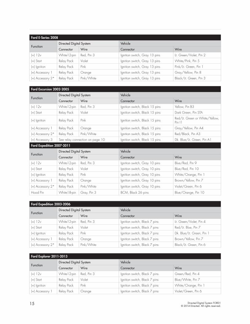
Ford E-Series 2008
FunctionDirected Digital System Vehicle
Connector Wire Connector Wire
(+) 12v White12-pin Red, Pin 3 Ignition switch, Gray 13 pins Lt. Green/Violet, Pin 2
(+) Start Relay Pack Violet Ignition switch, Gray 13 pins White/Pink, Pin 5
(+) Ignition Relay Pack Pink Ignition switch, Gray 13 pins Pink/Lt. Green, Pin 1
(+) Accessory 1 Relay Pack Orange Ignition switch, Gray 13 pins Gray/Yellow, Pin 8
(+) Accessory 2* Relay Pack Pink/White Ignition switch, Gray 13 pins Black/Lt. Green, Pin 3
Ford Excursion 2002-2005
FunctionDirected Digital System Vehicle
Connector Wire Connector Wire
(+) 12v White12-pin Red, Pin 3 Ignition switch, Black 15 pins Yellow, Pin B3
(+) Start Relay Pack Violet Ignition switch, Black 15 pins Dark Green, Pin STA
(+) Ignition Relay Pack Pink Ignition switch, Black 15 pins Red/Lt. Green or White/Yellow, Pin I1
(+) Accessory 1 Relay Pack Orange Ignition switch, Black 15 pins Gray/Yellow, Pin A4
(+) Accessory 2* Relay Pack Pink/White Ignition switch, Black 15 pins Red/Black, Pin A3
(+) Accessory 3 See relay connection on page 10 Ignition switch, Black 15 pins Dk. Blue/Lt. Green, Pin A1
Ford Expedition 2007-2011
FunctionDirected Digital System Vehicle
Connector Wire Connector Wire
(+) 12v White12-pin Red, Pin 3 Ignition switch, Gray 10 pins Blue/Red, Pin 9
(+) Start Relay Pack Violet Ignition switch, Gray 10 pins Blue/Red, Pin 10
(+) Ignition Relay Pack Pink Ignition switch, Gray 10 pins White/Orange, Pin 1
(+) Accessory 1 Relay Pack Orange Ignition switch, Gray 10 pins Brown/Yellow, Pin 7
(+) Accessory 2* Relay Pack Pink/White Ignition switch, Gray 10 pins Violet/Green, Pin 6
Hood Pin White18-pin Gray, Pin 3 BCM, Black 26 pins Blue/Orange, Pin 10
Ford Expedition 2003-2006
FunctionDirected Digital System Vehicle
Connector Wire Connector Wire
(+) 12v White12-pin Red, Pin 3 Ignition switch, Black 7 pins Lt. Green/Violet, Pin 4
(+) Start Relay Pack Violet Ignition switch, Black 7 pins Red/Lt. Blue, Pin 7
(+) Ignition Relay Pack Pink Ignition switch, Black 7 pins Dk. Blue/Lt. Green, Pin 1
(+) Accessory 1 Relay Pack Orange Ignition switch, Black 7 pins Brown/Yellow, Pin 7
(+) Accessory 2* Relay Pack Pink/White Ignition switch, Black 7 pins Black/Lt. Green, Pin 6
Ford Explorer 2011-2013
FunctionDirected Digital System Vehicle
Connector Wire Connector Wire
(+) 12v White12-pin Red, Pin 3 Ignition switch, Black 7 pins Green/Red, Pin 4
(+) Start Relay Pack Violet Ignition switch, Black 7 pins Blue/White, Pin 7
(+) Ignition Relay Pack Pink Ignition switch, Black 7 pins White/Orange, Pin 1
(+) Accessory 1 Relay Pack Orange Ignition switch, Black 7 pins Violet/Green, Pin 6
16 Directed Digital System FORD1© 2014 Directed. All rights reserved.
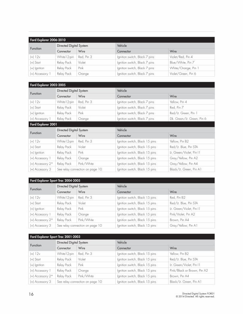
Ford Explorer 2006-2010
FunctionDirected Digital System Vehicle
Connector Wire Connector Wire
(+) 12v White12-pin Red, Pin 3 Ignition switch, Black 7 pins Violet/Red, Pin 4
(+) Start Relay Pack Violet Ignition switch, Black 7 pins Blue/White, Pin 7
(+) Ignition Relay Pack Pink Ignition switch, Black 7 pins White/Orange, Pin 1
(+) Accessory 1 Relay Pack Orange Ignition switch, Black 7 pins Violet/Green, Pin 6
Ford Explorer 2002-2005
FunctionDirected Digital System Vehicle
Connector Wire Connector Wire
(+) 12v White12-pin Red, Pin 3 Ignition switch, Black 7 pins Yellow, Pin 4
(+) Start Relay Pack Violet Ignition switch, Black 7 pins Red, Pin 7
(+) Ignition Relay Pack Pink Ignition switch, Black 7 pins Red/Lt. Green, Pin 1
(+) Accessory 1 Relay Pack Orange Ignition switch, Black 7 pins Dk. Green/Lt. Green, Pin 6
Ford Explorer 2001
FunctionDirected Digital System Vehicle
Connector Wire Connector Wire
(+) 12v White12-pin Red, Pin 3 Ignition switch, Black 15 pins Yellow, Pin B2
(+) Start Relay Pack Violet Ignition switch, Black 15 pins Red/Lt. Blue, Pin STA
(+) Ignition Relay Pack Pink Ignition switch, Black 15 pins Lt. Green/Violet, Pin I1
(+) Accessory 1 Relay Pack Orange Ignition switch, Black 15 pins Gray/Yellow, Pin A2
(+) Accessory 2* Relay Pack Pink/White Ignition switch, Black 15 pins Gray/Yellow, Pin A4
(+) Accessory 3 See relay connection on page 10 Ignition switch, Black 15 pins Black/Lt. Green, Pin A1
Ford Explorer Sport Trac 2004-2005
FunctionDirected Digital System Vehicle
Connector Wire Connector Wire
(+) 12v White12-pin Red, Pin 3 Ignition switch, Black 15 pins Red, Pin B2
(+) Start Relay Pack Violet Ignition switch, Black 15 pins Red/Lt. Blue, Pin STA
(+) Ignition Relay Pack Pink Ignition switch, Black 15 pins Lt. Green/Violet, Pin I1
(+) Accessory 1 Relay Pack Orange Ignition switch, Black 15 pins Pink/Violet, Pin A2
(+) Accessory 2* Relay Pack Pink/White Ignition switch, Black 15 pins Brown, Pin A4
(+) Accessory 3 See relay connection on page 10 Ignition switch, Black 15 pins Gray/Yellow, Pin A1
Ford Explorer Sport Trac 2001-2003
FunctionDirected Digital System Vehicle
Connector Wire Connector Wire
(+) 12v White12-pin Red, Pin 3 Ignition switch, Black 15 pins Yellow, Pin B2
(+) Start Relay Pack Violet Ignition switch, Black 15 pins Red/Lt. Blue, Pin STA
(+) Ignition Relay Pack Pink Ignition switch, Black 15 pins Lt. Green/Violet, Pin I1
(+) Accessory 1 Relay Pack Orange Ignition switch, Black 15 pins Pink/Black or Brown, Pin A2
(+) Accessory 2* Relay Pack Pink/White Ignition switch, Black 15 pins Brown, Pin A4
(+) Accessory 3 See relay connection on page 10 Ignition switch, Black 15 pins Black/Lt. Green, Pin A1
17 Directed Digital System FORD1© 2014 Directed. All rights reserved.
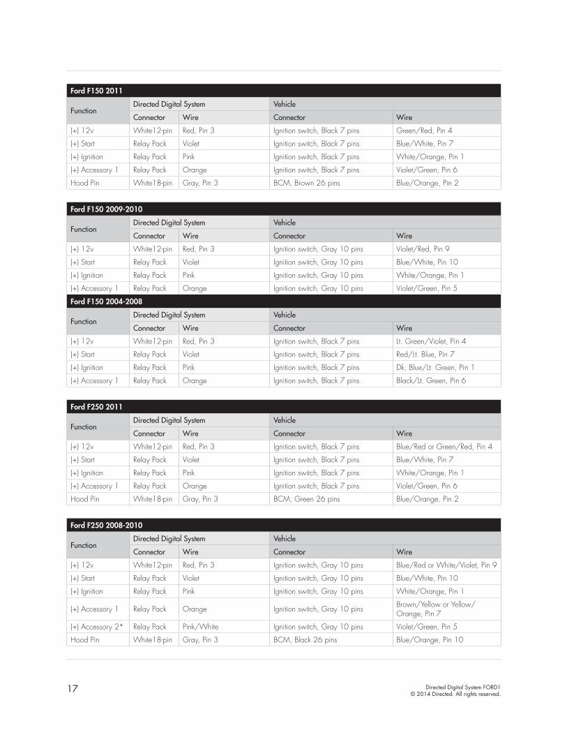
Ford F150 2011
FunctionDirected Digital System Vehicle
Connector Wire Connector Wire
(+) 12v White12-pin Red, Pin 3 Ignition switch, Black 7 pins Green/Red, Pin 4
(+) Start Relay Pack Violet Ignition switch, Black 7 pins Blue/White, Pin 7
(+) Ignition Relay Pack Pink Ignition switch, Black 7 pins White/Orange, Pin 1
(+) Accessory 1 Relay Pack Orange Ignition switch, Black 7 pins Violet/Green, Pin 6
Hood Pin White18-pin Gray, Pin 3 BCM, Brown 26 pins Blue/Orange, Pin 2
Ford F150 2009-2010
FunctionDirected Digital System Vehicle
Connector Wire Connector Wire
(+) 12v White12-pin Red, Pin 3 Ignition switch, Gray 10 pins Violet/Red, Pin 9
(+) Start Relay Pack Violet Ignition switch, Gray 10 pins Blue/White, Pin 10
(+) Ignition Relay Pack Pink Ignition switch, Gray 10 pins White/Orange, Pin 1
(+) Accessory 1 Relay Pack Orange Ignition switch, Gray 10 pins Violet/Green, Pin 5
Ford F150 2004-2008
FunctionDirected Digital System Vehicle
Connector Wire Connector Wire
(+) 12v White12-pin Red, Pin 3 Ignition switch, Black 7 pins Lt. Green/Violet, Pin 4
(+) Start Relay Pack Violet Ignition switch, Black 7 pins Red/Lt. Blue, Pin 7
(+) Ignition Relay Pack Pink Ignition switch, Black 7 pins Dk. Blue/Lt. Green, Pin 1
(+) Accessory 1 Relay Pack Orange Ignition switch, Black 7 pins Black/Lt. Green, Pin 6
Ford F250 2011
FunctionDirected Digital System Vehicle
Connector Wire Connector Wire
(+) 12v White12-pin Red, Pin 3 Ignition switch, Black 7 pins Blue/Red or Green/Red, Pin 4
(+) Start Relay Pack Violet Ignition switch, Black 7 pins Blue/White, Pin 7
(+) Ignition Relay Pack Pink Ignition switch, Black 7 pins White/Orange, Pin 1
(+) Accessory 1 Relay Pack Orange Ignition switch, Black 7 pins Violet/Green, Pin 6
Hood Pin White18-pin Gray, Pin 3 BCM, Green 26 pins Blue/Orange, Pin 2
Ford F250 2008-2010
FunctionDirected Digital System Vehicle
Connector Wire Connector Wire
(+) 12v White12-pin Red, Pin 3 Ignition switch, Gray 10 pins Blue/Red or White/Violet, Pin 9
(+) Start Relay Pack Violet Ignition switch, Gray 10 pins Blue/White, Pin 10
(+) Ignition Relay Pack Pink Ignition switch, Gray 10 pins White/Orange, Pin 1
(+) Accessory 1 Relay Pack Orange Ignition switch, Gray 10 pins Brown/Yellow or Yellow/Orange, Pin 7
(+) Accessory 2* Relay Pack Pink/White Ignition switch, Gray 10 pins Violet/Green, Pin 5
Hood Pin White18-pin Gray, Pin 3 BCM, Black 26 pins Blue/Orange, Pin 10
18 Directed Digital System FORD1© 2014 Directed. All rights reserved.
Ford F350 2011
FunctionDirected Digital System Vehicle
Connector Wire Connector Wire
(+) 12v White12-pin Red, Pin 3 Ignition switch, Black 7 pins Blue/Red or Green/Red, Pin 4
(+) Start Relay Pack Violet Ignition switch, Black 7 pins Blue/White, Pin 7
(+) Ignition Relay Pack Pink Ignition switch, Black 7 pins White/Orange, Pin 1
(+) Accessory 1 Relay Pack Orange Ignition switch, Black 7 pins Violet/Green, Pin 6
Hood Pin White18-pin Gray, Pin 3 BCM, Green 26 pins Blue/Orange, Pin 2
Ford F350 2008-2010
FunctionDirected Digital System Vehicle
Connector Wire Connector Wire
(+) 12v White12-pin Red, Pin 3 Ignition switch, Gray 10 pins Blue/Red or White/Violet, Pin 9
(+) Start Relay Pack Violet Ignition switch, Gray 10 pins Blue/White, Pin 10
(+) Ignition Relay Pack Pink Ignition switch, Gray 10 pins White/Orange, Pin 1
(+) Accessory 1 Relay Pack Orange Ignition switch, Gray 10 pins Brown/Yellow or Yellow/Orange, Pin 7
(+) Accessory 2* Relay Pack Pink/White Ignition switch, Gray 10 pins Violet/Green, Pin 5
Hood Pin White18-pin Gray, Pin 3 BCM, Black 26 pins Blue/Orange, Pin 10
Ford F450 2011
FunctionDirected Digital System Vehicle
Connector Wire Connector Wire
(+) 12v White12-pin Red, Pin 3 Ignition switch, Black 7 pins Blue/Red or Green/Red, Pin 4
(+) Start Relay Pack Violet Ignition switch, Black 7 pins Blue/White, Pin 7
(+) Ignition Relay Pack Pink Ignition switch, Black 7 pins White/Orange, Pin 1
(+) Accessory 1 Relay Pack Orange Ignition switch, Black 7 pins Violet/Green, Pin 6
Hood Pin White18-pin Gray, Pin 3 BCM, Green 26 pins Blue/Orange, Pin 2
Ford F450 2008-2010
FunctionDirected Digital System Vehicle
Connector Wire Connector Wire
(+) 12v White12-pin Red, Pin 3 Ignition switch, Gray 10 pins Blue/Red or White/Violet, Pin 9
(+) Start Relay Pack Violet Ignition switch, Gray 10 pins Blue/White, Pin 10
(+) Ignition Relay Pack Pink Ignition switch, Gray 10 pins White/Orange, Pin 1
(+) Accessory 1 Relay Pack Orange Ignition switch, Gray 10 pins Brown/Yellow or Yellow/Orange, Pin 7
(+) Accessory 2* Relay Pack Pink/White Ignition switch, Gray 10 pins Violet/Green, Pin 5
Hood Pin White18-pin Gray, Pin 3 BCM, Black 26 pins Blue/Orange, Pin 10
Ford Fiesta 2011-2013
FunctionDirected Digital System Vehicle
Connector Wire Connector Wire
(+) 12v White12-pin Red, Pin 3 Ignition switch, Black 7 pins Red, Pin 4
(+) Start Relay Pack Violet Ignition switch, Black 7 pins Blue/White, Pin 7
(+) Ignition Relay Pack Pink Ignition switch, Black 7 pins Brown/Yellow, Pin 1
(+) Accessory 1 Relay Pack Orange Ignition switch, Black 7 pins Violet/Green, Pin 6
Hood Pin White18-pin Gray, Pin 3 BCM, Blue 24 pins Blue/Orange, Pin 12
19 Directed Digital System FORD1© 2014 Directed. All rights reserved.
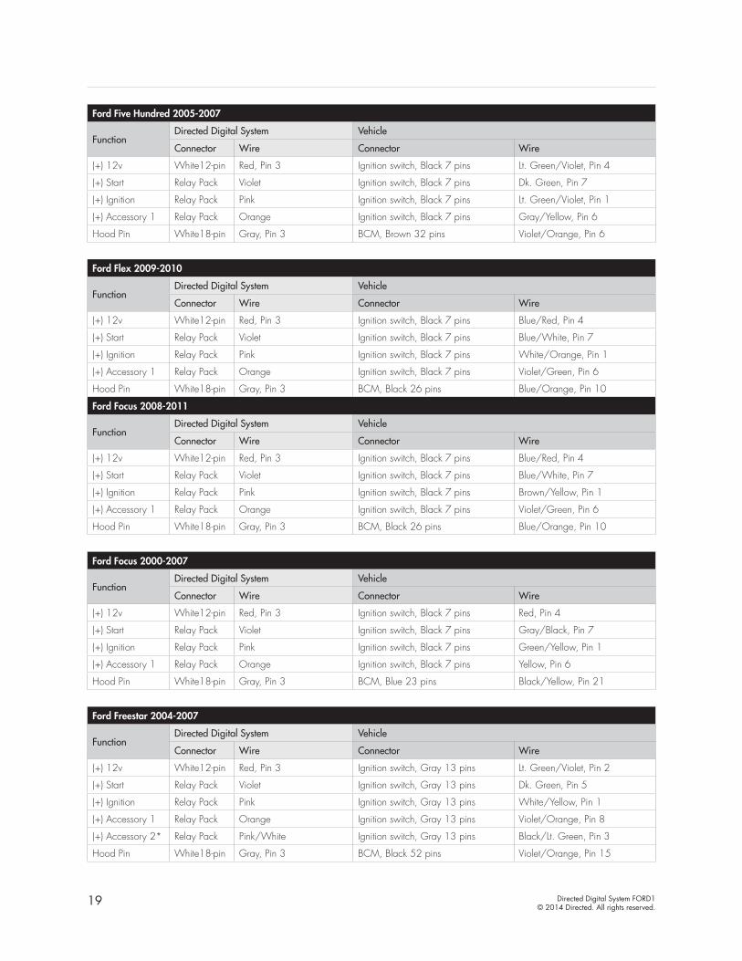
Ford Five Hundred 2005-2007
FunctionDirected Digital System Vehicle
Connector Wire Connector Wire
(+) 12v White12-pin Red, Pin 3 Ignition switch, Black 7 pins Lt. Green/Violet, Pin 4
(+) Start Relay Pack Violet Ignition switch, Black 7 pins Dk. Green, Pin 7
(+) Ignition Relay Pack Pink Ignition switch, Black 7 pins Lt. Green/Violet, Pin 1
(+) Accessory 1 Relay Pack Orange Ignition switch, Black 7 pins Gray/Yellow, Pin 6
Hood Pin White18-pin Gray, Pin 3 BCM, Brown 32 pins Violet/Orange, Pin 6
Ford Flex 2009-2010
FunctionDirected Digital System Vehicle
Connector Wire Connector Wire
(+) 12v White12-pin Red, Pin 3 Ignition switch, Black 7 pins Blue/Red, Pin 4
(+) Start Relay Pack Violet Ignition switch, Black 7 pins Blue/White, Pin 7
(+) Ignition Relay Pack Pink Ignition switch, Black 7 pins White/Orange, Pin 1
(+) Accessory 1 Relay Pack Orange Ignition switch, Black 7 pins Violet/Green, Pin 6
Hood Pin White18-pin Gray, Pin 3 BCM, Black 26 pins Blue/Orange, Pin 10
Ford Focus 2008-2011
FunctionDirected Digital System Vehicle
Connector Wire Connector Wire
(+) 12v White12-pin Red, Pin 3 Ignition switch, Black 7 pins Blue/Red, Pin 4
(+) Start Relay Pack Violet Ignition switch, Black 7 pins Blue/White, Pin 7
(+) Ignition Relay Pack Pink Ignition switch, Black 7 pins Brown/Yellow, Pin 1
(+) Accessory 1 Relay Pack Orange Ignition switch, Black 7 pins Violet/Green, Pin 6
Hood Pin White18-pin Gray, Pin 3 BCM, Black 26 pins Blue/Orange, Pin 10
Ford Focus 2000-2007
FunctionDirected Digital System Vehicle
Connector Wire Connector Wire
(+) 12v White12-pin Red, Pin 3 Ignition switch, Black 7 pins Red, Pin 4
(+) Start Relay Pack Violet Ignition switch, Black 7 pins Gray/Black, Pin 7
(+) Ignition Relay Pack Pink Ignition switch, Black 7 pins Green/Yellow, Pin 1
(+) Accessory 1 Relay Pack Orange Ignition switch, Black 7 pins Yellow, Pin 6
Hood Pin White18-pin Gray, Pin 3 BCM, Blue 23 pins Black/Yellow, Pin 21
Ford Freestar 2004-2007
FunctionDirected Digital System Vehicle
Connector Wire Connector Wire
(+) 12v White12-pin Red, Pin 3 Ignition switch, Gray 13 pins Lt. Green/Violet, Pin 2
(+) Start Relay Pack Violet Ignition switch, Gray 13 pins Dk. Green, Pin 5
(+) Ignition Relay Pack Pink Ignition switch, Gray 13 pins White/Yellow, Pin 1
(+) Accessory 1 Relay Pack Orange Ignition switch, Gray 13 pins Violet/Orange, Pin 8
(+) Accessory 2* Relay Pack Pink/White Ignition switch, Gray 13 pins Black/Lt. Green, Pin 3
Hood Pin White18-pin Gray, Pin 3 BCM, Black 52 pins Violet/Orange, Pin 15
20 Directed Digital System FORD1© 2014 Directed. All rights reserved.
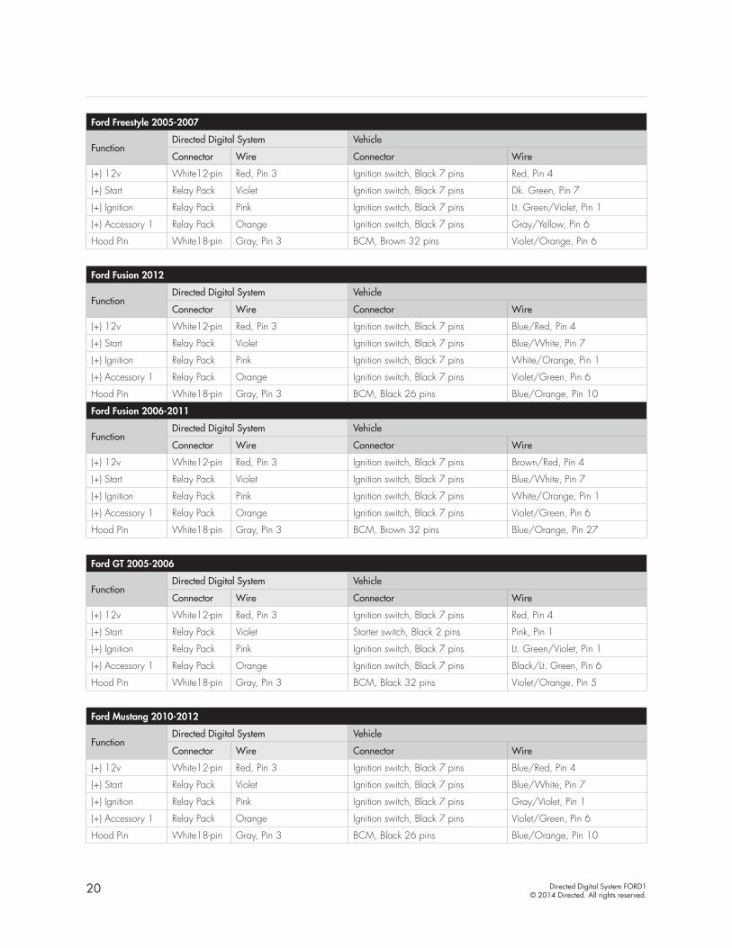
Ford Freestyle 2005-2007
FunctionDirected Digital System Vehicle
Connector Wire Connector Wire
(+) 12v White12-pin Red, Pin 3 Ignition switch, Black 7 pins Red, Pin 4
(+) Start Relay Pack Violet Ignition switch, Black 7 pins Dk. Green, Pin 7
(+) Ignition Relay Pack Pink Ignition switch, Black 7 pins Lt. Green/Violet, Pin 1
(+) Accessory 1 Relay Pack Orange Ignition switch, Black 7 pins Gray/Yellow, Pin 6
Hood Pin White18-pin Gray, Pin 3 BCM, Brown 32 pins Violet/Orange, Pin 6
Ford Fusion 2012
FunctionDirected Digital System Vehicle
Connector Wire Connector Wire
(+) 12v White12-pin Red, Pin 3 Ignition switch, Black 7 pins Blue/Red, Pin 4
(+) Start Relay Pack Violet Ignition switch, Black 7 pins Blue/White, Pin 7
(+) Ignition Relay Pack Pink Ignition switch, Black 7 pins White/Orange, Pin 1
(+) Accessory 1 Relay Pack Orange Ignition switch, Black 7 pins Violet/Green, Pin 6
Hood Pin White18-pin Gray, Pin 3 BCM, Black 26 pins Blue/Orange, Pin 10
Ford Fusion 2006-2011
FunctionDirected Digital System Vehicle
Connector Wire Connector Wire
(+) 12v White12-pin Red, Pin 3 Ignition switch, Black 7 pins Brown/Red, Pin 4
(+) Start Relay Pack Violet Ignition switch, Black 7 pins Blue/White, Pin 7
(+) Ignition Relay Pack Pink Ignition switch, Black 7 pins White/Orange, Pin 1
(+) Accessory 1 Relay Pack Orange Ignition switch, Black 7 pins Violet/Green, Pin 6
Hood Pin White18-pin Gray, Pin 3 BCM, Brown 32 pins Blue/Orange, Pin 27
Ford GT 2005-2006
FunctionDirected Digital System Vehicle
Connector Wire Connector Wire
(+) 12v White12-pin Red, Pin 3 Ignition switch, Black 7 pins Red, Pin 4
(+) Start Relay Pack Violet Starter switch, Black 2 pins Pink, Pin 1
(+) Ignition Relay Pack Pink Ignition switch, Black 7 pins Lt. Green/Violet, Pin 1
(+) Accessory 1 Relay Pack Orange Ignition switch, Black 7 pins Black/Lt. Green, Pin 6
Hood Pin White18-pin Gray, Pin 3 BCM, Black 32 pins Violet/Orange, Pin 5
Ford Mustang 2010-2012
FunctionDirected Digital System Vehicle
Connector Wire Connector Wire
(+) 12v White12-pin Red, Pin 3 Ignition switch, Black 7 pins Blue/Red, Pin 4
(+) Start Relay Pack Violet Ignition switch, Black 7 pins Blue/White, Pin 7
(+) Ignition Relay Pack Pink Ignition switch, Black 7 pins Gray/Violet, Pin 1
(+) Accessory 1 Relay Pack Orange Ignition switch, Black 7 pins Violet/Green, Pin 6
Hood Pin White18-pin Gray, Pin 3 BCM, Black 26 pins Blue/Orange, Pin 10

21 Directed Digital System FORD1© 2014 Directed. All rights reserved.
Ford Mustang 2005-2009
FunctionDirected Digital System Vehicle
Connector Wire Connector Wire
(+) 12v White12-pin Red, Pin 3 Ignition switch, Black 7 pins Lt. Green/Violet, Pin 4
(+) Start Relay Pack Violet Ignition switch, Black 7 pins Dk. Green, Pin 7
(+) Ignition Relay Pack Pink Ignition switch, Black 7 pins White/Yellow, Pin 1
(+) Accessory 1 Relay Pack Orange Ignition switch, Black 7 pins Black/Pink, Pin 6
Hood Pin White18-pin Gray, Pin 3 BCM, Black 52 pins Violet/Orange, Pin 15
Ford Ranger 2007-2012
FunctionDirected Digital System Vehicle
Connector Wire Connector Wire
(+) 12v White12-pin Red, Pin 3 Ignition switch, Gray 13 pins Red, Pin 2
(+) Start Relay Pack Violet Ignition switch, Gray 13 pins Blue/White, Pin 5
(+) Ignition Relay Pack Pink Ignition switch, Gray 13 pins White/Orange, Pin 1
(+) Accessory 1 Relay Pack Orange Ignition switch, Gray 13 pins Brown/Yellow, Pin 8
(+) Accessory 2* Relay Pack Pink/White Ignition switch, Gray 13 pins Violet/Green, Pin 3
Ford Ranger 2005-2006
FunctionDirected Digital System Vehicle
Connector Wire Connector Wire
(+) 12v White12-pin Red, Pin 3 Ignition switch, Black 13 pins Yellow, Pin 2
(+) Start Relay Pack Violet Ignition switch, Black 13 pins Red/Lt. Blue, Pin 5
(+) Ignition Relay Pack Pink Ignition switch, Black 13 pins Lt. Green/Violet, Pin 1
(+) Accessory 1 Relay Pack Orange Ignition switch, Black 13 pins Gray/Yellow, Pin 8
(+) Accessory 2* Relay Pack Pink/White Ignition switch, Black 13 pins Black/Lt. Green, Pin 3
Ford Ranger 2001-2004
FunctionDirected Digital System Vehicle
Connector Wire Connector Wire
(+) 12v White12-pin Red, Pin 3 Ignition switch, Black 15 pins Yellow, Pin B2
(+) Start Relay Pack Violet Ignition switch, Black 15 pins Red/Lt. Blue, Pin STA
(+) Ignition Relay Pack Pink Ignition switch, Black 15 pins Lt. Green/Violet, Pin I1
(+) Accessory 1 Relay Pack Orange Ignition switch, Black 15 pins Gray/Yellow, Pin A4
(+) Accessory 2* Relay Pack Pink/White Ignition switch, Black 15 pins Black/Lt. Green, Pin A1
Ford Sport Trac 2007-2010
FunctionDirected Digital System Vehicle
Connector Wire Connector Wire
(+) 12v White12-pin Red, Pin 3 Ignition switch, Black 7 pins Violet/Red, Pin 4
(+) Start Relay Pack Violet Ignition switch, Black 7 pins Blue/White, Pin 7
(+) Ignition Relay Pack Pink Ignition switch, Black 7 pins White/Orange, Pin 1
(+) Accessory 1 Relay Pack Orange Ignition switch, Black 7 pins Violet/Green, Pin 6

22 Directed Digital System FORD1© 2014 Directed. All rights reserved.
Ford Taurus 2010-2012
FunctionDirected Digital System Vehicle
Connector Wire Connector Wire
(+) 12v White12-pin Red, Pin 3 Ignition switch, Black 7 pins Blue/Red, Pin 4
(+) Start Relay Pack Violet Ignition switch, Black 7 pins Blue/White, Pin 7
(+) Ignition Relay Pack Pink Ignition switch, Black 7 pins Green/Violet, Pin 1
(+) Accessory 1 Relay Pack Orange Ignition switch, Black 7 pins Violet/Green, Pin 6
Hood Pin White18-pin Gray, Pin 3 BCM, Black 26 pins Blue/Orange, Pin 10
Ford Taurus 2008-2009
FunctionDirected Digital System Vehicle
Connector Wire Connector Wire
(+) 12v White12-pin Red, Pin 3 Ignition switch, Black 7 pins Red, Pin 4
(+) Start Relay Pack Violet Ignition switch, Black 7 pins Blue/White, Pin 7
(+) Ignition Relay Pack Pink Ignition switch, Black 7 pins White/Orange, Pin 1
(+) Accessory 1 Relay Pack Orange Ignition switch, Black 7 pins Violet/Green, Pin 6
Hood Pin White18-pin Gray, Pin 3 BCM, Black 26 pins Blue/Orange, Pin 10
Ford Taurus 2006-2007
FunctionDirected Digital System Vehicle
Connector Wire Connector Wire
(+) 12v White12-pin Red, Pin 3 Ignition switch, Black 13 pins Lt. Green/Violet, Pin 2
(+) Start Relay Pack Violet Ignition switch, Black 13 pins Red/Lt. Blue, Pin 5
(+) Ignition Relay Pack Pink Ignition switch, Black 13 pins Red/Lt. Green, Pin 1
(+) Accessory 1 Relay Pack Orange Ignition switch, Black 13 pins Gray/Yellow, Pin 8
Hood Pin White18-pin Gray, Pin 3 BCM, White 26 pins Tan/Lt. Green, Pin 17
Ford Taurus 2000-2005
FunctionDirected Digital System Vehicle
Connector Wire Connector Wire
(+) 12v White12-pin Red, Pin 3 Ignition switch, Black 15 pins Lt. Green/Violet, Pin B3
(+) Start Relay Pack Violet Ignition switch, Black 15 pins Red/Lt. Blue, Pin STA
(+) Ignition Relay Pack Pink Ignition switch, Black 15 pins Red/Lt. Green, Pin I1
(+) Accessory 1 Relay Pack Orange Ignition switch, Black 15 pins Gray/Yellow, Pin A4
(+) Accessory 2* Relay Pack Pink/White Ignition switch, Black 15 pins Black/Lt. Green, Pin A1
Hood Pin White18-pin Gray, Pin 3 BCM, White 26 pins Tan/Lt. Green, Pin 17
Ford Taurus X 2008-2009
FunctionDirected Digital System Vehicle
Connector Wire Connector Wire
(+) 12v White12-pin Red, Pin 3 Ignition switch, Black 7 pins Red, Pin 4
(+) Start Relay Pack Violet Ignition switch, Black 7 pins Blue/White, Pin 7
(+) Ignition Relay Pack Pink Ignition switch, Black 7 pins White/Orange, Pin 1
(+) Accessory 1 Relay Pack Orange Ignition switch, Black 7 pins Violet/Green, Pin 6
Hood Pin White18-pin Gray, Pin 3 BCM, Black 26 pins Blue/Orange, Pin 10
23 Directed Digital System FORD1© 2014 Directed. All rights reserved.
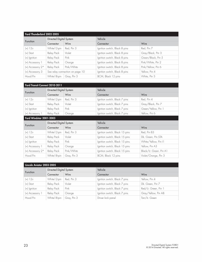
Ford Thunderbird 2002-2005
FunctionDirected Digital System Vehicle
Connector Wire Connector Wire
(+) 12v White12-pin Red, Pin 3 Ignition switch, Black 8 pins Red, Pin 7
(+) Start Relay Pack Violet Ignition switch, Black 8 pins Gray/Black, Pin 3
(+) Ignition Relay Pack Pink Ignition switch, Black 8 pins Green/Black, Pin 5
(+) Accessory 1 Relay Pack Orange Ignition switch, Black 8 pins Pink/White, Pin 2
(+) Accessory 2* Relay Pack Pink/White Ignition switch, Black 8 pins Pink/Yellow, Pin 6
(+) Accessory 3 See relay connection on page 10 Ignition switch, Black 8 pins Yellow, Pin 4
Hood Pin White18-pin Gray, Pin 3 BCM, Black 12 pins White, Pin 3
Ford Transit Connect 2010-2011
FunctionDirected Digital System Vehicle
Connector Wire Connector Wire
(+) 12v White12-pin Red, Pin 3 Ignition switch, Black 7 pins Red, Pin 4
(+) Start Relay Pack Violet Ignition switch, Black 7 pins Gray/Black, Pin 7
(+) Ignition Relay Pack Pink Ignition switch, Black 7 pins Green/Yellow, Pin 1
(+) Accessory 1 Relay Pack Orange Ignition switch, Black 7 pins Yellow, Pin 6
Ford Windstar 2001-2003
FunctionDirected Digital System Vehicle
Connector Wire Connector Wire
(+) 12v White12-pin Red, Pin 3 Ignition switch, Black 15 pins Red, Pin B3
(+) Start Relay Pack Violet Ignition switch, Black 15 pins Dk. Green, Pin STA
(+) Ignition Relay Pack Pink Ignition switch, Black 15 pins White/Yellow, Pin I1
(+) Accessory 1 Relay Pack Orange Ignition switch, Black 15 pins Yellow, Pin A3
(+) Accessory 2* Relay Pack Pink/White Ignition switch, Black 15 pins Black/Lt. Green, Pin A1
Hood Pin White18-pin Gray, Pin 3 BCM, Black 12 pins Violet/Orange, Pin 3
Lincoln Aviator 2003-2005
FunctionDirected Digital System Vehicle
Connector Wire Connector Wire
(+) 12v White12-pin Red, Pin 3 Ignition switch, Black 7 pins Yellow, Pin 4
(+) Start Relay Pack Violet Ignition switch, Black 7 pins Dk. Green, Pin 7
(+) Ignition Relay Pack Pink Ignition switch, Black 7 pins Red/Lt. Green, Pin 1
(+) Accessory 1 Relay Pack Orange Ignition switch, Black 7 pins Gray/Yellow, Pin A8
Hood Pin White18-pin Gray, Pin 3 Driver kick panel Tan/Lt. Green

24 Directed Digital System FORD1© 2014 Directed. All rights reserved.
Lincoln LS 2000-2006
FunctionDirected Digital System Vehicle
Connector Wire Connector Wire
(+) 12v White12-pin Red, Pin 3 Ignition switch, Black 8 pins Red, Pin 7
(+) Start Relay Pack Violet Ignition switch, Black 8 pins Gray/Black, Pin 3
(+) Ignition Relay Pack Pink Ignition switch, Black 8 pins Green/Black, Pin 5
(+) Accessory 1 Relay Pack Orange Ignition switch, Black 8 pins Pink/White, Pin 2
(+) Accessory 2* Relay Pack Pink/White Ignition switch, Black 8 pins Pink/Yellow, Pin 6
(+) Accessory 3 See relay connection on page 10 Ignition switch, Black 8 pins Yellow, Pin 4
Hood Pin White18-pin Gray, Pin 3 BCM, Black 12 pins White, Pin 3
Lincoln Mark LT 2006-2008
FunctionDirected Digital System Vehicle
Connector Wire Connector Wire
(+) 12v White12-pin Red, Pin 3 Ignition switch, Black 7 pins Lt. Green/Violet, Pin 4
(+) Start Relay Pack Violet Ignition switch, Black 7 pins Red/Lt. Blue, Pin 7
(+) Ignition Relay Pack Pink Ignition switch, Black 7 pins Dk. Blue/Lt. Green, Pin 1
(+) Accessory 1 Relay Pack Orange Ignition switch, Black 7 pins Black/Lt. Green, Pin 6
Lincoln MKS 2009-2012
FunctionDirected Digital System Vehicle
Connector Wire Connector Wire
(+) 12v White12-pin Red, Pin 3 Ignition switch, Black 7 pins Blue/Red, Pin 4
(+) Start Relay Pack Violet Ignition switch, Black 7 pins Blue/White, Pin 7
(+) Ignition Relay Pack Pink Ignition switch, Black 7 pins White/Orange, Pin 1
(+) Accessory 1 Relay Pack Orange Ignition switch, Black 7 pins Violet/Green, Pin 6
Hood Pin White18-pin Gray, Pin 3 BCM, Black 26 pins Blue/Orange, Pin 10
Lincoln MKX 2007-2010
FunctionDirected Digital System Vehicle
Connector Wire Connector Wire
(+) 12v White12-pin Red, Pin 3 Ignition switch, Black 7 pins Blue/Red, Pin 4
(+) Start Relay Pack Violet Ignition switch, Black 7 pins Blue/White, Pin 7
(+) Ignition Relay Pack Pink Ignition switch, Black 7 pins White/Orange, Pin 1
(+) Accessory 1 Relay Pack Orange Ignition switch, Black 7 pins Violet/Green, Pin 6
Hood Pin White18-pin Gray, Pin 3 BCM, Black 26 pins Blue/Orange, Pin 10
Lincoln MKZ 2010-2012
FunctionDirected Digital System Vehicle
Connector Wire Connector Wire
(+) 12v White12-pin Red, Pin 3 Ignition switch, Black 7 pins Blue/Red, Pin 4
(+) Start Relay Pack Violet Ignition switch, Black 7 pins Blue/White, Pin 7
(+) Ignition Relay Pack Pink Ignition switch, Black 7 pins White/Orange, Pin 1
(+) Accessory 1 Relay Pack Orange Ignition switch, Black 7 pins Violet/Green, Pin 6
Hood Pin White18-pin Gray, Pin 3 BCM, Black 26 pins Blue/Orange, Pin 10
25 Directed Digital System FORD1© 2014 Directed. All rights reserved.
Lincoln MKZ 2007-2009
FunctionDirected Digital System Vehicle
Connector Wire Connector Wire
(+) 12v White12-pin Red, Pin 3 Ignition switch, Black 7 pins Brown/Red, Pin 4
(+) Start Relay Pack Violet Ignition switch, Black 7 pins Blue/White, Pin 7
(+) Ignition Relay Pack Pink Ignition switch, Black 7 pins White/Orange, Pin 1
(+) Accessory 1 Relay Pack Orange Ignition switch, Black 7 pins Violet/Green, Pin 6
Hood Pin White18-pin Gray, Pin 3 BCM, Brown 32 pins Blue/Orange, Pin 27
Lincoln Navigator 2007-2012
FunctionDirected Digital System Vehicle
Connector Wire Connector Wire
(+) 12v White12-pin Red, Pin 3 Ignition switch, Gray 10 pins Blue/Red, Pin 9
(+) Start Relay Pack Violet Ignition switch, Gray 10 pins Blue/White, Pin 10
(+) Ignition Relay Pack Pink Ignition switch, Gray 10 pins White/Orange, Pin 1
(+) Accessory 1 Relay Pack Orange Ignition switch, Gray 10 pins Brown/Yellow, Pin 7
(+) Accessory 2* Relay Pack Pink/White Ignition switch, Gray 10 pins Violet/Green, Pin 5
Hood Pin White18-pin Gray, Pin 3 BCM, Black 26 pins Blue/Orange, Pin 10
Lincoln Navigator 2002-2006
FunctionDirected Digital System Vehicle
Connector Wire Connector Wire
(+) 12v White12-pin Red, Pin 3 Ignition switch, Black 7 pins Lt. Green/Violet, Pin 4
(+) Start Relay Pack Violet Ignition switch, Black 7 pins Red/Lt. Blue, Pin 7
(+) Ignition Relay Pack Pink Ignition switch, Black 7 pins Dk. Blue/Lt. Green, Pin 1
(+) Accessory 1 Relay Pack Orange Ignition switch, Black 7 pins Black/Lt. Green, Pin 6
Lincoln Town Car 2005-2011
FunctionDirected Digital System Vehicle
Connector Wire Connector Wire
(+) 12v White12-pin Red, Pin 3 Ignition switch, Gray 10 pins Lt. Green/Violet or Red, Pin 9
(+) Start Relay Pack Violet Ignition switch, Gray 10 pins Dk. Green, Pin 10
(+) Ignition Relay Pack Pink Ignition switch, Gray 10 pins Violet/Orange, Pin 1
(+) Accessory 1 Relay Pack Orange Ignition switch, Gray 10 pins Gray/Yellow, Pin 7
(+) Accessory 2* Relay Pack Pink/White Ignition switch, Gray 10 pins White/Violet, Pin 5
Hood Pin White18-pin Gray, Pin 3 BCM, Black 16 pins Violet/Orange, Pin 2
Lincoln Town Car 2003-2004
FunctionDirected Digital System Vehicle
Connector Wire Connector Wire
(+) 12v White12-pin Red, Pin 3 Ignition switch, Black 15 pins Yellow, Pin B3
(+) Start Relay Pack Violet Ignition switch, Black 15 pins Red/Lt. Blue, Pin STA
(+) Ignition Relay Pack Pink Ignition switch, Black 15 pins White/Yellow, Pin I1
(+) Accessory 1 Relay Pack Orange Ignition switch, Black 15 pins Gray/Yellow, Pin A4
(+) Accessory 2* Relay Pack Pink/White Ignition switch, Black 15 pins Pink/Black, Pin A2
(+) Accessory 3 See relay connection on page 10 Ignition switch, Black 15 pins Black/Lt. Green, Pin A1
Hood Pin White18-pin Gray, Pin 3 BCM, White 16 pins Violet/Orange, Pin 2
26 Directed Digital System FORD1© 2014 Directed. All rights reserved.
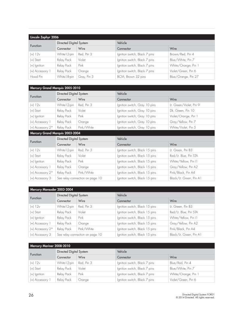
Lincoln Zephyr 2006
FunctionDirected Digital System Vehicle
Connector Wire Connector Wire
(+) 12v White12-pin Red, Pin 3 Ignition switch, Black 7 pins Brown/Red, Pin 4
(+) Start Relay Pack Violet Ignition switch, Black 7 pins Blue/White, Pin 7
(+) Ignition Relay Pack Pink Ignition switch, Black 7 pins White/Orange, Pin 1
(+) Accessory 1 Relay Pack Orange Ignition switch, Black 7 pins Violet/Green, Pin 6
Hood Pin White18-pin Gray, Pin 3 BCM, Brown 32 pins Blue/Orange, Pin 27
Mercury Grand Marquis 2005-2010
FunctionDirected Digital System Vehicle
Connector Wire Connector Wire
(+) 12v White12-pin Red, Pin 3 Ignition switch, Gray 10 pins Lt. Green/Violet, Pin 9
(+) Start Relay Pack Violet Ignition switch, Gray 10 pins Dk. Green, Pin 10
(+) Ignition Relay Pack Pink Ignition switch, Gray 10 pins Violet/Orange, Pin 1
(+) Accessory 1 Relay Pack Orange Ignition switch, Gray 10 pins Gray/Yellow, Pin 7
(+) Accessory 2* Relay Pack Pink/White Ignition switch, Gray 10 pins White/Violet, Pin 5
Mercury Grand Marquis 2003-2004
FunctionDirected Digital System Vehicle
Connector Wire Connector Wire
(+) 12v White12-pin Red, Pin 3 Ignition switch, Black 15 pins Lt. Green, Pin B3
(+) Start Relay Pack Violet Ignition switch, Black 15 pins Red/Lt. Blue, Pin STA
(+) Ignition Relay Pack Pink Ignition switch, Black 15 pins White/Yellow, Pin I1
(+) Accessory 1 Relay Pack Orange Ignition switch, Black 15 pins Gray/Yellow, Pin A2
(+) Accessory 2* Relay Pack Pink/White Ignition switch, Black 15 pins Pink/Black, Pin A4
(+) Accessory 3 See relay connection on page 10 Ignition switch, Black 15 pins Black/Lt. Green, Pin A1
Mercury Marauder 2003-2004
FunctionDirected Digital System Vehicle
Connector Wire Connector Wire
(+) 12v White12-pin Red, Pin 3 Ignition switch, Black 15 pins Lt. Green, Pin B3
(+) Start Relay Pack Violet Ignition switch, Black 15 pins Red/Lt. Blue, Pin STA
(+) Ignition Relay Pack Pink Ignition switch, Black 15 pins White/Yellow, Pin I1
(+) Accessory 1 Relay Pack Orange Ignition switch, Black 15 pins Gray/Yellow, Pin A2
(+) Accessory 2* Relay Pack Pink/White Ignition switch, Black 15 pins Pink/Black, Pin A4
(+) Accessory 3 See relay connection on page 10 Ignition switch, Black 15 pins Black/Lt. Green, Pin A1
Mercury Mariner 2008-2010
FunctionDirected Digital System Vehicle
Connector Wire Connector Wire
(+) 12v White12-pin Red, Pin 3 Ignition switch, Black 7 pins Blue/Red, Pin 4
(+) Start Relay Pack Violet Ignition switch, Black 7 pins Blue/White, Pin 7
(+) Ignition Relay Pack Pink Ignition switch, Black 7 pins White/Orange, Pin 1
(+) Accessory 1 Relay Pack Orange Ignition switch, Black 7 pins Violet/Green, Pin 6
27 Directed Digital System FORD1© 2014 Directed. All rights reserved.
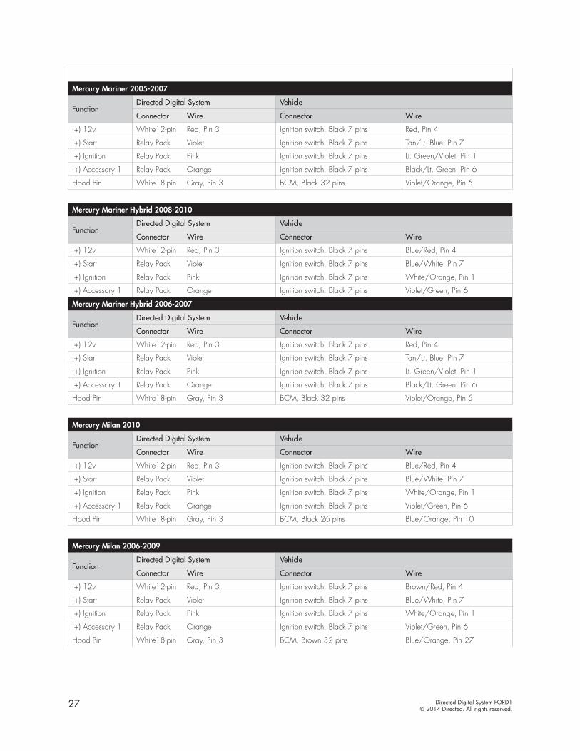
Mercury Mariner 2005-2007
FunctionDirected Digital System Vehicle
Connector Wire Connector Wire
(+) 12v White12-pin Red, Pin 3 Ignition switch, Black 7 pins Red, Pin 4
(+) Start Relay Pack Violet Ignition switch, Black 7 pins Tan/Lt. Blue, Pin 7
(+) Ignition Relay Pack Pink Ignition switch, Black 7 pins Lt. Green/Violet, Pin 1
(+) Accessory 1 Relay Pack Orange Ignition switch, Black 7 pins Black/Lt. Green, Pin 6
Hood Pin White18-pin Gray, Pin 3 BCM, Black 32 pins Violet/Orange, Pin 5
Mercury Mariner Hybrid 2008-2010
FunctionDirected Digital System Vehicle
Connector Wire Connector Wire
(+) 12v White12-pin Red, Pin 3 Ignition switch, Black 7 pins Blue/Red, Pin 4
(+) Start Relay Pack Violet Ignition switch, Black 7 pins Blue/White, Pin 7
(+) Ignition Relay Pack Pink Ignition switch, Black 7 pins White/Orange, Pin 1
(+) Accessory 1 Relay Pack Orange Ignition switch, Black 7 pins Violet/Green, Pin 6
Mercury Mariner Hybrid 2006-2007
FunctionDirected Digital System Vehicle
Connector Wire Connector Wire
(+) 12v White12-pin Red, Pin 3 Ignition switch, Black 7 pins Red, Pin 4
(+) Start Relay Pack Violet Ignition switch, Black 7 pins Tan/Lt. Blue, Pin 7
(+) Ignition Relay Pack Pink Ignition switch, Black 7 pins Lt. Green/Violet, Pin 1
(+) Accessory 1 Relay Pack Orange Ignition switch, Black 7 pins Black/Lt. Green, Pin 6
Hood Pin White18-pin Gray, Pin 3 BCM, Black 32 pins Violet/Orange, Pin 5
Mercury Milan 2010
FunctionDirected Digital System Vehicle
Connector Wire Connector Wire
(+) 12v White12-pin Red, Pin 3 Ignition switch, Black 7 pins Blue/Red, Pin 4
(+) Start Relay Pack Violet Ignition switch, Black 7 pins Blue/White, Pin 7
(+) Ignition Relay Pack Pink Ignition switch, Black 7 pins White/Orange, Pin 1
(+) Accessory 1 Relay Pack Orange Ignition switch, Black 7 pins Violet/Green, Pin 6
Hood Pin White18-pin Gray, Pin 3 BCM, Black 26 pins Blue/Orange, Pin 10
Mercury Milan 2006-2009
FunctionDirected Digital System Vehicle
Connector Wire Connector Wire
(+) 12v White12-pin Red, Pin 3 Ignition switch, Black 7 pins Brown/Red, Pin 4
(+) Start Relay Pack Violet Ignition switch, Black 7 pins Blue/White, Pin 7
(+) Ignition Relay Pack Pink Ignition switch, Black 7 pins White/Orange, Pin 1
(+) Accessory 1 Relay Pack Orange Ignition switch, Black 7 pins Violet/Green, Pin 6
Hood Pin White18-pin Gray, Pin 3 BCM, Brown 32 pins Blue/Orange, Pin 27
28 Directed Digital System FORD1© 2014 Directed. All rights reserved.
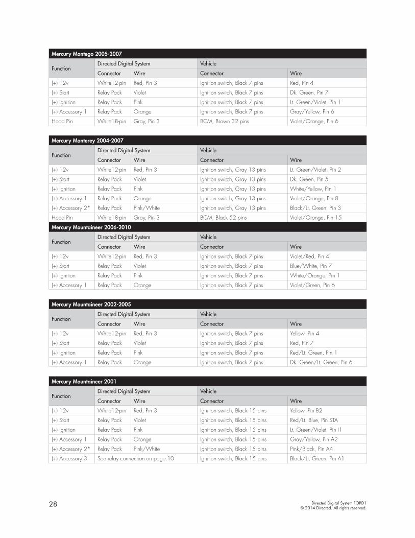
Mercury Montego 2005-2007
FunctionDirected Digital System Vehicle
Connector Wire Connector Wire
(+) 12v White12-pin Red, Pin 3 Ignition switch, Black 7 pins Red, Pin 4
(+) Start Relay Pack Violet Ignition switch, Black 7 pins Dk. Green, Pin 7
(+) Ignition Relay Pack Pink Ignition switch, Black 7 pins Lt. Green/Violet, Pin 1
(+) Accessory 1 Relay Pack Orange Ignition switch, Black 7 pins Gray/Yellow, Pin 6
Hood Pin White18-pin Gray, Pin 3 BCM, Brown 32 pins Violet/Orange, Pin 6
Mercury Monterey 2004-2007
FunctionDirected Digital System Vehicle
Connector Wire Connector Wire
(+) 12v White12-pin Red, Pin 3 Ignition switch, Gray 13 pins Lt. Green/Violet, Pin 2
(+) Start Relay Pack Violet Ignition switch, Gray 13 pins Dk. Green, Pin 5
(+) Ignition Relay Pack Pink Ignition switch, Gray 13 pins White/Yellow, Pin 1
(+) Accessory 1 Relay Pack Orange Ignition switch, Gray 13 pins Violet/Orange, Pin 8
(+) Accessory 2* Relay Pack Pink/White Ignition switch, Gray 13 pins Black/Lt. Green, Pin 3
Hood Pin White18-pin Gray, Pin 3 BCM, Black 52 pins Violet/Orange, Pin 15
Mercury Mountaineer 2006-2010
FunctionDirected Digital System Vehicle
Connector Wire Connector Wire
(+) 12v White12-pin Red, Pin 3 Ignition switch, Black 7 pins Violet/Red, Pin 4
(+) Start Relay Pack Violet Ignition switch, Black 7 pins Blue/White, Pin 7
(+) Ignition Relay Pack Pink Ignition switch, Black 7 pins White/Orange, Pin 1
(+) Accessory 1 Relay Pack Orange Ignition switch, Black 7 pins Violet/Green, Pin 6
Mercury Mountaineer 2002-2005
FunctionDirected Digital System Vehicle
Connector Wire Connector Wire
(+) 12v White12-pin Red, Pin 3 Ignition switch, Black 7 pins Yellow, Pin 4
(+) Start Relay Pack Violet Ignition switch, Black 7 pins Red, Pin 7
(+) Ignition Relay Pack Pink Ignition switch, Black 7 pins Red/Lt. Green, Pin 1
(+) Accessory 1 Relay Pack Orange Ignition switch, Black 7 pins Dk. Green/Lt. Green, Pin 6
Mercury Mountaineer 2001
FunctionDirected Digital System Vehicle
Connector Wire Connector Wire
(+) 12v White12-pin Red, Pin 3 Ignition switch, Black 15 pins Yellow, Pin B2
(+) Start Relay Pack Violet Ignition switch, Black 15 pins Red/Lt. Blue, Pin STA
(+) Ignition Relay Pack Pink Ignition switch, Black 15 pins Lt. Green/Violet, Pin I1
(+) Accessory 1 Relay Pack Orange Ignition switch, Black 15 pins Gray/Yellow, Pin A2
(+) Accessory 2* Relay Pack Pink/White Ignition switch, Black 15 pins Pink/Black, Pin A4
(+) Accessory 3 See relay connection on page 10 Ignition switch, Black 15 pins Black/Lt. Green, Pin A1
29 Directed Digital System FORD1© 2014 Directed. All rights reserved.
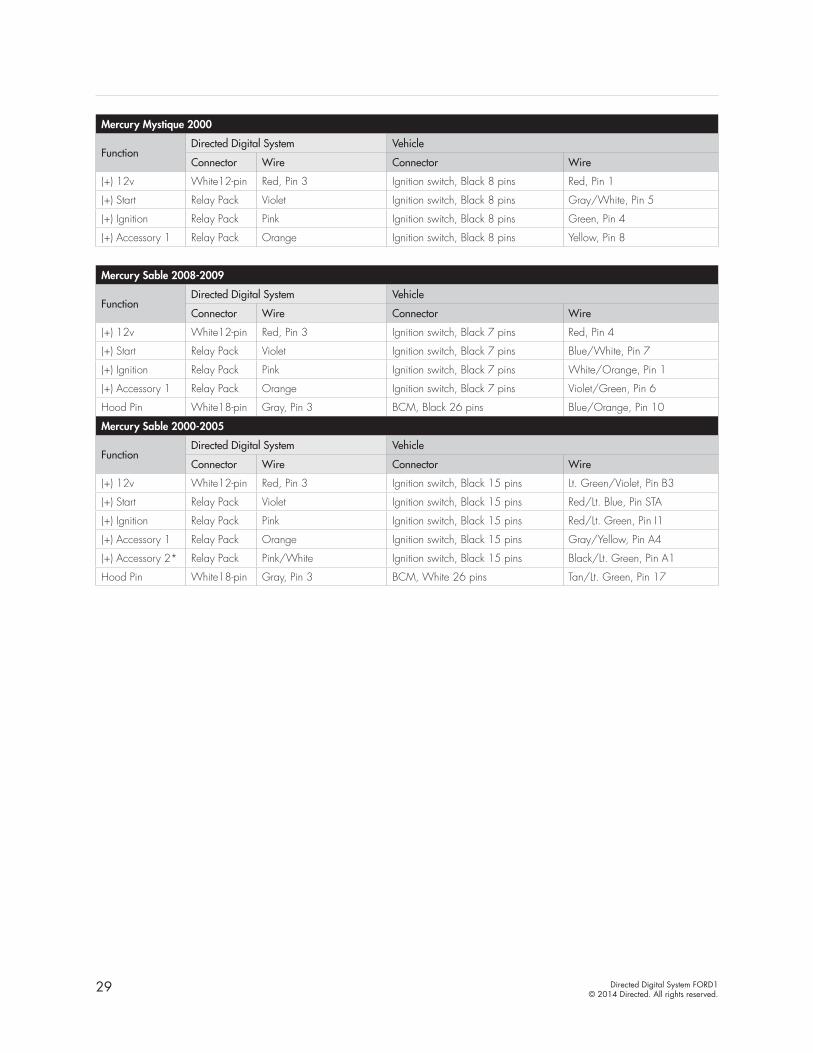
Mercury Mystique 2000
FunctionDirected Digital System Vehicle
Connector Wire Connector Wire
(+) 12v White12-pin Red, Pin 3 Ignition switch, Black 8 pins Red, Pin 1
(+) Start Relay Pack Violet Ignition switch, Black 8 pins Gray/White, Pin 5
(+) Ignition Relay Pack Pink Ignition switch, Black 8 pins Green, Pin 4
(+) Accessory 1 Relay Pack Orange Ignition switch, Black 8 pins Yellow, Pin 8
Mercury Sable 2008-2009
FunctionDirected Digital System Vehicle
Connector Wire Connector Wire
(+) 12v White12-pin Red, Pin 3 Ignition switch, Black 7 pins Red, Pin 4
(+) Start Relay Pack Violet Ignition switch, Black 7 pins Blue/White, Pin 7
(+) Ignition Relay Pack Pink Ignition switch, Black 7 pins White/Orange, Pin 1
(+) Accessory 1 Relay Pack Orange Ignition switch, Black 7 pins Violet/Green, Pin 6
Hood Pin White18-pin Gray, Pin 3 BCM, Black 26 pins Blue/Orange, Pin 10
Mercury Sable 2000-2005
FunctionDirected Digital System Vehicle
Connector Wire Connector Wire
(+) 12v White12-pin Red, Pin 3 Ignition switch, Black 15 pins Lt. Green/Violet, Pin B3
(+) Start Relay Pack Violet Ignition switch, Black 15 pins Red/Lt. Blue, Pin STA
(+) Ignition Relay Pack Pink Ignition switch, Black 15 pins Red/Lt. Green, Pin I1
(+) Accessory 1 Relay Pack Orange Ignition switch, Black 15 pins Gray/Yellow, Pin A4
(+) Accessory 2* Relay Pack Pink/White Ignition switch, Black 15 pins Black/Lt. Green, Pin A1
Hood Pin White18-pin Gray, Pin 3 BCM, White 26 pins Tan/Lt. Green, Pin 17
30 Directed Digital System FORD1© 2014 Directed. All rights reserved.
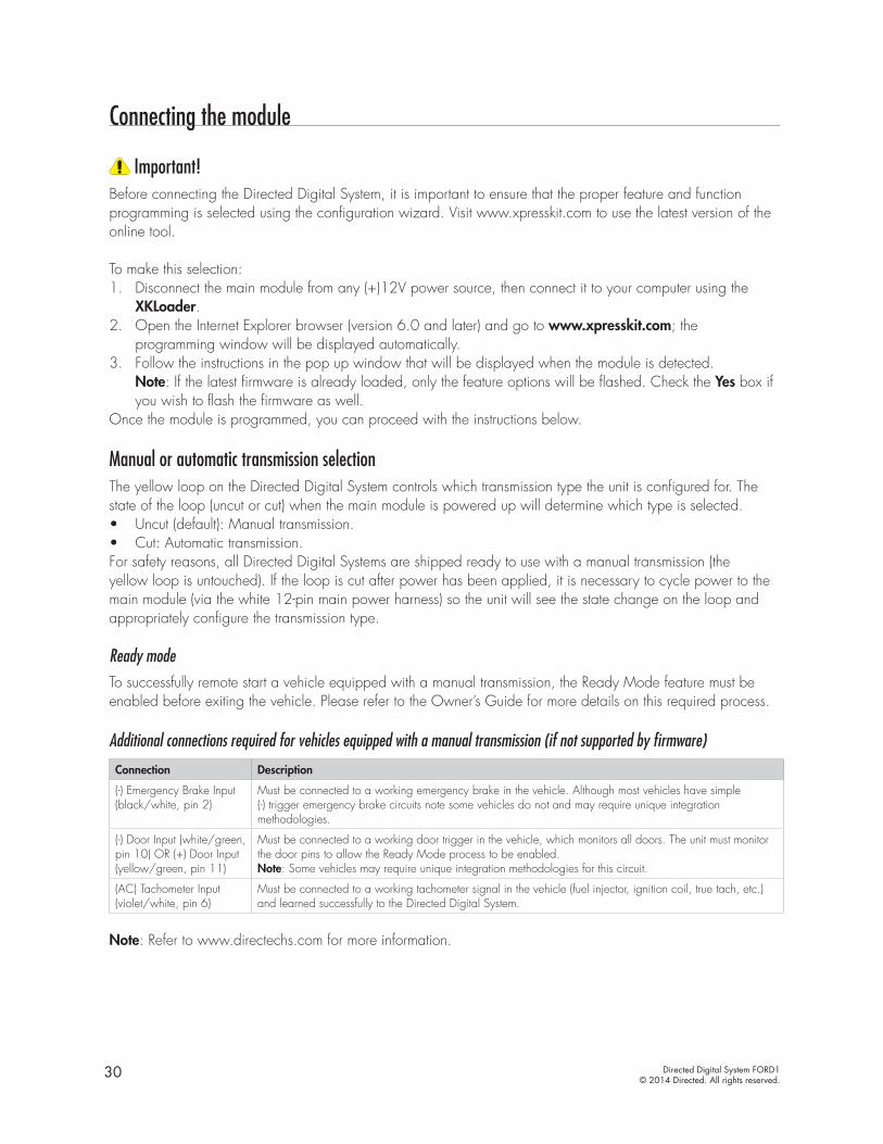
Connecting the module
Important!Before connecting the Directed Digital System, it is important to ensure that the proper feature and function programming is selected using the configuration wizard. Visit www.xpresskit.com to use the latest version of the online tool.
To make this selection:1. Disconnect the main module from any (+)12V power source, then connect it to your computer using the
XKLoader.2. Open the Internet Explorer browser (version 6.0 and later) and go to www.xpresskit.com; the
programming window will be displayed automatically.3. Follow the instructions in the pop up window that will be displayed when the module is detected.
Note: If the latest firmware is already loaded, only the feature options will be flashed. Check the Yes box if you wish to flash the firmware as well.
Once the module is programmed, you can proceed with the instructions below.
Manual or automatic transmission selectionThe yellow loop on the Directed Digital System controls which transmission type the unit is configured for. The state of the loop (uncut or cut) when the main module is powered up will determine which type is selected.• Uncut (default): Manual transmission.• Cut: Automatic transmission.For safety reasons, all Directed Digital Systems are shipped ready to use with a manual transmission (the yellow loop is untouched). If the loop is cut after power has been applied, it is necessary to cycle power to the main module (via the white 12-pin main power harness) so the unit will see the state change on the loop and appropriately configure the transmission type.
Ready modeTo successfully remote start a vehicle equipped with a manual transmission, the Ready Mode feature must be enabled before exiting the vehicle. Please refer to the Owner’s Guide for more details on this required process. Additional connections required for vehicles equipped with a manual transmission (if not supported by firmware)
Connection Description
(-) Emergency Brake Input (black/white, pin 2)
Must be connected to a working emergency brake in the vehicle. Although most vehicles have simple (-) trigger emergency brake circuits note some vehicles do not and may require unique integration methodologies.
(-) Door Input (white/green, pin 10) OR (+) Door Input (yellow/green, pin 11)
Must be connected to a working door trigger in the vehicle, which monitors all doors. The unit must monitor the door pins to allow the Ready Mode process to be enabled.Note: Some vehicles may require unique integration methodologies for this circuit.
(AC) Tachometer Input (violet/white, pin 6)
Must be connected to a working tachometer signal in the vehicle (fuel injector, ignition coil, true tach, etc.) and learned successfully to the Directed Digital System.
Note: Refer to www.directechs.com for more information.
31 Directed Digital System FORD1© 2014 Directed. All rights reserved.
Optional sensorsNote: The sensor port is only active on hybrid systems.
The 4-pin sensor port is compatible with a number of different Directed sensors including, but not limited to:• Shock Sensor – 504D• Field Disturbance Sensor – 508D• Ultrasonic Sensor – 509U
Note: In the case of 508D, power and ground must be hardwired to the vehicle – power and ground should NOT be obtained from the 4-pin sensor port.
Each sensor will have its own instructions, which must be followed for installation and adjustment.
RF kitsAn RF kit consists of one or multiple remotes, a Control Center (antenna), and an antenna cable – various combinations exist. An RF kit allows the vehicle owner to control the system with enhanced range. Two-way models are available. Please follow the instructions included with the kit for appropriate installation and programming information.
When flashing the Directed Digital System, make sure to pick the remote you will be using. This way the main module will have the necessary firmware to interact with the remote and Control Center (antenna) combination.
When used in conjunction with SmartStartThe Directed Digital System main module must be disconnected from any power source before SmartStart can be connected to it. Failing to do so could damage main module.
To ensure that the D2D communication between the Directed Digital System and SmartStart works properly, one of the following actions must be executed, depending on the hardware you are using:• Rev A SmartStart – The brown or blue loop must be cut. • Rev B SmartStart – The gray wire must be connected to a ground source.
Do NOT connect the SmartStart 2-pin power harness. Power and ground will be provided by the D2D connector on main module.
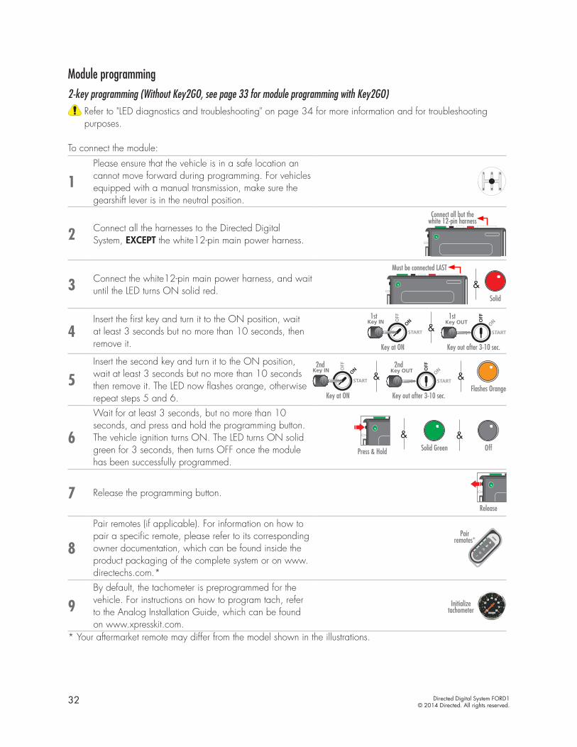
32 Directed Digital System FORD1© 2014 Directed. All rights reserved.
Module programming 2-key programming (Without Key2GO, see page 33 for module programming with Key2GO)
Refer to "LED diagnostics and troubleshooting" on page 34 for more information and for troubleshooting purposes.
To connect the module:
1Please ensure that the vehicle is in a safe location an cannot move forward during programming. For vehicles equipped with a manual transmission, make sure the gearshift lever is in the neutral position.
2 Connect all the harnesses to the Directed Digital System, EXCEPT the white12-pin main power harness.
Connect all but the white 12-pin harness
3 Connect the white12-pin main power harness, and wait until the LED turns ON solid red.
Must be connected LAST
&Solid
4Insert the first key and turn it to the ON position, wait at least 3 seconds but no more than 10 seconds, then remove it.
&START
Key OUT ONOFF
START
Key IN ONOFF
START
Key IN ONOFF
START
Key IN ONOFF
START
Key OUT ONOFF
START
Key IN ONOFF
START
Key IN ONOFF
START
Key IN ONOFF
1st
START
Key OUT ONOFF
START
Key IN ONOFF
START
Key IN ONOFF
START
Key IN ONOFF
START
Key OUT ONOFF
START
Key IN ONOFF
START
Key IN ONOFF
START
Key IN ONOFF
1st
Key at ON Key out after 3-10 sec.
5Insert the second key and turn it to the ON position, wait at least 3 seconds but no more than 10 seconds then remove it. The LED now flashes orange, otherwise repeat steps 5 and 6.
& &START
Key OUT ONOFF
START
Key IN ONOFF
START
Key IN ONOFF
START
Key IN ONOFF
START
Key OUT ONOFF
START
Key IN ONOFF
START
Key IN ONOFF
START
Key IN ONOFF
2nd
START
Key OUT ONOFF
START
Key IN ONOFF
START
Key IN ONOFF
START
Key IN ONOFF
START
Key OUT ONOFF
START
Key IN ONOFF
START
Key IN ONOFF
START
Key IN ONOFF
2nd
Key at ON Key out after 3-10 sec.Flashes Orange
6
Wait for at least 3 seconds, but no more than 10 seconds, and press and hold the programming button.The vehicle ignition turns ON. The LED turns ON solid green for 3 seconds, then turns OFF once the module has been successfully programmed.
&Solid Green OffPress & Hold
&
7 Release the programming button.Release
8
Pair remotes (if applicable). For information on how to pair a specific remote, please refer to its corresponding owner documentation, which can be found inside the product packaging of the complete system or on www.directechs.com.*
Pair remotes*
9By default, the tachometer is preprogrammed for the vehicle. For instructions on how to program tach, refer to the Analog Installation Guide, which can be found on www.xpresskit.com.
Initialize tachometer
* Your aftermarket remote may differ from the model shown in the illustrations.
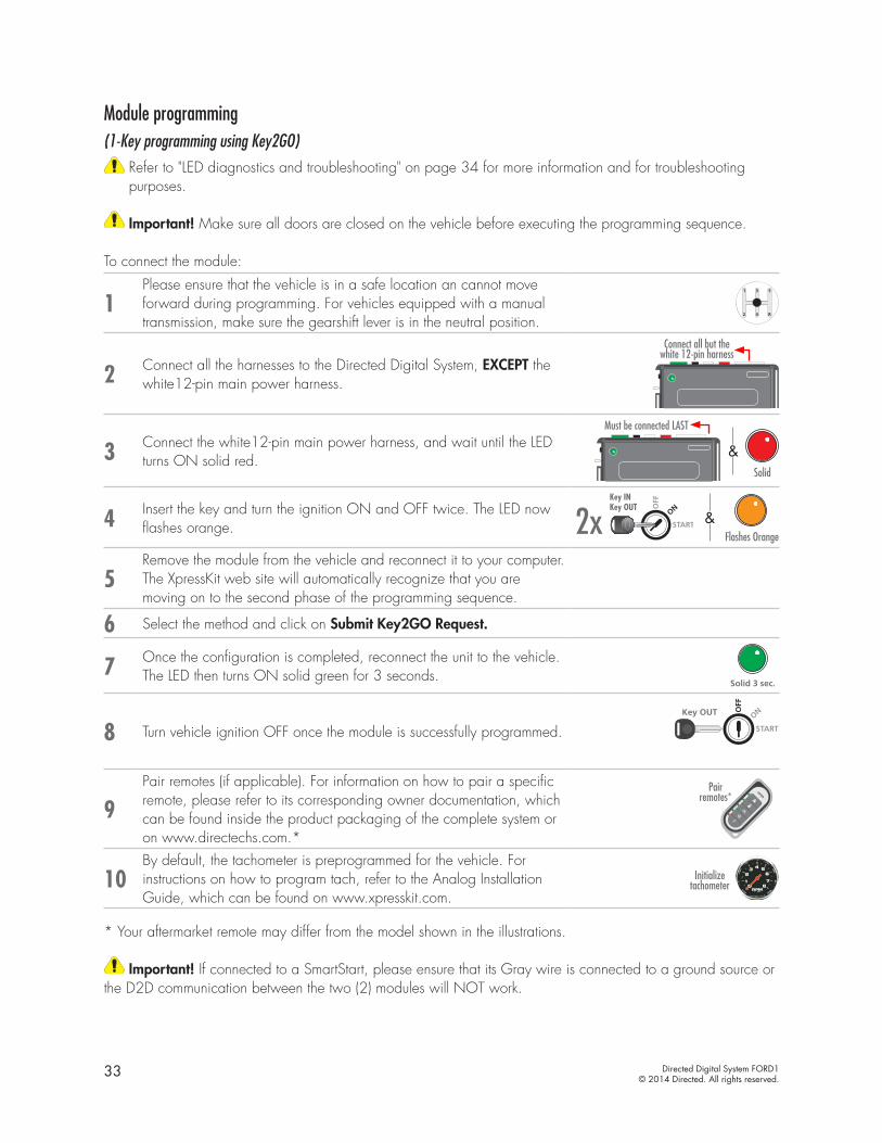
33 Directed Digital System FORD1© 2014 Directed. All rights reserved.
Module programming (1-Key programming using Key2GO)
Refer to "LED diagnostics and troubleshooting" on page 34 for more information and for troubleshooting purposes.
Important! Make sure all doors are closed on the vehicle before executing the programming sequence.
To connect the module:
1Please ensure that the vehicle is in a safe location an cannot move forward during programming. For vehicles equipped with a manual transmission, make sure the gearshift lever is in the neutral position.
2 Connect all the harnesses to the Directed Digital System, EXCEPT the white12-pin main power harness.
Connect all but the white 12-pin harness
3 Connect the white12-pin main power harness, and wait until the LED turns ON solid red.
Must be connected LAST
&Solid
4 Insert the key and turn the ignition ON and OFF twice. The LED now flashes orange.
&Flashes Orange
START
Key OUT ONOFF
START
Key IN ONOFF
START
Key IN ONOFF
START
Key IN ONOFF
START
Key OUT ONOFF
START
Key IN ONOFF
START
Key IN ONOFF
START
Key IN ONOFF
2xKey INKey OUT
5Remove the module from the vehicle and reconnect it to your computer. The XpressKit web site will automatically recognize that you are moving on to the second phase of the programming sequence.
6 Select the method and click on Submit Key2GO Request.
7 Once the configuration is completed, reconnect the unit to the vehicle. The LED then turns ON solid green for 3 seconds.
Solid 3 sec.
8 Turn vehicle ignition OFF once the module is successfully programmed. START
Key OUT ONOFF
START
Key IN ONOFF
START
Key IN ONOFF
START
Key IN ONOFF
9Pair remotes (if applicable). For information on how to pair a specific remote, please refer to its corresponding owner documentation, which can be found inside the product packaging of the complete system or on www.directechs.com.*
Pair remotes*
10By default, the tachometer is preprogrammed for the vehicle. For instructions on how to program tach, refer to the Analog Installation Guide, which can be found on www.xpresskit.com.
Initialize tachometer
* Your aftermarket remote may differ from the model shown in the illustrations.
Important! If connected to a SmartStart, please ensure that its Gray wire is connected to a ground source or the D2D communication between the two (2) modules will NOT work.
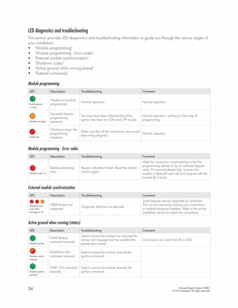
34 Directed Digital System FORD1© 2014 Directed. All rights reserved.
LED diagnostics and troubleshootingThis section provides LED diagnostics and troubleshooting information to guide you through the various stages of your installation.• "Module programming"• "Module programming - Error codes"• "External module synchronization"• "Shutdown codes"• "Active ground while running (status)"• "External commands"
Module programming
LED Description Troubleshooting Comment
Solid greem x 3 sec.
Module successfully programmed. Normal operation. Normal operation.
Flashes orange
Successful bypass programming sequence.
Two keys have been detected (Key2Go, Ignition has been turn ON and OFF twice).
Normal operation, waiting for final step of programming.
Solid red
Waiting to begin theprogramming sequence.
Make sure that all the connections are correct (see wiring diagram) Normal operation.
Module programming - Error codes
LED Description Troubleshooting Comment
Flashes red x 4
Bypass processing error.
Bypass calculation failed. Reset the module and try again.
Might be caused by a bad reading in the first programming attempt or by an unknown bypass value. If a second attempt fails, connect the module to XpressKit and call Tech Support with the module ID in hand.
External module synchronization
LED Description Troubleshooting Comment
(Flashes red, red, then orange) x 10
OBDII feature not supported. Diagnostic data bus not detected.
Some features are not supported by SmartStart. This can be caused by missing wire connections or module hardware limitation. Refer to the wiring installation section to check the connections.
Active ground when running (status)
LED Description Troubleshooting Comment
Flashes green
GWR (Status) command received.
Used to ensure the module has received the remote start message and has enabled the remote start runtime.
Commands can come from RF or D2D
Flashes red & orange
IGNITION ON command received.
Used to ensure the module received the ignition command.
Flashes green quickly
START ON command received.
Used to ensure the module received the ignition command.
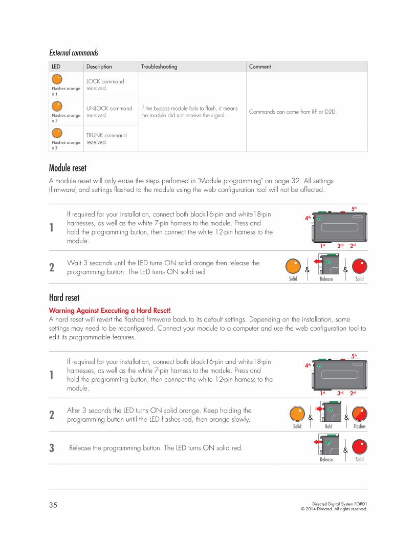
35 Directed Digital System FORD1© 2014 Directed. All rights reserved.
External commands
LED Description Troubleshooting Comment
Flashes orange x 1
LOCK commandreceived.
If the bypass module fails to flash, it means the module did not receive the signal. Commands can come from RF or D2D.
Flashes orange x 2
UNLOCK commandreceived.
Flashes orange x 3
TRUNK commandreceived.
Module resetA module reset will only erase the steps perfomed in "Module programming" on page 32. All settings (firmware) and settings flashed to the module using the web configuration tool will not be affected.
1If required for your installation, connect both black16-pin and white18-pin harnesses, as well as the white 7-pin harness to the module. Press and hold the programming button, then connect the white 12-pin harness to the module.
1st
4th
3rd 2rd
5th
2 Wait 3 seconds until the LED turns ON solid orange then release the programming button. The LED turns ON solid red.
Solid Solid
&&Release
Hard resetWarning Against Executing a Hard Reset! A hard reset will revert the flashed firmware back to its default settings. Depending on the installation, some settings may need to be reconfigured. Connect your module to a computer and use the web configuration tool to edit its programmable features.
1If required for your installation, connect both black16-pin and white18-pin harnesses, as well as the white 7-pin harness to the module. Press and hold the programming button, then connect the white 12-pin harness to the module.
1st
4th
3rd 2rd
5th
2 After 3 seconds the LED turns ON solid orange. Keep holding the programming button until the LED flashes red, then orange slowly.
Hold FlashesSolid
&&
3 Release the programming button. The LED turns ON solid red.
Solid
&Release

36 Directed Digital System FORD1© 2014 Directed. All rights reserved.
Learning the Tach (not needed with Virtual Tach)Tach comes preprogrammed, therefore learning is not required; however, it can be readjusted with the following operations:1. Start the vehicle using the key. 2. Within 5 seconds, press and hold the Control Center* (antenna) or the main module programming button,
until the LED on the Control Center (antenna) or the main module turns ON soild.3. Release the button. Tachometer value is now stored in memory.
If the LED does not turn ON solid, find an alternate tach source.
* If the Control Center (antenna) was not included in your kit, the tach can be programmed using the programming button directly on the main module.
Note: When the tachometer is programmed, the main module automatically enters the Tachometer engine checking mode.
Initializing Virtual Tach (not needed with hardwired or data tach applications)To program Virtual Tach:1. After the install is complete, remote start the engine. The programming operation may require 3 cranks of
the starter before the engine starts and runs. Do not turn off the remote start if this happens, it is a normal programming operation.
2. Once the engine begins running, let it run for at least 30 seconds.3. Using the Remote, send the Remote start command to turn remote start off. Virtual Tach is programmed. To
reset Virtual Tach, a module reset must be done.
Note: Virtual Tach cannot be used in Manual Transmission Mode. It is also not recommended for diesel trucks.
Virtual Tach handles disengaging the starter motor during remote starting – it does not address over-rev. If the customer wants to have the over-rev protection capability, the tach wire or data tach must be used.
Important! After successfully learning Virtual Tach, a small minority of vehicle starters may over crank or under crank during remote start. Use the VirtualTach Fine tune feature in the configuration wizard to adjust the starter output time in 50mS increments to compensate for such an occurrence.

37 Directed Digital System FORD1© 2014 Directed. All rights reserved.
Limited lifetime consumer warrantyDirected Electronics. (“Directed”) promises to the original purchaser to repair or replace (at Directed’s election) with a comparable reconditioned model any Directed unit (hereafter the “unit”), excluding without limitation the siren, the remote transmitters, the associated sensors and accessories, which proves to be defective in workmanship or material under reasonable use during the lifetime of the vehicle provided the following conditions are met: the unit was purchased from an authorized Directed dealer, the unit was professionally installed and serviced by an authorized Directed dealer; the unit will be professionally reinstalled in the vehicle in which it was originally installed by an authorized Directed dealer; and the unit is returned to Directed, shipping prepaid with a legible copy of the bill of sale or other dated proof of purchase bearing the following information: consumer’s name, telephone number and address; the authorized dealers name, telephone number and address; complete product description, including accessories; the year, make and model of the vehicle; vehicle license number and vehicle identification number. All components other than the unit, including without limitation the siren, the remote transmitters and the associated sensors and accessories, carry a one-year warranty from the date of purchase of the same. ALL PRODUCTS RECEIVED BY DIRECTED FOR WARRANTY REPAIR WITHOUT PROOF OF PURCHASE FROM AN AUTHORIZED DEALER WILL BE DENIED. This warranty is non-transferable and is automatically void if: the unit’s date code or serial number is defaced, missing or altered; the unit has been modified or used in a manner contrary to its intended purpose; the unit has been damaged by accident, unreasonable use, neglect, improper service, installation or other causes not arising out of defects in materials or construction. The warranty does not cover damage to the unit caused by installation or removal of the unit. Directed, in its sole discretion, will determine what constitutes excessive damage and may refuse the return of any unit with excessive damage. TO THE MAXIMUM EXTENT ALLOWED BY LAW, ALL WARRANTIES, INCLUDING BUT NOT LIMITED TO EXPRESS WARRANTY, IMPLIED WARRANTY, WARRANTY OF MERCHANTABILITY, FITNESS FOR PARTICULAR PURPOSE AND WARRANTY OF NON-INFRINGEMENT OF INTELLECTUAL PROPERTY, ARE EXPRESSLY EXCLUDED; AND DIRECTED NEITHER ASSUMES NOR AUTHORIZES ANY PERSON OR ENTITY TO ASSUME FOR IT ANY DUTY, OBLIGATION OR LIABILITY IN CONNECTION WITH ITS PRODUCTS. DIRECTED DISCLAIMS AND HAS ABSOLUTELY NO LIABILITY FOR ANY AND ALL ACTS OF THIRD PARTIES INCLUDING ITS AUTHORIZED DEALERS OR INSTALLERS. DIRECTED SECURITY SYSTEMS, INCLUDING THIS UNIT, ARE DETERRENTS AGAINST POSSIBLE THEFT. DIRECTED IS NOT OFFERING A GUARANTEE OR INSURANCE AGAINST VANDALISM, DAMAGE OR THEFT OF THE AUTOMOBILE, ITS PARTS OR CONTENTS; AND HEREBY EXPRESSLY DISCLAIMS ANY LIABILITY WHATSOEVER, INCLUDING WITHOUT LIMITATION, LIABILITY FOR THEFT, DAMAGE AND/OR VANDALISM. THIS WARRANTY DOES NOT COVER LABOR COSTS FOR MAINTENANCE, REMOVAL OR REINSTALLATION OF THE UNIT OR ANY CONSEQUENTIAL DAMAGES OF ANY KIND. IN THE EVENT OF A CLAIM OR A DISPUTE INVOLVING DIRECTED OR ITS SUBSIDIARY, THE VENUE SHALL BE SAN DIEGO COUNTY IN THE STATE OF CALIFORNIA. CALIFORNIA STATE LAWS AND APPLICABLE FEDERAL LAWS SHALL APPLY AND GOVERN THE DISPUTE. THE MAXIMUM RECOVERY UNDER ANY CLAIM AGAINST DIRECTED SHALL BE STRICTLY LIMITED TO THE AUTHORIZED DIRECTED DEALER’S PURCHASE PRICE OF THE UNIT. DIRECTED SHALL NOT BE RESPONSIBLE FOR ANY DAMAGES WHATSOEVER, INCLUDING BUT NOT LIMITED TO, ANY CONSEQUENTIAL DAMAGES, INCIDENTAL DAMAGES, DAMAGE TO VEHICLE, DAMAGES FOR THE LOSS OF TIME, LOSS OF EARNINGS, COMMERCIAL LOSS, LOSS OF ECONOMIC OPPORTUNITY AND THE LIKE. NOTWITHSTANDING THE ABOVE, THE MANUFACTURER DOES OFFER A LIMITED WARRANTY TO REPLACE OR REPAIR THE CONTROL MODULE SUBJECT TO THE CONDITIONS AS DESCRIBED HEREIN. THIS WARRANTY IS VOID IF THE UNIT HAS NOT BEEN PURCHASED FROM DIRECTED, OR AN AUTHORIZED DIRECTED DEALER, OR IF THE UNIT HAS BEEN DAMAGED BY ACCIDENT, UNREASONABLE USE, NEGLIGENCE, ACTS OF GOD, NEGLECT, IMPROPER SERVICE, OR OTHER CAUSES NOT ARISING OUT OF DEFECT IN MATERIALS OR CONSTRUCTION.
Some states do not allow limitations on how long an implied warranty will last or the exclusion or limitation of incidental or consequential damages. This warranty gives you specific legal rights and you may also have other rights that vary from State to State.
This warranty is only valid for sale of product(s) within the United States of America and in Canada. Product(s) sold outside of the United States of America or Canada are sold “AS-IS” and shall have NO WARRANTY, express or implied.
For further details relating to warranty information of Directed products, please visit the support section of Directed’s website at: www.directed.com.
This product may be covered by a Guaranteed Protection Plan (“GPP”). See your authorized Directed dealer for details of the plan or call Directed Customer Service at 1-800-876-0800.
(920-10011-01 2011-06)
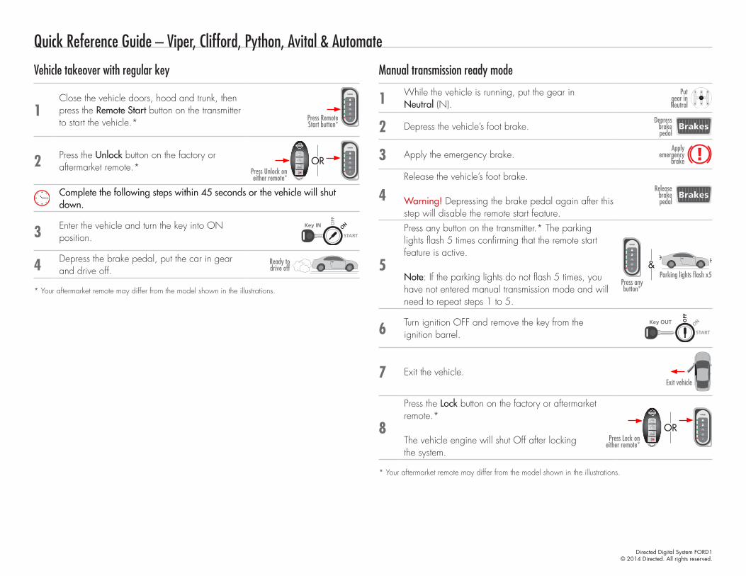
Directed Digital System FORD1© 2014 Directed. All rights reserved.
Quick Reference Guide – Viper, Clifford, Python, Avital & Automate
Vehicle takeover with regular key
1Close the vehicle doors, hood and trunk, then press the Remote Start button on the transmitter to start the vehicle.* Press Remote
Start button*
2 Press the Unlock button on the factory or aftermarket remote.* Press Unlock on
either remote*
OR
Complete the following steps within 45 seconds or the vehicle will shut down.
3 Enter the vehicle and turn the key into ON position. START
Key OUT ONOFF
START
Key IN ONOFF
START
Key IN ONOFF
START
Key IN ONOFF
4 Depress the brake pedal, put the car in gear and drive off.
Ready to drive off
* Your aftermarket remote may differ from the model shown in the illustrations.
Manual transmission ready mode
1 While the vehicle is running, put the gear in Neutral (N).
Put gear in Neutral
2 Depress the vehicle’s foot brake.Depress
brake pedal
3 Apply the emergency brake.Apply
emergency brake
4Release the vehicle’s foot brake.
Warning! Depressing the brake pedal again after this step will disable the remote start feature.
Release brake pedal
5
Press any button on the transmitter.* The parking lights flash 5 times confirming that the remote start feature is active.
Note: If the parking lights do not flash 5 times, you have not entered manual transmission mode and will need to repeat steps 1 to 5.
Parking lights flash x5Press any button*
&
6 Turn ignition OFF and remove the key from the ignition barrel. START
Key OUT ONOFF
START
Key IN ONOFF
START
Key IN ONOFF
START
Key IN ONOFF
7 Exit the vehicle.Exit vehicle
8
Press the Lock button on the factory or aftermarket remote.*
The vehicle engine will shut Off after locking the system.
Press Lock on either remote*
OR
* Your aftermarket remote may differ from the model shown in the illustrations.
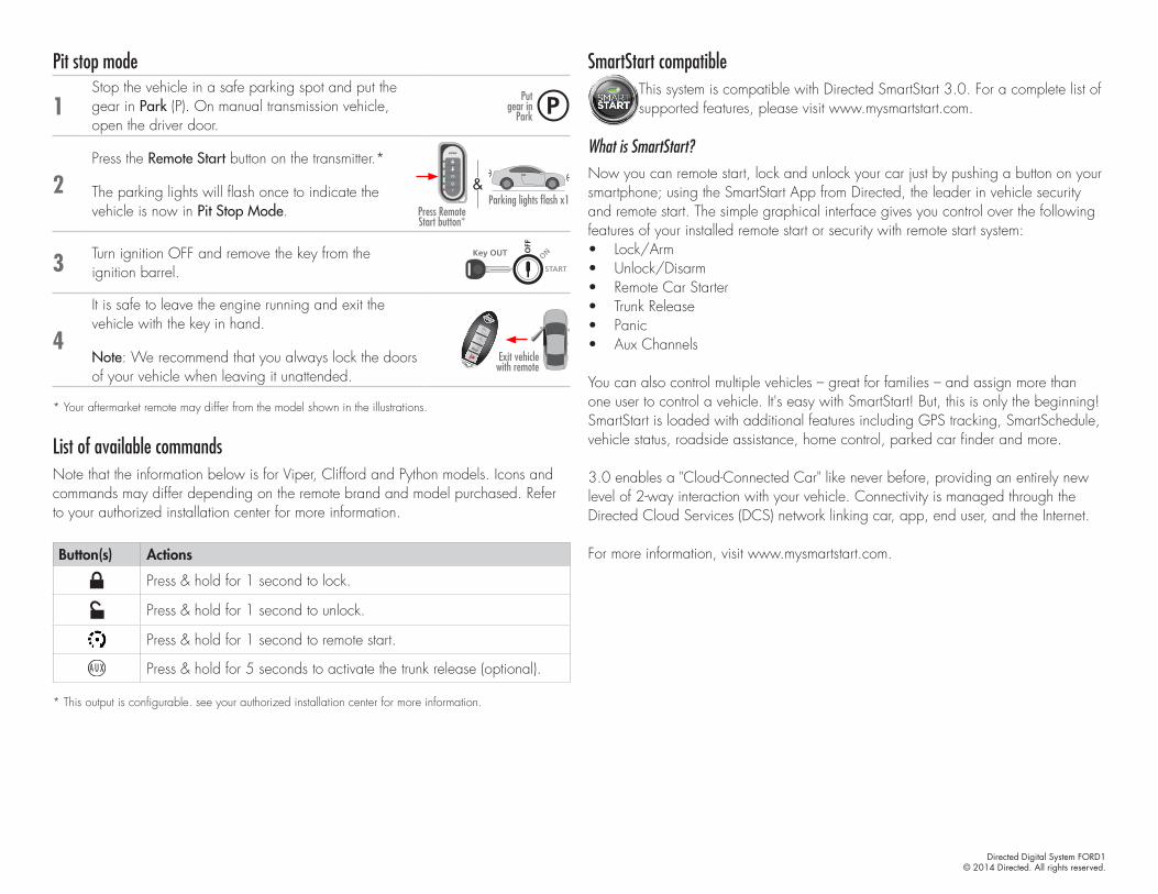
Directed Digital System FORD1© 2014 Directed. All rights reserved.
Pit stop mode
1Stop the vehicle in a safe parking spot and put the gear in Park (P). On manual transmission vehicle, open the driver door.
Put gear in
Park
2Press the Remote Start button on the transmitter.*
The parking lights will flash once to indicate the vehicle is now in Pit Stop Mode.
Parking lights flash x1Press Remote Start button*
&
3 Turn ignition OFF and remove the key from the ignition barrel. START
Key OUT ONOFF
START
Key IN ONOFF
START
Key IN ONOFF
START
Key IN ONOFF
4
It is safe to leave the engine running and exit the vehicle with the key in hand.
Note: We recommend that you always lock the doors of your vehicle when leaving it unattended.
Exit vehicle with remote
* Your aftermarket remote may differ from the model shown in the illustrations.
List of available commandsNote that the information below is for Viper, Clifford and Python models. Icons and commands may differ depending on the remote brand and model purchased. Refer to your authorized installation center for more information.
Button(s) Actions
Press & hold for 1 second to lock.
Press & hold for 1 second to unlock.
Press & hold for 1 second to remote start.
Press & hold for 5 seconds to activate the trunk release (optional).
* This output is configurable. see your authorized installation center for more information.
SmartStart compatibleThis system is compatible with Directed SmartStart 3.0. For a complete list of supported features, please visit www.mysmartstart.com.
What is SmartStart?Now you can remote start, lock and unlock your car just by pushing a button on your smartphone; using the SmartStart App from Directed, the leader in vehicle security and remote start. The simple graphical interface gives you control over the following features of your installed remote start or security with remote start system: • Lock/Arm• Unlock/Disarm• Remote Car Starter• Trunk Release• Panic• Aux Channels
You can also control multiple vehicles – great for families – and assign more than one user to control a vehicle. It's easy with SmartStart! But, this is only the beginning! SmartStart is loaded with additional features including GPS tracking, SmartSchedule, vehicle status, roadside assistance, home control, parked car finder and more.
3.0 enables a "Cloud-Connected Car" like never before, providing an entirely new level of 2-way interaction with your vehicle. Connectivity is managed through the Directed Cloud Services (DCS) network linking car, app, end user, and the Internet.
For more information, visit www.mysmartstart.com.
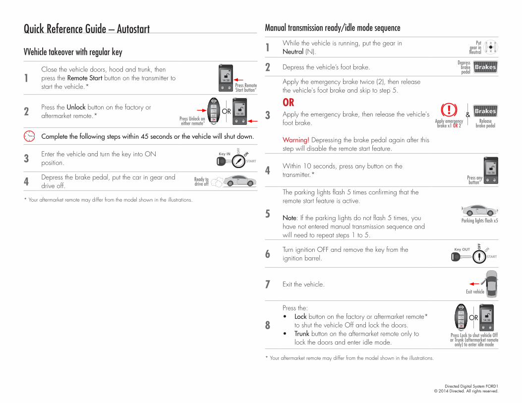
Directed Digital System FORD1© 2014 Directed. All rights reserved.
Quick Reference Guide – Autostart
VVehicle takeover with regular key
1Close the vehicle doors, hood and trunk, then press the Remote Start button on the transmitter to start the vehicle.* Press Remote
Start button*
14:36
2 Press the Unlock button on the factory or aftermarket remote.* Press Unlock on
either remote*
14:36OR
Complete the following steps within 45 seconds or the vehicle will shut down.
3 Enter the vehicle and turn the key into ON position. START
Key OUT ONOFF
START
Key IN ONOFF
START
Key IN ONOFF
START
Key IN ONOFF
4 Depress the brake pedal, put the car in gear and drive off.
Ready to drive off
* Your aftermarket remote may differ from the model shown in the illustrations.
Manual transmission ready/idle mode sequence
1 While the vehicle is running, put the gear in Neutral (N).
Put gear in Neutral
2 Depress the vehicle’s foot brake.Depress
brake pedal
3
Apply the emergency brake twice (2), then release the vehicle's foot brake and skip to step 5.
Apply emergency brake x1 OR 2
Release brake pedal
&
ORApply the emergency brake, then release the vehicle's foot brake.
Warning! Depressing the brake pedal again after this step will disable the remote start feature.
4 Within 10 seconds, press any button on the transmitter.* 14:36
Press any button*
5
The parking lights flash 5 times confirming that the remote start feature is active.
Note: If the parking lights do not flash 5 times, you have not entered manual transmission sequence and will need to repeat steps 1 to 5.
Parking lights flash x5
6 Turn ignition OFF and remove the key from the ignition barrel. START
Key OUT ONOFF
START
Key IN ONOFF
START
Key IN ONOFF
START
Key IN ONOFF
7 Exit the vehicle.Exit vehicle
8
Press the:• Lock button on the factory or aftermarket remote*
to shut the vehicle Off and lock the doors.• Trunk button on the aftermarket remote only to
lock the doors and enter idle mode.Press Lock to shut vehicle Off or Trunk (aftermarket remote
only) to enter idle mode
14:36OR
* Your aftermarket remote may differ from the model shown in the illustrations.
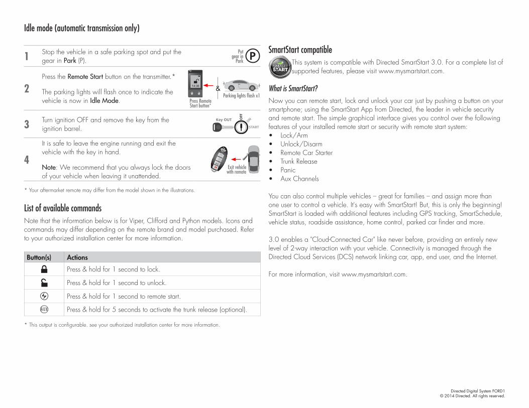
Directed Digital System FORD1© 2014 Directed. All rights reserved.
Idle mode (automatic transmission only)
1 Stop the vehicle in a safe parking spot and put the gear in Park (P).
Put gear in
Park
2Press the Remote Start button on the transmitter.*
The parking lights will flash once to indicate the vehicle is now in Idle Mode.
Parking lights flash x1&
Press Remote Start button*
14:36
3 Turn ignition OFF and remove the key from the ignition barrel. START
Key OUT ONOFF
START
Key IN ONOFF
START
Key IN ONOFF
START
Key IN ONOFF
4
It is safe to leave the engine running and exit the vehicle with the key in hand.
Note: We recommend that you always lock the doors of your vehicle when leaving it unattended.
Exit vehicle with remote
* Your aftermarket remote may differ from the model shown in the illustrations.
List of available commandsNote that the information below is for Viper, Clifford and Python models. Icons and commands may differ depending on the remote brand and model purchased. Refer to your authorized installation center for more information.
Button(s) Actions
Press & hold for 1 second to lock.
Press & hold for 1 second to unlock.
Press & hold for 1 second to remote start.
Press & hold for 5 seconds to activate the trunk release (optional).
* This output is configurable. see your authorized installation center for more information.
SmartStart compatibleThis system is compatible with Directed SmartStart 3.0. For a complete list of supported features, please visit www.mysmartstart.com.
What is SmartStart?Now you can remote start, lock and unlock your car just by pushing a button on your smartphone; using the SmartStart App from Directed, the leader in vehicle security and remote start. The simple graphical interface gives you control over the following features of your installed remote start or security with remote start system: • Lock/Arm• Unlock/Disarm• Remote Car Starter• Trunk Release• Panic• Aux Channels
You can also control multiple vehicles – great for families – and assign more than one user to control a vehicle. It's easy with SmartStart! But, this is only the beginning! SmartStart is loaded with additional features including GPS tracking, SmartSchedule, vehicle status, roadside assistance, home control, parked car finder and more.
3.0 enables a "Cloud-Connected Car" like never before, providing an entirely new level of 2-way interaction with your vehicle. Connectivity is managed through the Directed Cloud Services (DCS) network linking car, app, end user, and the Internet.
For more information, visit www.mysmartstart.com.