forest fire detection by low-cost 13ghz radiometer
TRANSCRIPT

1Universityof Perugia
Forest Fire Detection byLow-Cost 13GHz Radiometer
F. Alimenti, S. Bonafoni, G. Tasselli, S. Leone,L. Roselli, K. Solbach, P. Basili

2Universityof Perugia
Summary
Introduction
Principle of operation
Sensor architecture
Radiometer calibration
Fire experiments
Conclusions

3Universityof Perugia
Microwaves have the inherent capability to penetrate layers of insulating or low-conductivity materials which are non-transparent at optical or infrared frequencies. This property can be exploited to detect fires in forest environment, when they are masked by the vegetation.
To suit this application, the design of a microwave radiometer must address a number of challenging issues. First, it should be possible to manufacture the sensor at low industrial costs. Secondly such a sensor should feature a good radiometric resolution. Third, the reduction of size, weight and power consumption is very important.
This talk addresses the detection of forest fires by microwave radiometers. A low-cost sensor has been developed and fire experiments have been successfully carried-out.
Introduction

4Universityof Perugia
Afoot
TBm
Vegetation
Soil
Atmosphere
Afoot
TBm
Vegetation
Soil
Atmosphere
Principle of operation (model)
Scanning antenna mounted over an observation tower.
Fire up to 1000K.
Soil and vegetation contributions.
Filling factor q defined as the ratio between fire area and antenna footprint area.

5Universityof Perugia
Principle of operation (equations)
Radiometric contrast (ρT) defined as the difference between the brightness temperature in presence of fire with respect to that of the background (soil and vegetation).
In the formula the filling factor is q=Afire/Afoot while physical temperature, emissivity (e) and transmittance (t) are:
fire (TF, eF);
bare soil (TS , eS);
vegetation (TV , eV , tV);
atmosphere (tA).
[ ] qttT)ee(eTeTe=ρ aVVVSFSSFFT ⋅⋅⋅−−−
6Universityof Perugia
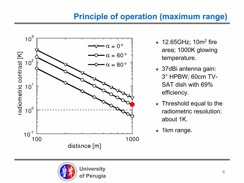
Principle of operation (maximum range)
12.65GHz; 10m2 fire area; 1000K glowing temperature.
37dBi antenna gain: 3° HPBW; 60cm TV-SAT dish with 69% efficiency.
Threshold equal to the radiometric resolution: about 1K.
1km range.

7Universityof Perugia
Principle of operation (effect of vegetation)
Dense Canadian forest: tv=0.4
12.65GHz; 10m2 fire area; 1000K glowing temperature.
Same antenna and same 1K threshold.
0.4km range.

8Universityof Perugia
Sensor architecture (schematic)
Continuous gain calibration by noise adding architecture.
Radiometer offset not corrected (low cost solution).
Calibration circuit: solid-state noise source and 20dB directional coupler.
8051 CPU unit: measurement, calibration, etc.

9Universityof Perugia
Sensor architecture (antenna)
60cm offset dish antenna for TV-SAT applications.
3dB (half-power) beam-width: 3°.
Antenna gain equal to 37dBi.
Antenna efficiency equal to 69%.
Offset angle: 22°.

10Universityof Perugia
Sensor architecture (retrieval equations)
0 10 20 30 401,1
1,2
1,3
1,4
1,5
radi
omet
er o
utpu
t [V
]
time [s]
VON
–VOFF250mV
VON
VOFF
α89.6K
Antenna temperature TAretrieved by noise-adding equations:
βα=TA −⋅ Y
Y=VOFF
VON− VOFF
scale factor 0.36K/mV
ENRC 0 ⋅⋅T=α
0RECT TC+=β ⋅
α and β related to system and receiver parameters.

11Universityof Perugia
Radiometer calibration (waveguide load)
Receiver terminated with a WR75 load.
Load inserted into a climatic chamber.
Temperature swept between 275K and 315K in 5K steps.
Radiometer constants obtained by fitting.
87.4K=α
112.4K=β

12Universityof Perugia
Radiometer calibration (black body)
Receiver connected to a 15dBi standard gain horn antenna.
Antenna pointed toward a black-body (broadband pyramidal absorber) .
Radiometer offset increased by 4K due to antenna mismatch.
116.4K=β

13Universityof Perugia
Fire experiments (laboratory)
Antenna to fire distance 2m; modified TF1 with 21 beechwood sticks; fire side 25cm; 15dBi standard gain horn; HPBW 30°; incidence angle 58°; filling factor 2.7%; estimated fire temperature 1100K; soil temperature 302K; vertical polarization.
25cm
radiometer

14Universityof Perugia
Fire experiments (laboratory)
1 2
3
ρT
=24K
4
Maximum microwave emission associated to embers.

15Universityof Perugia
wooden fire
50cm
Antenna to fire distance 31m; fire diameter 50cm; TV-SAT dish antenna; HPBW 3°; incidence angle 84°; filling factor 0.9%; estimated fire temperature 1100K; soil temperature 298K; horizontal polarization.
Fire experiments (open-space)

16Universityof Perugia
Fire experiments (open-space)
The fire has been clearly detected with radiometric contrast of about 9K.
The point A in the graph is due to the operators crossing the antenna beam.
ρT
=9K

17Universityof Perugia
Fire experiments (obstacle penetration)
Obstacle penetration capabilities studied in indoor environment with walls of concrete material.
Scene sensed with the 15dBi standard gain horn antenna; vertical polarization.
Antenna to fire distance 2.4m; incidence angle 78°; fire side 25cm.

18Universityof Perugia
Fire experiments (obstacle penetration)
ρT
=27K ρT
=17K ρT
=1.4K
no wallfilling factor 3.2%
plasterboard wall112kg/m3
concrete wall2063kg/m3
Microwaves can penetrate obstacles such as wall of buildings that completely mask optical or IR sensors. Obstacle transmissivity is related to bot material conductivity and mass density.
wall thickness 12.5cm

19Universityof Perugia
Conclusions
This work experimentally demonstrates that forest fires with filling factors below 1% can easily be detected by 13GHz radiometers. Obstacles of different nature can also been penetrated.
The maximum microwave emission is related to the embers whereas the flame has never been detected. The mass density of the embers isaround 700kg/m3 and their peak temperature is in excess to 1000K.
System simulations with a 60cm dish antenna, give a maximum range of about 1km without vegetation and of about 400m with vegetation.
A microwave radiometer has customarily been developed for fire detection. It features a component cost of about $1800 and can operate at ambient temperature (I.e. saving the electrical power needed by a thermal control unit ) with a stability of about 2K.

20Universityof Perugia
This research has been funded by the “Fondazione Cassa di Risparmio di Perugia,” in the frame of his support program for the years 2005-2006 and by the “Italian Ministry of University and Research,” with a PRIN project.
The Wireless Solutions WiS S.r.l., a University of Perugia spin-off company, is grateful acknowledged for having made possible the climatic chamber measurements.
The University of Duisburg-Essen (Germany) is acknowledged for having made available its fire detection laboratory.
Prof. Bruno Neri and Dr. Domenico Zito of the University of Pisa (Italy) are acknowledged for having leaded the PRIN project team.
Acknowledgements

21Universityof Perugia
Sensor architecture (receiver)
TV-SAT low-noise block (LNB) used as microwave down-converter.
12.65GHz input in WR75 waveguide.
10.70GHz local oscillator (DRO).
1.95GHz IF with 100MHz noise bandwidth.
8051 CPU unit with 10bit ADC not shown in the figure.
20dBcoupler
inputisolator
IF amplifier andsquare-law detector
referencenoise source
TV-SATdown-converter

22Universityof Perugia
Sensor architecture (custom IF)
Two stages IF amplifier (SGA4486) working at 1.95GHz.
Noise bandwidth determined by a 3-cells ceramic filter.
Schottky diode square-law detector with 7mV/μW sensitivity (narrow-band design).
Fine control of the IF (receiver) gain by digital attenuator.
active biascircuitry
square-lawdetector
2-stageamplifier
1.95GHzfilter
digitalattenuator

23Universityof Perugia
Sensor architecture (measurement cycle)
Integration for τseconds performed numerically by the CPU.
τ set to 1s.
Δt set to 0.1s
Temporal duration of each measurement cycle equal to 2.7s.

24Universityof Perugia
0,01 0,1 1 10 1000,01
0,1
1
experiment theory
ΔT [K
]
τ [s]
Radiometer calibration (sensitivity)
Sensitivity measured as a function of the integration time τ with the radiometer in total power mode.
ΔT=70mK for τ=1s.
Agreement between experiment and theory for Tsys=400K and ΔG/G=1.3x10-4.
21⎟⎠⎞
⎜⎝⎛⋅GΔG+
BτT=ΔT sys

25Universityof Perugia
Climatic chamber results versus time.
Comparison between antenna and physical (WR75 load) temperature.
Maximum error between brightness and physical load temperature ~2K after the transient.
Radiometer calibration (waveguide load)