forest road engineering guidebook - british columbia 2002 province of british columbia citation b.c....
TRANSCRIPT

ofBRITISH COLUMBIA
Forest Road EngineeringGuidebook
Second edition
June 2002
Ministry of Forests


of
BRITISH COLUMBIA
Forest Road EngineeringGuidebook
AuthorityForest Practices Code of British Columbia ActForest Road RegulationOperational Planning Regulation
Second edition
June 2002

© 2002 Province of British Columbia
CitationB.C. Ministry of Forests. 2002. Forest road engineering guidebook.For. Prac. Br., B.C. Min. For., Victoria, B.C. Forest Practices Code of BritishColumbia Guidebook.
http://www.for.gov.bc.ca/tasb/legsregs/fpc/fpcguide/guidetoc.htm
For copies of this or any guidebook, contact:Government PublicationsPO Box 9452, Stn Prov GovtVictoria BC V8W 9V7Telephone: 1-800-663-6105 (outside Victoria)(250) 387-6409 (within Victoria)Fax: (250) 387-1120Internet: http://www.publications.gov.bc.ca
All Guidebooks are available on the British ColumbiaMinistry of Forests home page at:http://www.for.gov.bc.ca/tasb/legsregs/fpc/fpcguide/guidetoc.htm
Forest Road Engineering Guidebook
National Library of Canada Cataloguing in Publication DataMain entry under title:Forest road engineering guidebook. -- 2nd ed.
(Forest practices code of British Columbia)
Previously published: 1995.Includes bibliographical references: p.ISBN 0-7726-4806-9
1. Forest roads - British Columbia - Design and construction. 2. Forest roads - BritishColumbia - Maintenance and repair. 3. Forest roads - Environmental aspects - BritishColumbia. I. British Columbia. Ministry of Forests. II. Series.
SD389.F57 2002 634.9�3�09711 C2002-960150-9

Foreword
This guidebook provides forest road practitioners with advice on road designand field practices to assist them to achieve the statutory and regulatoryrequirements in the Forest Practices Code of British Columbia Act, theForest Road Regulation, and the Operational Planning Regulation.
The practices contained in this document are not mandatory and are not to beinterpreted as the only acceptable options. However, as the Chief Engineerfor the Ministry of Forests, I believe that by using the suggested procedures,a proponent will more likely be successful in addressing his or her legalresponsibilities, at least where the actual site situation matches the conditionscontemplated by the documented practices. The practices described in thedocument have been prepared and reviewed by experts in their field, includ-ing both public and private sector technicians and professionals. Accordingly,I believe this guidebook is a reasonable reflection of acceptable standards ofpractice in the forest sector of British Columbia.
Where a range of options or outcomes apply, such ranges have been given.Where these are not provided, some flexibility may be required in applyingthe guidebook practices, particularly where the proponent believes that suchvariance is warranted based on site-specific conditions.
Ron Davis, P.Eng.Ministry of ForestsChief Engineer - Senior Policy and Standards Engineer
Forest Road Engineering Guidebook
iii

Forest Road Engineering Guidebook
iv

Forest Road Engineering Guidebook
v
Foreword . . . . . . . . . . . . . . . . . . . . . . . . . . . . . . . . . . . . . . . . . . . . . . . . . . . . . . . . . . . . . . . . . iii
Introduction. . . . . . . . . . . . . . . . . . . . . . . . . . . . . . . . . . . . . . . . . . . . . . . . . . . . . . . . . . . . . . . . 1
1. Road Layout and Design . . . . . . . . . . . . . . . . . . . . . . . . . . . . . . . . . . . . . . . . . . . . . . . . . . . 3Introduction. . . . . . . . . . . . . . . . . . . . . . . . . . . . . . . . . . . . . . . . . . . . . . . . . . . . . . . . . . . . . 3District manager approval of road layout and design . . . . . . . . . . . . . . . . . . . . . . . . . . . . 3Route selection and layout . . . . . . . . . . . . . . . . . . . . . . . . . . . . . . . . . . . . . . . . . . . . . . . . . 4Survey level selection . . . . . . . . . . . . . . . . . . . . . . . . . . . . . . . . . . . . . . . . . . . . . . . . . . . . . 6Procedures for field traverses and location surveys . . . . . . . . . . . . . . . . . . . . . . . . . . . . . . 8Road design requirements. . . . . . . . . . . . . . . . . . . . . . . . . . . . . . . . . . . . . . . . . . . . . . . . . 12Correction factors to adjust for swell and shrinkage of materials . . . . . . . . . . . . . . . . . . 17Slope stability considerations . . . . . . . . . . . . . . . . . . . . . . . . . . . . . . . . . . . . . . . . . . . . . . 20Design specifications and parameters. . . . . . . . . . . . . . . . . . . . . . . . . . . . . . . . . . . . . . . . 25Suggestions for further reading . . . . . . . . . . . . . . . . . . . . . . . . . . . . . . . . . . . . . . . . . . . . 34
2. Design and Construction of Bridges and Stream Culverts . . . . . . . . . . . . . . . . . . . . . . 37Introduction. . . . . . . . . . . . . . . . . . . . . . . . . . . . . . . . . . . . . . . . . . . . . . . . . . . . . . . . . . . . 37Design requirements for bridges and stream culverts . . . . . . . . . . . . . . . . . . . . . . . . . . . 38Bridge and major culvert design responsibility . . . . . . . . . . . . . . . . . . . . . . . . . . . . . . . . 38Site data and survey requirements for bridges and major culverts . . . . . . . . . . . . . . . . . 41Construction drawings and specifications . . . . . . . . . . . . . . . . . . . . . . . . . . . . . . . . . . . . 42Culverts on non�fish-bearing streams . . . . . . . . . . . . . . . . . . . . . . . . . . . . . . . . . . . . . . . 48Estimating design discharge for streams . . . . . . . . . . . . . . . . . . . . . . . . . . . . . . . . . . . . . 49Some methodologies to estimate design flood discharge. . . . . . . . . . . . . . . . . . . . . . . . . 50General conformance and construction documentation . . . . . . . . . . . . . . . . . . . . . . . . . . 53Suggestions for further reading . . . . . . . . . . . . . . . . . . . . . . . . . . . . . . . . . . . . . . . . . . . . 55
3. Road Construction . . . . . . . . . . . . . . . . . . . . . . . . . . . . . . . . . . . . . . . . . . . . . . . . . . . . . . . 57Introduction. . . . . . . . . . . . . . . . . . . . . . . . . . . . . . . . . . . . . . . . . . . . . . . . . . . . . . . . . . . . 57Road corridor preparation. . . . . . . . . . . . . . . . . . . . . . . . . . . . . . . . . . . . . . . . . . . . . . . . . 58Grubbing and stripping . . . . . . . . . . . . . . . . . . . . . . . . . . . . . . . . . . . . . . . . . . . . . . . . . . . 63Disposal of slash and debris . . . . . . . . . . . . . . . . . . . . . . . . . . . . . . . . . . . . . . . . . . . . . . . 64Subgrade construction. . . . . . . . . . . . . . . . . . . . . . . . . . . . . . . . . . . . . . . . . . . . . . . . . . . . 72Stabilizing the subgrade and surfacing the road. . . . . . . . . . . . . . . . . . . . . . . . . . . . . . . . 85Construction and use of snow and one-season winter roads . . . . . . . . . . . . . . . . . . . . . . 87Construction of 5-year roads . . . . . . . . . . . . . . . . . . . . . . . . . . . . . . . . . . . . . . . . . . . . . . 90Surface erosion and sediment control. . . . . . . . . . . . . . . . . . . . . . . . . . . . . . . . . . . . . . . . 91Road works shutdown indicators and procedures . . . . . . . . . . . . . . . . . . . . . . . . . . . . . . 93Suggestions for further reading . . . . . . . . . . . . . . . . . . . . . . . . . . . . . . . . . . . . . . . . . . . . 94
4. Road Drainage Construction . . . . . . . . . . . . . . . . . . . . . . . . . . . . . . . . . . . . . . . . . . . . . . . 97Introduction. . . . . . . . . . . . . . . . . . . . . . . . . . . . . . . . . . . . . . . . . . . . . . . . . . . . . . . . . . . . 97Maintaining surface drainage patterns . . . . . . . . . . . . . . . . . . . . . . . . . . . . . . . . . . . . . . . 97Temporary stream crossings . . . . . . . . . . . . . . . . . . . . . . . . . . . . . . . . . . . . . . . . . . . . . . . 99Ditch construction considerations. . . . . . . . . . . . . . . . . . . . . . . . . . . . . . . . . . . . . . . . . . 100
Contents

Forest Road Engineering Guidebook
vi
Cross-drain culvert location . . . . . . . . . . . . . . . . . . . . . . . . . . . . . . . . . . . . . . . . . . . . . . 104Cross-drain culvert installation. . . . . . . . . . . . . . . . . . . . . . . . . . . . . . . . . . . . . . . . . . . . 105Backfilling and compaction around pipe culverts . . . . . . . . . . . . . . . . . . . . . . . . . . . . . 105Log culvert design . . . . . . . . . . . . . . . . . . . . . . . . . . . . . . . . . . . . . . . . . . . . . . . . . . . . . 106Log culvert construction . . . . . . . . . . . . . . . . . . . . . . . . . . . . . . . . . . . . . . . . . . . . . . . . . 113Ford design and construction on non-fish streams . . . . . . . . . . . . . . . . . . . . . . . . . . . . . 114Suggestions for further reading . . . . . . . . . . . . . . . . . . . . . . . . . . . . . . . . . . . . . . . . . . . 119
5. Road and Structure Inspection and Maintenance. . . . . . . . . . . . . . . . . . . . . . . . . . . . . 121Introduction. . . . . . . . . . . . . . . . . . . . . . . . . . . . . . . . . . . . . . . . . . . . . . . . . . . . . . . . . . . 121Assigning road inspection priorities . . . . . . . . . . . . . . . . . . . . . . . . . . . . . . . . . . . . . . . . 121Road inspections . . . . . . . . . . . . . . . . . . . . . . . . . . . . . . . . . . . . . . . . . . . . . . . . . . . . . . . 123Bridge and major culvert inspections . . . . . . . . . . . . . . . . . . . . . . . . . . . . . . . . . . . . . . . 125Road prism maintenance. . . . . . . . . . . . . . . . . . . . . . . . . . . . . . . . . . . . . . . . . . . . . . . . . 126Subgrade maintenance . . . . . . . . . . . . . . . . . . . . . . . . . . . . . . . . . . . . . . . . . . . . . . . . . . 127Clearing width maintenance . . . . . . . . . . . . . . . . . . . . . . . . . . . . . . . . . . . . . . . . . . . . . . 127Ditch and culvert maintenance . . . . . . . . . . . . . . . . . . . . . . . . . . . . . . . . . . . . . . . . . . . . 127Road surface maintenance . . . . . . . . . . . . . . . . . . . . . . . . . . . . . . . . . . . . . . . . . . . . . . . 128Structure maintenance. . . . . . . . . . . . . . . . . . . . . . . . . . . . . . . . . . . . . . . . . . . . . . . . . . . 129Inspection and repair of temporary and semi-permanently deactivated roads. . . . . . . . 131Suggestions for further reading . . . . . . . . . . . . . . . . . . . . . . . . . . . . . . . . . . . . . . . . . . . 131
6. Road Deactivation. . . . . . . . . . . . . . . . . . . . . . . . . . . . . . . . . . . . . . . . . . . . . . . . . . . . . . . 133Introduction. . . . . . . . . . . . . . . . . . . . . . . . . . . . . . . . . . . . . . . . . . . . . . . . . . . . . . . . . . . 133Objectives of deactivation . . . . . . . . . . . . . . . . . . . . . . . . . . . . . . . . . . . . . . . . . . . . . . . 133Deactivation levels . . . . . . . . . . . . . . . . . . . . . . . . . . . . . . . . . . . . . . . . . . . . . . . . . . . . . 134Water management techniques . . . . . . . . . . . . . . . . . . . . . . . . . . . . . . . . . . . . . . . . . . . . 136Road fill pullback . . . . . . . . . . . . . . . . . . . . . . . . . . . . . . . . . . . . . . . . . . . . . . . . . . . . . . 147Typical applications of deactivation techniques. . . . . . . . . . . . . . . . . . . . . . . . . . . . . . . 149Methodology to develop deactivation prescriptions. . . . . . . . . . . . . . . . . . . . . . . . . . . . 150Involvement of professionals in road deactivation. . . . . . . . . . . . . . . . . . . . . . . . . . . . . 154Revegetation requirements for deactivated roads. . . . . . . . . . . . . . . . . . . . . . . . . . . . . . 156Deactivation hazard warning signs. . . . . . . . . . . . . . . . . . . . . . . . . . . . . . . . . . . . . . . . . 158Post-deactivation inspections and maintenance . . . . . . . . . . . . . . . . . . . . . . . . . . . . . . . 158Acceptance of permanent deactivation. . . . . . . . . . . . . . . . . . . . . . . . . . . . . . . . . . . . . . 158Suggestions for further reading . . . . . . . . . . . . . . . . . . . . . . . . . . . . . . . . . . . . . . . . . . . 158
1. Field identification of soils . . . . . . . . . . . . . . . . . . . . . . . . . . . . . . . . . . . . . . . . . . . . . . . 161
2. Vertical (parabolic) curves. . . . . . . . . . . . . . . . . . . . . . . . . . . . . . . . . . . . . . . . . . . . . . . . 165
3. Plotting data: plan and profile information . . . . . . . . . . . . . . . . . . . . . . . . . . . . . . . . . . . 171
4. Statement of construction conformance . . . . . . . . . . . . . . . . . . . . . . . . . . . . . . . . . . . . . 177
5. Tables to establish clearing width . . . . . . . . . . . . . . . . . . . . . . . . . . . . . . . . . . . . . . . . . . 179
6. Sample road inspection and maintenance report. . . . . . . . . . . . . . . . . . . . . . . . . . . . . . . 187
7. Sample road deactivation inspection report . . . . . . . . . . . . . . . . . . . . . . . . . . . . . . . . . . 191
8. Example field data form for deactivation field assessments. . . . . . . . . . . . . . . . . . . . . . 193
9. Example road deactivation prescription content requirements . . . . . . . . . . . . . . . . . . . . 195
10. Landslide risk analysis . . . . . . . . . . . . . . . . . . . . . . . . . . . . . . . . . . . . . . . . . . . . . . . . . . 197
Forest Road Engineering Guidebook
vii
Figures
Appendices
1. Typical benchmarks and reference. . . . . . . . . . . . . . . . . . . . . . . . . . . . . . . . . . . . . . . . . . . 12
2. Typical roadway on moderate slopes with no additional clearing.. . . . . . . . . . . . . . . . . . 15
3. Example of material volume variation with time for various stages of road construction. . . . . . . . . . . . . . . . . . . . . . . . . . . . . . . . . . . . . . . . . . . . . . . . . . . . . . . . 18
4. Sample of general arrangement and layout (simple creek crossing). . . . . . . . . . . . . . . . . 44
5. Sample of general arrangement and layout (complex creek crossing). . . . . . . . . . . . . . . 45
6. High water width cross-sectional area. . . . . . . . . . . . . . . . . . . . . . . . . . . . . . . . . . . . . . . . 53
7. Typical roadway on gentle slopes with no additional clearing. . . . . . . . . . . . . . . . . . . . . 59
8. Typical permanent roadway on moderate slopes (best practice). . . . . . . . . . . . . . . . . . . . 60
9. Permanent road in low likelihood of landslide terrain (acceptable practice). . . . . . . . . . 65
10. Typical 5-year road showing debris placement. . . . . . . . . . . . . . . . . . . . . . . . . . . . . . . . . 66
11. Slash and debris disposal by piling and burning. . . . . . . . . . . . . . . . . . . . . . . . . . . . . . . . 67
12. Slash and debris disposal by burying. . . . . . . . . . . . . . . . . . . . . . . . . . . . . . . . . . . . . . . . . 68
13. Slash and debris disposal by trenching. . . . . . . . . . . . . . . . . . . . . . . . . . . . . . . . . . . . . . . 69
14. Slash and debris disposal by scattering. . . . . . . . . . . . . . . . . . . . . . . . . . . . . . . . . . . . . . . 71
15. Overlanding cross-section with corduroy.. . . . . . . . . . . . . . . . . . . . . . . . . . . . . . . . . . . . . 82
16. Overlanding cross-section with inverted stumps. . . . . . . . . . . . . . . . . . . . . . . . . . . . . . . . 82
17. Typical snow road. . . . . . . . . . . . . . . . . . . . . . . . . . . . . . . . . . . . . . . . . . . . . . . . . . . . . . . 88
18. One-season winter road. . . . . . . . . . . . . . . . . . . . . . . . . . . . . . . . . . . . . . . . . . . . . . . . . . . 89
19. Simple log culvert. . . . . . . . . . . . . . . . . . . . . . . . . . . . . . . . . . . . . . . . . . . . . . . . . . . . . . 106
20. Fill containment for log culvert. . . . . . . . . . . . . . . . . . . . . . . . . . . . . . . . . . . . . . . . . . . . 109
21. Plan and profile of a ford crossing. . . . . . . . . . . . . . . . . . . . . . . . . . . . . . . . . . . . . . . . . . 118
22. Cross-ditch installation across an intact road.. . . . . . . . . . . . . . . . . . . . . . . . . . . . . . . . . 137
23. Cross-ditch installation across full road pullback. . . . . . . . . . . . . . . . . . . . . . . . . . . . . . 138
1. Example correction factors to convert compacted volume to bank volume for various materials. . . . . . . . . . . . . . . . . . . . . . . . . . . . . . . . . . . . . . . . . . . . . . . . . . . . . . 19
2. Summary of alignment controls for forest roads. . . . . . . . . . . . . . . . . . . . . . . . . . . . . . . . 27
3. Minimum subgrade widths for roads on curves, for pole and tri-axle trailer configurations, and for lowbed vehicles. . . . . . . . . . . . . . . . . . . . . . . . . . . . . . . . . . . . . . 28
4. Recommended turnout widths, based on stabilized road widths. . . . . . . . . . . . . . . . . . . . 28
5. General guidelines for cut and fill slope angles for use in forest road design. . . . . . . . . 31
6. Round pipe culvert area (Ac ) versus pipe diameter. . . . . . . . . . . . . . . . . . . . . . . . . . . . . 53
7. Example erosion velocities.. . . . . . . . . . . . . . . . . . . . . . . . . . . . . . . . . . . . . . . . . . . . . . . . 84
8. Log culvert stringer sizing table�log diameters are mid-diameters, in millimetres. . . 111
Forest Road Engineering Guidebook
viii
Tables
24. Waterbar installation.. . . . . . . . . . . . . . . . . . . . . . . . . . . . . . . . . . . . . . . . . . . . . . . . . . . . 139
25. Metal or plastic pipe stream culvert removal (non-fish stream). . . . . . . . . . . . . . . . . . . 140
26. Log stream culvert removal (non-fish stream).. . . . . . . . . . . . . . . . . . . . . . . . . . . . . . . . 141
27. Trench drain. . . . . . . . . . . . . . . . . . . . . . . . . . . . . . . . . . . . . . . . . . . . . . . . . . . . . . . . . . . 141
28. Blanket drain. . . . . . . . . . . . . . . . . . . . . . . . . . . . . . . . . . . . . . . . . . . . . . . . . . . . . . . . . . 142
29. French drain. . . . . . . . . . . . . . . . . . . . . . . . . . . . . . . . . . . . . . . . . . . . . . . . . . . . . . . . . . . 143
30. Example of a ford installed on a non�fish-bearing stream. . . . . . . . . . . . . . . . . . . . . . . 144
31. Example of an armoured swale. . . . . . . . . . . . . . . . . . . . . . . . . . . . . . . . . . . . . . . . . . . . 145
32. Insloping and outsloping the road surface. . . . . . . . . . . . . . . . . . . . . . . . . . . . . . . . . . . . 146
33. Grader windrow and spoil pile berm (site conditions before fill pullback).. . . . . . . . . . 146
34. Example of full road fill pullback. . . . . . . . . . . . . . . . . . . . . . . . . . . . . . . . . . . . . . . . . . 148
35. Partial road fill pullback. . . . . . . . . . . . . . . . . . . . . . . . . . . . . . . . . . . . . . . . . . . . . . . . . . 148
Introduction
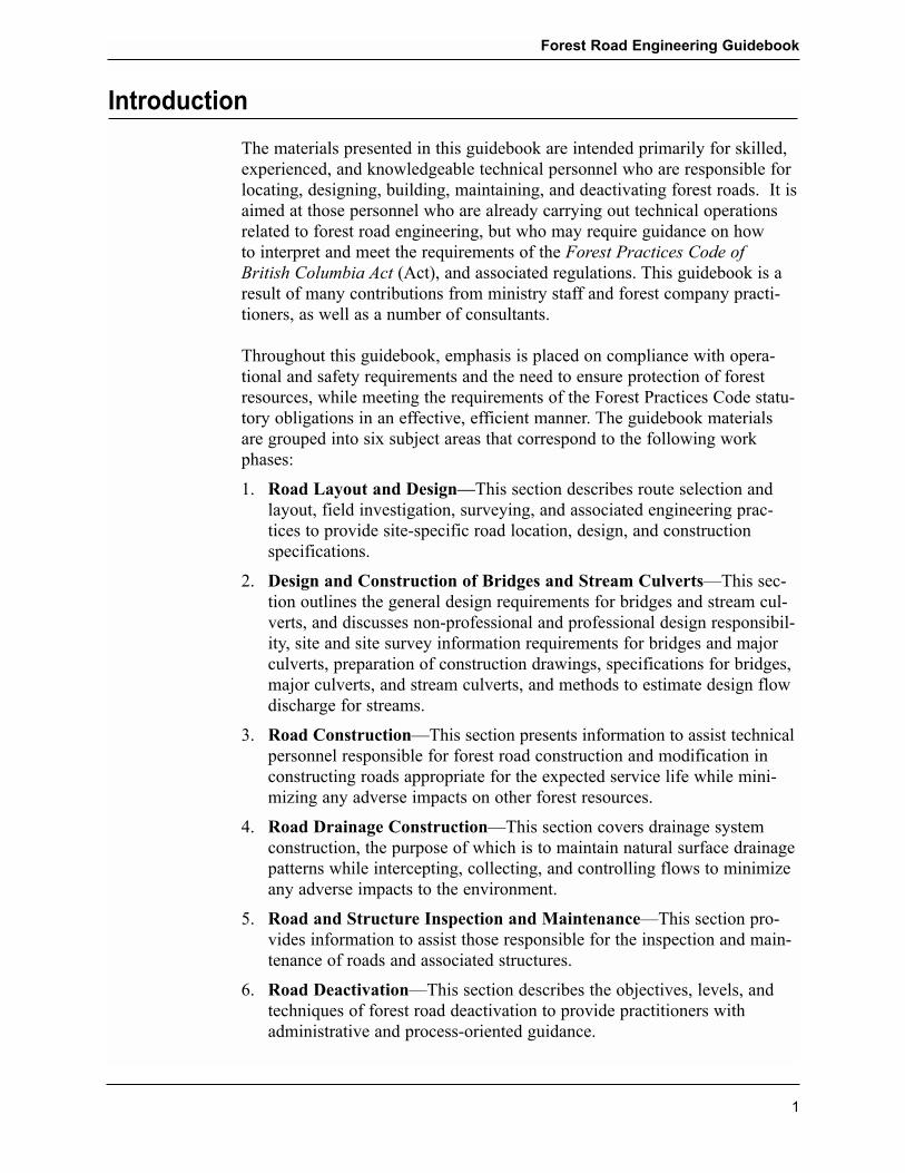
The materials presented in this guidebook are intended primarily for skilled,experienced, and knowledgeable technical personnel who are responsible forlocating, designing, building, maintaining, and deactivating forest roads. It isaimed at those personnel who are already carrying out technical operationsrelated to forest road engineering, but who may require guidance on how to interpret and meet the requirements of the Forest Practices Code of British Columbia Act (Act), and associated regulations. This guidebook is aresult of many contributions from ministry staff and forest company practi-tioners, as well as a number of consultants.
Throughout this guidebook, emphasis is placed on compliance with opera-tional and safety requirements and the need to ensure protection of forestresources, while meeting the requirements of the Forest Practices Code statu-tory obligations in an effective, efficient manner. The guidebook materialsare grouped into six subject areas that correspond to the following workphases:
1. Road Layout and Design�This section describes route selection andlayout, field investigation, surveying, and associated engineering prac-tices to provide site-specific road location, design, and construction specifications.
2. Design and Construction of Bridges and Stream Culverts�This sec-tion outlines the general design requirements for bridges and stream cul-verts, and discusses non-professional and professional design responsibil-ity, site and site survey information requirements for bridges and majorculverts, preparation of construction drawings, specifications for bridges,major culverts, and stream culverts, and methods to estimate design flowdischarge for streams.
3. Road Construction�This section presents information to assist technicalpersonnel responsible for forest road construction and modification inconstructing roads appropriate for the expected service life while mini-mizing any adverse impacts on other forest resources.
4. Road Drainage Construction�This section covers drainage systemconstruction, the purpose of which is to maintain natural surface drainagepatterns while intercepting, collecting, and controlling flows to minimizeany adverse impacts to the environment.
5. Road and Structure Inspection and Maintenance�This section pro-vides information to assist those responsible for the inspection and main-tenance of roads and associated structures.
6. Road Deactivation�This section describes the objectives, levels, andtechniques of forest road deactivation to provide practitioners withadministrative and process-oriented guidance.
Forest Road Engineering Guidebook
1

Forest Road Engineering Guidebook
2

1. Road Layout and Design
Introduction
Forest road layout and design is a process that includes route selection, fieldinvestigation, surveying, and analysis to provide a site-specific road locationand design. Road design provides construction specifications, road prismgeometry, stream crossing site information, and information necessary forconstruction control.
The detail and information required for each phase in this process varies withthe type of road required, the complexity of terrain, the size and complexityof stream crossings, and other resource values.
This chapter:
� describes the types of projects for which the district manager�s approvalof road layout and design for construction and modification is mandatory
� provides information on route selection and layout, and describes thecontent requirements of a reconnaissance report
� provides criteria for survey level selection, and explains the types of sur-vey (field traverse and location survey), and the suitability and applica-tion of different survey levels
� provides procedures for field traverses and location surveys
� explains general and geometric road design requirements
� provides example correction factors to convert compacted volume tobank volume for road design purposes
� discusses slope stability considerations if a proposed road will cross areaswith a moderate or high likelihood of landslides
� provides road design specifications and parameters.
District manager approval of road layout and design
The Ministry of Forests has developed a package of road layout and designforms and administrative procedures that incorporate the statutory contentsfor road layout and design. This information can be found at an appropriateMinistry of Forests website.
The district manager approves road construction and modification for forestroads under various permits. In general, unless the district manager requiresit, the following types of projects are exempted from needing his or herapproval of road layout and design:
Forest Road Engineering Guidebook
3
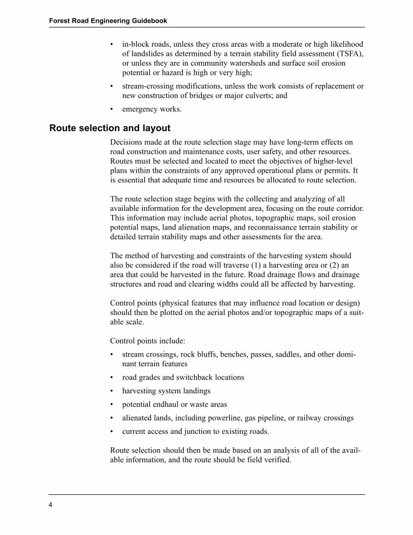
� in-block roads, unless they cross areas with a moderate or high likelihoodof landslides as determined by a terrain stability field assessment (TSFA),or unless they are in community watersheds and surface soil erosionpotential or hazard is high or very high;
� stream-crossing modifications, unless the work consists of replacement ornew construction of bridges or major culverts; and
� emergency works.
Route selection and layout
Decisions made at the route selection stage may have long-term effects onroad construction and maintenance costs, user safety, and other resources.Routes must be selected and located to meet the objectives of higher-levelplans within the constraints of any approved operational plans or permits. Itis essential that adequate time and resources be allocated to route selection.
The route selection stage begins with the collecting and analyzing of allavailable information for the development area, focusing on the route corridor.This information may include aerial photos, topographic maps, soil erosionpotential maps, land alienation maps, and reconnaissance terrain stability ordetailed terrain stability maps and other assessments for the area.
The method of harvesting and constraints of the harvesting system shouldalso be considered if the road will traverse (1) a harvesting area or (2) anarea that could be harvested in the future. Road drainage flows and drainagestructures and road and clearing widths could all be affected by harvesting.
Control points (physical features that may influence road location or design)should then be plotted on the aerial photos and/or topographic maps of a suit-able scale.
Control points include:
� stream crossings, rock bluffs, benches, passes, saddles, and other domi-nant terrain features
� road grades and switchback locations
� harvesting system landings
� potential endhaul or waste areas
� alienated lands, including powerline, gas pipeline, or railway crossings
� current access and junction to existing roads.
Route selection should then be made based on an analysis of all of the avail-able information, and the route should be field verified.
Forest Road Engineering Guidebook
4

The route selection field phase is an on-the-ground check of the proposedroute or potential routes, taking into consideration control points or otherconstraints. This field traverse is also known as a Level 1 survey (measure-ments are not usually accurate enough for detailed road design) and is runalong a proposed route to confirm that the horizontal and vertical alignmentare suitable. Adjustments to the line may be necessary, and often several iter-ations are needed to establish the alignment and confirm the choice of route.
The person carrying out the field traverse should make sufficient notes toprepare a detailed reconnaissance report to assist the location surveyors, roaddesigners, and road builders.
The reconnaissance report should identify and or confirm:
� terrain conditions and road sections that are in unstable or potentiallyunstable terrain
� road sections with side slopes over 60% or where slope instability isfound
� control points and topographic features (e.g., rock bluffs, swamps, ava-lanche paths, landslides, and debris slides), including those that may beused as photo ties
� the sections of road that encroach on public utilities
� the sections of road that are adjacent to or cross private property, Crownleases, or mineral and placer claims or leases (where possible, alienatedlands should be avoided)
� all continuous and intermittent drainage flow channels, springs, seeps,and wet areas
� riparian areas
� stream crossings where channel and bank disturbances can be preventedor mitigated, locations that require site plans, and data required for minorstream crossings
� forest cover (species composition, timber quality, and volume perhectare)
� recommended slash and debris disposal methods and additional clearingwidths required for the slash and debris disposal
� soil types based on visual observations of exposed cuts, shallow hand-dug test holes and probing, and the location of these soils on maps or aer-ial photos (see Appendix 1 for a method of identifying soils)
� maximum road grades and minimum curve radii
� location and extent of bedrock, if rippable, and the potential as ballast
� location and extent of gravel sources and the potential for use as sub-grade and surfacing materials
Forest Road Engineering Guidebook
5

� endhaul sections and potential waste areas
� recommended construction methods and potentially appropriate alterna-tives
� recommended survey level or levels appropriate for the terrain.
The field reconnaissance report should also record the characteristics ofexisting roads in the vicinity of the proposed road location by identifying andrecording soil types, stable cut and fill slope angles, and existing sources ofroad surfacing materials.
Field reconnaissance is an appropriate stage to evaluate the need for anyadditional information or assessments that may include:
� TSFAs
� riparian classification of streams, wetlands, and lakes
� identification of fish streams in community watersheds
� visual impact assessments
� archaeological impact assessments
� soil erosion field assessments.
Survey level selection
There are two general types of surveys: a field traverse and a location survey.There are also four levels of survey intensity: Survey Levels 1, 2, 3, and 4.These survey types and levels are briefly explained below.
To determine which survey type and level to recommend in the reconnais-sance report, the physical characteristics of the terrain, design complexity,and desired road prism geometry should be considered.
Types of survey
Field traverse
A field traverse is required for road layout and design and is conducted tocollect data and measurements for the road location. A field traverse is alsosometimes referred to as Survey Level 1 (see �Survey levels� below).
Location survey
A location survey is carried out to obtain information and measurements necessary for detailed design, or to obtain information when geometric roaddesigns are required. Compared to a field traverse, a location survey is carriedout at a higher level of survey intensity (i.e., Survey Level 2, 3, or 4).
Forest Road Engineering Guidebook
6

If as-built surveys are required for volume determination or to check confor-mance to the design, the location survey level should be suitable for accu-rately re-establishing the road centreline location.
If construction surveys are required, the location survey level should be suit-able to accurately re-establish the construction control points.
The accuracy achieved with any survey level depends, in part, on the typeand condition of survey equipment used, the competence of the crew, and thefield methods used. Global Positioning System (GPS) receivers, like othersurvey equipment, are acceptable when they can achieve the required hori-zontal and vertical accuracy for the appropriate survey level.
Stream crossings require special consideration. Site information requirementsfor bridge and culvert planning and design are provided later in this chapter.
Winter-constructed roads require special layout considerations to identify thelocation of cross-drains and stream crossings. Long continuous grades shouldbe avoided, since they easily become conduits for meltwater and groundwaterseepage. Steep cut banks should be avoided because they may slough or fail,blocking ditches and sending ditchwater onto the road surface and creatingthe potential for major surface erosion.
Survey levels
The following criteria are used to determine the appropriate survey level fora field traverse (Survey Level 1) or location survey (Survey Levels 2, 3, or 4).
Survey Level 1 (for field traverses)
Application: For field traverses on stable terrain with a low likelihood oflandslides and where geometric road design, construction surveys, and as-built surveys are not required. The necessary accuracy of survey may beachieved with basic field equipment such as hand compass, clinometer, andhip chain.
Horizontal accuracy: Turning points are established to a relative accuracy of 1:100.
Vertical accuracy: Not applicable.
Survey Level 2 (for location surveys on stable terrain)
Application: For location surveys on stable terrain with a low likelihood oflandslides and where a geometric road design, construction surveys, or as-built surveys are desired.
Forest Road Engineering Guidebook
7

Horizontal accuracy: Turning points to be established to a relative accuracyof 1:300.
Vertical accuracy: = , expressedin metres. For example, the vertical accuracy for a 1-km road is 1 m. For a 2-km road, the vertical accuracy is 1.41 m.
Survey Level 3 (for location surveys within areas of moderate or high likelihood of landslides)
Application: For location surveys, construction surveys, geometric roaddesign, and as-built surveys in areas of moderate to high likelihood of land-slides as determined by a TSFA. Appropriate level of survey for material volume determination and detailed-engineered estimates. This level of surveymay also be used for bridge and major culvert planning and design, butgreater vertical accuracy would possibly be necessary.
Horizontal accuracy: Turning points to be established to a relative accuracyof 1:1000.
Vertical accuracy: = 0.5 × ,expressed in metres. For example, the vertical accuracy for a 1-km road is0.5 m. For a 2-km road, the vertical accuracy is 0.71 m.
Survey Level 4 (for high-order survey requirements)
Application: A high-order survey for location surveys, construction surveys,construction contracting on a cost-per-unit basis, check surveys, placement ofpermanent bridges, as-built surveys through Crown leases, mineral and placerclaims, and leases, private property, and surveys to re-establish private prop-erty lines.
Horizontal accuracy: Turning hubs are to be established to a relative accura-cy of 1:5000.
Vertical accuracy: = 0.3 × ,expressed in metres. For example, the vertical accuracy for a 1-km road is0.3 m. For a 2-km road, the vertical accuracy is 0.42 m.
Procedures for field traverses and location surveys
This section outlines the minimum requirements for field traverses and loca-tion surveys. Although considerable gains have been made in survey instru-mentation technology, use of the technology does not preclude the need tofollow standard survey practices. Standard practices are outlined in theManual for Roads and Transportation (BCIT 1984).
√ total horizontal distance measured in kilometres
√ total horizontal distance measured in kilometres
√ total horizontal distance measured in kilometres
Forest Road Engineering Guidebook
8
Survey Level 1 (for field traverses)
Where no location survey is required (e.g., where a proposed road will notcross areas with a moderate or high likelihood of landslides as determined bya TSFA):
1. Clearly identify the beginning and end of the road.
2. Clearly flag the proposed centreline of the road.
3. Using an appropriate method (such as aluminum plaques and tree blazes),mark and record control points, noting the control point number, station,bearing, and horizontal distance from the proposed centreline.
4. Record notes on forest cover, vegetative types, soil types, rock, groundwater seepage, streams, etc.
Survey Levels 2 and 3 (for location surveys)
Traverse
1. Clearly identify the beginning and end of the road.
2. Establish intervisible stations called turning points (TPs) if using a com-pass or traverse hubs if using a transit�along the preliminary centreline(P-Line). Use manufactured stakes or local material (blazing of saplings)driven into the ground.
3. Measure the bearing, slope gradient, and distance between TPs and markthe cumulative chainages and/or point number in the field.
4. Measure the slope gradient and distance to additional grade breaksbetween TPs as intermediate fore shots to facilitate taking cross-sectionsat those locations.
5. Using an appropriate method (such as aluminum plaques and tree blazes),mark and record control points, reference points and bench marks, notingthe number, station, bearing, and horizontal distance from the P-Line.
6. Record notes on forest cover, vegetative types, soil types, rock, groundwater seepage, streams, etc. that were not identified on the reconnais-sance report.
7. Obtain enough information to ensure that road junctions can be designedand constructed. Switchbacks located on steep slopes also requiredetailed data for proper design and construction.
8. The final designed road location centreline (L-Line) should be close tothe P-Line and generally within 3 m of the P-Line if the road will crossareas with a moderate to high likelihood of landslides as determined by aTSFA, or if bedrock is present or switchbacks are encountered.
Forest Road Engineering Guidebook
9

Cross-sections
1. Take cross-sections at all TPs and intermediate fore shots perpendicularto the back tangent or bisecting the interior angle of two tangents. Ensurethat the recorded information is compatible with computer design soft-ware requirements.
2. Cross-sections should not be more than 15 m apart in rock or 30 m apartin other material. A longer spacing will not provide sufficient cross-sections for the accurate earth volume calculations required for geometricdesign. Exceptions to this guideline may be considered for Level 2 sur-veys conducted in uniform terrain.
3. Extend cross-sections at least 15 m horizontally on either side of thelocation line or farther to accommodate the road prism and in areas con-sidered for waste disposal.
4. Measure and record slope breaks (over 10%) on the cross-section profileto the nearest 0.1 m in distance and nearest 1% in slope gradient.
5. Take additional cross-sections to record features that may affect the roadprism on each side of the proposed centreline. Examples of such featuresare rock outcrops, flat topography (benches), lakeshores, fences, streams,back channels, and existing roads.
Referencing and benchmarks
A reference tree or other fixed object (e.g., bedrock outcrop) is used for thehorizontal control, and a benchmark is used for the vertical control of theroad traverse. Both are important for re-establishing the designed locationline (L-Line), and are required for construction surveys and those surveysnecessary to complete as-built documentation.
1. Reference the beginning and end of the location line traverse. Whenswitching from one survey level to another, reference this point in accor-dance with the higher survey level accuracy.
2. Establish references at least every 300 m, and at control points estab-lished during the field traverse.
3. Use two trees to establish references outside the proposed upslope clear-ing limit. Set the angle from the TP to the two reference trees between60° and 120° from the centreline tangent. Make horizontal measurementsto the centre of the reference marker (plaque). (The use of two referencetrees improves the accuracy of relocating the traverse station and providesfor a back-up if one tree is destroyed.) Use the same level of survey accu-racy to establish references and benchmarks.
4. Record the diameter at breast height (dbh) and species of the referencetrees so that they can easily be found.
Forest Road Engineering Guidebook
10
5. Establish benchmarks outside the clearing width no more than 1 kmapart, at major structures and at existing references for control pointsestablished during the field traverse.
6. A typical benchmark and road survey reference information is shown inFigure 1.
Ties to existing property boundaries
Traverse-tie the location survey to existing property markers or other evi-dence of legal boundaries that may be near the location survey. Sufficientinvestigation should be completed to establish the location of the propertyline and determine whether the road right-of-way will encroach on the prop-erty line. If possible, the centreline and right-of-way should be relocated ifthere is an encroachment.
Survey Level 4 (for high-order survey requirements)
As noted earlier, this high-order survey is also suitable for alienated landssuch as private property. Before starting work on alienated lands, contact theowners and explain the nature of the work. The owner may be able to pro-vide the location of corner pins and other useful information.
When working on alienated lands, keep the clearing (tree falling, line slash-ing, etc.) and marking of lines to a minimum. The following informationshould be recorded and tied to the location line traverse:
� all existing legal markers
� improvements and utilities that may be affected by the right-of-way
� fences and buildings
� parts of the existing road if applicable, including the top of cut, toe of fill,grade, and ditchline.
If possible, close traverses onto at least two legal posts to ensure accuracyand establish correct orientation of the survey with respect to the legal lot orlots.
Forest Road Engineering Guidebook
11

Road design requirements
The purpose of road design is to produce design specifications for road con-struction by determining the optimum road geometry that will accommodatethe design vehicle configuration for load and alignment, and traffic volume,and provide for user safety, while minimizing the cost of construction, trans-portation, maintenance, and deactivation. The optimum road design shouldminimize impacts on other resources by minimizing clearing and roadwidths, minimizing excavation, using rolling grades, and installing properdrainage structures.
Road design software has been developed to replace manual drafting andrepetitious design calculations so that various alignment alternatives can bequickly evaluated. Once the location survey data have been entered into theroad design program, select and input appropriate design parameters for thespecific project. Ensuring this requires direction from a skilled and knowl-edgeable designer familiar with forest road layout, design, and constructionpractices. As each phase of road layout and design builds on the previousphase, the quality of the final design depends on the appropriateness of theroad location, field data, and survey—and the competence of the designer.
General design requirements
This section provides road design requirements common to all levels of roadlayout and design. Construction techniques, road width, cut and fill slopeangles, and horizontal and vertical control angles are selected according toterrain and soil conditions for the required road standard. Forest road stan-dards are defined primarily in terms of stabilized road width and designspeed.
Forest Road Engineering Guidebook
12
Survey flagging
Plaque(include road surveyreference information,see details to left)
1.2
m
ROAD SURVEY REFERENCE
B.M.# 10ELEV. 671.11
REFERENCE# 20
STA. 15 + 300.41
BRG. 110° 50'
DIST. 18.23
PROJECT NAME_______________
SURVEYOR NAME____________
DATE (Day/Mo/Yr) _______________
Benchmark
Figure 1. Typical benchmarks and reference.

Road design specifications consist of alignment elements (e.g., horizontalcurvature, vertical curvature, road grade, and sight distance) and cross-sectionelements (e.g., full or partial bench construction, sidecast construction, roadwidth, angles of repose for stable cut slopes, ditch dimensions, drainagespecification, and clearing widths).
Geometric road designs include plans, profiles, cross-sections, and mass hauldiagrams showing the optimum balance of waste, borrow, and endhaul vol-umes. The designs are generated from the route selection process and thelocation survey. From the location survey information, a road centreline (L-Line) is designed for vertical and horizontal alignment, earthwork quanti-ties are calculated, and a mass haul diagram is produced to show the optimumplacement of excavated material.
Figure 2 shows a typical road cross-section and the terminology used todescribe cross-section elements.
Factors to consider in road design
Road design should consider the following factors:
General considerations:� intended season and use of the road (design vehicle configuration for
load and alignment, and traffic volume)
� climate (heavy snowfall areas, heavy rainfall areas, etc.)
� design service life of the road
� user safety
� resource impacts
� economics
� road alignment (horizontal and vertical geometry)
� junctions with existing roads
� road width (turnouts and widenings).
Soils, road prism geometry, slash disposal:� the measures to maintain slope stability if the road will cross areas with
a moderate or high likelihood of landslides (also see �Geometric roaddesign requirements� below)
� soil types (including the use of appropriate conversion factors to adjustfor swell and shrinkage of materials)
� cut and fill slope angles
� clearing widths
� slash disposal methods
Forest Road Engineering Guidebook
13

� planned movement and placement of materials (balancing of design),including waste areas and endhaul areas.
Drainage, construction techniques, sediment prevention, road deactivation:� culverts (locations, type, size, and skew angles)
� drainage and ditch (including depth) locations
� rock blasting techniques to optimize usable rock
� anticipated construction problems
� measures to mitigate soil erosion (including vegetative requirements andprescriptions)
� measures to maintain water quality
� future deactivation requirements.
Forest Road Engineering Guidebook
14

Forest Road Engineering Guidebook
15
Clearing width (see Appendix 5)
Top of cut Toe of fill
Road prism
Roadsubgrade
width
Slash and debrispulled back onto
fill slope
3 m*
* Default distance fromtables in Appendix 5(distance may be less)
Stableangle
Figure 2. Typical roadway on moderate slopes with no additional clearing.

Geometric road design requirements
A geometric road design is mandatory for all roads that will cross areas witha moderate or high likelihood of landslides as determined by a TSFA. Inthese areas, it is also mandatory that measures to maintain slope stability beincorporated into the geometric road design. These measures rarely allow forthe most optimum balance of waste, borrow, and endhaul volumes.
In geometric road design, specifications such as road width, cut and fill slopeangles, and horizontal and vertical control angles are selected to match therequired road standard. A road centreline location (L-Line) is designed basedon information from the location survey and reconnaissance report.Earthwork volumes or quantities are then calculated.
In addition to the information described under �General design requirements�above, a geometric road design should also provide:
� plans and profiles (see Appendix 3 for recommended content and layout)
� cross-sections with road prism templates
� mass diagrams with balance lines
� correction factors used in the design to convert compacted volume tobank volume
� a schedule of quantities and units of measure for clearing, grubbing,excavating (other material and rock), and gravelling
� planned movement and placement of materials (balancing of design)
� the location and size of required drainage structures such as culverts andbridges
� the location and size of retaining walls or specialized roadway structures
� clearing widths
� typical construction equipment required, and any equipment recommend-ed for specialized construction techniques
� estimated material and construction costs
� location survey alignment and designed centreline (L-Line) offsets, andclearing width offsets shown on the site plan
� slope stake information (note that this information is only a guide andslope/grade stakes should be calculated and placed based on design or re-design of cuts and fills at centreline)
� measures required for reducing potential impacts on other resource values
� site-specific design and construction notes and prescriptions on, forexample, the location of endhaul sections, borrow pits, waste and slashdisposal areas, and full bench cut areas, and any other information thatthe designer considers useful to the road builder
Forest Road Engineering Guidebook
16

� measures to maintain slope stability if the road will cross areas with amoderate or high likelihood of landslides as determined by a TSFA
� information that the designer considers useful to the road builder orowner.
Whenever possible, the design should allow for the use of waste or spoilmaterial in ways that reduce endhauling requirements. For example, somematerial types may be used for the road subgrade, base course, turnouts,curve widenings, and embankment (fill). If these options are not available, orif the excess material consists of overburden and debris, then spoil sitesshould be identified as close to the construction area as possible. Abandonedquarries, gravel pits, and roads are some possibilities. Alternatively, stableareas in gentle or benched terrain can be evaluated for use as spoil sites.
Correction factors to adjust for swell and shrinkage of materials
Material volumes (bank, loose, and compacted)
The volume of natural in-place material usually expands (swells) or contracts(shrinks) after it is excavated and reworked. Figure 3 illustrates how the vol-ume of a material can change during excavation, handling, placement, andcompaction in a fill. Soil and rock volumes can be expressed in differentways, depending on whether they are measured in the bank, or measured inloose or compacted conditions.
Bank volume (sometimes referred to as excavation volume) is the volumeof material in its natural, or in-place, condition.
Loose volume (sometimes referred to as trucked volume) is the volume ofmaterial in a loose, broken, blasted, or otherwise disturbed state that has beenexcavated and stockpiled or loaded into trucks and hauled (handled). Asshown in Figure 3, both soil and rock increase in volume (swell) when theyare excavated and handled. This occurs because air voids are created in thematerial during these processes.
Compacted volume (sometimes referred to as embankment volume) is themeasured volume of material after it has been placed in a fill and compacted.As shown in Figure 3, when loose material is placed and compacted, a reduc-tion in volume occurs. The amount of this decrease may be greater or lessthan the increase in volume due to excavation, depending on several factorsexplained below. If the compacted volume is greater than the bank volume,the volume increase is called swell. If the compacted volume is less than thebank volume, the volume reduction is called shrinkage.
The amount of swell and shrinkage depends on several factors:
Forest Road Engineering Guidebook
17

� soil or rock type
� natural in-place density
� moisture content of the loose material at the time of placement and compaction
� compactive effort applied to the fill material.
Forest Road Engineering Guidebook
18
Bank volume
Material swell
Transport
Time
Material shrinkage
Material swell
Compacted volume > Bank volume
Placement and compaction
Compacted volume < Bank volume
Handlingand loading
Excavation orblasting
Incr
easi
ng v
olum
e
Loose volume
Figure 3. Example of material volume variation with time for various stages of road construction. Not to scale.
Example correction factors
If the objectives of road design are to optimize the balance of excavated, fill,waste, and endhaul volumes and to minimize volume movements, the roaddesigner should adjust material volumes to compensate for swell and shrinkage.
Table 1 shows example correction factors for various material types, to con-vert compacted volume to bank volume for use in road design.
In road design, material volumes are most commonly reported in volumesequivalent to bank volumes, because road construction projects are usuallyestimated, contracted, and paid based on bank volumes. In this system:
� Cut and fill volumes are both reported as the volumes they would occupyin the bank.
� The cut volume is the bank volume calculated from the road cross-sections, and therefore no adjustment is required.
� To convert the compacted fill volume back to the bank volume, a correc-tion factor for swell and shrinkage must be applied. The correction factoris <1 to compensate for swell and >1 to compensate for shrinkage. If nonet swell or shrinkage occurred during excavation, handling, placement,and compaction, the correction factor is 1.0.

The correction factors in Table 1 do not include any effects due to wastage orloss of material. The road designer should consider the need to separatelyaccount for other potential material losses that might affect achieving a bal-anced cut and fill design. Typical important sources of material loss, amongothers, can include:
� material lost (spilled) in transport from cut to fill, and
� subsidence, compression, or displacement of the prepared subgrade ororiginal ground surface caused by the weight of the overlying embank-ment.
Forest Road Engineering Guidebook
19
ExampleCorrection Swell or Example Material
Factor Shrinkage When It Was IN THE BANK
0.75 to 0.85 Swell Solid rock. Assumes drilling and blasting is required, resulting in large fragmentsand high voids.
0.9 to 1.0 Swell Dense soil or rippable rock. In the case of dense soil (e.g., glacial till) or rippablerock, typical compaction during conventional forest road construction will resultin swell.
1.0 to 1.15 Shrinkage Compact to loose soil. Lower correction factors are more appropriate for coarse-grained soils (e.g., sand, sandy gravel, or mixtures of gravel, sand, silt, and clay).Higher correction factors are more appropriate for fine-grained soils (e.g., silt andclay). It is more possible to achieve shrinkage during conventional forest roadconstruction if the soil in the bank was in a loose condition. For example, a correction factor of 1.0 (i.e., no shrinkage) may be appropriate for compact sandsand gravels, whereas a correction factor of 1.15 may be appropriate for very loosesilts.
Table 1. Example correction factors to convert compacted volume to bank volume forvarious materials.
Notes:
1. The �example correction factors� are applicable to forest road design purposes only. They assume compaction typically
achieved during conventional forest road construction, and different correction factors could apply for engineered
fills, placed and compacted to achieve the highest material density possible. Because of the variability of natural
materials and their conditions in the bank, the potential for material loss during handling, and the range of road con-
struction methods, correction factors are best determined from experience and local knowledge.
2. The example correction factors are based on swell or shrinkage effects due to an increase or decrease in the density of
the soil or rock materials, and do not include any effects of potential wastage or loss of material from other sources.

Example
Bank volume = compacted volume × correction factor.
Example: If the compacted volume of shot rock is 12 m3 measured fromdrawings, how much bank volume needs to be drilled, blasted, and excavatedto achieve this volume? Assume a correction factor of 0.75.
Solution: Bank volume = 12 m3 × 0.75 = 9 m3
Slope stability considerations
Roads should be designed, constructed, maintained, and deactivated so thatthey will not contribute directly or indirectly to slope failures or landslides.
If a proposed road will cross areas with a moderate or high likelihood oflandslides as determined by a TSFA, the person required to prepare the roadlayout and design must address, among other requirements, measures tomaintain slope stability. (The term �measures� means prescriptions or rec-ommendations.) For roads that cross such terrain, a conventional cut and fillroad construction technique may not be an adequate type of measure tomaintain slope stability, and alternative measures incorporated into the geo-metric road design may be needed to prevent road-induced slope failures and landslides.
Examples of types of prescriptions or recommendations include:
� road relocation, or a decision not to build
� road construction techniques
� methods to cross gullies and fish streams
� cut and fill slope angles
� location and design of spoil or waste areas and endhaul areas
� drainage control or installation of subsurface drainage
� road modification, maintenance, and deactivation strategies.
Examples of different road construction techniques include:
� for single season use of the road, 1Ú2 bench construction with no endhaul,followed by full pullback of road fill after harvesting
� oversteepened fills for single-season use of the road
� use of wood for fill support for short-term roads
� oversteepened cuts with modified drainage control to manage minorsloughing
Forest Road Engineering Guidebook
20
� 3Ú4 bench construction with endhaul and replacement of finer material withcoarse rock fill
� full bench construction with 100% endhaul and water management fol-lowing harvesting
� designed retaining wall structures to support cut or fill slopes
� designed fills that incorporate special requirements for compaction of thefill or reinforcement of the fill with geosynthetics.
Involvement of qualified registered professionals
If a proposed road will cross areas with a moderate or high likelihood oflandslides as determined by a TSFA, the measures to maintain slope stabilitymust be prepared by a qualified registered professional as defined in theForest Road Regulation. Additionally, a qualified registered professionalmust sign and seal a statement that indicates that the proposed measures tomaintain slope stability have been incorporated into the geometric roaddesign. Obviously, the qualified registered professional should have the train-ing and/or experience to be able to determine if the measures have beenincorporated into the geometric road design. This individual may or may notbe the same person who prepared the measures.
A qualified registered professional should ensure that his or her prescriptionsor recommendations are site specific and precise so that the road designercannot misunderstand them. He or she should also provide the results of themeasures to maintain slope stability as they apply to the road prism, or adja-cent to the road prism, separately from other recommendations. For example,recommendations for bridge foundations, walls, or deep approach fills shouldbe provided in a separate report or, alternatively, in distinct sections or underseparate headings in the same report, so that the two sets of recommenda-tions cannot be confused.
Specific measures should be referenced to road traverse survey stationsmarked in the field.
Statement of construction conformance
The prescriptions or recommendations must state whether or not a qualifiedregistered professional should prepare a statement of construction confor-mance after construction to confirm that the measures were incorporated intothe construction. Such a statement may be necessary if the measures are tech-nically complex or if they are not readily discernible after the construction iscomplete. It may require a qualified registered professional, or his or her des-ignate, to be on site during construction. The statement of construction con-formance does not have to be prepared by the same qualified registered pro-fessional who prepared the prescriptions or recommendations.
Forest Road Engineering Guidebook
21

Refer to the Ministry of Forests package of road layout and design forms thatincorporate the above statutory content requirements. This information canbe found at an appropriate Ministry of Forests website.
Additional guidelines for preparing and implementing measures to maintainslope stability are available in several Forest Regions.
Criteria for measures to maintain slope stability
If a proposed road will cross areas with a moderate or high likelihood oflandslides as determined by a TSFA, the person required to prepare a roadlayout and design must ensure that it includes measures to maintain slopestability that satisfy either Criterion 1 (hazard-based) OR Criterion 2(risk-based). These criteria are explained below, and are consistent with therequirements of Section 6 (1)(n)(i) and (ii) of the Forest Road Regulation.
Criterion 1
Criterion 1 is considered to be hazard-based (hazard being the likelihood oflandslide occurrence). It requires consideration of a limited number of roadconstruction techniques that are likely to result in the lowest likelihood oflandslide occurrence. Meeting this criterion would be justified in areas wherethe likelihood of landslide occurrence is high, and where any measure otherthan the �least likely measure to result in a landslide� would be unacceptableto a district manager.
A measure that would satisfy the above criterion is any prescription or rec-ommendation for a road construction technique that will result in at least alow likelihood of a landslide occurring. A qualified registered professionalmust provide a statement to this effect to accompany the prescriptions or rec-ommendations. No other road construction techniques other than the onesthat provide for at least a low likelihood of landslide occurrence should beconsidered. There are usually only a few methods of road construction thatfit this criterion, and most involve higher road costs. Obviously, the selectedmeasure should be considered in the context of conventional practices forforest roads.
Examples of least likely measures to result in a landslide include any roadconstruction technique that has a low or very low likelihood of landslideoccurrence, such as:
Code Requirement: In this criterion, the selected measure is the least likely measure to result in a landslide, and a qualified registered professional provides a statementto this effect. (See Section 6 (1)(n)(i) of the ForestRoad Regulation.)
Forest Road Engineering Guidebook
22
� full bench construction in competent bedrock and 100% endhaul of theexcavated material
� construction of an engineered retaining wall structure to fully support aroad embankment fill or a cut slope
� the application of an engineered reinforced earth section to strengthenand maintain the stability of a deep embankment fill.
In this criterion, the optimization of total costs for road building, mainte-nance, and deactivation over the life of the road is typically secondary to providing assurance to the district manager that the road construction tech-nique will result in a low or very low likelihood of a landslide occurring.
Appendix 10 shows a procedure for assessing and reporting landslide hazards.Note: The Landslide Hazard table in Appendix 10 is an illustrative exampleonly and should not be considered a procedural standard.
Criterion 2
Criterion 2 is considered to be risk-based (risk being the product of hazardand consequence: Risk = Hazard × Consequence). This criterion considersmeasures that are likely to result in the lowest risk of damage to one ormore elements at risk. In this criterion, there is usually a broader range ofpossible types of measures and different combinations of measures to considerthan that permissible under Criterion 1.
The selected measures are based on a landslide risk assessment (see thedefinitions below) made by a qualified registered professional. A landsliderisk assessment involves identifying reasonable road construction techniqueoptions and other potential mitigative measures that could be incorporatedinto the design, construction, maintenance, or deactivation of the road. Thealternatives should focus on achieving an optimum balance between roadcosts and level of risk�a balance that is satisfactory to the district manager.
For each road construction technique or other type of measure, a qualitativelandslide risk assessment involves the comparison of:
1. likelihood of landslide occurrence (hazard)
2. potential consequences of a landslide (consequence)
3. resultant risk (Risk = Hazard × Consequence)
4. all direct and indirect costs.
Code Requirement: In this criterion, the selected measure is based on ananalysis (i.e., landslide risk assessment) made by aqualified registered professional. (See Section 6(1)(n)(ii) of the Forest Road Regulation.)
Forest Road Engineering Guidebook
23
Items 1, 2, and 3 are the landslide risk analysis; item 4 is the evaluation oflandslide risk. Items 1 through 4 together make up the landslide riskassessment.
Appendix 10 provides a procedure for carrying out a qualitative landsliderisk analysis to determine landslide hazard, landslide consequences for vari-ous elements at risk, and landslide risk. The tables and matrix in Appendix 10are illustrative examples only and should not be considered a proceduralstandard.
For most projects, the entire landslide risk assessment, including the selec-tion of the optimum measure, can be carried out in the field. For less routineprojects, and in addition to the fieldwork, it may be necessary to carry out adetailed office-based cost comparison of each alternative (evaluation oflandslide risk). For effective and efficient risk management decisions to bemade, such comparisons should also take into account the residual risk (therisk that remains after the measures have been implemented) and the costs ofroad maintenance and deactivation over the expected life of the road.
For some special projects, it may be necessary to determine the nature andcosts of any remedial actions required should a landslide occur. Such actionsmight include any potential rehabilitation of aquatic habitats, recovery oftimber values, and replacement of road or other infrastructure damaged froma landslide. The costs for these actions would be added to the other costsdescribed above.
It is important that users realize that decisions with respect to hazard, conse-quence, and risk may need to be undertaken by a team of individuals familiarwith the various parameters and factors involved in landslide risk assessment.For example, a qualified registered professional alone may not always haveenough knowledge (e.g., about all the elements at risk and associated costs)to carry out a complete landslide risk assessment. Sometimes the qualifiedregistered professional will only be able to estimate and describe the likeli-hood of landslide occurrence and the potential landslide characteristics,such as the likely path of the landslide, dimensions of the transportation anddeposition areas, types of materials involved, and the volumes of materialsremoved and deposited. In these cases, it is often the role of the personresponsible for the road layout and design to use the landslide characteristicinformation to determine the landslide consequences, with assistance fromspecialists as necessary. For example, where the element at risk is a fishstream, a fisheries specialist may have to assess the consequences and risksassociated with a potential landslide.
See the �Suggestions for further reading� at the end of this chapter for help-ful references on landslide risk assessment.
Forest Road Engineering Guidebook
24

Design specifications and parameters
Road alignment
Road design incorporates horizontal and vertical road alignments that pro-vide for user safety. This involves establishing:
� appropriate travel speeds
� suitable stopping and sight distances
� road widths
� turnouts
� truck and trailer configurations
� appropriate traffic control devices.
Designed travel speeds often vary along forest roads due to terrain conditionsor changing road standards. The cycle time or distance from the logging areato the dump or processing area may be an important economic factor to con-sider in establishing an overall design speed, and may be derived from atransportation study and stated in the overall plan for the area. In other cases,topography and terrain will dictate alignment, with little impact from otherfactors. In general, the safe vehicle speed for a road should be based on:
� horizontal and vertical alignment of the road
� super-elevation on curves
� coefficient of friction between tires and road surface
Forest Road Engineering Guidebook
25
DefinitionsThe following definitions have been adapted from the CAN/CSA-Q850-97.
Landslide risk analysis is a systematic use of information to determinethe landslide hazard (likelihood of landslide occurrence) and consequenceof a landslide at a particular site, thereby allowing an estimate of the riskto adjacent resources from a landslide occurrence.
Evaluation of landslide risk is the process by which costs or benefits ofvarious road construction options are compared by the proponent andevaluated in terms of tolerable risk considering the needs, issues, and con-cerns of those potentially affected by the landslides.
Landslide risk assessment is the overall process of landslide risk analysisand the evaluation of landslide risk (landslide risk assessment = riskanalysis + evaluation of risk). Landslide risk assessment is an essentialcomponent of assessing the advantages and disadvantages of various roadconstruction options and other measures to maintain slope stability.

� type and condition of road surface
� road width
� sight distance and traffic volume.
Tables 2 and 3 and Appendix 2 can be used to determine appropriate travelspeeds and stopping and sight distance requirements along the road and atroad junctions.
Turnouts should be located in suitable numbers (intervisible and often threeor more per kilometre) on single-lane roads to accommodate user safety. Therecommended lengths and taper widths for turnouts, based on stabilized roadwidth, can be determined from Table 4.
The Manual of Geometric Design Standards for Canadian Roads, publishedby the Roads and Transportation Association of Canada (RTAC) providesdesign standards that can be used for forest roads.
Forest Road Engineering Guidebook
26
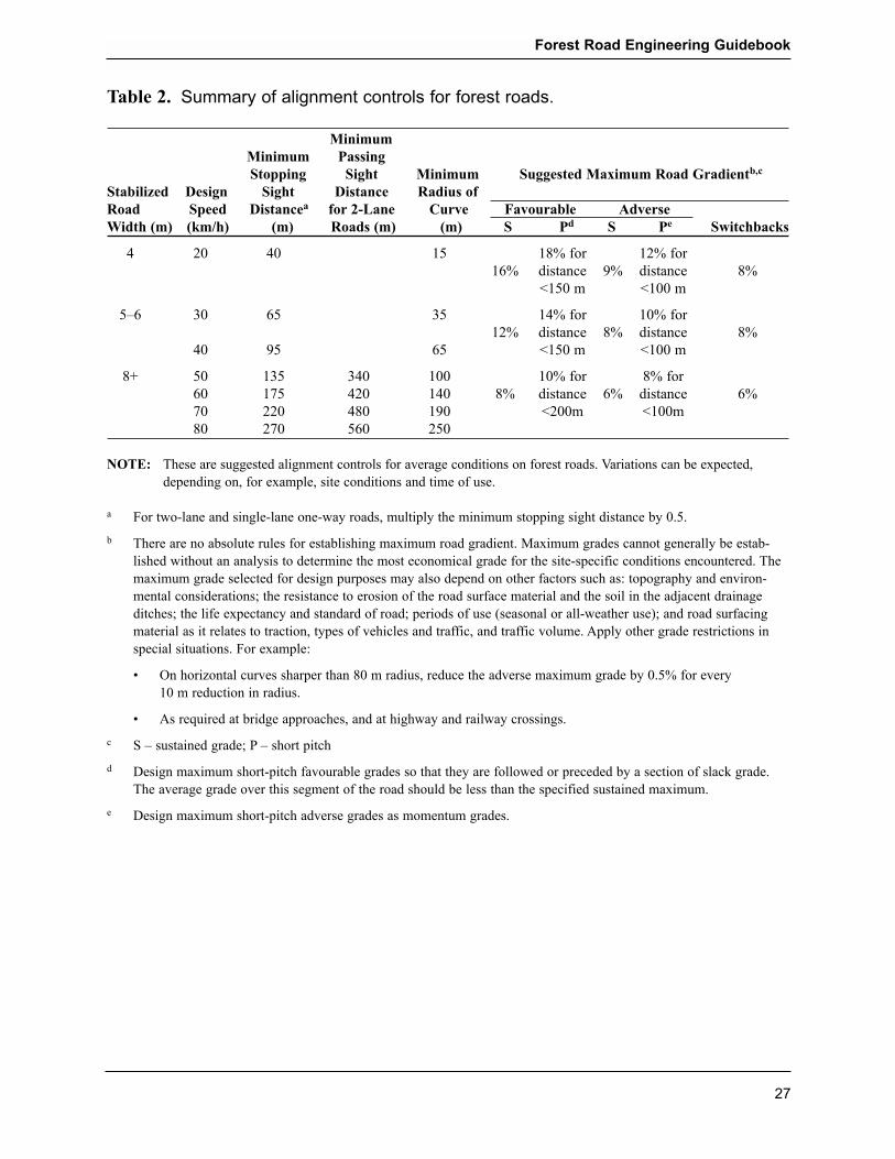
Table 2. Summary of alignment controls for forest roads.
MinimumMinimum PassingStopping Sight Minimum Suggested Maximum Road Gradientb,c
Stabilized Design Sight Distance Radius ofRoad Speed Distancea for 2-Lane Curve Favourable AdverseWidth (m) (km/h) (m) Roads (m) (m) S Pd S Pe Switchbacks
4 20 40 15 18% for 12% for16% distance 9% distance 8%
<150 m <100 m
5�6 30 65 35 14% for 10% for12% distance 8% distance 8%
40 95 65 <150 m <100 m
8+ 50 135 340 100 10% for 8% for60 175 420 140 8% distance 6% distance 6%70 220 480 190 <200m <100m80 270 560 250
NOTE: These are suggested alignment controls for average conditions on forest roads. Variations can be expected,depending on, for example, site conditions and time of use.
a For two-lane and single-lane one-way roads, multiply the minimum stopping sight distance by 0.5.
b There are no absolute rules for establishing maximum road gradient. Maximum grades cannot generally be estab-lished without an analysis to determine the most economical grade for the site-specific conditions encountered. Themaximum grade selected for design purposes may also depend on other factors such as: topography and environ-mental considerations; the resistance to erosion of the road surface material and the soil in the adjacent drainageditches; the life expectancy and standard of road; periods of use (seasonal or all-weather use); and road surfacingmaterial as it relates to traction, types of vehicles and traffic, and traffic volume. Apply other grade restrictions inspecial situations. For example:
� On horizontal curves sharper than 80 m radius, reduce the adverse maximum grade by 0.5% for every 10 m reduction in radius.
� As required at bridge approaches, and at highway and railway crossings.
c S � sustained grade; P � short pitch
d Design maximum short-pitch favourable grades so that they are followed or preceded by a section of slack grade.The average grade over this segment of the road should be less than the specified sustained maximum.
e Design maximum short-pitch adverse grades as momentum grades.
Forest Road Engineering Guidebook
27

Table 3. Minimum subgrade widths for roads on curves, for pole andtri-axle trailer configurations, and for lowbed vehicles.
Pole and Tri-axle Trailer Configuration Lowbed Vehicles
Radius Minimum Subgrade Minimum Subgradeof Curve (m) Width (m) Width (m)
180 4.0 4.390 4.5 5.360 5.0 5.845 5.0 6.035 5.5 6.525 6.0 7.520 7.0 8.015 8.0 9.0
NOTES:
� The subgrade widths in this table do not allow for the overhang of long logs or any slippage ofthe truck or trailer due to poor road conditions.
� Apply the widening to the inside of the curve unless the curve has a 60 m long taper sectionon each end. For widening on the inside, provide a minimum 10 m section on each end of thecurve.
� For two-lane roads or turnouts, it is assumed that the second vehicle is a car or single-unittruck. Add 4.0 m for logging trailer configurations and 4.5 m for lowbed vehicles.
� Double-lane any blind curves or provide adequate traffic control devices.
Table 4. Recommended turnout widths, based on stabilized roadwidths.
Stabilized Turnout Widthb
Road Widtha Description (m)
9+ 2-lane off-highway none8 2-lane on-highway none6 1-lane off-highway 105 1-lane on/off-highway 8 to 104 1-lane on/off-highway 8
a Where no road surfacing is used, the stabilized road width is the width of the road subgrade.Sufficient room should be left on the low side to accommodate debris.
b Turnout width includes stabilized road width.
Forest Road Engineering Guidebook
28
Fill slope and cut slope angles
Stable cut slopes, road fills, borrow pits, quarries, and waste areas should bedesigned and constructed in a manner that will not contribute directly or indi-rectly to slope failures or landslides over the expected design life. Table 5provides general guidelines for cut and fill slope angles for use in forest roaddesign.
Fill slopes
The stability of a fill slope depends on several variables, including the forcesthat tend to cause instability (gravitational and water pressure forces), and theforces that tend to oppose instability (e.g., shear strength resistance of thesoil or rock materials expressed as an internal friction angle or cohesion).The stability of an embankment fill can be increased several ways:
� Construct the side slopes of fill embankments at a gentle angle, and usu-ally not steeper than the �angle of repose.� The term �angle of repose�should be used in the context of loose, cohesionless soils only (e.g., non-plastic silt, sand, sand and gravel). Constructing flatter side slopes in alltypes of soil will reduce the gravitational forces that tend to cause slopeinstability. For a fill slope in cohesionless material, the angle of repose isabout the same as the minimum value of that material�s angle of internalfriction. Steeper fill slopes are more likely to cause a road-induced slopefailure or landslide than flatter fill slopes.
� Compact the fill materials to make them more dense and increase theshearing resistance of the soil. The angle of internal friction depends pri-marily on the relative density (loose versus dense), the particle shape(round versus angular), and the gradation (uniformly graded versus wellgraded). For relatively loose cohesionless soils, the minimum value of theangle of internal friction will range from about 27 degrees (2H : 1V) forrounded uniform soil grains to 37 degrees (11Ú3 H : 1V) for angular, well-graded soil grains. For relatively dense cohesionless soils, the maximumvalue of the angle of internal friction will range from about 35 degrees(11Ú2 H : 1V) for rounded uniform soil grains to 45 degrees (1H : 1V) forangular, well-graded soil grains.
Note: Fill slopes that are constructed at or less than the angle of repose(minimum angle of internal friction) will not necessarily remain stable ifpartial or full saturation of the fill occurs. Such saturation can result fromsurface and subsurface water flows during spring melt or after heavyperiods of rainfall.
� Where necessary, provide good drainage of the fill to reduce the build-upof water pressure forces along potential planes of sliding within the fill.Expect that poorly drained fill materials will be prone to a greater likeli-hood of slope failure or sloughing than well-drained fill materials.Additionally, the slopes of poorly drained fills at locations of significant
Forest Road Engineering Guidebook
29
zones of ground water seepage may experience larger and greater fre-quency of slope failures or sloughing problems. The significance ofobserved seepage zones might dictate the application of special drainagemeasures to reduce the likelihood of slope failure during construction andthe intensity of maintenance activities over the operating life of the road.As a general rule, without special drainage measures, the side slopes ofpoorly drained fills (e.g., fills composed of silty soils) should be con-structed at angles that are flatter than the angle of repose to minimize thelikelihood of slope failures.
Cut slopes
The design of cut slopes should consider and address factors such as thedesired performance of the cut slopes, types of cut slope materials, issuesabout overall terrain stability, engineering properties of soils, seepage condi-tions, construction methods, and maintenance. In general, cut slopes willremain stable at slightly steeper angles than fill slopes constructed from likesoil materials. The reason for this is the undisturbed soil materials in a cut (1) are often in a denser state than similar type materials placed in a fill, and(2) may contain sources of cohesive strength that further increases the shear-ing resistance of the soil.
Cut slopes constructed at too flat an angle can be uneconomical in steepground because of the large volumes of excavation. Steeper cut slopes maybe more economical to construct in terms of reduced volumes of excavation.However, they can also be more costly from an operational standpointbecause they require more road maintenance.
For most forest roads, cut slope angles are generally designed to favoursteeper angles to reduce the length of cut slopes, to minimize visible site dis-turbance, and to reduce excavation costs, provided that a somewhat higherlevel of road maintenance and likelihood of slope destabilization is accept-able for the site.
In the latter case, prepare and implement a maintenance schedule thataddresses the erosional processes acting on the exposed cut slope face (suchas splash, sheet, rill, and gully erosion) and reduces the threat to drainagesystems (as a result of cut bank slope failure redirecting ditchwater flowsonto potentially unstable fill or natural slopes), user safety, and the environ-ment.
It may be necessary to construct flatter cut and fill slopes, or to build retain-ing wall structures to support cut slopes or fill slopes, in cases where slopestability problems are expected to be difficult to manage with maintenancemeasures alone.
Forest Road Engineering Guidebook
30
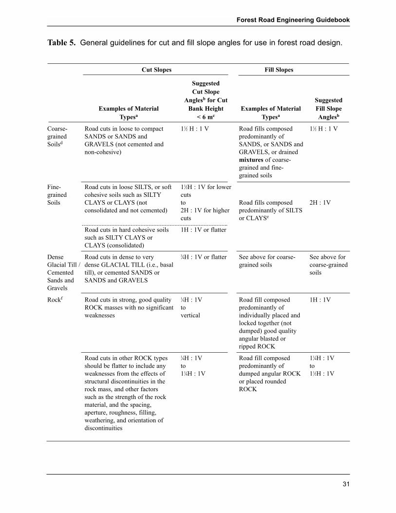
Table 5. General guidelines for cut and fill slope angles for use in forest road design.
Cut Slopes Fill Slopes
SuggestedCut Slope
Anglesb for Cut SuggestedExamples of Material Bank Height Examples of Material Fill Slope
Typesa < 6 mc Typesa Anglesb
Coarse- Road cuts in loose to compact 11Ú2 H : 1 V Road fills composed 11Ú2 H : 1 Vgrained SANDS or SANDS and predominantly ofSoilsd GRAVELS (not cemented and SANDS, or SANDS and
non-cohesive) GRAVELS, or drained mixtures of coarse-grained and fine-grained soils
Fine- Road cuts in loose SILTS, or soft 11Ú2H : 1V for lowergrained cohesive soils such as SILTY cutsSoils CLAYS or CLAYS (not to Road fills composed 2H : 1V
consolidated and not cemented) 2H : 1V for higher predominantly of SILTScuts or CLAYSe
Road cuts in hard cohesive soils 1H : 1V or flattersuch as SILTY CLAYS or CLAYS (consolidated)
Dense Road cuts in dense to very 3Ú4H : 1V or flatter See above for coarse- See above forGlacial Till / dense GLACIAL TILL (i.e., basal grained soils coarse-grainedCemented till), or cemented SANDS or soilsSands and SANDS and GRAVELSGravels
Rockf Road cuts in strong, good quality 1Ú4H : 1V Road fill composed 1H : 1VROCK masses with no significant to predominantly of weaknesses vertical individually placed and
locked together (notdumped) good qualityangular blasted or ripped ROCK
Road cuts in other ROCK types 1Ú4H : 1V Road fill composed 11Ú4H : 1Vshould be flatter to include any to predominantly of toweaknesses from the effects of 11Ú4H : 1V dumped angular ROCK 11Ú2H : 1Vstructural discontinuities in the or placed rounded rock mass, and other factors ROCKsuch as the strength of the rockmaterial, and the spacing,aperture, roughness, filling,weathering, and orientation ofdiscontinuities
Forest Road Engineering Guidebook
31

Notes for Table 5:
a Not all material types in the soil groups are represented in the table.
b For the design of roads located in domestic watersheds, on sensitive terrain, or in other areas
where transport of sediment or landslides may adversely affect resources, it may be necessary
to use flatter cut and fill slope angles to reduce the hazard of erosion or failure of cut and fill
slopes. During construction of roads, it may be necessary to build flatter slopes where the road
prism exhibits signs of distress, such as, for example: (1) cracks or scarps within original
ground above the top of cut slopes, in the road surface, or within the fill slope on the downslope
side of the road; and (2) significant zones of ground water seepage such that localized failure
of cut or fill slopes are expected. Alternatively, installation of retaining wall structures may be
needed to reduce excavation, contain bank material, or prevent slope failure. The significance
of observed seepage zones might dictate application of other special measures to reduce the
likelihood of slope failure during construction and over the operating life of the road.
c Consider the need to obtain advice from a qualified registered professional for cut heights
greater than 6 m. The advantages of steeper cuts may include: less area occupied by road; less
excavated material; less sidecast; and shorter slope lengths exposed to erosion processes. The
disadvantages of steeper cuts may include: increased difficulty to establish vegetation;
increased chance of slope ravelling, tension crack development and slope failure; and
increased road maintenance costs. The disadvantages of steeper cut slopes can be reduced if
high banks are avoided.
d Erosion control may be particularly problematic for slopes composed of sand, silty sands, or
silts. Consider the need for erosion protection measures for cut slopes, fill slopes, and ditches,
such as revegetation, soil bioengineering and biotechnical slope stabilization techniques, rip
rap, or other special slope treatments.
e If significant compaction of the road fills can be achieved, then fill slopes (of limited height)
may be placed steeper than 2H : 1V.
f If potential problems are anticipated for rock slopes either during design, construction, mainte-
nance, or deactivation, consult with a geotechnical engineer or other rock slope specialist. It
may be necessary to address the need for special rock slope stabilization measures (e.g., rock-
fall catch ditch, wire mesh slope protection, shotcrete, rock bolts).
Forest Road Engineering Guidebook
32

Clearing widths
Clearing widths should be as narrow as possible, to minimize impacts onother resources, but wide enough to accommodate:
� the road prism
� user safety
� turnouts
� subgrade drainage
� subgrade stability
� waste areas and endhaul areas
� pits and quarries
� landings
� slash disposal
� equipment operation
� snow removal
� fencing and other structures
� standing timber root protection, especially on cut banks.
Organic debris, rock, or any other excess material that cannot be placed inthe road prism and within the clearing width because of terrain stability orother factors should be moved to waste areas. Such areas should be of suit-able size to accommodate the estimated volume of waste material and shouldbe identified in the road design.
Clearing widths are calculated on a station-by-station basis as part of a geo-metric road design. In situations where geometric road design is not required,other methods can be used. For further details, see Chapter 3, �RoadConstruction� and clearing width tables in Appendix 5.
Culvert drainage design
Refer to Chapter 4, �Road Drainage Construction,� for guidance on culvertdrainage design.
Other structures
A professional engineer must take design responsibility for cattleguard fabri-cation, the construction or modification of retaining walls greater than 1.5 mhigh, and the design of other specialized structures that fall within the prac-tice of a professional engineer.
Forest Road Engineering Guidebook
33
Suggestions for further reading
British Columbia Institute of Technology (BCIT). 1984. Manual for Roadsand Transportation. Vol. 1 and 2. Burnaby, B.C.
____________. 1992. Soil Mechanics. Seminar Manual. RRET 271.Burnaby, B.C.
____________. 1995. Road Construction Practices and Procedures. SeminarManual. RRET 0310/0311. Burnaby, B.C.
British Columbia Ministry of Agriculture and Food, B.C. Ministry of Forests,and B.C. Ministry of Transportation and Highways. 2001. CattleguardStandards and Specifications. Victoria, B.C.
British Columbia Ministry of Forests, Resource Inventory Committee. 1996.Terrain Stability Mapping in British Columbia: A Review and SuggestedMethods for Landslide Hazard and Risk Mapping. Publication 055.Victoria, B.C.
____________. 1999. Mapping and Assessing Terrain Stability FieldAssessment Guidebook, 2nd. ed. Victoria, B.C.
Canadian Geotechnical Society. Canadian Foundation Engineering Manual3rd Edition (1992). Richmond, B.C.
Canadian Standards Association. 1997. Risk Management: Guideline forDecision-makers. National Standard of Canada CAN/CSA-Q850-97.
Chatwin, S.C., D.E. Howes, J.W. Schwab, and D.N. Swanston. 1994. A guidefor management of landslide-prone terrain in the Pacific Northwest. LandManagement Handbook No. 18. 2nd ed. B.C. Ministry of Forests,Victoria, B.C. 220 p.
Fell, R. and D. Hardford. 1997. Landslide risk management. Landslide RiskAssessment: Proceedings of the International Workshop on LandslideRisk Assessment, Honolulu, Hawaii, February 19-21, 1997. D.M. Crudenand R. Fell (editors). A.A. Balkema, Rotterdam, Brookfield, p.51-109.
Garland, J. October 2001. EESC9, The Woodland Workbook: DesigningWoodland Roads. Oregon State University Extension Service, Corvallis,Oreg.
Roads and Transportation Association of Canada (RTAC). 1999. Manual ofGeometric Design Standards for Canadian Roads. Ottawa, Ont.
Forest Road Engineering Guidebook
34

Transportation Research Board, National Research Council. 1996.Landslides: Investigation and Mitigation. Special Report 247. A.K. Turner and R.L. Schuster (editors). National Research Council(U.S.) Transportation Research Board, Washington, D.C.
Workers� Compensation Board of British Columbia. 2001. Fallers� andBuckers� Handbook. Vancouver, B.C.
Forest Road Engineering Guidebook
35

Forest Road Engineering Guidebook
36

2. Design and Construction of Bridges and Stream Culverts
Introduction
This chapter describes some of the activities and practices that precede andfollow the construction of forest road bridges and stream culverts. Theseinclude:
� design requirements for bridges and stream culverts
� bridge and major culvert design responsibility
� site data and survey requirements for bridges and major culverts
� construction drawings and specifications for bridges, major culverts, andstream culverts on fish streams
� site data and survey requirements for culverts on non�fish-bearingstreams
� estimating design discharge for streams
� statement of construction conformance and documentation.
The Forest Service Bridge Design and Construction Manual (B.C. Ministryof Forests 1999) provides further discussion on planning, design, and con-struction of forest road bridges.
Consistent with the Forest Road Regulation, in this chapter:
� �bridge� means a temporary or permanent structure carrying a road abovea stream or other opening
� �culvert� means a transverse drain pipe or log structure covered with soiland lying below the road surface
� �cross-drain culvert� means a culvert used to carry ditchwater from oneside of the road to the other
� �major culvert� means a stream culvert having a pipe diameter of 2000mm or greater, or a maximum design discharge of 6 m3/sec or greater
� �stream culvert� means a culvert used to carry stream flow in anephemeral or perennial stream channel from one side of the road to theother.
Refer to Chapter 4, �Road Drainage Construction� for further information onforest road drainage systems including; temporary stream crossings, ditchconstruction and cross-drain culverts, log culvert design and construction,and ford design and construction.
Forest Road Engineering Guidebook
37

Design requirements for bridges and stream culverts
The design of bridges and stream culverts encompasses more than the designof structural components. A bridge or stream culvert design should considerthe composition and interaction of all the components, as well as their rela-tionship and impact to the users, road, and stream. A bridge comprises thesuperstructure, substructure, connections, vertical and horizontal alignmentcontrols, approach road fills, and scour protection works. Similarly, a streamculvert comprises the culvert materials, compacted backfill, scour protection,and roadway. Bridge or stream culvert designs include, but are not limited to,consideration of:
� user safety
� site selection
� environmental integrity
� fish habitat and passage
� impact of proposed structure on stream during and after construction
� site revegetation requirements
� structure alignment and location (vertical and horizontal) relative to theroad and stream channel
� complete structure combination (substructure, superstructure, connections,and scour protection)
� suitability of selected foundations for the specific site
� design flood development
� navigation (Navigable Waters Act)
� debris potential and passage
� scour protection
� design vehicle configuration for load and alignment
� design service life influence on selection of bridge type and composition
� construction layout, methodology, and timing
� economics.
Bridge and major culvert design responsibility
Bridge designs should clearly identify who is taking overall design responsi-bility (whether a professional engineer, professional forester, or non-professional) for ensuring that all aspects of the design have been appropri-ately addressed. In addition, a person required to prepare a road layout anddesign must ensure that a professional engineer takes design responsibilityfor major culverts.
Forest Road Engineering Guidebook
38

Non-professional and professional forester bridge design
Subject to specified constraints, a role is recognized for non-professionalsand professional foresters with considerable experience in designing and con-structing shorter, single-span structures. These are non-complex, standardwidth, non-composite structures, with relatively straight road alignments.They are constructed with conventional materials, on simple abutment sup-ports, founded on excavations in original ground or on a shallow ballastlayer. A professional engineer should assume responsibility for design oflonger spans, higher abutments, and more complex bridge structures.
Bridge design limitations
Design by non-professionals is limited to single spans with a maximum of 6 m centre-to-centre of bearing. Professional foresters are limited to single-span bridges with 12 m centre-to-centre of bearing or less.
For non-professional design, rip rap should not be required, as all bridgecomponents (including rip rap or scour protection) are located outside of thedesign flood wetted perimeter. Where any components infringe or potentiallyinfringe on the design flood wetted perimeter, design flood forces on thesecomponents should be considered and this part of the design must be com-pleted by a professional engineer.
The stream should be historically stable, in a well-defined channel, with erosion-resistant banks, which are not subject to erosion or shifting in floodflows, such as would be the case on an alluvial fan.
The bridge abutments must be constructed on or below original ground or ona shallow ballast layer. This shallow ballast layer is intended to act only as alevelling surface to provide full bearing.
Note that the bridge superstructure must be non-composite. A compositebridge is one where a deck and girders are intimately connected such thatthey act as a unit to support the design load. These complex structuresrequire a greater level of technical knowledge with respect to design andinstallation. Other structures included in this category are those with compo-nents that do not act independently of each other, such as concrete slab orbox girders with welded or grouted shear connectors, or structures requiringfield welding during installation.
Note also that welding is influenced by many factors, including: welder train-ing and experience, type of weld (such as: rectangular groove, flat, verticaloverhead, fillet, butt), welding equipment, welding rods, welding rate, ambi-ent temperature and moisture, materials being welded, and so on. It is notpossible to fully gauge the adequacy of a weld through only visual inspec-tion. Since many structures require field welds, anyone considering designand erection of welded structures should ensure that persons with adequate
Forest Road Engineering Guidebook
39
training and experience are involved and responsible for all aspects of welddesign and welding procedures.
Where shop or field welding is required, designs should indicate the minimumqualifications required. Use of Canadian Welding Bureau (CWB) certifiedfirms and qualified welders is recommended.
Abutment heights, from the foundation level to the top of the abutment onwhich the superstructure would bear, are limited to log cribs less than 4 m inheight or sills or pads up to 1.5 m in height. For log cribs, the 4 m heightlimitation is measured from the bottom of abutment where it bears on theground to the top of the bearing sill or bridge soffit (underside of bridgesuperstructure).
Abutments that are not log cribs are limited to 1.5 m in height. Sills and capsare transitions to connect the superstructure to the substructure. They are notconsidered part of the maximum allowable abutment height, provided thetransition depth is not excessive (a maximum sill or cap height of 400 mm issuggested), and that the sills, caps, and the connections have been producedfrom design aids prepared by a professional engineer for use in the proposedconfiguration.
Note that abutment heights are not cumulative; for example, a 1.5 m abutmentis not intended to be designed to bear on top of a log crib or its fill. Binwallsare not considered log crib equivalents. Binwall abutments are more complex,requiring bearing of sills or pads on significant compacted fill depths, andmust be designed by a professional engineer.
Bridge designs by non-professionals and professional foresters must be pre-pared using structural details provided in drawings, tables, charts, and otherdesign aids that have been prepared by a professional engineer. Each bridgeor major culvert must have its own site-specific design. The bridge compo-nents (superstructure, substructure, connections) must all have been designedto be used in the specific combination and configuration shown in the design.Any design aids used should be referenced on the design drawings orattached documentation.
Where portable bridges are used, the structure must have been designed orstructurally analyzed by a professional engineer. The design or analysisshould demonstrate adequacy for the intended use. Once the structure hasbeen reviewed and approved by a professional engineer, the structure may bereused at new sites without specific professional engineer review, providedthat:
� a qualified inspector has inspected the bridge at the new site before anyuse and detects no damage or deterioration of the structure;
Forest Road Engineering Guidebook
40

� the design loads to be carried should be equal to or lower than originaldesign loads; and
� the bridge is suitable and has been specifically designed for the new site,and the superstructure has been fabricated and constructed in compliancewith the Forest Road Regulation.
The professional engineer, professional forester, or person assuming respon-sibility must sign off on the design for the bridge or major culvert andbecomes the designer of record.
Site data and survey requirements for bridges and major culverts
The person assuming design responsibility for a bridge or major culvertrequires site-specific information for the proposed crossing. A detailed sitesurvey (see Appendix E, �Bridge and Major Culvert Site Plan Specifications�in the Forest Service Bridge Design and Construction Manual) is recom-mended for all bridges and major culverts. The survey information is used toproduce site plan and profile drawings for planning, developing, and evaluat-ing the crossing design. Direction for the type and quality of site informationto be collected and the site survey to be completed should be obtained fromthe designer. Included should be:
� the riparian class for streams or lake classification
� the apparent high water elevation of the stream, based on visible evidenceof recent flooding
� a description of the composition and size of stream bed materials
� a description of stream bank materials and stream stability
� cross-sections and a profile of the crossing
� the stream flow velocity and direction, if the flow may influence the sizeor layout of the structure
� a description of the soil profiles and foundation soil conditions, based onsoil explorations appropriate to the level of risk
� presence (or absence) of bedrock, and depth to, bedrock
� a description of any evidence of stream debris or slope instability thatcould affect the crossing, based on upstream observations
� any existing improvements or resource values in the vicinity that mayinfluence the size or layout of the structure.
� if there is an existing structure, location and dimensions of the structure,including roadway, abutment, superstructure, and stream information
� the date of the survey
� the locations and dimensions of any upstream structures, and a note aboutwhether they are problem-free
Forest Road Engineering Guidebook
41

� any other pertinent information: Is the site currently accessible by road?Are there road or bridge restrictions on load length or weight? How canthese be overcome? If test drilling seems likely, how much work isrequired to get a drilling truck (usually not all-wheel drive) to the site?
� if equipment fording will be necessary for construction, informationabout possible ford locations and other considerations such as depth ofstream at that point, bottom material, and access gradients
If a fish stream is involved, the Fish-stream Crossing Guidebook (B.C.Ministry of Forests 2002) should be consulted for additional site require-ments.
Construction drawings and specifications
General arrangement drawings are the outcome of the design process andshow the location, composition, and arrangement of the proposed structure inrelation to the crossing. Site plan and profile drawings are design aids fromwhich a proposed design is developed; they are not general arrangementdrawings.
A set of construction drawings consists of the general arrangement drawingssupplemented with detailed superstructure and substructure drawings andother fabrication, material, and construction specifications. Shop drawingsare prepared by material fabricators to detail, and in many cases complete thestructural design of bridge structure components. These drawings will formpart of the construction drawing set and should be retained as part of the as-built documentation. The complete construction drawing set should providecomprehensive details on the location, composition, arrangement, designparameters, and fabrication, materials, and construction specifications for thespecific proposed structure and is intended to be an integral part of the plan-ning process, completed before construction begins.
Typical scales for bridge and major culvert design and construction drawingsare 1:200, 1:100, and 1:50. The construction drawings should clearly showall construction details and enable installation in general conformance withthe design intent. Where appropriate, a smaller scale should be used forgreater detail.
General bridge arrangement drawing requirements
General arrangement drawings should clearly depict the proposed compo-nents and configuration of the bridge or major culvert in relation to the forestroad, stream, and stream banks. These drawings may also be used during theagency referral process. Further details can be found in the Forest ServiceBridge Design and Construction Manual.
Forest Road Engineering Guidebook
42

Recommended contents for bridge and major culvert general arrangementdrawings comprise:
� designer�s name (and seal, if applicable)
� name of the stream, road, and station (km) and adequate information todetail the location of the structure
� design vehicle configuration for load and alignment
� design code references�specifically, those from the most recent versionof the Canadian Highway Bridge Design Code and the CanadianFoundation Engineering Manual
� expected life of the structure in place (temporary or permanent)
� design high water elevation for bridges
� clearances between the design high water level and soffit (low point ofunderside of superstructure) of bridges
� details of debris passage or management strategies, if required
� road approaches, including width requirements (including allowance forvehicle side tracking) and side slopes, to a sufficient distance back fromthe bridge to show problems, or to the end of the first cut or fill
� dimensioning and labelling of component parts
� drawings scales
� relevant site plan and profile data; for suggested contents see above section on �Site data and survey requirements for bridges and major culverts� (sample general arrangement drawings are shown in Figures 4 and 5)
� location (vertical and horizontal) of proposed structure relative to fieldreference points
� possible ford locations
� special provisions related to the unique nature of the site and crossing,including specific instructions to bidders related to process or results, asappropriate
� references to specific design drawings or design aids used.
Forest Road Engineering Guidebook
43
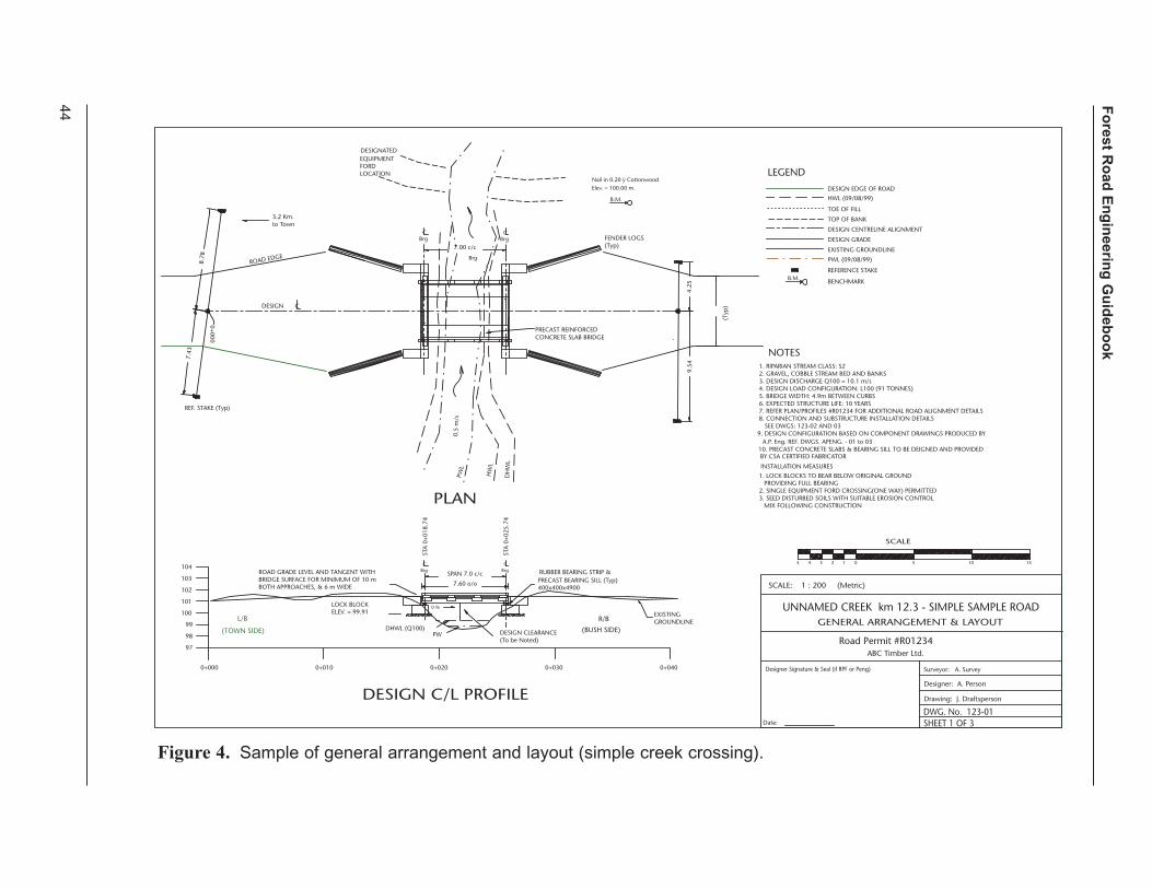
Fo
rest Ro
ad E
ng
ineerin
g G
uid
ebo
ok
44
(To be Noted)DESIGN CLEARANCE
0+000
97
101
100
99
98
104
103
102
0+010 0+020 0+030 0+040
UNNAMED CREEK km 12.3 - SIMPLE SAMPLE ROADGENERAL ARRANGEMENT & LAYOUT
LEGEND
NOTES
REF. STAKE (Typ)
ROAD GRADE LEVEL AND TANGENT WITHBRIDGE SURFACE FOR MINIMUM OF 10 mBOTH APPROACHES, & 6 m WIDE
ELEV. = 99.91LOCK BLOCK 0 %
BrgC
STA
0+0
18.7
4
PRECAST BEARING SILL (Typ)400x400x4900
BrgC
STA
0+0
25.7
4
GROUNDLINEEXISTING
DESIGN C
CBrg
Nail in 0.20 ÿ CottonwoodElev. = 100.00 m.
PRECAST REINFORCED
BrgC
0+000
B.M.
3.2 Km.to Town
EQUIPMENTFORDLOCATION
PWL
HW
L
DH
WL
SCALE: 1 : 200 (Metric)
ABC Timber Ltd.
Road Permit #R01234
Drawing: J. Draftsperson
DWG. No. 123-01
Designer: A. Person
SHEET 1 OF 3
Surveyor: A. Survey
DHWL (Q100)PW
FENDER LOGS(Typ)
1. RIPARIAN STREAM CLASS: S2 2. GRAVEL, COBBLE STREAM BED AND BANKS 3. DESIGN DISCHARGE Q100 = 10.1 m/s 4. DESIGN LOAD CONFIGURATION: L100 (91 TONNES) 5. BRIDGE WIDTH: 4.9m BETWEEN CURBS 6. EXPECTED STRUCTURE LIFE: 10 YEARS 7. REFER PLAN/PROFILES #R01234 FOR ADDITIONAL ROAD ALIGNMENT DETAILS 8. CONNECTION AND SUBSTRUCTURE INSTALLATION DETAILS SEE DWGS: 123-02 AND 03
INSTALLATION MEASURES
1. LOCK BLOCKS TO BEAR BELOW ORIGINAL GROUND PROVIDING FULL BEARING 2. SINGLE EQUIPMENT FORD CROSSING(ONE WAY) PERMITTED 3. SEED DISTURBED SOILS WITH SUITABLE EROSION CONTROL MIX FOLLOWING CONSTRUCTION
DESIGN EDGE OF ROAD
TOP OF BANK
TOE OF FILL
BENCHMARK
HWL (09/08/99)
REFERENCE STAKE
PWL (09/08/99)
DESIGN GRADE
EXISTING GROUNDLINE
DESIGN CENTRELINE ALIGNMENT
Brg
B.M.
Designer Signature & Seal (if RPF or Peng)
Date:
ROAD EDGE
DESIGNATED
9. DESIGN CONFIGURATION BASED ON COMPONENT DRAWINGS PRODUCED BY
BY CSA CERTIFIED FABRICATOR0.
5 m
/s
(Typ
)
4 .2 5
9 .5 4
CONCRETE SLAB BRIDGE
8.78
7.43
A.P. Eng. REF. DWGS. APENG. - 01 to 0310. PRECAST CONCRETE SLABS & BEARING SILL TO BE DEIGNED AND PROVIDED
RUBBER BEARING STRIP &
7.60 o/o
SPAN 7.0 c/c
35 4 12 0 10
SCALE
5 15
7.00 c/c
PLAN
DESIGN C/L PROFILE
L/B R/B
(TOWN SIDE) (BUSH SIDE)
Figure 4. Sample of general arrangement and layout (simple creek crossing).

Fo
rest Ro
ad E
ng
ineerin
g G
uid
ebo
ok45
Figure 5. Sample of general arrangement and layout (complex creek crossing).
+0
040
+0
070
+0
060
+0
050
+0
030 +
0 0
20
COMPLEX CREEK km 0.3 - COMPLEX CREEK ROAD
GENERAL ARRANGEMENT & LAYOUT
LEGEND
NOTES
3.0
PROPOSED ROAD GRADE
ASSUMED APPROXIMATELINE OF EXCAVATION
STA
0+0
36.2
0
STA
0+0
52.2
0
DECK ELEV=99.36
=95.6FOOTING ELEV.
EXISTING ROAD GRADE
COMPACTION ZONETO 95 % SPD
BACKFILLDHWL (Q100)
CBrg
1
NON WOVEN GEOTEXTILEUNDERLAY (BOTH SIDES)
1.5
BrgC
DECK ELEV=99.10
FOOTING ELEV=95.5
BM 1 SPIKE IN0.3ÿ CEDARELEV.=100.00
3.5
CO
MPL
EX
CRE
EK
5.10m
DWG. No. ABC-01
ABC Timber Ltd.
Road Permit #R01234
SCALE: 1 : 200 (Metric)
Designer: A.P. Eng.
Drawing: J. Draftsperson
SHEET 1 OF 4
Surveyor: A. Survey
0
Rev.
DESIGN CENTRELINE ALIGNMENT
35 4 12 0 10
SCALE
5 15
COMPLEX CREEK FSR
1.3 Km. TO HWY
6.19m
REF STAKE(TYP)
EXISTING GROUNDLINE
DESIGN GRADE
PWL (09/08/99)
100 CONTOUR (CONTOUR INTERVAL IS 0.5m)
REFERENCE STAKE
HWL (09/08/99)
EXISTING LOG STRINGER BRIDGE
BENCHMARK
10∞ SKEW
CROSS SECTION `B'
DESIGN C/L
A
CROSS SECTION `A'
LCBRG
B
A
BRGCL
B
ELEV.=98.32
BM 2 SPIKE IN0.5ÿ FIR
6.24
6.255.84
100
PRECAST NON-COMPOSITE DECKON STEEL GIRDER BRIDGEWITH TIMBER CURBS
PRECAST BALLAST WALLS
PRECAST FOOTINGAND STEEL PIPEABUTMENT
PWL
1. RIPARIAN STREAM CLASS: S2
2. DESIGN DISCHARGE: Q100 = 22 m/s
8. EXISTING 10.2m TIMBER DECKED, LOG STRINGER BRIDGE ON 2m LOG CRIBS - TO BE REMOVED
9. ASSEMBLY AND INSTALLATION DETAILS SEE Dwgs. No. ABC-02 To 04
10. SCOUR PROTECTION DETAILS SEE Dwg. No. ABC-04
11. FOR SUPERSTRUCTURE & BEARING DETAILS SEE DESIGN Dwgs. No. SUP01 To 04
12. FOR SUBSTRUCTURE DETAILS SEEDESIGN Dwgs. No. SUB01 To 02
3
TOE OF FILL
TOP OF BANK
EXISTING EDGE OF ROAD
Designer Signature & Seal (P.Eng)
Date:
PWL
PWL
HW
L
HWL
HWL
PWL H
WL
PWL
3. DESIGN LIVE LOAD BCFS L75 (68 TONNES)
98
98
98
B.M.
B.M.
B.M.
5. BRIDGE WIDTH: 4.3m BETWEEN CURBS 6. EXPECTED DESIGN LIFE: 40 YEARS 7. REFER TO PLANS/PROFILES #R01234 FOR
ADDITIONAL ROAD ALIGNMENT DETAILS
STREAMBED BANKS: GRAVEL, SAND, & COBBLES
DESIGN CLEARANCE(To be Noted)
Trailer Wheelbase Front Overhang Rear Overhang Pin Offset
0 5.30 0.85 1.20 0.001 12.00 1.55 1.76
4. DESIGN TRACKING VEHICLE
PLAN
DESIGN C/L PROFILE
R/BL/B
L/B R/B
(BUSH SIDE) (TOWN SIDE)
0+070
94
96
98
100
102
0+060 0+0400+050 0+030 0+020
9897
16000 c/c1.4m
in.
Bridge superstructure drawing requirements
In addition to the general drawing requirements, the following elementsshould be detailed on bridge superstructure drawings:
� design code references�specifically, those in the latest edition of theCanadian Highway Bridge Design Code and the Canadian FoundationEngineering Manual
� materials specifications and CSA references, including but not limited to:
� steel grades, impact category, finish
� timber species, grades, preservative treatment
� concrete strength, slump, and air entrainment
� rip rap and geosynthetics
� bearing materials and connections
� superstructure elements, configuration, and connections
� dimensions and sizes of components
� girder or stringer arrangements and connections
� span lengths
� bridge and road width
� deck elevations at bridge ends
� road and bridge grades and alignment
� deck configuration, connections, and component elements
� curb and rail configuration, connections, and component elements
� field fabrication details.
Bridge substructure drawing requirements
The following information on foundation requirements should be detailed onthe bridge substructure drawings:
� abutment elements, configuration, and connections
� dimensions and sizes of components
� critical elevations of substructure components
� scour protection: dimensions, composition, extent of placement, designslope, and other considerations
� piers
� location and sizes of piles or posts
� pile driving specifications, minimum expected pile penetrations, set crite-ria, and required service level capacities
� bracing and sheathing configurations.
Forest Road Engineering Guidebook
46

Log bridge superstructure on log crib drawing requirements
Since log stringer and crib materials are variable in nature and finisheddimensions are not uniform, log bridge drawings will be somewhat schematic.Drawings should address layout, required component sizing, and connectiondetails.
The following should be indicated on the log bridge superstructure and logcrib drawings:
� schematic layout indicating width and span
� reference source for stringer and needle beam sizing
� minimum stringer, curb, and needle beam dimensions
� stringer, curb, needle beam, and crib logs specifications, includingspecies, quality characteristics of acceptable logs, and seasoning
� stringer to cap bearing details, including shim types and stringer and capbearing width and surface preparation
� dap details at log connections
� needle beam locations and connection details, if applicable
� space to add stringer, curb, and needle beam sizes as part of the as-builtrecord
� deck layout, indicating tie sizes and spacing, plank thickness, and con-nections
� other materials specifications, including sawn timber, hardware, andshims
� excavated depth relative to scour line for mudsill or bottom bearing log
� general layout and arrangement of front, wing wall, deadman, and tiebacklogs, and their connections to each other and to the bearing log or cap
� description of crib fill material
� layout and description of in-stream protection, if applicable
� rip rap protection layout and specifications (as required).
Major culvert and fish stream culvert drawing requirements
Drawings and notes for major culverts, and for stream culverts not classifiedas major culverts and installed on fish-bearing streams, should portray anddescribe the following:
� site plan (see previous section on �Site data and survey requirements forbridges and major culverts�)
� location of the culvert, such as a key map
� design vehicle load
Forest Road Engineering Guidebook
47

� fill height, depth of cover, and maximum and minimum cover require-ments
� design slopes of fill and rip rap
� culvert invert elevations at the inlet and outlet
� culvert specifications and dimensions�opening dimensions, length, cor-rugation profile, gauge, and material type
� site preparation requirements
� embedment requirements, including a description of the substrate and anyrock used to anchor the bed material in the pipe
� backfill and installation specifications
� installation camber
� culvert slope
� special attachments or modifications
� inlet requirements (rip rap layout, stilling basin, etc.)
� outlet requirements (rip rap layout, stilling basin, backwater weir for fishpassage)
� rip rap specifications, including dimensions and configuration
� design high water elevation and design discharge
� connection details for pipe sections
� any existing improvements and resource values in the vicinity of the cul-vert that would influence or be influenced by the structure.
Any of the foregoing requirements can be combined. For example, drawingsfor a log stringer bridge on timber piles can include the details from �Logbridge superstructure on log crib drawing requirements,� plus those from�Bridge substructure drawing requirements.�
Any additional requirements for a fish stream culvert should be included asspecified in the Fish-stream Crossing Guidebook.
Culverts on non�fish-bearing streams
A detailed site plan is usually not required for stream culverts not classifiedas major culverts or those installed on non�fish-bearing streams. However, aminimum amount of information should be recorded during the road locationsurvey to assist in sizing such a stream culvert for the 100-year flood return.Where conditions are such that there are complex horizontal and vertical orother control issues requiring higher-level design and installation procedures,detailed site plans are recommended.
Forest Road Engineering Guidebook
48

In planning the layout of the structure:
� Choose an appropriate location, along a stream reach with uniform oruniformly varying flow close to the proposed crossing, to measure across-section. Sketch the cross-section of the stream gully, showing evi-dence of the high water level, present water level, and the depth of thestream across the bottom. The cross-section should extend back from thestream an appropriate distance to show the terrain that affects the pro-posed crossing and road alignment.
� Note any visual evidence of high water.
� Measure and record the average gradient of the stream at the crossing andat the cross-section if the two are taken at different locations.
� Record the soil type, soil profile, parent material, and substrate materialat the crossing and describe the stream bottom.
� Describe the stream channel (debris loading, bank stability, crossing loca-tion on a fan, bedload problem, etc.).
If the site is a fish stream or a potential fish stream, the Fish-stream CrossingGuidebook should be consulted for site and design requirements.
Estimating design discharge for streams
The following guidelines apply to determining the design discharge forstreams for a particular recurrence interval. Establishing a return period pro-vides a benchmark of the relative risk to be attached to any particular design.
These guidelines should not preclude use of other reasonable and acceptedmethods for determining the design discharge. Professional engineers, who inthe course of carrying out their professional functions as designers of abridge or a major culvert (2000 mm or greater in diameter or with dischargesof 6 m3/sec or greater), are ultimately responsible for establishing the designdischarge for that structure. Others determining stream discharges should befamiliar with methods and their limitations, or consult those with training andexperience in stream discharge determination.
Factors affecting runoff
The runoff and behaviour of a stream depends on many factors, most ofwhich are not readily available or calculable, such as:
� rainfall (cloudbursts; hourly and daily maxima)
� snowpack depth and distribution, and snowmelt
� contributory watershed area, shape, and slope
� topography and aspect
� ground cover
Forest Road Engineering Guidebook
49

� soil and subsoil
� weather conditions
� harvesting and road or other upslope development
� drainage pattern (stream order, branchiness; lakes and swamps)
� stream channel shape, length, cross-section, slope, and �roughness.�
Because topography, soil, and climate combine in infinite variety, drainagefor specific sites should be designed individually from available data for eachsite. In addition, the designer should consult those who have long experiencein maintaining drainage structures in the area.
Some methodologies to estimate design flood discharge
There are too many analytical and empirical methods for estimating streamdischarge to be discussed at any length in this guidebook. Methodologiescommonly used involve:
� working from available evidence of flood flows in the specific stream;
� gathering evidence of flood flows in other streams, relating these to theirdrainage basin characteristics, and then, from the characteristics of thebasin under consideration, estimating a flood flow; or
� relating meteorological data to stream basin characteristics and estimatingflood flow through empirical methods.
The necessary data for these methodologies can be obtained from severalsources:
Site information: Site data at and adjacent to the proposed crossing can beused to determine the maximum flow. Records of culverts and bridges withinthe vicinity that have successfully withstood known flood events can be usedto develop flood flows.
Stream basin characteristics: Stream basin characteristics such as length,slope, order, roughness, vegetative characteristics, and elevation band, com-bined with meteorological data, can be used in empirical approaches to deter-mine design flood flows.
Data on other streams: Studies done on other streams in the vicinity, withsimilar characteristics, can provide relationships and comparative values.
Hydrometric records: The Water Survey of Canada provides, in its SurfaceWater Data, annual reports of readings on hydrometric stations throughoutthe province. In addition, it publishes Historical Stream Flow Summaries inwhich mean values and annual peaks are tabulated. These stream flowrecords can be used to project design flood flows from theoretical analysis.
Forest Road Engineering Guidebook
50

Comparing discharges using hydrological information
Determining design flood discharge usually involves applying several differ-ent methods and then using judgement to select an appropriate design value.In all stream flood discharge determinations, it is prudent to compare the pro-posed opening size with historically problem-free existing stream crossingsserving similar drainages in the same area.
The designer should compare the flood discharge estimates derived from thesite information with other data and theoretical derivations. The final selec-tion of design discharge and resulting bridge opening or major culvert sizeshould then be based on the designer�s judgement, taking into account thesecomparisons, together with consideration of debris potential, ice jams, orother local factors that might influence the structure opening.
High water estimation method for stream culverts
Application of this method for determining the Q100 from site informationshould be limited to non-major stream culverts�less than 2000 mm in diam-eter or less than 6 m3/s design discharge. It is not appropriate for use as thesole method for �professional� designs.
This method assumes that the high water width represents the mean annualflood cross-sectional flow area for the stream (Q2); and that the Q100 cross-sectional flow area is three times this. It also assumes that the discharge isnot sensitive to influences from pipe slope, roughness, or other factors. These assumptions are not truly representative of all situations, but, withinthe accuracy expected for establishing design discharge, should be acceptablefor sizing stream culverts smaller than 2000 mm diameter or 6 m3/s on forestroads.
The high water width is defined as the horizontal distance between thestream banks on opposite sides of the stream, measured at right angles to thegeneral orientation of the banks. The point on each bank from which width ismeasured is usually indicated by a definite change in vegetation and sedimenttexture. Above this border, the soils and terrestrial plants appear undisturbedby recent stream erosion. Below this border, the banks typically show signsof both scouring and sediment deposition. The high water width should bedetermined from recent visible high-water mark indicators, which wouldapproximate the mean annual flood cross-section. This point is not necessari-ly the top of bank, particularly in the case of an incised stream.
� Locate a relatively uniform stream reach in close proximity to the pro-posed culvert location. Note that this not an averaging process that wouldbe used for determining the stream channel width for the purpose ofassessing stream habitat impacts. A uniform stream reach would have aconsistent cross-section, bed materials, and channel slope. It would alsobe relatively straight.
Forest Road Engineering Guidebook
51

� Estimate the visible high water stream width and cross-sectional area.
a) Measure (in metres) the high water width at a relatively uniformreach of the stream, representative of the mean annual flood (W1) andat the stream bottom (W2) (see Figure 6).
b) Measure the depth of the stream at several spots across the opening toobtain the average depth (D) in metres.
c) Calculate the cross-sectional area of the stream, A = (W1 + W2)/2 × D.
� Calculate the area of the required culvert opening, Ac = A × 3.0.
� Size the pipe (see Table 6), using the smallest pipe area that exceeds therequired area, or select an opening size for a log culvert that will begreater than Ac.
The high water width method can be cross-checked if field or other evidenceof an approximate 10-year flood is available. In this case, the area of the Q10flood can be multiplied by 2 to estimate the minimum culvert area for theQ100 flood.
Example
If W1 = 1.2 mW2 = 0.8 mD = 0.5 mstream cross-sectional area A = 0.5 m2
Then Ac = 0.5 × 3.0 = 1.5 m2
Therefore (from Table 6), the required pipe culvert size = 1400 mm.
Forest Road Engineering Guidebook
52
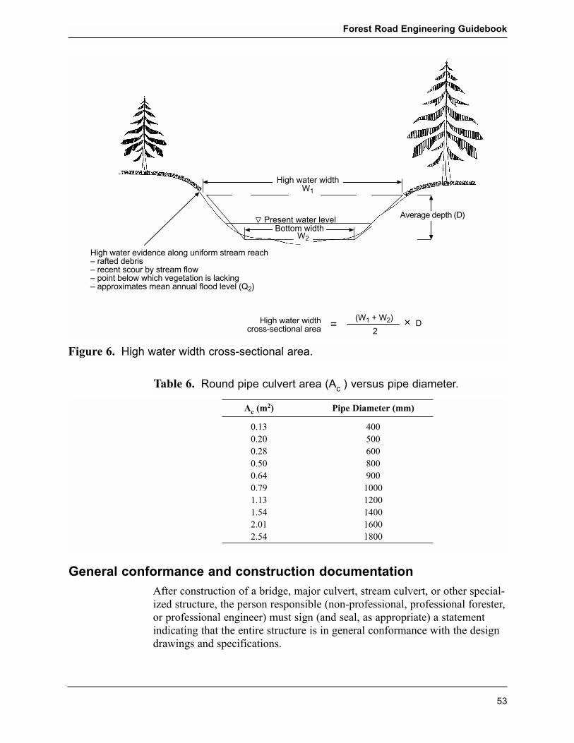
General conformance and construction documentation
After construction of a bridge, major culvert, stream culvert, or other special-ized structure, the person responsible (non-professional, professional forester,or professional engineer) must sign (and seal, as appropriate) a statementindicating that the entire structure is in general conformance with the designdrawings and specifications.
Forest Road Engineering Guidebook
53
High water widthW1
High water evidence along uniform stream reach� rafted debris� recent scour by stream flow� point below which vegetation is lacking� approximates mean annual flood level (Q2)
Bottom widthPresent water level
Average depth (D)
High water widthcross-sectional area =
(W1 + W2)
2× D
W2
Figure 6. High water width cross-sectional area.
Ac (m2) Pipe Diameter (mm)
0.13 4000.20 5000.28 6000.50 8000.64 9000.79 10001.13 12001.54 14002.01 16002.54 1800
Table 6. Round pipe culvert area (Ac ) versus pipe diameter.

Where a professional forester has taken design responsibility for a bridge, a professional forester or a professional engineer must provide a signed andsealed statement that the bridge is in general conformance with the designdrawings and specifications.
Where a professional engineer has taken design responsibility for a bridge, a professional engineer must provide a signed and sealed statement that thebridge is in general conformance with the design drawings and specifica-tions.
A sample statement of construction conformance is located in Appendix 4.
Documentation of materials used, and as-built records for the bridge or majorculvert, should be obtained during fabrication and construction. The personresponsible for construction should obtain and retain as-built records, includ-ing:
� any pile driving records, hammer type, penetration, set criteria, etc.
� fabrication plant inspection reports, including mill test certificates, con-crete test results, etc.
� shop or as-built fabrication drawings
� concrete and grout test results
� field compaction results
� other pertinent fabrication, field, and construction data.
As-built drawings are the �approved for construction� drawings�which maybe the approved design drawings�marked up to show all significant varia-tions from the original design. For example, mark-ups would show as con-structed details such as precise location in plan, finished pile depths, footingelevations, deck and other finished elevations, finished dimensions, and con-figurations of components. The as-built drawings should be signed (andsealed, where applicable) by the individual taking responsibility for the as-con-structed structure being in general conformance with the design. Where theoriginal design has been modified, these drawings should have been amendedby the designer, before inserting the as-built notes and details.
The as-built drawings, materials records, fabrication documentation, andother field and construction documentation must be retained for the life ofthe structure.
Forest Road Engineering Guidebook
54

Suggestions for further reading
American Iron and Steel Institute. 1984 (3rd Printing, May 1995). Handbookof Steel Drainage & Highway Construction Products. Canadian Edition.New York, N.Y.
British Columbia Ministry of Forests. 2002. Fish-stream CrossingGuidebook. Victoria, B.C.
____________. 1981. Log Bridge Stringers and Needle Beam Sizing (MetricEdition). Victoria, B.C.
____________. 1999. Forest Service Bridge Design and ConstructionManual. Victoria, B.C.
Canadian Geotechnical Society. 1992. Canadian Foundation EngineeringManual. Richmond, B.C.
Canadian Standards Association. 2001. Canadian Highway Bridge DesignCode, CAN/CSA-S6. Toronto, Ont.
Transportation Association of Canada. 2001. Guide to Bridge Hydraulics.2nd edition. Ottawa, Ont.
Wellburn, G.V., M.M. Nagy, and J.T. Trebett. 1980. Log Bridge ConstructionHandbook. Forest Engineering Research Institute of Canada, Vancouver,B.C.
Forest Road Engineering Guidebook
55

Forest Road Engineering Guidebook
56
Click here for next page