forestry robot design - asee.org · pdf fileforestry robot design ... broadly with minority...
TRANSCRIPT

Paper ID #10427
Forestry Robot Design
Dr. Muhittin Yilmaz, Texas A&M University-Kingsville (TAMUK)
Dr. Muhittin Yilmaz received the B.S. degree in Electrical and Electronics Engineering from Gazi Univer-sity, Ankara, Turkey, and the M.Sc. and Ph.D. degrees in Electrical Engineering from Pennsylvania StateUniversity, University Park, PA, USA. He has been an Associate Professor with the Electrical Engineer-ing and Computer Science Department, Texas A&M University-Kingsville (TAMUK) since 2013. Hisresearch interests include robust and intelligent control systems, convex optimization, robotics, computerarchitecture, electric drives, and power electronics. He also focuses on engineering education researchand engineering outreach activities. Dr. Yilmaz is a Member of the Eta Kappa Nu Electrical EngineeringHonor Society as well as IEEE and ASEE.
Dr. Selahattin Ozcelik, Texas A&M University, KingsvilleProf. Nuri Yilmazer, Texas A&M University, Kingsville
Nuri Yilmazer received the B.S. in electrical and electronics engineering from Cukurova University atAdana, Turkey in 1996, and M.S. and Ph.D. degrees in electrical and computer engineering from Uni-versity of Florida and Syracuse University in 2000 and 2006, respectively. He worked as a post-doctoralresearch associate in the Computational Electromagnetics Laboratory at Syracuse University from 2006to 2007. He is currently working as an assistant professor in Electrical Engineering and Computer Sciencedepartment at Texas A&M University at Kingsville. His current research interests include adaptive arrayprocessing, signal processing, and smart antennas.
Prof. Reza Nekovei, Texas A&M University, Kingsville
Dr. Reza Nekovei is a Professor of Electrical Engineering and Computer Science at Texas A&M University-Kingsville. He has many years of experience in developing graduate and undergraduate programs. Prof.Nekovei is currently co-PI for two NSF projects related in teaching by design research and development,one in Nanotechnology (NSF-NUE) and another in Robotics (NSF-CCLI). He is a member Eta KappaNu, electrical and computer engineering honor society of the IEEE. In 2008, he was recipient of theuniversity’s Distinguished Teacher Award. In 2009, he was a Fulbright Scholar in Romania, perform-ing research and teaching at Universitatea Politehnica din Bucuresti where he performed collaborativeresearch in computationally complex circuits and studied ”teaching by design” methodology. In 2012, hewas recipient of the college of engineering Dean’s Teaching Award.
c©American Society for Engineering Education, 2014

FORESTY ROBOT DESIGN Introduction: Robotics field has recently experienced remarkable scientific, technological and sociological advances for superior interactions among humans, machines and environments in various practical settings such as natural disasters, autonomous vehicles, unknown terrains, or humanoids. Robotics transforms societies by allowing computerized machines to successfully integrate with the real world components and to evolve for social needs, especially in hostile, uncertain or hazardous environments. Scientific advances and societal perceptions have resulted in considerable improvements of the robotics field. Since the installation of the first fixed industrial manipulator in 19611, robotics have penetrated to many different disciplines due to its efficient interactions of machines and humans under different environmental settings, including recent implementations of autonomous vehicles2, 3, humanoids4,5, 6 or surgical robotic systems7, and have clarified its potential power for challenging future applications such as insect-like flying robots8, fully autonomous or self-driving vehicles9 for urban traffic, or rescue operations infeasible for humans. As the Big Dog project10 presented a huge potential for efficient human assistant role in unknown terrains or autonomous cars in DARPA urban challenge11 indicated their candidacy for typical urban traffic conditions, they also presented an enormous potential for future improvements such as navigation at higher speeds in complex environments. Moreover, disasters such as the Fukushima nuclear power plant12 or forest fires literally demand rapid deployment of advanced and autonomous robotic systems. Robots in forests of unknown or challenging terrains can provide their inherent benefits during normal operations or natural emergencies for conserving the national parks as well as forests as aerial robots can provide constant monitoring and transportation while autonomous land robots can navigate to remote areas or can support the regrowth of forest in case of fire by accelerating the human intervention or by collecting detailed soil samples for effective revegetation. Forestry robotics utilizing advanced concepts such as machine vision, global positioning system, or automatic vehicle guidance can effectively assist the real life operations when autonomous robots are utilized for potentially dangerous tasks such as soil sample collection of a rough terrain in a region of a forest affected by a recent wildfire, broad acre applications such as spraying against infectious crop diseases, or properly collecting fruit or vegetables. Robotics in forestry industries13,14 such as parks, agriculture, fire fighting, monitoring, or transportation operations has also been addressed in competitions with appropriate open-ended robotic design specifications as well as challenges such as IEEE robotics competitions for college level students, while associated engineering design concepts are covered in variety of robotics curricula in academic institutions. However, since Hispanics are less likely to earn engineering or engineering technology degrees15, forestry robotics engineering design can reach out more broadly with minority groups by integrating robotics with forest or agricultural applications. This presentation describes the design, construction, and evaluation of an autonomous forestry robot development by a student team and associated engineering design enhancements of a robotics curriculum. The robot design took place as part of the robotics curriculum that was developed as well as offered by Electrical Engineering and Computer Science as well as Mechanical and Industrial Engineering Departments at Texas A&M University-Kingsville (TAMUK), a minority serving institution, and was sponsored by National Science Foundation (DUE-0942932). As the robotics curriculum and its educational structure as well as effectiveness

were previously covered16,17, this study presents the NSF-sponsored robotics curriculum impact as well as linkage on the engineering design process and describes an open-ended autonomous forestry robot design and construction perspective to retrieve simulated soil samples during the IEEE 2013 Region-5 robotics competition that simulated a forest fire region filled with different types of obstacles and required autonomous robot navigation and effective path planning. The robotics curriculum focuses on simultaneous theoretical knowledge achievement and practical hands-on design experience by tracking the IEEE Region-5 robotics design competition. The curriculum also allows the robotics students to experience the hybrid learning environment in which the team robot design perspectives provide superior cooperative learning skills while the national robotics competition offers enhanced competitive learning skills. Robotics Curriculum16,17 and Engineering Design: The NSF-sponsored two-course robotics curriculum was developed at TAMUK, by Electrical and Mechanical Engineering faculty members to alleviate faculty, space, funding, and hands-on laboratory requirements for a comprehensive robotics program. In the robotics curriculum, senior-level undergraduate students were exposed to robotics and engineering design concepts via a) two elective consecutive robotics courses, b) college and high school mentorship opportunities, c) leadership roles during the robotics club and outreach day activities, and d) involvement with the IEEE Region-5 robotics design contest. The traditional robotics lectures were transformed into project-based hands-on design and implementation experiences in classroom and laboratory environments by teams of 3-5 students with the highest level of diversity. The open-ended robotics design contest provided a challenging environment to effectively ensure superior engineering design skills and enhanced critical and creative thinking, communication, teamwork, and project management. Robotics-I course mainly included the introductory and essential robotics concepts for the team designs: locomotion concepts, fixed and mobile robot kinematics, actuators and basic sensors. The course lecture and hands-on laboratory content reflected the IEEE Region-5 robotics competition guidelines, related project descriptions, hands-on design specifications, tasks, timeline, and a component list. High School Mentorship opportunities provided valuable robotics and engineering design experiences for the robotics students who strengthened their robotics knowledge and skill sets to high school students for their high school level robotics competitions. Robotics-II course maintained the robot design continuity by requiring the same teams from Robotics-I, with their proposed project design, timeline, and components, for successful field performances. The course topics extended the fundamental robotics concepts by introducing advanced subjects while focusing on the national robotics competition: advanced sensing concepts, system communications and interfacing, localization, planning and navigation, practical mobile robot concepts. Outreach Day provided a local competition to rank the student team robot design performances according to the identical IEEE Region-5 platform and guidelines, and demonstrated the robot operations to academic and public participants.
The robotics curriculum provided a number of tools to support the student engineering design process. The robotics curriculum supported the design process by providing fundamental robotic theoretical as well as practical hands-on concepts, steady monitoring and feedback via mandatory weekly team design presentations, and by supervision on project management and timeline issues. Under the close supervision and assistance of the curriculum faculty members, out of several teams, the student design team consisting of four senior-level students from

Electrical and Mechanical engineering departments with majority Hispanics investigated similar practical conditions and corresponding solutions, studied and evaluated a large number of design alternatives and assembled a functional autonomous robot to perform the required tasks while gaining valuable, creative, open-ended system design, teamwork and interpersonal skills, and time management experiences. The robotics laboratory provided essential robotics tools, equipment and laboratory assistants. Laboratory activities also assisted the student comprehension of robotic component operating principles. In addition to the weekly meetings, the four robotics curriculum faculty members made themselves available and constantly encouraged the student teams for open-ended team questions, rigorous technical and practical discussions, and hands-on demonstrations. The mandatory weekly team presentations ensured timely progress on engineering analysis as well as design, robot design and associated hands-on activities, and clarified the contribution of each team member. The curriculum selected the IEEE Region-5 robotic contest due to its nature of practical, open-ended robot engineering and design perspectives, effectively presenting a vast array of potential solutions for robot assembly and operations, control units and algorithms, and sensor types for a challenging engineering design environment. The curriculum also facilitated the internal competition during the Outreach day to capitalize on the competitive learning benefits, to effectively motivate the student teams for efficient design and superior project management, and to exchange engineering design perspectives for further improvement of the designed robots.
IEEE Region-5 Robotics Design Competition: IEEE Region-5 covers the states of Texas, Oklahoma, Louisiana, Colorado, Kansas, Missouri, and Arkansas, and parts of New Mexico, Wyoming, South Dakota, Nebraska and Illinois, and coordinates its chapters with common interests such as robotics, control systems, or signal processing. The annual IEEE Region-5 Technical, Professional, and Student Conference provides technical presentations or student design contests such as robotics. The robotics competition publishes an open-ended engineering design problem with specific guidelines in the September-October period of each year and participating student teams aim to achieve the best autonomous robot design prior to the actual competition, typically in April of the following year. The 2013 IEEE Region-5 robotics design competition simulated a-posteriori forest region, shown in Fig. 1, with obstacles, shown in Fig. 2, recently affected by a wildfire. The autonomous and self-contained robots were expected to successfully navigate through the simulated area and retrieve the pre-defined objects representing soil samples and return to the designated starting location. The 8’x8’ competition platform was constructed of medium density fiberboard. The face of the surface was painted with White Rust-Oleum ® 1990. The obstacles included 2” wooden dowels used to simulate downed trees, shown in Fig. 2-a, 4” x 4” x 12” high lumber post sections that replicate standing trees, shown in Fig. 2-b, and standard gallon sized paint cans that simulate boulders, shown in Fig. 2-c. Final robots were expected to be able to go over the dowels. Points would be deducted if any obstacle was damaged by the robot during the duration of the field test. All obstacles were painted with Satin Granite Rust-Oleum ® 249078. The 8’x 8’ playing platform was divided into 16 2’x2’ sectors with a 1” diameter red dot painted, with Krylon ® Pimento 53521, at their points of intersections. The soil samples were made of 3” diameter sections of Delrin plastic with approximately 0.5 inches in height, i.e., a puck. A 1.5" diameter circle of 30 gauge galvanized steel panning (Home Depot Part No: 225-776) was epoxied on top of the discs.

Figure 1. The 2013 IEEE Region-5 Robotics Competition Platform
(a) (b) (c)
Figure 2. . The 2013 IEEE Region-5 Robotics Platform a) 2” Dowels for Downed Trees, b) 4” x 4” Posts for Standing Trees, and c) Gallon Paint Cans for Boulders The competition included specific rules to reflect the forestry area that was affected by a recent wildfire and to determine the winner of the contest. Each autonomous robot was to be placed and started somewhere in the sector-1 to retrieve the six soil samples to complete the competition. The robot collecting the highest number of soil samples within the shortest time would be declared the winner of the competition. Each round of the competition included different sets of soil sample locations. The soil samples were placed at the center of the designated sectors, excluding the sectors of 1 and 14 due to the platform structure of downed trees. Each robot was expected to collect all soil samples and return to the sector-1 within the shortest amount of time within the five-minute period of each round. Also, the standing trees of the platform were needed to be avoided. The predetermined designated six soil sample locations were to be read by the

robot via a SecureDigital (SD) memory file and associated card connection prior to each round. The locations of the given soil samples remained constant throughout the round for all competing teams. The pucks, i.e., discs representing the soil samples, were secured to the floor by using one square of Saunders UHU TAC R Adhesive Putty (OfficeMax Item # 20109188). The adhesive squares were replaced after each round for all possibly collected or moved soil samples. The robot specifications included that the robot were to be fully autonomous, to fit within 1’ x 1’ x 1’ dimensions at the beginning and end of each round of the competition, to weigh less than 50 lbs, to pose no threat to anyone, to have an easily accessible Start/Stop switch, and that no part of the robot may extrude past the 8’ x 8’ x 8’ platform. The successful robot would traverse the competition field, collect all six soil samples, and return to the sector-1 with all six samples. There was no pre-specified order for soil sample collection, e.g., samples could be collected one at a time and brought back to the sector-1 or all samples could be returned after all six have been collected. The robot design was required to collect each soil sample by using a probe with strictly vertical motion only. The forest wildfire scenario simulation also simplified the competition guidelines. The competition platform was not a duplicate of a real rough natural terrain with uneven surfaces, dirt, small rocks, and other natural items. Only large, relatively easy to detect obstacles, and wooden dowels representing fallen branches were placed on the platform. The soil samples were characterized as circular puck-shaped smooth sections, made of Delrin plastic material, with an attached permanent magnet material. Thus, actual soil sample collection is expected to require advanced and sophisticated retrieval methods. The competition was to take place in a controlled environment with a predefined platform, unlike the real-life conditions from a forest region affected by a recent fire. The IEEE Region-5 robotics competition took place on April 6, 2013, in Denver, CO, USA, based on the scoring scheme given in Table 1, and four teams from the robotics curriculum participated. Table 1. IEEE Region-5 Robotics Contest Scoring Scheme
Task/Violation Points To Be Earned
Collect samples, return to the sector-1 in less than one minute + 480 (Bonus Points)
Continuing the mission after one minute -20 (every 10 sec, deducted from bonus points)
Collect a sample + 100
Obstacle moved or damaged - 100
Collect a sample with a non-vertical motion - 100
Fails to retract to 1’ × 1’ × 1’ dimensions - 100
Robot leaves the competition platform Score is 0

Robot Engineering and Design: The autonomous robot design for the IEEE Region-5 competition was successfully achieved by the four-student robotics design team (the team), two of whom were Electrical Engineering and the other two were Mechanical Engineering students. The robotics curricula targeted diversified design teams among potential disciplines to collaborate as an interdisciplinary team, to discuss potential approaches by evaluating different design perspectives and to perform respective tasks pertaining to their backgrounds as well as interests, e.g., while mechanical engineering students worked on robot base and functioning arm design, electrical engineering students worked on controller implementation and electric drive components, and to obtain the final robot implementation by efficiently integrating the electrical and mechanical components of the robot. This robot design project required a good background in mechanical and electrical engineering disciplines and all team members steadily provided progress reports for their parts, maintained effective communication and exchanged ideas for all design aspects, performed different parts of the robot design and construction simultaneously in two-student subteams, and decided as a team on major design issues. The project mechanical aspects included understanding the application of dynamic mechanical parts, handling the robot design and mechanical prowess, utilizing CAD-design tools such as the Solidworks software, and assembling them for efficient movement for an autonomous robot. A certain degree of electrical knowledge is needed for the implementation of the robot automation, feedback control, and electric drive systems. The team realized that the initial design attempts were not productive due to tentative design or perception of products or lack of expected products. Also, internet proved to be a valuable source to identify, compare, and order robot parts while sometimes resulting in procuring inferior robot components not meeting the design expectations, e.g., many different types of tracks and wheels. The team preferred to mostly use the senior project laboratory within the Electrical Engineering and Computer Science of TAMUK Frank H. Dotterweich College of Engineering, in addition to the robotics laboratory, due to its larger space to conduct tests as well as assemble and disassemble the robot. The team member backgrounds yielded a preference for the Solidworks design software to render the 3D models, by importing the robot design drawings into a program known as Flashcut to obtain the precise machining of the plexiglass base and by effectively eliminating inaccurate drilling and cutting problems of the base by portable tools. The team members realized the value of Computer-Aided-Manufacturing process at the machine shop of Mechanical and Industrial Engineering Department since their cordless drilling attempts on the plexiglass in a garage yielded extremely poor results for the desired smooth and accurate drilling of holes. The team studied the competition platform for a simulated forestry region after a wildfire, scrutinized potential approaches for a fully autonomous robot and identified major tasks:
• Task 1: Conceptualize, design and construct a robotic base that can successfully navigate through the obstacles on the platform,
• Task 2: Conceptualize, design and construct a robotic arm and a claw by using the Solidworks software and the U-Print Plus 3D rapid prototyping machine, and by ensuring a light weight for the servomotor requirements and a sufficient strength to be able to pick up the soil sample vertically,
• Task 3: Conceptualize and develop the robot program to successfully navigate through the platform and to identify the locations and to pick up the soil samples quickly,
• Task4: Build the final robot, perform the competition tasks on the platform and rigorously evaluate the corresponding robot performances for desired tasks, extensively simulating different scenarios for soil sample locations and robot navigational issues to fine-tune the program execution and hardware integration for the shortest completion time.
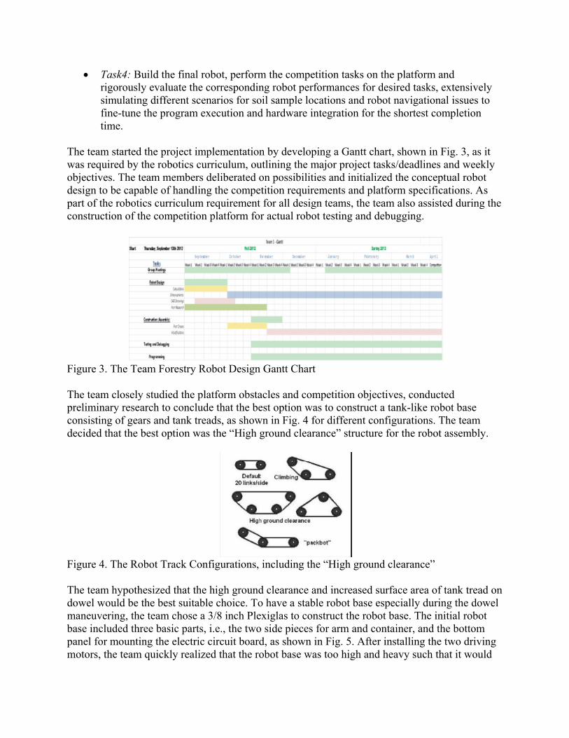
The team started the project implementation by developing a Gantt chart, shown in Fig. 3, as it was required by the robotics curriculum, outlining the major project tasks/deadlines and weekly objectives. The team members deliberated on possibilities and initialized the conceptual robot design to be capable of handling the competition requirements and platform specifications. As part of the robotics curriculum requirement for all design teams, the team also assisted during the construction of the competition platform for actual robot testing and debugging.
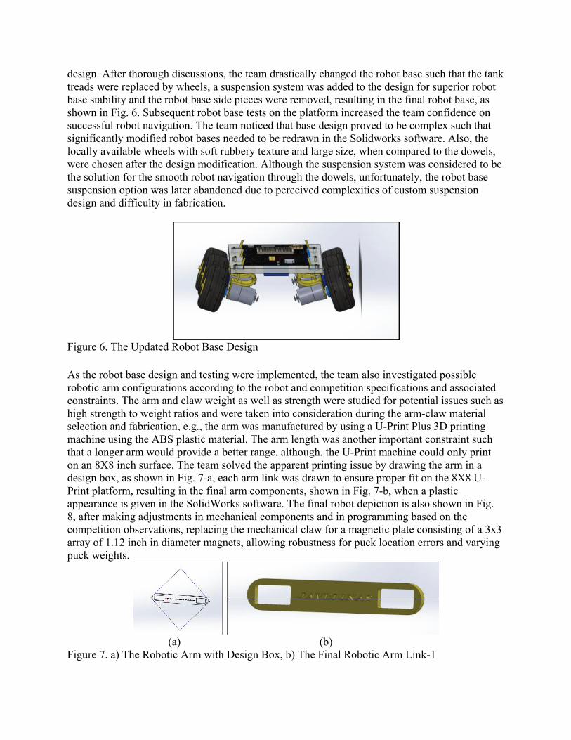
Figure 3. The Team Forestry Robot Design Gantt Chart The team closely studied the platform obstacles and competition objectives, conducted preliminary research to conclude that the best option was to construct a tank-like robot base consisting of gears and tank treads, as shown in Fig. 4 for different configurations. The team decided that the best option was the “High ground clearance” structure for the robot assembly.
Figure 4. The Robot Track Configurations, including the “High ground clearance”
The team hypothesized that the high ground clearance and increased surface area of tank tread on dowel would be the best suitable choice. To have a stable robot base especially during the dowel maneuvering, the team chose a 3/8 inch Plexiglas to construct the robot base. The initial robot base included three basic parts, i.e., the two side pieces for arm and container, and the bottom panel for mounting the electric circuit board, as shown in Fig. 5. After installing the two driving motors, the team quickly realized that the robot base was too high and heavy such that it would

be possible to tip over when attempting to crawl over a dowel on the platform. After the platform test failures, the team decided to increase the portion of the track that was in contact with the platform to prevent a robot tip over. The team also concluded that the robot base weight was an issue during the potential tip over and excessive strain for the drive motors, and addressed the concern by utilizing a 3/16 inch Plexiglas. The second version of the initial robot design with a lower center of gravity was drawn, as shown in Fig. 5.
Figure 5. Preliminary Robot Design
The robot base depiction in Fig. 5 was constructed using the two drive motors and two batteries. During the platform tests, the team observed many issues with the robot base, e.g., the robot base was not successful to climb over a dowel and the clearance between the robot base sides and the tracks showed some problems. Also, different track options were tested to determine whether a tank upgrade kit would give the required robot base height that was needed to climb a dowel. It was observed during the platform tests that the rubber “flappers” on the tracks seemed to be too flimsy to complete the task and started folding under the weight of the robot and the back idler pulley wobbling needed attention. The team became concerned about the wobbling that could cause the tank track to turn such that the robot base traction and torque to the gear could be lost. Thus, the team considered all potentials to address the aforementioned issues and decided the actions, listed as:
• Four tank tread upgrade kits were purchased to change all current hard plastic tread links to rubberized links,
• The width of the robot base was reduced by cutting the panel, • The motor mounts were machine slotted to allow moving the gear components outward
for larger clearance, • All screw holes were drilled to ensure flush mounting of the screw heads, • Two additional motors and associated mounts were purchased and subsequently installed
to the robot base to eliminate low torque issues and undesired variations in the idler wheels,
• The robot base sides were modified to fit the additional two motors, • The gear hubs were filled with the JB Weld and allowed to cure. Holes were drilled and
tapped through the gear hub and the JB Weld to ensure the set screws secure. The team implemented the changes in about a week to test the robot base on the platform while also starting to proceed with the robot arm design and construction. However, the modified robot base tests indicated a failure to climb a dowel, implying a need to further improve the robot base
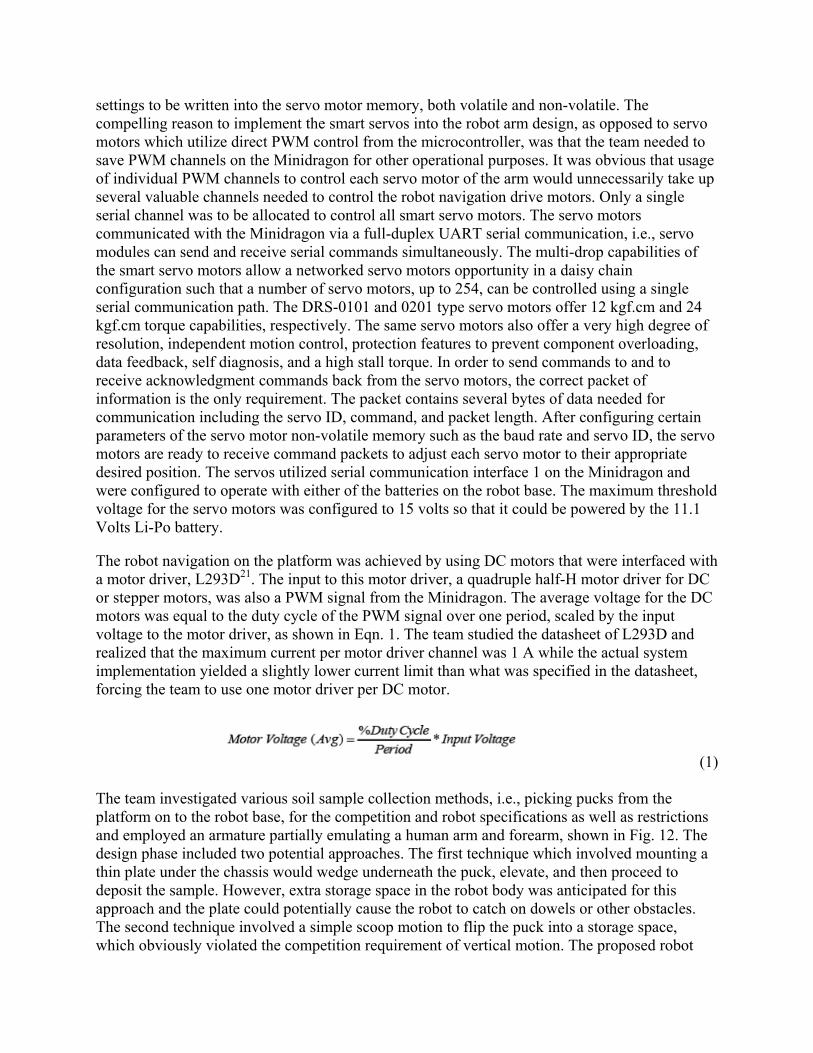
design. After thorough discussions, the team drastically changed the robot base such that the tank treads were replaced by wheels, a suspension system was added to the design for superior robot base stability and the robot base side pieces were removed, resulting in the final robot base, as shown in Fig. 6. Subsequent robot base tests on the platform increased the team confidence on successful robot navigation. The team noticed that base design proved to be complex such that significantly modified robot bases needed to be redrawn in the Solidworks software. Also, the locally available wheels with soft rubbery texture and large size, when compared to the dowels, were chosen after the design modification. Although the suspension system was considered to be the solution for the smooth robot navigation through the dowels, unfortunately, the robot base suspension option was later abandoned due to perceived complexities of custom suspension design and difficulty in fabrication.
Figure 6. The Updated Robot Base Design
As the robot base design and testing were implemented, the team also investigated possible robotic arm configurations according to the robot and competition specifications and associated constraints. The arm and claw weight as well as strength were studied for potential issues such as high strength to weight ratios and were taken into consideration during the arm-claw material selection and fabrication, e.g., the arm was manufactured by using a U-Print Plus 3D printing machine using the ABS plastic material. The arm length was another important constraint such that a longer arm would provide a better range, although, the U-Print machine could only print on an 8X8 inch surface. The team solved the apparent printing issue by drawing the arm in a design box, as shown in Fig. 7-a, each arm link was drawn to ensure proper fit on the 8X8 U-Print platform, resulting in the final arm components, shown in Fig. 7-b, when a plastic appearance is given in the SolidWorks software. The final robot depiction is also shown in Fig. 8, after making adjustments in mechanical components and in programming based on the competition observations, replacing the mechanical claw for a magnetic plate consisting of a 3x3 array of 1.12 inch in diameter magnets, allowing robustness for puck location errors and varying puck weights.
(a) (b)
Figure 7. a) The Robotic Arm with Design Box, b) The Final Robotic Arm Link-1

Figure 8. The Final Robot Design
The team identified all potential electrical components, discussed their advantages and disadvantages for the competition and studied their manuals for proper operations. The team decided to use the Dragon12_Plus218 (Minidragon), shown in Fig. 9, for its solderless breadboard, microSD memory slot, many interface options and board support for many Arduino shields. The team noticed that it was important to check the reference voltage for analog to digital conversion when calculating the voltage received from the Minidragon and that the reference voltage of the Minidragon could be measured from VRH, pin-84, on the board. Although the reference voltage varies for different boards, it was expected to be 5 volts and VRH was 4.9 volts in this design.
Figure 9. The Minidragon Microcontroller18
Figure 10. The GP2D12 Infrared Range Sensor19

When the GP2D12/GP2Y0A02/GP2D12019 infrared range sensor (range sensor), shown in Fig. 10, receives its power from one of the parallel ports on the Minidragon, it was also important to measure the voltage that was supplied from the Minidragon that varies for each board with a nominal value of 5 volts. The team realized that the Minidragon supplied about 4.8 volts. The team used a different variable power source to obtain a constant 5 volts. It should be noted that this small difference in supply voltage plays an important role when the range sensor is read since the range sensor output depends on its input voltage. Also, the different power supply and Minidragon grounds must be connected together for the same reference potential. In addition, when the range sensor was interfaced with the Minidragon, the vertical mount of the range sensor yielded the most accurate results while the horizontally mounted range sensor generated skewed distance data. Also, during the range sensor data acquisition, it was essential to slow the ATD conversion clock speed close to 500 kHz. The length of the second phase sample time was increased to eight ATD clock conversion periods, allowing the ATD converter to obtain a more accurate measurement on the range sensor output. Since the change in voltage on the output of both range sensors can be represented with an exponential decay function as the distance from the sensor increases, the change in output voltage becomes smaller, leading to lower distance measurement accuracy as the distance from the range sensor increases. Multiple piece-wise equations were constructed to represent the output of the range sensor exponential output decays accurately for close and far distances. The team obtained range sensor measurements with two centimeter increments, i.e., sensors having an accuracy of ±2cm, leading to fairly accurate equations. The range sensor measurement accuracy can be increased by reducing the range increment amount. The team tested the range sensor and the actual sensor data was used during the program development.
(a) (b)
Figure 11. The HerkuleX DRS-0101 Model Smart Servo Motor20 a) Front View, b) Range of Servo Operation The team utilized the HerkuleX DRS-0101 smart servo motors20 for the robotic arm and claw manipulations due to their torque capabilities for reasonable price ranges within the project cost management objectives. The servo motors were operated by using a Pulse-Width-Modulation (PWM) signal from the Minidragon PWM channel. The servo motors operated using a signal frequency of 50 Hz and a pulse width ranging from 1.0 ms to 2.0 ms. Each servo motor contains a controller that drives the logic of forward and reverse operations. The forward servo motor direction is achieved by adjusting the pulse-width to greater than 1.5 ms, otherwise, the servo motor rotates in reverse direction, allowing precise and accurate robot arm control as well as the robot claw opening and closing operations. The smart servo motors allow for programmable
settings to be written into the servo motor memory, both volatile and non-volatile. The compelling reason to implement the smart servos into the robot arm design, as opposed to servo motors which utilize direct PWM control from the microcontroller, was that the team needed to save PWM channels on the Minidragon for other operational purposes. It was obvious that usage of individual PWM channels to control each servo motor of the arm would unnecessarily take up several valuable channels needed to control the robot navigation drive motors. Only a single serial channel was to be allocated to control all smart servo motors. The servo motors communicated with the Minidragon via a full-duplex UART serial communication, i.e., servo modules can send and receive serial commands simultaneously. The multi-drop capabilities of the smart servo motors allow a networked servo motors opportunity in a daisy chain configuration such that a number of servo motors, up to 254, can be controlled using a single serial communication path. The DRS-0101 and 0201 type servo motors offer 12 kgf.cm and 24 kgf.cm torque capabilities, respectively. The same servo motors also offer a very high degree of resolution, independent motion control, protection features to prevent component overloading, data feedback, self diagnosis, and a high stall torque. In order to send commands to and to receive acknowledgment commands back from the servo motors, the correct packet of information is the only requirement. The packet contains several bytes of data needed for communication including the servo ID, command, and packet length. After configuring certain parameters of the servo motor non-volatile memory such as the baud rate and servo ID, the servo motors are ready to receive command packets to adjust each servo motor to their appropriate desired position. The servos utilized serial communication interface 1 on the Minidragon and were configured to operate with either of the batteries on the robot base. The maximum threshold voltage for the servo motors was configured to 15 volts so that it could be powered by the 11.1 Volts Li-Po battery. The robot navigation on the platform was achieved by using DC motors that were interfaced with a motor driver, L293D21. The input to this motor driver, a quadruple half-H motor driver for DC or stepper motors, was also a PWM signal from the Minidragon. The average voltage for the DC motors was equal to the duty cycle of the PWM signal over one period, scaled by the input voltage to the motor driver, as shown in Eqn. 1. The team studied the datasheet of L293D and realized that the maximum current per motor driver channel was 1 A while the actual system implementation yielded a slightly lower current limit than what was specified in the datasheet, forcing the team to use one motor driver per DC motor.
(1)
The team investigated various soil sample collection methods, i.e., picking pucks from the platform on to the robot base, for the competition and robot specifications as well as restrictions and employed an armature partially emulating a human arm and forearm, shown in Fig. 12. The design phase included two potential approaches. The first technique which involved mounting a thin plate under the chassis would wedge underneath the puck, elevate, and then proceed to deposit the sample. However, extra storage space in the robot body was anticipated for this approach and the plate could potentially cause the robot to catch on dowels or other obstacles. The second technique involved a simple scoop motion to flip the puck into a storage space, which obviously violated the competition requirement of vertical motion. The proposed robot
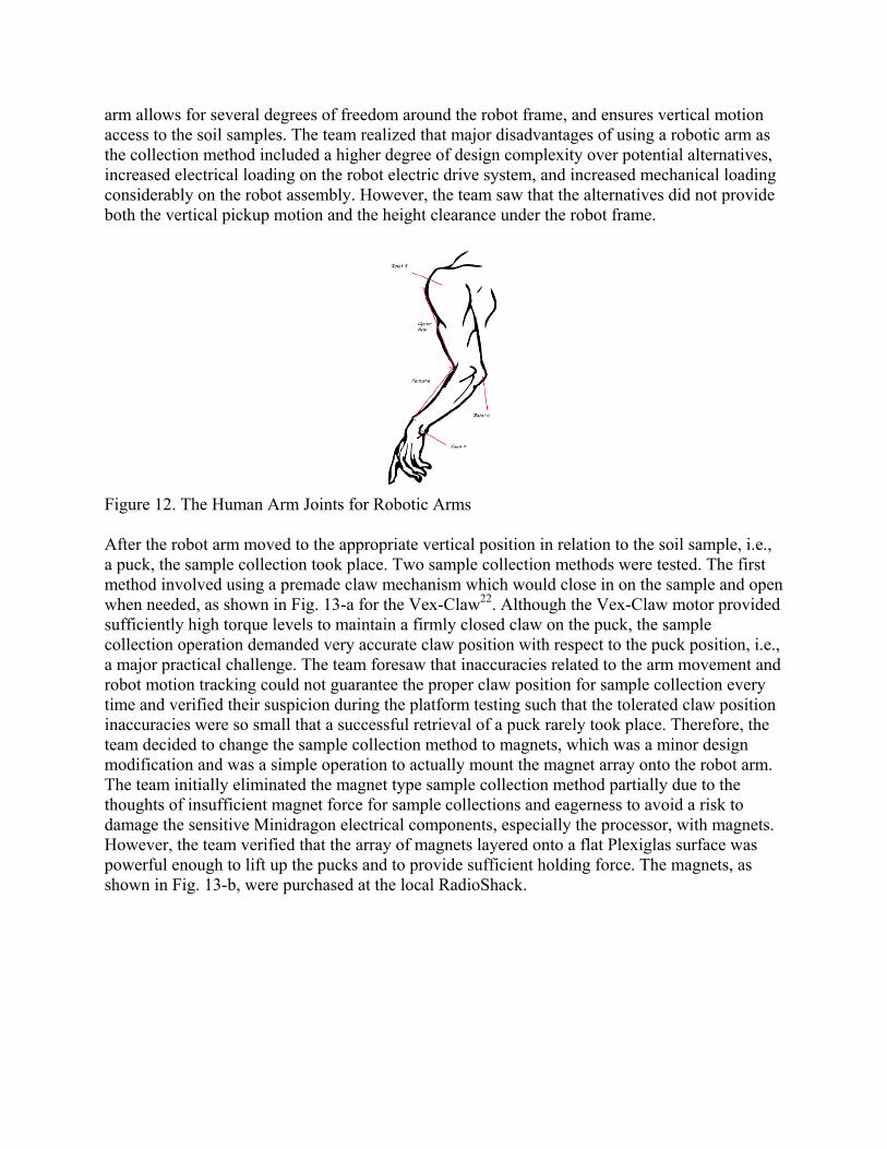
arm allows for several degrees of freedom around the robot frame, and ensures vertical motion access to the soil samples. The team realized that major disadvantages of using a robotic arm as the collection method included a higher degree of design complexity over potential alternatives, increased electrical loading on the robot electric drive system, and increased mechanical loading considerably on the robot assembly. However, the team saw that the alternatives did not provide both the vertical pickup motion and the height clearance under the robot frame.
Figure 12. The Human Arm Joints for Robotic Arms
After the robot arm moved to the appropriate vertical position in relation to the soil sample, i.e., a puck, the sample collection took place. Two sample collection methods were tested. The first method involved using a premade claw mechanism which would close in on the sample and open when needed, as shown in Fig. 13-a for the Vex-Claw22. Although the Vex-Claw motor provided sufficiently high torque levels to maintain a firmly closed claw on the puck, the sample collection operation demanded very accurate claw position with respect to the puck position, i.e., a major practical challenge. The team foresaw that inaccuracies related to the arm movement and robot motion tracking could not guarantee the proper claw position for sample collection every time and verified their suspicion during the platform testing such that the tolerated claw position inaccuracies were so small that a successful retrieval of a puck rarely took place. Therefore, the team decided to change the sample collection method to magnets, which was a minor design modification and was a simple operation to actually mount the magnet array onto the robot arm. The team initially eliminated the magnet type sample collection method partially due to the thoughts of insufficient magnet force for sample collections and eagerness to avoid a risk to damage the sensitive Minidragon electrical components, especially the processor, with magnets. However, the team verified that the array of magnets layered onto a flat Plexiglas surface was powerful enough to lift up the pucks and to provide sufficient holding force. The magnets, as shown in Fig. 13-b, were purchased at the local RadioShack.

(a) (b)
Figure 13. a) The Vex-Claw Structure22, b) The Final Robot Arm Magnet-type Sample Collection
The team members with electrical engineering backgrounds mainly led the Vex robot servo motor testing, developed an assembly program to control the speed and position of the servo motors, used four L293D motor drivers to test the brush-type DC motors to control the speed and direction of the robot by developing an assembly program using an input PWM signal to the motor drivers, developed a program to control the claw of the robot, interfaced the range sensors with the Minidragon to determine the frontal distance of an object from the range sensors. The arm structure refers to the two double-sided links which represent both the upper arm and forearm of a human, as shown in Fig. 12. The joints which represent the shoulder, elbow, and wrists, are controlled by servo motors. The robot arm and human upper limb relationship can also be seen from Fig. 13-b. The servo motor numbers and arm joint numbers are matched, e.g., the servo-1 controls the joint-1 and so on. The team members with mechanical engineering backgrounds mainly led the efforts to design, draw in detail and construct the robotic arm by using the 3D print shop of Mechanical and Industrial Engineering Department, via Solidworks and Flushcut software tools, as shown in Fig. 14-a-b-c. The robot arm links included spaces for mounting the servo motors and mounting the arm onto the rotating servo platform on the robot base.
(a) (b) (c)
Figure 14. a) The First Arm Part, b) The Second Arm Part, c) The Wrist Piece
The final robot arm contained three serial communication smart servo motors along with a single PWM controlled servo for rotation of the arm base, as shown in Fig. 11. The three smart servo motors control the movement of the arm parts, including the wrist movement. The base rotation acts as a sideways rotation for the first joint in the arm, effectively emulating the side-to-side rotation of an elbow. The base rotation is limited to 180 degrees of freedom about the axis of rotation, e.g., the Cartesian z-direction. The robot arm movement starts with the simultaneous

movements of the first two arm parts to affix the arm on the front side of the robot body. The arm then descends, i.e., a vertical drop motion, so that the magnetic sample collection surface is handing parallel to the top of the puck, which was galvanized, and that the magnets come into contact with the top of the puck. When a good connection between the puck and magnet array takes place, the torque loading on the first servo needs to be reduced to prevent overloading and subsequent operation failure. The torque reduction movement was a slight pull backwards towards the robot, thus decreasing the length of the lever arm and subsequently decreasing the amount of torque needed to rotate about the rotational axis. The arm lengths were then pulled back around and the first length is pulled back to a position where the puck was at an appropriate height above the storage vessel for deposit. The base is rotated so that the arm is swung over the storage container for the pucks. The side of the sample makes contact with the side of the storage container and causes the puck to scrape off into the storage container. The arm then rotates and retracts back to its original position. The major component list and associated budget for the robot project is presented in Table 2. Table 2. The Robot Design Project Major Components and Their Prices
Evaluation: The project effectiveness has been illustrated by evaluating the final robot platform performance and the student surveys about the robotics curriculum. The project evaluation indicated the engineering design effectiveness of the robotics curricula such that the participating students were able to design successful autonomous robots for a simulated forest fire environment and the students stated increase in their engineering design and problem solving skills due to the robotics course by marking ‘A Great Deal’ or ‘A Lot’ options at 75% and 91% rates, respectively. Conclusions: The two-course robotics curriculum impact on engineering design and design of a forestry robotics by a student team were presented. The design process and final robot performance were found to be satisfactory according to the robot design and competition guidelines. Acknowledgment: This project was supported by National Science Foundation – Course Curriculum and Laboratory Improvement (CCLI) grant, DUE-0942932. Also, the authors would like to thank the team members, Chris Lara, Josh Ortegon, John Solis, and Eric Wineman, for their dedication and participation of the two-course robotics curriculum as well as the robotics

competition, and Dr. Chung Leung for his assistance during the robot design process. The team final report was partially utilized for the current presentation. Bibliography [1] G. Bekey and J. Yuh, “The Status of Robotics”, IEEE Robotics and Automation Magazine, March 2008. [2] E. Guizzo, “How Goodle’s Self-Driving Car Works”, IEEE Spectrum, October 2011. [3] E. Ackerman, “CMU Develops Autonomous Car Software That’s Provably Safe”, IEEE Spectrum, July 2011. [4] Humanoid Robotics Group, http://www.ai.mit.edu/projects/humanoid-robotics-group/, Last Accessed on December 26, 2011. [5] C. Y. Chen, P. H. Huang, “Review of an Autonomous Humanoid Robot and Its Mechanical Control”, Journal of Vibration and Control, Online, September 2011. [6] E. Guizzo, “These Humanoid Robots Could Kick Your Asimo”, IEEE Spectrum, October 2010. [7] M. Kroh, K. El-Hayek, S. Rosenblatt, B. Chand, P. Escobar, J. Kaouk, S. Chalikonda, “First Human Surgery With a Novel Single-Port Robotic System: Cholesystectomy using the Da-Vinci Single-Site Platform”, Surgical Endoscopy, 25, 11, June 2011, pp. 3566-3573. [8] M. S. Couceiro, J. M. A. Luz, C. M. Fugueiredo, N. M. Fonseca Ferreira, “Modeling and Control of Biologically Inspired Flying Robots”, Robotica, 30, pp. 107-121, April 2012. [9] Google Self-Driving Car Test, http://www.google.com/about/jobs/lifeatgoogle/self-driving-car-test-steve-mahan.html, Last Accessed on January 3, 2014. [10] BigDog, http://www.bostondynamics.com/robot_bigdog.html, Last Accessed on January 3, 2014. [11] DARPA Urban Challenge, http://archive.darpa.mil/grandchallenge/index.asp, Last Accessed on January 3, 2014. [12] S. Kawatsuma, T. Okada, E. Tkeuchi, K. Higashi, S. Tadokoro, “Robotic Control Vehicle for Measuring Radiation in Fukushima Daiichi Nuclear Power Plant”, in 2011 IEEE International Symposium on Safety, Security, and Rescue Robotics, Kyoto, Japan, November 1-5, 2011, pp. 38-43. [13] J. Billingsley, A. Visala, M. Dunn, Robotics in Agriculture and Foresty, Springer Handbook of Robotics, 2008, pp. 1065-1077. [14] T. Hellstrom, O. Ringdahl, “A Software Framework for Agricultural and Forestry Robots”, Industrial Robot: An International Journal, 40(1), pp. 20-26. [15] U.S. Department of Education, National Center on Education Statistics (NCES), Digest of Education Statistics, 2007, Table 275. [16] M. Yilmaz, S. Ozcelik, N. Yilmazer, R. Nekovei, “Design-Oriented Enhanced Robotics Curriculum”, IEEE Transactions on Education, Special Issue on Robotics Education, February 2013, 56 (1), pp. 137-144. [17] M. Yilmaz, N. Yilmazer, S. Ozcelik, R. Nekovei, “A Two-Semester Project-Based Robotics Curriculum,” The 119th ASEE Annual Conference & Exposition (ASEE-2012), June 10-13, 2012, San Antonio, TX, USA. [18] Dragon12-Plus2 Trainer, http://www.evbplus.com/dragon12_plus2_9s12_hcs12/dragon12_plus2_9s12_hcs12.html , Last Accessed on January 2, 2014. [19] SHARP Infrared Sensors, http://www.sharpsma.com/webfm_send/1203, Last Accessed on January 2, 2014. [20] Dongbu Robotics, http://www.dongburobot.com/jsp/cms/view.jsp?code=100788, Last Accessed on January 2, 2014. [21] Texas Instruments, http://www.ti.com/lit/ds/symlink/l293d.pdf, Last Accessed on January 2, 2014. [22] Vex Robotics, Vex-Claw Design, http://content.vexrobotics.com/docs/276-2600-Claw-Assembly.pdf, Last Accessed on January 2, 2014.