foreword - federation of american scientists
TRANSCRIPT

Foreword
The U.S. Army began combat operations in October 2001 with 54 operational Hunter and Shadow unmanned aircraft. Today, the Army has over 4,000 unmanned aircraft systems (UAS) in various sizes and capabilities with still more programmed. After nearly 9 years of continuous combat operations, we have significantly evolved the way we employ UAS in support of our Warfighters. These adaptations are reflected in the tremendous growth of platforms and the expanded capabilities in the current UAS force. While Joint Capabilities Integration and Development System (JCIDS) documents have captured approved requirements and official programs of record have been established, it is now time we pursue a comprehensive strategy or roadmap for establishing future UAS requirements.
The purpose of The US Army UAS Roadmap (2010-2035) is to provide a broad vision for how the Army will develop, organize, and employ UAS across the full spectrum of operations. The major ideas that emerge will provide a common foundation for continued learning and analysis. We will evaluate ideas and challenge assumptions to develop a full range of UAS capabilities. The roadmap will inform warfighting functional concepts, contribute to capabilities-based assessments, and assist in the development of resource informed decisions on new technologies that will be evaluated through comprehensive experimentation and testing. Ultimately, our roadmap will frame an answer to the question, “What UAS capabilities do we need for the Army in the future?”
As described in the Army’s Capstone Concept, to operate effectively under conditions of uncertainty and complexity in an era of persistent conflict, leaders must understand the situation in depth, adapt the actions of their formations to seize and retain the initiative, and be capable of rapid operations over extended distances while sustaining operations over time and across wide areas. Developing and integrating UAS into these formations provide the means to broaden situational awareness as well as improve our ability to see, target, and destroy the enemy. We also expect the UAS of the future to contribute to responsive and continuous sustainment in unsecure, austere environments.
The road map provides the basis for an evolutionary approach to developing and integrating UAS capabilities into our formations. The road map is divided into three time periods: near (2010-2015), mid (2016-2025), and far (2026-2035). The near-term focus addresses gaps in today’s UAS capabilities while emphasizing the rapid integration of existing technologies to meet current demands of the Warfighter on the ground. The mid-term focus is on integrating additional multipurpose UAS into all aspects of Army operations ranging from “Network” support to “Cargo” capable. The more distant future is focused on increasing capability while reducing size, power, and weight requirements. We will review the roadmap every 2 years to remain relevant with operational needs, lessons learned, and emerging technology.
Our first edition UAS Roadmap provides a new direction for future UAS development, and we will adapt it over time to meet the needs of the Soldiers on the ground.
____________________________
GEN Martin E. Dempsey Commanding General, TRADOC
Eyes of the Army U.S. Army Roadmap for UAS 2010-2035
U.S. Army Page i

Page Left Intentionally Blank
Eyes of the Army U.S. Army Roadmap for UAS 2010-2035
U.S. ArmyPage ii
U.S. Army UAS Center of exCellenCe
“eyes of the Army” U. S. Army roadmap for
Unmanned Aircraft Systems2010-2035
Army UAS CoE Staff
U. S. Army UAS Center of Excellence (ATZQ-CDI-C)
Bldg 5000, Lucky Star Street
Fort Rucker, Alabama, 36362-5101
(334) 255-9850
Eyes of the Army U.S. Army Roadmap for UAS 2010-2035
U.S. Army Page iii

Page Left Intentionally Blank
Eyes of the Army U.S. Army Roadmap for UAS 2010-2035
U.S. ArmyPage iv
Table Of Contents1. Executive Summary ............................................................................................................................... 12. Introduction ................................................................................................................................................. 3
2.1 Purpose ..............................................................................................................................................................................32.2 Scope ...................................................................................................................................................................................32.3 Historical Background ..........................................................................................................................................42.4 Vision ...................................................................................................................................................................................72.5 Assumptions .................................................................................................................................................................72.6 UAS Definition .............................................................................................................................................................8
2.6.1 Unmanned Aircraft ..................................................................................................................................82.6.2 Mission Packages ......................................................................................................................................82.6.3 Human Element ..........................................................................................................................................92.6.4 Control Element .........................................................................................................................................92.6.5 Display ........................................................................................................................................................... 102.6.6 Communication Architecture ...................................................................................................... 102.6.7 Life Cycle Logistics ............................................................................................................................... 102.6.8 UAS Integration ...................................................................................................................................... 112.6.9 Tasking, Processing, Exploitation, and Dissemination ........................................... 11
2.7 UAS Groups ................................................................................................................................................................ 122.7.1 Group Capabilities & Limitations ............................................................................................. 12
2.7.1.1 Group 1 ............................................................................................................................................. 122.7.1.2 Group 2 ............................................................................................................................................. 122.7.1.3 Group 3 ............................................................................................................................................. 132.7.1.4 Group 4 ............................................................................................................................................ 132.7.1.5 Group 5 ............................................................................................................................................ 13
2.8 Goals and Objectives ............................................................................................................................................. 133. UAS Operational Environment ................................................................................................. 15
3.1 UAS Operational Environment .................................................................................................................. 153.1.1 Manned-Unmanned Teaming ..................................................................................................... 153.1.2 Command & Control of Army UAS .......................................................................................... 16
3.2 UAS Interoperability with Joint Forces .............................................................................................. 163.2.1 Army UAS Applied to Joint Capability Areas .................................................................. 17
3.3 UAS Interoperability with Other Government Agencies .................................................... 173.4 UAS Interoperability with Coalition Partners............................................................................... 18
4. Threat Environment ........................................................................................................................... 195. Army UAS Employment .................................................................................................................. 21
5.1 UAS Support of Warfighter Functions................................................................................................. 215.2 UAS Echelons ............................................................................................................................................................ 21
5.2.1 Battalion-Level and Below ............................................................................................................. 225.2.2 Brigade-Level ........................................................................................................................................... 23
Eyes of the Army U.S. Army Roadmap for UAS 2010-2035
U.S. Army Page v
5.2.3 Division-Level and Higher .............................................................................................................. 245.3 Operational Vignettes ...................................................................................................................................... 24
5.3.1 Offensive Vignette ................................................................................................................................ 255.3.2 Defensive Vignette ............................................................................................................................... 275.3.3 Civil Support Vignette ....................................................................................................................... 295.3.4 Intelligence Operations Vignette.............................................................................................. 305.3.5 Special Forces Vignette..................................................................................................................... 30
6. Near-term (2010-2015) ................................................................................................................... 326.1 UAS Near-term Capabilities ......................................................................................................................... 346.2 Army UAS Development Considerations .......................................................................................... 34
6.2.1 Doctrine ........................................................................................................................................................ 346.2.2 Organization ............................................................................................................................................ 35
6.2.2.1 Current UAS Organizations .............................................................................................. 356.2.2.1.1 Institutional Army ....................................................................................................... 356.2.2.1.2 Operational Army ....................................................................................................... 35
6.2.3 Training ......................................................................................................................................................... 366.2.3.1 Institutional UAS Training ................................................................................................. 36
6.2.3.1.1 UAS Training Battalion .......................................................................................... 376.2.3.1.2 Professional Military Education ............................................................................ 376.2.3.1.3 Leadership Training .................................................................................................. 37
6.2.3.2 Operational Training ............................................................................................................. 376.2.3.2.1 Individual/Crew Training ...................................................................................... 386.2.3.2.2 Collective Training ..................................................................................................... 38
6.2.3.3 Self-development ..................................................................................................................... 386.2.3.3.1 Knowledge Management ..................................................................................... 386.2.3.3.2 Distance Learning ....................................................................................................... 38
6.2.3.4 Live, Virtual, Constructive, and Gaming Training .......................................... 386.2.4 Materiel ......................................................................................................................................................... 406.2.5 Leadership .................................................................................................................................................. 416.2.6 Personnel ..................................................................................................................................................... 426.2.7 Facilities ........................................................................................................................................................ 426.2.8 Policy ............................................................................................................................................................... 42
6.3 UAS Near-Term Implementation Plan .................................................................................................... 436.3.1 UAS Life Cycle Management ......................................................................................................... 436.3.2 Systems Currently in the Army Inventory ........................................................................... 44
6.3.2.1 RQ-11 Raven B ............................................................................................................................ 446.3.2.2 RQ-7B Shadow ............................................................................................................................ 446.3.2.3 MQ-5 B Hunter ............................................................................................................................ 456.3.2.4 MQ-1C Extended Range Multi-Purpose ................................................................. 45
7. Mid-term (2016-2025) ........................................................................................................................ 497.1 UAS Mid-Term Capabilities .............................................................................................................................. 507.2 Mid-Term Army UAS Development Considerations ..................................................................... 51
Eyes of the Army U.S. Army Roadmap for UAS 2010-2035
U.S. ArmyPage vi

7.2.1 Doctrine ........................................................................................................................................................ 527.2.2 Organization ............................................................................................................................................ 527.2.3 Training ......................................................................................................................................................... 527.2.4 Materiel ......................................................................................................................................................... 537.2.5 Leadership .................................................................................................................................................. 547.2.6 Personnel ..................................................................................................................................................... 547.2.7 Facilities ........................................................................................................................................................ 547.2.8 Policy ............................................................................................................................................................... 55
7.3 UAS Mid-Term Implementation Plan ...................................................................................................... 558. Far-term (2026-2035) ......................................................................................................................... 59
8.1 UAS Far-Term Capabilities ............................................................................................................................... 598.2 Far-term Army UAS Development Considerations....................................................................... 60
8.2.1 Doctrine ........................................................................................................................................................ 618.2.2 Organization ............................................................................................................................................ 618.2.3 Training ......................................................................................................................................................... 628.2.4 Materiel ......................................................................................................................................................... 628.2.5 Leadership .................................................................................................................................................. 638.2.6 Personnel ..................................................................................................................................................... 638.2.7 Facilities ........................................................................................................................................................ 638.2.8 Policy ............................................................................................................................................................... 63
8.3 UAS Far-Term Implementation Plan ........................................................................................................ 649. Army UAS Challenges & Capability Gaps ............................................................................ 66
9.1 U.S. National Airspace System Integration ........................................................................................ 669.2 Electromagnetic Spectrum and Bandwidth Management .................................................... 699.3 Protected Communications............................................................................................................................ 699.4 Processing, Exploitation, and Dissemination of Information ............................................. 709.5 Technological Balance between Manned and Unmanned Aircraft Systems ........... 709.6 Synchronization Effort ....................................................................................................................................... 719.7 Commonality and Architecture ................................................................................................................... 719.8 Payload versus Aircraft Weight ................................................................................................................... 71
10. Conclusion ................................................................................................................................................... 72Appendix A: Unmanned Aircraft Systems ................................................................................. 73Appendix B: Unmanned Aircraft Systems Payloads ........................................................... 83
B.1 Sensors Payloads .................................................................................................................................................... 83B.2 Sensor Types ............................................................................................................................................................... 83
B.2.1 Near-Term Capabilities (FY 2010 – 2015) ........................................................................... 88B.2.2 Mid-Term Capabilities (FY 2016 – 2025) .............................................................................. 89B.2.3 Far-Term Capabilities (FY 2026 – 2035) ............................................................................... 90
B.3 Future Sensing Advancements .................................................................................................................... 90B.4 Sensing Challenges ............................................................................................................................................... 91B.5 Communications Relay Payloads .............................................................................................................. 91
Eyes of the Army U.S. Army Roadmap for UAS 2010-2035
U.S. Army Page vii

B.6 Weapons Payloads ................................................................................................................................................ 92B.7 Lethal Effects .............................................................................................................................................................. 92B.8 Non-Lethal Effects ................................................................................................................................................. 92B.9 Sustainment/Cargo Payloads ....................................................................................................................... 92B.10 Capabilities ................................................................................................................................................................. 92
B.10.1 Group 1 .......................................................................................................................................................... 92B.10.2 Group 2 .......................................................................................................................................................... 93B.10.3 Group 3 .......................................................................................................................................................... 93B.10.4 Group 4 ......................................................................................................................................................... 93
Appendix C: Unmanned Aircraft Systems Control Stations ......................................... 95Appendix D: UAS Organizations ......................................................................................................... 97Appendix E: Unmanned Aircraft System Challenges & Gaps ................................... 105
E.1 Unmanned Aircraft System Airspace Integration ...................................................................... 105E.1.1 Overview ................................................................................................................................................... 105E.1.2 Background ............................................................................................................................................ 105
E.1.2.1 Reliability .................................................................................................................................... 106E.1.2.2 Regulation .................................................................................................................................. 106
E.1.2.2.1 Air Traffic Operations ............................................................................................ 106E.1.2.2.2 Airworthiness Certification .............................................................................. 109E.1.2.2.3 Crew Qualifications ................................................................................................ 110
E.1.2.3 “Sense and Avoid” Principle ......................................................................................... 111E.1.3 Command, Control, Communications ............................................................................... 113
E.1.3.1 Data Link Security ................................................................................................................ 113E.1.3.2 Redundant/Independent Navigation .................................................................... 113E.1.3.3 Autonomy .................................................................................................................................... 113E.1.3.4 Lost Link........................................................................................................................................ 114
E.1.4 Future Environment ........................................................................................................................ 115E.1.5 Army Organizations with Roles in UAS Airspace Integration .......................... 115
E.2 Defensive Measures .........................................................................................................................................115E.3 Deployability .........................................................................................................................................................115
Appendix F: Unmanned Aircraft Systems Stakeholders ..........................................117Appendix G: Acronym List ...................................................................................................................119Appendix H: References ........................................................................................................................125
Eyes of the Army U.S. Army Roadmap for UAS 2010-2035
U.S. ArmyPage viii

List of FiguresFigure 2-1 UAS Training Throughout FY 03-12 ............................................................................................................ 5
Figure 2-2 UAS Supporting the Warfighter ..................................................................................................................... 6
Figure 2-3 UAS Components ....................................................................................................................................................... 8
Figure 2-4 UAS Control Element .............................................................................................................................................. 9
Figure 2-5 Ground Control Station ..................................................................................................................................... 10
Figure 3-1 Manned-Unmanned Teaming ...................................................................................................................... 15
Figure 5-1 Risk vs. Time by Echelon .................................................................................................................................... 22
Figure 5-2 Raven Operations and Missions ................................................................................................................. 23
Figure 5-3 Offensive Operations .......................................................................................................................................... 24
Figure 5-4 Offensive Operations .......................................................................................................................................... 25
Figure 5-5 Offensive Operations .......................................................................................................................................... 26
Figure 5-6 Offensive Operations .......................................................................................................................................... 26
Figure 5-7 Defensive Operations ......................................................................................................................................... 27
Figure 5-8 Defensive Operations ......................................................................................................................................... 28
Figure 5-9 Civil Support Operations .................................................................................................................................. 29
Figure 5-10 Civil Support Operations .............................................................................................................................. 30
Figure 5-11 Intelligence Operations ................................................................................................................................. .31
Figure 5-12 SOF Operations ..................................................................................................................................................... 31
Figure 6-1 Army UAS Capability Timeline ..................................................................................................................... 32
Figure 6-2 Near-Term Manned-Unmanned Roles Transition ......................................................................... 33
Figure 6-3 UAS Training Environment ............................................................................................................................. 36
Figure 6-4 UAS Training Enablers ........................................................................................................................................ 39
Figure 6-5 Digital Data Link ..................................................................................................................................................... 40
Figure 6-6 Fort Campbell UAS Facility ............................................................................................................................. 43
Figure 6-7 Raven .............................................................................................................................................................................. 44
Figure 6-8 Shadow ........................................................................................................................................................................... 44
Figure 6-9 Hunter ............................................................................................................................................................................. 45
Figure 6-10 ERMP ............................................................................................................................................................................. 46
Eyes of the Army U.S. Army Roadmap for UAS 2010-2035
U.S. Army Page ix

Figure 6-11 UAS Near-Term Implementation ............................................................................................................. 47
Figure 7-1 Mid-Term Manned-Unmanned Roles Transition ............................................................................ 50
Figure 7-2 Linking the Battlefield ........................................................................................................................................ 51
Figure 7-3 UAS Simulation Environment ....................................................................................................................... 52
Figure 7-4 UAS Mid-Term Implementation ................................................................................................................... 56
Figure 7-5 UAS Mid-Term Sustainment/Cargo Vignette..................................................................................... 57
Figure 7-6 UAS Nano Vignette ................................................................................................................................................ 58
Figure 8-1 Far-Term Manned-Unmanned Roles Transition ............................................................................. 60
Figure 8-2 UAS Far-Term Implementation .................................................................................................................... 64
Figure 8-3 UAS Nano SWARM Vignette ........................................................................................................................... 65
Figure 9-1 GBSAA Operational Concept (OV-1) ........................................................................................................ 67
Figure 9-2 UAS Synchronization Effort ............................................................................................................................ 71
Figure A-1 Raven RQ-11B ........................................................................................................................................................... 73
Figure A-2 SUAS PIP System Description ........................................................................................................................ 74
Figure A-3 gMAV SUAS ................................................................................................................................................................. 75
Figure A-4 Shadow-200 FQ-7B ............................................................................................................................................... 76
Figure A-5 Hunter MQ-5B ........................................................................................................................................................... 77
Figure A-6 Deployed Preproduction ER/MP Assets ................................................................................................ 78
Figure A-7 ER/MP MQ-1C ............................................................................................................................................................ 79
Figure A-8 XM156 Class 1 ........................................................................................................................................................... 80
Figure A-9 OSRVT Common Systems Integration ................................................................................................... 81
Figure D-1 UAS Organizations ............................................................................................................................................... 97
Figure D-2 MQ-1C ERMP Fielding Schedule ................................................................................................................. 98
Figure D-3 Shadow TUAS PLT .................................................................................................................................................. 99
Figure D-4 Hunter Aerial Reconnaissance Company .......................................................................................100
Figure D-5 IBCT SUAS Distribution & Positions ......................................................................................................101
Figure D-6 HBCT SUAS Distribution & Positions ...................................................................................................102
Figure D-7 SBCT SUAS Distribution & Positions ....................................................................................................103
Figure D-8 ACR SUAS Distribution & Positions .......................................................................................................104
Figure E-1 NAS UAS Access Capability Gaps .............................................................................................................106
Eyes of the Army U.S. Army Roadmap for UAS 2010-2035
U.S. ArmyPage x

Figure E-2 Army UAS Operating Altitudes .................................................................................................................107
Figure E-3 Worldwide Joint UAS Usage ........................................................................................................................108
Figure E-4 Levels of Airworthiness ...................................................................................................................................110
Figure F-1 Army UAS Stakeholders ..................................................................................................................................117
List of TablesTable 2-1 Levels of Interoperability ................................................................................................................................... 11
Table 2-2 UAS Current Systems .............................................................................................................................................. 12
Table B-1 Specific sensor payload characteristics .......................................................................................... 85-87
Eyes of the Army U.S. Army Roadmap for UAS 2010-2035
U.S. Army Page xi
Page Left Intentionally Blank
Eyes of the Army U.S. Army Roadmap for UAS 2010-2035
U.S. ArmyPage xii
Eyes of the Army U.S. Army Roadmap for UAS 2010-2035
U.S. Army Page 1
unmanned aerial vehicle (UAV) successfully flew over 300 combat missions during Operations Desert Shield/Storm. Operational needs and lessons learned from the Global War on Terror (GWOT) prompted the Army to increase the number and capabilities of UAS. Currently, there are more than 328 Army UAS deployed in theater, which have flown in excess of one million hours in support of combat operations. To keep pace with the prolific UAS growth, the Army will train more than 2,100 UAS operators, maintainers, and leaders in fiscal year (FY) 2012, which is an 800 percent increased compared to the FY 2003 training quota.
Army UAS are the “Eyes of the Army” and support information dominance by providing the capability to quickly collect, process, and disseminate relevant information to reduce the sensor-to-shooter timeline. In addition, UAS support tactical echelons in Army and Joint operations and provide the Warfighter a tactical advantage through near real-time situational awareness, multi-role capabilities on demand (including communications, reconnaissance, armed response, and sustainment applications), and the ability to dynamically retask. A UAS is comprised of an unmanned aircraft (UA), payload, human operator, control element, display, communication architecture, life cycle logistics, and the supported Soldier. The idea that UAS are “unmanned” is a misnomer because trained and professional Soldiers operate and maintain Army UAS. Therefore, the centerpiece of this strategy focuses on all aspects of UAS capability in support of the Soldiers. The overarching objective is to synchronize UAS equipment with the human and networking elements. Commonality and an open architecture systems approach are the two key fundamentals of the Army’s future UAS strategy.
The Army currently employs UAS across all echelons as dedicated or organic support to tactical, operational, and strategic operations. The typical Army UAS echelons are:
• Battalion-level and lower: close-range (less than 25 kilometers), short-duration (one to two hours) missions that operate below the coordinating altitude and are thoroughly integrated with ground forces as an organic asset supporting tactical operations.
• Brigade-level: medium-range (less than 125 kilometers), medium-duration (five to 10 hours) missions that integrate with ground forces and other aviation assets.
• Division-level and higher: extended range (200 kilometers or more), long duration (16 hours or more), missions in direct support (DS), or general support (GS) at the tactical or operational level.
1. Executive SummaryThe Unmanned Aircraft System (UAS) Roadmap outlines how the U.S. Army will develop, organize, and employ UAS from 2010 to 2035 across full spectrum operations. The Army UAS Roadmap is nested with the Unmanned Systems (UMS) Initial Capabilities Document (ICD) and capitalizes on UAS capabilities and emerging technologies so that the Warfighter can conduct missions more effectively with less risk. Experiences in Operation Enduring Freedom (OEF) and Operation Iraqi Freedom (OIF) prove that UAS significantly augment mission accomplishment by reducing a Soldier’s workload and their exposure to direct enemy contact. The UAS serve as unique tools for the commander, which broaden battlefield situational awareness and ability to see, target, and destroy the enemy by providing actionable intelligence to the lowest tactical levels. Unmanned platforms are the emerging lethal and non-lethal weapons of choice that will continue to transform how the Army prosecutes future operations and ultimately save lives. The eventual employment of sustainment/cargo UAS will ensure responsive and uninterrupted sustainment support ultimately increasing freedom of action and operational reach. The Roadmap, although not directive in nature, is a living document that factually and conceptually benchmarks the Army’s UAS strategy for the next 25 years and provides a common vision for all organizations responsible for synchronizing this transformation.
In 1915, Nicola Tesla introduced the concept of unmanned flight in his dissertation that described an armed, pilotless-aircraft designed to defend the United States. The Army’s UAS program came to fruition in 1991 when the Pioneer
“We can send a UAS to look down alleys, around buildings, in backyards, or on a roof to see what’s up there, dramatically increasing Soldier protection and preserving the force – a vital force multiplier in this era of persistent conflict.”Major General James O. Barclay, III, Commanding General of the United States Army Aviation Center of Excellence (USAACE) and Fort Rucker, AL

Eyes of the Army U.S. Army Roadmap for UAS 2010-2035
U.S. ArmyPage 2
avoid (SAA) capability, and integrate into the national airspace (NAS). Medical evacuation (MEDEVAC) UAS and Nano technology with swarming capability are likely to mature. Sustainment/cargo UAS will continue to lever-age advanced technologies that may offer the potential for giant leaps in onboard computational and storage ca-pabilities, as well, as reduction of size and weight of the UAS platform. Sustainment/cargo UAS are fielded Army wide. Multi-purpose and multi-role UAS support the full range of military operations where operators control multiple UAS from a common control system. UAS are fully integrated into unmanned ground systems as an unmanned systems team providing new UMS synergy and capabilities to the Commander.
The unprecedented UAS maturation rate is enabling combat commanders to employ a variety of UAS across the depth and breadth of the battlefield. While UAS will continue to take on increasingly diverse roles to support the Soldier, the “Eyes of the Army” mission will never subside. Throughout the next 25-years, the Army will further transform based upon lessons learned, operational needs, and emerging technologies. The Army’s UAS Roadmap provides a comprehensive overview of current UAS capabilities through future employment potential. Support to current operations in both Iraq and Afghanistan is paramount while the Army maintains its focus on future, dissimilar battlefields and diverse areas of operation. The UAS are a proven combat multiplier because they increase situational awareness, reduce workloads, and minimize the risk to the forward deployed Soldier. The Army must continue to leverage existing and emerging technologies to capitalize from UAS potential. The fielding of technologically advanced unmanned systems is expected to deliver savings in force structure and costs over time. The Roadmap is the Army’s first synchronized effort to outline UAS strategies for the next quarter-century by focusing on unmanned aircraft, emerging technologies, system interoperability, commonality, and most importantly continued support to the Warfighter.
The eight takeaway themes of the Army’s UAS Roadmap are:
• Soldiers are the backbone of the Army’s UAS strategy.
• The Army synchronizes the human, networking, and equipment elements.
• The Army uses a “commonality” and an “open architecture systems” approach as the two fundamental foundations of the UAS strategy.
• The Army’s UAS strategy provides dynamically retaskable assets to ground commanders.
The Roadmap spans a 25-year period and serves as a conceptual document that covers three distinct periods: Near-term (2010-2015), Mid-term (2016-2025), and Far-term (2026-2035). Each time period is further broken into subsections, which outline the evolution of capabilities, developmental considerations (using doctrine, organization, training, materiel, leadership, personnel, facilities – policy [DOTMLPF-P]), and the expected implementation plan. Descriptions in the near-term are more substantial and based upon current technologies, funding, and programs of record, whereas the far-term is conceptual and based upon expected capabilities.
• Near-Term. Continued rapid integration of UAS into tactical organizations meets the Warfighter’s current combat requirements. Intelligence, surveillance, and reconnaissance is the dominant UAS capability require-ment. Base budgets include UAS procurement and sustainment, which demonstrate the Army’s full com-mitment to enduring capability requirements. Network capability limits information distribution. Systems in the near-term include the Extended Range Multi Purpose (ERMP), Hunter, Shadow®, and Raven UAS. Both com-monality and interoperability between systems and controllers are limited. A careful exploration of technolo-gies to support the development and employment of a sustainment/cargo UAS is also required during this period.
• Mid-Term. The Army fully integrates UAS. Technologi-cal advances increase UAS autonomy and support rapid and fluid operations. UAS resolution (targeting effects, collateral damage) and the net-centric force capability increase. Optionally piloted vehicles (OPV) and lighter than air (LTA) vehicles emerge to bridge the gap between manned and unmanned capabilities. Operators ma-nipulate multiple platforms with a universal system and disseminate the resulting information across multiple echelons. Multiple users also will manipulate sensor con-trol from distributed sites. ERMP UAS are fully fielded and the Army begins fielding a sustainment/cargo UAS at the tactical and operational levels. Start unmanned systems teaming with unmanned ground vehicles and unattend-ed sensors through common interoperability standards.
• Far-Term. Drastic commonality and capability im-provements of both manned and unmanned systems characterize the far-term. Technological advancements increase endurance and carrying capacity while size, weight, and power (SWaP) requirements decrease. The Army leverages advanced vertical takeoff and landing technology to provide a point-to-point capability and overall UAS autonomy improves. UAS are capable of operating in all weather conditions, possess sense and
Eyes of the Army U.S. Army Roadmap for UAS 2010-2035
U.S. Army Page 3
number one combatant commander (COCOM) priority for unmanned systems. While the demand for full motion video (FMV) remains high, there is an increasing demand for wide-area search and multi-intelligence capability. Processing, exploitation, and dissemination (PED) remains a key area highlighting the need for interoperability. • Chemical, Biological, Radiological, Nuclear,
and High Yield Explosives Reconnaissance. The ability to find chemical, biological, radiological, nu-clear, high yield explosives (CBRNE) materiel or hazards and to survey the affected areas, while minimizing the exposure of personnel to these agents, is a crucial effort inside and outside U.S borders.
• Counter-Explosive Hazards. Explosive hazards are the number one cause of coalition casualties in OIF/OEF. Improving the military’s ability to find, mark, and destroy explosive hazards and land mines is a significant effort.
Security. Security operations preserve friendly force combat power and freedom of maneuver, while providing information about the threat and terrain. UAS support security operations by providing information regarding the threat; and deny this threat the ability to observe and execute direct fire engagements on the protected force.
Attack.• Close Combat. The UAS support close combat by
operating as a part of the combined arms team when conducting decisive, integrated, air-ground operations, to close with and destroy the enemy through fire and maneuver. The air/ground scheme of maneuver fully integrates the weaponized UAS.
• Interdiction Attack. The UAS and attack helicopters, when coupled with Army/Joint fires, provide the Warfighter the ability to extend the battle to the maximum range of organic/supporting sensors. The UAS electronic attack (EA) capability includes attack on personnel, facilities, or equipment with the intent of degrading, neutralizing, or destroying enemy combat capability.
• Strike. Strike missions, which are similar to an interdiction attack in UAS employment, occur when in DS to the Fires brigade. A weaponized UAS has the capability to destroy a high value target (HVT) using direct or indirect fires. This UAS can conduct high risk and high payoff attack/strike operations with minimal exposure of manned systems. The weaponized UAS
• The Army’s UAS provide actionable intelligence to the lowest tactical level.
• The Army’s UAS strategy shortens the “sensor-to-shooter” timeline.
• The Army’s UAS support full spectrum operations
• Allow commanders to employ a variety of capabilities
2. Introduction
2.1 Purpose
This Roadmap outlines how the U.S. Army will develop, organize, and employ UAS from 2010 to 2035 across the full spectrum operations. The Army will capitalize on UAS capabilities and implement emerging technologies so the Warfighter can conduct missions more effectively with reduced risk. The Army’s experiences in OIF and OEF prove UAS significantly augment mission accomplishment by reducing the Soldier workload and exposure to direct enemy contact. This Roadmap is a living document that factually and conceptually benchmarks the Army’s UAS strategy for the next 25 years and provides a common Army vision for all associated organizations. The Army will update the Roadmap to reflect our progress and improved understanding every two years, but its long-term value is the synchronization it achieves among diverse stakeholders.
2.2 Scope
The scope of this Roadmap is limited to U.S. Army UAS. It implements the Army and Joint UAS vision across a 25-year period (2010-2035). Soldiers employ UAS across the full spectrum of conflict. This Roadmap describes the strategy for Army UAS that focuses on delivery of warfighting capability. It is nested under FY 2009-2034 Department of Defense (DoD) Unmanned Systems Integrated Roadmap and is intended to complement Army ISR strategies, Army Global Network Enterprise Construct strategic vision as well as other transformational capabilities in all of the warfighter functions, such as an emerging sustainment concept of support for unmanned ground and aerial resupply. Its overarching goal is to focus Army investments in unmanned systems and technologies to meet the prioritized capability needs of the Warfighter that include the following missions.
Reconnaissance and Surveillance. This remains the
Eyes of the Army U.S. Army Roadmap for UAS 2010-2035
U.S. ArmyPage 4
Mid-term investments focus on requirements and capabilities outlined in the Extended Planning Period (EPP). The far-term explores conceptual capabilities from emerging technologies. This framework supports the realities of rigorous time and fiscal constraints as they apply to UAS fielding and integration. It presents UAS as a fully integrated force multiplier for the Army. The Roadmap outlines DOTMLPF-P lessons learned, while balancing future requirements and provides a foundation for a formalized and detailed Army UAS strategy. The concepts and visions described are neither directive nor intended to reflect resourcing priorities or decisions. Instead, the ideas solidify a starting point for future Army UAS integration and establish an enduring review of UAS capabilities.
2.3 Historical Background
As stated earlier, the genesis of unmanned flight began in 1915 when Tesla believed an armed, pilotless-aircraft could be used to defend the United States. In 1919, Elmer Sperry, the creator of gyroscope and autopilot technology, used a pilotless aircraft to sink a captured German battleship as part of a demonstration of gyroscope-guided technology.
As far back as 1953, Fort Huachuca, Arizona, was the Army’s test bed and fielding location for UAS, formally known as remotely piloted vehicles and unmanned aerial vehicles (UAV). In 1979, the Army started its first major UAS acquisition effort with the Aquila program. During operational testing in 1987, the Aquila program successfully met mission requirements in only seven of 105 flights. In 1985, the DoD procured the Pioneer, its first operational UAV system, which flew over 300 combat missions during Operation Desert Shield/Storm in 1991 hunting for Scud missiles and high value targets for coalition commanders.
The Army’s Intelligence Center of Excellence (CoE) at Fort Huachuca retained UAS authority until those responsibilities transferred to the U.S. Army’s Aviation CoE (USAACE) at Fort Rucker, Alabama, on 19 June 2003. USAACE’s UAS Training Battalion (UASTB) conducts all tactical UAS (TUAS) training, which includes the Shadow, Hunter, and ERMP at Fort Huachuca. The Army’s Maneuver Center of Excellence at Fort Benning, Georgia, conducts all small UAS (SUAS) training,
penetrates threat airspace to attack an area or known high payoff target. In strike missions, the Fires brigade employs precision Army fires, reinforced by Joint fires, and complemented by attack aviation (including ERMP). Strike missions require a continuous capability to immediately locate, strike, and conduct physical damage assessments of commanders’ time sensitive targets throughout the area of operation (AO).
• Target Identification and Designation. The ability to positively identify and precisely locate military targets in real-time is a shortfall with current U.S. Army UAS. Reducing latency and increasing reliability of precision guided weapons is required.
Command, Control, and Communications Support. Command, control, and communications (C3) support provides commanders with the ability to broaden the communication network throughout the extended and possibly austere AO, thus improving effective command and control. UAS with network extension payloads enable continuous network connectivity among networked weapon systems, sensors, Soldiers, leaders, platforms and command posts (CP) at all echelons; during all phases of combat, while on-the-move (OTM), in complex/urban terrain and in all weather conditions.
Combat Support. Unmanned aircraft systems are ideally suited to support a wide variety of combat support missions, which include military intelligence, engineer, military police, and chemical operations as well as combat identification (CID) to distinguish between friend, enemy, neutral, and noncombatant.
Sustainment. Unmanned aircraft systems may provide routine sustainment functions in the delivery of supplies and materials to forward deployed units. In the future, unmanned sustainment aircraft may conduct autonomous supply/retrograde operations as well as extraction of damaged parts for repair. These systems also will be capable of extraction of wounded and enemy prisoners of war. A sustainment/cargo UAS asset could provide responsive and precise transport of small, high value payloads.
The Roadmap concepts are divided into three sections: Near- term: (2010 to 2015), Mid-term: (2016 to 2025), and Far-term: (2026 to 2035). Each section describes UAS capabilities in the context of DOTMLPF-P, lessons learned, tactics, techniques, and procedures (TTP) and emerging employment concepts. Near-term investments enhance current UAS capabilities, set the stage for incremental improvements, and are outlined in Program Objective Memorandum (POM) from FY 2010-2015.
“The difference between science fiction and science is timing” Colonel Christopher B. Carlile, Director, UAS Center of Excellence (CoE), Fort Rucker, AL

Eyes of the Army U.S. Army Roadmap for UAS 2010-2035
U.S. Army Page 5
management
• Coordinate and budget for the development and procurement of unmanned systems
• Develop an implementation plan that assesses progress towards meeting goals established in Section 220 of the National Defense Authorization Act of FY 2001 that by 2010, one-third of the operational Joint deep strike aircraft of the armed forces will be unmanned
Unmanned aircraft systems can provide three critical capabilities for the Army’s current and future force. First, UAS reduce risks to Soldiers in the current fight (e.g., explosive hazard detection and neutralization). Second, UAS reduce the workload on Soldiers by performing routine missions and enable sustained high tempo operations (e.g., routine surveillance of forward operating bases). Third, UAS provide emerging capabilities for extended range or standoff reconnaissance operations.
which includes the Raven. To keep pace with the prolific UAS growth, the Army will train more than 2,100 UAS operators, maintainers, and leaders in FY 2012, which is an 800 percent increased compared to the FY2003 training quota as depicted in Figure 2-1, UAS Training Throughout FY 03-12.
Unmanned aircraft systems successes in combat prompted Congress to pass the FY 2007 (Public Law 109-364) John Warner National Defense Authorization Act, requiring DoD to establish policies that:
• Identify a preference for unmanned systems in acquisitions of new systems
• Address joint development and procurement of unmanned systems and components
• Transition Service unique unmanned systems to joint systems as appropriate
• Establish an organizational structure for effective
Figure 2-1 UAS Training Throughout FY 03-12
Course Description 03 04 05 06 07 08 09 Projections
10 11 12Operator Common Core (15W) 372 380 392 367 587 517 630Shadow Operator (15W) 125 212 291 262 364 313 343 552 447 582Shadow Opr (15W) (Transition) 18 7 34 3 16 20Shadow UAS Repairer-U2 (15J) 51 78 83 75 76 105 359 374 386 220Hunter Operator (15W) 20 24 20 10 15 18 20 15 18Hunter Opr (15W) (Transition) 2 1 3 5 5Hunter UAS Repairer-U3 (15J) 51 27 8 12 2 18 19 20 8 7Hunter External Operator (15W) 2 1 4 2 4 3 2 5 4 4UAS Warrant Officer (150U) 9 5 6 21 42 11 34 22 45 45Instructor Operator (CC) 18 55 121 40 124 132 145 140Instructor Operator (Shadow) 100Instructor Operator (Hunter) 10Instructor Operator (ER/MP) 20Cmdr & Staff Officer Course 114 63 91 90 115 118Warrior Alpha 20 43 52 50 50 50Warrior Alpha (TO and Land) 5 5 5ER/MP Operator (15W) 43 67 55 56ER/MP Opr (15W) (Transition) 32 14 32ER/MP UAS Repairer-U5 (15J) 55 60 80USMC Mission Commander 22 16 16 16
Total 256 350 470 822 1134 1006 1479 2027 1903 2153Annual Increase % *** 137% 134% 175% 138% 89% 147% 137% 94% 113%
Eyes of the Army U.S. Army Roadmap for UAS 2010-2035
U.S. ArmyPage 6
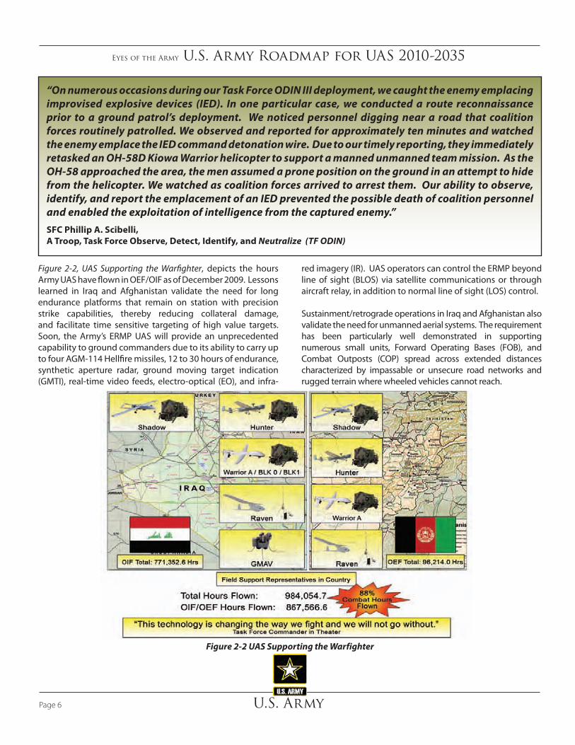
“On numerous occasions during our Task Force ODIN III deployment, we caught the enemy emplacing improvised explosive devices (IED). In one particular case, we conducted a route reconnaissance prior to a ground patrol’s deployment. We noticed personnel digging near a road that coalition forces routinely patrolled. We observed and reported for approximately ten minutes and watched the enemy emplace the IED command detonation wire. Due to our timely reporting, they immediately retasked an OH-58D Kiowa Warrior helicopter to support a manned unmanned team mission. As the OH-58 approached the area, the men assumed a prone position on the ground in an attempt to hide from the helicopter. We watched as coalition forces arrived to arrest them. Our ability to observe, identify, and report the emplacement of an IED prevented the possible death of coalition personnel and enabled the exploitation of intelligence from the captured enemy.”SFC Phillip A. Scibelli, A Troop, Task Force Observe, Detect, Identify, and Neutralize (TF ODIN)
red imagery (IR). UAS operators can control the ERMP beyond line of sight (BLOS) via satellite communications or through aircraft relay, in addition to normal line of sight (LOS) control.
Sustainment/retrograde operations in Iraq and Afghanistan also validate the need for unmanned aerial systems. The requirement has been particularly well demonstrated in supporting numerous small units, Forward Operating Bases (FOB), and Combat Outposts (COP) spread across extended distances characterized by impassable or unsecure road networks and rugged terrain where wheeled vehicles cannot reach.
Figure 2-2 UAS Supporting the Warfighter
Figure 2-2, UAS Supporting the Warfighter, depicts the hours Army UAS have flown in OEF/OIF as of December 2009. Lessons learned in Iraq and Afghanistan validate the need for long endurance platforms that remain on station with precision strike capabilities, thereby reducing collateral damage, and facilitate time sensitive targeting of high value targets. Soon, the Army’s ERMP UAS will provide an unprecedented capability to ground commanders due to its ability to carry up to four AGM-114 Hellfire missiles, 12 to 30 hours of endurance, synthetic aperture radar, ground moving target indication (GMTI), real-time video feeds, electro-optical (EO), and infra-
Eyes of the Army U.S. Army Roadmap for UAS 2010-2035
U.S. Army Page 7
2.5 Assumptions
Assumptions used to develop this Roadmap are:
• Integration of manned and unmanned systems will increase capability across full spectrum operations.
• Industry will deliver the required technologies for combat system development within affordable constraints.
• During peacetime, UAS operations will comply with appropriate national and international flight standards once defined.
• Congressional mandates and lessons learned will continue to validate the need for UAS capabilities within a professional and standardized UAS community.
• Higher levels of autonomy will improve performance while reducing cost, risk, and personnel.
• System advances allow for massive increases in data processing from multiple data sources.
2.4 Vision
The Army’s UAS vision drives the strategy for the development and employment of unmanned systems in three ways. First, operational needs drive the current, developmental, and future UAS capabilities. Second, analysis of required capabilities identifies the performance needed by unmanned systems in the future. Third, the implementation plan synchronizes the DOTMLPF-P efforts to realize a desired capability.
According to the 2009 Army Campaign Plan, Aviation Transformation Annex, the UAS implementation strategy must:
• Bridge the gap between current and future UAS requirements
• Set the conditions for prioritized funding, procurement, distribution, utilization/operation, life-cycle support, and force structure for the Modular Army Forces and the Future Combat Force maneuver and support Brigade Combat Teams (BCT)
• Ensure a synchronized approach to training with a common UAS operator and one system remote video terminal (OSRVT)
Army UAS employed across all tactical echelons supporting Army and Joint operations, provide the Warfighter a disproportionate advantage through near real- time situational awareness, multi-role capabilities on demand (including communications, reconnaissance, and armed response), and system employment from dynamic retasking through autonomous operations.
Army UAS Vision Statement
The Army UAS strategy describes UAS platforms and capabilities within the Army and Joint Team in the traditional aviation combat roles - reconnaissance, surveillance, security, attack, cargo, utility and command and control. The Army envisions an operator capable of controlling all Army UAS platforms, to include multiple platforms, from one common ground control station, disseminating sensor/mission results across multiple echelons via multiple means such as a common remote video transceiver and a robust digital network. As UAS mature, commanders will employ a variety of UAS across the breadth and depth of their AO, with appropriate mission packages and sensors to achieve mission objectives. UAS will support the full range of military operations optimally mixed with manned aviation platforms and team with Army and Joint ground and air combat and support systems.
Eyes of the Army U.S. Army Roadmap for UAS 2010-2035
U.S. ArmyPage 8
2.6.2 Mission Packages
Mission packages are equipment carried on a UAS configured to accomplish a specific mission. Typical payloads include sensors, communications relay, weapons (lethal and non-lethal), and cargo, which may be internal or external to the UA. The current challenges, with respect to payloads are SWaP, accuracy, and resolution. Technological advancements in the mid-and far-term will greatly increase payload performance in support to the Warfighter. Appendix B, UAS Payloads, includes an in-depth discussion of current and future payloads.
Typical mission package categories include:
• Sensor payloads include EO, infrared (IR), synthetic aperture radar (SAR), GMTI, signal intelligence (SIGINT), and electronic attack. Sensor products also include FMV and still frame imagery.
• Communications payloads extend voice and data transmissions via the UAS. Future communication payloads may include communications relay, range extension, and translation capabilities that will allow the
2.6 UAS Definition
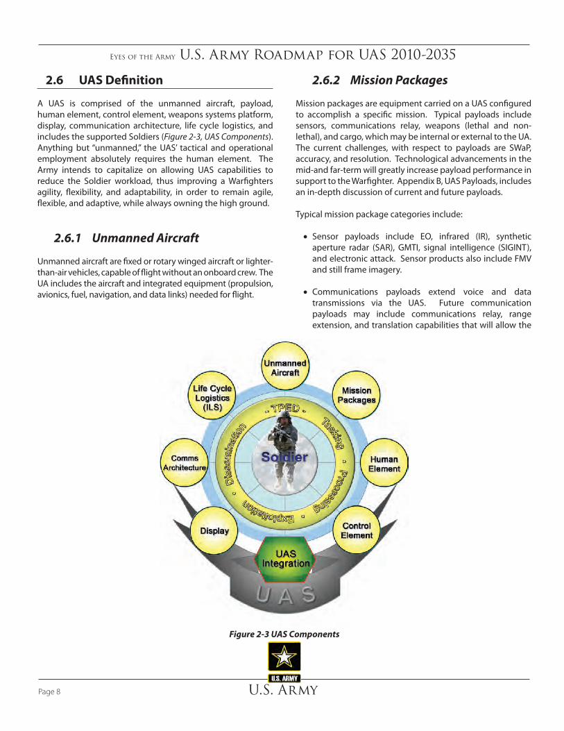
A UAS is comprised of the unmanned aircraft, payload, human element, control element, weapons systems platform, display, communication architecture, life cycle logistics, and includes the supported Soldiers (Figure 2-3, UAS Components). Anything but “unmanned,” the UAS’ tactical and operational employment absolutely requires the human element. The Army intends to capitalize on allowing UAS capabilities to reduce the Soldier workload, thus improving a Warfighters agility, flexibility, and adaptability, in order to remain agile, flexible, and adaptive, while always owning the high ground.
2.6.1 Unmanned Aircraft
Unmanned aircraft are fixed or rotary winged aircraft or lighter-than-air vehicles, capable of flight without an onboard crew. The UA includes the aircraft and integrated equipment (propulsion, avionics, fuel, navigation, and data links) needed for flight.
Figure 2-3 UAS Components

Eyes of the Army U.S. Army Roadmap for UAS 2010-2035
U.S. Army Page 9
tasking, processing, exploitation, and dissemination (TPED), such as adding new sensor capabilities, will affect other warfighting functions.
2.6.4 Control Element
The control element (Figure 2-4), encompasses several mission aspects, such as command and control (C2), mission planning, takeoff and landing, UA control, payload control, weapons control, and communications. For the purposes of clarity in this Roadmap, the control element is located at the GCS depicted in Figure 2-5. The GCS can be a laptop computer, a kit mounted on an Army vehicle/aircraft, or in a larger fixed facility. The UAS GCS are migrating into airborne platforms, enabling flight and navigation control from manned aircraft.
Currently, some UAS require two or more personnel to control both the UA and payload. The Army’s future UAS vision includes an operator who simultaneously manipulates multiple UAS platforms from a single crew station with a universal ground control station (UGCS) and future increments of OSRVT.
Warfighter to communicate between disparate types of radios, data links, and networks.
• Weapon payloads include both lethal (missiles and bombs) and non-lethal EA systems designed to injure, kill, or incapacitate people; damage or destroy property; or otherwise render resources nonfunctional or unavailable.
• Sustainment/cargo UAS may eventually deliver and/or pickup supplies, equipment, and personnel.
2.6.3 Human Element
The human element is crucial to successful UAS employment. The idea that UAS are “unmanned” is a misnomer because the human element is at the core of the overall system. Although UAS operate with varying degrees of autonomy, they all require human interface throughout the mission. Commanders must ensure UAS personnel requirements, limitations, and unit manning are sufficient to accomplish assigned missions. Accounting for personnel requirements associated with
Figure 2-4 UAS Control Element

Eyes of the Army U.S. Army Roadmap for UAS 2010-2035
U.S. ArmyPage 10
2.6.6 Communication Architecture
The communication architecture consists of the hardware and software to exchange data and voice communications between the unmanned system (UMS), control element, and Soldier. UAS data links transmit and receive either by LOS or by BLOS. The UA provides an aerial communications capability to extend the network in support of a specific UAS mission and provides retransmission capability for ground operations. These data links can directly supply the Warfighter with imagery and associated metadata via direct LOS downlink to an OSRVT. Currently, OSRVT reception is limited to LOS only. The Warfighter needs the UAS communication architecture to transmit interoperable data and voice to reduce the sensor to shooter time.
2.6.7 Life Cycle Logistics
Like manned aircraft, UAS require dedicated logistical support, which includes the equipment to deploy, transport, launch, recover, enable communications, and sustain the UAS. Additionally, within the architecture
The physical location of the GCS can be fixed or mobile and is dependent upon the mission and commander’s requirements. All Army GCS operate via LOS and are located and controlled in the AO they support. The Block II OSGCS for ERMP will also allow for satellite control. The Army is incrementally increasing interoperability of OSGCS with common user control station, tactical common data links (TCDL), Standardization Agreement (STANAG) 4586 compliance and other obsolescence upgrades that will provide an open architecture and interoperable universal GCS.
UAS controllers exercise authority over UAS behavior and data at one of five “Levels of Interoperability” (LOI) established in the North Atlantic Treaty Organization (NATO) STANAG 4586. Table 2-1 defines the five LOI.
2.6.5 Display
Displays include the GCS display systems, handheld displays, other remote viewing display systems, and other manned cockpit displays.
Figure 2-5 Ground Control Station

Eyes of the Army U.S. Army Roadmap for UAS 2010-2035
U.S. Army Page 11
2.6.9 Tasking, Processing, Exploitation, and Dissemination
Automated TPED will optimize tasking of multiple assets to meet real-time collection needs while providing a means to analyze a greater portion of the data and imagery collected. Every sensor system must fit into a TPED architecture that ensures pertinent intelligence reaches the appropriate organization for action via the battle command system. Commanders or analyst must possess the ability to collaborate and manage the data and imagery to display a common operational picture (COP) and be able to disseminate down to the lower echelons. The need for dissemination to Joint, Interagency, Intergovernmental, and Multinational (JIIM) partners with system interoperability is especially important. Content (data) storage capacity for forensics must be sufficient and planned. As UAS capabilities and employment evolve
mentioned above, the UAS will provide data to provide system health status necessary to support condition based maintenance (CBM)/reliability centered maintenance and future sustainment concept initiatives. For a small hand-launched system, relatively little support equipment is needed, while larger systems typically require a much larger support package. Pre-deployment planning must include the UAS logistical support requirement to initially deploy then enable sustained UAS operations.
2.6.8 UAS Integration
UAS integrates with all other Army weapons platforms to achieve a commander’s desired effects.
Table 2-1 Levels of Interoperability
Level Short Description Long Description1 Indirect receipt and
display of imagery or data from the UA
LOI 1 authorizes receipt and display of UAS-derived imagery or data without direct interaction with the UAS. Personnel complete reception of imagery and data through established communications channels. LOI 1 requires a minimum connectivity with Joint Broadcast System (JBS)/Global Broadcast System (GBS), Common Ground System (CGS), or Army Battle Command System (ABCS).
2 Direct receipt of imagery or data from the UA
LOI 2 authorizes receipt and display of imagery and data directly from the UA without filtering or processing. This requires a remote video terminal (RVT) to interact with the UA beyond that required for LOI 1 operations. At a minimum, LOI 2 operations require an UA-specific data link and a compatible LOS antenna to receive imagery and telemetry direct from the UA.
3 Control of the UA payload
LOI 3 authorizes control of the payload separate from control of the UA. In LOI 3 operations, the payload is controlled from somewhere other than the GCS with LOI 4 authority. Communications between the two controllers is required to synchronize movement and sensing operations. LOI 3 UAS operators must be trained in payload control operations.
4 Control of the UA, less takeoff and landing
LOI 4 authorizes control of the UA and its payload. LOI 4 requires a GCS and a fully trained UAS operator. LOI 4 permits control of a UA to pass from its take-off controller to a mission controller, then eventually back to another controller for landing.
5 Full control of the UA to include takeoff and landing
LOI 5 involves full function and control of the UA to include takeoff and landing. LOI 5 requires a GCS with any requisite launch and recovery capability. LOI 5 operations require appropriate operator training in flight operations, to include take off and landing, for the specific UA.
Eyes of the Army U.S. Army Roadmap for UAS 2010-2035
U.S. ArmyPage 12
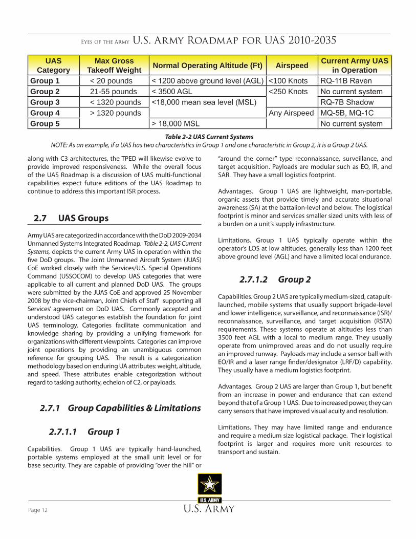
“around the corner” type reconnaissance, surveillance, and target acquisition. Payloads are modular such as EO, IR, and SAR. They have a small logistics footprint.
Advantages. Group 1 UAS are lightweight, man-portable, organic assets that provide timely and accurate situational awareness (SA) at the battalion-level and below. The logistical footprint is minor and services smaller sized units with less of a burden on a unit’s supply infrastructure.
Limitations. Group 1 UAS typically operate within the operator’s LOS at low altitudes, generally less than 1200 feet above ground level (AGL) and have a limited local endurance.
2.7.1.2 Group 2
Capabilities. Group 2 UAS are typically medium-sized, catapult-launched, mobile systems that usually support brigade-level and lower intelligence, surveillance, and reconnaissance (ISR)/reconnaissance, surveillance, and target acquisition (RSTA) requirements. These systems operate at altitudes less than 3500 feet AGL with a local to medium range. They usually operate from unimproved areas and do not usually require an improved runway. Payloads may include a sensor ball with EO/IR and a laser range finder/designator (LRF/D) capability. They usually have a medium logistics footprint.
Advantages. Group 2 UAS are larger than Group 1, but benefit from an increase in power and endurance that can extend beyond that of a Group 1 UAS. Due to increased power, they can carry sensors that have improved visual acuity and resolution.
Limitations. They may have limited range and endurance and require a medium size logistical package. Their logistical footprint is larger and requires more unit resources to transport and sustain.
along with C3 architectures, the TPED will likewise evolve to provide improved responsiveness. While the overall focus of the UAS Roadmap is a discussion of UAS multi-functional capabilities expect future editions of the UAS Roadmap to continue to address this important ISR process.
2.7 UAS Groups
Army UAS are categorized in accordance with the DoD 2009-2034 Unmanned Systems Integrated Roadmap. Table 2-2, UAS Current Systems, depicts the current Army UAS in operation within the five DoD groups. The Joint Unmanned Aircraft System (JUAS) CoE worked closely with the Services/U.S. Special Operations Command (USSOCOM) to develop UAS categories that were applicable to all current and planned DoD UAS. The groups were submitted by the JUAS CoE and approved 25 November 2008 by the vice-chairman, Joint Chiefs of Staff supporting all Services’ agreement on DoD UAS. Commonly accepted and understood UAS categories establish the foundation for joint UAS terminology. Categories facilitate communication and knowledge sharing by providing a unifying framework for organizations with different viewpoints. Categories can improve joint operations by providing an unambiguous common reference for grouping UAS. The result is a categorization methodology based on enduring UA attributes: weight, altitude, and speed. These attributes enable categorization without regard to tasking authority, echelon of C2, or payloads.
2.7.1 Group Capabilities & Limitations
2.7.1.1 Group 1
Capabilities. Group 1 UAS are typically hand-launched, portable systems employed at the small unit level or for base security. They are capable of providing “over the hill” or
Table 2-2 UAS Current SystemsNOTE: As an example, if a UAS has two characteristics in Group 1 and one characteristic in Group 2, it is a Group 2 UAS.
UAS Category
Max Gross Takeoff Weight Normal Operating Altitude (Ft) Airspeed Current Army UAS
in OperationGroup 1 < 20 pounds < 1200 above ground level (AGL) <100 Knots RQ-11B RavenGroup 2 21-55 pounds < 3500 AGL <250 Knots No current systemGroup 3 < 1320 pounds <18,000 mean sea level (MSL) RQ-7B ShadowGroup 4 > 1320 pounds Any Airspeed MQ-5B, MQ-1CGroup 5 > 18,000 MSL No current system

Eyes of the Army U.S. Army Roadmap for UAS 2010-2035
U.S. Army Page 13
radars, lasers, communications relay, SIGINT, AIS, weapons, and supplies. Group 5 UAS must meet DoD airworthiness standards prior to operation in NAS.
Advantages. Group 5 UAS are the largest of all the groups. Range, endurance, airspeed, and altitude are the greatest in this group. Group 5 UAS cover a much larger area than all other UAS.
Limitations. Group 5 UAS require improved areas for launch and recovery. The logistics footprint may approach that of manned aircraft of similar size. Group 5 UAS logistics footprint is similar to manned aircraft of similar size and has stringent airspace requirements. UAS that typically operate BLOS, lack of SATCOM could force LOS operations.
2.8 Goals and Objectives
The following goals and objectives support the Army’s vision for the development and employment of a family of UAS. They also support the goals and objectives established in the Office of the Secretary Defense (OSD) FY 2009 – 2034 Unmanned Systems Integrated Roadmap. They are not all-inclusive, but serve as Army core competencies for science and technology (S&T), research, development, test, and evaluation (RDT&E) efforts to produce right-sized, lighter, longer endurance, and increased payloads capabilities that support all levels of operation, but with emphasis on tactical support to the warfighter.
Goal 1: Improve the effectiveness of the Army UAS through improved integration and Joint force collaboration.
Objective 1.1: Conduct and share UAS technology development with Army, COCOM, and Joint Services.
Objective 1.2: Participate in Army Limited User Test and Joint experimentation.
Goal 2: Support S&T and RDT&E activities to increase the level of autonomy, as determined by the Warfighter for each specific platform.
Objective 2.1: Determine the capabilities the Warfighter needs to be automated or autonomous.
Objective 2.2: Develop autonomous behaviors to enable independent tactical mission capabilities.
Goal 3: Expedite the transition of UAS technologies from S&T through RDT&E activities into the hands of the Warfighter.
2.7.1.3 Group 3
Capabilities. Group 3 UAS are larger systems than Group 1 and 2 UAS. They operate at medium altitudes and usually have medium to long range and endurance. Their payloads may include a sensor ball with EO/IR, LRF/D, SAR, moving target indicator, SIGINT, communications relay, explosive hazards detection, and CBRNE detection. Some Group 3 UAS carry weapons. They usually operate from unimproved areas and may not require an improved runway.
Advantages. Group 3 UAS have a wider array of sensors, as well as the capability of weaponization for precision guided munitions.
Limitations. Group 3 UAS typically have decreased endurance when carrying weapons. The logistics footprint typically includes ground support equipment and a larger logistics footprint.
2.7.1.4 Group 4
Capabilities. Group 4 UAS are relatively large systems, operate at medium to high altitudes, and have extended range and endurance. Group 4 payloads may include EO/IR, radars, lasers, communications relay, SIGINT, automated identification system (AIS), and weapons. Group 4 UAS must meet DoD airworthiness standards prior to operation in NAS.
Advantages. Group 4 UAS benefit from an increase in power from that of Group 3. Group 4 UAS have the capability to carry larger or more numerous munitions payloads without sacrificing as much endurance as Group 3.
Limitations. Group 4 UAS typically have decreased endurance when carrying weapons. Group 4 UAS normally require improved areas for launch and recovery (i.e., runways). Group 4 UAS logistics footprint is similar to manned aircraft of similar size and has stringent airspace requirements. Lack of satellite communication (SATCOM) links could inhibit BLOS capability for some Group 4 UAS.
2.7.1.5 Group 5
Capabilities. Group 5 UAS are the largest systems, operate in the medium to high altitude environment, and typically have the greatest range/endurance and airspeed. They perform specialized missions including broad area surveillance and penetrating attacks. Group 5 payloads may include EO/IR,
Eyes of the Army U.S. Army Roadmap for UAS 2010-2035
U.S. ArmyPage 14
Objective 3.1: Develop comprehensive transition plans to address Warfighter needs early in the development process.
Goal 4: Achieve greater interoperability among system controls, communications, data products, data links, and payloads/mission equipment packages on UAS.
Objective 4.1: Field common secure communications systems for control and sensor data distribution in BLOS and LOS missions. Incorporate capability to prevent interception, interference, jamming, and hijacking.
Objective 4.2: Emphasize common payload interface standards across UAS to promote greater mission versatility.
Goal 5: Foster the development and practice of TTP that enable safe and effective operations between manned systems and UAS.
Objective 5.1: Promote the development, adoption, and enforcement of government, international, and commercial standards for the design, manufacturing, testing, and safe operation of UAS.
Objective 5.2: Develop and field UAS that can “sense” and autonomously avoid other objects to provide a level of safety equivalent to comparable manned systems.
Goal 6: Implement standardized and protected positive control measures with the Joint community for UAS, their associated armament, unmanned ground vehicles (UGV), and unattended ground sensors (UGS).
Objective 6.1: Adopt a standard UAS architecture and associated standards for armed UAS, UGV, and UGS.
Goal 7: Ensure test capabilities that support the fielding of UAS are effective, suitable, and survivable.
Objective 7.1: Ensure the appropriate test infrastructure is available for developmental and operational testing of UAS.
Goal 8: Enhance the current logistical support process for UAS.
Objective 8.1: Adopt innovative strategies to provide cost effective logistical support to UAS to satisfy operation tempo (OPTEMPO) requirements.
Objective 8.2: Promote the development of engineering design to increase the reliability, availability, and maintainability of UAS to sustain the Warfighter needs.
Objective 8.3: Promote and develop CBM utilizing health
management usage system (HUMS) technology.
Objective 8.4: Promote the development of engineering design to reduce the susceptibility and vulnerability of UAS to increase their combat survivability and reduce the time required to return battle damaged systems to the Warfighter.
Goal 9: Develop an airworthiness qualification program to achieve Level 1.
Objective 9.1: Develop an airworthiness qualification program to achieve Level 2 airworthiness, dependent upon funding and mitigated risk.
Goal 10: Training
Objective 10.1: Develop overarching UAS training strategy
Objective 10.2: Improve training aids, devices, simulators and simulations (TADSS)
Objective 10.3: Coordinate rapid access to training airspace for individual, crew, collective, combined arms, and Joint training
Objective10.4: Integrate UAS operations into all Army professional military education (PME)
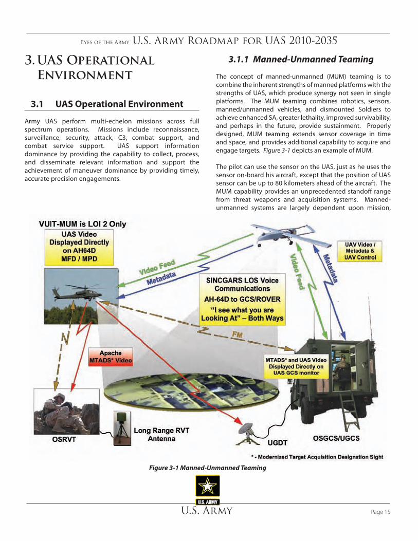
Eyes of the Army U.S. Army Roadmap for UAS 2010-2035
U.S. Army Page 15
3. UAS Operational Environment
3.1 UAS Operational Environment
Army UAS perform multi-echelon missions across full spectrum operations. Missions include reconnaissance, surveillance, security, attack, C3, combat support, and combat service support. UAS support information dominance by providing the capability to collect, process, and disseminate relevant information and support the achievement of maneuver dominance by providing timely, accurate precision engagements.
3.1.1 Manned-Unmanned Teaming
The concept of manned-unmanned (MUM) teaming is to combine the inherent strengths of manned platforms with the strengths of UAS, which produce synergy not seen in single platforms. The MUM teaming combines robotics, sensors, manned/unmanned vehicles, and dismounted Soldiers to achieve enhanced SA, greater lethality, improved survivability, and perhaps in the future, provide sustainment. Properly designed, MUM teaming extends sensor coverage in time and space, and provides additional capability to acquire and engage targets. Figure 3-1 depicts an example of MUM.
The pilot can use the sensor on the UAS, just as he uses the sensor on-board his aircraft, except that the position of UAS sensor can be up to 80 kilometers ahead of the aircraft. The MUM capability provides an unprecedented standoff range from threat weapons and acquisition systems. Manned-unmanned systems are largely dependent upon mission,
Figure 3-1 Manned-Unmanned Teaming

Eyes of the Army U.S. Army Roadmap for UAS 2010-2035
U.S. ArmyPage 16
3.1.2 Command & Control of Army UAS
UAS must demonstrate interoperability on a number of levels:
Materiel: The Army’s One System Ground Control Station (OSGCS) for its MQ-5 Hunter, RQ-7 Shadow, and MQ-1 Warrior UAS is an example of this level of existing materiel interoperability. The UGCS will further promote open architecture and incorporate OSD/Joint unmanned system interoperability profiles (USIP).
Procedural: The ability of military UAS to share the NAS and international airspace with commercial airliners and general aviation is an example of this level of future procedural interoperability.
Tactical: The Army requires the capability for Army UAS operators to pass UA control to a forward ground unit for mission execution. Adding a transceiver to OSRVT is a near-term solution to this capability requirement.
Operational: The Army is developing common operating architecture within the Joint UAS community that facilitates interoperability between Services. USIP is a step in this direction.
3.2 UAS Interoperability with Joint Forces
Joint interoperability is the ability for Joint forces to execute their assigned missions seamlessly. When properly implemented, it serves as a force multiplier and can simplify ISR, logistics or other support provided to the force. Department of Defense Directive 5000.1 established the requirement to acquire systems and families of systems that are interoperable. The current Army UAS supporting Joint operations are ERMP (quick reaction capability [QRC] 1 and 2, Warrior A, and ERMP Block 0), Hunter, and Shadow. Although the Raven UAS has limitations in range (10 kilometers) and endurance (maximum of 90 minutes), USSOCOM, U.S. Marine Corps (USMC), U.S. Air Force (USAF) and the National Guard currently utilize the Raven in Joint operations. The range, endurance and interoperability of Raven will increase with the fielding of digital data link and other upgrades in FY 2010. The commonality of control hardware and software across the small UAS family, including WASP, Puma All Environment Capable Variant, Switchblade, and other emerging platforms, will further extend the utility of the family to joint applications.
enemy, terrain, troops, time, and civil considerations. The transfer of sensor data between the manned system and UAS reduces risk to both platforms and increases mission effectiveness and survivability rates of friendly forces. Environmental conditions affect the added efficiency of MUM employment.
While conducting a border surveillance mission we identified six men moving tactically for no apparent reason and noticed that the last man was sweeping the group’s tracks. Well-placed brush camouflage covered each individual’s head. We provided persistent observation for a couple of days while simultaneously keeping the supported ground unit informed. We followed the group to a particular area and observed people coming in and out of small caves. We reported that most of the suspected personnel were carrying RPK, AK47, and Dragunov sniper rifle weapons, confirming they were enemy. We engaged with two Hellfire missiles from our MQ-1B Warrior-A. We were out of ammo so we conducted a MUM target handover with two AH-64D helicopters, who engaged the target with additional missiles while we continued to laser designate the target. When the ground troops arrived to gather intelligence, there was no resistance due to our engagement. The area turned out to be a hide site that supported numerous terrorist cells and contained food, water, rockets, mortars, small arms, and IED making material. We also found that underground tunnels reinforced with steel construction linked the caves. SFC Phillip A. Scibelli, Alpha Troop, TF ODIN

Eyes of the Army U.S. Army Roadmap for UAS 2010-2035
U.S. Army Page 17
3.3 UAS Interoperability with Other Government Agencies
The Army achieves other government agency interoperability by buying common components, systems, software and by building systems to common standards. An example of this is the Army National Guard (Title 32), support to governmental agencies such as the customs and border protection using Army UAS. The way ahead will be interoperability between Army active / Reserve component, other DoD Services, and government agencies, in incidences of natural disaster and states of emergency where ground lines of communications are interrupted or non- existent. The Department of Homeland Security, Department of Energy, Department of Forestry, and National Geological Survey Service are rapidly acquiring SUAS to provide border security, locate forest fires, provide rapid response to natural disasters, and conduct scientific research in accordance with Title 50, U.S. Code.
Army RSTA and Joint ISR operations require continuous surveillance and reconnaissance to provide timely indications and warning of an imminent or impending threat attack. UAS conducting RSTA missions provide commanders with current data on enemy terrain, organization, infrastructure, and forces necessary for planning theater campaigns and major operations, including contingencies. UAS also support adaptive, real-time planning for current operations, including monitoring enemy centers of gravity, conventional attack capabilities, enemy offensive and defensive positions, deception postures, and battle damage assessment (BDA).
A limitation within the Army and Joint community, with respect to Groups 1-3, is the inability of the UAS GCS to process, prepare, and disseminate FMV and metadata information from RSTA missions. Electronic mail can have single video frames as well as short video clips attached and transmitted via the Secret Internet Protocol Router Network (SIPRNET), thereby providing imagery information to the supported command by tactical communications. UAS units have the capability to furnish recorded FMV of missions to service intelligence agencies for analysis. Intelligence personnel disseminate information in digital message format and freeze frame imagery (national imagery transmission format) to the theater intelligence system via ABCS and other Joint systems.
3.2.1 Army UAS Applied to Joint Capability Areas
This Roadmap compares current and projected UAS capabilities against Joint capability areas (JCA) which outline how the Army UAS will contribute to future Army and Joint missions that support the Warfighter. Each JCA represents a collection of related missions and tasks typically conducted to bring about the desired effects associated with that capability. Of the nine defined JCAs, unmanned systems contribute to eight: battle space awareness, force application, command and control, protection, sustainment, building partnerships, force support, and net centric. Current technology and future advancements enable single platforms to perform a variety of missions across multiple capability areas representing an opportunity for the Army to achieve a greater return on investment. This technology provides opportunities for existing and future Army UAS to operate in the Joint environment with the other Services.
“Taking a Joint approach on UAS issues will allow us to rapidly develop force capabilities from concept and capability development through employment by identifying, linking and synchronizing all of our activities, so we can give the best capability to Joint Warfighters who are fighting a very elusive, thinking and adaptive adversary.” General William S. Wallace, commander, Training and Doctrine Command, Army News Service, “Leaders Discuss New Joint Unmanned Aerial Operations”, July 2008
Eyes of the Army U.S. Army Roadmap for UAS 2010-2035
U.S. ArmyPage 18
3.4 UAS Interoperability with Coalition Partners
Today, Army UAS interoperability with coalition partners is limited. However, there are several initiatives, such as the NATO STANAG 4586 compliant ground control system for UAV, STANAG 4670 Designated UAV Operator training requirements, NATO Joint Air Power Competence Centre’s “Guidance on Employment Principles for UAS in NATO” concept of employment (CONEMP), which describe the standards required to achieve UAS interoperability among coalition partners. Compliance with STANAG 4586 allows NATO member nations to support military operations using their own UAVs and ground control station equipment. This increases interoperability and allows member nation UAV to share data and information processed through a common ground interface. STANAG 4586, formally ratified by NATO in 2002, defines five levels of UAV interoperability as previously outlined in Table 2-1.
Payload data products will be STANAG compliant. STANAG 4607 allows other services and NATO partners to exploit GMTI data. Compliance with STANAG 4609 provides interoperability of FMV and large volume streaming data. Still imagery, such as snapshots from video and SAR imagery adheres to the national imagery transmission format. For stored information, NATO has created coalition-shared databases (CSD), which allows sharing of information between intelligence sources. STANAG 4559 defines the CSD interface. This will aid in sharing of live and stored information between Coalition partners.
Bridging technologies offer the opportunity for dissimilar platforms to communicate a variety of data including targeting, C2, and sensor products between platforms, command nodes, and information dissemination networks.
NATO allies, such as Denmark, are procuring the Raven to support operations in Afghanistan. Requests from other nations for both foreign military sale cases and UAS procurement directly from prime vendors will continue to increase.

Eyes of the Army U.S. Army Roadmap for UAS 2010-2035
U.S. Army Page 19
full spectrum and networked dilemmas. These dilemmas will be embedded in the clutter of local populations, possess a wide range of old to advanced technologies – including the possibility of weapons of mass destruction. They will operate conventionally and unconventionally employing adaptive and asymmetric combinations of traditional, irregular and criminal tactics using traditional military capabilities in old and new ways. Threats will challenge U.S. access – directly and indirectly. They will attack U.S. national and political will with very sophisticated information campaigns as well as seek to conduct physical attacks on the U.S. homeland. Military operations will result in demanding long-term commitments at extended distances that require a wide range of inter-agency and non-military tools to resolve. All of which will be carried out under the unblinking eye of an omni-present formal and informal media potentially giving local events global significance.
The Army expects that a near-peer symmetric military competitor to the United States will not exist for the next 25 years. However, U.S. forces will operate in a global environment of increasing instability and uncertainty. Most existing regional powers will grow, new ones will appear, and transnational and non-state actors will increasingly influence world politics. Opponents will develop strategies that are adaptive, asymmetric, and primarily defensive in nature at the strategic and operational levels. Potential opponents will design their forces and tactics around the ability to exploit U.S. vulnerabilities and patterns while countering or mitigating U.S. strengths. The proliferation of weapons and technology will allow underdeveloped states and non-state actors to acquire significant equalizing capabilities.
Areas and types of conflict become less predictable. The U.S. ability to tailor specific forces, equipment, and training for each unique, complex mission will become increasingly difficult. The physical environment ranges from complex and densely populated urban areas comprised of subterranean infrastructure, shantytowns, and skyscraper canyons to rural and sparsely populated environments consisting of high mountains and deserts, jungles, rolling woods and grasslands. Each geographic area will possess some primitive infrastructure that will have a direct and adverse affect on the U.S.’s capability to respond. Available theater-based military or civil communications assets and/or networks will not be sufficient to support U.S. requirements alone. Civil transportation (rails, roads, bridges, etc.) are not of sufficient lane width, levelness, straightness, load bearing capacity, and size to support military operations without significant improvements. Extreme engineering efforts and resources will be required to ensure usability. Weather will always play a
4. Threat EnvironmentOperations conducted among local populations with unfamiliar cultures, often in the midst of humanitarian crisis including the potential for ethnic cleansing and mass atrocities, will characterize the Operational Environment from 2010 to 2025. Urban settings or uncertain, inaccessible lawless areas are the typical locations where operations occur. There will be an absence of local security or effective local governments and the environment will contain competing factions locked in internal conflict. The threat will be hybrid, simultaneously employing regular and irregular forces, including criminal elements to achieve their objectives. They will use an ever-changing variety of conventional and unconventional tactics to create multiple innovative, adaptive, globally connected,
“The global security environment is more ambiguous and unpredictable than in the past. Many national security and intelligence experts share the Army’s assessment that the next several decades will be characterized by persistent conflict – protracted confrontation among state, non-state, and individual actors that are increasingly willing to use violence to achieve their political and ideological ends…Future operations in this dynamic environment will likely span the spectrum of conflict from peacekeeping operations to counterinsurgency to major combat.”
2009 Army Posture Statement

Eyes of the Army U.S. Army Roadmap for UAS 2010-2035
U.S. ArmyPage 20
(direct/indirect fire), IO, and EA. By networking the ground station with other systems, any threat that compromises the network will introduce a risk to the UAS. The major threat to the UAS communications links will be electronic attack.
Threat C3 capability will often be commercial off-the-shelf equipment available on the open market. Weapons and equipment incorporating sophisticated technology, but suitable for small unit operations, could include night vision sensors, ground surveillance radar, sensor-equipped unmanned air vehicles, low-energy laser blinders, and sensor-fused anti-helicopter mines.
UAS generally avoid anti-air threats in contested airspace if they lack threat detection devices or threat countermeasures. However, the Warfighter may deem it necessary to send a UA into contested airspace and risk losing it to enemy fire if the operational payoff is greater than the risk of losing the UA and its payload. To mitigate the risks of UAS operating in hostile airspace, commanders must employ support measures and tactics such as suppression of enemy air defenses, IO, changes in positive and procedural control, and direct support by other aircraft systems.
significant determining role on operations, degrading or even periodically eliminating the employment of air assets, with both manned and unmanned systems.
Future adversaries will attempt to defeat U.S. efforts to conduct full spectrum operations. This will include a combination of traditional warfare mixed with terrorism and insurgency. Because of the overall technological mismatch between future adversaries and the U.S. military, our forces will face opponents that are decentralized, distributed, amorphous, and continuous. Opponents will seek to deny the U.S. a visible military force to target and will employ insurgency and paramilitary operations. To wear down U.S. forces and national will, opponents will employ nonmilitary means, such as psychological operations, civil disobedience, and economic resistance. Opponents will employ camouflage, concealment, and deception tactics and techniques to include the use of human shields.
Regional powers will continue to field large mechanized forces (or mobile armies) supported by rotary and fixed-wing aircraft, armored vehicles, mobile artillery, ballistic and cruise missiles, longer-range air defense, and antitank weapons. These powers will employ electronic warfare (EW) systems, ground and airborne reconnaissance, surveillance, target acquisition sensors, and a sophisticated C3 system that rival our capabilities. Most will be capable of offensive chemical warfare and some will acquire or improve their capacity for biological and tactical nuclear warfare. Some states could eventually deploy high-energy laser weapons for air defense of key assets and possess a capability for information operations (IO). Additionally, most states are also advancing their own UAS and counter-UAS capabilities.
Smaller scale threats also will exist such as light forces experienced in local warfare. Typically, the enemy will operate in complex terrain (cities, jungles, mountains) for concealment while exploiting the indigenous environment and its inhabitants for surprise and shielding. Armed combatants will employ with infantry small arms, rocket propelled grenades, light artillery, anti-aircraft machineguns, man-portable anti-tank and surface-to-air missiles, and other types of locally produced weapons (e.g., explosive hazards, helicopter landing zone mines).
Typically, the most critical threat to UAS will come from hostile integrated air defense systems. Threat weapons include direct-fire weapons such as anti-aircraft artillery; indirect-fire weapons, surface to air missiles (SAM); EW systems; electro-optic countermeasures; and directed energy weapons. The major threats to the system’s ground stations are physical attack

Eyes of the Army U.S. Army Roadmap for UAS 2010-2035
U.S. Army Page 21
and specifically tailored data sets to multiple users. This will reduce bandwidth and increase the value of information transmitted.
Fires. UAS support all aspects of the sensor-to-shooter cycle. UAS can significantly shorten the sensor-to-shooter response time by performing aided target recognition, tracking targets, laser-designating targets and providing battle damage assessment. UAS will assist in calling for fire and adjusting indirect (mortars and artillery) fire missions. When weaponized, UAS will provide lethal or non-lethal effects. For instance, information operations currently use EW payloads.
Protection. UAS are able to maintain a persistent security presence and quickly respond to emerging threats during maneuver, convoy operations, and near fixed bases. UAS participation in maneuver, fires and intelligence contribute to the protection of the force by providing early warning, target tracking, and reconnaissance of named area of interest. Similarly, protective technologies contribute to the survivability of individual UAS. Teaming and collaboration with manned and unmanned systems adds the combined suite of effects to provide overwatch and suppression in support of UAS operations. The UAS provide the capability to find CBRNE materiel or hazards and to survey the affected areas, while minimizing the exposure to the Soldier.Sustainment. Future systems will support unmanned autonomous supply/ retrograde, convoy security, medical evacuation, pipeline surveillance, in-transit visibility communication relay, warehousing, seabasing, and mortuary affairs operations capability. Sustainment/cargo UAS employment will ensure responsive and uninterrupted operations. The UAS will improve in reliability, availability, maintainability, and testability (RAM-T). Modularity, commonality, easier maintenance, and greater efficiency of operation will reduce supportability requirement.
Command & Control. Current systems extend the range of C2, and add an additional aerial layer to the network through a robust network extension capability. Future systems will extend the network and provide gateways for cross banding with extension and augmentation for BLOS during periods of absent SATCOM and degraded BLOS.
5.2 UAS Echelons
The Army employs UAS across all echelons. Battalion-level and below UAS missions are close-range (less than 25 kilometers), short-duration missions (one to two hours) generally operating
5. Army UAS Employment
5.1 UAS Support of Warfighter Functions
Ultimately, UAS capabilities will evolve to support the Army Warfighter Functions to an increasing degree. Examples of how the UAS contribute to these are:
Movement & Maneuver. UAS move in coordination and collaboration with formations of ground (and air) systems synchronized with lethal and non-lethal capabilities to achieve positions of advantage at the commander’s time and place of choosing. The appropriate pairing of UAS attributes – speed, endurance, stealth, etc. – with the supported formation’s behavior makes teaming and mutual support possible as well as effective. Intelligence. UAS are integrated components of the ISR capability. UAS provide flexible, responsive platforms equipped with a variety of mission payloads to support the commander’s intelligence gathering requirements. Over time, improved UAS incorporate increasing capability to process data on board, transmit information pertinent to the Soldier,
“The advances you have underwritten in weapons systems and individual equipment; in munitions; in command, control, and communications systems; in intelligence, surveillance and reconnaissance capabilities; in vehicles and counter-IED systems and programs; and in manned and unmanned aircraft [emphasis added] have proven invaluable in Iraq.”General David H. Petraeus, commander, Multi-National Force-Iraq, Report to Congress on the Situation in Iraq, 10-11 September 2007

Eyes of the Army U.S. Army Roadmap for UAS 2010-2035
U.S. ArmyPage 22
agile, more lethal force to positions of advantage. Organic and direct UAS support at the tactical level allows commanders to analyze and weight the effort, provide responsive support to subordinate echelons, and shorten the gap between sensor and shooter.
5.2.1 Battalion-Level and Below
Battalion-level and below UAS operations are close-range (less than 25 kilometers), short-duration missions (one to two hours), generally operating below the coordinating altitude, and are thoroughly integrated into the scheme of maneuver as an organic asset supporting operations. The primary system at the battalion and below level is the SUAS, RQ-11B, Raven (Figure 5-2). The Raven is a man-portable, hand-launched, small-unit UAS. It provides reconnaissance and surveillance capability to support SA, security, target acquisition (TA), and BDA at LOS (ranges up to 10 kilometers). Military Occupational Specialty (MOS) non-specific personnel can program, launch, fly, retrieve, and
below the coordinating altitude and thoroughly integrated with ground forces as an organic asset supporting maneuver operations. Brigade-level UAS missions are medium-range (less than 125 kilometers), medium-duration missions (five to 10 hours), and integration with ground forces and other aviation assets. Division-level and higher UAS missions are extended-range (200 kilometers or more), long-duration (16 hours or more based on UA), in direct support or general support of tactical to operational missions.
Figure 5-1, Risk versus Time by Echelon chart, depicts the Army UAS support paradigm. It compares the risk level against the time with which that echelon has to either shape or react in their combat mission set. The lower the echelon, the more risk, and thus there is a greater requirement for dedicated, reliable, and consistent support that can be dynamically re-taskable and responsive to rapidly changing situations. In complex environments, the risk of loss is greater and the time to react is much less. Risk versus time is synonymous with the tenets of information warfare in that it places a premium on gaining information dominance to enable maneuver by a smaller, more
Army Decision Dominance Focus
PLT
CO BN
BD
E
DIV
CO
RPS
Reg
ion
Increased reliance on Joint Interdependencies
Increased requirement for dynamic retasking, levels of control and
dedicated, integrated UAS supportR
ISK
TIM
E
Situational Awareness, Dynamic Action/ReactionTime-sensitivity of Info/IntelForce Protection
Size of Area of Interest,Time and Ability to
Shape Fight
• Risk decreases as echelon increases• Time to react increases as echelon increases• Complex terrain increases risk, need for SA, and time-sensitivity of intel/info• Critical for lower echelons to have dynamic ability to rapidly confirm/deny reports
Figure 5-1 Risk vs. Time by Echelon

Eyes of the Army U.S. Army Roadmap for UAS 2010-2035
U.S. Army Page 23
weather sensing, weapons delivery, tailored or high priority communications and data relay, psychological operations support, supply delivery, and covert reconnaissance. These missions and roles will become possible as hardware miniaturization continues in concert with advances in materials, power supply, and data management.
5.2.2 Brigade-Level
Organic, medium-range (less than 125 kilometers), medium-duration missions (five to ten hours), and full integration with ground forces and other aviation assets characterize UAS operations at the brigade-level. The primary UAS supporting the BCT, Battlefield Surveillance Brigade, Fires Brigade, and Army Special Operations Forces (ARSOF) is the Shadow. The Shadow UAS are organic to the Infantry, Heavy, Stryker brigades, and Army Special Operations Forces (SOF). The Shadow executes reconnaissance, surveillance, and C2 support (communications relay) for improved SA, TA, BDA, and
maintain the Raven UAS. Ravens are currently supporting operations in OIF and OEF.
The SUAS will field a proof of concept system beginning in FY 2010 that will enhance the capabilities with the addition of smaller fixed wing aircraft such as WASP a larger aircraft, such as Puma AECV. A small rotary wing aircraft such as the Class I Block 0 and gMAV type systems will be fielded to the enhanced IBCT and forces within the functional brigades. Commonality of control hardware and software between these platforms ensure a fluid integration into unit operations. Further exploration of mini-UAS platforms will address unique needs identified at echelons battalion and below. The Army will place significant effort on interoperability of SUAS with unmanned grounds vehicles and unattended sensors. Interaction of SUAS and larger UAS within a broader environment of data sharing, command and control and mission execution will expand the role of unmanned systems and their application on the battlefield. New roles for SUAS will include SIGINT, EW, day/night all
Figure 5-2 Raven Operations and Missions

Eyes of the Army U.S. Army Roadmap for UAS 2010-2035
U.S. ArmyPage 24
5.3 Operational Vignettes
The best way to convey the operational utility and flexibility of UAS is with vignettes. Figures 5-3 through 5-10 describe full spectrum operation vignettes utilizing UAS with manned aircraft, vehicles, and Soldiers. Full spectrum operations include offensive, defensive, and stability or civil support operations. Figure 5-11 depicts a battlefield surveillance brigade conducting multi-intelligence operations and Figure 5-12 depicts a Special Forces Operational Detachment-A team eliminating a HVT.
extended communications reach at LOS ranges. The ERMP UAS companies are organic to the Combat Aviation Brigade (CAB). The Army is also studying Shadow UAS organic in the Air Cavalry Squadron to emphasize MUM with CAB aircraft. In the future, the Brigade Support Battalion, within the Brigade Combat Team, may also have UAS in this category to be able to provide sustainment, whether by airland or airdrop, as well as the performance of a retrograde function to COPs and FOBs.
5.2.3 Division-Level and Higher
Both DS and GS tactical to operational missions at extended-range (200 kilometers or more), long-duration (16 hours or more) characterize division-level and higher UAS operations. The MQ-1C and MQ-5B Hunter provide multiple payload and strike capabilities in support of division and higher-level operations. These operations require detailed cross echelon planning and integration. From a Joint perspective future sustainment cargo UAS may be employed at the operational level in support of ship to shore (seabasing) and intra-theater lift mission roles. The Sustainment Brigades may have UAS to be able to provide sustainment to brigades located in their area of operations or if needed to unit COPs by either airland or airdrop.
Figure 5-3 Offensive Operations
“We know the integration of unmanned aircraft systems with our maneuver forces into a single, cohesive combat capability is paramount.”Lieutenant General J. D. Thurman, Deputy Chief of Staff, G3/5/7, AUSA Army Aviation Symposium, 6 January 2010

Eyes of the Army U.S. Army Roadmap for UAS 2010-2035
U.S. Army Page 25
determine threat veracity. The ERMP confirms JSTARS hits, refines the target area to a mosque within Town 1, a palm grove along main supply route Red, and a suspected safe house in Town 3.
The division reclaims operational control of the ERMP, therefore, 1st BCT dynamically re-tasks Shadow support from 2nd Battalion to 1st Battalion AO to confirm or deny ERMP data. This dynamic tasking authority is why UAS are crucial to the Army in combat operations.
In Figure 5-4, 1st BCT conducts presence patrols in vicinity of Towns 1 and 3 over irregular intervals to avoid tipping off possible HVTs and compromising weapon cache sites.
HUMINT gathered from Soldiers and Shadow FMV identify between 15-20 unidentified personnel moving between Towns 1, 3, and the palm grove. Also noted were significant heat signatures within the palm grove indicating a possible cache site.
In Figure 5-5, A/1-1BCT attacks to destroy the shed/cache within the palm grove and simultaneously conducts an infiltration into Town 1 to clear enemy combatants and
5.3.1 Offensive Vignette
Figures 5-3 through 5-6 describe an offensive operation utilizing ERMP, Shadow, and Raven UAS with manned aircraft, vehicles, and Soldiers. Offensive operations are combat operations conducted to defeat and destroy enemy forces and seize terrain, resources, and population centers. Executing offensive operations compel the enemy to react, creating or revealing weaknesses that the attacking force can exploit. Successful offensive operations place tremendous pressure on defenders, creating a cycle of deterioration that can lead to their disintegration.
In Figure 5-3, 1st BCT conducts reconnaissance of a possible insurgency staging area to confirm or deny insurgency presence in a suspected area.
JSTARS reports multiple GMTI tracks in an outlying area of 1st BCT’s AO that does not have a frequent friendly presence. JSTARS observes potential insurgents moving into the area possibly coinciding with evening prayer in Town 1.
1st BCT requests division ERMP for a three-day sequence of persistent stare operations in order to refine GMTI hits and
Figure 5-4 Offensive Operations
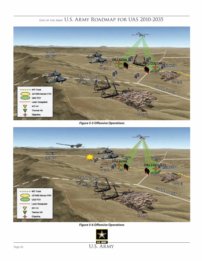
Eyes of the Army U.S. Army Roadmap for UAS 2010-2035
U.S. ArmyPage 26
Figure 5-6 Offensive Operations
Figure 5-5 Offensive Operations

Eyes of the Army U.S. Army Roadmap for UAS 2010-2035
U.S. Army Page 27
operator identifies a target fleeing the western edge of the palm grove. 1st BCT requests immediate support of the division ERMP to identify and engage the fleeing target. This enables the Shadow to stay on station in support of the clearing operations in vicinity of Objectives AZAN and COCONUT. The division engages the fleeing hostile truck with the ERMP using a Hellfire missile. The ERMP, Shadow, and Raven UAS provide initial BDA.
5.3.2 Defensive Vignette
Figures 5-7 through 5-8 describes a defensive operation utilizing ERMP, Shadow, and Raven UAS with manned systems and Soldiers. Defensive operations are combat operations conducted to defeat an enemy attack, gain time, economize forces, and develop conditions favorable for offensive or stability operations. Defensive operations counter enemy offensive operations. They defeat attacks and destroy as much of the attacking enemy as possible. Defensive operations retain terrain, guard populations, and protect critical capabilities
deny resupply of the suspected mosque. The Shadow has been on station to observe the landing zone (LZ) continuously to determine enemy presence. At H-4 minutes, the Apaches arrive on station to conduct security prior to the CH-47 arrival to insert A/1-1BCT on Objectives COCONUT and AZAN.
1/A/1-1BCT attacks through the palm grove to Objective COCONUT as 2/A/1-1BCT and 3/A/1-1BCT attack to secure Town 1 vicinity Objective AZAN. The Shadow FMV feeds provide continuous reconnaissance and security capability, situational awareness, and targeting information to both the 1-1BCT tactical operations center (TOC) and to the attacking Soldiers on the ground using the OSRVT linkage.
In Figure 5-6, immediately following the initial insertion, platoons employ Raven UAS to provide updated electro-optical imagery as they finalize clearing actions. The Shadow provides laser designation on Objectives AZAN and COCONUT, which allows for MUM with the AH-64. As the Shadow and AH-64 clear the objectives, the Shadow
Figure 5-7 Defensive Operations
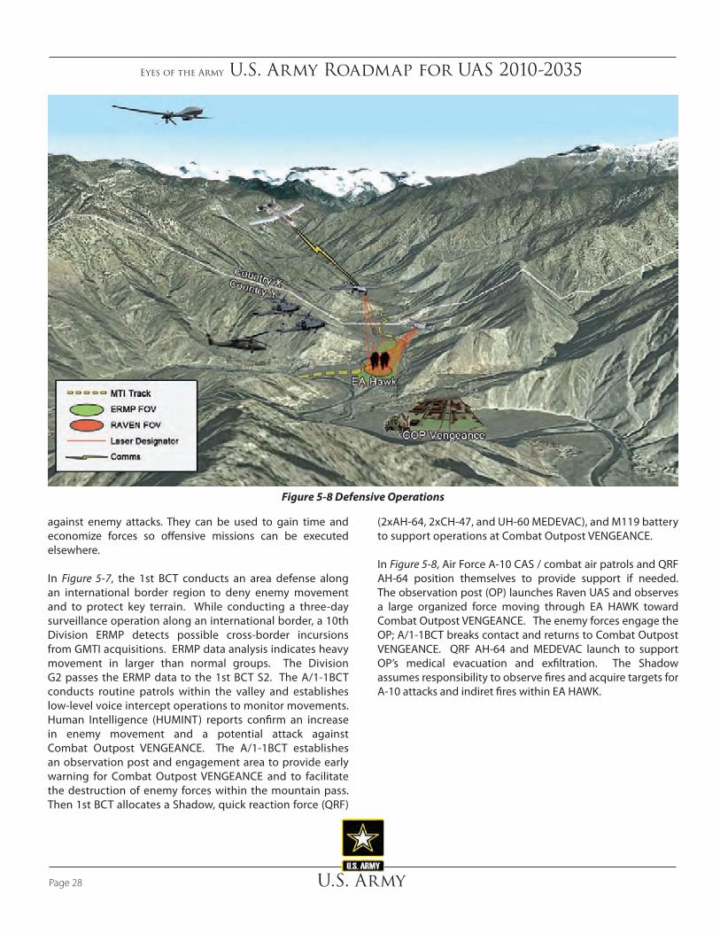
Eyes of the Army U.S. Army Roadmap for UAS 2010-2035
U.S. ArmyPage 28
Figure 5-8 Defensive Operations
(2xAH-64, 2xCH-47, and UH-60 MEDEVAC), and M119 battery to support operations at Combat Outpost VENGEANCE.
In Figure 5-8, Air Force A-10 CAS / combat air patrols and QRF AH-64 position themselves to provide support if needed. The observation post (OP) launches Raven UAS and observes a large organized force moving through EA HAWK toward Combat Outpost VENGEANCE. The enemy forces engage the OP; A/1-1BCT breaks contact and returns to Combat Outpost VENGEANCE. QRF AH-64 and MEDEVAC launch to support OP’s medical evacuation and exfiltration. The Shadow assumes responsibility to observe fires and acquire targets for A-10 attacks and indiret fires within EA HAWK.
against enemy attacks. They can be used to gain time and economize forces so offensive missions can be executed elsewhere.
In Figure 5-7, the 1st BCT conducts an area defense along an international border region to deny enemy movement and to protect key terrain. While conducting a three-day surveillance operation along an international border, a 10th Division ERMP detects possible cross-border incursions from GMTI acquisitions. ERMP data analysis indicates heavy movement in larger than normal groups. The Division G2 passes the ERMP data to the 1st BCT S2. The A/1-1BCT conducts routine patrols within the valley and establishes low-level voice intercept operations to monitor movements. Human Intelligence (HUMINT) reports confirm an increase in enemy movement and a potential attack against Combat Outpost VENGEANCE. The A/1-1BCT establishes an observation post and engagement area to provide early warning for Combat Outpost VENGEANCE and to facilitate the destruction of enemy forces within the mountain pass. Then 1st BCT allocates a Shadow, quick reaction force (QRF)

Eyes of the Army U.S. Army Roadmap for UAS 2010-2035
U.S. Army Page 29
rescue, communications relay, and logistical sustainment. DoD (Northern Command [NORTHCOM]) approves the use of the UAS for disaster relief and establishes an emergency operations center (EOC) on Naval Air Station Key West to coordinate all recovery operations. Naval Air Station Key West serves as the staging area for the initial response package consisting of C-130s, CH-47s, sustainment/cargo UAS, and an ERMP to conduct IAA, search and rescue, aerial resupply, and communications relay.
In Figure 5-10, a possible biohazard leak prompts a UAS fitted with biological detection equipment to make the initial recon of the airport. The UAS transmits FMV to the OSRVT in the EOC. Due to a detected leak, UAS and robotics will execute all missions in favor of manned operations. In addition, NORTHCOM allocates an ERMP to cover the affected area and starts transmitting over the same band to the EOC, allowing for immediate action on both the biohazard and search and rescue efforts. ERMP performs communications relay missions to facilitate C2 between maritime effort, EOC, staging areas, and other UAS operations. The EOC re-tasks the sustainment/cargo UAS to the search and rescue effort in order to facilitate delivery of food and medical supplies, while the ERMP remains on station to provide situational
5.3.3 Civil Support Vignette
Figures 5-9 through 5-10 describes a civil support operation utilizing ERMP, Hunter, and Raven UAS with manned systems and Soldiers. Civil support is DoD support to U.S. civil authorities for domestic emergencies, and for designated law enforcement and other activities. Civil support includes operations that address the consequences of natural or man-made disasters, accidents, terrorist attacks, and incidents in the United States and its territories. Army forces conduct civil support operations when the size and scope of events exceed the capabilities or capacities of domestic civilian agencies.
Figure 5-9 depicts civil support operations following a natural disaster to assist the National Guard in providing incident awareness and assessment (IAA), search and rescue, communications, CBRNE, and logistical sustainment throughout the affected area. A category 5 hurricane strikes Key West destroying the Overseas Highway access bridge. The hurricane stranded an unknown number of residents and damaged a biohazard storage facility on the northeast side of the Key West airport. The governor requests immediate federal assistance, to include UAS spport, for IAA, search and
Figure 5-9 Civil Support Operations

Eyes of the Army U.S. Army Roadmap for UAS 2010-2035
U.S. ArmyPage 30
Figure 5-10 Civil Support Operations
Shadow crews. The SOF personnel in the area, on a separate mission, monitor the action via OSRVT and SIPRNET chat and assist by observing and reporting insurgent actions south of the target area.
5.3.5 Special Forces Vignette
Figure 5-12 depicts an Special Forces Operational Detachment A (ODA) team conducting an operation to eliminate a HVT. National assets working along an international border detect movement of a known HVT from Country Green into Country Blue. United States forces do not have permission to enter Country Green, but have been monitoring the HVT for months. The HVT’s movement into Country Blue allows a quick strike opportunity using SOF-coordinated assets. The JSTAR passes the HVT movement track to an Army ERMP, for use by an assigned ODA team. The ERMP establishes a three-day persistent stare operation to determine a targetable pattern. ERMP data establishes a repetitive pattern of movement between Town A and B, while the ERMP SIGINT data indicates that the HVT will cross the border and remain overnight. The ODA team establishes a hide-site vicinity of Town B in preparation for the strike. Utilizing an OSRVT with FMV, the ODA team establishes positive HVT identification and laser designates the target for a precision Hellfire strike.
awareness. The EOC tallies search and rescue numbers and biological contamination levels and declares search and rescue site clear of contamination. The CH-47 can now land and evacuate remaining personnel while ERMP remains on site and sustainment/cargo UAS departs the AO.
5.3.4 Intelligence Operations Vignette
Figure 5-11 depicts a Battlefield Surveillance Brigade conducting multi-intelligence operations with UAS to capture or kill HVTs. The HUMINT reporting narrows HVTs to an urban area. Personnel operating the ERMP’s Tactical SIGINT Payload (TSP) from the distributed common ground system - Army workstations with reach back to the continental United States (CONUS) and theater databases, detect the HVTs are in the area. In coordination with the crew in the GCS operating the EO/IR sensor, they refine the HVTs’ location to a neighborhood. An infantry company from the BCT maneuvers to the target area supported by the BCT’s Shadow. The SIGINT personnel operating the TSP coordinate a target handoff to SIGINT Soldier with the infantry company who direct them to a specific building. The infantry company cordons off the area and assaults the targeted building capturing the HVTs. The air weapons team observes the area for escaping enemy personnel and vehicles in coordination with the ERMP and

Eyes of the Army U.S. Army Roadmap for UAS 2010-2035
U.S. Army Page 31
Figure 5-12 SOF Operations
Figure 5-11 Intelligence Operations

Eyes of the Army U.S. Army Roadmap for UAS 2010-2035
U.S. ArmyPage 32
6. Near-Term (2010-2015) The Roadmap concepts are divided into three sections: Near- term: (2010 to 2015), Mid-term: (2016 to 2025), and Far-term: (2026 to 2035). The Roadmap outlines DOTMLPF-P lessons learned, while balancing future requirements and provides a foundation for a formalized and detailed Army UAS strategy. The concepts and visions described are neither directive nor intended to reflect resourcing priorities or decisions. Instead, the ideas solidify a starting point for future Army UAS integration and establish an enduring review of UAS capabilities.
Depicted in Figure 6-1, Army UAS Capability Timeline is an overview of planned capability improvements. To meet ongoing mission requirements the Army employs non- PoR
“Exploiting the vertical dimension of land power – the manned and unmanned platforms of Army aviation enabled by cyberspace – is at the heart of the nation’s ability to control land and influence people and populations.”
General (Retired) Gordon R. Sullivan, Torchbearer National Security Report, “U.S. Army Aviation: Balancing Current and Future Demands”, January 2008
RQ-X
OSRVT Incr II
RQ-11B
RQ-7 RQ-7B
ERMP Increment II – Family of UAS
OSGCS
Common Control Interface
S&T LOI IV
S&T HFE, Extended Wing, LD
S&T
S&T
S&T
AAS AoA
AH-64/OH-58D
UH-60/CH-47
Near Term2010 – 2015
Current Solutions
Mid-Term2016 – 2025
Echeloned Family of Systems
Far-Term2026 – 2035
Integrated System of Systems
Recon/Attack OPV
Sustainment/Cargo OPV
ERMP Increment I
Hunter
Armed Scout Aircraft
OSRVT Incr III
UGCS
ROVER
RQ-7C
Family of Rucksack Portable UAS (Increment II)
Short Range MicroMid-Range MobileLong Range R&S
S&T OPV
Manned
Unmanned
Mix
UAS System of Systems - Swarming- Commonality:- Autonomy- Cognitive Aiding Software- Survivability- Lethal/Non-Lethal Payloads- All weather capability - Fully compliant sense and avoid
Log/Cargo Experimentation
Figure 6-1 Army UAS Capability Timeline

Eyes of the Army U.S. Army Roadmap for UAS 2010-2035
U.S. Army Page 33
fielding schedules. MOS-producing institutional training that delivers trained operators, maintainers and leaders for assignment throughout Army formations is the basis of overall UAS integration. The S&T effort focuses on improving endurance/range, precision engagements, weaponization and the delivery of flexible multi-mission capable mission packages. Initial experimentation and development of OPV from existing manned helicopter inventory explores the potential for increased aviation capacity across current and anticipated missions.
Figure 6-2 depicts the current prediction of how UAS will proliferate throughout the aviation role sets in the near-term. Ongoing operations in both Afghanistan and Iraq have dramatically accelerated UAS usage, especially with respect to surveillance and C3. In fact, the majority of surveillance is already being conducted by unmanned platforms and will continue to increase in the mid and far-terms. UAS are ideally suited for armed reconnaissance and the capability remains in its infancy through the end of the near-term. Research
UAS such as MQ-5B Hunter and Warrior-A to augment the operational requirements.
Introduction of available or rapidly developed UAS to meet the immediate needs of the Soldiers engaged in OIF/OEF characterized the period leading up to the near-term. The result, in terms of initial capability, was a relatively disjointed, limited, and stove-piped UAS effort. The Army developed the SUAS, Shadow, and ERMP as Programs of Record (PoR) to support the immediate operational need. The Army’s primary limitation was not requiring an open architecture system capable of providing interoperability between all UAS. Ongoing UAS fielding, supported by emerging UAS operator and maintainer MOS establishes the foundation for continued UAS growth. The OSGCS, combined with OSRVT, supports increased UAS integration and dissemination across echelons. The MUM concepts emerge with Block III AH-64D operating with ERMP providing up to LOI 3 interoperability. The QRC ERMP provides an immediate increase in UAS capability to the tactical commander ahead of programmed ERMP
Manned - Unmanned Mix Transition
UnmannedManned
Near-Term
Surveillance
Armed Recon
Attack
Utility
C3 (Comms Ext)
Sustainment / Cargo
MEDEVAC
Missions
TimeKey
Figure 6-2 Near-Term Manned-Unmanned Roles Transition
Eyes of the Army U.S. Army Roadmap for UAS 2010-2035
U.S. ArmyPage 34
6.2 Army UAS Development Considerations
Continued rapid integration of technologies into existing UAS to meet the Soldier and leader battlefield requirements hallmarks the Army UAS capabilities in the near-term. UAS procurement and sustainment budgets are standardized and personnel requirements documented in tables of organization and equipment demonstrate the Army’s commitment to enduring capability requirements. Contingency operations require the rapid integration of emerging capabilities with ISR remaining the dominant UAS capability required by the Warfighter. As such, UAS capabilities continue to synchronize and complement emerging Army intelligence transformation and ISR strategies. The Army introduced ERMP UAS to meet organic operational requirements in the medium altitude ranges. The OSRVT and OSGCS provide the UAS information dissemination architecture.
The Roadmap is a source document that identifies capabilities and feeds information to the annual ARCIC, Capabilities Needs Analysis (CNA) process. The CNA process identifies the Army’s required capabilities, DOTMLPF solutions that mitigate the required capabilities and then the remaining capability gaps. The CNA process informs POM development and investment decisions.
6.2.1 Doctrine
Emerging UAS doctrinal tenets, coupled with UAS lessons learned and concept of operations (CONOPS), establish the foundation for integration of increased UAS capabilities and availability across the spectrum of operations. In the near-term, Army operations integrate Raven, Shadow, Hunter and ERMP systems. New TTP emerge to protect UAS and more efficiently employ capabilities. Unmanned aircraft system doctrine must compliment BCT and below field manuals, mission essential task lists (METL), and collective training tasks. Doctrine must also account for Joint, Interagency and Multinational (JIM) sharing and interoperability of all groups of UAS worldwide. Ongoing operations provide combat tested TTP for development of emerging UAS doctrine. Lessons learned from GWOT/OCO prove the value of UAS in all Army formations. Doctrinal leadership must shift from the view of UAS as simple tools and team members to integration into formations, as well as the social structure of units at all levels. In the later stage of the near-term, UAS provide echeloned, tailored support to maneuver commanders that is capabilities, not platform focused. The UAS continues to seek ways to
and development, with respect to attack, sustainment, utility, and MEDEVAC, continue throughout the near-term with little impact to UAS utilization. Ongoing operations, experimentation, and analysis will assist in determining the appropriate manned and unmanned roles transition.
6.1 UAS Near-Term Capabilities
Continued rapid integration of existing UAS equipment and technology to meet the Warfighter’s battlefield requirements mark the Army’s UAS capabilities from 2010 to 2015. Standardized UAS procurement and sustainment enter into base budgets demonstrating Army commitment to enduring capability requirements. Overseas contingency operations (OCO) will continue to require the rapid integration of emerging capabilities. The ERMP UAS join other UAS to meet operational requirements. The OSRVT and OSGCS provide the UAS information dissemination network. Current network capabilities will continue to limit UAS employment from point-to-point.
Technology enhancements including signature reduction, supervisory control of multiple systems, advanced vertical take-off and landing capabilities, collision avoidance, survivability improvements, weaponization, autonomy, MUM, small heavy fuel engines, and communications relay and extension are developed during this period. Maintenance, reliability, aircraft performance, mission equipment enhancements, utilization of available bandwidth, and operations in mixed airspace enhance both manned and unmanned aspects of Army aviation capability. Manned and unmanned PoR incorporate technologies as they mature. Concept and technology demonstrations are coordinated and will continue to be coordinated into the mid-term as necessary for development and incorporation with the Army UAS fleet. Open architecture systems development begins for continued improvement into the mid-and far-terms. Counter UAS developments provide two benefits: the ability to better determine the identity (and better determine a course of action) for intruder aircraft, and the ability to provide friendly UAS developers a better sense of the requirements for system survivability. Finally, sustainment/cargo UAS will begin to emerge as a capability to deliver sustainment support to Soldiers in hard to reach locations or where use of manned aircraft is not feasible.

Eyes of the Army U.S. Army Roadmap for UAS 2010-2035
U.S. Army Page 35
near-term include integrating UAS into manned aircraft organizations. For example, Shadow UAS integrated into re-designed attack and reconnaissance battalions increases effectiveness of aviation resources and capitalize on the synergies of MUM concepts.
6.2.2.1 Current UAS Organizations
The UAS organizational structure generally falls into two categories: institutional and operational. Both currently have inadequate grade structures and densities of UAS Soldiers and equipment to meet requirements.
6.2.2.1.1 Institutional Army
In the institutional Army, the difficulty filling subject matter expertise and experienced leadership positions at UAS Centers of Excellence, Training and Doctrine Command (TRADOC) proponents and research and development organizations reflect these organizational inadequacies.
The UAS maintainer training base has struggled to meet training demands due to sharing the MOS 15J with OH-58D maintainers. Soldiers were required to attend MOS 15J training at Fort Eustis with follow on UAS training at Fort Huachuca. In January 2010, MOS 15E was created, allowing direct accessions of non-prior service Soldiers into UAS maintenance. This will reduce the average training time per UAS maintainer from 35 weeks to 17 weeks starting in May 2010.
6.2.2.1.2 Operational Army
The QRC units such as ODIN-Afghanistan and ODIN-Iraq consume a large portion of the UAS operator population. Until recently, these units were improperly documented; therefore, Soldiers were being assigned as excess, creating manning shortages throughout the Army. The Army now shows a shortage of UAS operators as a result of documenting the QRCs. This shortage has allowed Accessions Command to increase their 15W recruiting efforts, thus increasing the number of Soldiers available to attend UAS operator training.
At the tactical level, unit designs are inadequate to meet OPTEMPO requirements. Specifically, the original unit design of 22 personnel in the RQ-7 Shadow UAS will support continuous operations of 12 hours in a 24-hour period. Demonstrated wartime requirements demand a 24-hour capability that this unit simply cannot support. As a result, TRADOC’s near-term
be responsive across all echelons. Army Force Generation (ARFORGEN) will balance requirements against the traditional organic, habitual relationships.
Based on two memorandums from the U.S. Army Medical Department Center and School referenced in this Roadmap, the use of unmanned systems to evacuate wounded is not acceptable and the technology in the near-term is not sufficient to address the following concerns:
• Placing a wounded Soldier on a robotic platform without human accompaniment constitutes abandonment.
• Failure to provide continuous care when transporting the wounded Soldier without human accompaniment.
• There are moral and ethical standards of care that would preclude the placement of wounded Soldiers on unmanned platforms.
• Medical care providers have a responsibility to provide the best possible care to the patient from the point of injury through the various levels of care.
Given the above position, Program Executive Office (PEO) Utility is researching the use of manned unmanned teaming-2 (MUMT-2) technologies that stream live battlefield video into the HH-60L and HH-60M digital cockpits. Expect maturation and integration of this emerging capability during this period.
Simultaneous work continues on casualty care technologies and builds on successes already achieved with the Life Support for Trauma and Transport (LSTAT) litter system. Monitoring technologies are presently sufficient to allow safe attended transport of a stabilized patient. Further work on air/ground communication protocols facilitates secure patient information transfer to receiving medical treatment facilities.
6.2.2 Organization
Army manned aviation is largely consolidated in the Combat Aviation Brigades. The exception is the Military Intelligence Aerial Exploitation Battalions organic to a Military Intelligence Brigade. In contrast, most Army UAS are decentralized to maneuver and support organizations across the Army force structure, from platoon through corps levels. This organizational construct provides UAS capabilities fully integrated into the using units’ scheme of maneuver. Organizational concepts explored during the

Eyes of the Army U.S. Army Roadmap for UAS 2010-2035
U.S. ArmyPage 36
training components needed to support UAS integration from the initial acceptance to the execution of full spectrum operations as depicted in Figure 6-3, UAS Training Environment.
6.2.3.1 Institutional UAS Training
Institutional UAS training serves as the foundation for all current and future UAS operations. The UAS crewmembers, analysts, end users, maintainers, and leaders train in their functional proponent or support role. Soldiers and leaders must accomplish an extensive amount of coordination and teamwork in order to get a UAS off the ground, positioned over a target area, and its data delivered to the combat commander. The institutional trainers are the first key component in building a robust UAS community that can thoroughly support the full spectrum operations across the globe. The three distinct categories of institutional training consist of initial entry training, PME, and leadership training.
adjustments to the Shadow platoon manning added five additional personnel to allow 18 hours continuous operations, with a surge capability to 24 hours for limited periods in all BCT organizations. Additional work is necessary to bring units other than BCT Shadow units up to this capability. As a result, the Army must find personnel bill payers for Shadow platoons in fires and battlefield surveillance brigades, Special Operations groups and the Ranger regiment.
6.2.3 Training
It is imperative that the Army’s comprehensive UAS training strategy support the breadth and depth of UAS operations, given the extensive proliferation of UAS usage from squad-level through echelons above division. In the earliest stages of UAS development, civilian contractors were predominately responsible for providing the new equipment training (NET) during system fielding. The Army has made great strides in UAS training and is now developing a formalized UAS training strategy to align with the Army’s UAS Roadmap vision. Institutional, operational, and self development are all vital
Figure 6-3 UAS Training Environment

Eyes of the Army U.S. Army Roadmap for UAS 2010-2035
U.S. Army Page 37
6.2.3.1.2 Professional Military Education
The Army must incorporate UAS operations and training into PME to strengthen the UAS viability as a combat multiplier. Leaders, at all levels, must know what assets they possess that can improve their tactical advantage, lines of communication, situational awareness, targeting, or sustainment/cargo delivery processes. The officer, warrant officer, and NCO educational systems must integrate UAS capabilities, employment, and OSRVT to ensure that we maintain pace with growing UAS trends. UAS training and integration is essential to Soldiers from the beginning to the end of their Army career. More importantly, the Army’s senior leaders must train to use UAS assets to the systems maximum potential. Senior leader training should start with training at the intermediate level education and progress through the senior service college. UAS are the future weapon of choice because they significantly minimize the risk of human loss. Simply stated, the Army must fully invest in the educational opportunities of our Soldiers and leaders, regardless of rank, to harness the full potential of UAS capabilities.
6.2.3.1.3 Leadership Training
The Army must address leadership training outside of our formal courses. The Army can use numerous training opportunities to further the professional development of our leaders, with respect to UAS integration. Home station training and rotations at the Combat Training Centers (CTC) must stress UAS integration. The CTC is comprised of the National Training Center (NTC), Joint Readiness Training Center, Joint Multinational Readiness Center, and Battle Command Training Program. The Leadership Training Program offers an excellent opportunity to instill the value added benefits of integrating UAS into the full spectrum of military operations. Each specific branch Pre-Command Course as well as during frequent commander’s officer professional development opportunities must address UAS capabilities. As the proliferation of UAS continues to increase, the Army must keep pace with parallel training to ensure that the leaders, at every level, understand the capabilities and worth that UAS bring to the fight.
6.2.3.2 Operational Training
Operational training builds upon the basic concepts learned during the institutional training and is required to maintain proficiency at the individual, crew, and collective levels. Operational training is a unit responsibility, tied to a METL, and conducted at a home station, CTC, or in theater. The
6.2.3.1.1 UAS Training Battalion
The UASTB located at Fort Huachuca conducts initial entry and MOS producing training for operators, maintainers, and leaders on Group 3 and above UAS. The UASTB’s primary mission is to conduct UAS operator, mechanical and electrical repairer, warrant officer, and leader training in order to provide the ground force commanders with highly trained individuals. Additionally, the UASTB supports the Joint community by training a large portion of the USMC and U.S. Navy UAS personnel. The UASTB executes 17 programs of instruction, which are broken into Advanced Individual Training, officer education, and other common functional courses.
Within the Advanced Individual Training division, enlisted Soldiers, Sailors, and Marines attend a UAS Operator Common Core course prior to attending a MOS qualification course or a UAS transition course for Shadow, Hunter, and ERMP systems. Officer courses consist of either the UAS Warrant Technician Course or the USMC Mission Commanders Course. Finally, the UASTB provides several functional courses such as the UAS Repairer’s Course for each airframe type, Warrior-A Operator Transition and Launch/Recovery Operator courses, External Operator Course (Hunter), UAS Standardization Instructor Operator Course, and the UAS Leader’s Course. The UASTB has ramped up from an initial quota of 285 total personnel trained annually in 2003 to a projected throughput of over 2000 Soldiers in 2010. The Army projects over 2200 students trained in UAS in 2012 and beyond.
Additionally, the 2nd Battalion, 29th Infantry Regiment, 197th Infantry Training Brigade located at Fort Benning, accomplishes Raven UAS training. The Raven training is broken into three programs of instruction: the Operator’s course, OSRVT course, and the Master Trainer’s course. Fort Benning is able to train 24 classes per year with 12 students per class. They also conduct numerous mobile training teams that significantly increase the annual throughput. The 2-29th Infantry trains between 350 and 500 Raven operators per year. Raven operators will increase over the next 10 years as system and simulation enhancements improve to meet the combat commanders growing demand. The Aviation and Maneuver Centers are currently analyzing an implementation strategy that would allow the Maneuver Center to produce master SUAS trainers capable of conducting initial qualifications at the their units. The training includes a rigorous standardization and safety program to ensure high quality training.

Eyes of the Army U.S. Army Roadmap for UAS 2010-2035
U.S. ArmyPage 38
in unmanned aircraft systems. The self-development domain exploits knowledge management, distributive learning and continuing education technologies to enhance UAS knowledge, maintain skills, and promulgate current TTPs, observations, insights, and Army lessons learned. Self-development supports the continuous livelong learning process to improve performance and enhance the individual skills necessary for integrating UAS capabilities in full spectrum operations.
6.2.3.3.1 Knowledge Management
The UAS self-development domain will collaborate with subject matter experts to develop and optimize the knowledge management networks (such as Army Knowledge Online), professional forums (Battle Command Knowledge System) and Army Learning Centers to provide both active and reserve component Soldiers with the tools to collaborate, educate and exchange UAS information worldwide.
6.2.3.3.2 Distance Learning
To support the expanding role of UAS across the full spectrum of operations, the UAS proponent will design and develop distance-learning modules for select PME courses and/or sub-courses. The proponent also will leverage distributive learning technologies to optimize UAS training worldwide using all available mediums to deliver courseware with embedded multimedia vignettes.
6.2.3.4 Live, Virtual, Constructive, and Gaming Training
Operational, institutional, and self-development domains optimize live, virtual, constructive, and gaming (LVCG) training environments to ensure UAS organizations are capable of meeting full spectrum operations as an integrated weapon systems platform. The unique flight control characteristics of larger UAS (Shadow, ERMP – which do not require hands-on flight control) indicates simulation is an option for the large majority of training. The key to conducting LVCG training is to understand the benefits, limitations, and resourcing to establish the right balance within a comprehensive training plan. Live training is usually the optimal choice, but limited by weather, equipment availability, overall cost, or airspace restrictions.
Virtual devices provide a realistic training environment that can closely replicate the actual UAS system. Virtual training
near term “research” for a future training solution includes the potential for one or more regional UAS training facilities that supports the ARFORGEN cycle and acknowledges current NAS limitations. Key to success of regional training facilities is a robust home station virtual capability that includes individual flight, crew collective and crew/supported unit integration training. The challenge is ensuring adequate training of UAS with supported units in a geographically constrained training environment.
6.2.3.2.1 Individual / Crew Training
Specific UAS individual and crew training standards are clearly outlined in all applicable regulations, field manuals, and training circulars, to remain consistent with current Army aviation practices. To maintain proficiency, UAS have established standards that match manned aviator rigor and safety. Updated aviation doctrine will support individual and crew UAS training standards. They should include a formal commander’s task list, aircrew training program with readiness levels, AR 40-8, AR 95-23, AR95-2, and a system specific aircrew training manual at a minimum.
6.2.3.2.2 Collective Training
Collective training is complex and extends far beyond a single UAS operator’s ability to fly the aircraft. The training integrates everyone from the UAS operator, logistical support structure, to the supported Warfighter. Collective training can range from platoon through division level and is primarily dependent upon the group of UAS flown and the type of mission conducted. The key to conducting collective training is developing a plan that will exercise all aspects of UAS operations that will include the actual UA flight, data collection, analysis, dissemination, and possibly even a weapon engagement. Implementation of UAS doctrine and TTP at the BCT level and below for collective training is essential. Key opportunities to conduct collective training will include, but are not limited to, field training exercises, CTC rotations, Warfighter exercises, aviation training exercises, and pre-deployment training. Collective training may also include opportunities to support Joint, Interagency, Intergovernmental, and Multinational (JIIM) forces.
6.2.3.3 Self-Development
Self-development training supplements training obtained through the institutional or operational training domains to allow individuals to expand their knowledge and experience

Eyes of the Army U.S. Army Roadmap for UAS 2010-2035
U.S. Army Page 39
should include JIIM force concepts. When integrating live, virtual, and constructive training the most important consideration will be determining the optimal breakdown of each type of training in order to maintain adequate proficiency.
Figure 6-4, UAS Training Enablers, depicts an example crosswalk of LVCG training requirements. The use of gaming technologies, allows both UAS operators and Soldiers to conduct training in a realistic semi-immersive environment that supports individual, collective, multi-echelon training and education. Unmanned Aircraft System training in the gaming environment prepares Soldiers and units for entry into live training events at a higher-level capability through enhanced training realism, and the rapid repetition of tasks under varying environmental and operational conditions. The use of gaming technologies such as Virtual Battlespace II (shown as VBS2 in the chart below) also serves to expand the environment required for UAS training and provides a realistic representation of the actual deployed “area of operations” which can be used for mission rehearsals and lessons learned integration.
devices should not fully replace the live training opportunities and the transition to a virtual device should be transparent to the operator. The objective goal of UAS virtual training is to be able to train and sustain operators without a large need for live training, but the virtual training devices must look, feel, and behave like the actual UAS systems. However, commanders are responsible for selecting the correct mix and frequency of training environments.
Constructive training is another vital facet in the integration of UAS capabilities across the full spectrum operations. Although it is imperative UAS operators know how to control the aircraft, it is just as important the key leaders within the chain of command know how to integrate UAS operations into their military decision-making process (MDMP). Constructive training opportunities will ensure commanders factor in UAS operations during the earliest planning stages and not as an afterthought. Numerous constructive training opportunities to reinforce UAS operations during MDMP staffing such as a tactical exercise without troops, staff exercise, or pre-deployment mission rehearsal exercise. Constructive exercise
Figure 6-4 UAS Training Enablers

Eyes of the Army U.S. Army Roadmap for UAS 2010-2035
U.S. ArmyPage 40
6.2.4 Materiel
UAS materiel solutions seek to provide capabilities that address the maneuver commander’s gaps for conducting operations. Ongoing SUAS and RQ-7B enhancements incrementally improve current UAS capabilities to meet evolving threats and take advantage of emerging technology. A family of SUAS, comprised of tailored SUAS, supports the varied reconnaissance needs of the battalion-level and below echelon. The SUAS will carry improved capabilities supporting Soldiers such as SUAS interoperability with UGVs and UGS through digital data link (DDL) as depicted in Figure 6-5, LRF/D for SUAS, and chemical detection payloads.
The fielding and employment of MQ-1C ERMP adds unprecedented tactical RSTA, security, and communication relay at the division-level. The OSRVT expands the availability of UAS FMV and significantly increases air-ground interoperability. The rapid introduction of MUMT-2 and the expected fielding of AH-64D Block III and OH-58D Life Support 2020 capability to receive UAS FMV extend the range
The Army’s training aids, devices, simulations and simulators (TADSS) provide commanders with a training capability that augments live training. TADSS provide a low-cost, low-risk method to conduct training with a similar resolution to the actual system. Using simulations, a unit is able to execute unconstrained operational mission profiles, covering individual to collective tasks. Combined Arms Training and Close Combat Tactical Trainers must include UAS simulations to support Army Training and Evaluation Program BCT and below tasks.
Eventually, the delineation between live and virtual training will significantly decrease as the technology base and resolution in simulations increase. The greatest challenge to UAS simulations and training is commonality. Currently, each UAS fielding includes a mono-specific training device. Future systems need a common or universal capability that will allow units to plug and play with any UAS system. Future simulations must facilitate training across all UAS groups and support training from platoon through division level.
Air Vehicle Hardware Changes:• Digital transceiver• Digital autopilot• Payload compression• Structurally integrated tailboom
antennaCombined Up/Downlink digital video & metadata
Antenna
GCS Hardware Changes:• Digital transceiver• RF Head video decompression• RF Head integrated antenna
All System Software Elements Change
Payload Compression
Modular DDL Transceiver
Modular DDL Transceiver
& Antenna
Video Decompression
Digital Autopilot
Figure 6-5 Digital Data Link
Eyes of the Army U.S. Army Roadmap for UAS 2010-2035
U.S. Army Page 41
aviation unit-level maintenance (AVUM), aviation intermediate level maintenance (AVIM), and depot-level force structure. Field level maintenance combines both AVUM and AVIM while the sustainment level maintenance supports depot level repairs. Army “green suited” mechanics conduct the majority of work on UAS systems in the near-term with oversight and assistance from contracted field service representatives (FSR). In the near-term, Soldiers perform 80 percent of UAS maintenance while FSR’s conduct the remaining 20 percent. The ERMP maintenance is currently performance based logistics (PBL) but will transition to Soldier maintenance with the PoR where Soldiers will split maintenance tasks with the contractors. Shadow and Hunter maintenance remains at the field and sustainment levels with limited FSR support. Raven maintenance is unique due to the size and lifespan of components. Raven units will typically throw away and replace a part or request sustainment level repairs.
During the initial fielding, the majority of UAS maintainers were both generator mechanics (91D) and military intelligence system maintainers (35T). The mechanics typically served a two-to-three-year assignment before returning to their primary MOS. The UAS community lacks a significant knowledge and experience base because of the transient nature of UAS maintenance assignments. To improve the continuity within the UAS maintenance field, the Army will retrain many of the OH-58D aircraft armament/electronic/avionics systems repairers (15F and 15N) as UAS maintainers. Each mechanic will receive a UAS additional skill identifier (ASI). In May 2010, the Army will establish a formal Shadow system repairer’s course, which will award a 15E MOS identifier. Additionally, future ERMP and Hunter repairers will receive a U5 or U3 ASI, respectively. The ERMP maintenance initial key personnel training begins in the near-term as well.
6.2.5 Leadership
The UAS extend the operating environment to three-dimensions for leaders at all echelons; significantly changing the way leaders accustomed to the “table top fight” must comprehend how they array their force. Increased autonomy levels and broader dissemination of the COP have the effect of increasing OPTEMPO and tactical complexity. UAS require and enable accelerated multi-echelon, decentralized decision-making, and execution, significantly changing the tempo and dynamics of operations. Lower echelon leadership must be empowered with authority and bandwidth to employ UAS as their changing situation dictates, operating at a tempo that is faster than higher echelon leadership can affect. Higher echelon leadership must
and improve interoperability for aviation MUM teaming. The availability, over time, of greater quantities of qualified personnel to staff the many developmental organizations adds a synergistic dynamic between research and development and the operational force. Introduction of OSRVT Increment II in FY 2012 provides the OSRVT operator with a fully encrypted ability to execute up to LOI 3 (which equals payload control) of a single UAS that will result in a significant increase in UAS responsiveness to the ground force.
Shadow RQ-7B improvements provide increased endurance, laser designation for precision engagements, communication relay, and improved reliability. The ERMP, OSRVT, and TCDL, including digital data links significantly enhance battlefield situational awareness and understanding. Additionally, developments in precision munitions, digital data links, networking, and sensor/payloads continue to increase the impact of UAS. The increasing dependence on UAS drives the need for redundant anti-jam data link capabilities. The threat’s recognition supports this significant weakness of the UAS. Numerous conceptual and materiel solutions under exploration include EA and minefield detection for the RQ-7B and ERMP sensor/payload enhancements, and include SIGINT and the Counter-Concealment Aerial Sensor to allow for imaging through foliage, obscurants, through structures, and disturbed earth. The family of unmanned system experiments (FUSE) explores the potential to deliver emergency and routine supplies across the extended distances. The broad-area unmanned rapid-resupply operations (aka BURRO) sustainment/cargo UAS, Quick-MEDS deliverable pods, small heavy fuel engines and a capability for movement of casualties are additional examples of potential UAS solutions to improved sustainment capabilities. The Shadow can carry Quick-MEDS in pairs and parachute medical supplies or other emergency gear to front-line troops. Fielding of a common ground control station and implementation of an open or common architecture simplifies engineering and operations support. Improvements in autonomy and interface development will allow a single operator to mutually or cooperatively control groups of UAS and inter-service UAS. Technologies such as SAA improve availability of UAS to operate in airspace previously denied use. Increases in autonomy facilitate automated take-off and landing/recovery. Development of simulators improves operator and maintainer efficiency without putting actual aircraft at risk. Continued efficiencies in logistics RAM-T decrease system costs. Integration of protective counter measures reduces UAS vulnerabilities to a wide range of system and aircraft threats.
The ability to maintain equipment is one of the most important aspects of the prolific UAS growth. The two-tiered field and sustainment level maintenance system replaces the older
Eyes of the Army U.S. Army Roadmap for UAS 2010-2035
U.S. ArmyPage 42
crew and collective training. There is a need for facilities that support UAS maintenance and flight operations in unit areas that previously only required ground vehicle operations. Figure 6-6, Fort Campbell UAS Facility, illustrates a possible solution to the training facility needs to employ UAS across Army echelons. Other active divisions will establish UAS home station training sites similar to the Fort Campbell proof of concept facility. National Guard and reserve units may develop regional training sites to accommodate localized training to support currency and proficiency requirements. Stationing and training area considerations must drive construction and realignment plans. Through the mid-term, increased fielding of UAS require real property improvements integrated with the NAS.
6.2.8 Policy
Current Federal Aviation Administration (FAA) policies regulate how, when, and where a DoD UAS can operate in the NAS. The Army must comply with existing federal regulatory guidance to operate UAS unrestricted in the NAS. Unfortunately, the way to achieve NAS access is indirectly through the development of material solutions with simultaneous modifications to operational procedures.
A CONOPS is needed to establish and document specific UAS operating procedures. Additionally, CONEMP also should be developed or updated for each particular UAS at a specific location. The CONOPS and CONEMP will support analysis of potential material and non-material solutions. Collecting data over time on actual UAS NAS operations will help in formulating relevant safety cases that will show the associated risk. The safety cases will alleviate some provisions in the Certificate of Authorization (COA).
Other policy issues in the near-term include:
• Standardization and development of rules of engagement (ROE) for weaponized UAS for decentralized clearance of fires
• Joint policy for commonality and interoperability
• Medical or casualty evacuation policy and doctrinal discussion
• Policy for use of sustainment/cargo UAS as an integral component of integrated logistics aerial resupply (ILAR)
maintain focus on shaping and resourcing the next mission, trusting lower echelon leadership to fulfill their intent and wisely employ the resources provided. Increased integration and presence of UAS in units and in operations directly affect the culture of the Army and other services. Leaders must train to target, process, and exploit UAS capability and implement staff processes that best support the commanders’ requirements in this new culture created by proliferation of unmanned systems. Noncommissioned, warrant, and commissioned officers must embrace this new culture to exploit the capabilities inherent in UAS - increased information, extended areas of influence, improved lethality, and faster movement.
6.2.6 Personnel
The Army is committed to well-trained enlisted UAS operators led by technically and tactically competent UAS warrant officers. A fully developed UAS career path emerges as increasing numbers of Soldiers operate more UAS and specialized unit organizations form. The Army’s transition from legacy UAS operator and maintainer MOS’ (96U, 35T, 52D, 15JU2/U3) will be complete by the end of FY11. The 15W UAS operator population, the most mature of the UAS MOS’, will rapidly expand to keep pace due to the growth of BCT Shadow formations, additional Shadow fieldings, and initial ERMP fieldings. The 15E universal UAS Maintainer MOS, established in 1st quarter FY10, will also exponentially expand the near and mid-terms. The 15E MOS will absorb the 15J population, which carries the U2/U3 additional skill identifier, with new accessions beginning in the 3rd quarter of FY10. The 150U’s, still an immature warrant officer population, will also significantly expand using 15W operators as the primary candidates to fill the tech warrant specialty requirements. The 150U warrant officers will serve as platoon leaders in the Shadow and ERMP units and will also serve in key staff positions in the Brigade Aviation Elements and Division G-3 Air Section. The ASI U3 (Hunter) and U5 (ERMP) qualified Soldiers (15W, 15E, and 150U) will be managed as special sub-populations to man formations equipped with the Hunter and ERMP systems.
6.2.7 Facilities
To meet expanding UAS employment requirements, the Army must continue to work with the other services to achieve safe and equitable access to the NAS to conduct home station training. The limited available airspace and anticipated increased requirements to support ERMP operations require a robust simulation capacity that supports individual UAS

Eyes of the Army U.S. Army Roadmap for UAS 2010-2035
U.S. Army Page 43
6.3.1 UAS Life Cycle Management
The Army’s life cycle management (LCM) community has identified goals and objectives for LCM challenges associated with UAS acquisition and sustainment. They use characteristics and lessons derived from current Army UAS programs to inform the establishment of these objectives. From the LCM perspective, the Army must improve sustainment for currently fielded systems and build a strategy for acquisition and product support planning for future UAS systems. The three primary LCM goals are:
Goal #1: Improve current sustainment stance
Goal #2: Ensure supportability for future systems
Goal #3: Identify and invest in RAM-T
6.3 UAS Near-Term Implementation Plan
Appropriate acquisition policy for technologies such as UAS has been a challenge for DoD. From inception as Advanced Concept Technology Demonstration, UAS development, procurement, and fielding have followed a unique process. This has continued as most systems were funded before needs were defined, especially small systems demonstrated and immediately purchased to support Joint forces. The OSD Acquisition, Technology, and Logistics staff takes a more directive role in guiding Service UAS considerations. Recent policy decisions including Acquisition Decision Memorandums and Program Decision Memorandums focus on requirements driven acquisition strategies. This is adapting now through the OSD UAS Task Force.
Figure 6-6 Fort Campbell UAS Facility

Eyes of the Army U.S. Army Roadmap for UAS 2010-2035
U.S. ArmyPage 44
6.3.2.2 RQ-7B Shadow
The Shadow is a dynamically diverse, lightweight, and tactical system utilizing a number of technological advances, combined with invaluable human resources and knowledge to make it one of the most productive and widely used systems in history. Shadow is a brigade-level asset initially
6.3.2 Systems Currently in the Army Inventory
The current systems are the RQ-11 Raven B, RQ-7B Shadow, MQ-5B Hunter, and MQ-1C ERMP. Described below and in Appendix A is each UAS.
6.3.2.1 RQ-11 Raven B
Raven is a self-contained, rucksack-portable, day/night, limited adverse weather; remotely operated, multi-sensor system used in support of combat battalion-level and below operations and other combat support units. MOS non-specific personnel can program, launch, fly, retrieve, and maintain the Raven. Fielding for the RQ-11B has been under way since June 2006 to both active and reserve component BCT and armored cavalry regiments. The Raven is the Joint SUAS of choice currently supporting operations in OIF and OEF. The Raven conducts surveillance during routine combat operations, much in the manner of an observation post or a screening element. As another asset of an integrated reconnaissance and surveillance plan, the Raven will respond to queuing from other sensors systems or provide queues to those sensors and reaction forces. A second ground control station serves as a remote video terminal for commanders. Current and future product improvement plans (PIP) will substantially enhance the Raven’s capabilities.
Figure 6-7 Raven
Figure 6-8 Shadow
During a persistent surveillance mission with the Shadow, our day shift followed a vehicle for eight hours and successfully tracked a vehicle after more than 80 different stops through a very dense city. I took over the night shift and continued to monitor the vehicle for at least an additional 20 stops. After the vehicle stopped traveling for the day, our intelligence section reviewed the mission logs for anything out of the ordinary. Upon review of our tapes, the intelligence officer identified a peculiar stop that was well outside of the city limits. The vehicle traveled 45 minutes and only stayed at the stop for 5-to-10 minutes. The supported ground commander decided to conduct a reconnaissance of the remote location. After clearing the building, the commander reported that 12 local hostages, who had been tortured and badly beaten (some as young as 15-years-old), were rescued.
SFC Brian A. Miller, 2nd Brigade Combat Team, 82nd Airborne Division

Eyes of the Army U.S. Army Roadmap for UAS 2010-2035
U.S. Army Page 45
The original RQ-5A aircraft had a limited endurance of eight hours. Due to the need for a single fuel on the battlefield, the single purpose, limited use RQ-5A transitioned to the MQ-5B aircraft. The current MQ-5B Hunter has the ability to penetrate enemy airspace and remain over the target for a maximum of 20 hours depending on the target range and payload weights. This capability is essential to the Warfighter and represents a vital link to other reconnaissance vehicles and platforms. The Hunter’s improved sensors allow commanders to detect, identify, and track hostile activity in sufficient time to target with lethal weapons systems or maneuver against or around them.
The MQ-5A/B variants can engage threat targets with Viper Strike munitions. The Hunter’s improved reliability, availability, and OSGCS contributed to a reduction in the required number of Hunter aircraft per unit. Each Hunter company has five MQ-5B aircraft, five EO/IR sensor payloads, three OSGCS, two ground data terminals, one launch recovery terminal, and associated ground support equipment. Additional aircraft improvements include a heavy fuel engine, wet extended center wing, redundant navigation and mission control systems, extended endurance, and decreased unit level maintenance requirements. The OSGCS improvements include aviation mission planning system, command, control, communications, computers, and intelligence (C4I), situational awareness tool, and a built in trainer. The Hunter aircraft uses the multi-mission optronic stabilized payload (EO/IR) 770 mm sensor payload with laser designator and illuminator, communications relay payload and Viper Strike munitions. In September 2006, a government owned contractor operated MQ-5A (heavy fuel engine version of the RQ-5A) system deployed in support of OIF. Upgraded to the MQ-5B configuration in early 2008, the Hunter is capable of deploying Viper Strike munitions. At present, the Aerial Exploitation Battalion (AEB) operates three MQ-5B companies that are administrative control to U.S. Army Intelligence and Security Command and rotate in compliance with ARFORGEN requirements. The AEB will replace the Hunter UAS with Increment II ERMP systems beginning in FY22.
6.3.2.4 MQ-1C Extended Range Multi-Purpose
Beginning as an acquisition category Level II program, the ERMP program was intended to replace the Hunter System, a Corps level asset. The initial quantity consisted of four systems with five aircraft and associated equipment operated and supported by a company level organization of 48 Soldiers.
fielded in 2001. The initial variant was the RQ-7A that was capable of carrying a 40-pound modular mission payload with an endurance of four hours. In 2004, the Army began fielding the RQ-7B aircraft that is the current fielded variant. The RQ-7B is capable of carrying a 60-pound modular mission payload with more than five hours of endurance at altitudes of up to 15,000 feet. The RQ-7B aircraft has evolved through numerous incremental improvements to increase capability and improve reliability. Recent capability upgrades include the addition of a communications relay payload, laser designator payload, larger wing, UGCS, universal ground data terminal (UGDT), bi-directional RVT (BDRVT) and a TCDL. Recent reliability improvements include a lithium-ion battery, larger parachute, electronic fuel injection, improved cold weather performance and a new aviation grade fuel-system. Near-term improvements include the implementation and fielding of the TCDL system including the larger wing, UGCS, UGDT and BDRVT. These upgrades provide significant advancements in interoperability and UA security as well as increases in payload capacity and endurance.
The Shadow supports legacy force brigades and armored cavalry regiments as well as modular Army forces armored, infantry, Stryker, ARSOF, and division level fires and RSTA brigades. Shadows are currently supporting operations in OIF and OEF. The Shadow provides day/night RSTA, BDA, and around the clock real-time intelligence to ground commanders and troops.
6.3.2.3 MQ-5 B Hunter
Designed in 1989 as a short range UAS, the Hunter system consists of eight RQ-5A aircraft and associated ground support equipment. After the DoD cancelled the RQ-5A in 1996; the remaining seven Low Rate Initial Production (LRIP) systems transitioned to the Army for development of TTP.
Figure 6-9 Hunter
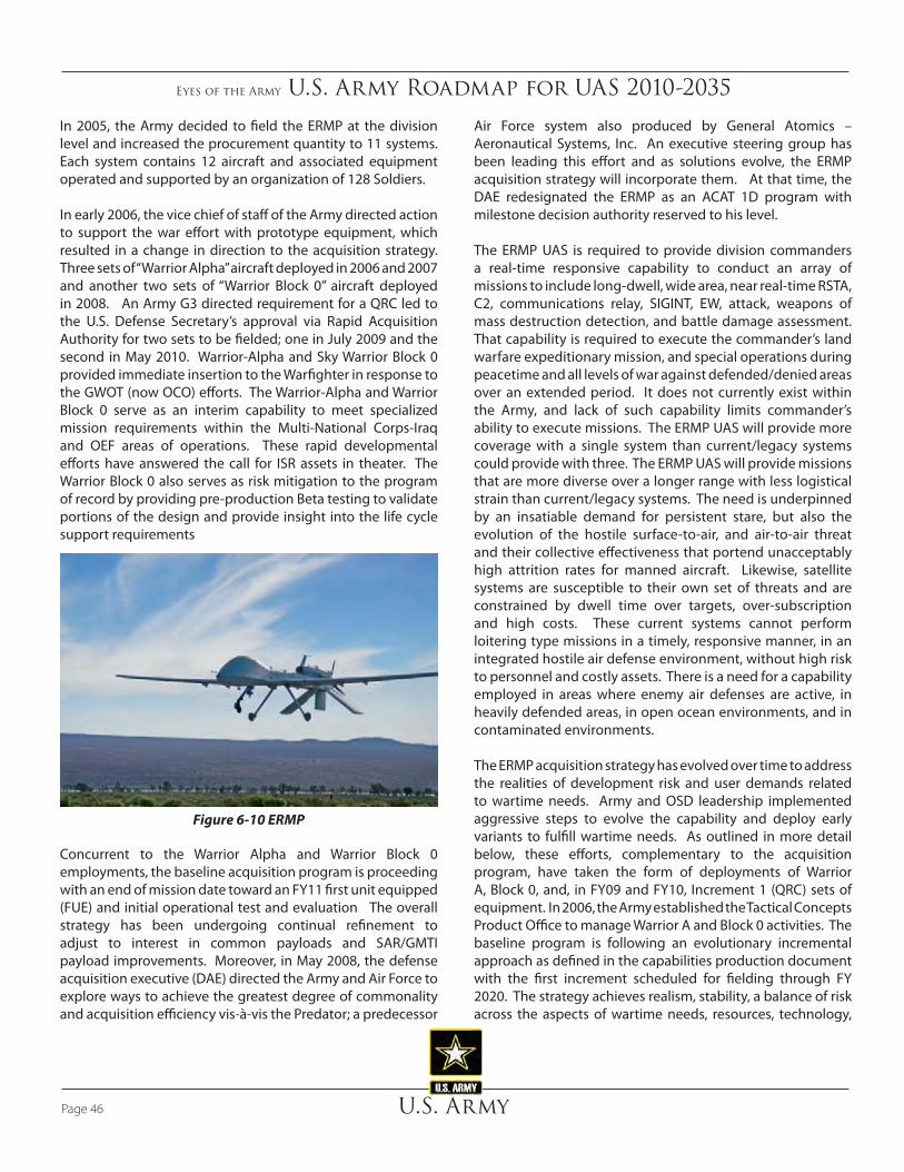
Eyes of the Army U.S. Army Roadmap for UAS 2010-2035
U.S. ArmyPage 46
Air Force system also produced by General Atomics – Aeronautical Systems, Inc. An executive steering group has been leading this effort and as solutions evolve, the ERMP acquisition strategy will incorporate them. At that time, the DAE redesignated the ERMP as an ACAT 1D program with milestone decision authority reserved to his level.
The ERMP UAS is required to provide division commanders a real-time responsive capability to conduct an array of missions to include long-dwell, wide area, near real-time RSTA, C2, communications relay, SIGINT, EW, attack, weapons of mass destruction detection, and battle damage assessment. That capability is required to execute the commander’s land warfare expeditionary mission, and special operations during peacetime and all levels of war against defended/denied areas over an extended period. It does not currently exist within the Army, and lack of such capability limits commander’s ability to execute missions. The ERMP UAS will provide more coverage with a single system than current/legacy systems could provide with three. The ERMP UAS will provide missions that are more diverse over a longer range with less logistical strain than current/legacy systems. The need is underpinned by an insatiable demand for persistent stare, but also the evolution of the hostile surface-to-air, and air-to-air threat and their collective effectiveness that portend unacceptably high attrition rates for manned aircraft. Likewise, satellite systems are susceptible to their own set of threats and are constrained by dwell time over targets, over-subscription and high costs. These current systems cannot perform loitering type missions in a timely, responsive manner, in an integrated hostile air defense environment, without high risk to personnel and costly assets. There is a need for a capability employed in areas where enemy air defenses are active, in heavily defended areas, in open ocean environments, and in contaminated environments.
The ERMP acquisition strategy has evolved over time to address the realities of development risk and user demands related to wartime needs. Army and OSD leadership implemented aggressive steps to evolve the capability and deploy early variants to fulfill wartime needs. As outlined in more detail below, these efforts, complementary to the acquisition program, have taken the form of deployments of Warrior A, Block 0, and, in FY09 and FY10, Increment 1 (QRC) sets of equipment. In 2006, the Army established the Tactical Concepts Product Office to manage Warrior A and Block 0 activities. The baseline program is following an evolutionary incremental approach as defined in the capabilities production document with the first increment scheduled for fielding through FY 2020. The strategy achieves realism, stability, a balance of risk across the aspects of wartime needs, resources, technology,
In 2005, the Army decided to field the ERMP at the division level and increased the procurement quantity to 11 systems. Each system contains 12 aircraft and associated equipment operated and supported by an organization of 128 Soldiers.
In early 2006, the vice chief of staff of the Army directed action to support the war effort with prototype equipment, which resulted in a change in direction to the acquisition strategy. Three sets of “Warrior Alpha” aircraft deployed in 2006 and 2007 and another two sets of “Warrior Block 0” aircraft deployed in 2008. An Army G3 directed requirement for a QRC led to the U.S. Defense Secretary’s approval via Rapid Acquisition Authority for two sets to be fielded; one in July 2009 and the second in May 2010. Warrior-Alpha and Sky Warrior Block 0 provided immediate insertion to the Warfighter in response to the GWOT (now OCO) efforts. The Warrior-Alpha and Warrior Block 0 serve as an interim capability to meet specialized mission requirements within the Multi-National Corps-Iraq and OEF areas of operations. These rapid developmental efforts have answered the call for ISR assets in theater. The Warrior Block 0 also serves as risk mitigation to the program of record by providing pre-production Beta testing to validate portions of the design and provide insight into the life cycle support requirements
Concurrent to the Warrior Alpha and Warrior Block 0 employments, the baseline acquisition program is proceeding with an end of mission date toward an FY11 first unit equipped (FUE) and initial operational test and evaluation The overall strategy has been undergoing continual refinement to adjust to interest in common payloads and SAR/GMTI payload improvements. Moreover, in May 2008, the defense acquisition executive (DAE) directed the Army and Air Force to explore ways to achieve the greatest degree of commonality and acquisition efficiency vis-à-vis the Predator; a predecessor
Figure 6-10 ERMP

Eyes of the Army U.S. Army Roadmap for UAS 2010-2035
U.S. Army Page 47
lead time realities, consideration of deployment data on Warrior A, Block 0 and QRC 1, the stability of the hardware, and the substantial costs of deferring that milestone
• A second decision point for LRIP 2 to distribute risk
• Baseline with a conservative software development schedule
• Earliest possible/incremental deployments
• Avoiding production gaps
Figure 6-11 depicts the near-term implementation plan. The PoR for the ERMP, Shadow, and Raven UAS are clearly defined and funded. The Hunter and GMAV are also fully funded and operationally deployed to support on-going combat
testing and training. In addition, the schedule and strategy offered flexibility in addressing program perturbations due to changing needs, sudden budget shortfalls, or development delays. It takes into account the realities of yearly funding availability and attempts to avoid fourth quarter contract awards that put funding at risk. Further, it acknowledges the investment and momentum already established with early deployments and strived to avoid substantial cost increases by minimizing production gaps and those associated costs and workforce interruptions. There are six key aspects to the program schedule:
• Distributed development and testing with a staggered concurrent software development plan to spread risk
• The LRIP 1 acknowledgement of the inherent risks with limited data, but balancing that against the production
Family of SUAS
MQ-5B ERMP(MQ-1C)Extended Range Multi-Purpose
Shadow Tactical UAS
I-GNAT
RQ-- 7A
RQ-7B
RQ-11B
RQ-5A
FY03 FY04 FY05 FY06 FY07 FY08 FY09 FY10 FY11 FY12 FY13 FY14 FY15RQ-11A
RQ-7C
Division and above: Long range and durationIntegrated, multi-echelon employmentRSTA, MUM, Attack, C2 Support , EA
IOC
IOC
S&T focus: Near Term- Improved Endurance/range- Precision engagements- Increased Payloads – multi-mission capability- Optionally piloted vehicle conceptsImproved Propulsion Systems
ERMP Incr II Requirements Dev
AH-64/OH-58D
UH-60/CH-47OPV S&T – Current Fleet – Demo/Exp
Battalion and below: Short duration, limited rangeStove-piped, small unit battlefield information
Brigade: Medium range and durationMulti-echelon planning/executionRSTA, MUM, Communications Relay
QRC(MQ-1C)
VTOL niche capability
ROVER
System RVTs Provides multi echelon SA OSRVT INC III
System GCSOSGCS
OGCS: Stove piped, UA specific ground control station
TCDL
UGCS
LOI 2 LOI 3LOI 1
UGCS: Controls Brigade and Division UAUA. “On the fly” UA switching
Enabled by Common Operator/Common Maintainer
MUM TBLK III AH 64D
UGV Integration
Figure 6-11 UAS Near-Term Implementation

Eyes of the Army U.S. Army Roadmap for UAS 2010-2035
U.S. ArmyPage 48
operations but are not formal PoRs. It is important to note that during the near-term parallel efforts continue with respect to the research, study, and experimentation for systems expected to emerge in the mid or far-terms. Work on the AoA continues to determine the way ahead for the next generation of the armed aerial scout (AAS). The Army will decide on the best course of action and whether the AAS will be fully manned, unmanned, or a mix of both options. Other areas that require intensive study and experimentation are micro-technology, SWARM, VTOL, increased autonomy/interoperability, OPV, and a sustainment/cargo UAS. The developmental process is a stair-stepped approach where the research, study, and experimentation serve as the foundation for advancements made in the mid-term. Developmental efforts conducted in the near-term transition to S&T work in the mid-term, and result in RDT&E advancements in the far-term.
Eyes of the Army U.S. Army Roadmap for UAS 2010-2035
U.S. Army Page 49
7. Mid-Term (2016-2025)The Army fully integrates UAS. The family of SUAS introduces organic and multiple UAS that are tailorable to specific mission requirements providing lower echelon commanders with increased SA. Each UAS operator equipped with the UGCS and trained to operate multiple types of UAS, integrate UAS capabilities at brigade through corps levels. The OSRVT, embedded throughout tactical formations provides a standardized platform that delivers accurate FMV from a variety of unmanned and manned platforms to the “decider forward.” The ERMP company achieves full operational capability (FOC) which provides the division commander with unprecedented SA and the ability to deliver effects across the division AO. The widespread introduction of OPV aircraft derived from the current flight of manned army helicopters facilitates increased aviation reconnaissance, attack, and support warfighter functions. Robust embedded simulation provides the foundation for affordable, effective individual and collective home station training. The S&T effort focuses on UAS commonality, integration, and interoperability with other Army and Joint platforms. Introduction of semi-autonomous characteristics and cognitive aiding software reduces user workload and increases effectiveness.
The UAS leadership needs materiel and personnel solutions to achieve the innovation enabled by the doctrine, organization, leadership and policy streamlining. Three critical elements– standardization of interfaces, open architecture, and
automation - form the nexus of this innovation. Standard interfaces between the vehicle and control station, and between the vehicle and payload, will free industry to develop the next generation systems and components needed to support the critical design review (CDR) as well as other government departments and agencies. Just as open architecture software exponentially advanced computer applications, UAS system interface standards will improve current UAS innovations. One of the highest impact areas for innovation is automation.
There are other interdependencies across the DOTMLPF-P spectrums that are critical to guide Army UAS development, acquisition, and fielding. Doctrine defining multi-role UAS allocation to support the CDR is critical to determine prioritization of capability development. Without a clear definition of requirements, the need for more of the capabilities that the UAS can provide are unending, thus trapping the Army into a reactive, rather than the deliberate planning, programming, budgeting and execution cycle. The UAS will never replace thinking, flexible, and prepared Soldiers. New and ongoing programs developing increased capabilities (both manned and unmanned) continue to provide cost-effective results. Concept demonstrations and prototype experimentation develop from successful technology demonstrations. Significantly, acquisition programs develop from successful prototype demonstrations. In the mid-term, Soldier worn systems like the Ground Soldier System (GSS) contain heads-up displays of UMS video and meta data, and a common controller with optional voice control. Future UAS must support rapid and fluid operations enhancing an increasingly net-centric force. Future UAS must be more accurate to increase target location accuracy, enable increased effects, and mitigate collateral damage.
Figure 7-1 depicts the Army’s mid-term prediction for how unmanned systems may expand into the conventional manned roles. UAS will conduct the large majority of the surveillance and C3 missions and approximately half of the attack and armed reconnaissance missions. The sustainment/cargo UAS role significantly matures and supports approximately 25% of the aerial logistical sustainment/cargo delivery requirements Army wide. Utility and MEDEVAC UAS predominately remain in developmental stages throughout the mid-term.
We begin to implement the Army UAS vision of operators simultaneously manipulating multiple UA platforms from a single crew station within a UGCS. The LOI 4 control of UAS from a manned aircraft improves MUM operations and extends the range of UAS. UAS disseminates sensor and mission results across multiple echelons via multiple means such as a
“Designing forces is not just about the number and types of units of employment. It is also about having processes in which the norm is creating new capabilities out of existing organizations, adapting methodologies in ways not previously envisioned and reshaping organizations – all at the speed of requirements.” Lieutenant General (Retired) James M. Dubik, The Magazine of the Association of the U.S. Army, September 2009

Eyes of the Army U.S. Army Roadmap for UAS 2010-2035
U.S. ArmyPage 50
common RVT or a robust digital network as depicted in Figure 7-2, Linking the Battlefield. Also envisioned in the mid-term is distributed LOI 3 sensor control from multiple sites. Ultimate control will remain with the crew in the controlling GCS or manned aircraft, but another control node gains remote sensor control.
7.1 UAS Mid-Term Capabilities
Technological advances developed in the near-term provide materiel advances in the mid-term through concept and technology demonstrations, including increased UAS autonomy, advances in propulsion (engine and power train), rotors and aeromechanical structures. Continued development in survivability, maintenance, aircraft performance (including range, lift, endurance and expansion of performance envelopes), mission equipment packages (including electronic attack, directed energy, and recently standardized munitions) additionally provide options for
both programs of record and newly emerging manned and unmanned platforms. During this period, advances in operations in degraded visual environments provide greater safety and survivability across the spectrum of aircraft operations. Applications of maintenance and reliability technology improvements to the fleet provide greater operational flexibility and efficient operations.
Through the mid-term, the Army begins fielding the future-armed aerial scout aircraft whether manned, unmanned, or a combination of both. This aircraft also is an advance in commonality in that it combines the reconnaissance and attack role into a single airframe. During this timeframe the Army also begins fielding a sustainment/cargo UAS. Research, experimentation, and development on advanced payload capabilities, and autonomy continues to expand capabilities for sustainment/cargo UAS.
During the mid-term, medical resupply operations mature with final operational testing and deployment of
UnmannedManned
Mid-Term
Surveillance
Armed Recon
Attack
Utility
C3 (Comms Ext)
Sustainment / Cargo
MEDEVAC
Missions
TimeKey
Manned - Unmanned Mix Transition
Figure 7-1 Mid-Term Manned-Unmanned Roles Transition

Eyes of the Army U.S. Army Roadmap for UAS 2010-2035
U.S. Army Page 51
platforms. Unmanned systems transport medical supplies throughout the battlefield across extended distances during this timeframe.
Research of patient monitoring, communication and environmental factors continues. Demonstrations of technologies facilitate unattended transport of selected categories of stabilized casualties from site of injury to forward surgical team level facilities by 2025. Ongoing work in the areas of remote intervention and tele-presence result in initial capability demonstrations for the unattended movement of critically wounded casualties. Compartment or cubed space design specifications accommodate securing the NATO standard litter and LSTAT. Demonstrations validate the use of external hoist capability to accommodate patient or Special Forces personnel extraction via UAS.
7.2 Mid-Term Army UAS Development Considerations
Full integration of all UAS programs of record into the Army characterizes the 2016-2025 timeframe. Also in the mid-term, the Army begins to achieve network centricity. The RQ-11 Raven, RQ-7 Shadow, MQ-1C fully deploy, while emerging vertical take-off and landing (VTOL) UAS reach full operational capability. Approximately 18-24 months prior to the start of this period, the Army will have completed a full capabilities-based assessment across the DOTMLPF-P domains to inform Army leadership, influence other decisions in DOTMLPF-P besides POM, such as Total Army Analysis, and direct Army investments.
Army UAS Operational View
Shadow PLT2 UGCS / 4 Shadow
Shadow PLT3 UGCS / 4 Shadow
CAB ERMP Co.5 UGCS / 12 ERMP
X
X
Fires
X
BfSB
X
BCT
18 DIVs
CAPABILITIES OF UGCS Provides CDR ability to control and receive data from multiple UA types Common Cockpit and Operating Software in a 5 ton and HMMWV Configuration Enables UGCS/OSRVT linked systems Provides Payload Products to the network for exploitation Maximizes 15W & 15E MOS training and simulation Provides tactical flexibility
LOI 2: Direct Receipt of Payload Product LOI 3: Payload Product Receipt / Payload Control LOI 4: Flight/Navigation Control LOI 5: Organic UA: Takeoff/Landing Control
UAS EMPLOYMENTReconnaissance, Surveillance and Target Acquisition,
MUM, Communication Relay, Attack, Sustainment/Cargo
Interfaces
Robotics
LOI 2: Direct Receipt of Payload Product LOI 3: Receipt of Product/Payload Control
CAPABILITIES OF OSRVT Provide LOI 2 and 3 capability at Soldier level – on the move Increases Tactical Commander’s SA of battlespace Provides UAS products at multi-level Allows Soldiers to mark and capture tactical information on
screen. Multiple configurations for tactical flexibility Correlated sensor data and map with metadata
MTADS Video
SoldierRaven, UGV,
g-MAV CC
Video Stream & Metadata Stream
OSRVT(2/BDE, 1/BN, 1/CO, (1/PLT*))
Mounted TOC
LOI 2-5 of U
A
ERMPShadow
Hunter
TCDL Equipped Unmanned Aircraft (UA)
LOI 2-4 of UA
AH-64DBlock II/III
EUH-60 A2C2S
Airborne UA Control
LOI 2-4 of UAACS
OH-58D
System Architecture
LOI 2-3 of UAMTADS Video
Figure 7-2 Linking the Battlefield
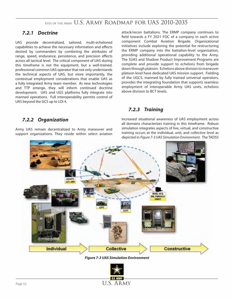
Eyes of the Army U.S. Army Roadmap for UAS 2010-2035
U.S. ArmyPage 52
7.2.1 Doctrine
UAS provide decentralized, tailored, multi-echeloned capabilities to achieve the necessary information and effects desired by commanders by combining the attributes of range, speed, endurance, persistence, and precision effects across all tactical level. The critical component of UAS during this timeframe is not the equipment, but a well-trained, professional common UAS operator that not only understands the technical aspects of UAS, but more importantly, the contextual employment considerations that enable UAS as a fully integrated Army team member. As new technologies and TTP emerge, they will inform continued doctrine development. UAS and UGS platforms fully integrate into manned operations. Full interoperability permits control of UAS beyond the GCS up to LOI 4.
7.2.2 Organization
Army UAS remain decentralized to Army maneuver and support organizations. They reside within select aviation
attack/recon battalions. The ERMP company continues to field towards a FY 2021 FOC of a company in each active component Combat Aviation Brigade. Organizational initiatives include exploring the potential for restructuring the ERMP company into the battalion-level organization, providing additional operational capability to the Army. The SUAS and Shadow Product Improvement Programs are complete and provide support to echelons from brigade down through platoon. Echelons above division to maneuver platoon level have dedicated UAS mission support. Fielding of the UGCS, manned by fully trained universal operators, provides the integrating foundation that supports seamless employment of interoperable Army UAS units, echelons above division to BCT levels.
7.2.3 Training
Increased situational awareness of UAS employment across all domains characterizes training in this timeframe. Robust simulation integrates aspects of live, virtual, and constructive training occurs at the individual, unit, and collective level as depicted in Figure 7-3 UAS Simulation Environment. The TADSS
Figure 7-3 UAS Simulation Environment

Eyes of the Army U.S. Army Roadmap for UAS 2010-2035
U.S. Army Page 53
replicate all payloads and mission sets. The UAS simulators link to other aviation and combined arms devices to fully operationally integrate UAS capabilities into all formation’s training needs.
The Aviation CoE, Directorate of Training and Doctrine UAS Training Strategy continues to evolve UAS training strategies. The ultimate training goal is to have the ability to fly live training sets at each home station or regional locations, while using simulations to bridge the resource and training opportunity gaps. Institutional, operational, and self-development training is closely nested with each other in order to provide the most highly trained UAS operators, staff officers, and leaders possible. As UAS capabilities, technology, and mission functions continue to grow throughout the next 25 years, the Army must fully embrace all UAS training opportunities in order to harness their full capabilities.
During the mid-term, the Maneuver CoE creates an Unmanned Systems University at Fort Benning to advance SUAS, OSRVT, UGV, and UGS training. The goal is to establish a Master Training course that utilizes web based home station training to reduce the time a Soldier spends away from his unit and family.
7.2.4 Materiel
Demonstrations of emerging technologies and their applications provide Warfighters a real and current insight into future UAS possibilities. These demonstrations, and prototype experimentation, enable greater cooperation between the technology base and the combat developers in an environment that facilitates more rapid acceptance and transition.
The community moves closer to U.S. Government owned technical data packages for acquisition systems, enabling the establishment of standards that are the foundation of interoperability and commonality.
Development of aviation specific technologies that include rotors, drive trains and propulsion, vehicle management, modular and integrated survivability enhancements, and reliability-centered maintenance continues in the timeframe. Aircraft autonomous systems and SAA solutions occur.
Similar to near-term capabilities, OSRVT expands the availability of UAS FMV and significantly increases air-ground interoperability. Improvements of OSRVT Increment II in
this period should provide the OSRVT operator with a fully encrypted capability to execute up to LOI 4 with multiple UAS that will result in a significant increase in responsiveness to the ground force. The OSRVT operator can control the UA in a defined safety box established and maintained by the UAS operator. This concept is essential to expanding UAS coverage through fewer GCS (multi-aircraft control) and fewer operators per number of aircraft. LOI 4 will eventually include MUM in the same flight.
The TCDL is the standard digital foundation for networked integration of all Group 3 UAS and above. It provides Level 1 encryption, commonality of command and control, and simplifies distribution. All SUAS and ground robotics will incorporate the DDL network. By adding DDL, it will allow OSRVT to use one antenna that will reduce the size, weight, and enable GSS. The OSRVT Increment 2 allows up to LOI 3, facilitates unprecedented information access for ground commanders, aviation, other combined arms, and intelligence MUM joint teams. The result not only reduces the sensor-to-shooter timeline, but redefines the entire targeting process. All OSRVT equipped aircraft allow LOI 3 control from manned aviation platforms.
Mid-term fleet of manned aircraft integrates optionally piloted vehicle capability to increase coverage in reconnaissance role and increase supportability hours without increasing manned flight hour requirements.
Development continues on small multi-purpose precision munitions. Completion of initial integration with legacy platforms, manned and unmanned, for demonstration and possible fielding with operational forces occurs during this period.
Demonstrations of cognitive aid software continue through concept and technology demonstrations. Mission planning, airspace deconfliction, dynamic retasking and engagements, data access and real time mission assistance are areas of investigation and should begin showing results during this timeframe.
The UAS maintenance community continues to mature in the mid-term. Warrant officers and non-commissioned officers remain in specific UAS maintenance MOS to provide a vast knowledge base and experience level. All UAS maintenance courses produce the requisite number of UAS maintainers. The ERMP maintenance transitions from a PBL system to an Army self-sustained program with continued FSR specialty support. The remaining programs of record continue to use the field and sustainment levels of maintenance.

Eyes of the Army U.S. Army Roadmap for UAS 2010-2035
U.S. ArmyPage 54
The Army incorporates CBM within the larger programs of record (ERMP and Shadow). SWaP capabilities improve, which allow the Army to install HUMS on each of the UAS platforms. The HUMS allow maintainers to monitor component performance and to anticipate pending failures. CBM will save time and money expended on maintenance because maintainers can focus on actual failures instead of performing time-scheduled maintenance. The common logistics-operating environment emerges and provides commanders with real time system status feedback, via a dashboard update.
UAS and other Army systems are migrating to CBM using real-time data to prioritize and optimize maintenance resources. It replaces maintenance based on repair after a part has failed or fixed-time parts replacement based on a rigid maintenance schedule rather than the actual condition of the part. Condition monitoring determines the equipment’s health and provides the time required maintenance is necessary. Instrumentation of equipment allows maintenance personnel to decide when to perform maintenance on equipment. Ideally, CBM allows personnel to complete the correct maintenance and repairs, thereby minimizing spare parts costs, system downtime, and maintenance time.
Despite its usefulness, there are several challenges to the use of CBM. First and most important, the initial cost of CBM is high. It requires improved instrumentation of the equipment. Therefore, it is important for the installer to decide the importance of the investment before adding CBM to all equipment. Second, introducing CBM will invoke a major change in the performance of maintenance, and potentially to the whole maintenance organization in a company. Measuring equipment by simple values such as vibration (displacement or acceleration), temperature or pressure, it is not trivial to turn this measured data into actionable knowledge about health of the equipment.
7.2.5 Leadership
Increased sensor capabilities, coupled with aircraft capable of ranging the tactical area of operations for long periods, provide Army leaders and Soldiers flexibility when conducting operations in a complex operating environment. Unmanned aircraft systems reduce, but do not eliminate the hallmark of military operations - uncertainty.
We can expect enemy forces to target UAS capabilities as UAS effectiveness becomes clear. Enemy will develop TTP to attack ground facilities, communications and control links,
and airborne aircraft. Additionally, our leaders must expect increased enemy efforts to decoy and camouflage, thus limiting UAS intelligence.
Technological advances enable OPV and increased UAS autonomy, but these technological advances do not replace thinking leaders capable of dealing with a wide variety of threats spread across the spectrum of operations. UAS employment training must increase in officer and NCO leadership development courses at all levels. In the mid-term, the Army should establish a commissioned officer UAS career track or an additional skill identifier.
7.2.6 Personnel
Institutional training produces fully trained and professional common UAS operators who are capable of supporting Army and Joint missions. The 15W, 15E, and 150U career fields increase significantly throughout the mid-term as UAS fieldings continue and OPV approach 50 percent of aviation assets. The BCT and below table of organization and equipment (TOE) must include a robotics/NCO operator. Operators are capable of employing multiple UAS, varied sensors, and mission equipment packages from a single control station in support of a wide variety of missions. The UAS missions will be in coordination and integrated with intelligence analysts seeking specific, detailed information. By the end of the mid-term, UAS MOS growth will reach steady state based upon the current approved and projected fielding plans. Populations will mature, in terms of having sufficient senior grade non-commissioned officers and senior warrant officers that have developed within their specific career field.
7.2.7 Facilities
Unmanned aircraft systems will have airworthiness certification, probably by UAS groups, which will increasingly include the FAA sense and avoid improvements for flying in the NAS. The UAS will assist in disaster relief, humanitarian support, and homeland defense. Training areas will be more widely available and integrated into the NAS. Facility costs decrease for new fielding as UAS and OPV share airfields with manned systems and, in some cases, replace manned systems on the flight line.

Eyes of the Army U.S. Army Roadmap for UAS 2010-2035
U.S. Army Page 55
7.2.8 Policy
Policy issues in the mid-term include:
• Develop policy for Joint CONOPs and Army TTP redefining Joint tactical air controller involvement for munitions delivery from Army UAS
• Develop counter UAS doctrine to enemy use of reconnaissance and lethal UAS.
• Develop policy to allow casualty evacuation (CASEVAC) with UAS or OPV
• Develop policy to allow OPV transport of Soldiers
• Develop policy for Joint CONOPs and Army TTP for use of sustainment/cargo UAS
7.3 UAS Mid-Term Implementation Plan
Advanced airframes, propulsion, and flight controls will enable UAS operations in weather conditions currently requiring mission abort. UAS will make full use of embedded diagnostics and prognostics and will be fully capable of platform self-diagnostics and infrastructure interaction for system health management in a common logistics-operating environment.
As a minimum, the UAS should provide:
• Overall operational status
• Consumption status (fuel and ammunition),
• Equipment health
− System status, including critical and predicted faults
− Diagnostic status – actual and predicted
− Other faults requiring attention
Autonomy for a system-of-systems is a revolutionary concept that can advance through rapid innovation. This aspect of mid-term actions is broken out separately since all follow-on actions hinge upon this. The manufacturer may have problems making required changes to the operating system
to advance autonomy while meeting program performance requirements. The initial programmatic method to advance innovation is to facilitate competition on system components by defining standards. Through the definition of standard interfaces and modular systems designed for innovation, autonomy can be incrementally integrated and refined throughout the process.
System upgrades in the mid-term include:
• ERMP: The ERMP will add a capability for operations from generalized sites, with the ability to refuel and re-arm at impromptu sites. The selection of available weapons will widen and include a small semi-active laser weapon suitable for small, soft targets in sensitive collateral damage areas. The weapon selection and tactics also enable EW, EA, and air defense suppression capabilities. All sensing, both from imaging payloads (EO/IR, SAR/MTI), and non-imaging payloads (SIGINT) will be fully cross-correlated with robust slew to cue functionality shared throughout the system. The ERMP will support multiple payloads. The enhancement of ERMP’s first generation communications relay capability will support Joint and coalition Internet protocol (IP) based networking across division-sized areas of operations. The ERMP will be able to support targeting for coordinate seeking weapons through target location accuracy upgrades to the common sensor payload and geo-registration via Heterogeneous Airborne Reconnaissance Teams (HART) technology.
• Shadow: The RQ-7C Product Improvement Program (PIP) ensures that the Shadow UAS remains the Army’s tactical “workhorse” that supports Brigade Combat Team (BCT) operations. As a fully integrated, organic asset, the RQ-7C provides the ground commander with tactically significant situational awareness and the ability to influence operations in a timely manner. The Shadow PoR continues to seek improved capabilities to meet emerging requirements driven by evolving tactical demands. Product improvements such as increased endurance, range, heavy fuel engine, payload capacity, and improved system reliability ensures that the RQ-7C remains one of the Army’s primary UAS systems. Additionally, improvements will be made in terms of commonality of components and interoperability with the UGCS and OSRVT.

Eyes of the Army U.S. Army Roadmap for UAS 2010-2035
U.S. ArmyPage 56
• SUAS: In the mid-term, the Raven UAS PIP ensures that the latest technology and up-to-date capabilities fielded to support the tactical commanders. In addition to the Raven PoR, a family of small UAS emerges to provide a greater range of capabilities.
• Control Element: During the mid-term, interoperability improvements facilitate the transition from an OSGCS to a universal system, thereby allowing a UAS operator to control more than one aircraft. Interoperability improvements to the OSRVT will provide level III control that will allow users to control the UA payloads from somewhere other than the ground control station.
Figure 7-4 depicts the mid-term implementation plan. Historically, the U.S. Army has been plagued with supporting extended lines of communication and resupply lines due to austere locations, environmental conditions and rugged terrain. To date, there has been very limited use of an unmanned sustainment system to resupply forward deployed units. Manned aviation sustainment platforms will remain the primary airborne heavy-lift means for the near future; however, sustainment/cargo UAS capabilities will augment the formidable logistics requirements of enhanced Army and JIM operations through optionally manned aircraft or logistics UAS. The near-term emerging requirement that identified the advantages of sustainment/cargo UAS or OPV will define the RDT&E to begin development and testing for fielding.
Family of SUAS
MQ-5B ERMP(MQ-1C)Extended Range Multi-Purpose
FY16 FY17 FY18 FY19 FY20 FY21 FY22 FY23 FY24 FY25
FOC
IOC FOC
S&T focus:
FOC
ERMP Inc II – Family of UASERMP Inc II Materiel Dev
- Increased Commonality: airframes, control stations, payloads, power sources- Cognitive Aiding Software- Survivable: on-board and “swarm” ASE- Lethal/Non-Lethal Payloads- All weather capability - Fully compliant sense and avoid
AH-64/OH-58D
UH-60/CH-47OPV S&T
Universal Ground Control Station + Universal OperatorsExtensive simulation training enabled = ARFORGEN-balanced UAS force structure
Cargo and/or Recon OPV capability
OSRVT
UGCS is backbone of an integrated network that permits accessto multiple UA’s operating across the area of operations. Enabled by a complex, individual and collective training simulation environment. User receives the mission package effects, UA type Is of little importance to the “customer.”
LOI 4
(Phased out of Inventory)
Shadow Tactical UASRQ-7C
RQ-X Requirements Dev
Nano UAS
TCDLUGCS
Figure 7-4 UAS Mid-Term Implementation
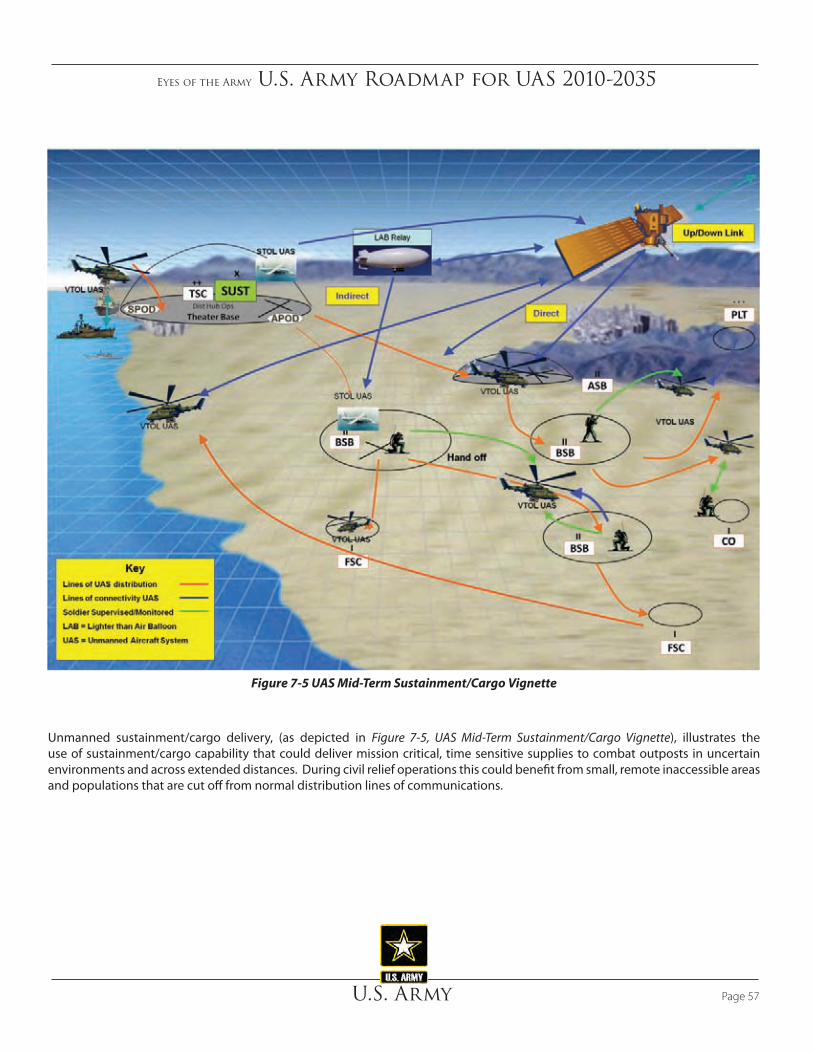
Eyes of the Army U.S. Army Roadmap for UAS 2010-2035
U.S. Army Page 57
Figure 7-5 UAS Mid-Term Sustainment/Cargo Vignette
Unmanned sustainment/cargo delivery, (as depicted in Figure 7-5, UAS Mid-Term Sustainment/Cargo Vignette), illustrates the use of sustainment/cargo capability that could deliver mission critical, time sensitive supplies to combat outposts in uncertain environments and across extended distances. During civil relief operations this could benefit from small, remote inaccessible areas and populations that are cut off from normal distribution lines of communications.

Eyes of the Army U.S. Army Roadmap for UAS 2010-2035
U.S. ArmyPage 58
Figure 7-6 UAS Nano Vignette
In the mid-term, Nano UAS, depicted in Figure 7-6, will reconnoiter the interior of structures prior to Soldiers entering. Nanos will be controlled by small handheld or Soldier worn devices and possess collision avoidance to negotiate confined spaces. As technology matures, Nanos will be capable of conducting surveillance for an extended timeframe by lying dormant to conserve power or perch on power lines to draw needed energy.
Eyes of the Army U.S. Army Roadmap for UAS 2010-2035
U.S. Army Page 59
8. Far-Term (2026-2035)System survivability, footprint, autonomy, commonality and interoperability, and open systems architecture are the major areas of concern in the far-term. Specific areas include platforms and performance; control station complexity; data link security, throughput, and product dissemination; sensor and mission equipment packages size, weight, power and capability; and operator training and qualifications. The USAACE, in conjunction with Aviation and Missile Research, Development and Engineering Center and UAS partners across the Army and Joint community, identify and prioritize enablers to bridge these and future identified gaps. The Army S&T process supports the future vision by addressing and reducing these gaps in order to provide the technological support to fortify the overall Army missions.
At the small unit level, introduction of Nano technology, improved sensors, extended station time and networked system significantly increases the commander’s SA. The overall integration of UAS into a networked, semi-autonomous system of systems results in the ability to achieve the desired effect regardless of the echelon executing operations. The UAS providing the “product” is transparent to the user. Extensive cognitive aiding software, tailorable multi-mission capable payloads and semi-autonomous UAS behavior combine to meet the anticipated aviation mission sets of the future. The Army UAS continues the integration process into Joint operations while Joint UAS capabilities are fully available to Army commanders. Man-in-the-loop, located in future command post plan and integrated UAS effects rather than focus on specific UAS.
Figure 8-1 depicts the Army’s far-term vision, with respect to UAS integration into the traditional manned roles. Similar to the mid-term, UAS conduct nearly all of the surveillance and C3 roles. UAS predominately conduct armed reconnaissance, attack, and sustainment/cargo missions
while manned platforms support approximately 75% of the mission load. The majority of utility and MEDEVAC roles remain manned but start to transition to unmanned capabilities late in the far-term.
8.1 UAS Far-Term Capabilities
In the far-term, UAS will exhibit substantially increased performance and capability. Capabilities will increase while size and weight continue to decrease, providing significantly greater capabilities in much smaller packages. Far-term capabilities discussed below in conceptual terms have not fully emerged.
• Increased all weather capability to permit operations in severe icing, turbulence, wind, precipitation, and reduced visibility, including sensor capabilities to operate in those conditions
• Fully compliant SAA capabilities and seamless national airspace integration
• Increased autonomy will significantly reduce operator workload, increase reliability and speed of mission performance, reduce demands upon bandwidth or allow more capability with the same bandwidth, and deliver integrated capabilities such as smart warfighting array of reconfigurable modules (SWARM) and other teaming capabilities
• Improved rotorcraft will close the performance and airworthiness gaps with fixed wing systems and manifest higher reliability and lower cost of operation
• Increased efficiencies in flight and operations will continue to enlarge the flight regimes and utility of UAS to include such capabilities as transport of high value payloads and forward area aircraft refueling and servicing
• Sustainment/cargo delivery in most scenarios will be by unmanned sustainment/cargo aircraft and UGV.
• Improved versatility will result in multi-purpose and multi-role aircraft and payloads with operational utility decided at the point of launch rather than by class or model of aircraft
“Each generation goes further than the generation preceding it because it stands on the shoulders of that generation. You will have opportunities beyond anything we’ve ever known.”
President Ronald W. Reagan

Eyes of the Army U.S. Army Roadmap for UAS 2010-2035
U.S. ArmyPage 60
8.2 Far-Term Army UAS Development Considerations
The 2026-2035 timeframe produces common manned and unmanned systems. This requires a substantial increase in capability of both manned and unmanned systems. Technologies should merge commonalities of the systems that increase endurance and carrying capacity while decreasing SWaP requirements. The VTOL technologies will close the performance and airworthiness gaps with fixed wing systems, including rotor, propulsion, airframe and hybrid configurations providing point-to-point capability. Future expeditionary operational environments will require increased aviation support including all weather capability, fully compliant SAA capabilities, seamless national airspace integration, universal commonality, and integrated capabilities such as SWARM and other teaming capabilities. In SWARM, the UAS operate as a group, functioning together as a swarm of aircraft. The model requires the vehicles to function as individual units while being
part of a larger functioning organization operating to achieve a common mission goal. Technical research expanding the barriers to more efficient flight and operations must continue to enlarge the flight regimes and expeditionary utility of unmanned aircraft systems. This includes delivery of supplies or retrograde of high value payloads, high reliability and low cost of operation propulsion, operations in extreme conditions, reduced or zero visibility, improved data throughput, autonomous operations, and reduced footprint including forward area aircraft refueling and servicing, system hardware and operator personnel. Human factors considerations and advances in autonomous operations and employment will off-load the majority of the workload from the operator to the platform, supporting near-hands-off operations. Capabilities will increase while size and weight continue to decrease, thus providing significantly greater capabilities in a much smaller package. Offensive operations, in the far-term, become more automated leaving the fire decision in the control of the operator. Multi-purpose and multi-role aircraft and payloads will be standard with operational utility decided at the point of
UnmannedManned
Far -Term
Surveillance
Armed Recon
Attack
Utility
C3 (Comms Ext)
Sustainment / Cargo
MEDEVAC
Missions
TimeKey
Manned - Unmanned Mix Transition
Figure 8-1 Far-Term Manned-Unmanned Roles Transition

Eyes of the Army U.S. Army Roadmap for UAS 2010-2035
U.S. Army Page 61
launch rather than by class or model of aircraft. Sustainment/cargo UAS delivery in many scenarios will reduce the risk and uncertainty within the operational environment and provide sustainment across extended distances.
8.2.1 Doctrine
In the far-term, Army aviation doctrine fully integrates network centric operations that make possible full exploitation of increasingly autonomous UAS. Either UAS operate autonomously or accompany manned aviation in support of ground forces across the full spectrum of operations. Unmanned aircraft systems only and MUM are the standard for almost all aviation operations with manned aircraft capable of controlling (LOI 4) multiple UAS. Manned-only missions are rare and normally undesirable where any threat is expected. The battle command system embeds detailed UAS pre-mission planning using integrated cognition aided capabilities to reduce human workload and improve UAS effectiveness. Autonomous UAS operations provided with network optimization and self-healing capabilities characterize C2 support. The UAS support command and control requirements through network extension, thickening, and specific mission point-to-point voice and data integration.
The OPV concept combines the best of manned and unmanned aircraft capabilities. One concept for OPV is a toggle switch that has three positions: “2” for two pilots, “1” for one pilot, and “0” for unmanned. The OPV permit increased aviation operations with emergency or routine logistics resupply, medical evacuation, troop transport and autonomous/smart wingmen during operations. OPV allow the Army to increase the OPTEMPO on the UAS fleet and maximize Soldier effectiveness and efficiencies. In cases where operations are too dangerous for manned aircraft or extended performance is required, the aircraft will maneuver from a remote ground control station or another aircraft in the unmanned mode. The OPV system will be compatible with NATO STANAG 4586 making it compatible with other existing unmanned systems. System Life Extension Program will convert some manned assets as OPV aircraft thereby reducing development and operational costs of the UAS force.
Armed Scout UAS work with OPV AH-64, Shadow, and ERMP to provide multi-echeloned responsive time sensitive precision lethal and non-lethal effects throughout the AO. The division staff uses cognitive aides and planning software to optimize UAS employment as part of combined arms operations. Software supports intelligent access to huge amounts of collected UAS
sensor data and assists in rapid or long-term data exploitation or intelligence development. The OSRVT Increment III (HART) provides LOI 4 across the force. This provides access to real-time intelligence collection assets through simple requests. The Soldier or commander can electronically submit a request for information and the networked aviation assets respond with most effective mix of MUM assets based on planning and emerging mission requirements. The requestor also could add ‘trip wires’ that would deliver products when the trip wire was activated. For example, if the requestor adds a trip wire to watch a location for motion, the system alerts the requestor upon motion sensing and provides applicable FMV products. The OSRVT Increment III facilitates integration of UAS information across, up, and down echelons providing the foundation for a seamless COP. UAS will possess self-ASE to support operations in mid-high threat ADA environment.
Doctrine must account for specialized or modified UAS provide to less sophisticated allies or surrogates (that can multiply U.S. force projection). These alternative UAS systems would probably best be purpose-designed and purpose-built to cope with factors such as operator proficiency, environment of the particular theater of operations and the potential need to turn off any systems that fall into enemy hands. Such systems may or may not tie well into the nominal set of U.S. Army systems. Doctrine will evolve with the use of far-term systems that go beyond aerial vehicles. The subject systems include unattended, autonomous sensor-packages could act as trip wire devices and/or serve to verify aerial-sensed clues. In addition, strap-on payloads and data derived from image-recognition software will grow the array of inputs for operator consideration. Specialized training for operators could lead to synergistic benefits of human-machine teaming based on this growing array of system elements. Self-sufficiency in operations and the attendant logistics may be crucial for a future with constrained national resources and the consequential loss of overseas bases. System logic and modes of operation may have to deal with an unpredictable loss of various assets that range from aerial platforms to ground stations. Some level of system-wide, dynamic reconfiguration of C4I may be essential if logistics bottlenecks and delays are unavoidable.
8.2.2 Organization
Army UAS are decentralized to maneuver and support organizations. Shadow and ERMP organizations continue to evolve with manpower adjustments and equipment modernization efforts new operational concepts may drive

Eyes of the Army U.S. Army Roadmap for UAS 2010-2035
U.S. ArmyPage 62
organizational changes across the Army, to include UAS. The family of SUAS remains integrated in most formations. The OSRVT Increment III facilitates integration of UAS information across/up/down echelons providing the foundation for seamless COP.
8.2.3 Training
Universal UAS operators train and operate all Army UAS larger than SUAS using UGCS control. The UGCS will evolve into a software suite resident on the selected Army Battle Command System. The majority of UAS training is high fidelity, networked simulation that supports individual operator requirements, UAS mission crew requirements and collective supported unit training. Maintenance training is performed on simulation mock-ups and interactive 3-D software-based training that together satisfy hands on and cognitive training requirements. Continental U.S. airspace constraints compel commanders to rely on simulations augmented by live flight training at home station, regional facilities, or CTCs.
Leader training requires understanding and use of cognitive aid programs that support pre-mission planning and mission execution.
8.2.4 Materiel
The OSRVT Increment III provides LOI 4 across the force. Unmanned aircraft systems are equipped with aviation survivability equipment (ASE) to support operations in mid-high threat air defense artillery (ADA) environment. Integration of the OSRVT Increment III into the battle command system results in a net centric force.
Characteristics of far-term UAS:
• Optionally piloted vehicles
• Survivable in multiple environments
• Semi-autonomous/limited autonomous operations
• Networked force
• Extensive use of cognitive software to optimize systems employment
• MUM with air/ground systems
• Uplink/downlinks fully encrypted
• Fully integrated into PBL concept with onboard prognostic and diagnostic sensors
• Multi-functional sensors onboard single UA or networked sensors that provide cross-cued sensor data
System Life Extension Program and Product Improvements:
a. AH-64/Aerial Scout/UH-60/CH-47 optionally piloted
• Modernized target acquisition designation upgrade to UAS sensor software
• Added SAA sensors
• Degraded Visual Environment (DVE) sensors
• Engagement sensors
• Logistics sling loads / pods
b. ERMP Increment II
• Increased endurance
• Integrated ASE
• Non-lethal / lethal options expanded
• Reduced runway requirements
• VTOL technology
c. Shadow
• Armed with lethal / non-lethal effects
New starts:
• Armed Scout VTOL UAS or OPV
• Provide horizontal view
• On board munitions
• Smart wing man
• Multi-sensored

Eyes of the Army U.S. Army Roadmap for UAS 2010-2035
U.S. Army Page 63
− CBRNE
− Explosive hazards
− Semi-autonomous reconnaissance and security
• Sustainment/cargo UAS PIP
• UGCS
− Autonomy
− Multiple UAS control
• Capabilities translated into TOCs
Conditioned based maintenance fully integrates with most Group 3 and above UAS outfitted with HUMS. The UAS maintenance remains a Soldier responsibility with FSR support. Far-term maintenance percentages continue to be an 80 percent green suit and 20 percent contractor mix. Commonality and improvements to unit level logistic system- aviation equipment (ULLS-AE) or a similar system improve maintenance efficiencies.
8.2.5 Leadership
Fully trained aviation officers and warrant officers plan and execute manned and UAS missions as part of combined arms teams.
8.2.6 Personnel
The UAS populations will continue to mature across all grade levels throughout the far-term. The MOS strengths will expand, as necessary, to meet projected additional UAS fieldings. Material and software advances may facilitate increased UAS autonomy and capabilities, which may reduce the overall ratio of operators required per unmanned aerial vehicle. Officer, warrant officer, and NCO career paths support training in cognitive aid software required to maximize UAS effectiveness.
8.2.7 Facilities
Specialized facilities for training in counter-UAS environments provide realistic opportunities for developing and testing new
concepts and TTP as the NAS fully integrates UAS. The Army completes appropriate facility construction as they field UAS across active, reserve, and National Guard units.
8.2.8 Policy
Policy for the use and employment of Army unmanned aircraft systems must shape their increased utilization in all aspects of tactical and strategic operations. As systems become both widespread and intuitive, the force will rely more heavily on UAS at all levels of operations.
The challenge for this period will be three fold:
• As technology accelerates it will be incumbent upon both materiel and combat developers to ensure that forces are equipped and trained with the most current capabilities, some of which may not have apparent advantages prior to hardware demonstrations
• In order to ensure the developer communities continue to strive for achievable capabilities there must be an appreciation of the limits of technology and technology application. UAS developers must continue to leverage emerging technologies to field systems with greater capabilities.
• Unmanned systems are only as capable as their human operators. This human dimension of unmanned systems employment will become increasingly important as systems become more capable and simpler to use. It is widely accepted that weapons release will always have a human decision maker responsible for the judgment of the engagement. In addition, it is critical to scrutinize the breadth and scope of broadcast information to ensure the transmission of only necessary information to units without providing information overload. It is this aspect of unmanned systems employment, the crucial human link, which is currently an emerging field and will become critically important in the future.
UAS will have airworthiness certification for Level 2 that will include the FAA sense and avoid improvements for flying in the NAS. The UAS will assist in disaster relief, humanitarian support, and homeland defense. Training areas will be more widely available and integrated into the NAS.

Eyes of the Army U.S. Army Roadmap for UAS 2010-2035
U.S. ArmyPage 64
8.3 UAS Far-Term Implementation Plan
Like manned aircraft, defensive measures (low observable technologies, expanded flight envelopes, increased standoff, and countermeasures) provide for survivability and extended utility. Depicted in Figure 8-2 is the far-term implementation plan. The UAS include the family of SUAS, RQ-7C Shadow, MQ-1C (ERMP), OPV, and new starts. Offensive capabilities (air-to-air and air-to-ground weapons, developing non-lethal means, and advanced flight controls) provide for multi-role applications, in modes of use just now appreciated.
The path toward autonomous capability links depends upon DOTMLPF-P actions to integrate UAS with all other assets worldwide. These entail full integration with all airborne traffic in the NAS and international civil airspace through technology, procedural, training, and policy changes. The
UAS will fly formations with manned and unmanned aircraft as required by the operation. These changes will establish optimum networked basing, software that performs automatic processing, analysis, and dissemination to move from collecting information to knowledge.
The same technologies that keep UAS from any airborne collision will enable UAS formation flight. Coordinated missions and cooperative target engagement will provide the same mission efficiencies as manned aircraft.
The actions to gain unfettered airspace access and fly in formation will greatly expand the level of information collected. Automated TPED will optimize tasking of multiple assets to meet real-time collection needs while providing a means to analyze a greater portion of the data and imagery collected. Further, analysts will be able to synthesize more information into collective knowledge. Future analysis should use archived collected imagery.
Family of SUAS
- Autonomous Behavior- Swarming; other teaming capabilities- Self-healing network
S&T focus:
FY26 FY27 FY28 FY29 FY30 FY31 FY32 FY33 FY34 FY35
RQ-X
ERMP Family of UAS (Fixed Wing/VTOL)
UAS System of Systems
Attributes• NET CENTRIC CAPABILITY WITH ROBUST INFO SHARING• WIN-T AERIAL TRANSPORT SUPPORT• ARMED CAPABILITY• AIR OR GROUND MUM TEAMING• DYNAMIC RETASKING• PERFORM RAPID, AUTOMATED, LOGISTICAL MOVEMENT
OF MEDIUM WEIGHT, MODULAR PAYLOADS • CONDUCT OPERATIONS IN DEGRADED VISUAL
ENVIRONMENT WITHOUT RISK OF INADVERTENT CONTACT WITH THE GROUND OR FLIGHT PATH OBSTACLES
UAS System of Systems
OPV Capability
Nano UAS
- Common Datalink- Open Architecture
TCDL
UGCS
Figure 8-2 UAS Far-Term Implementation

Eyes of the Army U.S. Army Roadmap for UAS 2010-2035
U.S. Army Page 65
The final portfolio step leverages a fully autonomous capability and SWARM to put the enemy off balance by being able to create effects throughout the battlespace. Technologies to perform auto air refueling, automated maintenance, automatic target engagement, and SWARM would drive changes across the DOTMLPF-P spectrum. The result would be a revolution in the roles of humans in air warfare.
By 2025, Nanos will collaborate with one another to create swarms of Nanos (Figure 8-3) that can cover large outdoor and indoor areas. The swarms will have a level of autonomy and self-awareness that will allow them to shift formations in order to maximize coverage and cover down on dead spots. Nanos will possess the ability to fly, crawl, adjust their positions, and navigate increasingly confined spaces.
Technological advances in artificial intelligence will enable UAS to make and execute complex decisions required in this phase of autonomy, assuming legal and policy decisions authorize these advances. Today target recognition technology usually relies on matching specific sensor information with predictive templates of the intended target. As the number of types of targets and environmental factors increase, the complexity and time to complete the targeting increases. Further, many targeting algorithms are focused on
military equipment. Our enemies today and those we face in the future will find ways to counter our systems. Autonomous targeting systems, to include facial recognition, must be capable of learning and exercising a spectrum of missions useful to the Joint Warfighter. However, humans will retain the ability to change the level of autonomy as appropriate for the type or phase of mission.
Today flight control software has demonstrated the first stages of self healing by isolating malfunctions during self test and at times, compensating for loss of aircraft wing or tail surfaces. Also today, machines, not manual labor, accomplish stealth surface repair. As technology advances, machines will automatically perform some repairs in flight and conduct routine ground maintenance without human touch. There will be cascading DOTMLPF-P implications on facilities, organization, training, and force structure. Skills to prepare, launch, and perform combat air operations will occur in the technology development offices as well as the flight line.
Figure 8-3 UAS Nano SWARM Vignette
Eyes of the Army U.S. Army Roadmap for UAS 2010-2035
U.S. ArmyPage 66
passengers, redundant safeguards are unnecessary, which is a cost-saving benefit of unmanned aircraft. The FAA has not fully reviewed the current federal regulatory guidance for a UAS airworthiness standard. Until that review is completed, Army UAS must comply with the same regulatory standard and federal regulatory guidance as manned platforms for unrestricted operations within the NAS. This means that Army UAS must be appropriately equipped for the airspace and meteorological conditions in which the UAS platform flies. The operators must be qualified to fly in all airspace in which operations occur. The UAS and operator must comply with the requirement to S&A other aircraft in the airspace in which they are operating (CFR Part 91.113).
The basic procedural method of deconfliction is to S&A other aircraft (14 CFR 91.113). See and avoid is the universal means used when other procedures and equipment do not prevent a conflict situation.
To alleviate NAS restrictions, the Office of the Under Secretary of Defense for Acquisition, Technology, and Logistics organized an OSD led UAS task force, which sponsors an Airspace Integration Integrated Product Team. Their mission is to develop a plan that will gain routine and timely UAS flight access to the NAS. This effort led to a draft of an initial capabilities document that identified 35 capability gaps that when mitigated must meet FAA requirements to attain routine access to the NAS.
The Army is the lead service for ground-based sense and avoid (GBSAA) radar and the Air Force is the lead service for airborne sense and avoid (ABSAA) radar. Both services seek a materiel solution for the SAA gap identified in the previously mentioned ICD. SAA is terminology agreed upon by DoD and the FAA as replacement terminology for the manned aircraft terminology of S&A. The GBSAA is a radar-based program that allows UAS increased access to the NAS, thus improving the Army’s training capabilities. Figure 9-1 depicts a GBSAA operational concept. The ABSAA is an onboard SAA system that may not be practical or possible for smaller UAS due to SWaP restrictions. Additionally, overcoming the complex technical hurdles for a final qualified ABSAA system translates to this capability being years away from practical use in the field. The GBSAA is a near-term solution that will become an element of the final, fully integrated system, and the GBSAA plan accounts for ultimate integration with ABSAA to attain routine and unfettered access to the NAS for UAS.
On 1 October 2009, the Army’s PEO Aviation and UAS Project Management Office stood up the Unmanned Systems Airspace Integration Concepts Product Directorate (USAIC
9. Army UAS Challenges & Capability Gaps
9.1 U.S. National Airspace System Integration
Current combat airspace procedures for UAS apply to uncontested airspace wherein our forces are free to dictate deconfliction procedures and create segregated airspace for operations. These procedures do not necessarily apply in the United States or host nation airspace where restrictions reduce UAS effectiveness or prevent UAS operations entirely.
When UAS operate in the CONUS, they fall under NAS regulations established by the FAA. As the FAA grapples with how to integrate unmanned aircraft in the NAS, the military is severely restricted in their ability to effectively train and operate with their UAS. The FAA and DoD must develop a reasonable solution to provide UAS greater access to the NAS while mitigating safety concerns.
DoD and the Army recognize an impending challenge to UAS airspace requirements for training and testing within the present airspace limitations. With the proliferation of UAS and eventual troop redeployment to home stations, the demand for approved restricted airspace and the congestion of that airspace will increase. The demand for airspace will quickly exceed the allotted volume for military aviation operations today.
Currently, when operating within the NAS, UAS operate within restricted airspace or within the limits and restrictions of a COA. Not all installations that have UAS force structure assigned are close to the needed restricted airspace. Transitioning to and from the restricted airspace creates some training limitations and is being reviewed for alternative solutions. Restricted airspace has few limitations to military operations and allows training flexibility. However, when operating within the limits of an approved COA, these restrictions can, and do limit both UAS military training and civilian air traffic.
All services have a robust and repeatable airworthiness certification process for manned aircraft. Since the prototype for military UAS comes initially from the model aircraft mindset, current DoD UAS only meet a level of airworthiness that supports restrictive segregated flight operations. Early UA platforms did not have the airworthiness rigor normally associated with manned aviation. Without on-board crew and
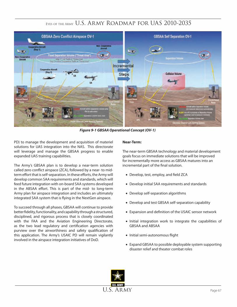
Eyes of the Army U.S. Army Roadmap for UAS 2010-2035
U.S. Army Page 67
Near-Term:
The near-term GBSAA technology and material development goals focus on immediate solutions that will be improved for incrementally more access as GBSAA matures into an incremental part of the final solution.
• Develop, test, employ, and field ZCA
• Develop initial SAA requirements and standards
• Develop self-separation algorithms
• Develop and test GBSAA self-separation capability
• Expansion and definition of the USAIC sensor network
• Initial integration work to integrate the capabilities of GBSAA and ABSAA
• Initial semi-autonomous flight
• Expand GBSAA to possible deployable system supporting disaster relief and theater combat roles
PD) to manage the development and acquisition of materiel solutions for UAS integration into the NAS. This directorate will leverage and manage the GBSAA progress to enable expanded UAS training capabilities.
The Army’s GBSAA plan is to develop a near-term solution called zero conflict airspace (ZCA), followed by a near- to mid-term effort that is self-separation. In these efforts, the Army will develop common SAA requirements and standards, which will feed future integration with on-board SAA systems developed in the ABSAA effort. This is part of the mid- to long-term Army plan for airspace integration and includes an ultimately integrated SAA system that is flying in the NextGen airspace.
To succeed through all phases, GBSAA will continue to provide better fidelity, functionality, and capability through a structured, disciplined, and rigorous process that is closely coordinated with the FAA and the Aviation Engineering Directorate, as the two lead regulatory and certification agencies with purview over the airworthiness and safety qualification of this application. The Army’s USAIC PD will remain vigilantly involved in the airspace integration initiatives of DoD.
Figure 9-1 GBSAA Operational Concept (OV-1)
Eyes of the Army U.S. Army Roadmap for UAS 2010-2035
U.S. ArmyPage 68
solution is subject to increases in travel time and costs. The active duty component is evaluating UAS bed down locations for airspace and facility feasibility to keep home station training intact. Training facilities must be in place to minimize the logistical and peripheral support burden on commanders while enhancing safe operations. Units must possess the ability to collectively train with UAS assets. Continuation training must support proficiency and currency requirements for returning UAS units. This training includes basic operator tasks, launch and recovery, laser and gunnery qualification, air-ground integration, MUM, and combined arms events. Based on UAS airspace and facility limitations, the use of regional sites and increased simulation are potential short-term solutions until wider UAS access to the NAS is possible.
The Army must be prepared to manage UAS proliferation and MUM integration in national, international, and combat airspace to maximize flexibility in the area of operations and minimize potential mishaps. Procedural deconfliction may be a necessity to allow for the sheer number of smaller UAS operating at lower altitudes, but we must develop smaller, lightweight deconfliction technologies. An automated air tasking order/air coordination order process in combat airspace, allow larger UAS to operate at higher altitudes where conflicts with manned aircraft are resolved. The development of responsive, agile integration procedures permits UAS to enhance mission performance. Joint information collection and dissemination procedures and standards enable flexible command and control for both preplanned and time sensitive missions. New technologies such as improved sensors and software-programmable radios must assist in addressing the challenges faced during combat and peacetime situations. Advanced navigation systems, publication of accurate airfield charts, development of collision avoidance systems, and implementation of common transit alert handling procedures provide robust solutions to satisfy FAA and international airspace requirements for most classes of airspace and most airfields.
Appendix E has a more detailed discussion of UAS airspace integration.
Mid-Term:
The mid-term GBSAA effort will enhance and improve the system as technologies mature and synergies from other airspace integration efforts occur.
• Improve ZCA
• Improve self-separation algorithms
• Expansion and definition of the USAIC sensor network
• Integration of GBSAA and ABSAA
• Initial autonomous flight
• Initial work to integrate GBSAA into NextGen airspace
Far-Term:
The far-term GBSAA effort will see a standard system that seamlessly provides local NAS access to all UAS and integrates with ABSAA to provide unfettered NAS access.
• Improve and upgrade all GBSAA systems as required
• Support, sustain, and maintain GBSAA
• Routine and unfettered “file and fly” access to the NAS for Army UAS using GBSAA integrated with ABSAA into NextGen
Fundamentally, there is a requirement of GBSAA to safely integrate into a terminal area or airspace facility to enable DoD UAS access to the NAS accommodating significantly increased cooperative and uncooperative traffic.
An airspace and facility cross analysis is needed to address facility requirements. There is not a “one-size fits all” solution suitable or appropriate for all installations. Each installation has unique geographical and airspace limitation challenges requiring individual, independent solutions for optimum UAS training. This analysis and recommendation must take top priority in order to incorporate resourcing requirements and resultant military construction.
Although home station training is the most desired, the Army National Guard and Army Reserve are presently evaluating locations as regional training sites for NET and possible regional sites for continuation training based on the severe shortage of facilities and airspace. This
Eyes of the Army U.S. Army Roadmap for UAS 2010-2035
U.S. Army Page 69
among the various echelons while using available spectrum more efficiently.
Electromagnetic spectrum is scarce and valuable. Most of the radio EMS is already allocated to users who may or may not be using it at a given time and place. The Army should explore technology expansion in the available spectrum by taking advantage of assigned unused spectrum at any particular point in time. This capability must prevent jamming and not interfere with other users.
Additionally, the Army must develop autonomous network communications for the cluttered urban environment. Urban clutter creates multiple problems resulting in weak and fading voice or data communications. To better transmit UAS data in urban environments, the Army must exploit phenomena such as multipath routing schemes and multipath routing in wireless networks to improve communications between vehicles moving in cities without using a fixed communications infrastructure. The Army also must continue its work in bridging strategic and tactical operations with high-speed, high-capacity communications networks.
The DoD has a continuing requirement for a high-speed network whose data rate is hundreds to thousands of megabits per second. To reach the battlefield-deployed elements, the network must reliably transmit data to the various elements and echelons worldwide. In response to this challenge, the DoD must develop a robust network management system that combines the high data-rate capability of laser communications with the high reliability of radio frequency communications to obtain the benefits of both.
The Army protects UAS communications from jamming, spoofing, unauthorized access and electromagnetic pulse (EMP). High-power jamming signals emit detectable signals that the Army quickly targets for destruction. Low power jamming is limited in range and frequency, making jamming reasonably ineffective. Network access limitations, encryption, and message acknowledgement protocols limit opportunity and effectiveness of enemy spoofing and unauthorized access efforts. However, defense against EMP requires significant effort because an EMP destroys unprotected electronic circuits. UAS communications and computerized control equipment rely upon electronic circuits to deliver their function. Protection of these circuits requires solutions such as shielding and redundancy. These solutions usually have space, weight, and power implications that are significant costs for UAS design. The Army must assess this threat and demand EMP protection commensurate with the assessment.
9.2 Electromagnetic Spectrum and Bandwidth Management
As unmanned systems (ground, sea, subsurface, and air) proliferate on the battlefield, electromagnetic spectrum (EMS) management becomes extremely critical. The C-band frequencies in particular prove to be problematic in expeditionary environments. For example, to counter the explosive hazard threat in OIF, radio frequency (RF) jammers that operate in the C-band often interfere with FMV and UAS operations. The OSD developed spectrum policy guidance, which all unmanned systems must adhere to, before the Military Communications Electronics Board certifies any system for production. Once fielded and deployed for operations, systems are subject to the theater spectrum manager’s directions. The electromagnetic spectrum manager coordinates all U.S. and host nation spectrum resource requests necessary in all operational environments. This ensures that unmanned systems do not interfere with critical host nation infrastructure that is reliant on unobstructed frequency bandwidth. This is crucial, as UAS will operate in very crowded frequency and bandwidth spectrums. Having a single central coordinating entity manage this problem will help to minimize interference. The bandwidth shortage limits the use of the number of unmanned systems in a geographical area. Whenever technically feasible, UAS should have the ability to employ alternate frequencies in order to best utilize the available portions of the spectrum.
9.3 Protected Communications
In general, there are three main areas of concern when considering link security: inadvertent or hostile interference of the uplink, similar interference of the downlink, and quality of service. The forward (“up”) link controls the activities and payload hardware of the platform itself. The command and control link requires a sufficient degree of security to ensure that only authorized agents have access to the control mechanisms of the platform. The return (“down”) link transmits critical performance and collects data from the platform payload to the Warfighter or analyst on the ground or in the air. Effective EMS allocation and management are essential to reducing inadvertent interference of the data links and ensuring the quality of service.
Not only must the data links supporting UAS operations be secure, but the Army must invest in developing technologies for wireless tactical net-centric warfare that will enable reliable, mobile, secure, self-forming, ad hoc networking
Eyes of the Army U.S. Army Roadmap for UAS 2010-2035
U.S. ArmyPage 70
9.5 Technological Balance between Manned and Unmanned Aircraft Systems
The proliferation of unmanned systems on the battlefield presents significant operational advantages as well as significant cultural implications. As an example, an Army aerial common sensor (ACS) wide area SIGINT and SAR/GMTI platform detects enemy forces, and vectors UAS using the ACS real-time sensor data. The lower flying UAS identifies the enemy forces as artillery, tank, and ADA assets. The UAS laser designates for a strike aircraft armed with laser-guided munitions to destroy the enemy forces. This process is very dependent on reliable communication and coordination among the ACS, UAS, and strike aircraft. MUM involves UGVs or unmanned surface vehicles as well. The Army demonstrated the utility of this concept in OIF with the now unclassified Task Force Observe, Detect, Identify, and Neutralize (ODIN) to defeat insurgents placing explosive hazards along major supply routes.
The technological implications on the military structure, particularly as unmanned systems become increasingly autonomous will be significant. Safety, diversity of risk between manned and unmanned systems, and separation of controllers from battlefield conditions are important considerations that need addressing.
Over the next 25 years, the Army aviation force mix shifts from being almost entirely manned to consisting of mostly unmanned and OPV. The following assessment of how the Army makes this shift is based upon the FY 2015 Aviation Force Structure modified table of organization and equipment (MTOE) dated 11 Sep 2008 as published in the 2009 Aviation Force Structure book. This analysis only considers rotorcraft in the force mix. The force mix is discussed in more detail in the near, mid, and far-term sections of this Roadmap.
9.4 Processing, Exploitation, and Dissemination of Information
The Army’s ability to collect information far outpaces its ability to use the information collected. Proliferation of UAS and other sensors highlights the need for advanced PED capabilities. Every sensor system must fit into a PED architecture that ensures pertinent intelligence reaches the appropriate organization for action via the battle command system. On-board processing, such as aided target recognition, is useful for choosing selected imagery (FMV or still) for analysis, because it reduces bandwidth requirements and focuses analyst workloads. Battle command systems must incorporate automated fusion engines to receive and integrate data and imagery cleared by analysts. Once information is fused, it requires addition to situational awareness suites for display. Automated subscription services must then ensure proper distribution to all interested personnel for action. Net-centric operations will make distribution easier, faster, and wider scope. The Army must ensure that future UAS and their products are interoperable with the Army Battle Command System (ABCS) architecture and enable users to rapidly and efficiently exchange relevant information from multiple sensors and applications. Unmanned systems collect a vast amount of data. A regularly updated data disposition policy ensures necessary data passes through limited bandwidth availability. Increased data compression and on-board processing will further reduce bandwidth requirements. Reduced size of transmitted data provides linear relief to burdened communications systems. Improved processing of images and other data serves to cull meaningless and unnecessary data before transmission thereby providing bandwidth relief to communications systems.
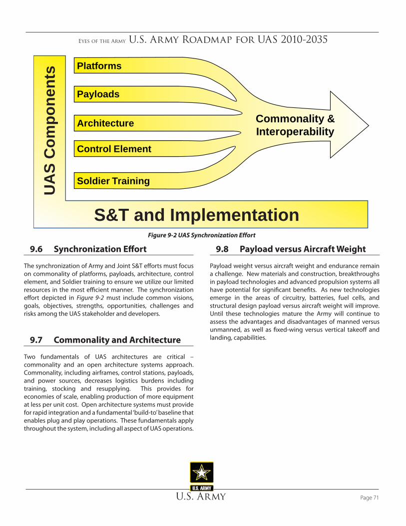
Eyes of the Army U.S. Army Roadmap for UAS 2010-2035
U.S. Army Page 71
9.8 Payload versus Aircraft Weight
Payload weight versus aircraft weight and endurance remain a challenge. New materials and construction, breakthroughs in payload technologies and advanced propulsion systems all have potential for significant benefits. As new technologies emerge in the areas of circuitry, batteries, fuel cells, and structural design payload versus aircraft weight will improve. Until these technologies mature the Army will continue to assess the advantages and disadvantages of manned versus unmanned, as well as fixed-wing versus vertical takeoff and landing, capabilities.
9.6 Synchronization Effort
The synchronization of Army and Joint S&T efforts must focus on commonality of platforms, payloads, architecture, control element, and Soldier training to ensure we utilize our limited resources in the most efficient manner. The synchronization effort depicted in Figure 9-2 must include common visions, goals, objectives, strengths, opportunities, challenges and risks among the UAS stakeholder and developers.
9.7 Commonality and Architecture
Two fundamentals of UAS architectures are critical – commonality and an open architecture systems approach. Commonality, including airframes, control stations, payloads, and power sources, decreases logistics burdens including training, stocking and resupplying. This provides for economies of scale, enabling production of more equipment at less per unit cost. Open architecture systems must provide for rapid integration and a fundamental ‘build-to’ baseline that enables plug and play operations. These fundamentals apply throughout the system, including all aspect of UAS operations.
Commonality &Interoperability
Platforms
Architecture
Payloads
Control Element
Soldier Training
S&T and Implementation
UA
S C
ompo
nent
s
Figure 9-2 UAS Synchronization Effort

Eyes of the Army U.S. Army Roadmap for UAS 2010-2035
U.S. ArmyPage 72
The sustainment/cargo UAS role significantly matures and supports approximately 25% of the aerial logistical resupply requirements Army wide. Utility and MEDEVAC UAS predominately remain in developmental stages throughout the mid-term. The Army becomes more net-centric, integrates OPV technology into all rotor wing aircraft and UAS exhibit increasing autonomy. The required number of pilots decreases as the number of UAS operators increases. Operators manipulate multiple platforms from a universal control system located on aircraft as well as ground vehicles.
• In the far-term, UAS conduct nearly all of the surveillance and C3 roles. UAS predominately conduct armed reconnaissance, attack, and sustainment/cargo missions while manned platforms support approximately 75% of the mission load. The majority of utility and MEDEVAC roles remain manned but start to transition to unmanned capabilities late in the far-term. UAS operate in all weather conditions, possess SAA capability, and fully integrate into the NAS. Sustainment/cargo UAS, MEDEVAC UAS, and Nano-technology with swarming capability emerge. Multi-purpose and multi-role UAS support the full range of military operations where operators control swarms of UAS from a common control system.
The UAS maturation rate is enabling combat commanders to employ a variety of UAS across the depth and breadth of the battlefield. Throughout the next 25-years, the Army will further transform based upon operational needs, lessons learned, and emerging technologies. The Army’s UAS Roadmap provides a comprehensive overview of current UAS capabilities through future employment potential. Support to current operations in both Iraq and Afghanistan is paramount while the Army maintains its focus on future, dissimilar battlefields and diverse areas of operation. UAS are a proven combat multiplier because they increase situational awareness, reduce workloads, and minimize the risk to the forward deployed Soldier. The Army must continue to leverage existing and emerging technologies to capitalize from UAS potential. The Roadmap is the Army’s first synchronized effort to outline UAS strategies for the next quarter-century by focusing on unmanned aircraft, emerging technologies, system interoperability, commonality, and most importantly continued support to the Warfighter. Our intent for the near, mid, and far-term is to describe capabilities we would like to have today and estimate how and when technological advances might bring that capability to bear. The fielding of technologically advanced unmanned systems is expected to deliver savings in force structure and costs over time. Only time will tell how accurate our first attempt is of foretelling the future capabilities expressed in this Roadmap.
10. Conclusion This Roadmap provides an aggressive but realistic vision of how the Army can exploit a proven combat multiplier. It outlines how the Army envisions UAS development and employment for the next 25 years. The Army will update the Roadmap to reflect our progress and improved understanding every two years, but its long-term value is the synchronization it achieves among diverse stakeholders. The Army intends to capitalize on UAS capabilities to improve Warfighter effectiveness with less risk. Over the next 25 years, UAS development and employment require investment in research and development, personnel, training and stationing facilities, materiel, and improved logistics. This Roadmap provides the structure for development and tracking of funding requirements over time.
The Army envisioned 25-years from now employs UAS across the operational environment, across functional areas and across the spectrum of operations as a key force multiplier. Principally, UAS extend Army capabilities in command and control, lethality, and transport. As the Army fields its advanced communications network, employs battle command systems that PED information, and modernizes its combat formations, UAS capabilities will manifest. Introduction and proliferation of UAS and other robotic systems represent significant changes to Army culture. Through documents like this Roadmap, Army leadership can prepare Soldiers for these changes.
The Army currently employs UAS across all echelons as dedicated or organic support to tactical maneuver and intelligence operations. In the future, the number of UAS organized in the Army will first quadruple and then double again as needs and capabilities increase. Throughout the next 25-years, the Army will further transform based upon lessons learned, operational needs, and emerging technologies, and UAS will continue to take on increasingly diverse roles to support the Soldier, but the full spectrum missions will not subside.
• In the near-term, the majority of surveillance is already conducted by unmanned platforms and will continue to increase in the mid and far-terms. UAS are ideally suited for armed reconnaissance and the capability remains in its infancy through the end of the near-term. Systems in the near-term include the ERMP, Hunter, Shadow, and Raven UAS and the S&T effort in the near-term focuses primarily on product improvement.
• In the mid-term, UAS will conduct the large majority of the surveillance and C3 missions and approximately half of the attack and armed reconnaissance missions.
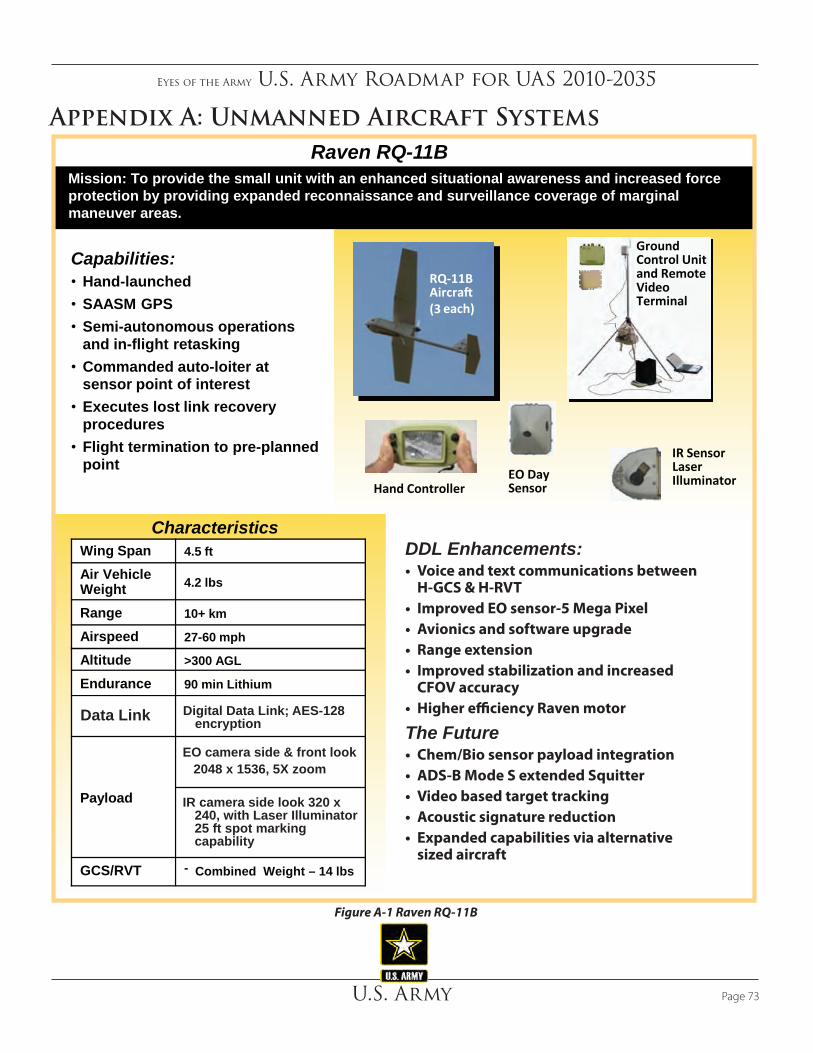
Eyes of the Army U.S. Army Roadmap for UAS 2010-2035
U.S. Army Page 73
Appendix A: Unmanned Aircraft Systems
Figure A‑1 Raven RQ‑11B
Mission: To provide the small unit with an enhanced situational awareness and increased force protection by providing expanded reconnaissance and surveillance coverage of marginal maneuver areas.
Capabilities:• Hand-launched• SAASM GPS• Semi-autonomous operations
and in-flight retasking• Commanded auto-loiter at
sensor point of interest• Executes lost link recovery
procedures• Flight termination to pre-planned
point
DDL Enhancements:• Voice and text communications between
H-GCS & H-RVT• Improved EO sensor-5 Mega Pixel• Avionics and software upgrade• Range extension• Improved stabilization and increased
CFOV accuracy• Higher efficiency Raven motor
The Future• Chem/Bio sensor payload integration• ADS-B Mode S extended Squitter• Video based target tracking• Acoustic signature reduction• Expanded capabilities via alternative
sized aircraft
Wing Span 4.5 ft
Air Vehicle Weight 4.2 lbs
Range 10+ km
Airspeed 27-60 mph
Altitude >300 AGL
Endurance 90 min Lithium
Payload
GCS/RVT - Combined Weight – 14 lbs
Characteristics
RQ-11B Aircraft (3 each)
Ground Control Unit and Remote Video Terminal
Hand ControllerEO Day Sensor
IR SensorLaser Illuminator
Raven RQ-11B
IR camera side look 320 x 240, with Laser Illuminator 25 ft spot marking capability
EO camera side & front look 2048 x 1536, 5X zoom
Digital Data Link; AES-128 encryptionData Link

Eyes of the Army U.S. Army Roadmap for UAS 2010-2035
U.S. ArmyPage 74
Figure A‑2 SUAS PIP System Description
The SUAS PIP enhances the Raven �ight capabilities, payload growth, and mission �exibility. Not a one size �ts all. Modular system components for speci�c size UA for speci�c capabilities required.
SUAS PIP System Description
Capabilities:• Laser illuminator and laser
designator for air/ground MUM teaming
• Modular components to customize UA for the mission
• H-GCS/H-RVT have OSRVT capabilities and features
• Voice communications between H-GCS and H-RVT via DDL
• Interoperable with UGV and UGS; small uniit “tool kit”
• Enhanced DTED targeting tool for improved TLE accuracy
• Digital Data Link (DDL) offers connectivity to FCS architecture
Increment 2• DDL allows for at least 32 UA/UGV/UGS
in the same area
• Laser designation capability
• Interoperability with UGV and UGS• H-GCS/H-RVT integrated with
RSTA laptop
• CBRN payloads• Increased operational range and
endurance 15km• Small unit communications relay• Hi fidelity embedded event and scenario
driven mission simulation
Main System Components:• Modular components for 3 different mission specific
UA con�gurations• ~12lb UA improved capabilities at the cost of a larger
footprint offering greater endurance (4 hrs), 360 degree PTZ payload capability, LD/LRF
• ~4lb UA similar to Raven B with improved optics, PTZ payload with LD/LRF, target auto-tracking capabilities while maintaining current Raven B footprint
• ~1lb UA for true micro capabilities with EO and IR capability, minimal system footprint
• H-GCS/H-RVT (hand controller and RSTA laptop all in one with OSRVT like capabilities).
• Field repair kit for each UA
Major Increment Upgrades:

Eyes of the Army U.S. Army Roadmap for UAS 2010-2035
U.S. Army Page 75
AV Weight 18 lbs System Weight 51 lbs
Range 10 km Endurance 47 minutes
Payload EO/IR/LD/LRF Sensor
Max Speed 45 mph
Flight Characteristics
Hover and Stare Capable
Mission: Provide dedicated mission- con�gured, UAV to meet the small unit needs for a Reconnaissance and Surveillance (R&S) System with hover, persistent stare, and vertical launch/land capabilities
gMAV Small Unmanned Aircraft System (SUAS)
Capabilities:• Platoon/Company level asset
• Single soldier portable• Operates in urban and
complex terrain
• Manual or automated flight
• EO/IR payloads
The Future:• DDL Integration/Test Ongoing• Design Review DEC 09• Production Readiness Review JUN 10• First Prototype AUG 10• Production AUG - DEC 10• Fielding SEP 10 - MAR 11
Characteristics:
Figure A‑3 gMAV SUAS
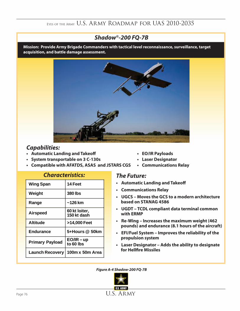
Eyes of the Army U.S. Army Roadmap for UAS 2010-2035
U.S. ArmyPage 76
Figure A‑4 Shadow‑200 FQ‑7B
Mission: Provide Army Brigade Commanders with tactical level reconnaissance, surveillance, target acquisition, and battle damage assessment.
Shadow®-200 FQ-7B
Capabilities:• Automatic Landing and Takeoff• System transportable on 3 C-130s• Compatible with AFATDS, ASAS and JSTARS CGS
• EO/IR Payloads• Laser Designator• Communications Relay
The Future:• Automatic Landing and Takeoff• Communications Relay• UGCS – Moves the GCS to a modern architecture
based on STANAG 4586• UGDT – TCDL compliant data terminal common
with ERMP• Re-Wing – Increases the maximum weight (462
pounds) and endurance (8.1 hours of the aircraft)• EFI/Fuel System – Improves the reliability of the
propulsion system• Laser Designator – Adds the ability to designate
for Hellfire Missiles
Characteristics:Wing Span 14 Feet
Weight 380 lbs
Range ~126 km
Airspeed 60 kt loiter, 150 kt dash
Altitude >14,000 Feet
Endurance 5+Hours @ 50km
Primary Payload EO/IR – up to 60 lbs
Launch Recovery 100m x 50m Area

Eyes of the Army U.S. Army Roadmap for UAS 2010-2035
U.S. Army Page 77
Figure A‑5 Hunter MQ‑5B
Mission: Provide Division/Corps Level reconnaissance, surveillance, target acquisition, and battle damage assessment.
Hunter MQ-5B Tactical Concepts
Capabilities:• Corps, Division and Brigade Users• Versatile Payload Platform• Multi Mission Configurations
• Extended Range/Endurance UAV• Attack Capable (Viper Strike)• Voice Over Transmission (VOX) Capability
The Future:• Tri/Quad Sensor Payload• Automatic Takeoff and Landing System• Tactical Common Data Link• OSRVT• GPS Viper Strike• Hunter Rewing
Characteristics:Wing Span 34.25 Ft
Weight 1,950 Lbs
Range ~200Km
Airspeed 62 Kts Loiter (110 Kts Dash)
Altitude >18,000 Ft
Endurance 25 Hours EO/IRPrimary Payload – Max Wt 275 Lbs 770 EO/IR –80 Lbs
Launch/Recovery Unimproved Runway – 1600 Ft

Eyes of the Army U.S. Army Roadmap for UAS 2010-2035
U.S. ArmyPage 78
Mission: Unmanned aircraft system capable of sustained 24 hour a day operations. Modular system provides commanders armed RSTA and battle damage assessment with full motion video of named areas of interest with EO/IR sensor and laser designation/marking. Command, Control and Data receipt via C-Band/SATCOM data link.
Warrior-A, Block 0
Capabilities:• Sustained 24 hour a day operations• Modular system• Capable of providing near real time video w/EO/IR
sensor and laser designation• Change detection using Synthetic Aperture Radar
• Extended Range/Endurance UAV• Blue Force Tracker• Attack Capable • Secure Comms/Retrans• Heavy Fuel Engine (Block 0)
The Future:• Continued Integration of Blue Force Tracker
• Weaponization Integration (Warrior A)
• Beyond LOS Secure Comms w/ARC 231
• CRP Integration
• Interoperability Certi�cation
Characteristics:Wing Span 55/56 ft (A/0)
Max GTOW 2550/3600 lbs (A/0)
Range with Relay
125 km LOS / 1200 km SATCOM
Max Airspeed 120/130 kts (A/0)
Altitude 25000/29000 ft (A/0)
Endurance 22/18 hours (A/0)
Weapon Up to 2/4 Hellfire Missiles (A/0)
Launch/ Recovery
3000/3200 ft @ 9k ft DA (A/0)
Figure A‑6 Deployed Preproduction ER/MP Assets
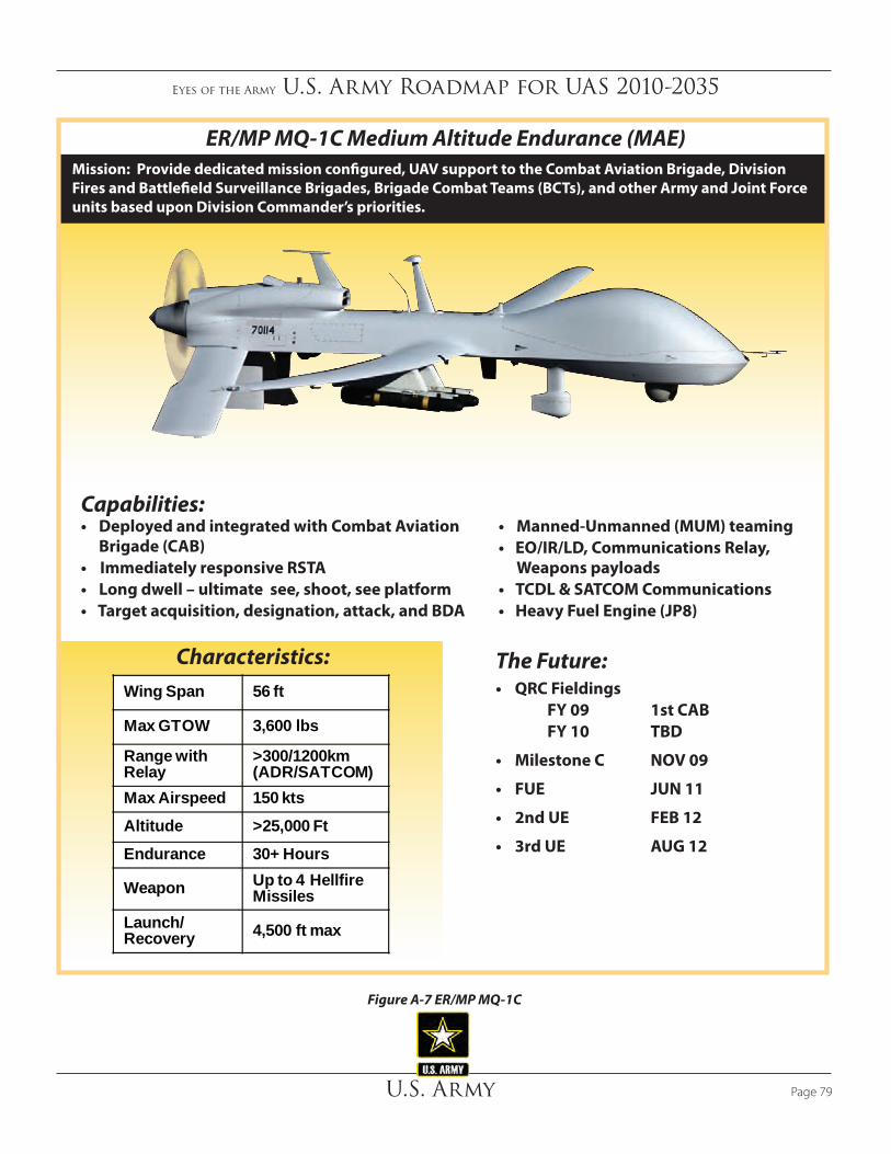
Wing Span 56 ft
Max GTOW 3,600 lbs
Range with Relay
>300/1200km (ADR/SATCOM)
Max Airspeed 150 kts
Altitude >25,000 Ft
Endurance 30+ Hours
Weapon Up to 4 Hellfire Missiles
Launch/ Recovery 4,500 ft max
Mission: Provide dedicated mission con�gured, UAV support to the Combat Aviation Brigade, Division Fires and Battle�eld Surveillance Brigades, Brigade Combat Teams (BCTs), and other Army and Joint Force units based upon Division Commander’s priorities.
ER/MP MQ-1C Medium Altitude Endurance (MAE)
Capabilities:• Deployed and integrated with Combat Aviation
Brigade (CAB)• Immediately responsive RSTA• Long dwell – ultimate see, shoot, see platform• Target acquisition, designation, attack, and BDA
• Manned-Unmanned (MUM) teaming• EO/IR/LD, Communications Relay,
Weapons payloads• TCDL & SATCOM Communications• Heavy Fuel Engine (JP8)
The Future:• QRC Fieldings FY 09 1st CAB FY 10 TBD
• Milestone C NOV 09
• FUE JUN 11
• 2nd UE FEB 12
• 3rd UE AUG 12
Characteristics:
Eyes of the Army U.S. Army Roadmap for UAS 2010-2035
U.S. Army Page 79
Figure A‑7 ER/MP MQ‑1C

Eyes of the Army U.S. Army Roadmap for UAS 2010-2035
U.S. ArmyPage 80
Figure A‑8 XM156 Class 1
XM156 Class I UAS
Capabilities• DedicatedUAScapabilityatthelowestechelon
• Hover&StareCapabilityenablingobservationofurbaninfrastructure
• ElectroOptical,Infrared,LaserDesignation,LaserRangeFinder(EO/IR/LD/LRF)Sensor
• 10hpHeavyFuelEngine(HFE)
Mission:Providesaday/nightreconnaissanceandsecurity/earlywarningcapabilityfortheFCSBCTattheplatoon/companyechelondedicatedassettoconductReconnaissance,Surveillance,andTargetAcquisition(RSTA)/Designation.

Eyes of the Army U.S. Army Roadmap for UAS 2010-2035
U.S. Army Page 81
Figure A‑9 OSRVT Common Systems Integration
Block 1 Key Capabilities• Multi-Platformintegration• Highqualityvideodisplayforrecognition/identification• DVR,TIVOlikecapability-10hoursofrecordingvideo• TelemetryDatalinkedtoFalconVieww/2525Symbology
The Future• IntegratedintoA2C2S,Stryker,andApache
–WorkingIntegrationinto MRAP, OH58,UH60,ACS,RG31Mk5e,CPOTM
• ApacheVUIT-2likeintegrationonotherplatforms(OH-58/UH-60)
• eRoverIIIOSRVT-SBandCapabilityretrofitFUE4thQtrFY09
• OSRVTIncrement2CPD-atArmy3StarStaffing• AESEncryption-FUE4thQtrFY09• ROVER6OSRVT(TypeIEncryption)-FUE2ndQtrFY10
• DDL-FUE1stQtrFY10
Description:OSRVTisanintegratedkitthatprovidesenhancedsituationalawarenesswithnearRealTimeVideoandTelemetryDatafrommultiplemannedandunmannedplatforms:Raven,Shadow,Hunter,ER/MP,Predator,andUASandmannedLiteningPodplatforms.
TheOSRVTkitconsistsofUHFModem,cables,softwareandanoptionalextendedrangeantenna.SoftwaresupportsdecodingTelemetryandMETADatafrommultipleUAS,linksdataontoFalconViewmaps,andsupportsOffTargetCalculations.
OSRVTFielding:2,395oncontract-1,363shippedtodate.
One System Remote Video Terminal (OSRVT)
• JPEGFileswithEmbeddedMetadata• OffTargetCalculations• Tri-Band(C/L/Ku)ExtendedRangeAntenna,upto50km
• IntegrationintoA2C2S,Stryker,Apache,DCGS-A,TACTICOMP,etc.
Cables and Software
C/L Band10km
KU Band
Receiver
Toughbook
UHF Modem
OptionalE-ROVER III Components
Mobile Directional Antenna System, (MDAS), <50km

Eyes of the Army U.S. Army Roadmap for UAS 2010-2035
U.S. ArmyPage 82
Page Left Intentionally Blank

Eyes of the Army U.S. Army Roadmap for UAS 2010-2035
U.S. Army Page 83
and the complex information processing capability of modern digital electronics to provide high-resolution imagery. Synthetic aperture radar complements pho-tographic and other optical imaging capabilities be-cause of the minimum constraints on time-of-day and atmospheric conditions and because of the unique responses of terrain and cultural targets to radar frequencies. Synthetic aperture radar technology has provided terrain structural information to geologists for mineral exploration, oil spill boundaries on water to environmentalists, sea state and ice hazard maps to navigators, and reconnaissance and targeting infor-mation to military operations.
• Moving Target Indicator (MTI). An MTI is a radar presentation that shows only targets that are in motion. Signals from stationary targets are subtract-ed out of the return signal by the output of a suitable memory circuit.
• Light Detection And Ranging (LIDAR). The LIDAR payloads have the potential to provide a wide range of capabilities. In addition to the capabilities in the preceding paragraph, LIDAR may be used for explosive hazards detection and weather predicting (e.g., Doppler LIDAR could provide data such as cloud density, wind speed, and real-time vertical wind pro-files). Also, a multispectral LIDAR payload designed to detect and image effluents that are associated with chemical and biological warfare agents.)
• Laser Radar (LADAR). The LADAR performs three dimensional imaging. It has the capability to look through cover such as trees, foliage, and cam-ouflage. LADAR produces a virtual picture to reliably identify previously “hidden” targets (tanks, other ve-hicles, air defense systems, etc.). This technology also has the potential for assisting with explosive hazard detection.
• Chemical, Biological, Radiological, Nuclear, high yield Explosives Detection (CBRNE). Research and development in smaller, lighter, and more sensitive CBRNE sensor packages will increase the capability of UAS. Compact, active multispectral chemical sensors will enable the remote detection of chemicals associated with weapons.
Appendix B: Unmanned Aircraft Systems Payloads
Unmanned aircraft system payloads improve Warfighters situational awareness in areas such as ISR and RSTA; laser designation; damage assessment; CBRNE detection and monitoring; cargo delivery, logistics resupply and communications gateway extension (e.g., communications relay, network extension, cross banding/cross protocols). Law enforcement, fire fighters, and civil support personnel also benefit from UAS operation within the U.S. UAS may assist in non-kinetic psychological operations; combat identification; early warning; locating and monitoring enemy military equipment; monitoring borders for smuggling; detecting mines (land and sea); infrastructure reconstitution; geospatial intelligence and SIGINT support; maritime vessel identification; meteorological and oceanographic condition (METOC) monitoring support; personnel recovery; and support to law enforcement.
UAS payloads include sensors, communications relay, weapons, and cargo. Payloads may be internal or external to the UAS.
B.1 Sensors Payloads
Sensor payloads include optical, radar, laser rangefinder, laser designation, explosive hazards detection, CBRNE detection, and environmental measurements.
B.2 Sensor Types• Electro- optical (EO). This sensor is a camera
that operates in the visible range. Sensor imagery data include FMV, still frame imagery, image-intensi-fied imager, blended imagery, and fused imagery.
• Infrared (IR). This sensor is a camera that operates in the infrared spectrum. Sensor imagery data include FMV and still frame imagery.
• Synthetic Aperture Radar (SAR). The SAR provides near-all weather, high-resolution, broad-area imagery. SAR systems take advantage of the long-range propagation characteristics of radar signals

Eyes of the Army U.S. Army Roadmap for UAS 2010-2035
U.S. ArmyPage 84
– Some UAS have sensors capable of topographical mapping and object mensuration. Detailed information such as height, length, width, and position of objects (such as perimeter walls, buildings, trees, equipment, etc.) can be determined once the imagery has been correlated with other sources See Table B-1 for specific sensor payload characterisitics..
• Signal intelligence (SIGINT) sensors. The SIGINT sensor capabilities provide detection, identifi-cation, geolocation and copy of communications and non-communications emitters to provide situational awareness and intelligence on an adversary’s capa-bilities, disposition, composition and intentions. In turn, this intelligence is used for lethal and non-le-thal targeting. SIGINT also provides for force protec-tion and indications and warning. Due to security classifications, SIGINT data will typically be processed at a secure facility physically separated from the GCS and UAS unit operating the aircraft employing the SIGINT sensor.
• Measurement and Signatures Intelligence (MASINT) sensors. The MASINT sensors exploit fundamental properties and/or characteristics of objects of interest that are limited or unavailable with traditional intelligence collection systems and domains such as GEOINT, IMINT, SIGINT and HUMINT. For example, a MASINT sensor on a UAS could per-form a spectrum analysis role to detect signature data associated with the explosive components of IEDs and drug lab chemicals. The MASINT sensors could include an active capability to stimulate signatures from some targets. MASINT techniques also include the collection of the raw properties of objects with advanced radar, electro-optical, infrared, spectral, magnetic, nuclear, olfactory, acoustic, and seismic sensors. Advances in data collection, processing, and storage hardware and software are laying the foun-dation for practical application of MASINT collection techniques from UAS.
• Laser range finder/designator. These pulse laser systems enable accurate and instantaneous distance and speed measurement for target location and the ability to provide target designation for laser guided weapons.
• Environmental sensors.
– METOC sensors are used to monitor weather conditions and may be inte-grated into several UA payload con-figurations. This data serves to provide local and forecasting data in support of such diverse missions as applying lethal fires to providing tropical storm tracking.
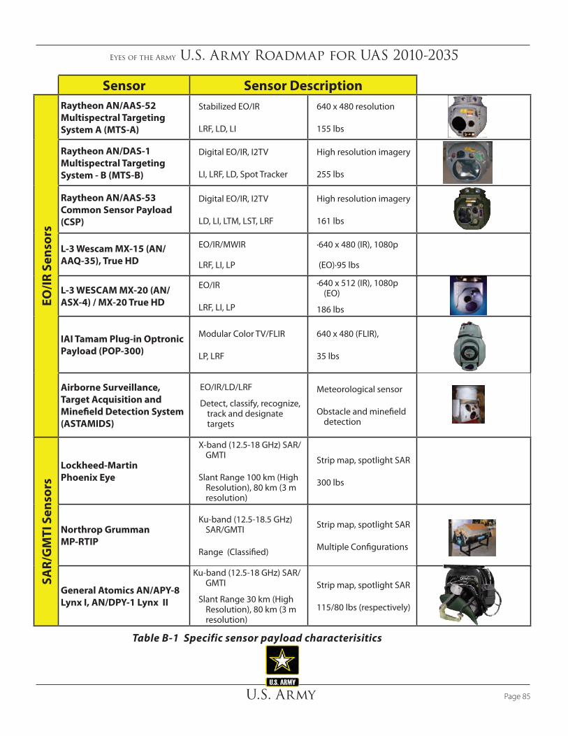
Eyes of the Army U.S. Army Roadmap for UAS 2010-2035
U.S. Army Page 85
Sensor Sensor Description
EO/IR
Sen
sors
Raytheon AN/AAS-52 Multispectral Targeting System A (MTS-A)
Stabilized EO/IR
LRF, LD, LI
640 x 480 resolution
155 lbs
Raytheon AN/DAS-1 Multispectral Targeting System - B (MTS-B)
Digital EO/IR, I2TV
LI, LRF, LD, Spot Tracker
High resolution imagery
255 lbs
Raytheon AN/AAS-53 Common Sensor Payload (CSP)
Digital EO/IR, I2TV
LD, LI, LTM, LST, LRF
High resolution imagery
161 lbs
L-3 Wescam MX-15 (AN/AAQ-35), True HD
EO/IR/MWIR
LRF, LI, LP
·640 x 480 (IR), 1080p
(EO)·95 lbs
L-3 WESCAM MX-20 (AN/ASX-4) / MX-20 True HD
EO/IR
LRF, LI, LP
·640 x 512 (IR), 1080p (EO)
186 lbs
IAI Tamam Plug-in Optronic Payload (POP-300)
Modular Color TV/FLIR
LP, LRF
640 x 480 (FLIR),
35 lbs
Airborne Surveillance, Target Acquisition and Minefield Detection System (ASTAMIDS)
EO/IR/LD/LRF
Detect, classify, recognize, track and designate targets
Meteorological sensor
Obstacle and minefield detection
SAR/
GM
TI S
enso
rs
Lockheed-Martin Phoenix Eye
X-band (12.5-18 GHz) SAR/GMTI
Slant Range 100 km (High Resolution), 80 km (3 m resolution)
Strip map, spotlight SAR
300 lbs
Northrop Grumman MP-RTIP
Ku-band (12.5-18.5 GHz) SAR/GMTI
Range (Classified)
Strip map, spotlight SAR
Multiple Configurations
General Atomics AN/APY-8 Lynx I, AN/DPY-1 Lynx II
Ku-band (12.5-18 GHz) SAR/GMTI
Slant Range 30 km (High Resolution), 80 km (3 m resolution)
Strip map, spotlight SAR
115/80 lbs (respectively)
Table B‑1 Specific sensor payload characterisitics
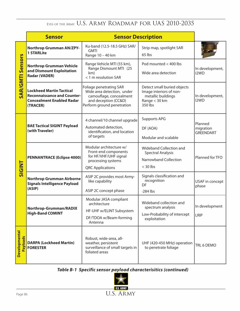
Eyes of the Army U.S. Army Roadmap for UAS 2010-2035
U.S. ArmyPage 86
Sensor Sensor Description
SAR/
GM
TI S
enso
rs
Northrop Grumman AN/ZPY-1 STARLite
Ku-band (12.5-18.5 GHz) SAR/GMTI
Range 10 – 40 km
Strip map, spotlight SAR
65 lbs
Northrop Grumman Vehicle and Dismount Exploitation Radar (VADER)
Range Vehicle MTI (55 km), Range Dismount MTI (25 km)
< 1 m resolution SAR
Pod mounted < 400 lbs
Wide area detectionIn development, I2WD
Lockheed Martin Tactical Reconnaissance and Counter-Concealment Enabled Radar (TRACER)
Foliage penetrating SARWide area detection, under
camouflage, concealment and deception (CC&D)
Perform ground penetration
Detect small buried objectsImage interiors of non-
metallic buildingsRange < 30 km350 lbs
In development, I2WD
SIG
INT
BAE Tactical SIGINT Payload (with Traveler)
4 channel/10 channel upgrade
Automated detection, identification, and location of targets
Supports APG
DF (AOA)
Modular and scalable
Planned migration GREENDART
PENNANTRACE (Eclipse 4000)
Modular architecture w/ Front-end components for HF/VHF/UHF signal processing systems
QRC Applications
Wideband Collection and Spectral Analysis
Narrowband Collection
< 30 lbs
Planned for TFO
Northrop Grumman Airborne Signals Intelligence Payload (ASIP)
ASIP 2C provides most Army-like capability
ASIP 2C concept phase
Signals classification and recognition
DF
·284 lbs
USAF in concept phase
Northrop-Grumman/RADIX High-Band COMINT
Modular JASA compliant architecture
HF-UHF w/ELINT Subsystem
DF/TDOA w/Beam-forming Antenna
Wideband collection and spectrum analysis
Low-Probability of intercept exploitation
In development
LRIP
Dev
elop
men
tal
Payl
oads
DARPA (Lockheed Martin) FORESTER
Robust, wide-area, all-weather, persistent surveillance of small targets in foliated areas
UHF (420-450 MHz) operation to penetrate foliage TRL 6 DEMO
Table B‑1 Specific sensor payload characterisitics (continued)

Eyes of the Army U.S. Army Roadmap for UAS 2010-2035
U.S. Army Page 87
Sensor Sensor Description
Dev
elop
men
tal P
aylo
ads
Northrop Grumman ASTAMIDS
Multi-sensor – FLIR, MSI, EO, Laser rangefinder, laser designator, laser illuminator
Lightweight and compact at ~79 lbs and < 15” diameter
CPD undergoing revision, currently in TRADOC staffing
Buckeye
High resolution color photogrammetric camera w/LIDAR (fused imagery product
3-10cm resolution
9000 AGL optimal altitude
32-39 mpx CameraUAS version in development
Hyper SAR (Cleanearth Technology
HSI/SAR
Fused spectral and SAR products
150lbs Pod Mounted
1.7 ft GSD
Cooperative work the Huachuca BL
TRL 6
Aurora Generation IV (BAE)
Design for RQ-7B platform
Wide-area surveillance 200sq mi
Automated Target detection
6 mpx Framing/ Video camera
DARPA program 5 built for PM UAS
ONS 07-1357 ; TRL 6
Pico-STAR (Selex-Galileo)
Burst illumination LADAR
FMV/IR imaging AESA Radar for detection
and geolocation TRL 6 Demo ready
HSI Naval Research
Laboratories MX-20SWHyperspectral SWIR Imager
·Area/Spot MASINT Exploitation
1280 x 720 high resolution
·Range 5 – 25 mi
In development, QRC Radiant Falcon
AEA
Pay
load
s
Northrop Grumman MADE (Multi-mission)
·Integrated Digital Rcvr/Exciter detects, identifies and generates advanced ECM
·4-7lbs + Antennas Comms/Radar Jammer TRL 6 DEMO ready
BAE IRON NAIL Airborne Counter-RCIED system
·GENIE payload adds RF IED Detect capability
47lbs, 200W Output
VHF to UHF
Operational on Pioneer Successful Demo w/Marines
DARPA CORPORAL
AIS SLEDGEHAMMER
DRT based technology Primary Platform RQ-7B
DRT Based Architecture
Primary Platform UH-60
25lbs + Antenna ERP up to 200W
<200 lbs
1500 ERP
HF to SHF
JCTD
Barrage Jammer
Raytheon MALD
POD mounted Airborne Electronic Attack
Low-band to high-band jamming capability
Advanced filtering techniques reduce risk of EM fratricide
TRL 7/8 on manned fighter aircraft, requires development for UAS employment
Comms EA w/Surveillance and Recon (CESAR)
Based on EA-18G payload
C-12 Platform
139lbs POD solution
VHF to UHF
1680 ERP
TRL 7
Table B‑1 Specific sensor payload characterisitics (continued)

Eyes of the Army U.S. Army Roadmap for UAS 2010-2035
U.S. ArmyPage 88
capabilities. The inclusion of SIGINT capabilities provides the Warfighter with a multi-intelligence UAS solution.
In the FY 2010-2015 period ERMP will begin fielding starting with QRC 1 and 2, followed by the FUE in FY2011. The ERMP QRC 1 and 2 platforms will carry the Raytheon AN/DAS-2 EO/IR/LD payload providing wide area search (WAS) and tracking of moving targets. The ERMP QRC 2 will include SAR/GMTI capabilities with the General Atomics LYNX II radar. The addition of the SAR/GMTI will enable Soldiers to employ multi-mission capability supporting threat detection, recognition, identification, and target acquisition. Further QRC 2 capabilities may include the addition of the Tactical SIGINT Payload (after initial deployment) supporting automated detection, identification, and direction finding capabilities.
The ERMP will commence fielding of the Increment I system in this period integrating the Raytheon AN/AAS-53 Common Sensor Payload (CSP), Northrop Grumman AN/ZPY-1 Small Tactical – Lightweight (STARLite) SAR/GMTI, and the Tactical SIGINT Payload capability. The culmination of these sensors provides the Warfighter with a scalable capability mix. The CSP provides long-range detection and recognition with low target location error. EO/IR with Image Intensification TV (I2TV) brings FMV capability in day/night conditions. Lasing capabilities include laser designation, laser spot tracking, laser target marker, and a laser rangefinder. The sensor supports WAS and auto tracking military sized targets. Finally, the CSP will transition to high-definition video in the FY2010-2015 period.
The STARLite SAR/GMTI sensor enables the ERMP to perform long-range early warning, detection, and tracking of vehicle sized moving targets at extended ranges and near-all weather SAR imaging capability. The GMTI will be able to detect and track vehicle-sized targets. SAR imaging can collect continuous images in a high-resolution spot or a strip mode, for either extended time duration or a given set of coordinates.
The combination of CSP and STARLite will provide the Army with increased SA, force protection indications and warnings, and improved target acquisition using a modular platform agnostic payload that detects, identifies, locates, copies, and provides precision guidance to ground-based forces. These near-term capabilities will directly support the BCT, need to find, fix, finish, exploit, analyze, and disseminate highly mobile, adaptive high value individuals or targets in high density, complex environments in minutes.
Increased efforts are required to develop, test, and field sensors to meet immediate Warfighter needs. Efforts on risk
B.2.1 Near‑term Capabilities (FY 2010 – 2015)
The Army will rapidly integrate sensors and payloads for UAS in the 2010-2015 timeframe, with heavy emphasis on the ERMP platform. The sensors and payloads in this period will meet the urgent capability needs outlined in the DoD FY 2009-2034 Unmanned Systems Integrated Roadmap. Sensor and payload improvements enhance reconnaissance and surveillance, target identification and designation, counter-mine and explosive ordnance disposal, and CBRNE. The intent is to field these enhancements quickly to meet the Soldier’s ever evolving battlefield requirements.
The RQ-7B Shadow TUAS system will continue to provide valuable situational awareness to the Warfighter with enhancements to the EO/IR payload. The current RQ-7B with the Tamam POP-300 Plug-in Optronic Payload (POP) provides the Warfighter with a modular, compact, lightweight electro-optical payload. The POP-300 provides day/night reconnaissance, surveillance, target acquisition, detection, and identification of targets. The resolution of the POP-300 is sufficient to recognize military-sized targets from operational altitudes offering continuous zoom for the EO camera and three selectable IR fields of view. The next RQ-7B upgrade includes the Tamam POP-300 in an EO/IR/laser designator (LD) configuration. This version of the POP provides the Soldier with a simultaneous configuration to support day/night FMV and laser pointer. This POP-300 variant provides increased detection ranges of 20 percent and incorporates a video enhancement device (VED) to support improved target identification. The combination of the new optics and VED can provide up to a 30 – 40 percent recognition range increase.
In addition to newer optics, the RQ-7B Shadow will have laser designation capabilities added to the sensor suite. Further system enhancements include the addition of the Video Verification of Identity (VIVID) multiple target tracking system. The VIVID capability is a complementary payload that enables tracking multiple targets simultaneously via processing the video received by the EO/IR payload onboard the Shadow. The acquisition of SAR/GMTI during this period will provide Soldiers with greater situation awareness and early warning in adverse weather/low-visibility conditions.
The MQ-5B Hunter will continue to be the workhorse for the AEB currently using the Tamam Multi-mission Optronic Stabilized Payload (MOSP) 770 EO/IR/LD supporting three fields of view in both the EO and IR modes. Growth for the Hunter includes the migration to the MOSP Quad sensor providing EO/IR/LD
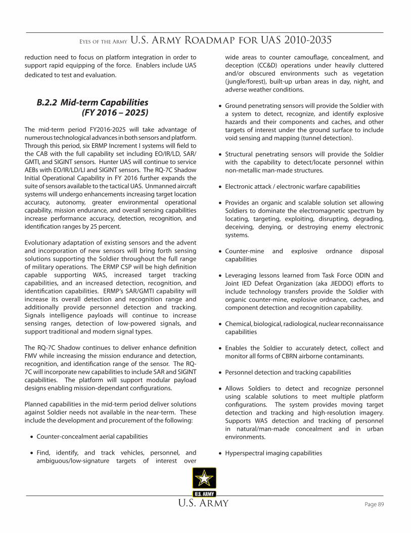
Eyes of the Army U.S. Army Roadmap for UAS 2010-2035
U.S. Army Page 89
reduction need to focus on platform integration in order to support rapid equipping of the force. Enablers include UAS dedicated to test and evaluation.
B.2.2 Mid‑term Capabilities (FY 2016 – 2025)
The mid-term period FY2016-2025 will take advantage of numerous technological advances in both sensors and platform. Through this period, six ERMP Increment I systems will field to the CAB with the full capability set including EO/IR/LD, SAR/GMTI, and SIGINT sensors. Hunter UAS will continue to service AEBs with EO/IR/LD/LI and SIGINT sensors. The RQ-7C Shadow Initial Operational Capability in FY 2016 further expands the suite of sensors available to the tactical UAS. Unmanned aircraft systems will undergo enhancements increasing target location accuracy, autonomy, greater environmental operational capability, mission endurance, and overall sensing capabilities increase performance accuracy, detection, recognition, and identification ranges by 25 percent.
Evolutionary adaptation of existing sensors and the advent and incorporation of new sensors will bring forth sensing solutions supporting the Soldier throughout the full range of military operations. The ERMP CSP will be high definition capable supporting WAS, increased target tracking capabilities, and an increased detection, recognition, and identification capabilities. ERMP’s SAR/GMTI capability will increase its overall detection and recognition range and additionally provide personnel detection and tracking. Signals intelligence payloads will continue to increase sensing ranges, detection of low-powered signals, and support traditional and modern signal types.
The RQ-7C Shadow continues to deliver enhance definition FMV while increasing the mission endurance and detection, recognition, and identification range of the sensor. The RQ-7C will incorporate new capabilities to include SAR and SIGINT capabilities. The platform will support modular payload designs enabling mission-dependant configurations.
Planned capabilities in the mid-term period deliver solutions against Soldier needs not available in the near-term. These include the development and procurement of the following:
• Counter-concealment aerial capabilities
• Find, identify, and track vehicles, personnel, and ambiguous/low-signature targets of interest over
wide areas to counter camouflage, concealment, and deception (CC&D) operations under heavily cluttered and/or obscured environments such as vegetation (jungle/forest), built-up urban areas in day, night, and adverse weather conditions.
• Ground penetrating sensors will provide the Soldier with a system to detect, recognize, and identify explosive hazards and their components and caches, and other targets of interest under the ground surface to include void sensing and mapping (tunnel detection).
• Structural penetrating sensors will provide the Soldier with the capability to detect/locate personnel within non-metallic man-made structures.
• Electronic attack / electronic warfare capabilities
• Provides an organic and scalable solution set allowing Soldiers to dominate the electromagnetic spectrum by locating, targeting, exploiting, disrupting, degrading, deceiving, denying, or destroying enemy electronic systems.
• Counter-mine and explosive ordnance disposal capabilities
• Leveraging lessons learned from Task Force ODIN and Joint IED Defeat Organization (aka JIEDDO) efforts to include technology transfers provide the Soldier with organic counter-mine, explosive ordnance, caches, and component detection and recognition capability.
• Chemical, biological, radiological, nuclear reconnaissance capabilities
• Enables the Soldier to accurately detect, collect and monitor all forms of CBRN airborne contaminants.
• Personnel detection and tracking capabilities
• Allows Soldiers to detect and recognize personnel using scalable solutions to meet multiple platform configurations. The system provides moving target detection and tracking and high-resolution imagery. Supports WAS detection and tracking of personnel in natural/man-made concealment and in urban environments.
• Hyperspectral imaging capabilities

Eyes of the Army U.S. Army Roadmap for UAS 2010-2035
U.S. ArmyPage 90
B.3 Future Sensing Advancements
• Future technological advancements should allow sensor payloads to be smaller, lighter and more energy efficient. Lighter, more compact and efficient UA electric power sources will permit the UA to carry more complex payloads. For example, additional UA power output may enable small UA to carry electronic jamming payloads.
• Future sensor developments will increase area coverage, revisit rate, improve classification and identification capabilities, develop non-traditional tracking techniques, and develop advanced CBRNE sensors. New capabilities such as environmental sensors, multispectral sensors, and hyper/ultra-spectral sensors expand the possibilities of UA sensor suites. Wide area sensors may replace narrow field of view sensors with the ability to cross cue to multiple points of interest for multiple users. Future sensors will provide the capability to track specific individuals, recognized through automatic target recognition capabilities, including if they are carrying weapons or other equipment. They also will be able to distinguish between males, females, and children, as well as different types of animals.
• Future UAS must address operating in CBRNE environments. For example, UAS subsystems will need to be survivable and able to continue operations following a high-altitude EMP event from a nuclear detonation.
• Modularity (common form factor, common interfaces) in payloads will improve the utility of UAS as multi-function platforms. Adoption of open system architecture protocols as industry and DoD standard will enable UA to carry multiple modular payloads (e.g., plug and play). Modularity links new technologies to the UAS quickly without modifying the platform itself.
• Improvements will continue in target location accuracy due to such sensors as a metric sensor. The metric sensor derives precision geo-coordinates (e.g., direct positioning) by accurately measuring both position and attitude data. Metric sensor will reduce costly critical downstream geospatial intelligence dependencies required to improve geo-positioning accuracy. It reduces timelines associated with coordinate generation to support coordinate seeking weapons for time critical strikes, and is a key enabler to achieve tactical persistence surveillance.
• Enables Soldiers to detect, classify, and identify targets against background phenomenology. May be fused with EO/IR or SAR imagery producing high-resolution multi-source imagery, enables coherent change detection, and signature identification.
• Light detection and ranging
• Provide Soldiers scalable LIDAR solutions supporting multiple classes of aircraft supporting high-fidelity terrain and geospatial reference data.
B.2.3 Far‑term Capabilities (FY 2026 – 2035)
Far-term (FY 2026–2035) sensor capabilities will require substantially greater flexibility, responsiveness, and onboard processing providing the Soldier with greater situational understanding. The UAS will be required to perform missions for days/weeks/months as compared to the current systems that measure mission time in hours. Furthermore, sensors must be able to collaborate and share data/information real-time between Army, Joint and Coalition unmanned aircraft. Sensing ranges should increase 50 percent as compared to current systems and support fully autonomous cross-cueing of onboard and networked capabilities. Sensor target location accuracy and image resolutions should increase 25 percent from current capabilities.
Specific capabilities developed in this period include sense through structures, wide area weapons fire event detection, and networked measurement and signature intelligence systems. All sensors in this period will require bandwidth-efficient DDL to support real-time reach back to national libraries in support of recognition, classification, and identification of natural terrain, vegetation; man-made vehicles and structures; and personnel.
Efforts in RDTE will include growth in UAS SWARM and collaborative behaviors to include shared sensing. Continued developments with Nano technologies will present lighter, more agile, and efficient techniques for data collection and processing. Multi-mode sensors will offer greater flexibility and will implement technologies such as software definable hardware.

Eyes of the Army U.S. Army Roadmap for UAS 2010-2035
U.S. Army Page 91
B.4 Sensing Challenges
ISR sensors provide commanders with invaluable data that continues to increase situational awareness from the theater level to the tactical edge. Needed improvements are in the areas of collection, processing, data storage and fusion, exploitation and dissemination of information of airborne ISR sensors.
The integration of diverse and multiple sensors generate improvements in sensor effectiveness by leveraging the distinct characteristics such as:
• Variety of sensors
• Better detection geometries due to geographically separated platforms
• Lower detection thresholds with false alarm control by requiring detection by more than one sensor
• Cueing by one sensor to initiate tracking in another
• Angle diversity for radar sensors on different platforms
These capabilities increase levels of performance not afforded in terms of cost, complexity and risk by single sensor solutions.
Communications for ISR, C2, and data dissemination must evolve in order to keep up with the pace of sensor development and sensor data integration. The expanding collection of ISR sensors is outpacing the communications network’s ability to support the mass of data pushed by airborne platforms. The evolution of the network will continue to grow from point-to-point and local area networks to more point-to-multipoint adaptive, assured, and agile networks. Airborne sensors must evolve to advanced data formats, advanced compression algorithms, and dissemination techniques. These technologies aid data dissemination by reducing bandwidth required and enabling dissemination in operational environments that are heavily constrained within the available electromagnetic spectrum.
Net-centric warfare can satisfy the need for more accurate, relevant, and timely data yielding actionable information to the Soldier. Airborne sensors are key providers of data to Soldiers within the net-centric environment for the current force and into the future force. A key enabler for integrating sensors into the net-centric construct is to provide standards-based meta-data that is created as close to the sensor as possible. The creation of sensor product meta-data at the point of collection increases correlation of product and meta-data in time and
space. Furthermore, sensors providing standards-based meta-data that is highly correlated supports sensor integration, data fusion, precision cross-cueing, and data discoverability. There are numerous efforts amongst the government and industry working the meta-data problem. Research and development of meta-data profiles and standards must align with sensors design and development.
The sheer number of ISR requests and current sensors available to the Soldier inundate the sensor tasking processes. The current process is highly stove-piped and subsequently affects the maximum collection utility delivered by assets. As the volume, complexity, and sensor mix increases the Army must create a better means of sensor tasking management. This will require greater automation of the tasking process to include real-time sensor mix utilization and leveraging sensor-to-sensor tipping and cueing.
The ability for analysts to keep pace with the increasing masses of data collected by sensors is currently beyond the capacity of existing resources. The future force will face this manpower deficit due to the greater number of sensors and the volume of data collected. Continued research and development will need to grow in the area of automated target recognition algorithms and software tools focusing on greater ‘natural’ human-machine interfaces. Current programs are demonstrating excellent developments in the area of target recognition; however, high dependency exists on the analyst/operator to decipher meaningful intelligence from the automated targeting. Automated target recognition capabilities must include support to automated tipping and cueing between sensors, reducing the necessity of the human-in-the-loop.
B.5 Communications Relay Payloads
Communications relay payloads provide the capability to extend the range of voice and data transmissions (enlarge the network by enlarging the footprint of radio on the ground) and allow Soldiers to share uninterrupted voice, data, and real-time video. For example, these payloads presently provide relay capabilities for Single Channel Ground and Airborne Radio System, Enhanced Position Location Reporting System radios, remote sensors, and data networks. For operations involving allied/coalition forces, multi-language information/data translation capabilities are important factors for successful communications and information sharing relative to UAS employment.

Eyes of the Army U.S. Army Roadmap for UAS 2010-2035
U.S. ArmyPage 92
The Army Chief Information Officer, G-6, Global Network Enterprise Construct strategic vision should serve as the guide for payloads. Future communications payloads will include communications relay, bridging, range extension, and translation capabilities to allow Warfighters to communicate between disparate types of radios, data links, and networks by supporting multiple wavelengths, waveforms, and data formats. Additionally, these relays would reduce the dependence on SATCOM where frequencies may not be available or satellites might not have coverage in the areas of operation.
Damage to the civilian communications infrastructure or telecommunication network because of a military conflict or disaster may require temporary communications means while repairing the infrastructure. A UA with a communications-bridging payload will provide temporary communications capability if a compatible net-centric infrastructure is available. A bridging payload capability (e.g., communication between UHF to VHF or to cell phone) could meet the communications relay requirements of all responders (e.g., police, fire, medical, power, water, highway, military, United States Coast Guard, state/local authorities, etc.).
B.6 Weapons Payloads
Weapons employ both lethal (deadly) and non-lethal (non-deadly) effects and can be directed at humans or property/materiel. The UA payloads include both lethal (missiles and bombs) and non-lethal EA weapons.
B.7 Lethal Effects
Current lethal weapons employed by unmanned aircraft in Group 4 or 5. The munitions are in the 500-pound class or less and are usually Global Positioning System (GPS) or laser-guided. In the future, all UA Groups will possess lethal weapons capability.
The AH-64 Apache, CH-47 Chinook and other traditionally manned aircraft can add OPV capability giving Soldiers access to UAS with larger weapons payloads, non-kinetic payloads, and increased cargo capacity.
B.8 Non-lethal Effects
The DoD policy defines non-lethal weapons as “weapon systems that are explicitly designed and primarily employed so as to incapacitate personnel or materiel, while minimizing fatalities, permanent injury to personnel, and undesired damage to property and the environment.” This definition includes information operations, such as the dropping of leaflets. In the future, electronic warfare packages will be included on all UAS. Some non-lethal capabilities for UAS include electrical, directed energy, acoustic, and chemical.
B.9 Sustainment/Cargo Payloads
Unmanned aircraft have demonstrated the capability to be effective in transporting supplies as a common task during full spectrum operations. Unmanned aircraft systems provide routine sustainment functions in the delivery of supplies and materials to forward and rear-area deployed units. In the future, unmanned sustainment aircraft conduct a wide of sustainment missions, to include: autonomous supply/retrograde, medical evacuation, pipeline surveillance, in-transit visibility, communication relay, warehousing, seabasing, and mortuary affairs operations. A sustainment UAS asset provides responsive and precise transport of mission critical, time sensitive, sustainment payloads. In addition, a sustainment/cargo UAS can perform casualty and human remains evacuation to include urban rescue. The performance of these tasks will have the ability to support sustainment missions on home station as well as forward deployed.
B.10 Capabilities
The capabilities of the UAS are dependent upon their payload capabilities. These are the payload capabilities of current and near-term UAS.
B.10.1 Group 1
Group 1 UAS are capable of providing “over the hill” or “around the corner” type reconnaissance and surveillance. Payloads include fixed EO/IR sensors. The Raven RQ-11B currently delivers real-time color or infrared imagery to the ground control and remote viewing stations via three different cameras attached to the nose of the plane. One of these is an electro-optical camera placed on either the nose or side, with the second being an infrared camera in the nose while the

Eyes of the Army U.S. Army Roadmap for UAS 2010-2035
U.S. Army Page 93
third is an IR camera located on the side. Because of its size and weight (6.5 ounces), the IR camera (Systems Photon IR) does not have a zoom and cannot lock onto a target. However, it does have sufficient resolution to show whether someone is carrying a weapon.
B.10.2 Group 2
Group 2 UAS support ISR/RSTA requirements employing a sensor ball with EO/IR and LRF/D capability. The soon-to-be-fielded Brigade Combat Team Modernization (BCTM) Class I (XM156) UAS provides day/night reconnaissance and security/early warning capability and target information/designation for LOS/BLOS and non-line of sight engagements using the EO/IR/LRF sensor from DRS, Inc.
B.10.3 Group 3
Group 3 UAS payloads include a sensor ball with EO/IR, LRF/D, SAR, MTI, SIGINT, communications relay, and CBRNE detection. Some systems have weapons.
• The Shadow 200 currently employs the Tamam EO/IR/LD sensor package Pop 300. The Pop 300 sensor configura-tion includes a long-range day color camera with near-infrared capability and a continuous long-range zoom thermal-imaging camera, an eye-safe laser rangefinder and a laser pointer.
• System Performance:
Weight: 42 pounds (19 kg) dependent on configuration
– Field of regard: Elevation: +20° to -100°, Azimuth: n x 360°
– Thermal imager: Cooled: InSb 3-5 µm, 640 x 480 pixels and field of view (FOV) 0.8°÷ 9.7° continuous optical zoom
– Day color camera: CCD type, optical zoom x20 FOV 0.46°÷ 9.3° continuous optical zoom
– Laser pointer, wavelength 0.83 µm– Laser range-finder: wavelength 1.54µm (eye-safe)
B.10.4 Group 4
Group 4 capabilities. Group 4 UAS payloads may include EO/IR, radars, lasers, communications relay, SIGINT, automated identification system (AIS), and weapons.
The ERMP is a Group 4 UAS.
The QRF ERMP UAS employs the Northrop Grumman STARLite SAR/Ground MTI radar. Weighing 65 pounds and occupying 1.2 cubic feet, STARLite’s size allows its installation on armed UAVs alongside optical sensors. STARLite requires less than 750 watts. See discussion in Class IV UAS above for STARLite specifics.
The QRF ERMP also employs the Raytheon Multi-Spectral Targeting System (MTS) AN/AAS-52. The MTS is turreted EO/ IR full-motion video camera system that permits long-range surveillance and high-altitude acquisition, tracking and laser designation. The multi-use system offers surveillance, target acquisition, tracking, range finding, and laser designation for the Hellfire missile and for all tri-service and NATO laser-guided munitions such as the Paveway Laser Guided Bomb. Fully integrated into the MTS are multiple wavelength sensors, TV cameras (near-IR and color), illuminators, eye-safe rangefinders, image fusion and spot trackers

Eyes of the Army U.S. Army Roadmap for UAS 2010-2035
U.S. ArmyPage 94
Page Left Intentionally Blank
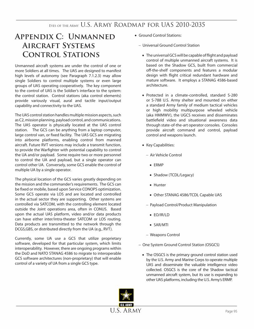
Eyes of the Army U.S. Army Roadmap for UAS 2010-2035
U.S. Army Page 95
Appendix C: Unmanned Aircraft Systems Control Stations
Unmanned aircraft systems are under the control of one or more Soldiers at all times. The UAS are designed to manifest high levels of autonomy (see Paragraph 7.1.2.3) may allow single Soldiers to control multiple systems or even large groups of UAS operating cooperatively. The key component to the control of UAS is the Soldier’s interface to the system: the control station. Control stations (aka control elements) provide variously visual, aural and tactile input/output capability and connectivity to the UAS.
The UAS control station handles multiple mission aspects, such as C2, mission planning, payload control, and communications. The UAS operator is physically located at the UAS control station. The GCS can be anything from a laptop computer, large control van, or fixed facility. The UAS GCS are migrating into airborne platforms, enabling control from manned aircraft. Future RVT versions may include a transmit function, to provide the Warfighter with potential capability to control the UA and/or payload. Some require two or more personnel to control the UA and payload, but a single operator can control other UA. Conversely, some GCS enable the control of multiple UA by a single operator.
The physical location of the GCS varies greatly depending on the mission and the commander’s requirements. The GCS can be fixed or mobile, based upon Service CONOPS optimization. Some GCS operate via LOS and are located and controlled in the actual sector they are supporting. Other systems are controlled via SATCOM, with the controlling element located outside the Joint operations area, often in CONUS. Based upon the actual UAS platform, video and/or data products can have either inter/intra-theater SATCOM or LOS routing. Data products are transmitted to the network through the DCGS,GBS, or distributed directly from the UA (e.g., RVT).
Currently, some UA use a GCS that utilize proprietary software, developed for that particular system, which limits interoperability. However, there are ongoing programs within the DoD and NATO STANAG 4586 to migrate to interoperable GCS software architectures (non-proprietary) that will enable control of a variety of UA from a single GCS type.
• Ground Control Stations:
− Universal Ground Control Station
• The universal GCS will be capable of flight and payload control of multiple unmanned aircraft systems. It is based on the Shadow GCS, built from commercial off-the-shelf components and features a modular design with flight critical redundant hardware and mature software. It employs a STANAG 4586-based architecture.
• Protected in a climate-controlled, standard S-280 or S-788 U.S. Army shelter and mounted on either a standard Army family of medium tactical vehicles or high mobility multipurpose wheeled vehicle (aka HMMWV), the UGCS receives and disseminates battlefield video and situational awareness data through state-of-the-art operator consoles. Consoles provide aircraft command and control, payload control and weapons launch.
• Key Capabilities:
− Air Vehicle Control
• ERMP
• Shadow (TCDL/Legacy)
• Hunter
• Other STANAG 4586/TCDL Capable UAS
− Payload Control/Product Manipulation
• EO/IR/LD
• SAR/MTI
− Weapons Control
− One System Ground Control Station (OSGCS)
• The OSGCS is the primary ground control station used by the U.S. Army and Marine Corps to operate multiple UAS and disseminate the valuable intelligence video collected. OSGCS is the core of the Shadow tactical unmanned aircraft system, but its use is expanding to other UAS platforms, including the U.S. Army’s ERMP.

Eyes of the Army U.S. Army Roadmap for UAS 2010-2035
U.S. ArmyPage 96
• The OSGCS receives and disseminates battlefield video through state-of-the-art aircraft operator and payload operator terminals, as well as mission planning consoles. Its design also complies with NATO STANAG 4586, enhancing interoperability among international military forces by supporting the operation of numerous allied UAS.
• Shadow OSGCS is reconfigurable for use with any UAS. It is designed with commercial off-the-shelf components and features a modular design with redundant hardware, a UNIX-based operating system, and mature software. Protected in a climate-controlled, standard S-788 U.S. Army shelter, the Shadow OSGCS receives and disseminates battlefield video and situational data.
• Protected in a climate-controlled, standard S-280 U.S. Army shelter and mounted on a standard Army five-ton medium tactical vehicle, the ERMP OSGCS receives and disseminates battlefield video and situational awareness data through state-of-the-art operator consoles. These consoles support aircraft C2, payload control, and weapons launch.
− The One System Portable Ground Control Station (OSPGCS). The OSPGCS performs all functions of the full OSGCS in a smaller package. The OSPGCS enables remote launch and recovery operations, freeing the OSGCS for operations at tactical operations centers or forward operating bases.
− One Station Remote Video Terminal (OSRVT). The OSRVT delivers real-time surveillance directly to the Soldier. The OSRVT’s innovative, modular video and data system enables Soldiers to remotely downlink live surveillance images and critical geo-spatial data directly from joint unmanned aircraft systems (such as Shadow, Hunter, Pioneer, Raven, Predator, Aerosonde, and Sky Warrior), as well as from manned platforms.
− Centralized Controller. The centralized controller is a handheld control device for control of Class I UAS and ground robotics. The device supports tether (UGV only) and wireless control of robotics and limited planning activities. The device also provides situational awareness to the operator, laser designator interface as well as live, computer-based and virtual training capability.

Eyes of the Army U.S. Army Roadmap for UAS 2010-2035
U.S. Army Page 97
Appendix D: UAS Organizations
• MQ-1C ERMP Organization − Battalion organization organic to Combat Aviation Brigade • First fielded as companies to all divisions and will
grow to battalion organization over time− 12 ERMP UAS− Four ground control sections • Centralized planning / launch / recovery /
maintenance • Decentralized mission execution
1/11/116//128
CompanyHQ
CompanyHQ
1/1/7//9
FlightOperations
Section
0/3/4//7
CompanySupplySection
0/0/2//2
Auto MaintRepairSection
0/0/17//17
FieldFeedingSection
0/0/5//5
III / VSection
0/0/6//6
FlightPlatoon
1/4/41//46 0/6/45//51
Flight PLTHQ
0/1/1//2
0/4/36//40Ground CtrlSection (x4)
MaintenancePlatoon
0/1/30//31
MaintenancePlatoon HQ
0/1/5//6
ER/MP UASMaintenanceSection (x2)
0/0/20//20
UAS AVIMAugmentation
Section
0/0/5//5Launch &RecoverySection
0/1/8//9
Figure D‑1 UAS Organizations

Eyes of the Army U.S. Army Roadmap for UAS 2010-2035
U.S. ArmyPage 98
1 AD
QRC 1 QRC 2
FY12 FY13 FY14 FY15 FY162
?
1 2FY17FY09 FY10 FY11
2 341FY09 FY10
412 3 3 1 241 2 3 3FY11 FY12
1 2 3 441 2 4 4 1 23 4 1 2 1 2
3
FY173 43
FY13 FY14 FY15 FY16
1 312 3 4 4 1 22 31 2 3 4 4 3 44 1 2 32 3 4 1 4 1 2 341
1 AD 1 CAV 1 ID 3 ID 82 ABN 101 ABNAV SOF AV SOF AV SOF
Figure D‑2 MQ‑1C ERMP Fielding Schedule

Eyes of the Army U.S. Army Roadmap for UAS 2010-2035
U.S. Army Page 99
• The RQ-7B Shadow aerial reconnaissance platoon consists of:
0/2/20//22
0/2/1//3PLATOONHQ
0/0/9//9MISSION PLNG
& CONTROL SECTION
0/0/10//10LAUNCH & RECOVERYSECTION
SHADOW TUAS PLT (Standard Design)
0/2/25//27
0/2/1//3PLATOONHQ
0/0/9//9MISSION PLNG
& CONTROL SECTION
0/0/15//15LAUNCH & RECOVERYSECTION
SHADOW TUAS PLT (+5) Personnel from BCT Holistic Review for BCTs Only
Figure D‑3 Shadow TUAS PLT

Eyes of the Army U.S. Army Roadmap for UAS 2010-2035
U.S. ArmyPage 100
1/5/41//47
GN CTL &OPS PLT
COMPANYHQ
LAUNCHRECOVERY& SVC PLT
GN CTL & OPS PLT HQ
MISSION PLANNINGSECTION
LAUNCH RECOVERY &SVC PLT HQ
LAUNCH & RECOVERYSECTION
1/1/5//7 0/2/14//16 0/2/22//24
0/1/1//2
0/1/5//6
0/1/2//3
0/0/6//6
GROUNDCONTROLSECTION
0/0/8//8SERVICE &SUPPORTSECTION
0/1/14//15
Figure D‑4 Hunter Aerial Reconnaissance Company
• The Hunter aerial reconnaissance company organization consists of:

Eyes of the Army U.S. Army Roadmap for UAS 2010-2035
U.S. Army Page 101
IHQ
IBCT
MI
I
I
II
BSTB
HHC
I
I
II
I
HHT
I
I
I
HHC
II
I
I
W
HHB
I
II
I
II
BSB
I
HHC
I
I
I
4 MASTER TRAINERS (MT)2 MASTER TRAINERS/OPERATORS (OP)28 OPERATORS
X
1 SUAS2 SUAS
1 MT/OP1 OP
1 MT/OP1 OP
1 MT4 OP
1 MT
4 OP
4 SUAS(8)
1 MT16 OP
1 MT
6 OP
2 OP
3 SUAS
1 MT6 OP
1 MT
4 OP
2 OP
1 SUAS
1 MT/OP1 OP
1 MT/OP1 OP
NOTE: BSTB & BSB – One Position is both Master Trainer & Operator
OP = OperatorMT = Master Trainer
Small UAVS
15 SUA S (45 Air Vehicles)
Figure D‑5 IBCT SUAS Distribution & Positions
• A Raven team typically consists of: − Two operators from the unit assigned the equipment− Three UA− Three payload types• EO front and side look (quantity of three) • IR front look (quantity of two)• IR side look (quantity of two)
− One ground control unit (GCU)− RVT− Batteries (rechargeable)− Carry/protective cases− Battery charger/power supply− Field maintenance kit− Spares and repair parts
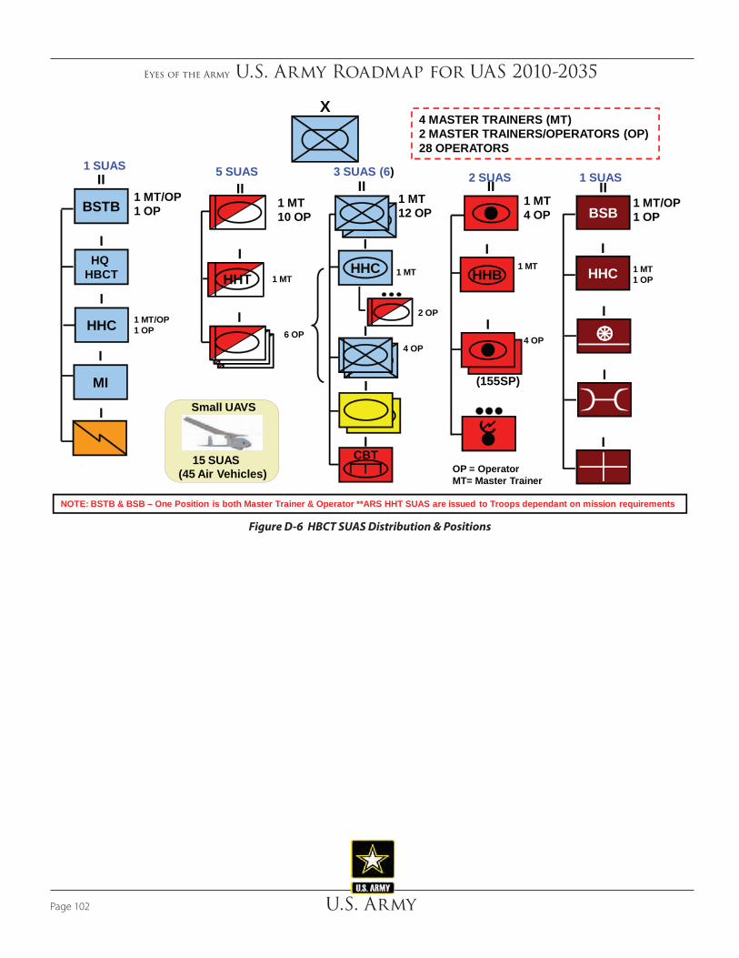
Eyes of the Army U.S. Army Roadmap for UAS 2010-2035
U.S. ArmyPage 102
X
ICBT
2 SUAS1 SUAS 5 SUAS 3 SUAS (6) 1 SUAS
II
I
HHT
I
II
I
I
I
HHC
II
I
(155SP)
HHB
I
II
BSB
I
HHC
I
I
I
1 MT/OP1 OP 1 MT
10 OP
6 OP
1 MT12 OP
4 OP
1 MT4 OP
4 OP
1 MT1 OP
1 MT/OP1 OP
1 IO
2 OP
1 MT1 MT 1 MT
OP = OperatorMT= Master Trainer
NOTE: BSTB & BSB – One Position is both Master Trainer & Operator **ARS HHT SUAS are issued to Troops dependant on mission requirements
1 MT/OP1 OP
IHQ
HBCT
II
BSTB
HHC
I
MI
I
I
4 MASTER TRAINERS (MT)2 MASTER TRAINERS/OPERATORS (OP)28 OPERATORS
Small UAVS
15 SUA S (45 Air Vehicles)
Figure D‑6 HBCT SUAS Distribution & Positions

Eyes of the Army U.S. Army Roadmap for UAS 2010-2035
U.S. Army Page 103
Figure D‑7 SBCT SUAS Distribution & Positions
X
3 SUAS
1 MT6 OP
I
II
I
I6 OP
II3 SUAS(9)
I
I
HHC
1 MT18 OP
6 OP
II
BSB
I
HHC
I
I
I
3 SUAS
HSB
I
II
I
(155T)
1 MT6 OP
I
MI
I
I
I
IHHC
SBCT
1 SUAS
1 SUAS
1 MT/OP1 OP
1 MT1 MT
1 MT
OP = OperatorIO = Instructor Operator
NOTE: BSTB, FIRES, & BSB – One Position is both Master Trainer & Operator
3 MASTER TRAINERS2 MASTER TRAINERS/OPERATORS28 OPERATORS
1 MT/OP1 OP
1 MT/OP1 OP
6 OP
HHT
Small UAVS
**17 SUA S (51 Air Vehicles)

Eyes of the Army U.S. Army Roadmap for UAS 2010-2035
U.S. ArmyPage 104
Figure D‑8 ACR SUAS Distribution & Positions
Small UAVS to Troop Level
**17 SUA S Systems (51 Air Vehicles)
MI
I
II
SPT
I
HHT
I
I
I
5 SUASPer
Squadron
I II
I
I
I
I
(155SP)
I I I
ICBT
I
I
II
IHHT
IUL
IR
I
1 MT
6 OP (2/Troop)
2 OP
2 OP
1 MT
1 MT10 OP each Squadron
1 MT/OP1 OP1 MT/OP
1 OP
1 MT/OP1 OP1 MT/OP
1 OP
2 MASTER TRAINERS2 MASTER TRAINERS/OPERATORS32 OPERATORS
OP = OperatorMT = Master TrainerMT/OP = Master Trainer & Operator
1 SUAS1 SUAS
HHT
HHT

Eyes of the Army U.S. Army Roadmap for UAS 2010-2035
U.S. Army Page 105
Appendix E: Unmanned Aircraft System Challenges & Gaps
E.1 Unmanned Aircraft System Airspace Integration
E.1.1 Overview
The Army vision is to have “file and fly” access for appropriately equipped UAS by the end of 2012 while maintaining an equivalent level of safety (ELOS) to aircraft with a pilot onboard. For military operations, UAS will operate with manned aircraft in civil airspace, including in and around airfields, using CONOPS that make on- or off-board distinctions transparent to air traffic control (ATC) authorities and airspace regulators. The OPTEMPO at mixed airfields diminishes with the integration of UAS.
Historically, the Army in support of combat operations in military controlled airspace predominately operated UAS; however, UAS support to civil authorities (Joint Task Force Katrina in 2005, U.S. Border surveillance, and fire suppression) continues to expand. This expansion highlights the need for routine access to the NAS outside of restricted and warning areas, over land and water. Additionally, operating UAS in host nation airspace emphasizes the need to resolve airspace integration concerns as soon as practical.
E.1.2 Background
Because current UAS do not have the same capabilities to integrate into the NAS as manned aircraft, the FAA grants access to operate outside of restricted and warning areas on a case-by-case basis. A process used to gain NAS access was jointly developed and agreed to by the DoD and FAA in 1999. Military operators of UAS are required to obtain a COA from the FAA. The process can take up to 60 days and because UAS do not have a SAA capability, may require chase planes and/or primary radar coverage. UAS units submit COAs for approval annually; but they are limited to specific routes or areas.
With a COA, the UAS can fly in the NAS when mission needs dictate; however, the FAA segregates the UAS from manned
aviation because the UAS lacks the ability to meet the same regulatory requirements as a manned aircraft. An exception is the integration of UAS flying on instrument flight rules (IFR) flight plans. As the DoD CONOPS for UAS matures and as the Army ensures the airworthiness of our UAS, we will look toward developing new procedures to gain access to the NAS. Toward that end, the Army is working through DoD with the FAA to refine and/or replace the COA process to enable more ready access to the NAS for qualified UAS.
The Army must address three critical issues in order to supplant the COA process: UAS reliability, FAA regulations, and an SAA capability. The OSD and FAA, working through the DoD Policy Board on federal aviation are engaged in establishing the air traffic regulatory infrastructure for integrating military UAS into the NAS. By limiting this effort’s focus to traffic management of domestic flight operations by military UAS, the hope is to establish a solid precedent that extends to other public and civil UAS domestically and to civil and military flights in international and non-U.S. airspace. This initiative serves as the first brick in the larger, interwoven wall of regulations governing worldwide aviation. Precepts include the following:
• Do no harm. Avoid new initiatives, e.g., enacting regulations for the military user that would adversely af-fect the military departments’ right to self-certify aircraft and aircrews, ATC practices or procedures, or manned aviation CONOPS or TTPs that would unnecessarily restrict civilian or commercial flights. Where feasible, leave “hooks” in place to facilitate the adaptation of these regulations for civil use. This applies to recognizing that “one size does not fit all” when it comes to establishing regulations for the wide range in size and performance of Army UAS.
• Conform rather than create. Apply the existing Title 14 CFR (formerly known as Federal Aviation Regu-lations, or FARs) to also cover unmanned aviation and avoid the creation of dedicated UAS regulations as much as possible. The goal is to achieve transparent flight operations in the NAS.
• Establish the precedent. Although focused on domestic use, any regulations enacted will likely lead, or certainly have to conform to, similar regulations govern-ing UAS flight in International Civil Aviation Organization (ICAO) and foreign domestic (specific countries’) airspace. Significant progress in UAS reliability, regulation, and an SAA capability must happen before the vision of “file and fly” can occur.

Eyes of the Army U.S. Army Roadmap for UAS 2010-2035
U.S. ArmyPage 106
E.1.2.1 Reliability
The UAS reliability is the first hurdle in airspace considerations because it underlies UAS acceptance into civil airspace, whether domestic or foreign. Historically, UAS have suffered mishaps at one to two orders of magnitude greater than the rate (one loss per 100,000 hours) incurred by manned military aircraft. In recent years, however, flight experience and improved technologies have enabled UAS to continue improve reliability approaching an equivalent level as to their manned military counterparts. Airworthiness teams will develop rigorous standards and greater redundancy designed into the systems as further improvements in reliability occur, e.g., the MQ-1C ERMP and MQ-9A Reaper flight management systems.
E.1.2.2 Regulation
E.1.2.2.1. Air Traffic Operations
The FAA’s air traffic regulations ensure all of the aircraft flown in the NAS operate safely and pose a minimal hazard to people or property on the ground or in the air. The FAA’s focus is on the day-to-day operation and the safe, expeditious movement of air traffic. Time, altitude, and lateral distance define aircraft separation. Additionally, classes of airspace exist that include specific requirements for aircraft equipage, pilot qualifications, and flight plan filing. Regardless of the class of airspace in which aircraft are operating, pilots are required to S&A other air traffic. This requirement exists even when ground controllers provide traffic advisories or when an onboard collision avoidance system, such as the Traffic Alert and Collision Avoidance System (TCAS), is required. SAA is a key issue for allowing UAS into NAS. Figure E-1, NAS
• Ground-based means of enabling the UAS to safely maneuver through the NAS:– Detecting airborne traffic – Providing necessary intelligence to UAS for “Sense and Avoid (SAA)” – Prove GBSAA is a safe alternate means of compliance to FAA “see and avoid” regulation with
rigorous safety analysis/process• GBSAA system includes all available sensors, correlation, fusion, communications,
networks, logic, procedures and user interfaces• Goal is to meet DoD UAS mission requirements
– Collaboration with all services, all UAS operational units, multiple government agencies, industry partners, and academia
– Integrate GBSAA into future systems (including Airborne Sense And Avoid (ABSAA) and NextGen)
Routine Access
Air Worthiness Certification
Sense and AvoidPilot Certification
Equipage
OPS STDS & Procedures
Capability GapsFrom UAS JCOE CBA/ICD
Figure E‑1 NAS UAS Access Capability Gaps
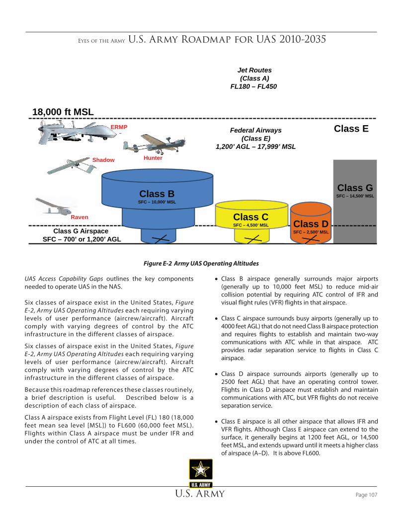
Eyes of the Army U.S. Army Roadmap for UAS 2010-2035
U.S. Army Page 107
UAS Access Capability Gaps outlines the key components needed to operate UAS in the NAS.
Six classes of airspace exist in the United States, Figure E-2, Army UAS Operating Altitudes each requiring varying levels of user performance (aircrew/aircraft). Aircraft comply with varying degrees of control by the ATC infrastructure in the different classes of airspace.
Six classes of airspace exist in the United States, Figure E-2, Army UAS Operating Altitudes each requiring varying levels of user performance (aircrew/aircraft). Aircraft comply with varying degrees of control by the ATC infrastructure in the different classes of airspace.
Because this roadmap references these classes routinely, a brief description is useful. Described below is a description of each class of airspace.
Class A airspace exists from Flight Level (FL) 180 (18,000 feet mean sea level [MSL]) to FL600 (60,000 feet MSL). Flights within Class A airspace must be under IFR and under the control of ATC at all times.
• Class B airspace generally surrounds major airports (generally up to 10,000 feet MSL) to reduce mid-air collision potential by requiring ATC control of IFR and visual flight rules (VFR) flights in that airspace.
• Class C airspace surrounds busy airports (generally up to 4000 feet AGL) that do not need Class B airspace protection and requires flights to establish and maintain two-way communications with ATC while in that airspace. ATC provides radar separation service to flights in Class C airspace.
• Class D airspace surrounds airports (generally up to 2500 feet AGL) that have an operating control tower. Flights in Class D airspace must establish and maintain communications with ATC, but VFR flights do not receive separation service.
• Class E airspace is all other airspace that allows IFR and VFR flights. Although Class E airspace can extend to the surface, it generally begins at 1200 feet AGL, or 14,500 feet MSL, and extends upward until it meets a higher class of airspace (A–D). It is above FL600.
Class A
Class E
Class GSFC – 14,500’ MSL
Class DSFC – 2,500’ MSL
Class CSFC – 4,500’ MSL
Class BSFC – 10,000’ MSL
Federal Airways(Class E)
1,200’ AGL – 17,999’ MSL
Jet Routes(Class A)
FL180 – FL450
60,000 ft MSL
18,000 ft MSL
Class G Airspace SFC – 700’ or 1,200’ AGL
ERMP
HunterShadow
Raven
Figure E‑2 Army UAS Operating Altitudes

Eyes of the Army U.S. Army Roadmap for UAS 2010-2035
U.S. ArmyPage 108
• Class G airspace (there is no Class F airspace in the United States) is also called “uncontrolled airspace” because ATC does not control aircraft there (ATC will provide advisories upon request, workload dependent.). Class G airspace can extend to 14,499 feet MSL, but generally exists below 1200 feet AGL and below Class E airspace.
Accordingly, Classes B, C, and D relate to airspace surrounding airports (terminal airspace) where increased mid-air collision potential exists; Classes A, E, and G primarily relate to altitude and the nature of flight operations that commonly occur at those altitudes (en route airspace). ATC provides separation services and/or advisories to all flights in Classes A, B, and C. They provide it to some flights in Class E and do not provide service in Class G. Regardless of the class of airspace, or whether ATC provides separation services, pilots are required to S&A other aircraft during visual flight conditions.
Unmanned aircraft systems require some taxonomy to define their operating privileges, airworthiness standards, operator training and certification requirements, and place in the right of- way rules. Although public (e.g., U.S. military) aircraft are, to some degree, exempt from a number of FAA regulations such as airworthiness and pilot certification, certain responsibilities still exist:
• UAS must meet equivalent airworthiness and operator qualification standards to operate in the NAS,
• UAS must conform to FAA traffic regulations (SAA, lighting, yielding right-of-way) when operating outside of restricted airspace, and
• UAS must comply with the ICAO regulations when transiting member nation airspace.
• Military UAS that routinely operate outside of restricted airspace or in international airspace must make themselves
Tng Base
Germany
Ft Irwin30th HvyNC NG
NGBMMF
SB6PA NG
1/34IBCT(MN)
58IBCT(MD)
Pax River
Korea173rd
2CR
SB x 3
1StFt Knox
Ft Drum
Ft Campbell
Ft Hood
Ft Lewis
Ft Carson
Ft Bliss
Ft Riley
Ft Wainwright
Ft Richardson Schofield Barracks
4ID
SB325th
25th 25th
10MN
1CAV
3ACR 4 ID1 CAV
Ft Benning
Ft Stewart
Ft Bragg82nd
3 ID
3 ID
101ST
Ft Polk10 MN
1AD
2ID
1ID
1ID
Δ Ft. Huachuca
Italy
278HBCT(TN)
11 ACR NTC
81HBCT(WA)
256HBCT(LA)
76IBCT(IN)
37IBCT(MI)
39IBCT(AR)
45IBCT(OK)
56IBCT(TX)
50IBCT(NJ)
33IBCT(IL)
86IBCT(CO)
116HBCT(ID)
41IBCT(OR)
26IBCT(MA)
NG(AL)
155HBCT(MS)
53IBCT(FL)
149IBCT(KY)
32IBCT(WI)
NG(UT)
29IBCT(HI)
48IBCT(GA)
2/34IBCT(IA)
116IBCT(VA)
27IBCT(NY)
55HBCT(PA)
218HBCT(SC)
72IBCT(TX)
2/28HBCT(PA)
207IBCT(AK)
81st HBCTWA NG
40IBCT(CA)
UAECENTCOM
Navy Pax River
BEALEAFB
El Mirage,CA
• Army Active & NG UAS State Assets through FY15
• Marine UAS Locations
• Airforce/Navy UAS Locations
MCB, VMU-1
MCAS, VMU-2
MCBMCB
MCBOkinawa
Figure E‑3 Worldwide Joint UAS Usage

Eyes of the Army U.S. Army Roadmap for UAS 2010-2035
U.S. Army Page 109
ELOS compliant to air traffic management authorities. In large part, this means conforming by waiver to 14 CFR 91 for the larger UAS, such as the ERMP. These UAS (Cat III) will be equipped and trained similar to manned aircraft.
Figure E-3, Worldwide Joint UAS Usage, depicts the worldwide stationing of Joint UAS assets and the national challenge of integrating military UAS operations within the civilian aviation environment.
The FAA has approved a Light Sport Aircraft (LSA) category in the regulations and does not require either airworthiness or pilot certification (similar to Part 103 aircraft) uses or limited operations. These aircraft achieve an equivalent level of safety to certificated aircraft with a slightly lower level of reliability. Many restricted category aircraft perform special purpose operations. The Army’s RQ-7 Shadow and MQ-5 Hunter share similar characteristics and performance. This plan calls for some UAS to be equivalent to ultra-lights, LSA, or restricted category aircraft.
As a final case with application to UAS, the FAA has chosen not to explicitly regulate certain other aircraft, such as model rockets, fireworks, and radio-controlled (RC) model aircraft. Title 14 CFR 101 specifically exempts smaller balloons, rockets, and kites from the regulation; and FAA Advisory Circular 91-57 addresses RC model airplanes, but is advisory only. These systems are absent from the regulations. The Army currently employs UAS in the same SWaP regimes as those of RC models (e.g., Raven). This plan compares SUAS similar to RC model aircraft. This discussion provides divisions for all military UAS.
The FAA is moving toward a two-class structure for the NAS: “terminal” and “en route.” Terminal will subsume Class B, C, and D airspace, and en route will include Class A, E, and G airspace.
The FAA categorizes UAS into three categories as defined here:
• UAS (Cat III). Capable of flying throughout all categories of airspace and conforms to Part 91 (i.e., all the things a regulated manned aircraft must do including the ability to SAA). Airworthiness certification and operator qualification are required. Global Hawk and Predator are examples of UAS built for beyond LOS operations.
• UAS (Cat II). Non-standard aircraft that perform special purpose operations. Shadow operators must provide evidence of aircraft airworthiness and
operator qualification. Cat II UAS may perform routine operations within a specific set of restrictions.
• UAS (Cat I). Analogous to RC models as covered in Advisory Circular 91-57. Operators must provide evidence of airworthiness and operator qualification. Small UAS are generally limited to visual LOS operations and altitude restrictions. Examples include Raven, Wasp and Dragon Eye.
E.1.2.2.2 Airworthiness Certification
The FAA’s airworthiness regulations ensure that aircraft will minimize their hazard to aircrew, passengers, people, and property on the ground. Airworthiness is concerned with the material and construction integrity of the individual aircraft and the prevention of the aircraft coming apart in mid-air and/or causing damage to persons or property on the ground. Over the 19-year period from 1982 to 2000, an annual average of 2.2 percent of all aviation fatalities involved people hurt from parts falling off aircraft. A UAS that must be available for unrestricted operations worldwide in most classes of airspace compels serious consideration for the safety of people on the ground. The operational requirements for UAS operation in civil airspace means flight over populated areas must not raise concerns based on overall levels of airworthiness; therefore, UAS standards cannot vary widely from those for manned aircraft without raising public and regulatory concern.
FAA regulations do not require “public aircraft” (government-owned or -operated) to be certified airworthy to FAA standards. Most nonmilitary public aircraft are versions of aircraft previously certified for commercial or private use; however, the only public aircraft not related to FAA certification standards in some way are usually military aircraft. These aircraft go through the military’s internal airworthiness certification/flight release process. A tri-service memorandum of agreement describes the responsibilities and actions associated with mutual acceptance of airworthiness certifications for manned aircraft and UAS within the same certified design configuration, envelope, parameters, and usage limits certified by the originating military department.
Defined in Figure E-4 are the three levels of airworthiness. Level 1 certifies to standards equivalent to manned systems tailored for UAS with catastrophic failure rates no worse than one loss per 100,000 flight hours. Level 2 authorizes to standards less stringent that manned

Eyes of the Army U.S. Army Roadmap for UAS 2010-2035
U.S. ArmyPage 110
systems with catastrophic failure rates no worse than one loss per 10,000 flight hours. Level 2 is the minimum level for weaponization. Level 3 authorizes UAS to a minimum acceptable level of safety with catastrophic failure rates no worse than one per 1,000 flight hours.
E.1.2.2.3 Crew Qualifications
The FAA’s qualification standards (14 CFR 61, 63, 65, and 67) ensure the competency of aircrew and aircraft maintainers. As in the case of airworthiness certification, these CFR parts do not pertain to military personnel certified in a similar, parallel process. The DoD and FAA have signed a memorandum of agreement through which DoD agrees to meet or exceed civil training standards, and the FAA agrees to accept military-rated pilots into the NAS. These factors indicate that a certain minimum knowledge standard is required of all pilots-in-command in order to operate aircraft in the NAS. In order to meet the intent of “do no harm,” training for Cat III aircraft they would include, but not be limited to:
• Regulations
• Airspace clearances and restrictions
• Aircraft flight rules
• Air traffic communications
• Aircraft sequencing and prioritization
• Take-off and landing procedures for combined manned and unmanned operations
• Go-around and abort procedures
• Flight planning and filing (including in-flight filing)
• Flight and communications procedures for lost link
• Weather reporting and avoidance
• Ground operations for combined manned and unmanned operations
• Flight speed and altitude restrictions, and, when applicable
• Weapons carriage procedures (including hung ordinance flight restrictions)
Under the international doctrine for public aircraft, the FAA does not have to agree with DoD training or accept military ratings; the military departments are entitled to make these judgments independently. The Army identifies what and how it will operate and create the training programs necessary to accomplish its missions safely. Some of the UAS-related training is a fundamental shift away from the skills needed to fly a manned aircraft (e.g., ground-based visual landing). These differences can relate to the means of landing: visual remote, aided visual, or fully autonomous. They also may relate to different interface designs for the UAS functions or the level of control needed to exercise authority over an aircraft based
VehicleSize
General Guidance Airspace
Max Wt
(lbs)
Max Speed(kts)
International &National
Active Restricted& Combat Zones
Expendable UA in Active Restricted (per RCC 323-99)
Med/Large >1320 >200 1 2 3
Light Up to 1320 200 1 2 3
Small / Mini /Micro
Up to 55 120
COA Process(Addressed on case-
by-case basis)3 3
Figure E‑4 Levels of Airworthiness

Eyes of the Army U.S. Army Roadmap for UAS 2010-2035
U.S. Army Page 111
on its autonomous capability. As a result, the Army must have minimum standards for knowledge skills required of UAS operators operating in the NAS. This minimum standard may differ for given classes of UAS. Unmanned aircraft system operators will conform to these requirements.
E.1.2.3 “Sense and Avoid” Principle
Because military UAS will increasingly operate outside of special use airspace, UAS-related military technology and regulations must be sensitive to other airspace users. Coordination of both domestic and international airspace efforts conducted in parallel to the OSD-FAA effort is necessary. These efforts are not only leveraging previous accomplishments of the OSD-FAA effort, but are contributing to it on technical and regulatory levels. Such efforts in the commercial and civil arenas reduce the burdens that accompany the successful integration of military UAS into the NAS by facilitating technology development, common UAS standards/airworthiness, cost-effectiveness, reliability, and public acceptance.
SAA is the ability of a UAS to remain well clear from and avoid collisions with other airborne traffic. SAA provides the intended functions of self-separation and collision avoidance as a means of compliance with regulatory requirements to “see and avoid” compatible with expected behavior of aircraft operating in the airspace system. An SAA capability would perform the sub functions of detecting, tracking, evaluating, prioritizing, declaring, determining an action, and commanding the determined action. One possible solution to the SAA gap is GBSAA. The GBSAA is a ground-based means of detecting airborne traffic and providing the necessary intelligence to the UAS to allow it to SAA, as an alternate means of compliance with the FAA regulations to “see and avoid”. This will enable the UAS to safely maneuver the unmanned aircraft through the national airspace. The system includes all available sensors, fusion, communications, networks, procedures, maneuver algorithms and user interfaces. Operators will employ GBSAA to facilitate operation within the NAS in non-segregated airspace for the full spectrum of UAS mission requirements and integrate GBSAA into future systems supporting all UAS operational units, multiple government agencies, industry partners, and academia.
A key requirement for routine access to the NAS is UAS compliance with 14 CFR 91.113, “Right-of-Way Rules: Except Water Operations.” This section contains the phrase “sense and avoid” and is the primary restriction to normal
operations of UAS. The intent of S&A is for pilots to use their sensors (eyes) and other tools to find and maintain situational awareness of other traffic and to yield the right-of-way, in accordance with the rules, when there is a traffic conflict. Since the purpose of this regulation is to avoid mid-air collisions, this should be the focus of technological efforts to address the issue as it relates to UAS rather than trying to mimic and/or duplicate human vision. In June 2003, the U.S. Air Force’s Air Combat Command sponsored a joint working group to establish and quantify an SAA system capability for submission to the FAA. Released in June 2004, the title of their white paper was S&A Requirement for Remotely Operated Aircraft.”
Relying on human vision results in mid-air collisions accounting for an average of 0.8 percent of all mishaps and 2.4 percent of all aviation fatalities incurring annually (based on the 3- year average from 1998 to 2000). Meaningful SAA performance must alert the UAS operator to local air traffic at ranges sufficient for reaction time and avoidance actions by safe margins.
Furthermore, UAS operations BLOS may require an automated SAA system due to potential communications latencies or failures. The FAA does not provide a quantitative definition of SAA, largely due to the number of combinations of pilot vision, collision vectors, sky background, and aircraft paint schemes involved in seeing oncoming traffic. Having a sufficient field of regard for a UAS SAA system, however, is fundamental to meeting the goal of assured air traffic separation.
Although an elusive issue, one fact is apparent. The challenge with the SAA issue is both a capability constraint and a regulatory one. Given the discussions in this and other analyses, a possible definition for SAA systems emerges. Sense and avoid is the onboard, self-contained ability to:
• Detect traffic that may be a conflict
• Evaluate flight paths
• Determine traffic right of way
• Maneuver well clear according to the rules in Part 91.113
The key to providing the “equivalent level of safety” required by FAA Order 7610.4M, “Special Operations,” Chapter 12, Section 9, “UAS Operations in the NAS,” is the provision of some comparable means of S&A provided
Eyes of the Army U.S. Army Roadmap for UAS 2010-2035
U.S. ArmyPage 112
by pilots on board manned aircraft. The purpose of SAA is to avoid mid-air collisions, and this should be the focus of technological efforts to automate this capability, rather than trying to mechanize human vision.
The detection of oncoming traffic and the execution of a maneuver to avoid a mid-air collision divide the SAA capability from a technical perspective. Passive or active techniques applicable in cooperative or non-cooperative traffic environments further subdivide the detection aspect.
The active cooperative scenario involves an interrogator monitoring a sector ahead of the UAS to detect oncoming traffic by interrogating the transponder on the other aircraft. Its advantages are that it provides both range and bearing to the traffic and can function in both visual and instrument meteorological conditions (i.e., visual meteorological conditions [VMC] and instrument meteorological conditions [IMC]). Its disadvantages are its relative cost. Current systems available in this category include the various TCASs.
The active non-cooperative scenario relies on a radar- or laser-like sensor scanning a sector ahead of the UAS to detect all traffic, whether transponder-equipped or not. The returned signal provides range, bearing, and closure rate and allows prioritization of oncoming traffic for avoidance, in either VMC or IMC. Its potential drawbacks are its relative cost, the bandwidth requirement to route its imagery (for non-autonomous systems), and its weight. An example of an active, non-cooperative system that is currently available is a combined microwave radar and infrared sensor originally developed to enable helicopters to avoid power lines.
The passive cooperative scenario, like the active cooperative one, relies on everyone having a transponder that broadcasts position, altitude, and velocity data. Its advantages are its lower relative cost (no onboard interrogator required to activate transponders) and its ability to provide SAA information in both VMC and IMC. Its disadvantage is its dependence on all traffic carrying and continuously operating transponders. In this scenario, UAS should have the capability to change transponder settings while in flight.
The passive non-cooperative scenario is the most demanding one. It is also the most analogous to the human eye. An SAA system in this scenario relies on a sensor to detect and provide azimuth and elevation to
the oncoming traffic. Its advantages are its moderate relative cost and ability to detect non-transponder-equipped traffic. Its disadvantages are its lack of direct range or closure rate information, potentially high bandwidth requirement (if not autonomous), and its probable inability to penetrate weather. The gimbaled EO/IR sensors currently carried by reconnaissance UAS are examples of such systems; however, if they are looking at the ground for reconnaissance, then they are not available to perform SAA. An emerging approach that would negate the high bandwidth requirement of any active system is optical flow technology, which reports only when it detects an object showing a lack of movement against the sky, instead of sending a continuous video stream to the ground controller. Imagery from one or more inexpensive optical sensors on the UAS compares the last image by an onboard processor to detect minute changes in pixels, indicating traffic of potential interest.
Once the “detect and sense” portion of SAA is satisfied, the UAS must use this information to execute an avoidance maneuver. The latency between seeing and avoiding for the pilot of a manned aircraft ranges from 10 to 12.5 seconds according to FAA and DoD studies. If relying on a ground operator to SAA, the UAS incurs the same human latency, but adds the latency of the data link bringing the image to the ground for a decision and the avoidance command back to the UAS. This added latency can range from less than a second for LOS links to more time for satellite links.
An alternative is to empower the UAS to autonomously decide whether, and which way to react to avoid a collision once it detects oncoming traffic, thereby removing the latency imposed by data links. Some UAS considered implementing TCAS II, similar to manned aircraft to accomplish SAA since TCAS II already recommends a vertical direction to the pilot, but simulations have found the automated maneuver worsens the situation in a fraction of the scenarios. For this reason, the FAA has not certified automated collision avoidance algorithms based on TCAS resolution advisories; doing so would set a significant precedent for UAS SAA capabilities. The long-term FAA plan is “to move away from infrastructure-based systems towards a more autonomous, aircraft-based system” for collision avoidance. Installation of TCAS is increasing across the aviation community, and TCAS functionality supports increased operator autonomy. Research and testing of Automatic Dependent Surveillance-Broadcast (ADS-B) may afford an even
Eyes of the Army U.S. Army Roadmap for UAS 2010-2035
U.S. Army Page 113
greater capability and affirms the intent of the aviation community to support and continue down this path. By 2020, the FAA will require all UAS to fly with ADS-B. Such equipment complements basic SAA, adds to the situational awareness, and helps provide separation from close traffic in all meteorological conditions.
E.1.3 Command, Control, Communications
E.1.3.1 Data Link Security
In general, there are two main areas of concern when considering link security: inadvertent or hostile interference of the uplink and downlink. The forward (“up”) link controls the activities of the platform itself and the payload hardware. This command and control link requires a sufficient degree of security to ensure that only authorized agents have access to the control mechanisms of the platform. The return (“down”) link transmits critical data from the platform payload to the Warfighter or analyst on the ground or in the air. The UAS operator must receive system health and status information without compromise. Effective EMS allocation and management are critical to reducing inadvertent interference of the data links.
E.1.3.2 Redundant/Independent Navigation
The air navigation environment is changing, in part, because of the demands of increased traffic flow. Reduced allowances for deviation from intended flight paths now exist, that provide another means for increasing air traffic capacity by using reduced separation airways, standard departures and approaches. As tolerances for navigational deviation decrease, the need for precision navigation grows. All aircraft must ensure they have robust navigational means. Historically, the installation of redundant navigational systems provides this robustness. The need for dependable, precise navigation reinforces the redundancy requirements.
While navigation accuracy and reliability pertain to Army operations and traffic management, current systems are achieving the necessary standard without redundancy and without reliance on ground-based navigation aids. The Federal Radio Navigation Plan, signed January 2006, establishes the following national policies:
• Properly certified GPS is a supplemental system for domestic en route and terminal navigation, and for non-precision approach and landing operations.
• The FAA’s phase-down plan for ground-based navigation aid systems (NAVAIDS) retains at least a minimum operational network of ground-based NAVAIDS for the foreseeable future.
• The FAA will maintain sufficient ground-based NAVAIDS to provide airspace users a safe recovery and sustained operations capability in the event of a disruption in satellite navigation service.
These policies apply, as a minimum, to all aircraft flying in civil airspace. With GPS, the prospect for relief of some redundancy requirements in manned aviation may be an option in the future. However, UAS have a diminished prospect for relief since, unlike manned aircraft, a UAS without communication links cannot readily fall back on dead reckoning, contact navigation, and map reading in the same sense that a manned aircraft can.
E.1.3.3 Autonomy
Advances in computer and communications technologies have enabled the development of increasingly autonomous unmanned systems. With the increase in computational power available, developmental UAS are able to achieve improved subsystem, guidance, navigation and control, sensor, and communications autonomy than previous systems. For example, ERMP is designed to identify, isolate, and compensate for a wide range of possible system/subsystem failures and autonomously take actions to ensure system safety. Preprogrammed decision trees address each possible failure during each part of the mission.
Autonomy of UAS refers to the independence of robots from the “hands on” requirement for human involvement in operations. Although there can be many levels of autonomy, there are three basic operational divisions of autonomy commonly used in such discussions – remote operation, semi-autonomous operation and autonomous operation.
Remote operation: This operational mode is most familiar to robotic neophytes. In this mode, a robot controlled by a human operator is functional 100 percent of the time, e.g., a remote control model car. If the robot is out of the physical sight of the human operator, the robot must transmit sensor information (video and robot state vector) to provide the operator the situational awareness necessary to control the

Eyes of the Army U.S. Army Roadmap for UAS 2010-2035
U.S. ArmyPage 114
robot. This is “tele-operation”. In both remote control and tele-operation, the human must instruct the robot during all operations and they represent differences in capability but not level of human involvement.
Semi-autonomous operation: this level of autonomy reduces the need for 100 percent operator control of robot functionality by shifting some sensing, perception and decision-making to the robot. Semi-autonomous movement by a robot requires the human operator to provide a mission plan (consisting of a route of at least two points), guidance as to the robot’s freedom of movement (a corridor) and actions the robot must complete along the route. Semi-autonomous operations allow human operators to monitor operations for periods, thereby achieving reduced workload from remote control. This allows the robot to make some of its own decisions – consistent with the robot design and human-applied constraints. If the robot cannot complete a task within the constraints, it will ask for help from the human operator who then can revert to remote operations. Varied environmental conditions will require more or less human interaction, but the expense and risk of giving the robot more autonomy is justified by the reduction in operator task load and improvements in performance (e.g., semi-autonomous operations permit higher movement speeds than achievable in remote operations).
Autonomous: this level of autonomy further reduces the need for operator control of robot functionality by shifting even more sensing, perception and decision-making to the robot. The intent of this level is to express a significantly reduced need for human interaction. The human must still monitor and provide assistance, but the frequency and duration of periods of tele-operation are significantly reduced allowing human controllers to shift workload elsewhere or control multiple robots. The robot must have a mission plan, but robots executing autonomous operations resolve problems that would require human intervention for a semi-autonomous vehicle. The UGV exhibits increased operational autonomy beyond movement, integrating other functionality with movement and extending decision-making to address moral and ethical issues as well as complicated tactical considerations. Even the highest level of autonomous operation - “full autonomy” - requires human monitoring and communication of mission intent. When fully autonomous, the robot is still a slave to the human and subject to limits of design and mission constraints.
Semi-autonomous operation implies a significantly less level of “robotic independence” than that implied by higher levels autonomy that approach “full autonomy”.
That said, “autonomously” is an adverb often used in the context of differentiating between human-only and machine-aided activity. When “autonomously” is used in conversation and print, the autonomy level of the robot must be clearly understood to avoid miscommunication. It is perfectly acceptable to say, “The unmanned system moved autonomously” when the vehicle actually only has semi-autonomous capability if the robot’s limitations have been previously made clear.”
One of the most difficult aspects of high levels of autonomy is ensuring that all elements remain synchronized. A key accomplishment will be to verify that: 1) the UAS receives all messages; 2) the UAS correctly interprets the messages; and 3) the entire squadron has a single set of mission plans to execute. It is particularly important that increasingly autonomous systems be able to understand commander’s intent and make decisions that always support that intent. This requires proper interpretation of commander’s intent by UAS operators and perhaps modification or standardization of commander’s intent terms to simplify this interpretation.
E.1.3.4 Lost Link
In the event of lost C2 links, Army UAS are typically programmed to react according to a pre-set contingency plan (e.g., to climb to a predefined altitude to attempt to reestablish contact). This “lost link profile” may not be appropriate for operations in the NAS. If contact is not reestablished in a given time, the UAS can be preprogrammed to retrace its outbound route home, fly direct to home, or continue its mission depending upon the contingency plan (or plans) pre-set by the operator. Examination of a lost C2 link scenario illustrates that this communications issue can become a critical UAS failure mode. At present, Army UAS platforms include lost link procedures based upon requirements and acquisition strategies. In order for Army UAS to gain routine, seamless access to the NAS, the DoD needs to develop standard lost link procedures for systems requiring routine access to the NAS. This will provide the FAA with predictable, consistent lost link procedures when working with Army and other service UAS.
Documentation on “No Radio” (NORDO) requirements is in 14 CFR 91.185. Remarkably, most lost C2 link situations bear a striking resemblance to NORDO, and UAS would enhance their predictability by autonomously following the guidance. The one exception to this case is the VFR conditions clause. The UAS, even with an autonomous SAA system, would enhance overall safety by continuing to fly IFR. Should
normal ATC-voice communications fail, the FAA also has the

Eyes of the Army U.S. Army Roadmap for UAS 2010-2035
U.S. Army Page 115
capability to patch airspace users through to the controlling ATC authority by phone.
E.1.4 Future Environment
The migration of the NAS from ground-based traffic control to airborne traffic management, scheduled to occur over the next decade, will have significant implications for UAS. The SAA will become an integrated, automated part of routine position reporting and navigation functions by relying on a combination of ADS-B and GPS. In effect, it will create a virtual bubble, or protected airspace, around each aircraft so that when bubbles contact, the aircraft initiates avoidance. All aircraft will be required to be equipped to the same level, making the unmanned or manned status of an aircraft transparent to both flyers and to the FAA.
Finally, the negative perception that UAS are by nature more dangerous than manned aircraft needs to be countered by recognizing that UAS can provide an equivalent level of safety to manned aircraft and possess the following inherent attributes that contribute to flying safely.
• Many manned aircraft mishaps occur during the take-off and landing phases of flight, when human decisions and control inputs are substantial factors. Robotic aircraft do not take chances; preprogrammed conditions are met or the system either auto-aborts or goes around. This will likely reduce the incidence of mishaps during these phases of flight.
• Since human support systems do not exist, mishaps from failed life support systems will not occur.
• An automated take-off and landing capability reduces the need for pattern work and results in reduced exposure to mishaps, particularly in the area surrounding main operating bases.
• UAS control stations can access resources not available in the traditional cockpit and thus increase the operator’s situational awareness.
• A greater percentage of UAS operator training is accomplished through simulation given the nature of GCSs. Using simulations reduces the need to fly the aircraft and the related exposure to mishaps.
E.1.5 Army Organizations with Roles in UAS Airspace Integration
The Army has a UAS program office responsible for the development and acquisition of UAS capabilities that meet Joint Requirements Oversight Council-validated COCOM needs. Many of the Army UAS in development require access to the NAS and foreign domestic airspace. To coordinate related technology and standards development, Army UAS acquisition program managers engage the tri-service UAS Airspace Integration Point Integrated Process Team (JIPT). The JIPT contains issue focused sub teams and support-focused activity centers, one of which is a standards development activity center. The sub teams are responsible for identifying standards gaps and conducting the necessary activities to modify or develop the standards necessary to integrate Army UAS into the NAS. The activity centers, through the Systems Engineering and Integration Team provide critical requirements analysis, modeling and simulation, test and evaluation integration, and standards validation support functions to the sub teams.
E.2 Defensive Measures
Like manned aircraft, defensive measures (low observable technologies, expanded flight envelopes, increased standoff, and countermeasures) must provide for survivability and extended utility. Offensive capabilities (air-to-air and air-to-ground weapons, developing non-lethal means, and advanced flight controls) must provide for multi-role applications. Additionally, the Army can develop design space gains (potentially hundreds of pounds) and performance opportunities (G-force maneuvers at the design limits of the materials vice the human limits) due to the removal of the human. Advanced airframes, propulsion, and flight controls must continue to extend UAS operations in sub-optimal weather conditions currently requiring mission abort.
E.3 Deployability
Recent exercises and studies indicated current UAS must be pre-positioned, deployable, and self-deployable to be operationally relevant in a rapidly developing situation. Unmanned cargo delivery, containerized systems, and air refueling for larger systems, including lighter than air systems, must provide for mobility solutions rather than taxing existing infrastructure.

Page Left Intentionally Blank
Eyes of the Army U.S. Army Roadmap for UAS 2010-2035
U.S. ArmyPage 116

Eyes of the Army U.S. Army Roadmap for UAS 2010-2035
U.S. Army Page 117
Appendix F: Unmanned Aircraft Systems Stakeholders
OPERATIONAL INPUTS / REQUIREMENTS
CoEs CDIDsFires Aviation
USJFCOM
JUAS CoE
ARCIC CAC/CFID
TCMUAS
PEO Integration
TCM AirSensors
MSCoE
ManeuverUAS CoE
CASCOMSignal Intelligence
ACSIM
IMCOM
DA StaffASA (ALT)
PEO AVN
PM UAS
PM RUS
PM BCTM
AATD
RDECOM
USA
TRADOC
Office Sec Def(AT&L) USAF
USN
USMC
SOCOM
Raven Class I
Shad
owR
Hunte
r
U.S. Army ER/MP
CG, TRADOC
CG, USAACE
Manuever CoE/CDID
Fies CoE/CDID
Maneuver Support CoE/CDIDSignal CoE/CDIDIntelligence CoE/CDIDCASCOM (Sustainment CoE/CDID)
PEO AviationPM UAS
PM BCTM ( Formerly FCS)
PM RUS
AATD
ARL
Traning and Doctrine Command
UA/AAS Integration, Doctrine and TTPsDepth and Simultaneous Attack Battle Lab; UAS Effects Integration, TestingDoctrine and TTPs
Army Space and Signal Integration
UAS Training and Simulation, ISR Battle Lab, TCM Air Sensors
UAS Sustainment
UAS and Mine Detection
Air & Missile Research, Development & Engineering Center ARDEC
Unmanned Aircraft Systems
Brigade Combat Team Modernization
Robotics and Unmanned Sensors
Aviation Applied Technologies Directorate, Manned-Unmanned (MUM) TeamingTest Center, UAS Weaponization
Army Research Lab (APG), Sensor, Flight and Robotics Testing
Army UAS Proponent, Aviation Doctrine, Training, Standardization and Safety, TCM UAS, Air Maneuver Battle Lab, Directorate of Evaluation and Standardization
Figure F‑1 Army UAS Stakeholders

Page Left Intentionally Blank
Eyes of the Army U.S. Army Roadmap for UAS 2010-2035
U.S. ArmyPage 118

Eyes of the Army U.S. Army Roadmap for UAS 2010-2035
U.S. Army Page 119
Appendix G: Acronym ListAcronym Definition
ABCS Army Battle Command System
ABSAA Airborne Sense and Avoid
ACS Aerial Common Sensor
ADA Air Defense Artillery
ADS-B Automatic Dependent Surveillance- Broadcast
AEB Aerial Exploitation Battalion
AGL Above Ground Level
AIS Automated Identification System
AIT Advanced Individual Training
AO Area of Operation
ARFORGEN Army Force Generation
ASE Aircraft Survivability Equipment
ASI Additional Skill Identifier
ASTAMIDS Airborne Surveillance, Target Acquisition and Minefield Detection System
ATC Air Traffic Control
AVIM Aviation Intermediate Level Maintenance
AVUM Aviation Unit-Level Maintenance
BCT Brigade Combat Team
BCTM Brigade Combat Team Modernization
Acronym Definition
BDA Battle Damage Assessment
BDRVT Bi-Directional Remote Video Terminal
BLOS Beyond Line of Sight
C2 Command and Control
C3 Command, Control, and Communication
C4I Command, Control, Communications, Computers, and Intelligence
CAB Combat Aviation Brigade
CAS Close Air Support
CBM Conditioned Based Maintenance
CBRNE Chemical, Biological, Radiological, Nuclear, High Yield Explosives
CBP Customs and Border Patrol
CDR Critical Design Review
CFR Code of Federal Regulations
COA Certificate of Authorization
COE Center of Excellence
COCOM Combatant Commander
CONEMP Concept of Employment
CONOPS Concept of Operations
CONUS Continental United States
COP Common Operating Picture
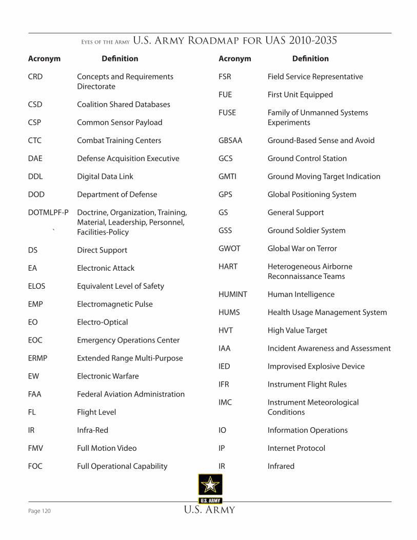
Eyes of the Army U.S. Army Roadmap for UAS 2010-2035
U.S. ArmyPage 120
Acronym Definition
CRD Concepts and Requirements Directorate
CSD Coalition Shared Databases
CSP Common Sensor Payload
CTC Combat Training Centers
DAE Defense Acquisition Executive
DDL Digital Data Link
DOD Department of Defense
DOTMLPF-P Doctrine, Organization, Training, Material, Leadership, Personnel, ` Facilities-Policy
DS Direct Support
EA Electronic Attack
ELOS Equivalent Level of Safety
EMP Electromagnetic Pulse
EO Electro-Optical
EOC Emergency Operations Center
ERMP Extended Range Multi-Purpose
EW Electronic Warfare
FAA Federal Aviation Administration
FL Flight Level
IR Infra-Red
FMV Full Motion Video
FOC Full Operational Capability
Acronym Definition
FSR Field Service Representative
FUE First Unit Equipped
FUSE Family of Unmanned Systems Experiments
GBSAA Ground-Based Sense and Avoid
GCS Ground Control Station
GMTI Ground Moving Target Indication
GPS Global Positioning System
GS General Support
GSS Ground Soldier System
GWOT Global War on Terror
HART Heterogeneous Airborne Reconnaissance Teams
HUMINT Human Intelligence
HUMS Health Usage Management System
HVT High Value Target
IAA Incident Awareness and Assessment
IED Improvised Explosive Device
IFR Instrument Flight Rules
IMC Instrument Meteorological Conditions
IO Information Operations
IP Internet Protocol
IR Infrared

Eyes of the Army U.S. Army Roadmap for UAS 2010-2035
U.S. Army Page 121
Acronym Definition
ISR Intelligence, Surveillance, and Reconnaissance
JCA Joint Capabilities Area
JIIM Joint, Interagency, Intergovernmental, and Multinational
JIM Joint, Interagency, and Multinational
JIPT Joint Integrated Product Team
JUAS COE Joint Unmanned Aircraft System Center of Excellence
LADAR Laser Radar
LCM Life Cycle Management
LOI Level of Interoperability
LOS Line of Sight
LRF/D Laser Range Finder / Designator
LRIP Low Rate Initial Production
LSA Light Sport Aircraft
LSTAT Life Support for Trauma and Transport
LVCG Live, Virtual, Constructive, and Gaming
LZ Landing Zone
MDMP Military Decision Making Process
MEDEVA Medical Evacuation
METL Mission Essential Task List
Acronym Definition
METOC Meteorological and Oceanographic Condition
MOS Military Occupational Specialty
MOSP Multi-Mission Optronic Stabilized Payload
MSL Mean Sea Level
MTI Moving Target Indicator
MTS Multi-Spectral Targeting System
MUM Manned Unmanned Teaming
MUMT-2 Manned Unmanned Teaming – 2
OCO Overseas Contingency Operations
ODIN Observe, Detect, Identify, Neutralize
OEF Operation Enduring Freedom
OIF Operation Iraqi Freedom
OP Observation Post
OPTEMPO Operations Tempo
OPV Optionally Piloted Vehicle
OSD Office of the Secretary of Defense
OSGCS One System Ground Control Station
OSPGCS One System Portable Ground Control Station
OSRVT One System Remote Video Terminal
PBL Performance Based Logistics
PEO Program Executive Office

Eyes of the Army U.S. Army Roadmap for UAS 2010-2035
U.S. ArmyPage 122
Acronym Definition
PIP Product Improvement Plan
POM Program Objective Memorandum
POP Plug-in Optronic Payload
POR Program of Record
QRC Quick Reaction Capability
RAM-T Reliability, Availability, Maintainability, and Testability
RAMS Reliability, Availability, Maintainability, Sustainability
RC Radio Controlled
RDTE Research, Development, Test, and Evaluation
RF Radio Frequency
RSTA Reconnaissance, Surveillance, Target Acquisition
RVT Remote Video Terminal
S&A See and Avoid
SA Situational Awareness
SAA Sense and Avoid
SAM Surface to Air Missile
SAR Synthetic Aperture Radar
SATCOM Satellite Communication
SIGINT Signal Intelligence
SIPRNET Secret Internet Protocol Router Network
Acronym Definition
SOF Special Operations Forces
SRW Soldier Radio Waveform
S&T Science and Technology
STANAG Standardization Agreement
SUAS Small Unmanned Aircraft System
SWaP Size, Weight, and Power
SWARM Smart Warfighting Array of Reconfigurable Modules
TA Target Acquisition
TAC Theater Aviation Command
TADSS Training Aides, Devices, Simulators, Simulations
TCAS Traffic Alert and Collision Avoidance System
TCDL Tactical Common Data Link
TOC Tactical Operations Center
TOE Table of Organization and Equipment
TPED Tasking, Processing, Exploitation, and Dissemination
TRADOC Training and Doctrine Command
TSP Tactical Signal Intelligence Payload
TTP Tactics, Techniques, and Procedures
TUAS Tactical Unmanned Aircraft System
UA Unmanned Aircraft

Eyes of the Army U.S. Army Roadmap for UAS 2010-2035
U.S. Army Page 123
Acronym Definition
UAS Unmanned Aircraft System
UASTB Unmanned Aircraft System Training Battalion
UAV Unmanned Aerial Vehicle
UMS Unmanned System
UGCS Universal Ground Control Station
UGDT Universal Ground Data Terminal
UGS Unattended Ground Sensors
UGV Unmanned Ground Vehicles
USAACE United States Army Aviation Center of Excellence
USSOCOM United States Special Operations Command
VFR Visual Flight Rules
VMC Visual Meteorological Conditions
WAS Wide Area Search
WNW Wideband Network Waveform
ZCA Zero Conflict Airspace

Page Left Intentionally Blank
Eyes of the Army U.S. Army Roadmap for UAS 2010-2035
U.S. ArmyPage 124

Eyes of the Army U.S. Army Roadmap for UAS 2010-2035
U.S. Army Page 125
Appendix H: ReferencesFY2009–2034 Unmanned Systems Integrated Roadmap, Office of Secretary of Defense, 6 April 2009
Sense & Respond Logistics Technology Roadmap, Office of the Deputy Under Secretary of Defense, March 2009
Sense & Respond Logistics: Co-Evolution of an Adaptive Enterprise Capability; DoD Office of Force Transformation, Feb 2004
Unmanned Aircraft System Airspace Integration Plan, Office of the Secretary of Defense, Draft Version 1.7, 30 October 2009
Joint Concept of Operations for Unmanned Aircraft Systems, Joint Requirements Oversight Council, November 2008
Operational Environment 2009-2025, TRADOC, August 2009 (v5)
A Cultural Change, Unmanned Aircraft Systems Training Battalion, 30 November 2008, Captain Shane Boyd, UAS Training Battalion, Fort Huachuca, AZ
Robotics Strategy White Paper, TRADOC, ARCIC, 19 March 2009
Electronic Warfare, Joint Publication 3-13.1, 25 January 2007
Intelligence, FM 2.0, 17, May 2004, Headquarters, Department of the Army (HQDA)
Multi-Service Tactics, Techniques, and Procedures for the Tactical Employment of Unmanned Aircraft Systems, FM 3-04.15, 3 August 2006
Army Unmanned Aircraft System Operations, FM 3-04.155, 14 May 2008
Operations, FM 3-0, 27 February 2008, HQDA
Training for Full Spectrum Operations, FM 7-0, December 2008, HQDA
Army Posture Statement, 2009, HQDA
Army Campaign Plan 2009 (Coordinating Draft), 15 August 2008
The U.S. Army Unmanned Aircraft Systems Strategic Vision 2007, Unmanned Futures Branch, CRD.
The U.S. Army UAS Future’s White Paper, 1 October 2009
PM UAS Overview Briefing, September 2009
The U.S. Army Counter-Improvised Explosive Device Strategy, Draft Version 6.1, 17 August 2009
Use of Robotic Vehicles for CASEVAC, Memorandum from Headquarters, U.S. Army Medical Department Center and School, MG George W. Weightman, Commander, 7 June 2006
Feasibility of Using Unmanned Aircraft Systems (UAS) for Potential Robotic CASEVAC, Memorandum from Headquarters, U.S. Army Medical Department Center and School, COL Timothy K. Jones, Director, Medical Capabilities Integration Center, 20 November 2009
Will We Hit the Target? LTG (R) James M. Dubik, The Magazine of the Association of the U.S. Army, September 2009
U.S. Army Aviation: Balancing Current and Future Demands, Torchbearer National Security Report, January 2008
The U.S. Army Concept Capability Plan for Army Aviation Operations 2015-2024, TRADOC Pamphlet 525-7-15, 12 September 2008
Concept of Operations for United States Marine Corps Unmanned Aircraft Systems Family of Systems, Marine Corps Combat Development Command, 30 July 2009
United States Air Force Unmanned Aircraft Systems Flight Plan, Headquarters, United States Air Force, 18 May 2009
Sense and Avoid (SAA) for Unmanned Aircraft Systems (UAS), FAA Sponsored “Sense and Avoid” Workshop, 9 October 2009
Leaders Discuss New Joint Unmanned Aerial Operations, Army News Service, Carroll Kim and SSG Thomas J. Doscher, 3 July 2008

Page Left Intentionally Blank
Eyes of the Army U.S. Army Roadmap for UAS 2010-2035
U.S. ArmyPage 126
