foreword - klibo.de · foreword thank you very much for purchasing pi8000/pi8100 family frequency...
TRANSCRIPT

Foreword
Thank you very much for purchasing PI8000/PI8100 Family Frequency Inverters.This family is designed based on the professional manufacture experience and sale of the product, and suitable for general-purpose machine, fan/pump drive, medium frequency drive and heavy load machine.
This product adopts the advanced sensorless vector control technology, combined with local frequency invenrter application features to achieve high-performance V/F control (dead-time compensation + auto-torque upgrade + Slip Compensation) and high-performance non-sense vector control, and high-performance speed sensorless vector control.
This User‘s Manual includes PI8000/PI8100, the general purpose control and special purpose control . The general purpose control has F, G, M and H; The special purpose control has S, T and Z:
F: FLOW LOAD
G: GENERAL LOAD
M: MEIDDLE LOAD
H: HEAVY LOAD.
S: TEXDRIVE.
T: WINDLASS.
Z: JETDRIVE.
Please contact the local dealers or directly contact our company.
Please keep this user‘s manual in good condition,for it will be helpful to the repair,maintenance, and applications in the future.

CONTENTS
Section I. Inspection & Safety Precautions ....................................... 1
Section II. Installation & Standby Circuit .......................................... 3
Section III. Operating Keyboard ....................................................... 13
Section IV. Test Running ................................................................... 21
Section V Parameter Function Table ............................................... 23 5-1. Functional parameter list .................................................................... 23 5-2. Functional parameter specification ..................................................... 53
Section VI. Fault Diagnosis & Solutions ......................................... 128
Section VII Standard Specifications ................................................ 130
Section VIII. Maintenance ................................................................. 145
Section IX. Options ......................................................................... 147
Section X Quality Assurance ......................................................... 151
Appendix I. RS485 Communication Protocol .................................. 152
Appendix II Instruction of the Proportional Linkage Function ........ 167
Appendix III. RS485 PG Card Instruction .......................................... 170
Appendix IV Converter Water Supply Controller Instruction ............ 172
1
Section I
Section I. Inspection & Safety Precautions
PI8000 frequency inverters have been tested and inspected before leaving the manufacturer. Before unpacking the product, please check if its package is damaged due to careless transportation, and if the specifications and type of the product complies with the order. Please contact the supplier of products if any problems are found.
1-1. Inspection after Unpacking ※ Inspect that the contents are complete (one unit of PI8000/8100 frequency inverter, one
operation manual(with a copy of warranty card), one maintaince tips card). ※ Check the nameplate on the side of the frequency inverter to ensure that the product you
have received is the right one you ordered.
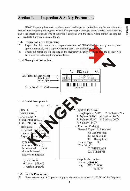
1-1-1. Name plant Instruction 1
1-1-2. Model description 2:
1-2. Safety Precautions ※ Never connect the A.C. power supply to the output terminals (U, V, W) of the frequency
PI 800 0 A 1 004 G 3
Input voltage level 1: single-phase 220V 2: 3-phase 220V 3: 3-phase 380V 4: 3-phase 460V 5: 3-phase 575V 6: 3-phase 660V 9: 3-phase 1140V
class code: 0: normal configuration 1:spetial 1 configuration 2:spetial 2 configuartion
POWER INVERTER
type code a: normal (elided) b: inhanced c: mini d: single board a1:version upgrade
Serial Name PI800: PI8000 Serial PI801: PI8100 Serial
Function Code( ) General Type F: Flow load
G: General load M: Middle load H: Heavy load
Special Type S: TEXDRIVE
T: WINDLASS Z: JETDRIVE
Applicable motor capacity( ) e.g: 7R5: 7.5KW 4: 4KW
type version 0: Lack (elided) 1:version upgrade
Section I Inspection & Safety Precaution
2
Section I
inverter. ※ Fix and lock the panel before supplying power so as to avoid the danger caused by the poor
capacity or other components inside the inverter. ※ After the power supply is switched on, do not perform wiring or check, etc. ※ Don‘t touch the circuit boards or its parts or components in the inverter when it is powered,
so as to avoid danger of electric shock. ※ If the power supply is switched off, do not touch the PCB or other parts inside the inverter
within 5 minutes after the keyboard indicator lamp goes off, and you must check by using the instrument that the inverter has completely discharged all its capacity before you start to work inside the inverter. Otherwise, there will be the danger of electric shock.
※ The static electricity in human body will cause serious damage to the MOS field effect transistor in the inverter. Please keep your hands away from the PCB, IGBT and other internal parts before taking actions to prevent static electricity. Otherwise, faults may be caused.
※ In use, the earthing terminal ( ) of the frequency inverter must be grounded to the earthing connections correctly and securely according to the national electrical safety specifications and other applicable standards.
※ Please don‘t shut off the unit by turning off the power supply. Turn off the power supply after the motor has stopped its operation.
※ Meet CE standard with EMI filter.
1-3. Application ※ Frequency inverter is generally applied to 3 phase AC asynchronism motors. ※ Frequency inverter is applied to the admissive occasion, the occasion where is not admissive
may lead to fire, electric shock, explosion and so on. ※ If the inverter seizes up when it is applied to the equipment which may lead danger (e.g. lift
tools of transportation, aviation system, saftety equipment, etc), it should be managed carefully. Do inquire the factory when it happens.
Only the well-trained personnel are allowed to use this unit, and such personnel must read through the parts of this manual relating to the safety, installation, operation and maintenance before using the unit. The safe operation of this unit depends on correct transport, installation, operation and maintenance!
3
Section II
Section II. Installation & Standby Circuit
2-1. Conditions for Use 1) Ambient temperature -10~40. 2) Avoid electromagnetic interference and keep the unit away from the interference source. 3) Prevent dropping water, steam, dust, powder, cotton fiber or fine metal powder from entering it. 4) Prevent oil, salt and corrosive gas from entering it. 5) Avoid vibration. 6) Avoid high temperature and moisture and avoid being wetted due to raining, with the humidity
below 90%RH (not dewing). 7) Prohibit the use in the dangerous environment where inflammable or combustible or explosive
gas, liquid or solid exists.
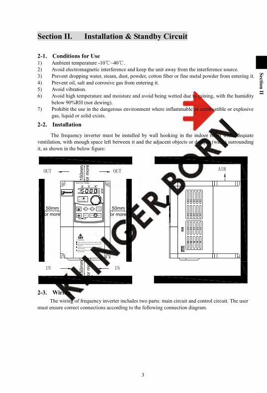
2-2. Installation
The frequency inverter must be installed by wall hooking in the indoor room with adequate ventilation, with enough space left between it and the adjacent objects or damper (walls) surrounding it, as shown in the below figure:
OUT
150m
m
50mm 50mmPRG FWDMF2MF1
ESC STOP/RESETSET
DIGITAL PANEL
+
-
+
EN
TER
ALARM
V
A
Hz
s
%°C
-
FWD REV
S00 设定频率 0.00 0.0
S01 实际频率
S10 PID反馈值
WARNINGRead the operation manual before adjust or inspect.
High voltage inside.Maintained by the well-trained personnel.
Confirm the input and output dc control cables arewell connected.Adjust or inspect the inner circuits after power down and discharge.
OUT
IN IN
150m
m
or more
AIR
or more
or m
ore
or m
ore
2-3. Wiring The wiring of frequency inverter includes two parts: main circuit and control circuit. The user
must ensure correct connections according to the following connection diagram.

Section II Intallation & Standby Circuit
4
Section II
2-3-1. PI8000 Diagram
1. Wiring diagram 11kW ~15kW and below (8N2)

Section II Inspection & Standby Circuit
5
Section II
2. Wiring diagram 18.5kW~355kW(8N3/8N4 /8N5 /8N6 /8N7 /8N8 /8N9 /8NA /8NB)
Section II Intallation & Standby Circuit
6
Section II
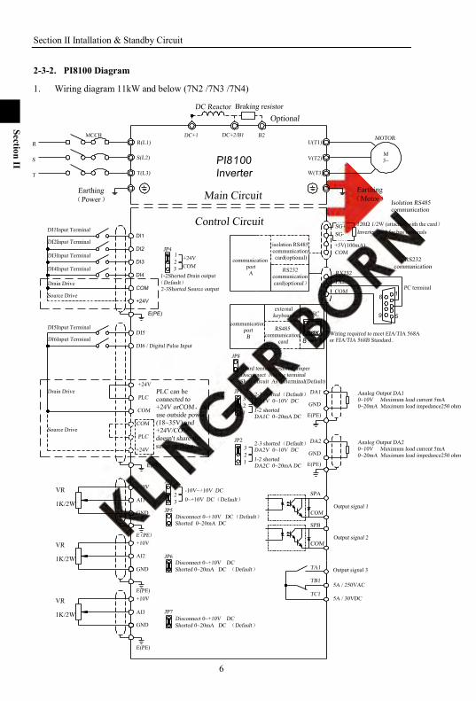
2-3-2. PI8100 Diagram
1. Wiring diagram 11kW and below (7N2 /7N3 /7N4)
Section II Inspection & Standby Circuit
7
Section II
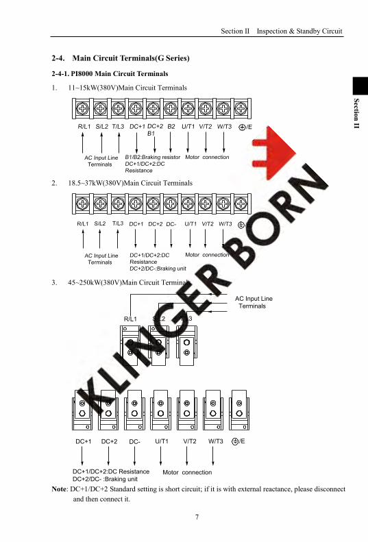
2-4. Main Circuit Terminals(G Series)
2-4-1. PI8000 Main Circuit Terminals
1. 11~15kW(380V)Main Circuit Terminals
2. 18.5~37kW(380V)Main Circuit Terminals
3. 45~250kW(380V)Main Circuit Terminals
T/L3
AC Input Line Terminals
R/L1 S/L2
Motor connection
W/T3V/T2U/T1DC+1 DC+2 DC- /E
DC+1/DC+2:DC ResistanceDC+2/DC- :Braking unit
Note: DC+1/DC+2 Standard setting is short circuit; if it is with external reactance, please disconnect and then connect it.

Section II Intallation & Standby Circuit
8
Section II
4. 280~355kW(380V)Main Circuit Terminals
2-4-2. PI8100 Main Circuit Terminals
1. 7.5kW below(380V)Main Circuit Terminals
Note: The above kW categaries are for G type inverter.
2-4-3. Terminal Function Terminal Description Functions
R/L1 Power input for frequency inverter
Connected to 3-phase power (Single input connected to R, T) S/L2
T/L3
Grounding point Grounded to the earth
B1, B2 Connection point for braking resistance
Connect brake resistance
U/T1
3 Phase Output Connected to 3-phase motor V/T2
W/T3
DC+2, DC- DC Bus output Connect the brake brake unit.
DC+1, DC+2 DC reactance connection terminal.
Connect DC reactance (No short circuit).
2-5. Control Circuit Terminals
2-5-1. Control Circuit Terminals Description Classify Terminal Description Functions
Input signal
DI1 DI1 Input Terminal Multi-functions input terminal.For details Please read o36~o46 DI2 DI2 InputTerminal
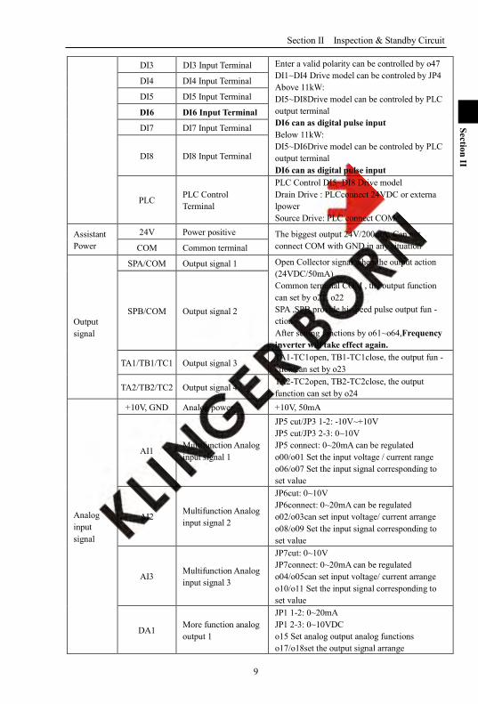
Section II Inspection & Standby Circuit
9
Section II
DI3 DI3 Input Terminal Enter a valid polarity can be controlled by o47 DI1~DI4 Drive model can be controled by JP4 Above 11kW: DI5~DI8Drive model can be controled by PLC output terminal DI6 can as digital pulse input Below 11kW: DI5~DI6Drive model can be controled by PLC output terminal DI6 can as digital pulse input
DI4 DI4 Input Terminal
DI5 DI5 Input Terminal
DI6 DI6 Input Terminal
DI7 DI7 Input Terminal
DI8 DI8 Input Terminal
PLC PLC Control Terminal
PLC Control DI5~DI8 Drive model Drain Drive : PLCconnect 24VDC or externa lpower Source Drive: PLC connect COM
Assistant Power
24V Power positive The biggest output 24V/200mA, Can not connect COM with GND in any situation COM Common terminal
Output signal
SPA/COM Output signal 1 Open Collector signal when the output action (24VDC/50mA) Common terminal COM , the output function can set by o21, o22 SPA ,SPB provide hi-speed pulse output fun - ction. After setting functions by o61~o64,Frequency inverter will take effect again.
SPB/COM Output signal 2
TA1/TB1/TC1 Output signal 3 TA1-TC1open, TB1-TC1close, the output fun - ction can set by o23
TA2/TB2/TC2 Output signal 4 TA2-TC2open, TB2-TC2close, the output function can set by o24
Analog input signal
+10V, GND Analog power +10V, 50mA
AI1 Multifunction Analog input signal 1
JP5 cut/JP3 1-2: -10V~+10V JP5 cut/JP3 2-3: 0~10V JP5 connect: 0~20mA can be regulated o00/o01 Set the input voltage / current range o06/o07 Set the input signal corresponding to set value
AI2 Multifunction Analog input signal 2
JP6cut: 0~10V JP6connect: 0~20mA can be regulated o02/o03can set input voltage/ current arrange o08/o09 Set the input signal corresponding to set value
AI3 Multifunction Analog input signal 3
JP7cut: 0~10V JP7connect: 0~20mA can be regulated o04/o05can set input voltage/ current arrange o10/o11 Set the input signal corresponding to set value
DA1 More function analog output 1
JP1 1-2: 0~20mA JP1 2-3: 0~10VDC o15 Set analog output analog functions o17/o18set the output signal arrange

Section II Intallation & Standby Circuit
10
Section II
DA2 More function analog output 2
JP2 1-2: 0~20mA JP2 2-3: 0~10VDC o16 Set analog output analog functions o19/o20 set the output signal arrange
2-5-2. Control circuit terminal
1. 8KLCB Control circuit terminal
2. 8KSCB Control circuit terminal
2-6. Connection Precautions ※ Don‘t install power factor capacitance or resistance-capacitance absorbing device between
the output terminals U, V, W of the frequency inverter.
※ To disassemble or replace the motor, the input power supply must be turned off for the frequency inverter.
※ Do not drop Metal scrap foam or lint into the frequency inverter, otherwise the machine will be faulted.
※ The motor or power supply can be switched on/off only after the inverter stops its output.
※ In order to minimize the effect of electromagnetic interference, a surge absorbing device should be installed if used electromagnetic contactor and relay, etc. is near to the frequency inverter.
※ For external control of frequency inverter, a isolation device should be used for the control lines or screened cable should be used.
※ A screened cable should be used as the signal connection line for input command and must be routed separately as well, and it is better be installed far from the main circuit.
※ When the carrier frequency is less than 3kHz, the distance between the frequency inverter and motor must not be greater than 50 meters (maximum). When it is above 4kHz, this distance should be reduced. The cable for this connection had better be laid in metal conduit.
※ If the frequency inverter is equipped with peripheral devices (such as filter, reactor), first measure its insulation resistance to the earth with 1000V megohm meter, and ensure the resistance value is not below 4MΩ.
Section II Inspection & Standby Circuit
11
Section II
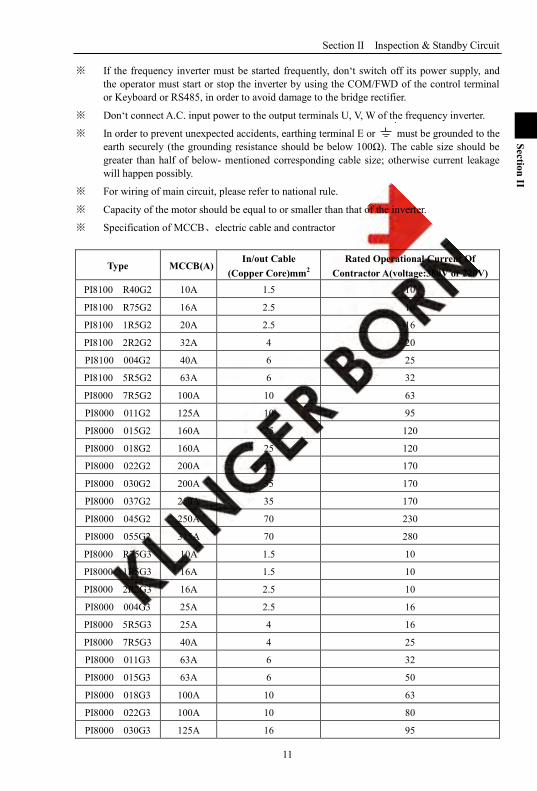
※ If the frequency inverter must be started frequently, don‘t switch off its power supply, and the operator must start or stop the inverter by using the COM/FWD of the control terminal or Keyboard or RS485, in order to avoid damage to the bridge rectifier.
※ Don‘t connect A.C. input power to the output terminals U, V, W of the frequency inverter.
※ In order to prevent unexpected accidents, earthing terminal E or must be grounded to the earth securely (the grounding resistance should be below 100Ω). The cable size should be greater than half of below- mentioned corresponding cable size; otherwise current leakage will happen possibly.
※ For wiring of main circuit, please refer to national rule.
※ Capacity of the motor should be equal to or smaller than that of the inverter.
※ Specification of MCCB、electric cable and contractor
Type MCCB(A) In/out Cable
(Copper Core)mm2 Rated Operational Current Of
Contractor A(voltage:380V or 220V) PI8100 R40G2 10A 1.5 10
PI8100 R75G2 16A 2.5 10
PI8100 1R5G2 20A 2.5 16
PI8100 2R2G2 32A 4 20
PI8100 004G2 40A 6 25
PI8100 5R5G2 63A 6 32
PI8000 7R5G2 100A 10 63
PI8000 011G2 125A 10 95
PI8000 015G2 160A 25 120
PI8000 018G2 160A 25 120
PI8000 022G2 200A 25 170
PI8000 030G2 200A 35 170
PI8000 037G2 250A 35 170
PI8000 045G2 250A 70 230
PI8000 055G2 315A 70 280
PI8000 R75G3 10A 1.5 10
PI8000 1R5G3 16A 1.5 10
PI8000 2R2G3 16A 2.5 10
PI8000 004G3 25A 2.5 16
PI8000 5R5G3 25A 4 16
PI8000 7R5G3 40A 4 25
PI8000 011G3 63A 6 32
PI8000 015G3 63A 6 50
PI8000 018G3 100A 10 63
PI8000 022G3 100A 10 80
PI8000 030G3 125A 16 95

Section II Intallation & Standby Circuit
12
Section II
PI8000 037G3 160A 25 120
PI8000 045G3 200A 35 135
PI8000 055G3 250A 35 170
PI8000 075G3 315A 70 230
PI8000 093G3 400A 70 280
PI8000 110G3 400A 95 315
PI8000 132G3 400A 95 380
PI8000 160G3 630A 150 450
PI8000 187G3 630A 185 500
PI8000 200G3 630A 240 580
PI8000 220G3 800A 150*2 630
PI8000 250G3 800A 150*2 700
PI8000 280G3 1000A 185*2 780
PI8000 315G3 1200A 240*2 900
PI8000 355G3 1280A 240*2 960
PI8000 400G3 1380A 185*3 1035
PI8000 500G3 1720A 185*3 1290
2-7. Standby circuit When the fault or trip of the inverter may cause great loss or accident, please add the standby circuit.
Note:confirm and test the running characteristic of the standby circuit, in order to ensure the industrial phase and the converter phase are in the same direction.
T
RS
Inverter
R
Interlock relay
PI80003-PHASEAC POWER SUPPLY
M 3~T
SUVW
MCC1
MCC2
13
Section III
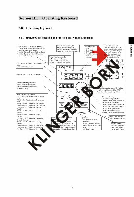
Section III. Operating Keyboard
2-8. Operating keyboard
3-1-1. JP6E8000 specification and function description(Standard)
+
-
DIGITAL PANEL
FWD REV ALARM
+
-
Hz
A
V
%
s
ENTER
PRG
ESC
MF1 MF2 FWD
SET STOP/RESET
Reset /Stop Key* drive stop running* Exception Reset* fault confirmation
Forward running key* drive forward running
Forward Indication Light* ON:forward indication* OFF:not forward indication* FLASH:forward accelerating
Alarm Indication Light
* ON:faulty* OFF:good* FLASH:previous
fault was not confirmed
Acceleration Select/Parameter Setting Key
* press SET key and rotate JOG key while selecting parameter, the parameter location changes to 10
* finish and save the value changes* change the object under monitor
Quit Key* exit the revisement of
parameter* reture to displaying menu
from submenu or functional menu
* exit default state
Positive And Negative Sign Indication Light* just for monitor select
Parameter Setting/Shift Key* start to change parameter* Functions value adjustments Modification bit
Multi-function Key MF1/MF2* MF1 define functions through parameter A43 * MF2 define functions through parameter A44* A43/A44=0 MF defined as plus function* A43/A44=1 MF defined as minus function* A43/A44=2 MF defined as free stop function* A43/A44=3 MF defined as forward function* A43/A44=4 MF defined as reverse function* A43/A44=5 MF defined as Punctuality dynamic function* A43/A44=6 MF defined as Anti-Jog function* A43/A44=7 MF defined as Jog function* A43/A44=8 MF defined as Up function* A43/A44=9 MF defined as Down function
ENTER* have the same function with PRG/ ,
refer to explaination of key PRG/* Invalid in the monitoring state
Monitor Select 1 Numerical Display* display the corresponding values of the
function under query status* display fault code under fault condition* display the object set byA00 monitor
select while running
Potentiometer Key* under checking state, the
function items value has been in increment or decrement
* under revising state, the edit bit of function items value has been in increment or decrement
* under monitoring, setting frequency to increase or decrease
Reverse Indication Light* ON:reverse indication* OFF:not reverse indication* FLASH:reverse accelerating
Data Unit Prompt Light*composed of three indication lights,located on the right side of the LED digital tube,Display status corresponding to the six units,indicate the unit of the parameters displayed by LED。*the correspondence is as following:
OFF
ON
°CS%
VAHz
S
V
%
A °C
Hz
UNITUNITHz
°CA
%
V
S
S
V
%
A °C
Hz
UNIT
UNITHz
°CA
%
V
S
S
V
%
A °C
Hz
UNITUNITHz
°CA
%
V
S
NO UNITS
S
V
%
A °C
Hz
UNIT
Monitor Select 2 Numerical Display
Section III Operating Keyboard
14
Section III
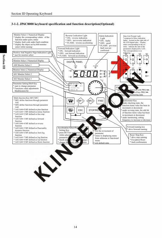
3-1-2. JP6C8000 keyboard specification and function description(Optional)
Data Unit Prompt Light*composed of three indication lights,located on the right side of the LED digital tube,Display status corresponding to the six units,indicate the unit of the parameters displayed by LED。*the correspondence is as following:
OFF
ON
°CS%
VAHz
S
V
%
A °C
Hz
UNITUNITHz
°CA
%
V
S
S
V
%
A °C
Hz
UNIT
UNITHz
°CA
%
V
S
S
V
%
A °C
Hz
UNITUNITHz
°CA
%
V
S
NO UNITS
S
V
%
A °C
Hz
UNIT
A00 Monitor Select 1
Monitor Select 3 Numerical Display
Monitor Select 2 Numerical Display
A01 Monitor Select 2
A02 Monitor Select 3
Forward Indication Light* ON:forward indication* OFF:not forward indication* FLASH:forward accelerating
Positive And Negative Sign Indication Light* just for monitor select
Parameter Setting/Shift Key* start to change parameter* Functions value adjustments
Modification bit
Multi-function Key MF1/MF2* MF1 define functions through parameter
A43 * MF2 define functions through parameter
A44* A43/A44=0 MF defined as plus function* A43/A44=1 MF defined as minus function* A43/A44=2 MF defined as free stop
function* A43/A44=3 MF defined as forward
function* A43/A44=4 MF defined as reverse
function* A43/A44=5 MF defined as Punctuality
dynamic function* A43/A44=6 MF defined as Anti-Jog
function* A43/A44=7 MF defined as Jog function* A43/A44=8 MF defined as Up function* A43/A44=9 MF defined as Down function
Acceleration Select/Parameter Setting Key
* press SET key and rotate JOG key while selecting parameter, the parameter location changes to 10
* finish and save the value changes* change the object under monitor
Reset /Stop Key* drive stop running* Exception Reset* fault confirmation
Forward running key* drive forward running
ENTER* have the same function with PRG/ ,
refer to explaination of key PRG/* Invalid in the monitoring state
Monitor Select 1 Numerical Display* display the corresponding values of the
function under query status* display fault code under fault condition* display the object set byA00 monitor
select while running
Alarm Indication Light
* ON:faulty* OFF:good* FLASH:previous
fault was not confirmed
Quit Key* exit the revisement of
parameter* reture to displaying menu
from submenu or functional menu
* exit default state
Potentiometer Key* under checking state, the
function items value has been in increment or decrement
* under revising state, the edit bit of function items value has been in increment or decrement
* under monitoring, setting frequency to increase or decrease
Reverse Lndication Light* ON:reverse indication* OFF:not reverse indication* FLASH:reverse accelerating
DIGITAL PANEL
FWD REV ALARM
+
-
Hz
A
V
%
s
ENTER
PRG
ESC
MF1 MF2 FWD
SET STOP/RESET
S00 Set Fre.0.00
1 Actual Fre.
2 Motor AC
0.5
+
-
Section III Operating Keyboard
15
Section III
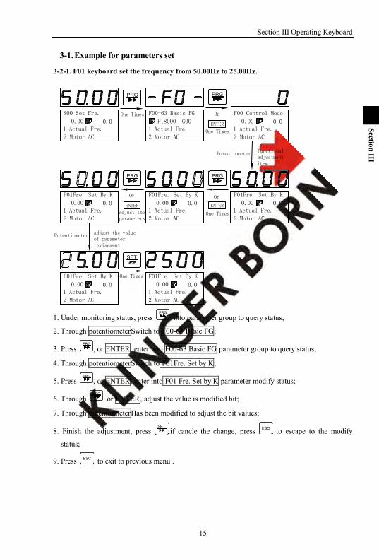
3-1. Example for parameters set
3-2-1. F01 keyboard set the frequency from 50.00Hz to 25.00Hz.
One Times
adjust the value of parameter revisement
Potentiometer
One Times
Or
One Times
Potentiometer
One Times
S00 Set Fre.
0.001 Actual Fre.
2 Motor AC
0.0
F00-63 Basic FG
PI8000 G00
PRG PRG
Or
ENTER
F00 Control Mode
0.00 0.0
0.00 0.00.00 0.0
PRG
ENTER
PRG
adjust the parameters
Or
ENTER
F01Fre. Set By K
0.00 0.0
SET
0.00 0.0 0.00 0.0
Functional adjustment item
1 Actual Fre.
2 Motor AC
1 Actual Fre.
2 Motor AC
1 Actual Fre.
2 Motor AC
1 Actual Fre.
2 Motor AC
1 Actual Fre.
2 Motor AC
1 Actual Fre.
2 Motor AC
1 Actual Fre.
2 Motor AC
F01Fre. Set By K F01Fre. Set By K
F01Fre. Set By K F01Fre. Set By K
1. Under monitoring status, press PRG
into parameter group to query status;
2. Through potentiometerSwitch to F00-63 Basic FG;
3. Press PRG
, or ENTER, enter into F00-63 Basic FG parameter group to query status;
4. Through potentiometerSwitch to F01Fre. Set by K;
5. Press PRG
, or ENTER, enter into F01 Fre. Set by K parameter modify status;
6. Through PRG
, or ENTER, adjust the value is modified bit;
7. Through potentiometerHas been modified to adjust the bit values;
8. Finish the adjustment, press SET
;if cancle the change, press ESC to escape to the modify
status;
9. Press ESC to exit to previous menu .
Section III Operating Keyboard
16
Section III
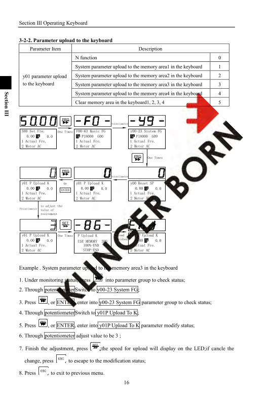
3-2-2. Parameter upload to the keyboard Parameter Item Description
y01 parameter upload to the keyboard
N function 0
System parameter upload to the memory area1 in the keyboard 1
System parameter upload to the memory area2 in the keyboard 2
System parameter upload to the memory area3 in the keyboard 3
System parameter upload to the memory area4 in the keyboard 4
Clear memory area in the keyboard1, 2, 3, 4 5
y01 P Upload K y00 Reset SP
y01 P Upload K P Upload K y01 P Upload K
to adjust the value of resivement
One Times
One Times
One Times
Potentiometer
Potentiometer
Potentiometer
0.00 0.0 PI8000 G00
PRG
0.00 0.00.00 0.0
PRG
Or
ENTER
SET
USE MEMORY 3RD100%-ENDSTOP-END
y00-23 System FG
PI8000 G09
PRG
y01 P Upload K
0.00 0.0
0.00 0.0 0.00 0.0
UploadFinished
1 Actual Fre.
2 Motor AC
1 Actual Fre.
2 Motor AC
1 Actual Fre.
2 Motor AC
1 Actual Fre.
2 Motor AC
1 Actual Fre.
2 Motor AC
1 Actual Fre.
2 Motor AC
1 Actual Fre.
2 Motor AC
1 Actual Fre.
2 Motor AC
S00 Set Fre. F00-63 Basic FG
Example . System parameter upload to the memory area3 in the keyboard
1. Under monitoring status, press PRG
into parameter group to check status;
2. Through potentiometerSwitch to y00-23 System FG;
3. Press PRG
, or ENTER, enter into y00-23 System FG parameter group to check status;
4. Through potentiometerSwitch to y01P Upload To K;
5. Press PRG
, or ENTER, enter into y01P Upload To K parameter modify status;
6. Through potentiometer adjust value to be 3 ;
7. Finish the adjustment, press SET
;the speed for upload will display on the LED;if cancle the
change, press ESC to escape to the modification status;
8. Press ESC to exit to previous menu.

Section III Operating Keyboard
17
Section III
3-2-3. Reset system parameters Parameter Item Description
y00 Reset system parameters
N function 0
memory area1 in the keyboard to reset system parameter 1
memory area2 in the keyboard to reset system parameter 2
memory area3 in the keyboard to reset system parameter 3
memory area4 in the keyboard 1to reset system parameter 4
Use the factory setting reset system parameter 5
PRG
One Times
y00-23 System FG
y00 Reset SPy00 Reset SPto adjust the value of resivement
One Times
One Times
One Times
Potentiometer
Potentiometer
y00 Reset SP
0.00 0.01 Actual Fre.
2 Motor AC
0.00 0.0 PI8000 G00
PRG
0.00 0.0
SET
P Donload K
USE MEMORY 3RD100%-ENDSTOP-END
PI8000 G09
PRG
y00 Reset SP
0.00 0.00.00 0.0
DownloadFinished
1 Actual Fre.
2 Motor AC
1 Actual Fre.
2 Motor AC
1 Actual Fre.
2 Motor AC
1 Actual Fre.
2 Motor AC
1 Actual Fre.
2 Motor AC
1 Actual Fre.
2 Motor AC
S00 Set Fre. F00-63 Basic FG
Example 1: memory area3 in the keyboard 1 to reset system parameter
1. Under monitoring status, press PRG
into parameter group to query status
2. Through potentiometerSwitch to y00-23 System FG;
3. Press PRG
, or ENTER, enter into y00-23 System FG parameter group to query status;
4. Through potentiometerSwitch to y01P Upload To K;
5. Press PRG
, or ENTER, enter into y00 Reset SP parameter modify status;
6. Through potentiometer adjust to 3 ;
7. Finish the adjustment, press SET
;the speed for download will display on the LED;if cancle the
change, press ESC ;
8. Press ESC to exit to previous menu.

Section III Operating Keyboard
18
Section III
Example 2 Clear memory area 1, 2, 3, 4 in the keyboard
0.00 0.0 PI8000 G00
PRG
0.00 0.00.00 0.0
PRG
ENTER
SET
PI8000 G09
PRG
0.00 0.0
0.00 0.0 0.00 0.0
Clearance
Finished0.00 0.0
1 Actual Fre.
2 Motor AC
1 Actual Fre.
2 Motor AC
1 Actual Fre.
2 Motor AC
1 Actual Fre.
2 Motor AC
1 Actual Fre.
2 Motor AC
1 Actual Fre.
2 Motor AC
1 Actual Fre.
2 Motor AC
1 Actual Fre.
2 Motor AC
1 Actual Fre.
2 Motor AC
S00 Set Fre. F00-63 Basic FG y00-23 System FG
y00 Reset SP
adjust the value of parameter revisement
Potentiometer
One Times
One Times
One Times
Ory01P Upload To K y01P Upload To K
y01P Upload To K y01P Upload To K y01P Upload To K
Potentiometer
Potentiometer
1. Under monitoring status, press PRG
into parameter group to check status
2. Through potentiometerSwitch to y00-23 System FG;
3. Press PRG
, or ENTER, enter into y00-23 System FG parameter group to check status;
4. Through potentiometerSwitch to y01P Upload To K;
5. Press PRG
, or ENTER, enter into y01P Upload To K parameter modify status;
6. Through potentiometer adjust to 5 ;
7. Finish the adjustment, press SET
;the speed for Clear memory area will display on the LED;if
cancle the change, press ESC ;
8. Press ESC to exit to previous menu.
3-2-4. F02 the main set mode of set frequency is set to 4, keyboard potentiometer setting ! 1. Under monitoring status, Through potentiometer adjust the frequency, the resolution ratio
potentiometer is 0.05Hz. 2. Range of set frequency can be set with the following parameters:
Parameter item Description
F12 max. frequency Inverter output maximum frequency allowed Setting range: 10.00~320.00Hz
Section III Operating Keyboard
19
Section III
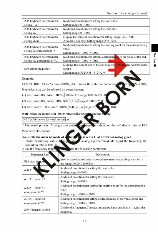
A45 keyboard potentiometer setting X1
Keyboard potentiometer setting the start value Setting range: 0~100%
A46 keyboard potentiometer setting X2
Keyboard potentiometer setting the end value Setting range: 0~100%
A47 keyboard potentiometer setting value
Display the value of potentiometer setting, range: A45~A46 Also can set diretly, Setting range: A45~A46
A48 keyboard potentiometer setting X1correspond to Y1
Keyboard potentiometer setting the starting point for the corresponding value Setting range: -100%~+100%
A49 keyboard potentiometer setting X2 correspond to Y2
Keyboard potentiometer settings corresponding to the value of the end Setting range: -100%~+100%
S00 setting frequency Displays the current size of the set frequency,through the potentiometer setting Setting range: F12*A48~ F12*A49
Example:
F12=50.00Hz, A45=0%, A46=100%, A47 Shows the value of potentiometer settings 0%~100%,
Numerical size can be adjusted by potentiometer.
(1) when A48=0%, A49=+100%, S00 Set Fre.range 0.00Hz~50.00Hz.
(2) when A48=0%, A49=+50%, S00 Set Fre.range 0.00Hz~25.00Hz.
(3) when A48=-100%, A49=+100%, S00 Set Fre.range -50.00Hz~50.00Hz.
Note: when the motor is in -50.00~0Hz realise reverse, another setting
F45 Ten bit motor forward inverse as
1 Command priority: Analog given positive and negative values, on the F45 details refer to F45
Parameter Description
3-2-5. F02 the main set mode of set frequency is set to 1, AI1 external analog given. 1. Under monitoring status, Through external analog input terminal Al1 adjust the frequency, the
resolution ratio is 0.01Hz. 2. Set the frequency range can be set with the following parameters:
Parameter Item Description
F12 most frequency Inverter speed adjustment‘s allowed maximum output frequency Sett - ing range: 10.00~320.00Hz
o00 AI1 input X1 Keyboard potentiometer setting the start value Setting range: 0~100%
o01 AI1 input X2 Keyboard potentiometer setting the end value Setting range: 0~100%
o06 AI1 input X1 correspond to Y1
Keyboard potentiometer setting the starting point for the corresponding value Setting range: -100%~+100%
o07 AI1 input X2 correspond to Y2
Keyboard potentiometer settings corresponding to the value of the end Setting range: -100%~+100%
S00 frequency setting Display the frequency,Through out analog input terminal Al1 adjust the frequency

Section III Operating Keyboard
20
Section III
Setting range: F12*o06~ F12*o07
Example:
F12=50.00Hz, o00=0%, o01=100%,
(1) When o06=0%, o07=+100%, S00 Set Fre.range 0.00Hz~50.00Hz.
(2) When o06=0%, o07=+50%, S00 Set Fre.range 0.00Hz~25.00Hz.
(3) When o06=-100%, o07=+100%, S00 Set Fre.range -50.00Hz~50.00Hz.
Note: When realize the motor reverse in -50.00~0Hz。
F45Ten bit motor forward reverse as
1 Command priority: Analog given positive and negative values, on the F45 details see F45
Parameter Description
21
Section IV
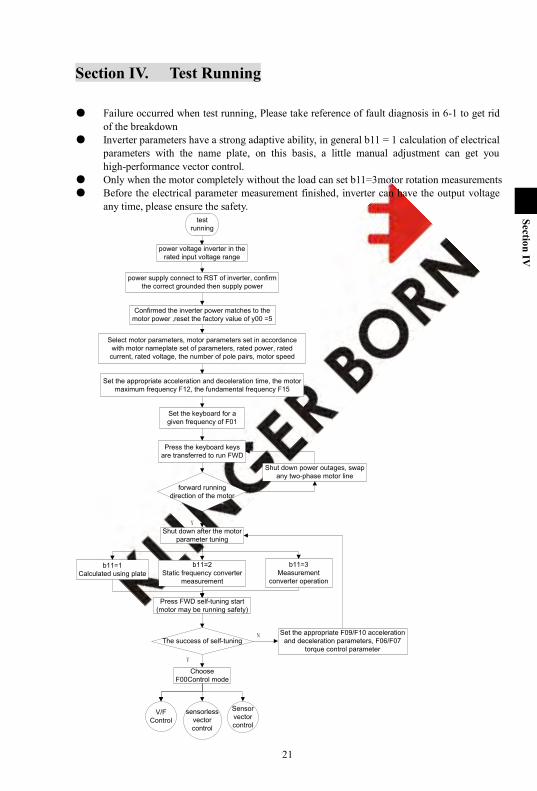
Section IV. Test Running
Failure occurred when test running, Please take reference of fault diagnosis in 6-1 to get rid of the breakdown
Inverter parameters have a strong adaptive ability, in general b11 = 1 calculation of electrical parameters with the name plate, on this basis, a little manual adjustment can get you high-performance vector control.
Only when the motor completely without the load can set b11=3motor rotation measurements Before the electrical parameter measurement finished, inverter can have the output voltage
any time, please ensure the safety. test
running
power voltage inverter in the rated input voltage range
power supply connect to RST of inverter, confirm the correct grounded then supply power
Confirmed the inverter power matches to the motor power ,reset the factory value of y00 =5
Select motor parameters, motor parameters set in accordance with motor nameplate set of parameters, rated power, rated
current, rated voltage, the number of pole pairs, motor speed
Set the appropriate acceleration and deceleration time, the motor maximum frequency F12, the fundamental frequency F15
Set the keyboard for a given frequency of F01
Press the keyboard keys are transferred to run FWD
Shut down power outages, swap any two-phase motor line
Shut down after the motor parameter tuning
b11=3Measurement
converter operation
b11=2Static frequency converter
measurement
b11=1Calculated using plate
Press FWD self-tuning start (motor may be running safety)
forward running direction of the motor
V/F Control
sensorless vector control
Sensor vector control
The success of self-tuning
Choose F00Control mode
Set the appropriate F09/F10 acceleration and deceleration parameters, F06/F07
torque control parameterY
N
Y
N

Section IV Test Runing
22
Section IV
According to parameter setting F06 V / F boost
mode
Set F07 torque boost value
setting F01 running frequency
running
observe running current and motor state
parameters optimization
Normal operation
Stop and test running finish
upper torque setting
running
Observe the motor current, excitation component, torque
fluctuation component
Stop and test running finish
Upper torque setting C13、C14
Set PG pulses C28,PG directions C30
running
Observe motor speed S06
Observe the motor current, excitation component, torque
fluctuation component
Stop and test running finish
Y
N
Y
N
Y
N
Y
N
V/FControl
sensorless vector control
sensor vector control
Normal operation
Normal operation
Normal operation
adjust speed loopC01-C07、Turned around differential gain C09-C12、regulate
motor parameters
parameters optimization
adjust speed loopC01-C07、Turned around differential gain、
regulate motor parameters
parameters optimization
23
Section V
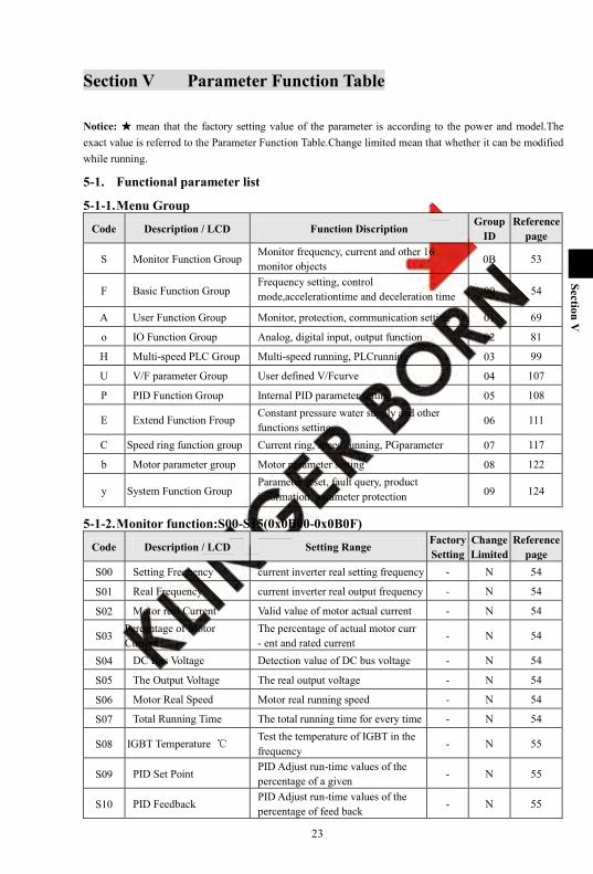
Section V Parameter Function Table
Notice: mean that the factory setting value of the parameter is according to the power and model.The exact value is referred to the Parameter Function Table.Change limited mean that whether it can be modified while running.
5-1. Functional parameter list
5-1-1. Menu Group
Code Description / LCD Function Discription Group
ID Reference
page
S Monitor Function Group Monitor frequency, current and other 16 monitor objects 0B 53
F Basic Function Group Frequency setting, control mode,accelerationtime and deceleration time 00 54
A User Function Group Monitor, protection, communication setting 01 69
o IO Function Group Analog, digital input, output function 02 81
H Multi-speed PLC Group Multi-speed running, PLCrunning 03 99
U V/F parameter Group User defined V/Fcurve 04 107
P PID Function Group Internal PID parameter setting 05 108
E Extend Function Froup Constant pressure water supply and other functions setting 06 111
C Speed ring function group Current ring, speed running, PGparameter 07 117
b Motor parameter group Motor parameter setting 08 122
y System Function Group Parameter reset, fault query, product information, parameter protection 09 124
5-1-2. Monitor function:S00-S15(0x0B00-0x0B0F)
Code Description / LCD Setting Range Factory Setting
Change Limited
Reference page
S00 Setting Frequency current inverter real setting frequency - N 54
S01 Real Frequency current inverter real output frequency - N 54
S02 Motor real Current Valid value of motor actual current - N 54
S03 Percentage of Motor Current
The percentage of actual motor curr - ent and rated current
- N 54
S04 DC Bus Voltage Detection value of DC bus voltage - N 54
S05 The Output Voltage The real output voltage - N 54
S06 Motor Real Speed Motor real running speed - N 54
S07 Total Running Time The total running time for every time - N 54
S08 IGBT Temperature Test the temperature of IGBT in the frequency
- N 55
S09 PID Set Point PID Adjust run-time values of the percentage of a given - N 55
S10 PID Feedback PID Adjust run-time values of the percentage of feed back - N 55
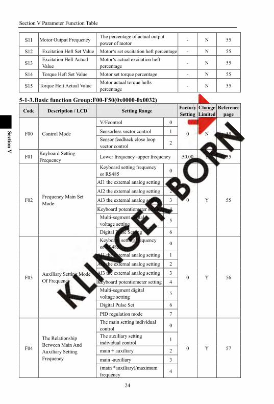
Section V Parameter Function Table
24
Section V
S11 Motor Output Frequency The percentage of actual output power of motor
- N 55
S12 Excitation Heft Set Value Motor‘s set excitation heft percentage - N 55
S13 Excitation Heft Actual Value
Motor‘s actual excitation heft percentage - N 55
S14 Torque Heft Set Value Motor set torque percentage - N 55
S15 Torque Heft Actual Value Motor actual torque hefts percentage
- N 55
5-1-3. Basic function Group:F00-F50(0x0000-0x0032)
Code Description / LCD Setting Range Factory Setting
Change Limited
Reference page
F00 Control Mode
V/Fcontrol 0
0 N 55 Sensorless vector control 1 Sensor feedback close loop vector control
2
F01 Keyboard Setting Frequency Lower frequency~upper frequency 50.00 Y 55
F02 Frequency Main Set Mode
Keyboard setting frequency or RS485 0
0 Y 55
AI1 the external analog setting 1
AI2 the external analog setting 2
AI3 the external analog setting 3
Keyboard potentiometer setting 4 Multi-segment digital voltage setting
5
Digital Pulse Setting 6
F03 Auxiliary Setting Mode Of Frequency
Keyboard setting frequency or RS485
0
0 Y 56
AI1 the external analog setting 1
AI2 the external analog setting 2
AI3 the external analog setting 3
Keyboard potentiometer setting 4 Multi-segment digital voltage setting
5
Digital Pulse Set 6
PID regulation mode 7
F04
The Relationship Between Main And Auxiliary Setting Frequency
The main setting individual control 0
0 Y 57
The auxiliary setting individual control
1
main + auxiliary 2
main -auxiliary 3 (main *auxiliary)/maximum frequency
4
Section V Parameter Function Table
25
Section V
Code Description / LCD Setting Range Factory Setting
Change Limited
Reference page
Maximum{main, auxiliary} 5
Minimum{main, auxiliary} 6
F05 Running Control Mode
Keyboard+Rs485/CAN 0
0 Y 58
Keyboard+terminal+Rs485/CAN 1
Rs485/CAN 2
Terminal control 3
The proportion linkage control 4
F06 V/F Boost Mode
1 bit
Beeline V/Fcurve 0
0000 N 59
Power of 1.2 V/Fcurve 1 Power of 1.7 power V/Fcurve
2
Power of 2 powerV/Fcurve 3
Define mode V/Fcurve 4
10 bit Close Automatic torque boost 0
Automatic orqueboost 1
100 bit VF mode 0 Speed No Output
0
VF mode keep 0 speed 1
F07 Torque boost Value 0.0~30.0% 0.0 Y 59
F08 Torque Boost Cut-off Frequency 0.00~Maximum frequency 15.00 Y 59
F09 Accelerate Time 0.0~3200.0 10.0 Y 60
F10 Decelerate Time 0.0~3200.0 10.0 Y 60
F11 Percentage Of Output Voltage
50~110 100 Y 60
F12 Maximum Frequency 10.00~320.00 50.00 N 60
F13 Lower Frequency 0.00~Upper frequency 0.00 N 60
F14 Upper Frequency Lower frequency~Upper frequency 50.00 N 60
F15 Basic Frequency 5.00~Maximum frequency 50.00 N 61
F16 Carrier Frequency 1.0~16.0 Y 61
F17 Carrier Frequency Adjustment Range
0.0~4.0 0.0 Y 62
F18 Carrier Frequency Adjustment Mode
1 bit No automatic adjustment 0
00 Y 62
automatic adjustment Mode
1
10 bit
automatic adjustment, Fixed mode
0
automatic adjustment, random mode
1
F19 Waveform Generation Asynchronous space-vector 0 0 N 62
Section V Parameter Function Table
26
Section V
Code Description / LCD Setting Range Factory Setting
Change Limited
Reference page
Mode PWM
Stepless & subsection synchronous space vector PWM
1
two-phase optimization space vector PWM
2
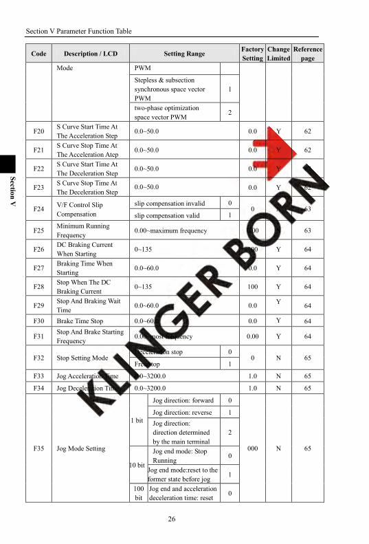
F20 S Curve Start Time At The Acceleration Step 0.0~50.0 0.0 Y 62
F21 S Curve Stop Time At The Acceleration Atep 0.0~50.0 0.0 Y 62
F22 S Curve Start Time At The Deceleration Step
0.0~50.0 0.0 Y 62
F23 S Curve Stop Time At The Deceleration Step
0.0~50.0 0.0 Y 62
F24 V/F Control Slip Compensation
slip compensation invalid 0 0 N 63
slip compensation valid 1
F25 Minimum Running Frequency
0.00~maximum frequency 0.00 N 63
F26 DC Braking Current When Starting 0~135 100 Y 64
F27 Braking Time When Starting 0.0~60.0 0.0 Y 64
F28 Stop When The DC Braking Current
0~135 100 Y 64
F29 Stop And Braking Wait Time
0.0~60.0 0.0 Y 64
F30 Brake Time Stop 0.0~60.0 0.0 Y 64
F31 Stop And Brake Starting Frequency
0.00~most frequency 0.00 Y 64
F32 Stop Setting Mode Deceleration stop 0
0 N 65 Free stop 1
F33 Jog Acceleration Time 0.0~3200.0 1.0 N 65
F34 Jog Deceleration Time 0.0~3200.0 1.0 N 65
F35 Jog Mode Setting
1 bit
Jog direction: forward 0
000 N 65
Jog direction: reverse 1 Jog direction: direction determined by the main terminal
2
10 bit
Jog end mode: Stop Running
0
Jog end mode:reset to the former state before jog 1
100 bit
Jog end and acceleration deceleration time: reset 0

Section V Parameter Function Table
27
Section V
Code Description / LCD Setting Range Factory Setting
Change Limited
Reference page
to the set acceleration and deceleration time before jog Jog end and acceleration deceleration time:save the set acceleration and deceleration time before jog
1
F36 Jog Frequency Setting Lower frequency ~upper frequency 6.00 Y 66
F37 Skip Frequency1Limit 0.00~Maximum frequency 0.00 Y 66
F38 Skip Frequency1Upper 0.00~Maximum frequency 0.00 Y 66
F39 Skip Frequency2Limit 0.00~Maximum frequency 0.00 Y 66
F40 Skip Frequency2Upper 0.00~Maximum frequency 0.00 Y 66
F41 Skip Frequency3Limit 0.00~Maximum frequency 0.00 Y 66
F42 Skip Frequency3Upper 0.00~Maximum frequency 0.00 Y 66
F43 Preset Frequency 0.00~Max frequency 0.00 Y 67
F44 Preset Frequency Working Time 0.0~60.0 0.0 Y 67
F45 Motor Running Direction
1 bit
Direction command: forward command FWD let motor forward running
0
0100 N 67
Direction command: forward command FWD let motor reverse running
1
10 bit
Command prior: terminal/keyboard
0
Prior command: Analog given positive and negative values
1
100 bit
Reverse allow: reverse forbidden
0
Reverse allow: reverse allow
1
F46 Pass 0 Stopping Time 0.0~60.0s 0 N 67
F47 Frequency Multiple Setting
*1 0 0 N 68
*10 1
F48 Acceleration And Deceleration Configuration Word
1 bit
N adjustment of acceleration time
0
0000 N 68 AI1 adjustment of the external analog giving
1
AI2 adjustment of the external analog giving
2
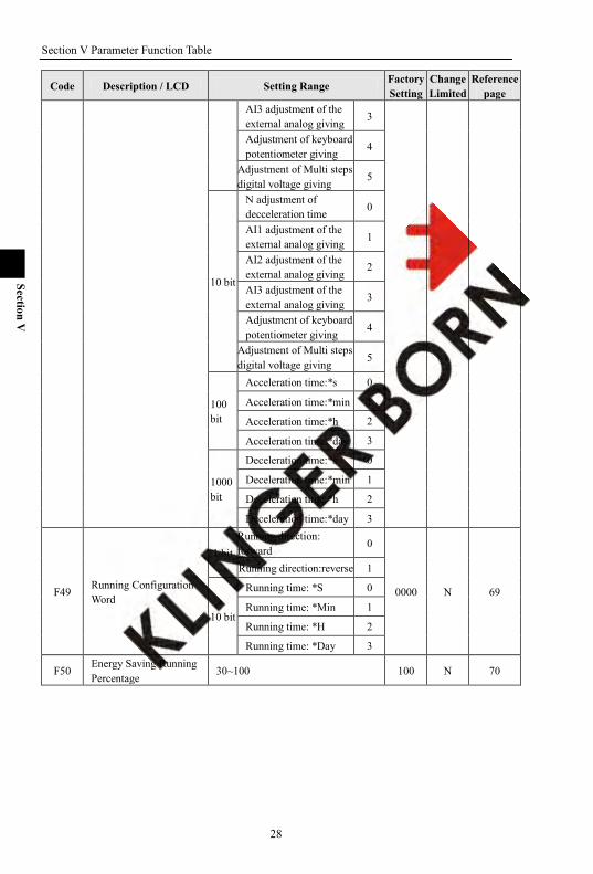
Section V Parameter Function Table
28
Section V
Code Description / LCD Setting Range Factory Setting
Change Limited
Reference page
AI3 adjustment of the external analog giving
3
Adjustment of keyboard potentiometer giving
4
Adjustment of Multi steps digital voltage giving
5
10 bit
N adjustment of decceleration time 0
AI1 adjustment of the external analog giving 1
AI2 adjustment of the external analog giving
2
AI3 adjustment of the external analog giving
3
Adjustment of keyboard potentiometer giving
4
Adjustment of Multi steps digital voltage giving
5
100 bit
Acceleration time:*s 0
Acceleration time:*min 1
Acceleration time:*h 2
Acceleration time:*day 3
1000 bit
Deceleration time:*s 0
Deceleration time:*min 1
Deceleration time:*h 2
Deceleration time:*day 3
F49 Running Configuration Word
1 bit Running direction: forward
0
0000 N 69
Running direction:reverse 1
10 bit
Running time: *S 0
Running time: *Min 1
Running time: *H 2
Running time: *Day 3
F50 Energy Saving Running Percentage
30~100 100 N 70
Section V Parameter Function Table
29
Section V
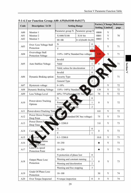
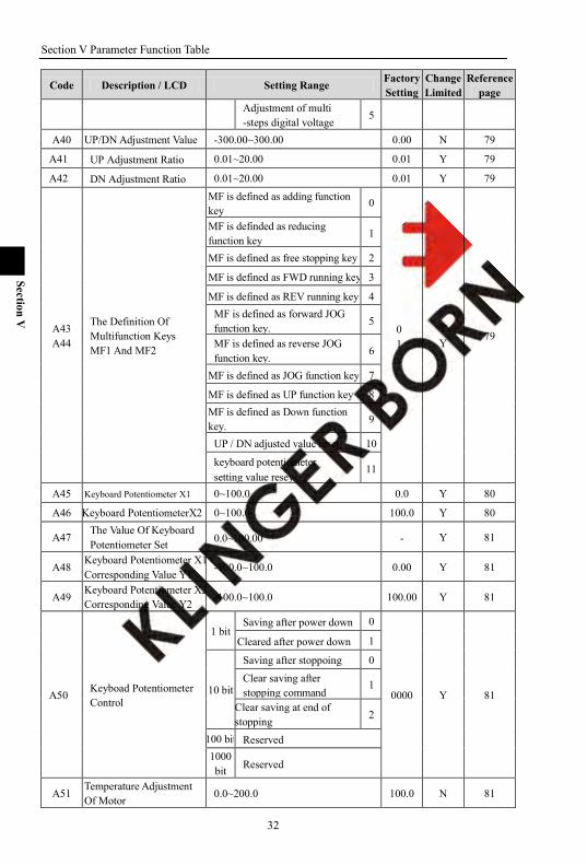
5-1-4. User Function Group:A00-A55(0x0100-0x0137)
Code Description / LCD Setting Range Factory Setting
Change Limited
Reference page
A00 A01 A02
Monitor 1 Monitor 2 Monitor 3
Parameter group N: Parameter group N: 0B00 0B01 0B02
Y Y Y
70 X1000/X100 X10/ bit
00~0B 0~63(0x00~0x3F)
A03 Over /Less Voltage Stall Protection
N 0 1 Y 71
Y 1
A04 Overvoltage Stall Protection Voltage
110%~140%( Standard bus voltage) 120 Y 71
A05 Auto Stablize Voltage
Invalid 0
0 Y 71 Valid 1
Valid, usless for deceleration 2
A06 Dynamic Braking option
Invalid 0
0 Y 71 Security Type 1
General Type 2
A07 Hysteresis voltage 0~10% 2 Y 72
A08 Dynamic Braking Voltage 110%~140%( Standard bus voltage) 130 Y 72
A09 Less Voltage Level 60%~75%(Standard DC bus voltage) 70 Y 72
A10 Power-down Tracking Options
N 0
0 Y 72 Power-off tracking mode 1
Startup tracking mode 2
A11 Power-down tTracking Time 0.0~20.0 0.0 Y 72
A12 Power Down Frequency Drop Point 65~100%(standard DC bus voltage) 75 Y 73
A13 Power Down Frequency Drop Time
0.1~3200.0 5.0 Y 73
A14 Current Limit N 0
0 Y 73 Y 1
A15 Limit Fall Time 0.1~3200.0 10.0 Y 73
A16 Limit Deceleration Protection Point 10~250 Y 73
A17 Limit Fix-speed Protection Point
10~250 Y 73
A18 Output Phase Lose Protection
N protection of phase lost 0
0 Y 73 Warning and constant running 1
Warning and deceleration 2
Warning and free stopping 3
A19 Grade Of Phase Lose Protection
10~100 30 Y 74
A20 Over Torque Inspected N torque inspection 0 0 Y 74

Section V Parameter Function Table
30
Section V
Code Description / LCD Setting Range Factory Setting
Change Limited
Reference page
Action Warning and running 1
Warning and decelerating stop 2
Warning and free stopping 3
A21 Over Torque Grade 10~250 Y 74
A22 Over Torque Inspection Time 0.0~60.0 0.1 Y 74
A23 Electronic Thermal Relay Protection Selection
N 0 1 Y 74
Y 1
A24 Electronic Thermal Protection Grade 120~250 Y 74
A25 Fault Reset Times 0~10 0 Y 75
A26 Fault Reset Time 0.5~20.0 1.0 Y 75
A27 Fan Startup Temperature 0.0~60.0 0.0 Y 75
A28 This Inverter Communication Address 1~128 8 Y 75
A29 Baud Rate
Baud rate is 1200 0
4 Y 75
Baud rate is 2400 1
Baud rate is 4800 2
Baud rate is 9600 3
Baud rate is 19200 4
Baud rate is 38400 5
A30 Communication Format
8, N, 1 for RTU 0
0 Y 76
8, N, 2 for RTU 1
8, E, 1 for RTU 2
8, O, 1 for RTU 3
8, E, 2 for RTU 4
8, O, 2 for RTU 5
A31 Communications Troubleshooting
N warning for communication fault 0
0 Y 76 Warning and running 1
Warning and decelerating stop 2
Warning and free stopping 3
A32 Delay Inspection Time 0: N inspection
10 Y 76 1~250: late inpsection
A33 Total Running Time Setting
Auto clear to zero after power on 0 1 Y 76 Continue to accumulate
running time after power on 1
A34 Unit Of Total Running Time
hour 0 0 Y 76
Day 1
Section V Parameter Function Table
31
Section V
Code Description / LCD Setting Range Factory Setting
Change Limited
Reference page
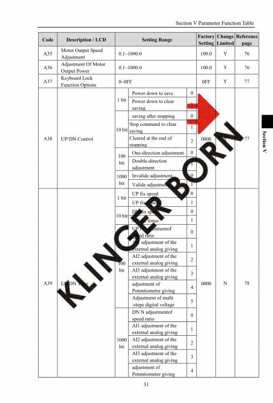
A35 Motor Output Speed Adjustment
0.1~1000.0 100.0 Y 76
A36 Adjustment Of Motor Output Power
0.1~1000.0 100.0 Y 76
A37 Keyboard Lock Function Options 0~0FF 0FF Y 77
A38 UP/DN Control
1 bit Power down to save 0
0000 Y 77
Power down to clear saving
1
10 bit
saving after stopping 0 Stop command to clear saving
1
Cleared at the end of stopping
2
100 bit
One-direction adjustment 0 Double-direction adjustment
1
1000 bit
Invalide adjustment 0
Valide adjustment 1
A39 UP/DN Time
1 bit UP fix speed 0
0000 N 78
UP fix times 1
10 bit DN fix speed 0
DN fix times 1
100 bit
UP N adjustmentof speed ratio
0
AI1 adjustment of the external analog giving 1
AI2 adjustment of the external analog giving 2
AI3 adjustment of the external analog giving
3
adjustment of Potentiometer giving
4
Adjustment of multi -steps digital voltage
5
1000 bit
DN N adjustmentof speed ratio
0
AI1 adjustment of the external analog giving 1
AI2 adjustment of the external analog giving 2
AI3 adjustment of the external analog giving
3
adjustment of Potentiometer giving
4
Section V Parameter Function Table
32
Section V
Code Description / LCD Setting Range Factory Setting
Change Limited
Reference page
Adjustment of multi -steps digital voltage
5
A40 UP/DN Adjustment Value -300.00~300.00 0.00 N 79
A41 UP Adjustment Ratio 0.01~20.00 0.01 Y 79
A42 DN Adjustment Ratio 0.01~20.00 0.01 Y 79
A43A44
The Definition Of Multifunction Keys MF1 And MF2
MF is defined as adding function key
0
0 1
Y Y
79
MF is definded as reducing function key
1
MF is defined as free stopping key 2
MF is defined as FWD running key 3
MF is defined as REV running key 4 MF is defined as forward JOG function key.
5
MF is defined as reverse JOG function key.
6
MF is defined as JOG function key. 7
MF is defined as UP function key 8 MF is defined as Down function key. 9
UP / DN adjusted value reset 10
keyboard potentiometer setting value resey
11
A45 Keyboard Potentiometer X1 0~100.0 0.0 Y 80
A46 Keyboard PotentiometerX2 0~100.0 100.0 Y 80
A47 The Value Of Keyboard Potentiometer Set 0.0~100.00 - Y 81
A48 Keyboard Potentiometer X1 Corresponding Value Y1
-100.0~100.0 0.00 Y 81
A49 Keyboard Potentiometer X2 Corresponding Value Y2 -100.0~100.0 100.00 Y 81
A50 Keyboad Potentiometer Control
1 bit Saving after power down 0
0000 Y 81
Cleared after power down 1
10 bit
Saving after stoppoing 0 Clear saving after stopping command 1
Clear saving at end of stopping
2
100 bit Reserved 1000 bit Reserved
A51 Temperature Adjustment Of Motor 0.0~200.0 100.0 N 81
Section V Parameter Function Table
33
Section V
Code Description / LCD Setting Range Factory Setting
Change Limited
Reference page
A52 Over-heat Temperature Of Motor
0.0~300.0 120.0 N 81
A53 Reaction For Motor Over-heat
N reaction for motor over-heat 0
0 Y 82 Warning and runing 1
Warning and deceleration stopping 2
Warning and free stopping 3
A54 Display of motor temperature -50.0~300.0 - N 82
A55 Proportion of Linkage Ratio 0.10~10.00 1.00 Y 82
5-1-5. IO function group:o00-o68(0x0200-0x0244)
Code Description / LCD Setting Range Factory Setting
Change Limited
Reference page
o00 AI1 Input X1 0~100.0 0.0 Y 82
o01 AI1 Input X2 0~100.0 100.0 Y 82
o02 AI2 Input X1 0~100.0 0.0 Y 82
o03 AI2 Input X2 0~100.0 100.0 Y 82
o04 AI3 Input X1 0~100.0 0.0 Y 82
o05 AI3 Input X2 0~100.0 100.0 Y 82
o06 AI1 Input X1 Corresponding Value Y1
-100.0~100.0 0.0 Y 82
o07 AI1 Input X2 Corresponding Value Y2
-100.0~100.0 100.0 Y 82
o08 AI2 Input X1 Corresponding Value Y1
-100.0~100.0 0.0 Y 82
o09 AI2 Input X2 Corresponding Value Y2
-100.0~100.0 100.0 Y 82
o10 AI3 Input X1 Corresponding Value Y1
-100.0~100.0 0.0 Y 82
o11 AI3 Input X2 Corresponding Value Y2
-100.0~100.0 100.0 Y 82
o12 AI1 Input Filter Time 0.00~2.00 0.10 Y 84
o13 AI2 Input Filter Time 0.00~2.00 0.10 Y 84
o14 AI3 Input Filter Time 0.00~2.00 0.10 Y 84
o15 o16
DA1 Output Terminal DA2 Output Terminal
N reaction 0
- -
Y Y
84
Setting frequency 1
Actual frequency 2
Actual current 3
Output voltage 4
DC bus voltge 5
Section V Parameter Function Table
34
Section V
Code Description / LCD Setting Range Factory Setting
Change Limited
Reference page
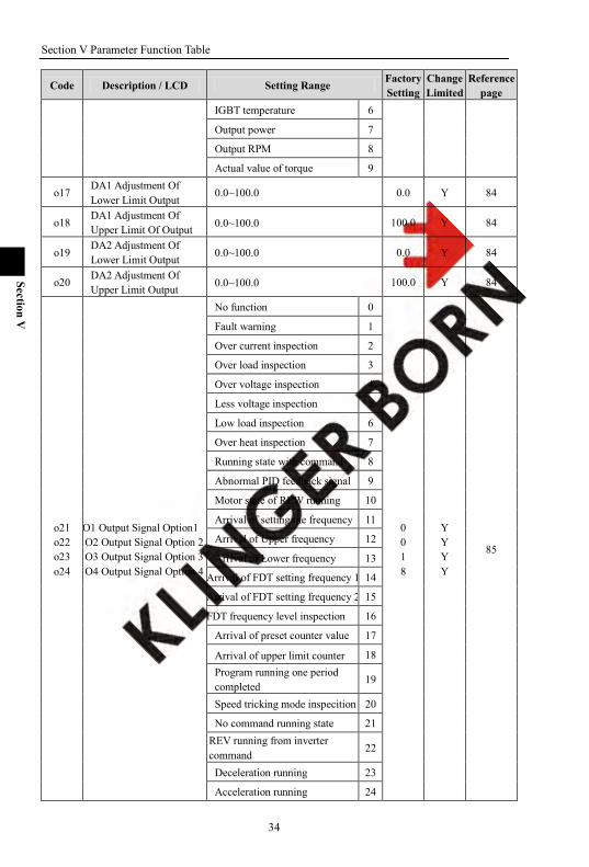
IGBT temperature 6
Output power 7
Output RPM 8
Actual value of torque 9
o17 DA1 Adjustment Of Lower Limit Output
0.0~100.0 0.0 Y 84
o18 DA1 Adjustment Of Upper Limit Of Output 0.0~100.0 100.0 Y 84
o19 DA2 Adjustment Of Lower Limit Output 0.0~100.0 0.0 Y 84
o20 DA2 Adjustment Of Upper Limit Output 0.0~100.0 100.0 Y 84
o21 o22 o23 o24
O1 Output Signal Option1 O2 Output Signal Option 2 O3 Output Signal Option 3 O4 Output Signal Option 4
No function 0
0 0 1 8
Y Y Y Y
85
Fault warning 1
Over current inspection 2
Over load inspection 3
Over voltage inspection 4
Less voltage inspection 5
Low load inspection 6
Over heat inspection 7
Running state with command 8
Abnormal PID feedback signal 9
Motor state of REW running 10
Arrival of setting the frequency 11
Arrival of Upper frequency 12
Arrival of Lower frequency 13
Arrival of FDT setting frequency 1 14
Arrival of FDT setting frequency 2 15
FDT frequency level inspection 16
Arrival of preset counter value 17
Arrival of upper limit counter 18 Program running one period completed
19
Speed tricking mode inspecition 20
No command running state 21 REV running from inverter command
22
Deceleration running 23
Acceleration running 24
Section V Parameter Function Table
35
Section V
Code Description / LCD Setting Range Factory Setting
Change Limited
Reference page
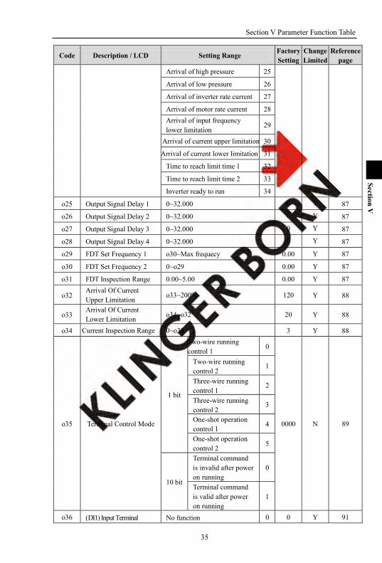
Arrival of high pressure 25
Arrival of low pressure 26
Arrival of inverter rate current 27
Arrival of motor rate current 28 Arrival of input frequency lower limitation
29
Arrival of current upper limitation 30
Arrival of current lower limitation 31
Time to reach limit time 1 32
Time to reach limit time 2 33
Inverter ready to run 34
o25 Output Signal Delay 1 0~32.000 0 Y 87
o26 Output Signal Delay 2 0~32.000 0 Y 87
o27 Output Signal Delay 3 0~32.000 0 Y 87
o28 Output Signal Delay 4 0~32.000 0 Y 87
o29 FDT Set Frequency 1 o30~Max frequecy 0.00 Y 87
o30 FDT Set Frequency 2 0~o29 0.00 Y 87
o31 FDT Inspection Range 0.00~5.00 0.00 Y 87
o32 Arrival Of Current Upper Limitation o33~200% 120 Y 88
o33 Arrival Of Current Lower Limitation o34~o32 20 Y 88
o34 Current Inspection Range 0~o33 3 Y 88
o35 Terminal Control Mode
1 bit
Two-wire running control 1
0
0000 N 89
Two-wire running control 2 1
Three-wire running control 1 2
Three-wire running control 2
3
One-shot operation control 1
4
One-shot operation control 2
5
10 bit
Terminal command is invalid after power on running
0
Terminal command is valid after power on running
1
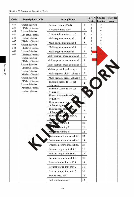
o36 (DI1) Input Terminal No function 0 0 Y 91
Section V Parameter Function Table
36
Section V
Code Description / LCD Setting Range Factory Setting
Change Limited
Reference page
o37 o38 o39 o40 o41 o42 o43 o44 o45 o46
Function Selection (DI2) Input Terminal Function Selection (DI3 )Input Terminal Function Selection (DI4) Input Terminal Function Selection (DI5) Input Terminal Function Selection (DI6) Input Terminal Function Selection (DI7) Input Terminal Function Selection (DI8) Input Terminal Function Selection (AI1) Input Terminal Function Selection (AI2) Input Terminal Function Selection (AI3) Input Terminal Function Selection
Forward running FWD 1 0 0 0 0 0 0 0 0 0 0
Y Y Y Y Y Y Y Y Y Y
Reverse running REV 2
3-line mode running STOP 3
Multi-segment command 1 4
Multi-segment command 2 5
Multi-segment command 3 6
Multi-segment command 7
Multi-segment speed command 1 8
Multi-segment speed command 9
Multi-segment speed command 3 10
Multi-segment digital voltage 1 11
Multi-segment digital voltage 2 12
Multi-segment digital voltage 3 13 The main set mode 1 of set frequency
14
The main set mode 2 of set frequency
15
The main set mode 3 of set frequency
16
The auxiliary setting mode 1 of frequency set
17
The auxiliary setting mode 2 of frequency set
18
The auxiliary setting mode 3 of frequency set
19
MSS time running 1 20
MSS time running 2 21
MSS time running 3 22
Operation control mode shift 1 23
Operation control mode shift 2 24
Operation control mode shift 3 25
Forward torque limit shift 1 26
Forward torque limit shift 2 27
Forward torque limit shift 3 28
Reverse torque limit shift 1 29
Reverse torque limit shift 2 30
Reverse torque limit shift 3 31
Torque speed shift 32
fault reset command 33

Section V Parameter Function Table
37
Section V
Code Description / LCD Setting Range Factory Setting
Change Limited
Reference page
FWD JOG command 34
REV JOG command 35
JOG order (as F35setting ) 36 Acceleration and deceleration prohibition command
37
Motor 1、2 shift 38
Free stop 39
Up command 40
Down command 41 Automation program running fuction cancel
42
Automation program running stop 43
Program running start mode 44
Program running stop mode 45
Pulse counter clearance 46
Pulse counter input 47
Counter loading 48
Upper counter loading 49 External default signal input (level) 50
1pump soft-start 51
1 pump stop 52
2pump soft-start 53
2 pump stop 54
3pump soft-start 55
3 pump stop 56
4pump soft-start 57
4 pump stop 58
handrotate command 59 Timing Water Supply change to zero
60
Extruder acceleration and deceleration direction
61
Extruder acceleration and deceleration allowable
62
Limit time 1 input 63
Limit time 2 input 64 Program switching to the next segment 65
UP/DN adjusted value reset 66
Section V Parameter Function Table
38
Section V
Code Description / LCD Setting Range Factory Setting
Change Limited
Reference page
Keyboard potentiometer set value reset
67
External default signal input (edge)
68
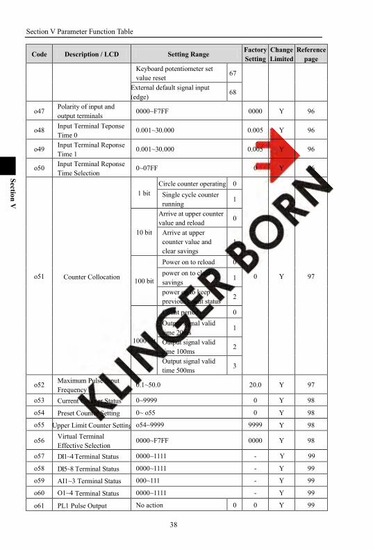
o47 Polarity of input and output terminals
0000~F7FF 0000 Y 96
o48 Input Terminal Teponse Time 0 0.001~30.000 0.005 Y 96
o49 Input Terminal Reponse Time 1 0.001~30.000 0.005 Y 96
o50 Input Terminal Reponse Time Selection
0~07FF 0 Y 96
o51 Counter Collocation
1 bit Circle counter operating 0
0 Y 97
Single cycle counter running 1
10 bit
Arrive at upper counter value and reload 0
Arrive at upper counter value and clear savings
1
100 bit
Power on to reload 0 power on to clear savings
1
power on to keep previous count status 2
1000 bit
Count period 0 Output signal valid time 20ms
1
Output signal valid time 100ms
2
Output signal valid time 500ms 3
o52 Maximum Pulse Input Frequency
0.1~50.0 20.0 Y 97
o53 Current Counter Status 0~9999 0 Y 98
o54 Preset Counter Setting 0~ o55 0 Y 98
o55 Upper Limit Counter Setting o54~9999 9999 Y 98
o56 Virtual Terminal Effective Selection
0000~F7FF 0000 Y 98
o57 DI1~4 Terminal Status 0000~1111 - Y 99
o58 DI5~8 Terminal Status 0000~1111 - Y 99
o59 AI1~3 Terminal Status 000~111 - Y 99
o60 O1~4 Terminal Status 0000~1111 - Y 99
o61 PL1 Pulse Output No action 0 0 Y 99
Section V Parameter Function Table
39
Section V
Code Description / LCD Setting Range Factory Setting
Change Limited
Reference page
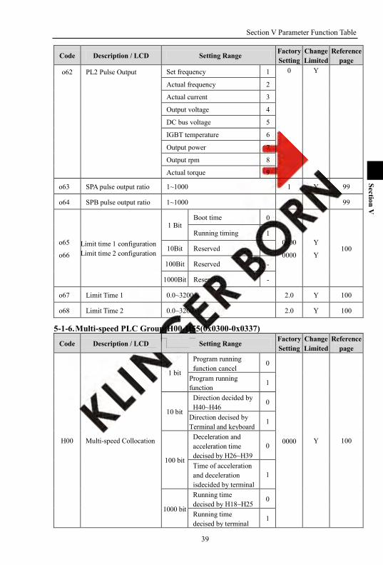
o62 PL2 Pulse Output Set frequency 1 0 Y
Actual frequency 2
Actual current 3
Output voltage 4
DC bus voltage 5
IGBT temperature 6
Output power 7
Output rpm 8
Actual torque 9
o63 SPA pulse output ratio 1~1000 1 Y 99
o64 SPB pulse output ratio 1~1000 1 Y 99
o65
o66 Limit time 1 configuration Limit time 2 configuration
1 Bit Boot time 0
0000
0000
Y
Y 100
Running timing 1
10Bit Reserved -
100Bit Reserved -
1000Bit Reserved -
o67 Limit Time 1 0.0~3200.0 2.0 Y 100
o68 Limit Time 2 0.0~3200.0 2.0 Y 100
5-1-6. Multi-speed PLC Group:H00-H55(0x0300-0x0337)
Code Description / LCD Setting Range Factory Setting
Change Limited
Reference page
H00 Multi-speed Collocation
1 bit
Program running function cancel
0
0000 Y 100
Program running function
1
10 bit
Direction decided by H40~H46 0
Direction decised by Terminal and keyboard
1
100 bit
Deceleration and acceleration time decised by H26~H39
0
Time of acceleration and deceleration isdecided by terminal
1
1000 bit
Running time decised by H18~H25
0
Running time decised by terminal
1
Section V Parameter Function Table
40
Section V
Code Description / LCD Setting Range Factory Setting
Change Limited
Reference page
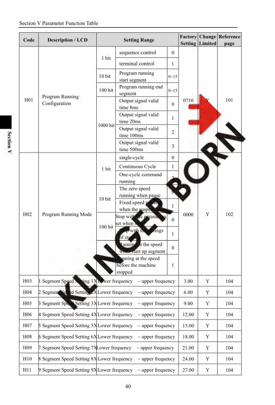
H01 Program Running Configuration
1 bit sequence control 0
0710 Y 101
terminal control 1
10 bit Program running start segment
0~15
100 bit Program running end segment 0~15
1000 bit
Output signal valid time 8ms 0
Output signal valid time 20ms 1
Output signal valid time 100ms 2
Output signal valid time 500ms 3
H02 Program Running Mode
1 bit
single-cycle 0
0000 Y 102
Continuous Cycle 1 One-cycle command running 2
10 bit
The zero speed running when pause
0
Fixed-speed running when the suspension
1
100 bit
Stop with the parameters set when stop
0
Stop with the settings of start up
1
1000 bit
Running at the speed when start up segment
0
Running at the speed before the machine stopped
1
H03 1 Segment Speed Setting 1X Lower frequency ~ upper frequency 3.00 Y 104
H04 2 Segment Speed Setting 2X Lower frequency ~ upper frequency 6.00 Y 104
H05 3 Segment Speed Setting 3X Lower frequency ~ upper frequency 9.00 Y 104
H06 4 Segment Speed Setting 4X Lower frequency ~ upper frequency 12.00 Y 104
H07 5 Segment Speed Setting 5X Lower frequency ~ upper frequency 15.00 Y 104
H08 6 Segment Speed Setting 6X Lower frequency ~ upper frequency 18.00 Y 104
H09 7 Segment Speed Setting 7X Lower frequency ~ upper frequency 21.00 Y 104
H10 8 Segment Speed Setting 8X Lower frequency ~ upper frequency 24.00 Y 104
H11 9 Segment Speed Setting 9X Lower frequency ~ upper frequency 27.00 Y 104

Section V Parameter Function Table
41
Section V
Code Description / LCD Setting Range Factory Setting
Change Limited
Reference page
H12 10 Segment Speed Setting 10X
Lower frequency ~ upper frequency 30.00 Y 104
H13 11 Segment Speed Setting 11X
Lower frequency ~ upper frequency 33.00 Y 104
H14 12 Segment Speed Setting 12X
Lower frequency ~ upper frequency 36.00 Y 104
H15 13 Segment Speed Setting 13X Lower frequency ~ upper frequency 39.00 Y 104
H16 14 Segment Speed Setting 14X Lower frequency ~ upper frequency 42.00 Y 104
H17 15 Segment Speed Setting 15X
Lower frequency ~ upper frequency 45.00 Y 104
H18 0 Segment Running Time T0
0.0~3200.0 2.0 Y 105
H19 1 Segment Running Time T1
0.0~3200.0 2.0 Y 105
H20 2 Segment Running Time T2
0.0~3200.0 2.0 Y 105
H21 3 Segment Running Time T3 0.0~3200.0 2.0 Y 105
H22 4 Segment Running Time T4 0.0~3200.0 2.0 Y 105
H23 5 Segment Running Time T5
0.0~3200.0 2.0 Y 105
H24 6 Segment Running Time T6
0.0~3200.0 2.0 Y 105
H25 7 Segment Running Time T7
0.0~3200.0 2.0 Y 105
H26 1 Segment Acceleration Time at1
0.0~3200.0 10.0 Y 105
H27 1 Segment Deceleration Time dt1 0.0~3200.0 10.0 Y 105
H28 2 Segment Acceleration Time at2 0.0~3200.0 10.0 Y 105
H29 2 Segment Deceleration Time dt2
0.0~3200.0 10.0 Y 105
H30 3 Segment Acceleration Time at3
0.0~3200.0 10.0 Y 105
H31 3 Segment Deceleration Time dt3
0.0~3200.0 10.0 Y 105
H32 4 Segment Acceleration Time at4
0.0~3200.0 10.0 Y 106
H33 4 Segment Deceleration Time dt4 0.0~3200.0 10.0 Y 106
H34 5 Segment Acceleration Time at5 0.0~3200.0 10.0 Y 106
H35 5 Segment Deceleration 0.0~3200.0 10.0 Y 106

Section V Parameter Function Table
42
Section V
Code Description / LCD Setting Range Factory Setting
Change Limited
Reference page
Time dt5
H36 6 Segment Acceleration Time at6 0.0~3200.0 10.0 Y 106
H37 6 Segment Deceleration Time dt6 0.0~3200.0 10.0 Y 106
H38 7 Segment Acceleration Time at7
0.0~3200.0 10.0 Y 106
H39 7 Segment Deceleration Time dt7
0.0~3200.0 10.0 Y 106
H40 H41 H42 H43 H44 H45 H46
1 Segment Speed Configuration Word 2 Segment Speed Configuration Word 3 Segment Speed Configuration Word 4 Segment Speed Configuration Word 5 Segment Speed Configuration Word 6 Segment Speed Configuration Word 7 Segment Speed Configuration Word
1 bit
Running direction: forward
0
0000 0000 0000 0000 0000 0000 0000
Y Y Y Y Y Y Y
106
Running direction: reverse
1
10 bit
Running time: *seconds 0
Running time: *munites 1
Running time: *hours 2
Running time: *days 3
100 bit
Acceleration time: *seconds
0
Acceleration time:*munites
1
Acceleration time: hours 2
Acceleration time: *days 3
1000 bit
Deceleration time: *seconds
0
Deceleration time: *munites 1
Deceleration time:*hours 2
Deceleration time: *days 3
H47 0 Segment Digital Voltage Giving
-100.0~100.0 0.0 Y 107
H48 1 Segment Digital Voltage Giving
-100.0~100.0 10.0 Y 107
H49 2 Segment Digital Voltage Giving
-100.0~100.0 20.0 Y 107
H50 3 Segment Digital Voltage Giving
-100.0~100.0 30.0 Y 108
H51 4 Segment Digital Voltage Giving
-100.0~100.0 40.0 Y 108
H52 5 Segment Digital Voltage Giving
-100.0~100.0 50.0 Y 108
H53 6 Segment Digital Voltage Giving
-100.0~100.0 60.0 Y 108

Section V Parameter Function Table
43
Section V
Code Description / LCD Setting Range Factory Setting
Change Limited
Reference page
H54 7 Segment Digital Voltage Giving
-100.0~100.0 70.0 Y 108
H55 Multi-speed Status
1 bit Current speed step 0~0xF
- N 108 10 bit
Current acceleration segment
0~0x7
100 bit Current running time segment
0~0x7
1000 bit Current digit voltage segment
0~0x7
5-1-7. V/Fcurve Group:U00-U15(0x0400-0x040F)
Code Description / LCD Setting Range Factory Setting
Change Limited
Reference page
U00 V/ Setting Frequency1 0.00~U02 5.00 N 108
U01 V/F Setting Voltage 1 0~U03 10 N 108
U02 V/F Setting Frequency 2 U00~U04 10.00 N 109
U03 V/F Setting Voltage 2 U01~U05 20 N 109
U04 V/F Setting Frequency 3 U02~U06 15.00 N 109 U05 V/F Setting Voltage 3 U03~U07 30 N 109 U06 V/F Setting Frequency 4 U04~U08 20.00 N 109 U07 V/F Setting Voltage 4 U05~U09 40 N 109 U08 V/F Setting Frequency 5 U06~U10 25.00 N 109 U09 V/F Setting Voltage 5 U07~U11 50 N 109 U10 V/F Setting Frequency 6 U08~U12 30.00 N 109 U11 V/F Setting Voltage 6 U09~U13 60 N 109 U12 V/F Setting Frequency 7 U10~U14 35.00 N 109 U13 V/F Setting Voltage 7 U11~U15 70 N 109 U14 V/F Setting Frequency 8 U12~most frequency 40.00 N 109 U15 V/F Setting Voltage 8 U13~100 80 N 109
5-1-8. PID parameter:P00-P12(0x0500-0x050C)
Code Description / LCD Setting Range Factory Setting
Change Limited
Reference page
P00 PID Configuration
1 bit Unidirectional regulation
0
0000 N 109
Bidirectional regulation 1
10 bit Negative effect 0
Positive effect 1
100 bit PID fault, N action 0
Warning & Continuous running
1
Section V Parameter Function Table
44
Section V
Warning & Decelerating stop
2
Warning & Free stop 3
1000 bit - -
- -
P01 PID Output Limit 0~100 100 Y 110
P02 Feedback Signal Selection
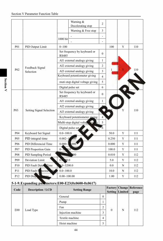
Set frequency by keyboard or RS485
0
1 Y 110
AI1 external analogy giving 1
AI2 external analogy giving 2
AI3 external analogy giving 3 Keyboard potentiometer giving 4
muti-step digital voltage giving 5
Digital pulse set 6
P03 Setting Signal Selection
Set frequency by keyboard or RS485
0
2 Y 110
AI1 external analogy giving 1
AI2 external analogy giving 2
AI3 external analogy giving 3
Keyboard potentiometer giving 4
Multi-step digital voltage giving 5
Digital pulse set 6
P04 Keyboard Set Signal 0.0~100.0 50.0 Y 111
P05 PID integral time 0.002~10.000 0.250 Y 111
P06 PID Differencial Time 0.000~10.000 0.000 Y 111
P07 PID Proportion Gain 0~1000.0 100.0 Y 111
P08 PID Sampling Period 0.002~10.000 0.010 Y 112
P09 Deviation Limit 0.0~20.0 5.0 Y 112
P10 PID Fault Detect Time 0.0~3200.0 0.0 N 112
P11 PID Fault Detected Value 0.0~100.0 10.0 N 112
P12 PID Display Range 0.00~100.00 1.00 Y 112
5-1-9. Expanding parameters:E00-E23(0x0600-0x0617)
Code Description / LCD Setting Range Factory Setting
Change Limited
Reference page
E00 Load Type
General 0
0 N 112
Pump 1
Fan 2
Injection machine 3
Textile machine 4
Hoist machine 5
Section V Parameter Function Table
45
Section V
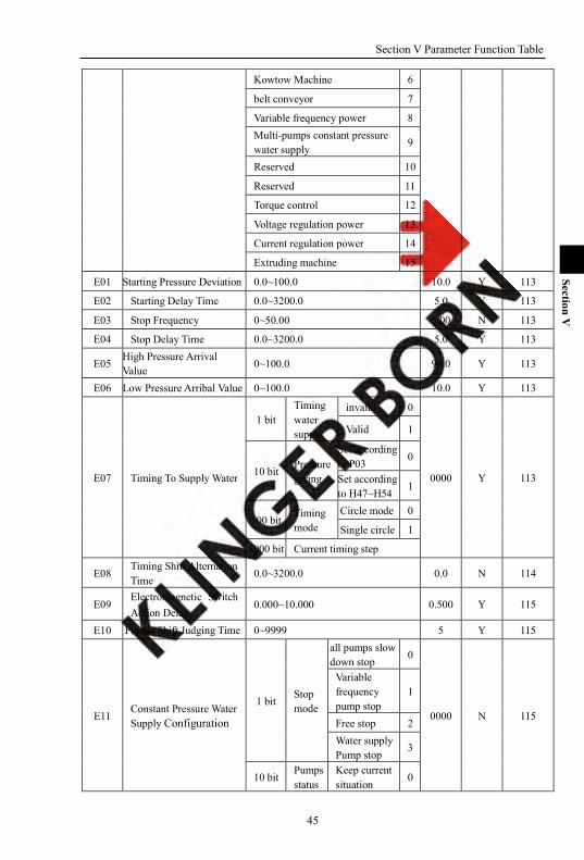
Kowtow Machine 6
belt conveyor 7
Variable frequency power 8 Multi-pumps constant pressure water supply 9
Reserved 10
Reserved 11
Torque control 12
Voltage regulation power 13
Current regulation power 14
Extruding machine 15
E01 Starting Pressure Deviation 0.0~100.0 10.0 Y 113
E02 Starting Delay Time 0.0~3200.0 5.0 Y 113
E03 Stop Frequency 0~50.00 5.00 N 113
E04 Stop Delay Time 0.0~3200.0 5.0 Y 113
E05 High Pressure Arrival Value 0~100.0 90.0 Y 113
E06 Low Pressure Arribal Value 0~100.0 10.0 Y 113
E07 Timing To Supply Water
1 bit Timing water supply
invalid 0
0000 Y 113
Valid 1
10 bit Pressure giving
Set according to P03
0
Set according to H47~H54
1
100 bit Timing mode
Circle mode 0
Single circle 1
1000 bit Current timing step
E08 Timing Shift Alternation Time
0.0~3200.0 0.0 N 114
E09 Electromagnetic Switch Action Delay
0.000~10.000 0.500 Y 115
E10 Pumps Shift Judging Time 0~9999 5 Y 115
E11 Constant Pressure Water Supply Configuration
1 bit Stop mode
all pumps slow down stop 0
0000 N 115
Variable frequency pump stop
1
Free stop 2 Water supply Pump stop
3
10 bit Pumps status
Keep current situation
0

Section V Parameter Function Table
46
Section V
when fault occurs
All-pumps stop 1
100 bit
Alternation shift mode
Variable frequency to working frequency
0
Variable frequency to stop
1
1000 bit Pump status keep
Keep status 0
Stop reset 1
E12 Multi-pumps Configuration
1 bit
Pump 1 invalid 0
0001 N 117
Pump 1 variable frequency to control pump
1
Pump 1 soft starts to control pump
2
10 bit
Pump 2 invalid 0 Pump 2 variable frequency to control pump
1
Pump 2 soft starts to control pump
2
100 bit
Pump 3 invalid 0 Pump 3 variable frequency to control pump
1
Pump 3 soft starts to control pump
2
1000 bit
Pump 4 invalid 0 Pump 4 variable frequency to control pump
1
Pump 4 soft starts to control pump
2
E13 Multi-pumps Status
1 bit
Pump 1 stop 0
0000 N 117
Pump 1 run in variable frequency 1
Pump 1 run in working frequency
2
10 bit
Pump 2 stop 0 Pump 2 run in variable frequency 1
Pump 2 run in working frequency
2

Section V Parameter Function Table
47
Section V
100 bit
Pump 3 stop 0 Pump 3 run in variable frequency
1
Pump 3 run in working frequency 2
1000 bit
Pump 4 stop 0 Pump 4 run in variable frequency
1
Pump 4 run in working frequency 2
E14 Soft Starting Pump Control
1 bit
Pump 1 soft-no command 0
0000 Y 118
Pump 1 soft-stop 1
Pump 1 soft-start 2
10 bit
Pump 1 soft-no command 0
Pump 2 soft-stop 1
Pump 2 soft-start 2
100 bit
Pump 1 soft-no command 0
Pump 3 soft-stop 1
Pump 3 soft-start 2
1000 bit
Pump 1 soft-no command 0
Pump 4 soft-stop 1
Pump 4 soft-start 2
E15 User Parameter 0 0~9999 0 Y 118
E16 User Parameter 1 0~9999 0 Y 118 E17 User Parameter 2 0~9999 0 Y 118 E18 User Parameter 3 0~9999 0 Y 118 E19 User Parameter 4 0~9999 0 Y 118 E20 User parameter 5 0~9999 0 Y 118 E21 User Parameter 6 0~9999 0 Y 118 E22 User Parameter 7 0~9999 0 Y 118 E23 User Parameter 8 0~9999 0 Y 118
5-1-10. Speed-loop parameter [SPD]:C00-C31(0x0700-0x071F)
Code Description / LCD Setting Range Factory Setting
Change Limited
Reference page
C00 Filter Time Of Speed-loop 2~200 10 Y 118
C01 Speed-loop Low Speed Ti 0.01~100.00 0.25 Y 118
C02 Speed-loop Low Speed Td 0.000~1.000 0.000 Y 118
C03 Speed-loop Low Speed P 0~150 100 Y 119
C04 Speed-loop Low Speed Shift Frequency
0.0~C08 7.00 Y 119

Section V Parameter Function Table
48
Section V
C05 Speed Loop High Speed Ti 0.01~100.00 0.50 Y 119
C06 Speed Loop High Speed Td 0.000~1.000 0.000 Y 119
C07 Speed Loop High Speed P 0~150 75 Y 119
C08 Speed Loop And High-speed Switching Frequency
C04~max frequency 30.00 Y 119
C09 Low-speed Slip Gain 0~200 100 Y 119
C10 Low Speed Slip Switching Frequency
0~C12 5.00 Y 119
C11 High Speed Slip Gain 0~200 100 Y 119
C12 High Speed Slip Switching Frequency C10~ max frequency 30.00 Y 119
C13 Upper Froward Torque 0.0~300.0 250.0 Y 119
C14 Upper Reverse Torque 0.0~300.0 250.0 Y 120
C15 Forward Torque setting mode
1 bit Setting mode
Set by keyboard or rs485 0
0000 Y 120
AI1 external analogy giving
1
AI2 external analogy giving
2
AI3 external analogy giving
3
Keypad potentiometer giving
4
Multi-step digital voltage giving
5
Digital pulse set 6
10 bit direction Direction uncontrolled 0
Direction controlled 1
C16 Reverse Torque setting mode
1 bit Setting mode
Set by keyboard or RS485 0
0000 Y 120
AI1 external analogy 1
AI2 external analogy giving
2
AI3 external analogy giving
3
Keypad potentiometer giving
4
Multi-step digital voltage giving
5
Digital pulse set 6
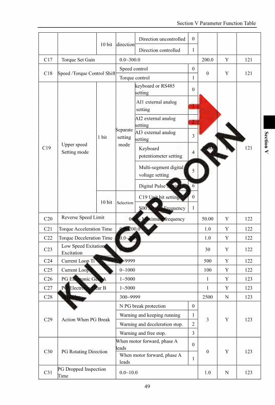
Section V Parameter Function Table
49
Section V
10 bit direction Direction uncontrolled 0
Direction controlled 1
C17 Torque Set Gain 0.0~300.0 200.0 Y 121
C18 Speed /Torque Control Shift Speed control 0
0 Y 121 Torque control 1
C19 Upper speed Setting mode
1 bit Separate setting mode
keyboard or RS485 setting
0
0000 Y 121
AI1 external analog setting
1
AI2 external analog setting
2
AI3 external analog setting 3
Keyboard potentiometer setting
4
Multi-segment digital voltage setting
5
Digital Pulse Setting 6
10 bit Selection C19 Unit bit setting 0
S00 Setting Frequency 1
C20 Reverse Speed Limit 0.00~ Maximum frequency 50.00 Y 122
C21 Torque Acceleration Time 0.0~200.0 1.0 Y 122
C22 Torque Deceleration Time 0.0~200.0 1.0 Y 122
C23 Low Speed Exitation Excitation 0~100 30 Y 122
C24 Current Loop Ti 0~9999 500 Y 122
C25 Current Loop P 0~1000 100 Y 122
C26 PG Electronic Gear A 1~5000 1 Y 123
C27 PG Electronic Gear B 1~5000 1 Y 123
C28 PG Pulse 300~9999 2500 N 123
C29 Action When PG Break
N PG break protection 0
3 Y 123 Warning and keeping running 1
Warning and deceleration stop. 2
Warning and free stop. 3
C30 PG Rotating Direction
When motor forward, phase A leads
0 0 Y 123
When motor forward, phase A leads
1
C31 PG Dropped Inspection Time 0.0~10.0 1.0 N 123

Section V Parameter Function Table
50
Section V
5-1-11. Motor parameter [MOT]:b00-b22(0x0800-0x0816)
Code Description / LCD Setting Range Factory Setting
Change Limited
Reference page
b00 Motor 1 Rated Frequency 0.00~Maximum frequency 50.00 Y 123
b01 Motor 1 Rated Current y09*(50%~100%) Y 123
b02 Motor 1 Rated Voltage 100~1140 Y 123
b03 Motor 1 Pole-pairs 1~8 2 Y 123
b04 Motor 1 Rated Speed 500~5000 1480 Y 123
b05 Motor 1 N Load Current 0.0~b01 Y 124
b06 Motor 1 Stator Resistance 0.000~30.000 Y 124
b07 Motor 1 Rotor Resistance 0.000~30.000 Y 124
b08 Motor 1 Stator Inductance 0.0~3200.0 Y 124
b09 Motor 1 Mutual Inductance 0.0~3200.0 Y 124
b10 Motor Selection Motor 1 0
0 N 124 Motor 2 1
b11 Motor Parameter Measurement
No measurement 0
0 N 124 calculate by label data 1
inverter static measurement 2
inverter rotation measurement 3
b11 Motor Parameter Measurement
No measurement 0
0 N 124 calculate by label data 1
inverter static measurement 2
inverter rotation measurement 3
b12 Vector Control initial Inspection R1
Not inspection R1 0 0 N 125
Inspection R1 1
b13 Motor 2 Rated Frequency 0.00~Maxmum frequency 50.00 Y 125
b14 Motor 2 Rated Current y09*(50%~100%) Y 125 b15 Motor 2 Rated Voltage 100~1140 Y 125 b16 Motor 2 Pole Pairs 1~8 2 Y 125 b17 Motor 2 Rated Speed 500~5000 1480 Y 125 b18 Motor 2 N Load Current 0.0~b14 Y 125 b19 Motor 2 Stator Resistance 0.000~30.000 Y 125 b20 Motor 2 Rotator Resistance 0.000~30.000 Y 125 b21 Motor 2 Stator Inductance 0.0~3200.0 Y 125 b22 Motor 2 Mutual Inductance 0.0~3200.0 Y 125
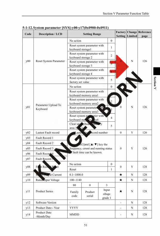
Section V Parameter Function Table
51
Section V
5-1-12. System parameter [SYS]:y00-y17(0x0900-0x0911)
Code Description / LCD Setting Range Factory Setting
Change Limited
Reference page
y00 Reset System Parameter
No action 0
0 N 126
Reset system parameter with keyboard storage1 1
Reset system parameter with keyboard storage 2 2
Reset system parameter with keyboard storage 3
3
Reset system parameter with keyboard storage 4
4
Reset system parameter with factory set value
5
y01 Parameter Upload To Keyboard
No action 0
0 N 126
Reset system parameter with keyboard memory area1
1
Reset system parameter with keyboard memory area2
2
Reset system parameter with keyboard memory area3
3
Reset system parameter with keyboard memory area4 4
Clear up keyboard memory area 1, 2, 3, 4 5
y02 Lastest Fault record Lastest fault record number 0 Y 126
y03 Fault Record 1
Press [PRG]and [/] key the frequency, crrent and running status of fault time can be known.
0 Y 126
y04 Fault Record 2
y05 Fault Record 3
y06 Fault Record 4
y07 Fault Record 5
y08 Fault Record Reset No action 0
0 Y 128 Reset 1
y09 Rated Output Current 0.1~1000.0 N 128
y10 Rated Input Voltage 100~1140 N 128
y11 Product Series
80 0 3
N 128 Family code
Product serial
Input oltage
grade 1 y12 Software Version - - N 128
y13 Product Date-- Year YYYY - N 128
y14 Product Date -Month/Day
MMDD - N 128
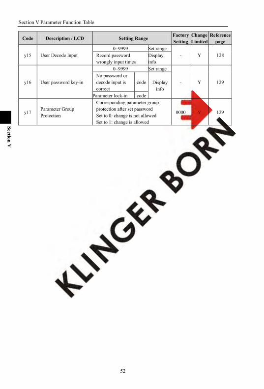
Section V Parameter Function Table
52
Section V
Code Description / LCD Setting Range Factory Setting
Change Limited
Reference page
y15 User Decode Input 0~9999 Set range
- Y 128 Record password wrongly input times
Display info
y16 User password key-in
0~9999 Set range
- Y 129 No password or decode input is correct
code Display info
Parameter lock-in code
y17 Parameter Group Protection
Corresponding parameter group protection after set password Set to 0: change is not allowed Set to 1: change is allowed
0000 Y 129
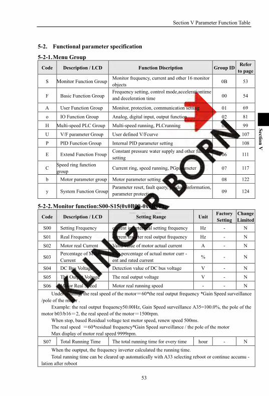
Section V Parameter Function Table
53
Section V
5-2. Functional parameter specification
5-2-1. Menu Group
Code Description / LCD Function Discription Group ID Refer
to page
S Monitor Function Group Monitor frequency, current and other 16 monitor objects 0B 53
F Basic Function Group Frequency setting, control mode,accelerationtime and deceleration time 00 54
A User Function Group Monitor, protection, communication setting 01 69
o IO Function Group Analog, digital input, output function 02 81
H Multi-speed PLC Group Multi-speed running, PLCrunning 03 99
U V/F parameter Group User defined V/Fcurve 04 107
P PID Function Group Internal PID parameter setting 05 108
E Extend Function Froup Constant pressure water supply and other functions setting 06 111
C Speed ring function group
Current ring, speed running, PGparameter 07 117
b Motor parameter group Motor parameter setting 08 122
y System Function Group Parameter reset, fault query, product information, parameter protection 09 124
5-2-2. Monitor function:S00-S15(0x0B00-0x0B0F)
Code Description / LCD Setting Range Unit Factory Setting
Change Limited
S00 Setting Frequency current inverter real setting frequency Hz - N
S01 Real Frequency current inverter real output frequency Hz - N
S02 Motor real Current Valid value of motor actual current A - N
S03 Percentage of Motor Current
The percentage of actual motor curr - ent and rated current
% - N
S04 DC Bus Voltage Detection value of DC bus voltage V - N
S05 The Output Voltage The real output voltage V - N
S06 Motor Real Speed Motor real running speed - - N Under running, the real speed of the motor=60*the real output frequency *Gain Speed surveillance
/pole of the motor . Example: the real output frequency50.00Hz, Gain Speed surveillance A35=100.0%, the pole of the
motor b03/b16=2, the real speed of the motor=1500rpm. When stop, based Residual voltage test motor speed, renew speed 500ms. The real speed =60*residual frequency*Gain Speed surveillance / the pole of the motor Max display of motor real speed 9999rpm.
S07 Total Running Time The total running time for every time hour - N
When the ouptput, the frequency inverter calculated the running time. Total running time can be cleared up automatically with A33 selecting reboot or continue accumu -
lation after reboot
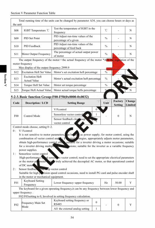
Section V Parameter Function Table
54
Section V
Total running time of the units can be changed by parameter A34, you can choose hours or days as the unit
S08 IGBT Temperature Test the temperature of IGBT in the frequency
- N
S09 PID Set Point PID Adjust run-time values of the percentage of a given
% - N
S10 PID Feedback PID Adjust run-time values of the percentage of feed back
% - N
S11 Motor Output Frequency The percentage of actual output power of motor % - N
The output frequency of the motor=the actual frequency of the motor *A36 the regulation of the motor frequency
Max display of the output frequency 2999.9 S12 Excitation Heft Set Value Motor‘s set excitation heft percentage % - N
S13 Excitation Heft Actual Value
Motor‘s actual excitation heft percentage % - N
S14 Torque Heft Set Value Motor set torque percentage % - N
S15 Torque Heft Actual Value Motor actual torque hefts percentage % - N
5-2-3. Basic function Group:F00-F50(0x0000-0x0032)
Code Description / LCD Setting Range Unit Factory Setting
Change Limited
F00 Control Mode
V/Fcontrol 0
- 0 N Sensorless vector control 1 Sensor feedback close loop vector control
2
Control mode choose, setting 0~2. 0 : V/ Fcontrol
It is not sensitive to motor parameters, can be used as power supply; for motor control, using the combination of vector control and V / F control strategies, appropriately adjusts motor parameters, obtain high-performance control effect; suitable for a inverter driving a motor occasions; suitable for a inverter driving multiple motors occasions; suitable for the inverter as a variable frequency power supplies.
1 : Sensorless vector control High-performance speed sensorless vector control; need to set the appropriate electrical parameters or the motor parameter tuning; truly achieved the decoupled AC motor, so that operational control of DC motors.
2 : Sensor feedback close loop vector control Suitable for high precision speed control occasions, need to install PG card and pulse encoder shaft in the motor or mechanical equipment.
F01 Keyboard Setting Frequency Lower frequency~upper frequency Hz 50.00 Y
The keyboard for a given operating frequency,it can be any frequency between lower frequency and upper frequency .
F02/F03setting to 0, Involved in setting frequency calculation.
F02 Frequency Main Set Mode
Keyboard setting frequency or RS485 0
- 0 Y AI1 the external analog setting 1
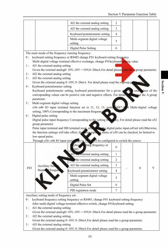
Section V Parameter Function Table
55
Section V
AI2 the external analog setting 2
AI3 the external analog setting 3
Keyboard potentiometer setting 4 Multi-segment digital voltage setting 5
Digital Pulse Setting 6 The main mode of the frequency running frequency: 0 : keyboard setting frequency or RS485 change F01 keyboard setting frequency
Multi-digital voltage terminal effective exchange, change F01keyboard setting value 1 : AI1 the external analog setting
Given the external analog0~10V,-10V~+10V,0~20mA.For detail please read the o group parameter. 2 : AI2 the external analog setting 3 : AI3 the external analog setting
Given the external analog 0~10V, 0~20mA. For detail please read the o group parameter. 4 : Keyboard potentiometer setting
Keyboard potentiometer setting, keyboard potentiometer for a given start and end values of the corresponding values can be positive role and negative effects. For detail please read the A group parameter.
5 : Multi-segment digital voltage setting o36~o46 IO input terminal function set to 11, 12, 13, switch H47~H54 Multi-digital voltage setting, 100% Corresponding to the maximum frequency .
6 : Digital pulse setting Digital pulse input frequency Corresponding to the setting frequency, For detail please read the o52 group parameter. Pulse input terminal and DI8 terminal reset, after using the digital pulse input,o43set to0,Otherwise, the function settings will take effect, the pulse input on status of o58 can be checked, be limited to low-speed pulse. Through o36~o46 IO input teminal set to 14, 15, 16 be configured to switch the source
F03 Auxiliary Setting Mode Of Frequency
Keyboard setting frequency or RS485
0
- 0 Y
AI1 the external analog setting 1
AI2 the external analog setting 2
AI3 the external analog setting 3
Keyboard potentiometer setting 4 Multi-segment digital voltage setting
5
Digital Pulse Set 6
PID regulation mode 7 Auxiliary setting mode of frequency set: 0 : keyboard frequency setting frequency or RS485, change F01 kayboard setting frequency
After multi-digital voltage terminal effective switch, change F01keyboard setting. 1 : AI1 the external analog setting
Given the external analog0~10V,-10V~+10V,0~20mA.For detail please read the o group parameter. 2 : AI2 the external analog setting
Given the external analog 0~10V, 0~20mA.For detail please read the o group parameter. 3 : AI3 the external analog setting
Given the external analog 0~10V, 0~20mA.For detail please read the o group parameter.
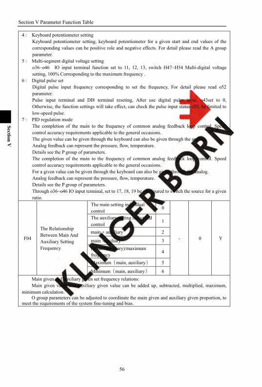
Section V Parameter Function Table
56
Section V
4 : Keyboard potentiometer setting Keyboard potentiometer setting, keyboard potentiometer for a given start and end values of the corresponding values can be positive role and negative effects. For detail please read the A group parameter.
5 : Multi-segment digital voltage setting o36~o46 IO input terminal function set to 11, 12, 13, switch H47~H54 Multi-digital voltage setting, 100% Corresponding to the maximum frequency .
6 : Digital pulse set Digital pulse input frequency corresponding to set the frequency, For detail please read o52 parameter. Pulse input terminal and DI8 terminal reseting, After use digital pulse input, o43set to 0, Otherwise, the function settings will take effect, can check the pulse input status o58, be limited to low-speed pulse.
7 : PID regulation mode The completion of the main to the frequency of common analog feedback loop control. Speed control accuracy requirements applicable to the general occasions. The given value can be given through the keyboard can also be given through the analog. Analog feedback can represent the pressure, flow, temperature. Details see the P group of parameters. The completion of the main to the frequency of common analog feedback loop control. Speed control accuracy requirements applicable to the general occasions. For a given value can be given through the keyboard can also be given through the analog. Analog feedback can represent the pressure, flow, temperature. Details see the P group of parameters. Through o36~o46 IO input terminal, set to 17, 18, 19 be configured to switch the source for a given ratio.
F04
The Relationship Between Main And Auxiliary Setting Frequency
The main setting individual control
0
- 0 Y
The auxiliary setting individual control
1
main + auxiliary 2
main -auxiliary 3 (main *auxiliary)/maximum frequency 4
Maximum{main, auxiliary} 5
Minimum{main, auxiliary} 6 Main given and auxiliary given set frequency relations: Main given value and auxiliary given value can be added up, subtracted, multiplied, maximum,
minimum calculation. O group parameters can be adjusted to coordinate the main given and auxiliary given proportion, to
meet the requirements of the system fine-tuning and bias.
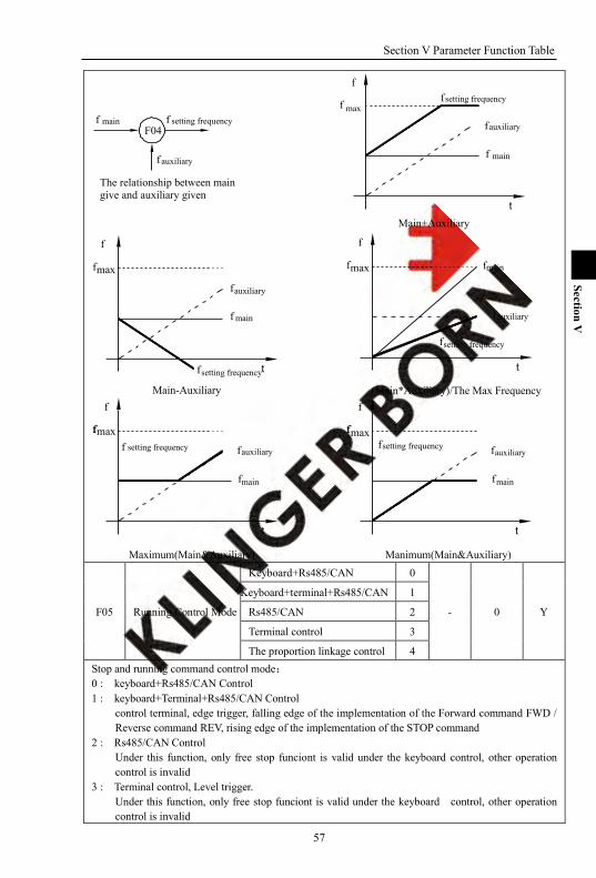
Section V Parameter Function Table
57
Section V
F04
t
f f
f
f
f
max
main
auxiliary
setting frequency
main
auxiliary
setting frequencyf f
f
The relationship between main give and auxiliary given
Main+Auxiliary
Main-Auxiliary
f
f
f t
f
maxf
auxiliary
main
setting frequency
(Main*Auxiliary)/The Max Frequency
f
f
f
f
maxf
t
setting frequency
auxiliary
main
main
max
Maximum(Main&Auxiliary)
f
f
fff
t
fsetting frequency auxiliary
main
max
Manimum(Main&Auxiliary)
t
f
f
f
f
ff
setting frequencyauxiliary
F05 Running Control Mode
Keyboard+Rs485/CAN 0
- 0 Y
Keyboard+terminal+Rs485/CAN 1
Rs485/CAN 2
Terminal control 3
The proportion linkage control 4 Stop and running command control mode: 0 : keyboard+Rs485/CAN Control 1 : keyboard+Terminal+Rs485/CAN Control
control terminal, edge trigger, falling edge of the implementation of the Forward command FWD / Reverse command REV, rising edge of the implementation of the STOP command
2 : Rs485/CAN Control Under this function, only free stop funciont is valid under the keyboard control, other operation control is invalid
3 : Terminal control, Level trigger. Under this function, only free stop funciont is valid under the keyboard control, other operation control is invalid

Section V Parameter Function Table
58
Section V
4 : The proportion linkage control Select this function, the slave unit would execute the command from the proportion linkage host unit. Select this function, can also use keyboard, terminal, RS485 to control the proportion linkage slave unit to run. The proportion of linkage running,after stop the proportion linkage slave unit with the keyboard
terminal, Rs485, the slave unit will not run the proportion liknge host unit‘s command, it needs once again to respond to host commands through the keyboard, terminal, RS485, or the proportion linkage host sends stop command so that slave unit could respond to run commands.
F06 V/F Boost Mode
1 bit
Beeline V/Fcurve 0
- 0000 N
Power of 1.2 V/Fcurve 1 Power of 1.7 power V/Fcurve
2
Power of 2 powerV/Fcurve
3
Define mode V/Fcurve 4
10 bit Close Automatic torque boost 0
Automatic torqueboost 1
100 bit VF mode 0 Speed No Output 0
VF mode keep 0 speed 1 1 Bit: V/F promote curve
0 Line V/F curve: Suitable for ordinary constant torque load 1 Power of 1.2 V/F curve: Appropriate torque down V/F curve, Suitable for liquid loads 2 Power of 1.7 V/F curve: Appropriate torque down V/F curve, Suitable for liquid loads 3 Power of 2 V/F curve: Torque down V/F curve, It is suitable for fans, pumps, centrifugal load 4 Define mode V/Fcurve: Can be customized appropriate curve according to the actual situation .
10 bit: Auto-torque boost mode 0 Close Automatic torque boost 1 Open automatic torque boost
parameters which affect automatic torque enhance : Actual value torque component S15 b06/b19 stator resistance F07 torque enhance value Automatic torque enhance value = actual value of torque component * stator resistance *torque enhance value.
100 bit: VF mode 0 speed maintain function 0 VF mode 0 Speed No Output: Output frequency is less than 0.5Hz, stop PWM output to reduce the switching loss. 1 VF mode keep 0 speed: the output frequency is 0Hz, in accordance with the DC braking current of starting F26, keep 0 speed.
F07 Torque boost Value 0.0~30.0% % 0.0 Y
F08 Torque Boost Cut-off Frequency
0.00~Maximum frequency Hz 15.00 Y
Torque increase is mainly used to improve the low-frequency torque characteristics under sensorless -V / F control mode.
Torque boost is too low, weak low speed motor
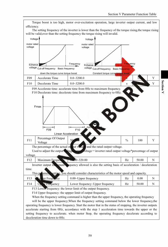
Section V Parameter Function Table
59
Section V
Torque boost is too high, motor over-excitation operation, large inverter output current, and low efficiency.
The setting frequency of the inverter is lower than the frequency of the torque rising,the torque rising will be valid;over than the setting frequency the torque rising will invalid.
Frequency Frequency
motor rated voltage
Enhance voltage Basic frequency
Voltage
down the torque curve torque boost
Cut-off frequency
Constant torque curve torque boost
motor rated voltage
Enhance voltage Basic frequency
Voltage
Cut-off frequency
F09 Accelerate Time 0.0~3200.0 s 10.0 Y
F10 Decelerate Time 0.0~3200.0 s 10.0 Y
F09 Accelerate time: accelerate time from 0Hz to maximum frequency. F10 Decelerate time: decelerate time from maximum frequency to 0Hz.
F10F09
Fmax
running time
Linear Acceleration
F11 Percentage Of Output Voltage
50~110 % 100 Y
The percentage of the actual output voltage and the rated output voltage. Used to adjust the output voltage,output voltage=inverter rated output voltage*percentage of output
voltage. F12 Maximum Frequency 10.00~320.00 Hz 50.00 N
Inverter output maximum frequency allowed is also the setting basis of acceleration / deceleration time.
This parameter setting, you should consider characteristics of the motor speed and capacity. F13 Lower Frequency 0.00~Upper frequency Hz 0.00 N
F14 Upper Frequency Lower frequency~Upper frequency Hz 50.00 N F13 Lower frequency: the lower limit of the output frequency. F14 Upper frequency: the uppper limit of output frequency. When the frequency setting command is higher than the upper frequency, the operating frequency will be the upper frequency;When the frequency setting command below the lower frequency,the
operating frequency is lower frequency. Start the motor that in the status of stopping, the inverter outputs accelerate starting from 0Hz, accordance with the step 1 acceleration time towards the upper or the setting frequency to accelerate. when motor Stop, the operating frequency decelerate according to deceleration time down to 0Hz.
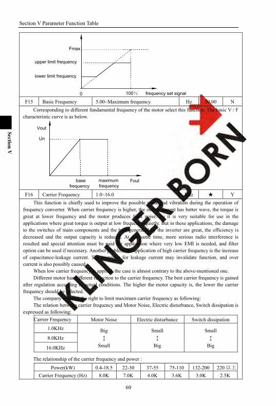
Section V Parameter Function Table
60
Section V
Fmax
0
upper limit frequency
lower limit frequency
frequency set signal100% F15 Basic Frequency 5.00~Maximum frequency Hz 50.00 N
Corresponding to different fundamental frequency of the motor select this function. The basic V / F characteristic curve is as below.
Fout
Un
basefrequency
maximumfrequency
Vout
F16 Carrier Frequency 1.0~16.0 kHz Y
This function is chiefly used to improve the possible noise and vibration during the operation of frequency converter. When carrier frequency is higher, the output current has better wave, the torque is great at lower frequency and the motor produces light noise. So it is very suitable for use in the applications where great torque is output at low frequency quietly. But in these applications, the damage to the switches of main components and the heat generated by the inverter are great, the efficiency is decreased and the output capacity is reduced. At the same time, more serious radio interference is resulted and special attention must be paid for application where very low EMI is needed, and filter option can be used if necessary. Another problem for application of high carrier frequency is the increase of capacitance-leakage current. The protector for leakage current may invalidate function, and over current is also possibly caused.
When low carrier frequency is applied, the case is almost contrary to the above-mentioned one. Different motor has different reflection to the carrier frequency. The best carrier frequency is gained
after regulation according to actual conditions. The higher the motor capacity is, the lower the carrier frequency should be selected.
The company reserves the right to limit maximum carrier frequency as following: The relation between carrier frequency and Motor Noise, Electric disturbance, Switch dissipation is
expressed as following: Carrier Frequency Motor Noise Electric disturbance Switch dissipation
1.0KHz Big
Small
Small
Big
Small
Big 8.0KHz
16.0KHz
The relationship of the carrier frequency and power :
Power(kW) 0.4-18.5 22-30 37-55 75-110 132-200 220 以上 Carrier Frequency (Hz) 8.0K 7.0K 4.0K 3.6K 3.0K 2.5K

Section V Parameter Function Table
61
Section V
Note: Carrier frequency is bigger, the temperatuer of the machine is higher.
F17 Carrier Frequency Adjustment Range
0.0~4.0 kHz 0.0 Y
F18 Carrier Frequency Adjustment Mode
1 bit No automatic adjustment 0
- 00 Y
automatic adjustment Mode
1
10 bit
automatic adjustment, Fixed mode
0
automatic adjustment, random mode
1
F17 Carrier frequency adjustment range 0.0~4.0kHz, Actual Carrier frequency adjustment range 1.0~16.0kHz F18 Carrier frequency adjustment Mode
1 Bit: Carrier frequency automatic adjustment mode 0: No automatic adjustment Carrier frequency according F16 to set . 1: automatic adjustment Mode The carrier frequency automatically adjusts the model 10 can select random mode and fixed pattern.
10 Bit: Stochastic adjustment mode 0: automatic adjustment, Fixed mode Load current>80% Carrier frequency =F16-F17 Load current<60% Carrier frequency =F16+F17 1: automatic adjustment, random mode Load current >80% Carrier frequency = (F16-F17)~F16 Load current <60% Carrier frequency = F16~(F16+F17)
F19 Waveform Generation Mode
Asynchronous space-vector PWM 0
- 0 N Stepless & subsection synchronous space vector PWM
1
two-phase optimization space vector PWM
2
PWM wave produce mode 0: Asynchronous space-vector PWM 1: Stepless & subsection synchronous space vector PWM 2: two-phase optimization space vector PWM
F20 S Curve Start Time At The Acceleration Step
0.0~50.0 % 0.0 Y
F21 S Curve Stop Time At The Acceleration Atep
0.0~50.0 % 0.0 Y
F22 S Curve Start Time At The Deceleration Step
0.0~50.0 % 0.0 Y
F23 S Curve Stop Time At The Deceleration Step
0.0~50.0 % 0.0 Y
1 indicat that the slope of the output frequency from 0 to the max. 2 indicat that the slope of the output frequency at constant segment. 3 indicat that the slope of the output frequency is reduced to 0 from the max. Such as setting the S curve acceleration and deceleration, acceleration and deceleration time from
0Hz to the maximum frequency is calculated as follows: Plus acceleration S characteristic time = F09 * F20 Constant extra acceleration S characteristic time = F09-(F09 * F20 + F09 * F21)
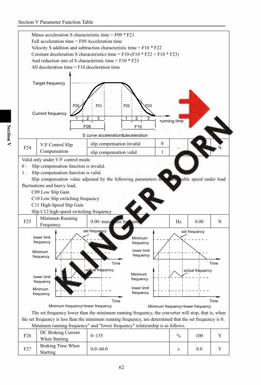
Section V Parameter Function Table
62
Section V
Minus acceleration S characteristic time = F09 * F21 Full acceleration time = F09 Acceleration time Velocity S addition and subtraction characteristic time = F10 * F22 Constant deceleration S characteristics time = F10-(F10 * F22 + F10 * F23) And reduction rate of S characteristic time = F10 * F23 All deceleration time = F10 deceleration time
F20 F21 F22 F23
1 12 3 2 3
F09 F10
Target frequency
running time
Current frequency
S curve acceleration&deceleration
F24 V/F Control Slip Compensation
slip compensation invalid 0 - 0 N
slip compensation valid 1 Valid only under V/F control mode. 0 : Slip compensation function is invalid. 1 : Slip compensation function is valid.
Slip compensation value adjusted by the following parameters to ensure stable speed under load fluctuations and heavy load,
C09 Low Slip Gain C10 Low Slip switching frequency C11 High-Speed Slip Gain Slip C12 high-speed switching frequency
F25 Minimum Running Frequency 0.00~maximum frequency Hz 0.00 N
Minimum frequency<lower frequency
Time
actual frequency
Time Time
Time
lower limitfrequency
set frequency
Minimumfrequency
lower limitfrequency
lower limitfrequency
lower limitfrequency
actual frequency
set frequency
Minimum frequency>lower frequency
Minimumfrequency
Minimumfrequency
Minimumfrequency
The set frequency lower than the minimum running frequency, the converter will stop, that is, when
the set frequency is less than the minimum running frequency, are determined that the set frequency is 0. Minimum running frequency" and "lower frequency" relationship is as follows.
F26 DC Braking Current When Starting
0~135 % 100 Y
F27 Braking Time When Starting
0.0~60.0 s 0.0 Y
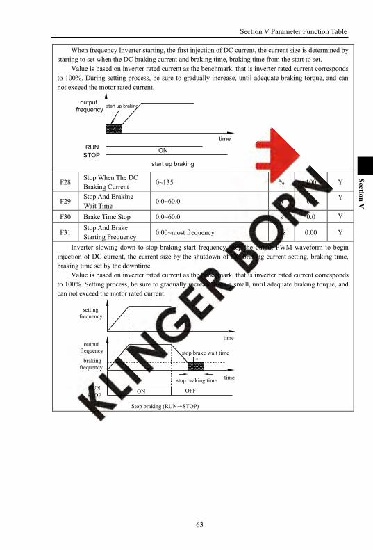
Section V Parameter Function Table
63
Section V
When frequency Inverter starting, the first injection of DC current, the current size is determined by starting to set when the DC braking current and braking time, braking time from the start to set.
Value is based on inverter rated current as the benchmark, that is inverter rated current corresponds to 100%. During setting process, be sure to gradually increase, until adequate braking torque, and can not exceed the motor rated current.
start up braking
RUNSTOP
outputfrequency
start up braking
ON
time
F28 Stop When The DC Braking Current
0~135 % 100 Y
F29 Stop And Braking Wait Time
0.0~60.0 s 0.0 Y
F30 Brake Time Stop 0.0~60.0 s 0.0 Y
F31 Stop And Brake Starting Frequency
0.00~most frequency Hz 0.00 Y
Inverter slowing down to stop braking start frequency, stop the output PWM waveform to begin injection of DC current, the current size by the shutdown of DC braking current setting, braking time, braking time set by the downtime.
Value is based on inverter rated current as the benchmark, that is inverter rated current corresponds to 100%. Setting process, be sure to gradually increase from a small, until adequate braking torque, and can not exceed the motor rated current.
brakingfrequency
time
time
Stop braking (RUN→STOP)
STOPOFF
stop braking timeRUN ON
settingfrequency
outputfrequency stop brake wait time

Section V Parameter Function Table
64
Section V
settingfrequencyforward
reversecommand
FOR REV
stop braking (forward and reverse rotate)
time
time
settingfrequency
outputfrequency
brakingfrequency
stop braking time
stop brake wait time
ON
settingfrequency
outputfrequency
brakingfrequency
RUNSTOP
brakingfrequency
stop braking time time
time
stop braking (run state)
stop brake wait time
F32 Stop Setting Mode Deceleration stop 0
- 0 N Free stop 1
When the frequency inverter receives the "stop" command, it will set the parameters accordingly to this parameter to set the motor stop mode. 0 : deceleration to stop
Mode converter according to parameters set by the deceleration time to set the deceleration mode to slow down to the lowest frequencies to stop.
1 : Free stop mode Inverter receive "stop" command immediately stop output, according to the load inertia, motor free-run to stop.
F33 Jog Acceleration Time 0.0~3200.0 s 1.0 N
F34 Jog Deceleration Time 0.0~3200.0 s 1.0 N
F35 Jog Mode Setting
1 bit
Jog direction: forward 0
- 000 N
Jog direction: reverse 1 Jog direction: direction determined by the main terminal
2
10 bit
Jog end mode: Stop Running 0
Jog end mode:reset to the former state before jog
1
100 bit Jog end and acceleration deceleration time: reset
0

Section V Parameter Function Table
65
Section V
to the set acceleration and deceleration time before jog
Jog end and acceleration deceleration time:save the set acceleration and deceleration time before jog
1
F36 Jog Frequency Setting Lower frequency ~upper frequency Hz 6.00 Y
F34F33running time
Linear Acceleration
Fmax
Jog acceleration/deceleration time configuration defines the same section of acceleration / decele -
ration time. The direction of jog is set by the unit bit of F35,when the Jog command does not contain the dire -
ction of jog, the direction of job will run as to the unit bit designated by F35. It is set to 2, the direction of jog is run by the terminal or current direction.
The running status after jogging is identified by F35. Whether jog acceleration/deceleration time is maintained through the confirmation on hundred bit
of F35 after jogging F37 Skip Frequency1Limit 0.00~Maximum frequency Hz 0.00 Y
F38 Skip Frequency1Upper 0.00~Maximum frequency Hz 0.00 Y
F39 Skip Frequency2Limit 0.00~Maximum frequency Hz 0.00 Y
F40 Skip Frequency2Upper 0.00~Maximum frequency Hz 0.00 Y
F41 Skip Frequency3Limit 0.00~Maximum frequency Hz 0.00 Y
F42 Skip Frequency3Upper 0.00~Maximum frequency Hz 0.00 Y
During running, to skip resonance produced by the immanent resonance point in the machine sys - tems, skip mode can do this.
At most three resonance points could be set to skip.
frequency setting signal
upper skip frequency 3
upper skip frequency 2
upper skip frequency 1
skip frequency 3
skip frequency 2
output frequency
skip frequency 1lower skip frequency 1
lower skip frequency 2
lower skip frequency 3
Upper skip frequency and lower skip frequency define skip frequency range.
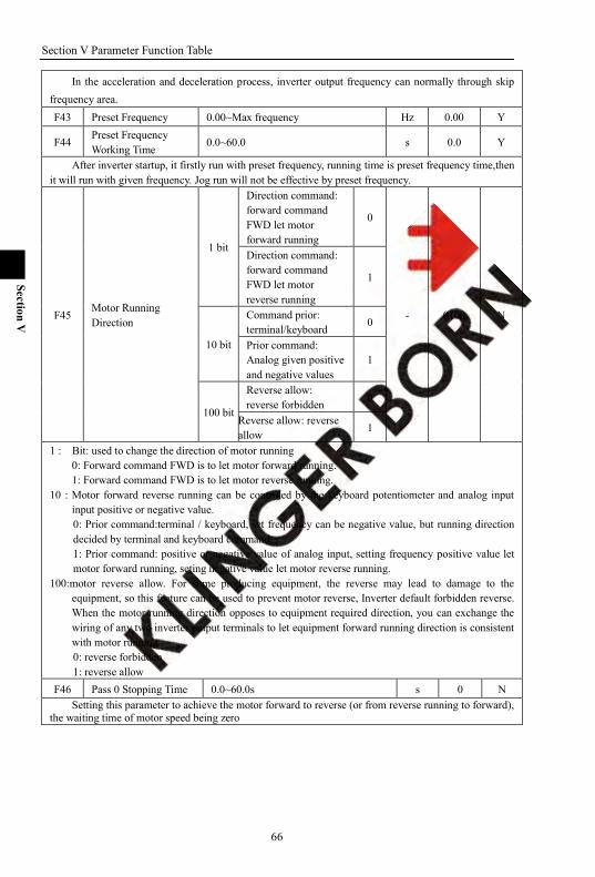
Section V Parameter Function Table
66
Section V
In the acceleration and deceleration process, inverter output frequency can normally through skip frequency area. F43 Preset Frequency 0.00~Max frequency Hz 0.00 Y
F44 Preset Frequency Working Time
0.0~60.0 s 0.0 Y
After inverter startup, it firstly run with preset frequency, running time is preset frequency time,then it will run with given frequency. Jog run will not be effective by preset frequency.
F45 Motor Running Direction
1 bit
Direction command: forward command FWD let motor forward running
0
- 0100 N
Direction command: forward command FWD let motor reverse running
1
10 bit
Command prior: terminal/keyboard 0
Prior command: Analog given positive and negative values
1
100 bit
Reverse allow: reverse forbidden 0
Reverse allow: reverse allow 1
1 : Bit: used to change the direction of motor running 0: Forward command FWD is to let motor forward running. 1: Forward command FWD is to let motor reverse running.
10 : Motor forward reverse running can be controled by the keyboard potentiometer and analog input input positive or negative value. 0: Prior command:terminal / keyboard, set frequency can be negative value, but running direction decided by terminal and keyboard command. 1: Prior command: positive or negative value of analog input, setting frequency positive value let motor forward running, seting negative value let motor reverse running.
100:motor reverse allow. For some producing equipment, the reverse may lead to damage to the equipment, so this feature can be used to prevent motor reverse, Inverter default forbidden reverse. When the motor running direction opposes to equipment required direction, you can exchange the wiring of any two inverter output terminals to let equipment forward running direction is consistent with motor running. 0: reverse forbidden 1: reverse allow
F46 Pass 0 Stopping Time 0.0~60.0s s 0 N Setting this parameter to achieve the motor forward to reverse (or from reverse running to forward),
the waiting time of motor speed being zero
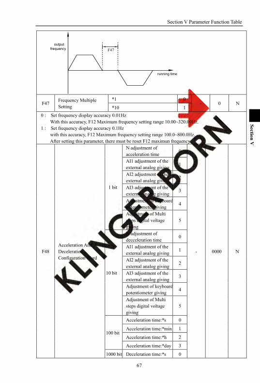
Section V Parameter Function Table
67
Section V
F47output
frequency
running time
F47 Frequency Multiple Setting
*1 0 - 0 N
*10 1 0 : Set frequency display accuracy 0.01Hz
With this accuracy, F12 Maximum frequency setting range 10.00~320.00Hz. 1 : Set frequency display accuracy 0.1Hz
with this accuracy, F12 Maximum frequency setting range 100.0~800.0Hz. After setting this parameter, there must be reset F12 maximun frequency.
F48 Acceleration And Deceleration Configuration Word
1 bit
N adjustment of acceleration time
0
- 0000 N
AI1 adjustment of the external analog giving 1
AI2 adjustment of the external analog giving 2
AI3 adjustment of the external analog giving
3
Adjustment of keyboard potentiometer giving
4
Adjustment of Multi steps digital voltage giving
5
10 bit
N adjustment of decceleration time
0
AI1 adjustment of the external analog giving
1
AI2 adjustment of the external analog giving
2
AI3 adjustment of the external analog giving 3
Adjustment of keyboard potentiometer giving 4
Adjustment of Multi steps digital voltage giving
5
100 bit
Acceleration time:*s 0
Acceleration time:*min 1
Acceleration time:*h 2
Acceleration time:*day 3
1000 bit Deceleration time:*s 0
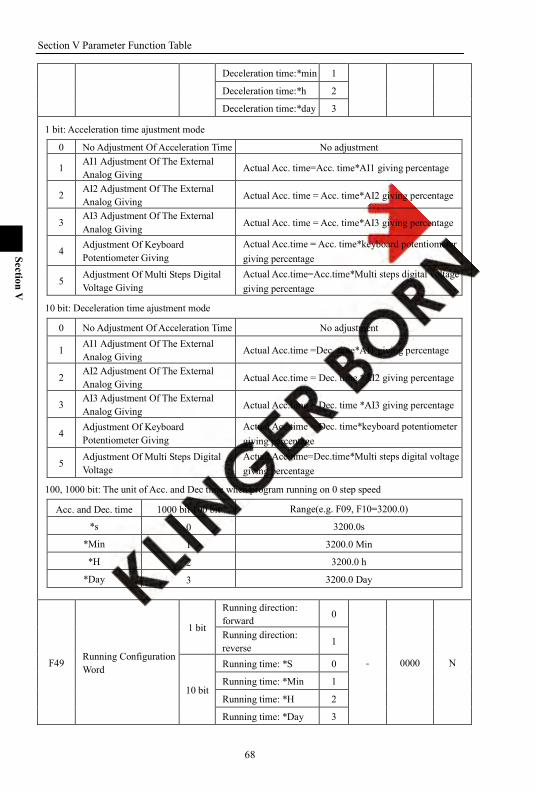
Section V Parameter Function Table
68
Section V
Deceleration time:*min 1
Deceleration time:*h 2
Deceleration time:*day 3
1 bit: Acceleration time ajustment mode
0 No Adjustment Of Acceleration Time No adjustment
1 AI1 Adjustment Of The External Analog Giving
Actual Acc. time=Acc. time*AI1 giving percentage
2 AI2 Adjustment Of The External Analog Giving Actual Acc. time = Acc. time*AI2 giving percentage
3 AI3 Adjustment Of The External Analog Giving Actual Acc. time = Acc. time*AI3 giving percentage
4 Adjustment Of Keyboard Potentiometer Giving
Actual Acc.time = Acc. time*keyboard potentiometer giving percentage
5 Adjustment Of Multi Steps Digital Voltage Giving
Actual Acc.time=Acc.time*Multi steps digital voltage giving percentage
10 bit: Deceleration time ajustment mode
0 No Adjustment Of Acceleration Time No adjustment
1 AI1 Adjustment Of The External Analog Giving
Actual Acc.time =Dec. time*AI1 giving percentage
2 AI2 Adjustment Of The External Analog Giving Actual Acc.time = Dec. time *AI2 giving percentage
3 AI3 Adjustment Of The External Analog Giving Actual Acc.time = Dec. time *AI3 giving percentage
4 Adjustment Of Keyboard Potentiometer Giving
Actual Acc.time = Dec. time*keyboard potentiometer giving percentage
5 Adjustment Of Multi Steps Digital Voltage
Actual Acc.time=Dec.time*Multi steps digital voltage giving percentage
100, 1000 bit: The unit of Acc. and Dec time when program running on 0 step speed
Acc. and Dec. time 1000 bit 100 bit Range(e.g. F09, F10=3200.0)
*s 0 3200.0s
*Min 1 3200.0 Min
*H 2 3200.0 h
*Day 3 3200.0 Day
F49 Running Configuration Word
1 bit
Running direction: forward
0
- 0000 N
Running direction: reverse
1
10 bit
Running time: *S 0
Running time: *Min 1
Running time: *H 2
Running time: *Day 3
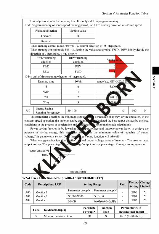
Section V Parameter Function Table
69
Section V
Unit adjustment of actual running time.It is only valid on program running. 1 bit: Program running on multi-speed running period, Set bit to running direction of ―0‖step speed.
Running driection Setting value
Forward 0
Reverse 1 When running control mode F05=0/1/2, control direction of ―0‖ step speed. When running control mode F05=3, Setting the value and terminal FWD / REV jointly decide the direction of 0 step speed, FWD priority.
FWD=1running direction
REV=1running direction Setting value
FWD REV 0
REW FWD 1
10 bit: unit of time running when on ―0‖ step speed. Running time 10 bit range(e.g. H18~H25=3200.0)
*S 0 3200.0s
*Min 1 3200.0Min
*H 2 3200.0H
*Day 3 3200.0 Day
F50 Energy Saving Running Percentage 30~100 % 100 N
This parameter describes the minimum output voltage percentage of energy-saving operation. In the constant speed operation, the inverter can be automatically calculated the best output voltage by the load conditions.In the process of acceleration and deceleration is not to make such calculations.
Power-saving function is by lowering the output voltage and improve power factor to achieve the purpose of saving energy, this parameter determines the minimum value of reducing of output voltage;This parameter is set to 100%, then energy-saving function will take off.
When energy-saving function in effect, Actual output voltage value of inverter= The inverter rated output voltage*The percentage of output voltage*output voltage percentage of energy saving operation.
frequency (Hz)
output voltatge (V)
100%
75%
5-2-4. User Function Group:A00-A55(0x0100-0x0137)
Code Description / LCD Setting Range Unit Factory Setting
Change Limited
A00 A01 A02
Monitor 1 Monitor 2 Monitor 3
Parameter group N: Parameter group N: - - -
0B00 0B01 0B02
Y Y Y
X1000/X100 X10/ bit
00~0B 0~63(0x00~0x3F)
Code Keyboard display Parameter group N
Function spec
Parameter N(16 Hexadecimal Input)
S Monitor Function Group 0B S 0~16 (0x00~0x10)
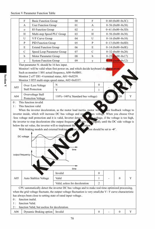
Section V Parameter Function Table
70
Section V
F Basic Function Group 00 F 0~60 (0x00~0x3C) A User Function Group 01 A 0~56 (0x00~0x38) o IO Function Group 02 o 0~61 (0x00~0x3D) H Multi-step Speed PLC Group 03 H 0~56 (0x00~0x38) U V/F Curve Group 04 U 0~16 (0x00~0x10) P PID Function Group 05 P 0~13 (0x00~0x0D) E Extend Function Group 06 E 0~14 (0x00~0x0E) C Speed Loop Parameter Group 07 C 0~32 (0x00~0x20) b Motor Parameter Group 08 b 0~23 (0x00~0x17) y System Function Group 09 y 0~18 (0x00~0x12)
That parameter N. should be 16 hex input. Monitor1 will be valid when first power on, and which decide keyboard display content. Such as:monitor 1 S01 actual frequency, A00=0x0B01. Monitor 2 o57 DI1~4 terminal status, A01=0x0239. Monitor 3 H55 multi-steps speed status, A02=0x0337.
A03 Over /Less Voltage Stall Protection
N 0 - 1 Y
Y 1
A04 Overvoltage Stall Protection Voltage
110%~140%( Standard bus voltage) % 120 Y
0 : This function invalid 1 : This function valid
When the inverter deceleration, as the motor load inertia, motor will produce feedback voltage to inverter inside, which will increase DC bus voltage and surpass max voltage. When you choose Over /less voltage stall protection and it is valid, Inverter detects DC side voltage, if the voltage is too high, the inverter to stop deceleration (the output frequency remains unchanged), until the DC side voltage is below the set value, the inverter will re-implement the deceleration
With braking models and external braking resistor, this function should be set to ―0‖.
time
time
output frequency
DC voltage
A05 Auto Stablize Voltage
Invalid 0
- 0 Y Valid 1
Valid, usless for deceleration 2 CPU automatically detect the inverter DC bus voltage and to make real-time optimized processing,
when the grid voltage fluctuate, the output voltage fluctuation is very small,the V / F curve characteristic has always been close to setting state of rated input voltage.. 0 : function inalid. 1 : function Valid. 2 : function Valid, but useless for deceleration. A06 Dynamic Braking option Invalid 0 - 0 Y
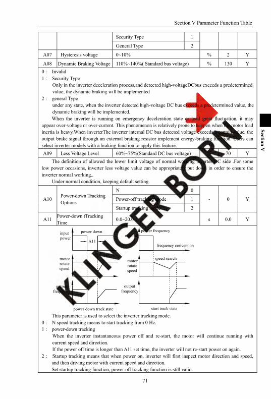
Section V Parameter Function Table
71
Section V
Security Type 1
General Type 2
A07 Hysteresis voltage 0~10% % 2 Y
A08 Dynamic Braking Voltage 110%~140%( Standard bus voltage) % 130 Y 0 : Invalid 1 : Security Type
Only in the inverter deceleration process,and detected high-voltageDCbus exceeds a predetermined value, the dynamic braking will be implemented
2 : general Type under any state, when the inverter detected high-voltage DC bus exceeds a predetermined value, the dynamic braking will be implemented. When the inverter is running on emergency deceleration state or load great fluctuation, it may
appear over-voltage or over-current. This phenomenon is relatively prone to happen when the motor load inertia is heavy.When inverterThe inverter internal DC bus detected voltage exceeds a certain value, the output brake signal through an external braking resistor implement energy-braking function. Users can select inverter models with a braking function to apply this feature. A09 Less Voltage Level 60%~75%(Standard DC bus voltage) % 70 Y
The definition of allowed the lower limit voltage of normal working inverter DC side .For some low power occasions, inverter less voltage value can be appropriately put down in order to ensure the inverter normal working..
Under normal condition, keeping default setting.
A10 Power-down Tracking Options
N 0
- 0 Y Power-off tracking mode 1
Startup tracking mode 2
A11 Power-down tTracking Time
0.0~20.0 s 0.0 Y
start track statepower down track state
speed search
frequency conversion
power frequencypower downcontrol
motor rotate speed
output frequency
output frequency
motor rotate speed
input power
A11
This parameter is used to select the inverter tracking mode.
0 : N speed tracking means to start tracking from 0 Hz. 1 : power-down tracking
When the inverter instantaneous power off and re-start, the motor will continue running with current speed and direction. If the power off time is longer than A11 set time, the inverter will not re-start power on again.
2 : Startup tracking means that when power on, inverter will first inspect motor direction and speed, and then driving motor with current speed and direction. Set startup tracking function, power off tracking function is still valid.

Section V Parameter Function Table
72
Section V
A12 Power Down Frequency Drop Point
65~100%(standard DC bus voltage) % 75 Y
A13 Power Down Frequency Drop Time
0.1~3200.0 s 5.0 Y
Correctly setting this parameter can let inverter does not less voltage stop in case of instantaneous power off.
When the DC bus voltage drop to frequency drop point A12 set, inverter will decelerate according to deceleration time A13 set and stop outputting power to load. Meanwhile, inverter will use load feedback energy to compensate DC bus voltage dropping and keep inverter working in short time.
Power down frequency drop time actually is deceleration time of frequency dropping after power off.
If this value set is too large, the load feedback energy is small, then inverter can not compensate for voltage dropping in DC.
if this value set is too small and there is large energy feedback from load, the excessive energy compensation may cause inverter over-voltage fault.
Set A12 100% to cancel power off frequency dropping function.
A14 Current Limit N 0
- 0 Y Y 1
A15 Limit Fall Time 0.1~3200.0 s 10.0 Y
A16 Limit Deceleration Protection Point 10~250 % Y
A17 Limit Fix-speed Protection Point
10~250 % Y
Series Current limitaiton% Corresponding parameter
F 120 A17 130 A16
G 150 A17 170 A16
M、T、Z 170 A17 190 A16
H 250 A17 270 A16
Current limitation function can effectively restrain over-current caused by motor load fluctuation in the process of acceleration and deceleration or constant speed operation.
This function will be good effect for V/F control mode. Under protection of current lost- speed state, the motor speed will drop. so it is not adapted by
systme which is not allowed to automatically drop speed. In operation process, when the motor current surpass value A16 set, motor will decelerate
according to deceleration time A15 set until current below value A16 set. In operation process, when the motor surpass value A17 set, motor will run with this speed until
current below value A17 set. Deceleration current limitation is prior of constant speed limitation.
A18 Output Phase Lose Protection
N protection of phase lost 0
- 0 Y Warning and constant running 1
Warning and deceleration 2
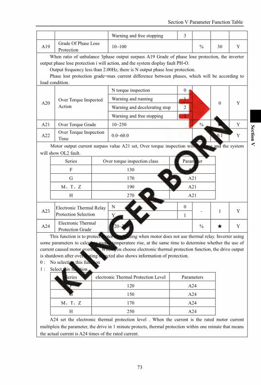
Section V Parameter Function Table
73
Section V
Warning and free stopping 3
A19 Grade Of Phase Lose Protection
10~100 % 30 Y
When ratio of unbalance 3phase output surpass A19 Grade of phase lose protection, the inverter output phase lose protection i will action, and the system display fault PH-O.
Output frequency less than 2.00Hz, there is N output phase lose protection. Phase lost protection grade=max current difference between phases, which will be according to
load condition.
A20 Over Torque Inspected Action
N torque inspection 0
- 0 Y Warning and running 1
Warning and decelerating stop 2
Warning and free stopping 3
A21 Over Torque Grade 10~250 % Y
A22 Over Torque Inspection Time 0.0~60.0 s 0.1 Y
Motor output current surpass value A21 set, Over torque inspection will be force and the system will show OL2 fault.
Series Over torque inspection class Parameter
F 130 A21
G 170 A21
M、T、Z 190 A21
H 270 A21
A23 Electronic Thermal Relay Protection Selection
N 0 - 1 Y
Y 1
A24 Electronic Thermal Protection Grade
120~250 % Y
This function is to protect motor overheating when motor does not use thermal relay. Inverter using some parameters to calculate motor temperature rise, at the same time to determine whether the use of current caused motor overheat. When you choose electronic thermal protection function, the drive output is shutdown after overheating detected also shows information of protection. 0 : No selecting this function 1 : Select this function.
Series electronic Thermal Protection Level Parameters
F 120 A24
G 150 A24
M、T、Z 170 A24
H 250 A24 A24 set the electronic thermal protection level . When the current is the rated motor current
multipleis the parameter, the drive in 1 minute protects, thermal protection within one minute that means the actual current is A24 times of the rated current.
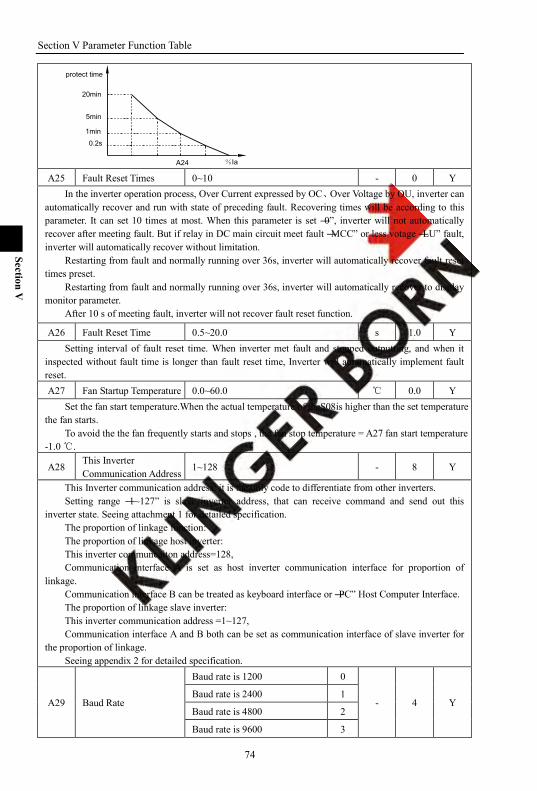
Section V Parameter Function Table
74
Section V
20min
0.2s
1min
5min
protect time
%IaA24 A25 Fault Reset Times 0~10 - 0 Y
In the inverter operation process, Over Current expressed by OC、Over Voltage by OU, inverter can automatically recover and run with state of preceding fault. Recovering times will be according to this parameter. It can set 10 times at most. When this parameter is set ―0‖, inverter will not automatically recover after meeting fault. But if relay in DC main circuit meet fault ―MCC‖ or less votage ―LU‖ fault, inverter will automatically recover without limitation.
Restarting from fault and normally running over 36s, inverter will automatically recover fault reset times preset.
Restarting from fault and normally running over 36s, inverter will automatically recover to display monitor parameter.
After 10 s of meeting fault, inverter will not recover fault reset function.
A26 Fault Reset Time 0.5~20.0 s 1.0 Y Setting interval of fault reset time. When inverter met fault and stopped outputting, and when it
inspected without fault time is longer than fault reset time, Inverter will automatically implement fault reset. A27 Fan Startup Temperature 0.0~60.0 0.0 Y
Set the fan start temperature.When the actual temperature of theS08is higher than the set temperature the fan starts.
To avoid the the fan frequently starts and stops , the fan stop temperature = A27 fan start temperature -1.0 .
A28 This Inverter Communication Address
1~128 - 8 Y
This Inverter communication address: it is the only code to differentiate from other inverters. Setting range ―1~127‖ is slave inverter address, that can receive command and send out this
inverter state. Seeing attachment 1 for detailed specification. The proportion of linkage function: The proportion of linkage host inverter: This inverter communcaiton address=128, Communication interface A is set as host inverter communication interface for proportion of
linkage. Communication interface B can be treated as keyboard interface or ―PC‖ Host Computer Interface. The proportion of linkage slave inverter: This inverter communication address =1~127, Communication interface A and B both can be set as communication interface of slave inverter for
the proportion of linkage. Seeing appendix 2 for detailed specification.
A29 Baud Rate
Baud rate is 1200 0
- 4 Y Baud rate is 2400 1
Baud rate is 4800 2
Baud rate is 9600 3
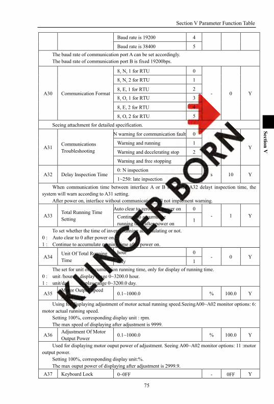
Section V Parameter Function Table
75
Section V
Baud rate is 19200 4
Baud rate is 38400 5 The baud rate of communication port A can be set accordingly. The baud rate of communication port B is fixed 19200bps.
A30 Communication Format
8, N, 1 for RTU 0
- 0 Y
8, N, 2 for RTU 1
8, E, 1 for RTU 2
8, O, 1 for RTU 3
8, E, 2 for RTU 4
8, O, 2 for RTU 5
Seeing attachment for detailed specification.
A31 Communications Troubleshooting
N warning for communication fault 0
- 0 Y Warning and running 1
Warning and decelerating stop 2
Warning and free stopping 3
A32 Delay Inspection Time 0: N inspection
s 10 Y 1~250: late inpsection
When communication time between interface A or B surpassed A32 delayt inspection time, the system will warn according to A31 setting.
After power on, interface without communication will not implement warning.
A33 Total Running Time Setting
Auto clear to zero after power on 0 - 1 Y Continue to accumulate
running time after power on 1
To set whether the time of inverer running accumulating or not. 0 : Auto clear to 0 after power on. 1 : Continue to accumulate running time after power on.
A34 Unit Of Total Running Time
hour 0 - 0 Y
Day 1 The set for unit of accumulation running time, only for display of running time.
0 : unit /hour display range 0~3200.0 hour. 1 : unit/day display range 0~3200.0 day.
A35 Motor Output Speed Adjustment
0.1~1000.0 % 100.0 Y
Using for displaying adjustment of motor actual running speed.SeeingA00~A02 monitor options: 6: motor actual running speed.
Setting 100%, corresponding display unit : rpm. The max speed of displaying after adjustment is 9999.
A36 Adjustment Of Motor Output Power
0.1~1000.0 % 100.0 Y
Used for displaying motor ouput power of adjustment. Seeing A00~A02 monitor options: 11 :motor output power.
Setting 100%, corresponding display unit:%. The max ouput power of displaying after adjustment is 2999.9.
A37 Keyboard Lock 0~0FF - 0FF Y
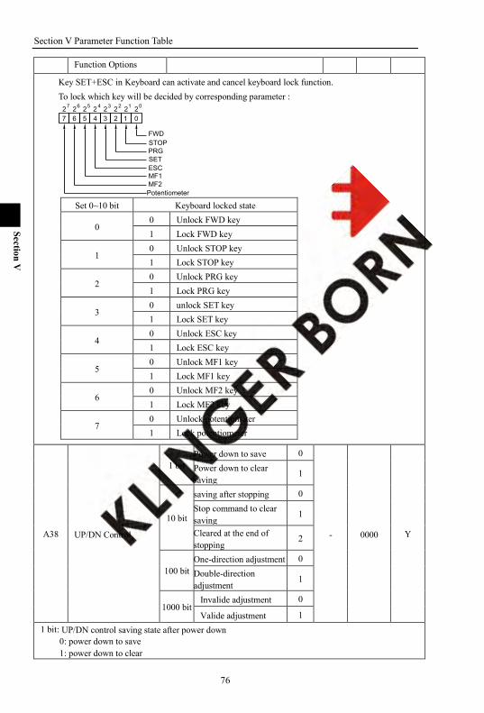
Section V Parameter Function Table
76
Section V
Function Options
Key SET+ESC in Keyboard can activate and cancel keyboard lock function. To lock which key will be decided by corresponding parameter :
Potentiometer
7 6 5 4 3 2 1 02 2 2 2 2 2 2 201234567
FWDSTOPPRGSETESCMF1MF2
Set 0~10 bit Keyboard locked state
0 0 Unlock FWD key 1 Lock FWD key
1 0 Unlock STOP key 1 Lock STOP key
2 0 Unlock PRG key 1 Lock PRG key
3 0 unlock SET key 1 Lock SET key
4 0 Unlock ESC key 1 Lock ESC key
5 0 Unlock MF1 key 1 Lock MF1 key
6 0 Unlock MF2 key 1 Lock MF2 key
7 0 Unlock potentiometer 1 Lock potentiometer
A38 UP/DN Control
1 bit Power down to save 0
- 0000 Y
Power down to clear saving
1
10 bit
saving after stopping 0 Stop command to clear saving 1
Cleared at the end of stopping
2
100 bit One-direction adjustment 0 Double-direction adjustment
1
1000 bit Invalide adjustment 0
Valide adjustment 1 1 bit: UP/DN control saving state after power down
0: power down to save 1: power down to clear

Section V Parameter Function Table
77
Section V
10 bit: UP/DN control saving after stopping 0: Keeping afer stopping 1: Stop command to clear saving 2: Cleared at the end of stopping
100 bit: UP/DN control direction of adjustment. 0: one direction adjustment, it is one direction adjustment within 0~max frequency range. 1: double direction adjusment, it is FEW and REW adjustment within 0~max frequency range.
1000 bit: UP/DN control validity of adjustment. 0: UP/DN invalid ajustment 1 : UP/DN valid adjustment
A39 UP/DN Time
1 bit UP fix speed 0
- 0000 N
UP fix times 1
10 bit DN fix speed 0
DN fix times 1
100 bit
UP N adjustmentof speed ratio 0
AI1 adjustment of the external analog giving
1
AI2 adjustment of the external analog giving
2
AI3 adjustment of the external analog giving
3
adjustment of Potentiometer giving
4
Adjustment of multi -steps digital voltage 5
1000 bit
DN N adjustmentof speed ratio 0
AI1 adjustment of the external analog giving
1
AI2 adjustment of the external analog giving
2
AI3 adjustment of the external analog giving
3
adjustment of Potentiometer giving
4
Adjustment of multi -steps digital voltage 5
1 bit: UP acceleration mode 0: fix speed acceleration, according to A41 fix speed: To increase frequency every 200ms. 1: fix times acceleration, according to fix times: To increase frequency every triggering.
10 bit: DN deceleration mode 0: fix speed deceleration, according to A42 fix speed: To reduce frequency every 200ms. 1: fix times deceleration, according to A42 fix times: To reduce frequency every triggering.
100 bit: UP adjustment mode of adjusting speed ratio
0 UP N Adjustment Of Speed Ratio
N adjustment
1 AI1 Adjustment Of The Actual UP adjustment ratio= percentage given by A41*AI1

Section V Parameter Function Table
78
Section V
External Analog Giving
2 AI2 Adjustment Of The External Analog Giving Actua UP adjustment ratio= percentage given by A41*AI2
3 AI3 Adjustment Of The External Analog Giving Actual UP adjustment ratio= percentage given by A41*AI3
4 Adjustment Of Potentiometer Giving
Actual UP adjustment ratio= percentage given by A41* potentiometer
5 Adjustment Of Multi-steps Digital Voltage
Actual UP adjustment ratio=percentage given by A41* multi-steps digital voltage
1000 bit: DN adjustment mode of adjusting speed ratio
0 N Adjustment Of Acceleration Time N adjustment
1 AI1 Adjustment Of The External Analog Giving
Actual DN adjustment ratio =percentage given by A42*AI1
2 AI2 Adjustment Of The External Analog Giving Actual DN adjustment ratio =percentage given by A42*AI2
3 AI3 Adjustment Of The External Analog Giving Actual DN adjustment ratio=percentage given by A42*AI3.
4 Adjustment Of Potentiometer Giving
Actual DN adjustment ratio=percentage given by A42*potentiometer
5 Adjustment Of Multi-steps Digital Voltage
Actual DN adjustment ratio=percentage given by A42*multi-steps digital voltge.
A40 UP/DN Adjustment Value -300.00~300.00 - 0.00 N
Frequency after adjustment=set frequency+UP/DN adjustment value.
A41 UP Adjustment Ratio 0.01~20.00 Hz 0.01 Y Fix speed: To increase frequency every 200ms. Fix times: To increase frequency every triggering.
A42 DN Adjustment Ratio 0.01~20.00 Hz 0.01 Y Fix speed: To reduce frequency every 200ms. Fix times: To reduce frequency every triggering.
A43A44
The Definition Of Multifunction Keys MF1 And MF2
MF is defined as adding function key
0
- -
0 1
Y Y
MF is definded as reducing function key 1
MF is defined as free stopping key 2
MF is defined as FWD running key 3
MF is defined as REV running key 4 MF is defined as forward JOG function key. 5
MF is defined as reverse JOG function key.
6
MF is defined as JOG function key. 7
MF is defined as UP function key 8
MF is defined as Down function 9
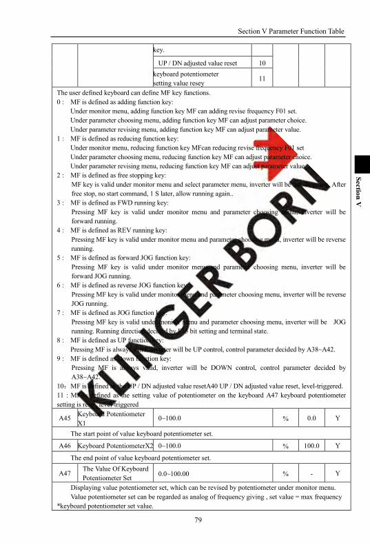
Section V Parameter Function Table
79
Section V
key.
UP / DN adjusted value reset 10 keyboard potentiometer setting value resey
11
The user defined keyboard can define MF key functions. 0 : MF is defined as adding function key:
Under monitor menu, adding function key MF can adding revise frequency F01 set. Under parameter choosing menu, adding function key MF can adjust parameter choice. Under parameter revising menu, adding function key MF can adjust parameter value.
1 : MF is defined as reducing function key: Under monitor menu, reducing function key MFcan reducing revise frequency F01 set Under parameter choosing menu, reducing function key MF can adjust parameter choice. Under parameter revising menu, reducing function key MF can adjust parameter value.
2 : MF is defined as free stopping key: MF key is valid under monitor menu and select parameter menu, inverter will be free stopping. After free stop, no start command, 1 S later, allow running again..
3 : MF is defined as FWD running key: Pressing MF key is valid under monitor menu and parameter choosing menu, inverter will be forward running.
4 : MF is defined as REV running key: Pressing MF key is valid under monitor menu and parameter choosing menu, inverter will be reverse running.
5 : MF is defined as forward JOG function key: Pressing MF key is valid under monitor menu and parameter choosing menu, inverter will be forward JOG running.
6 : MF is defined as reverse JOG function key: Pressing MF key is valid under monitor menu and parameter choosing menu, inverter will be reverse JOG running.
7 : MF is defined as JOG function key: Pressing MF key is valid under monitor menu and parameter choosing menu, inverter will be JOG running. Running direction decided by F35 bit setting and terminal state.
8 : MF is defined as UP function key: Pressing MF is always valid, inverter will be UP control, control parameter decided by A38~A42.
9 : MF is defined as Down function key: Pressing MF is always valid, inverter will be DOWN control, control parameter decided by A38~A42.
10:MF is defined as the UP / DN adjusted value resetA40 UP / DN adjusted value reset, level-triggered. 11 : MF is defined as the setting value of potentiometer on the keyboard A47 keyboard potentiometer setting is reset, level-triggered
A45 Keyboard Potentiometer X1
0~100.0 % 0.0 Y
The start point of value keyboard potentiometer set.
A46 Keyboard PotentiometerX2 0~100.0 % 100.0 Y
The end point of value keyboard potentiometer set.
A47 The Value Of Keyboard Potentiometer Set 0.0~100.00 % - Y
Displaying value potentiometer set, which can be revised by potentiometer under monitor menu. Value potentiometer set can be regarded as analog of frequency giving , set value = max frequency
*keyboard potentiometer set value.
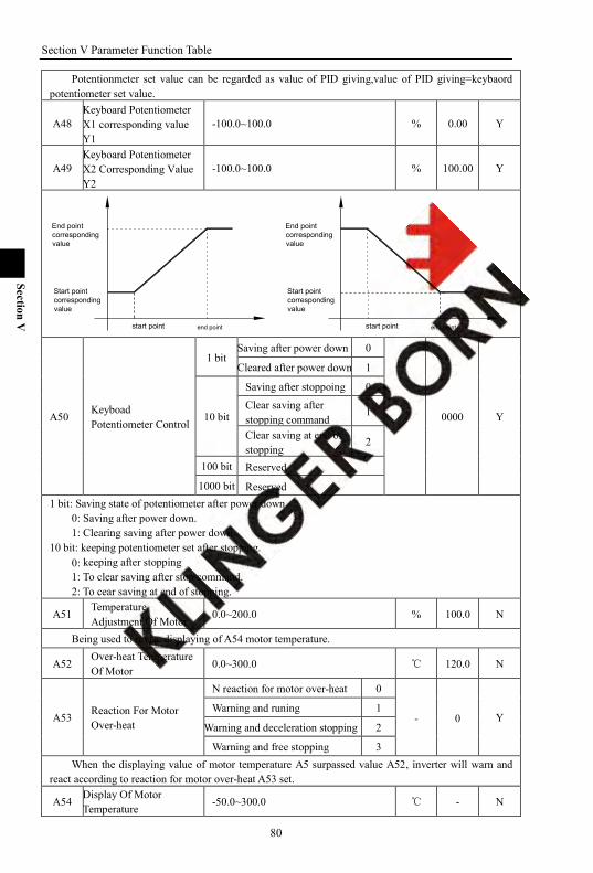
Section V Parameter Function Table
80
Section V
Potentionmeter set value can be regarded as value of PID giving,value of PID giving=keybaord potentiometer set value.
A48 Keyboard Potentiometer X1 corresponding value Y1
-100.0~100.0 % 0.00 Y
A49 Keyboard Potentiometer X2 Corresponding Value Y2
-100.0~100.0 % 100.00 Y
end pointstart point
Start point corresponding value
End point corresponding value
end pointstart point
Start point corresponding value
End point corresponding value
A50 Keyboad Potentiometer Control
1 bit Saving after power down 0
- 0000 Y
Cleared after power down 1
10 bit
Saving after stoppoing 0 Clear saving after stopping command
1
Clear saving at end of stopping
2
100 bit Reserved
1000 bit Reserved 1 bit: Saving state of potentiometer after power down.
0: Saving after power down. 1: Clearing saving after power down.
10 bit: keeping potentiometer set after stopping. 0: keeping after stopping 1: To clear saving after stop command. 2: To cear saving at end of stopping.
A51 Temperature Adjustment Of Motor
0.0~200.0 % 100.0 N
Being used to revise displaying of A54 motor temperature.
A52 Over-heat Temperature Of Motor
0.0~300.0 120.0 N
A53 Reaction For Motor Over-heat
N reaction for motor over-heat 0
- 0 Y Warning and runing 1
Warning and deceleration stopping 2
Warning and free stopping 3 When the displaying value of motor temperature A5 surpassed value A52, inverter will warn and
react according to reaction for motor over-heat A53 set.
A54 Display Of Motor Temperature
-50.0~300.0 - N
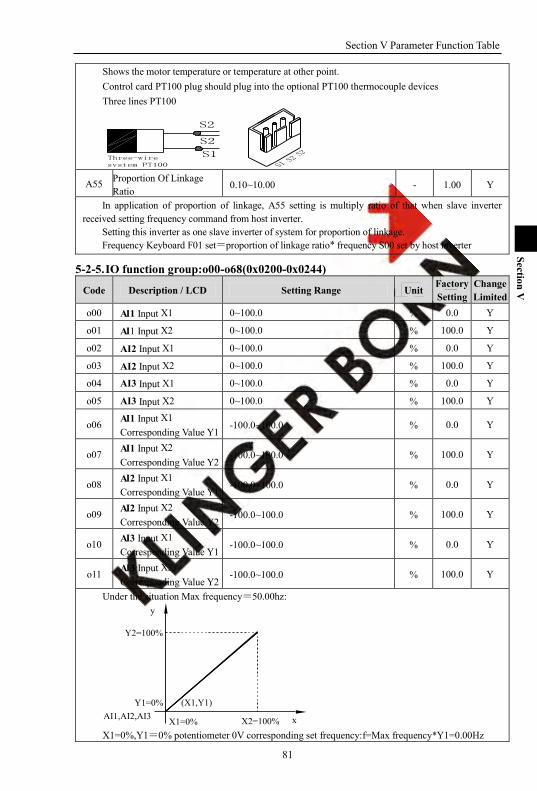
Section V Parameter Function Table
81
Section V
Shows the motor temperature or temperature at other point. Control card PT100 plug should plug into the optional PT100 thermocouple devices Three lines PT100
A55 Proportion Of Linkage Ratio 0.10~10.00 - 1.00 Y
In application of proportion of linkage, A55 setting is multiply ratio of that when slave inverter received setting frequency command from host inverter.
Setting this inverter as one slave inverter of system for proportion of linkage. Frequency Keyboard F01 set=proportion of linkage ratio* frequency S00 set by host inverter
5-2-5. IO function group:o00-o68(0x0200-0x0244)
Code Description / LCD Setting Range Unit Factory Setting
Change Limited
o00 AI1 Input X1 0~100.0 % 0.0 Y
o01 AI1 Input X2 0~100.0 % 100.0 Y
o02 AI2 Input X1 0~100.0 % 0.0 Y
o03 AI2 Input X2 0~100.0 % 100.0 Y
o04 AI3 Input X1 0~100.0 % 0.0 Y
o05 AI3 Input X2 0~100.0 % 100.0 Y
o06 AI1 Input X1 Corresponding Value Y1
-100.0~100.0 % 0.0 Y
o07 AI1 Input X2 Corresponding Value Y2
-100.0~100.0 % 100.0 Y
o08 AI2 Input X1 Corresponding Value Y1
-100.0~100.0 % 0.0 Y
o09 AI2 Input X2 Corresponding Value Y2
-100.0~100.0 % 100.0 Y
o10 AI3 Input X1 Corresponding Value Y1
-100.0~100.0 % 0.0 Y
o11 AI3 Input X2 Corresponding Value Y2
-100.0~100.0 % 100.0 Y
Under the situation Max frequency=50.00hz:
Y2=100%
X2=100%X1=0%
Y1=0%AI1,AI2,AI3 x
y
(X1,Y1)
X1=0%,Y1=0% potentiometer 0V corresponding set frequency:f=Max frequency*Y1=0.00Hz

Section V Parameter Function Table
82
Section V
X2=100%,Y2=100% potentiometer10Vcorresponding set frequency:f=Maxfrequency*Y2=50.00Hz y
xAI1,AI2,AI3Y1=0%
X1=20%
X2=50%
100%
Y2=50%(X2,Y2)
80% 100%10V
(X1,Y1)
X1=20%, Y1=0% potentiometer 2V corresponding set frequency: f=Max frequency*Y1=0.00Hz X2=50%, Y2=50% potentiometer 5V corresponding set frequency: f=Max frequency*Y2=25.00Hz
10V
100%
80%
(X2,Y2)Y2=50%
100%
X2=50%X1=0%
(X1,Y1)
AI1,AI2,AI3 x
y
Y1=20%
X1=0% , Y1=20% potentiometer 0V corresponding set value: f=Max frequency*Y1=10.00Hz X2=50%, Y2=50% potentiometer 5V corresponding set value: f=Max frequency*Y2=25.00Hz
y
xAI1,AI2,AI3
Y1=-100%X1=0%
X2=100%
100%Y2=100%
(X2,Y2)
100%10V
(X1,Y1)
5V50%
X1=0%,Y1=-100% potentiometer 0V corresponding set frequency:f=Max frequency*Y1=-50.00Hz X2=100%,Y2=100%potentiometer 10V correspond set frequency:f=maximum frequency*Y2=50.00Hz Skipping thread of AI1, AI2, AI3 respectively are JP3/JP5, JP6, JP7, seeing the following detailed
specification:
o12 AI1 Input Filter Time 0.00~2.00 s 0.10 Y
o13 AI2 Input Filter Time 0.00~2.00 s 0.10 Y

Section V Parameter Function Table
83
Section V
o14 AI3 Input Filter Time 0.00~2.00 s 0.10 Y Filter time constant of analog signal input, that is 0.00~2.00s.If time parameter is set too long, the
changement of setting frequency will be stable, but responsing speed will be slow;If time parameter is set too short, the changement of setting frequency will not be stable, but responsing speed will be quick.
o15 o16
DA1 Output Terminal DA2 Output Terminal
N reaction 0
- -
- -
Y Y
Setting frequency 1
Actual frequency 2
Actual current 3
Output voltage 4
DC bus voltge 5
IGBT temperature 6
Output power 7
Output RPM 8
Actual value of torque 9
o17 DA1 Adjustment Of Lower Limit Output
0.0~100.0 % 0.0 Y
o18 DA1 Adjustment Of Upper Limit Of Output 0.0~100.0 % 100.0 Y
o19 DA2 Adjustment Of Lower Limit Output 0.0~100.0 % 0.0 Y
o20 DA2 Adjustment Of Upper Limit Output 0.0~100.0 % 100.0 Y
Output Content Setting Value Giving Output Singla Range
N Reaction 0 N output
Setting Frequency 1 0~Max frequency
Actual Frequency 2 0~Max frequency
Actual Current 3 0~200%, corresponding parameter: S03 percentage of output curent
Output Voltage 4 0~200%, corresponding parameter: b02、b15 rate voltage of motor
DC Bus Voltage 5 0~1000VDC, DC voltage
IGBT Temperature 6 0~100.0
Output Power 7 0~200%
Output RPM 8 0~Max RPM Actual Value Of Torque 9 0~200% torque
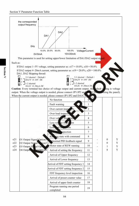
Section V Parameter Function Table
84
Section V
10V/20mA10.0% 20.0%
the correspondedoutput frequency
0V/0mA50.0% 100.0%
0Hz
Voltage/Current
DA1DA2
This parameter is used for setting upper/lower limitation of DA1/DA2 output signal.
Such as: If DA1 output 1~5V voltage, setting parameter as: o17=10.0%, o18=50.0% If DA2 output 4~20mA current, setting parameter as: o19=20.0%, o20=100.0% DA1, DA2 Skipping thread:
Caution: Every terminal has choice of voltage output and current output, the default setting is voltage output. When the voltage output is needed, please connect JP1/JP2 and DA1V/DA2V(seeing the panel); When the current output is needed, please connect JP1/JP2 and DA1C/DA2C.
o21 o22 o23 o24
O1 Output Signal Option1 O2 Output Signal Option2 O3 Output Signal Option3 O4 Output Signal Option4
No function 0
- - - -
0 0 1 8
Y Y Y Y
Fault warning 1
Over current inspection 2
Over load inspection 3
Over voltage inspection 4
Less voltage inspection 5
Low load inspection 6
Over heat inspection 7
Running state with command 8
Abnormal PID feedback signal 9
Motor state of REW running 10
Arrival of setting the frequency 11
Arrival of Upper frequency 12
Arrival of Lower frequency 13
Arrival of FDT setting frequency 1 14
Arrival of FDT setting frequency 2 15
FDT frequency level inspection 16
Arrival of preset counter value 17
Arrival of upper limit counter 18 Program running one period completed
19
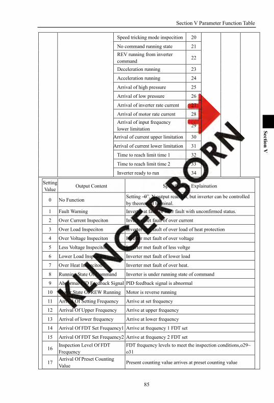
Section V Parameter Function Table
85
Section V
Speed tricking mode inspecition 20
No command running state 21 REV running from inverter command
22
Deceleration running 23
Acceleration running 24
Arrival of high pressure 25
Arrival of low pressure 26
Arrival of inverter rate current 27
Arrival of motor rate current 28 Arrival of input frequency lower limitation 29
Arrival of current upper limitation 30
Arrival of current lower limitation 31
Time to reach limit time 1 32
Time to reach limit time 2 33
Inverter ready to run 34 Setting Value
Output Content Specification Explaination
0 No Function Setting ―0‖, N output reaction, but inverter can be controlled by theoretical terminal.
1 Fault Warning Inverter at fault or after fault with unconfirmed status.
2 Over Current Inspeciton Inverter met fault of over current
3 Over Load Inspeciton Inverter met fault of over load of heat protection
4 Over Voltage Inspeciton Inverter met fault of over voltage
5 Less Voltage Inspeciton Inverter met fault of less voltge
6 Lower Load Inspection Inverter met fault of lower load
7 Over Heat Inspeciton Inverter met fault of over heat.
8 Running State Of Command Inverter is under running state of command
9 Abnormal PID Feedback Signal PID feedback signal is abnormal
10 Motor State Of REW Running Motor is reverse running
11 Arrival Of Setting Frequency Arrive at set frequency
12 Arrival Of Upper Frequency Arrive at upper frequency
13 Arrival of lower frequency Arrive at lower frequency
14 Arrival Of FDT Set Frequency1 Arrive at frequency 1 FDT set
15 Arrival Of FDT Set Frequency2 Arrive at frequency 2 FDT set
16 Inspection Level Of FDT Frequency
FDT frequency levels to meet the inspection conditions,o29~ o31
17 Arrival Of Preset Counting Value
Present counting value arrives at preset counting value

Section V Parameter Function Table
86
Section V
18 Arrival Of Counting Value Upper Limitation
Present counting value arrives at upper limitation of counting value.
19 Program Ruuning One Period Completion
Program runs one period to complete.
20 Inspection In Speed Trick Mode Inverter is under speed trick state, the valid time is A11
21 No Command Running State Inverter is under N command running state
22 REW Command Of Inverter Inverter is under reverse running command
23 Deceleration Running Inverter is under deceleration running
24 Acceleration Running Inverter is under acceleration running
25 Arrival Of High Pressure Arrival at hight pressure
26 Arrival Of Low Pressure Arrival at low pressure
27 Arrival Of Inverter Rate Current Arrival at inverter rate current
28 Arrival Of Motor Rate Current Arrival at motor rate current
29 Arrival Of Input Frequency Lower Limitation
Present set frequency is less than frequency lower limitation
30 Arrival Of Current Upper Limitation
Arrive at current of upper limitation
31 Arrival Of Current Lower Limitation Arrive at current of lower limitation
32 Time to reach limit time 1 Timing action mode refer to o65 configuration
33 Time to reach limit time 2 Timing action mode refer to o66 configuration
34 Inverter ready to run The end of initialization when the drive power on , running command is acceptable.
o25 Output Signal Delay 1 0~32.000 s 0 Y
o26 Output Signal Delay 2 0~32.000 s 0 Y
o27 Output Signal Delay 3 0~32.000 s 0 Y
o28 Output Signal Delay 4 0~32.000 s 0 Y o25~o28 defines o21~o24 output signal reaction delay time, unit is S. Output signal cut off action without delay.
o29 FDT Set Frequency 1 o30~Max frequecy Hz 0.00 Y
o30 FDT Set Frequency 2 0~o29 Hz 0.00 Y
o31 FDT Inspection Range 0.00~5.00 Hz 0.00 Y When the choice of output signal(o21~o24)is set as14, inverter output frequency arrives at or
surpass FDT set frequency 1, the corresponding signal output terminal will react; When inverter output frequency is below of frequency 1 FDT set, the corresponding signal output terminal will not react.
When the output signal options(o21~o24)is set as 15, inverter output frequency reaches or surpass FDT set frequency 2, the corresponding signal output terminal will react;When inverter output frequency is below of frequency 3 FDT set, the corresponding signal output terminal will not react.
When the output signal options (o21~o24)is set as16, inverter will firstly inspect FDT set freuqnecy 1, then inverter output frequency arrives at or surpass FDT set frequency 1, the corresponding signal output terminal will react;After terminal reaction, inverter will inspect FDT set frequency 2, When inverter output frequency is below of frequency 2 FDT set, the corresponding signal output terminal will not react.
o31 frequency inspection range
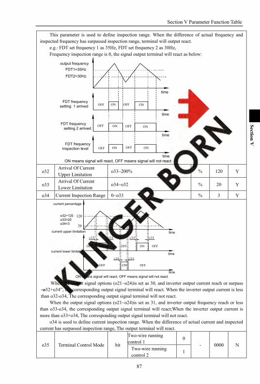
Section V Parameter Function Table
87
Section V
This parameter is used to define inspection range. When the difference of actual frequency and inspected frequency has surpassed inspection range, terminal will output react.
e.g.: FDT set frequency 1 as 35Hz, FDT set frequency 2 as 30Hz, Frequency inspection range is 0, the signal output terminal will react as below:
OFF
OFFOFF
OFF ON
ON ON
ON
time
time
time
output frequency
FDT frequencysetting 1 arrived
FDT1=35Hz
FDT2=30Hz
FDT frequencysetting 2 arrived
ON means signal will react, OFF means signal will not react
OFF ONOFFONFDT frequency
inspection level
time
o32 Arrival Of Current Upper Limitation
o33~200% % 120 Y
o33 Arrival Of Current Lower Limitation o34~o32 % 20 Y
o34 Current Inspection Range 0~o33 % 3 Y
current lower limitation
time
time
timeON means signal will react, OFF means signal will not react
o32=120o33=20o34=3
current percentage
current upper limitation
20
120
ON OFF ONOFF
OFF ON OFF
o34 o34 o34 o34
OFF
o34 o34
When the output signal options (o21~o24)is set as 30, and inverter output current reach or surpass
―o32+o34‖, the corresponding output signal terminal will react. When the inverter output current is less than o32-o34, The corresponding output signal terminal will not react.
When the output signal options (o21~o24)is set as 31, and inverter output frequency reach or less than o33-o34, the corresponding output signal terminal will react;When the inverter output current is more than o33+o34, The corresponding output signal terminal will not react.
o34 is used to define current inspection range. When the difference of actual current and inspected current has surpassed inspection range, The output terminal will react.
o35 Terminal Control Mode bit
Two-wire running control 1 0
- 0000 N Two-wire running control 2
1
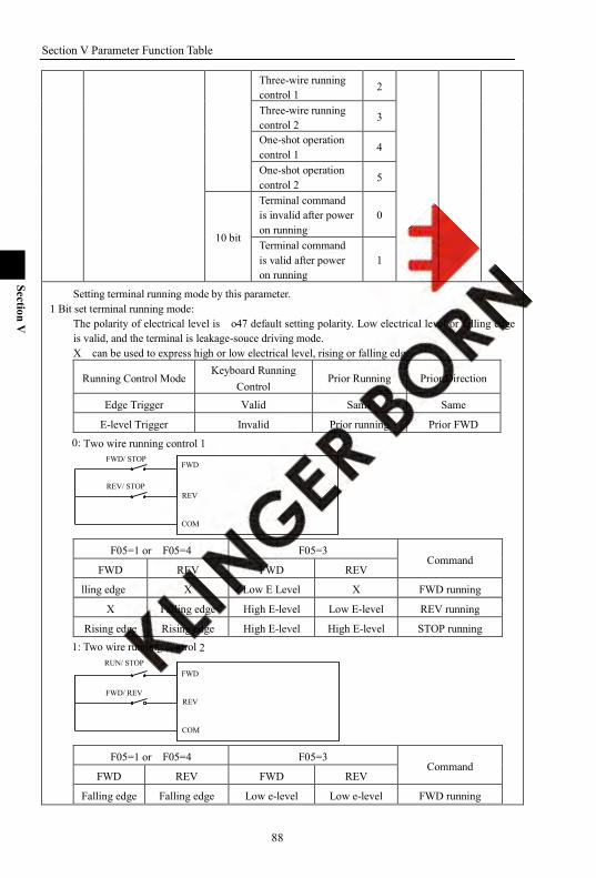
Section V Parameter Function Table
88
Section V
Three-wire running control 1
2
Three-wire running control 2
3
One-shot operation control 1
4
One-shot operation control 2
5
10 bit
Terminal command is invalid after power on running
0
Terminal command is valid after power on running
1
Setting terminal running mode by this parameter. 1 Bit set terminal running mode:
The polarity of electrical level is o47 default setting polarity. Low electrical level or falling edge is valid, and the terminal is leakage-souce driving mode. X can be used to express high or low electrical level, rising or falling edge.
Running Control Mode Keyboard Running
Control Prior Running Prior Direction
Edge Trigger Valid Same Same
E-level Trigger Invalid Prior running Prior FWD 0: Two wire running control 1
FWD/ STOP
REV/ STOP
COM
REV
FWD
F05=1 or F05=4 F05=3 Command
FWD REV FWD REV
lling edge X Low E Level X FWD running
X Falling edge High E-level Low E-level REV running
Rising edge Rising edge High E-level High E-level STOP running 1: Two wire running control 2
FWD
REV
COM
FWD/ REV
RUN/ STOP
F05=1 or F05=4 F05=3 Command
FWD REV FWD REV
Falling edge Falling edge Low e-level Low e-level FWD running
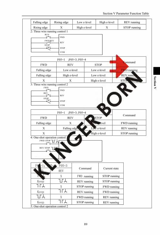
Section V Parameter Function Table
89
Section V
Falling edge Rising edge Low e-level High e-level REV running
Rising edge X High e-level X STOP running 2: Three wire running control 1
FWD
STOP
COM
STOP
RUN
REVFWD/REV
F05=1 ;F05=3; F05=4 Command
FWD REV STOP
Falling edge Low e-level Low e-level FWD running
Falling edge High e-level Low e-level REV running
X X High e-level STOP running 3: Three wire running control 2
REVREV
FWD
STOP
COM
STOP
FWD
F05=1 ;F05=3; F05=4 Command
FWD REV STOP
Falling edge X Low e-level FWD running
X Falling edge Low e-level REV running
X X High e-level STOP running 4: One-shot operation control 1
COM
REV
FWDFWD/ STOP
REV/ STOP
F05=1;F05=4;F05=3 Command Current state
FWD REV
X FWD running STOP running
Keep REV running STOP running
X STOP running FWD running
Keep REV running FWD running
X FWD running REV running
Keep STOP running REV running 5: One-shot operation control 2
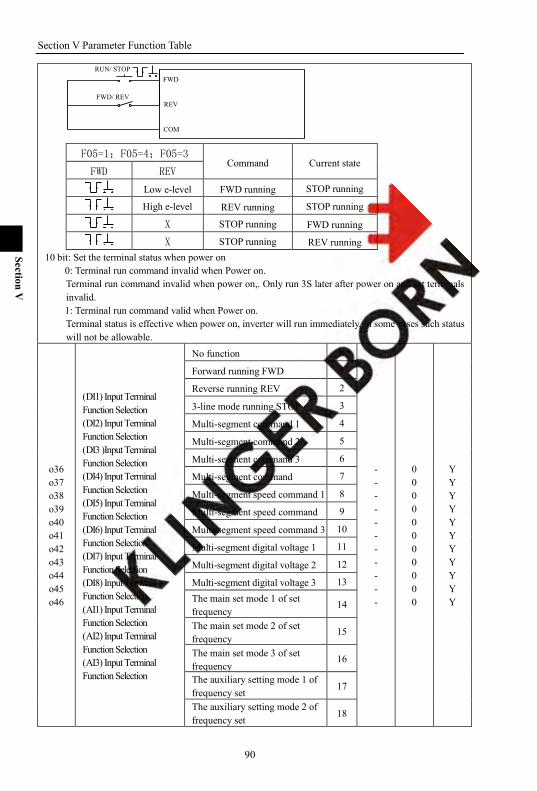
Section V Parameter Function Table
90
Section V
FWD
REV
COM
FWD/ REV
RUN/ STOP
F05=1;F05=4;F05=3 Command Current state
FWD REV
Low e-level FWD running STOP running
High e-level REV running STOP running
X STOP running FWD running
X STOP running REV running 10 bit: Set the terminal status when power on
0: Terminal run command invalid when Power on. Terminal run command invalid when power on,. Only run 3S later after power on and set terminals invalid. 1: Terminal run command valid when Power on. Terminal status is effective when power on, inverter will run immediately, in some cases such status will not be allowable.
o36 o37 o38 o39 o40 o41 o42 o43 o44 o45 o46
(DI1) Input Terminal Function Selection (DI2) Input Terminal Function Selection (DI3 )Input Terminal Function Selection (DI4) Input Terminal Function Selection (DI5) Input Terminal Function Selection (DI6) Input Terminal Function Selection (DI7) Input Terminal Function Selection (DI8) Input Terminal Function Selection (AI1) Input Terminal Function Selection (AI2) Input Terminal Function Selection (AI3) Input Terminal Function Selection
No function 0
- - - - - - - - - - -
0 0 0 0 0 0 0 0 0 0 0
Y Y Y Y Y Y Y Y Y Y Y
Forward running FWD 1
Reverse running REV 2
3-line mode running STOP 3
Multi-segment command 1 4
Multi-segment command 2 5
Multi-segment command 3 6
Multi-segment command 7
Multi-segment speed command 1 8
Multi-segment speed command 9
Multi-segment speed command 3 10
Multi-segment digital voltage 1 11
Multi-segment digital voltage 2 12
Multi-segment digital voltage 3 13 The main set mode 1 of set frequency
14
The main set mode 2 of set frequency
15
The main set mode 3 of set frequency
16
The auxiliary setting mode 1 of frequency set
17
The auxiliary setting mode 2 of frequency set
18

Section V Parameter Function Table
91
Section V
The auxiliary setting mode 3 of frequency set
19
MSS time running 1 20
MSS time running 2 21
MSS time running 3 22
Operation control mode shift 1 23
Operation control mode shift 2 24
Operation control mode shift 3 25
Forward torque limit shift 1 26
Forward torque limit shift 2 27
Forward torque limit shift 3 28
Reverse torque limit shift 1 29
Reverse torque limit shift 2 30
Reverse torque limit shift 3 31
Torque speed shift 32
fault reset command 33
FWD JOG command 34
REV JOG command 35
JOG order (as F35setting ) 36 Acceleration and deceleration prohibition command
37
Motor 1、2 shift 38
Free stop 39
Up command 40
Down command 41 Automation program running fuction cancel
42
Automation program running stop 43
Program running start mode 44
Program running stop mode 45
Pulse counter clearance 46
Pulse counter input 47
Counter loading 48
Upper counter loading 49
External default signal input (level) 50
1pump soft-start 51
1 pump stop 52
2pump soft-start 53
2 pump stop 54
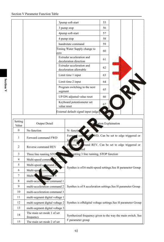
Section V Parameter Function Table
92
Section V
3pump soft-start 55
3 pump stop 56
4pump soft-start 57
4 pump stop 58
handrotate command 59 Timing Water Supply change to zero 60
Extruder acceleration and deceleration direction 61
Extruder acceleration and deceleration allowable 62
Limit time 1 input 63
Limit time 2 input 64
Program switching to the next segment 65
UP/DN adjusted value reset 66
Keyboard potentiometer set value reset 67
External default signal input (edge) 68
Setting Value Output Detail Specification Explaination
0 No function N- function
1 Forward command FWD Forward command FWD, Can be set to edge triggered or level-triggered
2 Reverse command REV Reverse command REV, Can be set to edge triggered or level-triggered
3 Three line running STOP o35 setting 3 line running, STOP function
4 Multi-speed command 1
Synthes is of16 multi-speed settings.See H parameter Group 5 Multi-speed command 2
6 Multi-speed command 3
7 Multi-speed command 4
8 multi-acceleration command 1
Synthes is of 8 acceleration settings.See H parameter Group 9 multi-acceleration command 2
10 multi-acceleration command 3
11 multi-segment digital voltage 1
Synthes is of8digital voltage settings.See H parameter Group 12 multi-segment digital voltage 2
13 multi-segment digital voltage 3
14 The main set mode 1 of set frequency Synthesized frequency given to the way the main switch. See
F parameter group 15 The main set mode 2 of set

Section V Parameter Function Table
93
Section V
frequency
16 The main set mode 3 of set frequency
17 The auxiliary setting mode 1 of frequency set 1
Synthesized frequency secondary to the way a given switch. See F parameter set
18 The auxiliary setting mode 2 of frequency set
19 The auxiliary setting mode 3 of frequency set
20 MSS timing running 1
Synthes is of segment8 run time setting. See H parameter set. 21 MSS timing running 2
22 MSS timing running 3
23 Operation control mode shift 1
Synthes is of operation mode switching. Read F05 parameter 24 Operation control mode shift 2
25 Operation control mode shift 3
26 Forward torque limit shift 1 Synthes is of reverse torque limit switch.See C parameter set C15 Group
27 Forward torque limit shift 2
28 Forward torque limit shift 3
29 Reverse torque limit shift 1 Synthes is of reverse torque limit switch.See C parameter set C16 Group
30 Reverse torque limit shift 2
31 Reverse torque limit shift 3
32 Torque speed shift
Vector control mode, speed control mode and torque control mode switching. Disconnected status: Speed Control Closed Status: torque control Detail C parameter set C18
33 Fault reset command Edge-triggered, the fault occurred on the current failure to confirm or not confirm
34 FWD JOG command JOG forward running command
35 REV JOG command JOG reverse running command
36 JOG command(as F35 setting) JOGrunning command,direction,set a direction in accordance with F35.
37 Acceleration and deceleration forbid commandr
To maintain the current state to prohibit the acceleration and deceleration movements.
38 Motor 1、2 shift Motor 1、2 change Invalid status : Motor 1 Valid status : Motor 2
39 Free stop Free stop:After free stop, no start command,after 1s, allows running again
40 Up command Up order, detail A38~A42
41 Down command Down order, detail A38~A42
42 Auto-run feature programs canceled
Cancle program running function
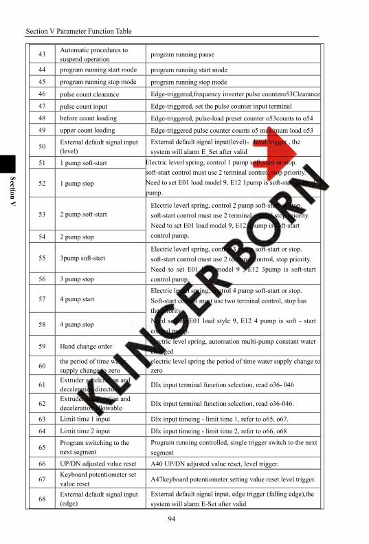
Section V Parameter Function Table
94
Section V
43 Automatic procedures to suspend operation
program running pause
44 program running start mode program running start mode
45 program running stop mode program running stop mode
46 pulse count clearance Edge-triggered,frequency inverter pulse countero53Clearance
47 pulse count input Edge-triggered, set the pulse counter input terminal
48 before count loading Edge-triggered, pulse-load preset counter o53counts to o54
49 upper count loading Edge-triggered pulse counter counts o5 maximum load o53
50 External default signal input (level)
External default signal input(level),level trigger , the system will alarm E_Set after valid
51 1 pump soft-start Electric leverl spring, control 1 pump soft-start or stop. soft-start control must use 2 terminal control, stop priority. Need to set E01 load model 9, E12 1pump is soft-start control pump.
52 1 pump stop
53 2 pump soft-start Electric leverl spring, control 2 pump soft-start or stop. soft-start control must use 2 terminal control,stop priority. Need to set E01 load model 9, E12 2pump is soft-start control pump. 54 2 pump stop
55 3pump soft-start Electric leverl spring, control 3 pump soft-start or stop. soft-start control must use 2 terminal control, stop priority. Need to set E01 load model 9 , E12 3pump is soft-start control pump. 56 3 pump stop
57 4 pump start Electric leverl spring, control 4 pump soft-start or stop. Soft-start control must use two terminal control, stop has the priority. Need setting E01 load style 9, E12 4 pump is soft - start control pump.
58 4 pump stop
59 Hand change order electric level spring, automation multi-pump constant water changed
60 the period of time water supply change to zero
electric level spring the period of time water supply change to zero
61 Extruder acceleration and deceleration direction DIx input terminal function selection, read o36- 046
62 Extruder acceleration and deceleration allowable DIx input terminal function selection, read o36-046.
63 Limit time 1 input DIx input timeing - limit time 1, refer to o65, o67.
64 Limit time 2 input DIx input timeing - limit time 2, refer to o66, o68
65 Program switching to the next segment
Program running controlled, single trigger switch to the next segment
66 UP/DN adjusted value reset A40 UP/DN adjusted value reset, level trigger.
67 Keyboard potentiometer set value reset A47keyboard potentiometer setting value reset level trigger.
68 External default signal input (edge)
External default signal input, edge trigger (falling edge),the system will alarm E-Set after valid
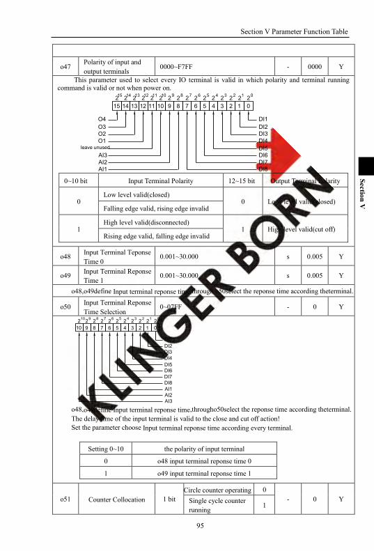
Section V Parameter Function Table
95
Section V
o47 Polarity of input and output terminals
0000~F7FF - 0000 Y
This parameter used to select every IO terminal is valid in which polarity and terminal running command is valid or not when power on.
15 14 13 12 11 10 9 8 7 6 5 4 3 2 1 02 2 2 2 2 2 2 2 2 2 2 2 2 2 2 214 13 0123456789101112
DI1DI2DI3DI4DI5DI6DI7DI8AI1
AI2AI3
15
O4O3O2O1
leave unused
0~10 bit Input Terminal Polarity 12~15 bit Output Terminal Polarity
0
Low level valid(closed) 0 Lo w level valid(closed)
Falling edge valid, rising edge invalid
1 High level valid(disconnected)
1 High level valid(cut off) Rising edge valid, falling edge invalid
o48 Input Terminal Teponse Time 0
0.001~30.000 s 0.005 Y
o49 Input Terminal Reponse Time 1 0.001~30.000 s 0.005 Y
o48,o49define Input terminal reponse time,through o50select the reponse time according theterminal.
o50 Input Terminal Reponse Time Selection
0~07FF - 0 Y
DI8DI7DI6DI5DI4DI3DI2DI1
7 6 5 4 3 2 1 0222222220123456710 9 8
2 2 28910
AI1AI2AI3
o48,o49define Input terminal reponse time,througho50select the reponse time according theterminal. The delay time of the input terminal is valid to the close and cut off action! Set the parameter choose Input terminal reponse time according every terminal.
Setting 0~10 the polarity of input terminal
0 o48 input terminal reponse time 0
1 o49 input terminal reponse time 1
o51 Counter Collocation 1 bit Circle counter operating 0
- 0 Y Single cycle counter running
1
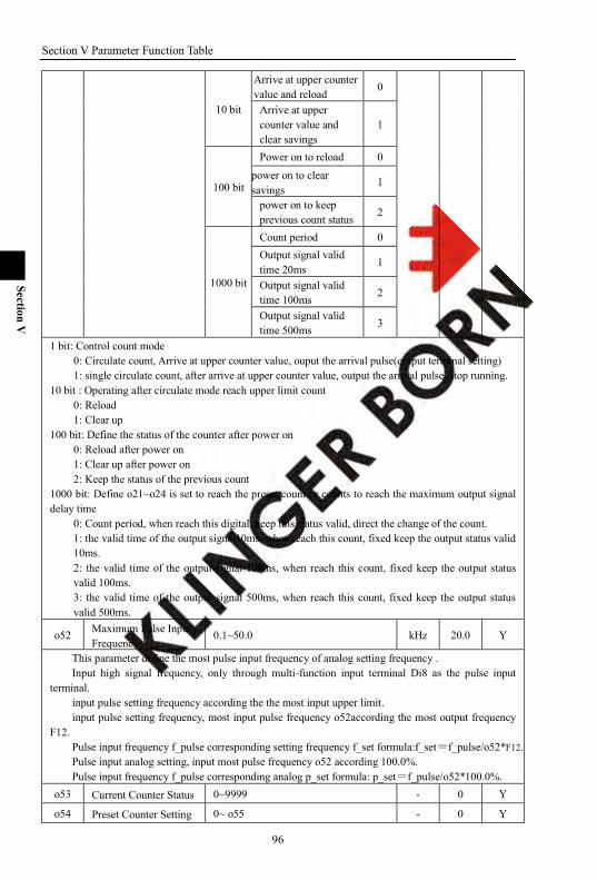
Section V Parameter Function Table
96
Section V
10 bit
Arrive at upper counter value and reload
0
Arrive at upper counter value and clear savings
1
100 bit
Power on to reload 0 power on to clear savings
1
power on to keep previous count status 2
1000 bit
Count period 0 Output signal valid time 20ms
1
Output signal valid time 100ms 2
Output signal valid time 500ms 3
1 bit: Control count mode 0: Circulate count, Arrive at upper counter value, ouput the arrival pulse(output terminal setting) 1: single circulate count, after arrive at upper counter value, output the arrival pulse, stop running.
10 bit : Operating after circulate mode reach upper limit count 0: Reload 1: Clear up
100 bit: Define the status of the counter after power on 0: Reload after power on 1: Clear up after power on 2: Keep the status of the previous count
1000 bit: Define o21~o24 is set to reach the preset count or counts to reach the maximum output signal delay time
0: Count period, when reach this digital, keep this status valid, direct the change of the count. 1: the valid time of the output signal10ms, when reach this count, fixed keep the output status valid 10ms. 2: the valid time of the output signal 100ms, when reach this count, fixed keep the output status valid 100ms. 3: the valid time of the output signal 500ms, when reach this count, fixed keep the output status valid 500ms.
o52 Maximum Pulse Input Frequency
0.1~50.0 kHz 20.0 Y
This parameter define the most pulse input frequency of analog setting frequency . Input high signal frequency, only through multi-function input terminal Di8 as the pulse input
terminal. input pulse setting frequency according the the most input upper limit. input pulse setting frequency, most input pulse frequency o52according the most output frequency
F12. Pulse input frequency f_pulse corresponding setting frequency f_set formula:f_set=f_pulse/o52*F12. Pulse input analog setting, input most pulse frequency o52 according 100.0%. Pulse input frequency f_pulse corresponding analog p_set formula: p_set=f_pulse/o52*100.0%.
o53 Current Counter Status 0~9999 - 0 Y
o54 Preset Counter Setting 0~ o55 - 0 Y

Section V Parameter Function Table
97
Section V
o55 Upper Limit Counter Setting
o54~9999 - 9999 Y
DiX counting
o21
o22
0 1 2 3 4 5 6 3 4 5 6 3
o54
o55
T
Tthe thousand of O51 set t
o55T
o54T
When the pulse signal of the input terminal satisfy with the preset condition, Yi terminal output the
corresponding indication. 1 、Selection of Input terminal DiX(X=1~8)
Input terminal is set to ―pulse count input ‖, and set o54、o55. Input terminal is set to ―pulse counter clear‖, after terminal works, counter is cleared. Input terminal is set to ―upload of pulse count value‖, after terminal works, counter uploads preset
count value. Input terminal is set to―upload of upper count value‖,after terminal works,counter uploads the upper
count value. 2 、Selection of Output Terminal o21~o24
o21set the arrival of preset count, the effective time of output signal after reaching up count value is set by o51.
o22 set the arrival of up count value, the effective time of output signal after arriving at the upper count value is set by o51.
Frequency range of counting pulse signal: 0~100Hz.
o56 Virtual Terminal Effective Selection
0000~F7FF - 0000 Y
15 14 13 12 11 10 9 8 7 6 5 4 3 2 1 02 2 2 2 2 2 2 2 2 2 2 2 2 2 2 214 13 0123456789101112
DI1DI2DI3DI4DI5DI6DI7DI8AI1
AI2AI3
15
O4O3O2O1
leave unused
Setting 0~10 Virtual terminal valid choose
0 Actual input terminal valid
1 Virtual input terminal valid This parameter is used to select a terminal whether each virtual terminal functionality is valid.
o57 DI1~4 Terminal Status 0000~1111 - - Y
o58 DI5~8 Terminal Status 0000~1111 - - Y
o59 AI1~3 Terminal Status 000~111 - - Y
o60 O1~4 Terminal Status 0000~1111 - - Y Make the actual terminal can only be effective check terminal state. Make the Virtual terminal can only be effective through register check terminal state.
o61 o62
PL1 Pulse Output PL2 Pulse Output
No action 0 - -
0 0
Y Y Set frequency 1
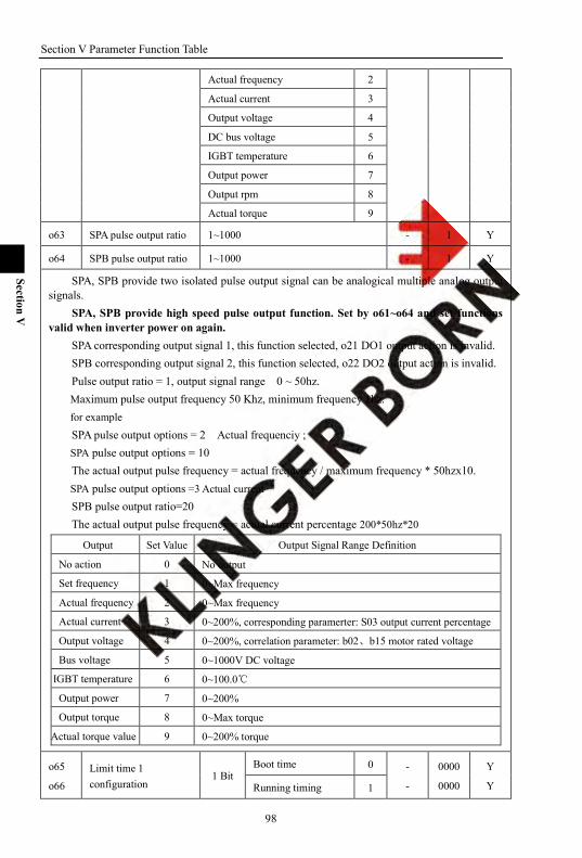
Section V Parameter Function Table
98
Section V
Actual frequency 2
Actual current 3
Output voltage 4
DC bus voltage 5
IGBT temperature 6
Output power 7
Output rpm 8
Actual torque 9
o63 SPA pulse output ratio 1~1000 - 1 Y
o64 SPB pulse output ratio 1~1000 - 1 Y
SPA, SPB provide two isolated pulse output signal can be analogical multiple analog output signals.
SPA, SPB provide high speed pulse output function. Set by o61~o64 and set functions valid when inverter power on again.
SPA corresponding output signal 1, this function selected, o21 DO1 output action is invalid. SPB corresponding output signal 2, this function selected, o22 DO2 output action is invalid. Pulse output ratio = 1, output signal range 0 ~ 50hz. Maximum pulse output frequency 50 Khz, minimum frequency 1hz. for example
SPA pulse output options = 2 Actual frequenciy ; SPA pulse output options = 10 The actual output pulse frequency = actual frequency / maximum frequency * 50hzx10. SPA pulse output options =3 Actual current SPB pulse output ratio=20 The actual output pulse frequency = actual current percentage 200*50hz*20
Output Set Value Output Signal Range Definition
No action 0 No output
Set frequency 1 0~Max frequency
Actual frequency 2 0~Max frequency
Actual current 3 0~200%, corresponding paramerter: S03 output current percentage
Output voltage 4 0~200%, correlation parameter: b02、b15 motor rated voltage
Bus voltage 5 0~1000V DC voltage
IGBT temperature 6 0~100.0
Output power 7 0~200%
Output torque 8 0~Max torque
Actual torque value 9 0~200% torque
o65
o66 Limit time 1 configuration
1 Bit Boot time 0 -
-
0000
0000
Y
Y Running timing 1
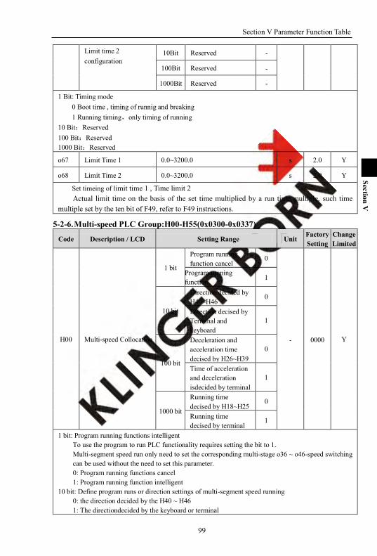
Section V Parameter Function Table
99
Section V
Limit time 2 configuration
10Bit Reserved -
100Bit Reserved -
1000Bit Reserved -
1 Bit: Timing mode 0 Boot time , timing of runnig and breaking 1 Running timing,only timing of running
10 Bit:Reserved 100 Bit:Reserved 1000 Bit:Reserved
o67 Limit Time 1 0.0~3200.0 s 2.0 Y
o68 Limit Time 2 0.0~3200.0 s 2.0 Y
Set timeing of limit time 1 , Time limit 2 Actual limit time on the basis of the set time multiplied by a run time multiple, such time
multiple set by the ten bit of F49, refer to F49 instructions.
5-2-6. Multi-speed PLC Group:H00-H55(0x0300-0x0337)
Code Description / LCD Setting Range Unit Factory Setting
Change Limited
H00 Multi-speed Collocation
1 bit
Program running function cancel
0
- 0000 Y
Program running function
1
10 bit
Direction decided by H40~H46 0
Direction decised by Terminal and keyboard
1
100 bit
Deceleration and acceleration time decised by H26~H39
0
Time of acceleration and deceleration isdecided by terminal
1
1000 bit
Running time decised by H18~H25
0
Running time decised by terminal
1
1 bit: Program running functions intelligent To use the program to run PLC functionality requires setting the bit to 1. Multi-segment speed run only need to set the corresponding multi-stage o36 ~ o46-speed switching can be used without the need to set this parameter. 0: Program running functions cancel 1: Program running function intelligent
10 bit: Define program runs or direction settings of multi-segment speed running 0: the direction decided by the H40 ~ H46 1: The directiondecided by the keyboard or terminal

Section V Parameter Function Table
100
Section V
100 bit:Define program runs or acceleration and deceleration time settings of multi-segment speed running 0: deceleration time decided by the H26 ~ H39 1: The acceleration and deceleration time determined by terminal
1000 bit: Set running time of defined program running 0: running-time decided by the H18 ~ H25 1: Running time decided by terminal
H01 Program Running Configuration
1 bit sequence control 0
- 0710 Y
terminal control 1
10 bit Program running start segment
0~15
100 bit Program running end segment 0~15
1000 bit
Output signal valid time 8ms 0
Output signal valid time 20ms 1
Output signal valid time 100ms 2
Output signal valid time 500ms 3
1 bit: program run control mode。 0: sequential control Run automatically according to the start segment,end segment and program running time of program running. You can use o36 ~ o46 switchover next function , switchover to the next program running . 1: Terminal control Use multi segment control terminal o36 ~ o46 multi segment instruction 1, 2, 3, 4, Control program segment, running time arrives,Running based on the 0 paragraph speed. After Multi - Stage speed control terminal switchover, reevaluate running time Do not use of multi - stage speed control terminal o 36 ~ o46 multi - speed instruction, You can use o36 ~ o46 switchover next function. The terminal control for single trigger, triggered once, program running to next paragraph, running time recalculated.Running time of arrival, Running based on the 0 paragraph speed.
10 bit: defining the start running of the Program 100 bit: Defines the end of the program period 1000 bit: Define effective time of the program output signal
H02 Program Running Mode
1 bit
single-cycle 0
- 0000 Y
Continuous Cycle 1 One-cycle command running 2
10 bit
The zero speed running when pause
0
Fixed-speed running when the suspension
1
100 bit
Stop with the parameters set when stop
0
Stop with the settings of start up
1
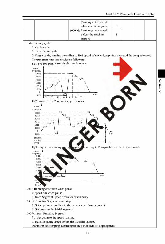
Section V Parameter Function Table
101
Section V
1000 bit
Running at the speed when start up segment
0
Running at the speed before the machine stopped
1
1 bit: Running cycle 0: single cycle 1:continuous cycle 2: Single cycle, running according to H01 speed of the end,stop after accepted the stopped orders. The program runs three styles as following: Eg1:The program is run single - cycle modes
time
7X6X
5X
4X
3X2X
1X
T7T6T5T4T3T2T1
output frequency
60Hz50Hz40Hz30Hz20Hz10Hz
010Hz
Eg2:program run Continuous cycle modes
2X1X
7X6X
5X
4X
3X2X
1X
5X
7X6X
4X
3X2X
1X
time
STOP
program running
putput frequency
60Hz50Hz40Hz30Hz20Hz10Hz
010Hz
Eg3:Program is running in single cycle, According to Paragraph seventh of Speed mode
output frequency
time
program runningSTOP
7X6X
5X
4X
3X2X
1X
60Hz50Hz40Hz30Hz20Hz10Hz
010Hz
10 bit: Running condition when pause
0: speed run when pause 1: fixed Segment Speed operation when pause
100 bit: Running Segment when stop 0: Set stopping according to the parameters of stop segment. 1: Set down to the initial segment
1000 bit: start Running Segment 0: Set down to the speed running 1: Running at the speed before the machine stopped. 100 bit=0 Set stopping according to the parameters of stop segment

Section V Parameter Function Table
102
Section V
1000 bit=0 running at Start Segment
STOP
RUN
T2T1
3X2X
1XF51=00
T1 T2 X
1X2X
3X
dt3' at1'
time
outputfrequency
Eg:100 bit==0 Set stopping according to the parameters of stop segment 1000 bit==1 Running at the speed before the machine stopped.
5X
X+Y=T33X
2X1X
XT2T1
F51=01
3X4X
Y T4
RUN
STOP
dt3' at3'
time
outputfrequency
Eg:100 bit=1 Set down to the initial segment 1000 bit=1 Running at the speed before the machine stopped.
at1'dt1'
3X2X
1X
XT2T1
F51=10,11 1X2X
3X
T1 T2
RUN
STOP
time
outputfrequency
Note :at1':at the time of segment 1 acceleration time ;dt1':at the time of segment 1 deceleration time ;at3'at the time of segment 3 acceleration time;dt3':at the time of segment 3 deceleration time
H03 1 Segment Speed Setting 1X Lower frequency ~ upper frequency Hz 3.00 Y
H04 2 Segment Speed Setting 2X Lower frequency ~ upper frequency Hz 6.00 Y
H05 3 Segment Speed Setting 3X
Lower frequency ~ upper frequency Hz 9.00 Y
H06 4 Segment Speed Setting 4X
Lower frequency ~ upper frequency Hz 12.00 Y
H07 5 Segment Speed Setting 5X
Lower frequency ~ upper frequency Hz 15.00 Y
H08 6 Segment Speed Setting 6X
Lower frequency ~ upper frequency Hz 18.00 Y
H09 7 Segment Speed Setting 7X Lower frequency ~ upper frequency Hz 21.00 Y
H10 8 Segment Speed Setting 8X Lower frequency ~ upper frequency Hz 24.00 Y
H11 9 Segment Speed Setting 9X
Lower frequency ~ upper frequency Hz 27.00 Y
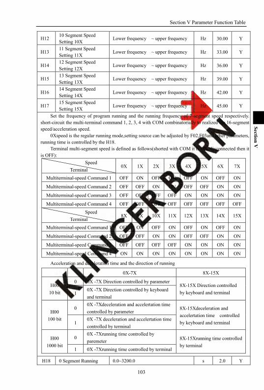
Section V Parameter Function Table
103
Section V
H12 10 Segment Speed Setting 10X
Lower frequency ~ upper frequency Hz 30.00 Y
H13 11 Segment Speed Setting 11X
Lower frequency ~ upper frequency Hz 33.00 Y
H14 12 Segment Speed Setting 12X
Lower frequency ~ upper frequency Hz 36.00 Y
H15 13 Segment Speed Setting 13X
Lower frequency ~ upper frequency Hz 39.00 Y
H16 14 Segment Speed Setting 14X Lower frequency ~ upper frequency Hz 42.00 Y
H17 15 Segment Speed Setting 15X Lower frequency ~ upper frequency Hz 45.00 Y
Set the frequency of program running and the running frequency of 7-segment speed respectively. short-circuit the multi-terminal command 1, 2, 3, 4 with COM combinatorially to realized the 16-segment speed/acceleration speed.
0Xspeed is the regular running mode,setting source can be adjusted by F02,F03and other parameters, running time is controlled by the H18.
Terminal multi-segment speed is defined as follows(shorted with COM it is ON, disconnected then it is OFF):
Speed Terminal
0X 1X 2X 3X 4X 5X 6X 7X
Multiterminal-speed Command 1 OFF ON OFF ON OFF ON OFF ON
Multiterminal-speed Command 2 OFF OFF ON ON OFF OFF ON ON
Multiterminal-speed Command 3 OFF OFF OFF OFF ON ON ON ON
Multiterminal-speed Command 4 OFF OFF OFF OFF OFF OFF OFF OFF Speed
Terminal 8X 9X 10X 11X 12X 13X 14X 15X
Multiterminal-speed Command 1 OFF ON OFF ON OFF ON OFF ON
Multiterminal-speed Command 2 OFF OFF ON ON OFF OFF ON ON
Multiterminal-speed Command 3 OFF OFF OFF OFF ON ON ON ON
Multiterminal-speed Command 4 ON ON ON ON ON ON ON ON
Acceleration and deceleration time and the direction of running
0X-7X 8X-15X
H00 10 bit
0 0X -7X Direction controlled by parameter 8X-15X Direction controlled by keyboard and terminal 1
0X -7X Direction controlled by keyboard and terminal
H00 100 bit
0 0X -7Xdeceleration and accelertation time controlled by parameter
8X-15Xdeceleration and accelertation time controlled by keyboard and terminal 1
0X -7X deceleration and accelertation time controlled by terminal
H00 1000 bit
0 0X -7Xrunning time controlled by paremeter 8X-15Xrunning time controlled
by terminal 1 0X -7Xrunning time controlled by terminal
H18 0 Segment Running 0.0~3200.0 s 2.0 Y
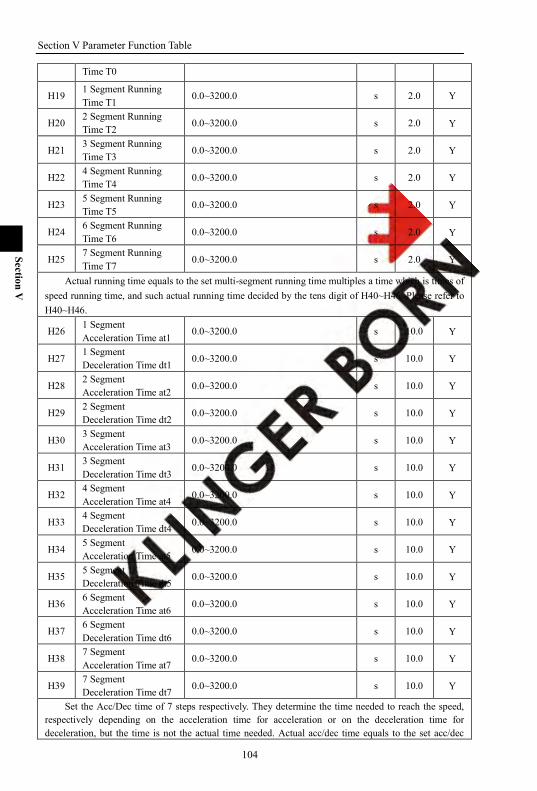
Section V Parameter Function Table
104
Section V
Time T0
H19 1 Segment Running Time T1
0.0~3200.0 s 2.0 Y
H20 2 Segment Running Time T2 0.0~3200.0 s 2.0 Y
H21 3 Segment Running Time T3 0.0~3200.0 s 2.0 Y
H22 4 Segment Running Time T4
0.0~3200.0 s 2.0 Y
H23 5 Segment Running Time T5
0.0~3200.0 s 2.0 Y
H24 6 Segment Running Time T6
0.0~3200.0 s 2.0 Y
H25 7 Segment Running Time T7
0.0~3200.0 s 2.0 Y
Actual running time equals to the set multi-segment running time multiples a time which is times of speed running time, and such actual running time decided by the tens digit of H40~H46. Please refer to H40~H46.
H26 1 Segment Acceleration Time at1
0.0~3200.0 s 10.0 Y
H27 1 Segment Deceleration Time dt1 0.0~3200.0 s 10.0 Y
H28 2 Segment Acceleration Time at2 0.0~3200.0 s 10.0 Y
H29 2 Segment Deceleration Time dt2
0.0~3200.0 s 10.0 Y
H30 3 Segment Acceleration Time at3
0.0~3200.0 s 10.0 Y
H31 3 Segment Deceleration Time dt3
0.0~3200.0 s 10.0 Y
H32 4 Segment Acceleration Time at4
0.0~3200.0 s 10.0 Y
H33 4 Segment Deceleration Time dt4 0.0~3200.0 s 10.0 Y
H34 5 Segment Acceleration Time at5 0.0~3200.0 s 10.0 Y
H35 5 Segment Deceleration Time dt5
0.0~3200.0 s 10.0 Y
H36 6 Segment Acceleration Time at6
0.0~3200.0 s 10.0 Y
H37 6 Segment Deceleration Time dt6
0.0~3200.0 s 10.0 Y
H38 7 Segment Acceleration Time at7
0.0~3200.0 s 10.0 Y
H39 7 Segment Deceleration Time dt7 0.0~3200.0 s 10.0 Y
Set the Acc/Dec time of 7 steps respectively. They determine the time needed to reach the speed, respectively depending on the acceleration time for acceleration or on the deceleration time for deceleration, but the time is not the actual time needed. Actual acc/dec time equals to the set acc/dec
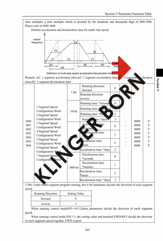
Section V Parameter Function Table
105
Section V
time multiples a time multiple which is decided by the hundreds and thousands digit of H40~H46. Please refer to H40~H46.
Definite acceleration and deceleration time for multi-step speed:
outputfrequency
time
Definition of multi-step speed acceleration/deceleration time
T3T2T1
dt3dt2at2
at1
3X
2X
1X
Remark: at1: 1 segment acceleration time;at2: 2 segment acceleration time;dt2: 2 segment deceleration time;dt3: 3 segment deceleration time.
H40 H41 H42 H43 H44 H45 H46
1 Segment Speed Configuration Word 2 Segment Speed Configuration Word 3 Segment Speed Configuration Word 4 Segment Speed Configuration Word 5 Segment Speed Configuration Word 6 Segment Speed Configuration Word 7 Segment Speed Configuration Word
1 bit
Running direction: forward
0
- - - - - - -
0000 0000 0000 0000 0000 0000 0000
Y Y Y Y Y Y Y
Running direction: reverse
1
10 bit
Running time: *seconds 0
Running time: *munites 1
Running time: *hours 2
Running time: *days 3
100 bit
Acceleration time: *seconds 0
Acceleration time: *munites
1
Acceleration time: *hours
2
Acceleration time: *days 3
1000 bit
Deceleration time: *seconds 0
Deceleration time: *munites
1
Deceleration time: *hours
2
Deceleration time: *days 3 1 bit: Under multi-segment program running, the―1 bit‖parameter decides the direction of each segment speed.
Running Direction Setting Value
forward 0
reverse 1 When running control modeF05=0/1/2,these parameters decide the direction of each segment
speed. When running control mode F05=3, the setting value and terminal FWD/REV decide the direction
of each segment speed together. FWD is prior.
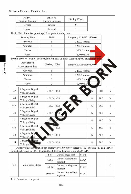
Section V Parameter Function Table
106
Section V
FWD=1 Running direction
REW =1 Running direction Setting Value
forward reverse 0
reverse forward 1
10 bit: Unit of multi-segment speed program running time. Running Time 10 bit Range(e.g.H18~H25=3200.0)
*seconds 0 3200.0 seconds
*minutes 1 3200.0 minutes
*hours 2 3200.0 hours
*days 3 3200.0 days 100 bit, 1000 bit : Unit of acc/deceleration time of multi-segment speed program running
Acceleration / Deceleration time
1000 bit, 100bit Range(e.g.H26~H39=3200.0)
*seconds 0 3200.0 seconds
*minutes 1 3200.0 minutes
*hours 2 3200.0 hours
*days 3 3200.0 days
H47 0 Segment Digital Voltage Giving
-100.0~100.0 % 0.0 Y
H48 1 Segment Digital Voltage Giving
-100.0~100.0 % 10.0 Y
H49 2 Segment Digital Voltage Giving
-100.0~100.0 % 20.0 Y
H50 3 Segment Digital Voltage Giving
-100.0~100.0 % 30.0 Y
H51 4 Segment Digital Voltage Giving
-100.0~100.0 % 40.0 Y
H52 5 Segment Digital Voltage Giving
-100.0~100.0 % 50.0 Y
H53 6 Segment Digital Voltage Giving
-100.0~100.0 % 60.0 Y
H54 7 Segment Digital Voltage Giving
-100.0~100.0 % 70.0 Y
Digital voltage set function can analogy give frequency, select by F02, F03;analogy give PID set or feedback, select by P02, P03;it can be shifted by the input terminal o36~o46.
H55 Multi-speed Status
1 bit Current speed step 0~0xF
- - N
10 bit Current acceleration segment 0~0x7
100 bit Current running time segment
0~0x7
1000 bit Current digit voltage segment
0~0x7
1 bit: Current speed segment
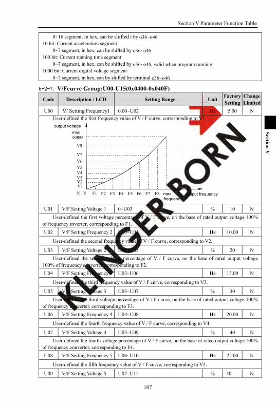
Section V Parameter Function Table
107
Section V
0~16 segment, In hex, can be shifted t by o36~o46 10 bit: Current acceleration segment
0~7 segment, in hex, can be shifted by o36~o46 100 bit: Current running time segment
0~7 segment, in hex, can be shifted by o36~o46, valid when program running 1000 bit: Current digital voltage segment
0~7 segment, in hex, can by shifted by terminal o36~o46
5-2-7. V/Fcurve Group:U00-U15(0x0400-0x040F)
Code Description / LCD Setting Range Unit Factory Setting
Change Limited
U00 V/ Setting Frequency1 0.00~U02 Hz 5.00 N User-defined the first frequency value of V / F curve, corresponding to V1
V8
V7V6V5V4V3V2V1
F1 F2 F3 F4 F5 F6 F7 F8
max output
maxfrequency
(0,0) output frequency
output voltage
U01 V/F Setting Voltage 1 0~U03 % 10 N
User-defined the first voltage percentage of V / F curve, on the base of rated output voltage 100% of frequency inverter, corresponding to F1. U02 V/F Setting Frequency 2 U00~U04 Hz 10.00 N
User-defined the second frequency value of V / F curve, corresponding to V2.
U03 V/F Setting Voltage 2 U01~U05 % 20 N User-defined the second voltage percentage of V / F curve, on the base of rated output voltage
100% of frequency converter, corresponding to F2. U04 V/F Setting Frequency 3 U02~U06 Hz 15.00 N
User-defined the third frequency value of V / F curve, corresponding to V3.
U05 V/F Setting Voltage 3 U03~U07 % 30 N User-defined the third voltage percentage of V / F curve, on the base of rated output voltage 100%
of frequency converter, corresponding to F3. U06 V/F Setting Frequency 4 U04~U08 Hz 20.00 N
User-defined the fourth frequency value of V / F curve, corresponding to V4.
U07 V/F Setting Voltage 4 U05~U09 % 40 N User-defined the fourth voltage percentage of V / F curve, on the base of rated output voltage 100%
of frequency converter, corresponding to F4. U08 V/F Setting Frequency 5 U06~U10 Hz 25.00 N
User-defined the fifth frequency value of V / F curve, corresponding to V5.
U09 V/F Setting Voltage 5 U07~U11 % 50 N

Section V Parameter Function Table
108
Section V
User-defined the fifth voltage percentage of V / F curve, on the base of rated output voltage 100% of frequency converter, corresponding to F5. U10 V/F Setting Frequency 6 U08~U12 Hz 30.00 N
User-defined the sixth frequency value of V / F curve, corresponding to V6.
U11 V/F Setting Voltage 6 U09~U13 % 60 N User-defined the sixth voltage percentage of V / F curve, on the base of rated output voltage 100%
of frequency converter, corresponding to F6. U12 V/F Setting Frequency 7 U10~U14 Hz 35.00 N
User-defined the seventh frequency value of V / F curve, corresponding to V7.
U13 V/F Setting Voltage 7 U11~U15 % 70 N User-defined the seventh voltage percentage of V / F curve, on the base of rated output voltage
100% of frequency converter, corresponding to F7. U14 V/F Setting Frequency 8 U12~most frequency Hz 40.00 N
User-defined the eighth frequency value of V / F curve, corresponding to V8.
U15 V/F Setting Voltage 8 U13~100 % 80 N User-defined the eighth voltage percentage of V / F curve, on the base of rated output voltage 100%
of frequency converter, corresponding to F8.
5-2-8. PID parameter:P00-P12(0x0500-0x050C)
Code Description / LCD Setting Range Unit Factory Setting
Change Limited
P00 PID Configuration
1 bit Unidirectional regulation
0
- 0000 N
Bidirectional regulation 1
10 bit Negative effect 0
Positive effect 1
100 bit
PID fault, N action 0 Warning & Continuous running
1
Warning & Decelerating stop
2
Warning & Free stop 3
1000 bit - -
- - When the inverter receives running command, it can control output frequency automatically in the
PID regulation mode after comparing the setting signal and feedback signal from terminal. The process is explained as following:
PID invertersetting signal
+
-
Mf
feedback signal( = setting signal - feedback signal)
PI8000/PI8100 PID regulation 0: negative action, when Δ>0 is positive, frequency rises and when Δ<0 is negative, frequency
falls.

Section V Parameter Function Table
109
Section V
1: positive action, when Δ>0 is positive, frequency falls and when Δ<0 is negative, frequency rises. PID abnormity treatment:
1: Warning & Continuous running: continue running g after abnormity feedback signal. 2: Warning & Decelerating stop: decelerate and stop after abnormity feedback signal. 3: Warning & Free stop: free stop after abnormity feedback signal .
P01 PID Output Limit 0~100 % 100 Y
The parameter defines the limited range of the output when using PID control.
P02 Feedback Signal Selection
Set frequency by keyboard or RS485
0
- 1 Y
AI1 external analogy giving 1
AI2 external analogy giving 2
AI3 external analogy giving 3 Keyboard potentiometer giving 4
muti-step digital voltage giving 5
Digital pulse set 6 PID feedback signal selection, can select keyboard/Rs485, potentiometer, digital voltage, digital
pulse for feedback signal.
P03 Setting Signal Selection
Set frequency by keyboard or RS485 0
- 2 Y
AI1 external analogy giving 1
AI2 external analogy giving 2
AI3 external analogy giving 3
Keyboard potentiometer giving 4
Multi-step digital voltage giving 5
Digital pulse set 6 PID giving signal selection, can select keyboard/Rs485, potentiometer, digital voltage, digital pulse
for giving signal. P04 Keyboard Set Signal 0.0~100.0 % 50.0 Y
When P03 is 0, the setting pressure set by the keyboard. 0.0~100.0% is 0 to the maximum pressure respectively. P05 PID integral time 0.002~10.000 s 0.250 Y
0.002~10.000s The PID integral time determines the integral regulation speed,the regulation acts on the difference
between PID feedback and setting value by PID regulator. When the difference between PID feedback and setting value is 100% , integral regulator PID
regulator ouput=(P01*F12*12.5%)Hz.(single direction PIDregulation,ignores proportion and differential effect).
If the value is great,the control is stable but response is slow;if the value is little,the system response is rapid but perhaps surge occurs.

Section V Parameter Function Table
110
Section V
difference
operation value
time
time P06 PID Differencial Time 0.000~10.000 s 0.000 Y
0.000~1.000s The parameter determines the regulation intensity, the regulation acts on the change ratio of the
difference between PID feedback and setting value by PID regulator. When the change ratio of the difference between PID feedback and setting value is 100% in the
differential time, PID regulator regulates output to(P01*F12*12.5%)Hz (single direction PID regulation, ignores proportion and integral effect).
If the value is great, the greater the intensity is, the system surge is to occur more easily P07 PID Proportion Gain 0~1000.0 % 100.0 Y
time
time
operation value
difference
0~100.0% The PID Proportion Gain defines regulation intensity of PID regulator, the larger the P is, the more
the intensity is. When proportion gain is 100%,and the difference between PID feedback and getting value is 100%,
PID regulator‘s output is(P01*F12*12.5%)Hz(single direction PID regulation,ignores differential and integral effect).
Proportion gain is the parameter decides PID regulator‘s response extent. If the gain is great, the response is rapid, but if too great, the surge will occur; the gain is little, the
response will lag. P08 PID Sampling Period 0.002~10.000 s 0.010 Y
Set Sampling period of feedback signal. When set this parameter small, the system response speed to the giving and feedback deviation is
slow, but control is stable. When set this parameter low,the system response speed to the giving and feedback deviation is slow,
but easy to cause vibration P09 Deviation Limit 0.0~20.0 % 5.0 Y
Deviation limit effects system control accuracy and stability. When the deviation of feedback signal and giving signal <deviation limit, PID N regulation, keep
output stable. When the deviation of feedback singnal and giving signal >deviation limit, PID regulates according
to deviation, update output P10 PID Fault Detect Time 0.0~3200.0 s 0.0 N
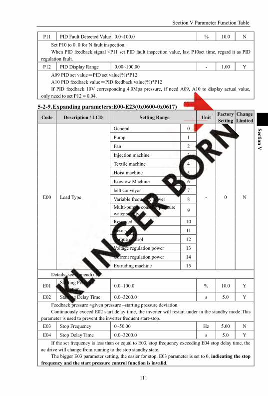
Section V Parameter Function Table
111
Section V
P11 PID Fault Detected Value 0.0~100.0 % 10.0 N Set P10 to 0. 0 for N fault inspection. When PID feedback signal <P11 set PID fault inspection value, last P10set time, regard it as PID
regulation fault. P12 PID Display Range 0.00~100.00 - 1.00 Y
A09 PID set value=PID set value(%)*P12 A10 PID feedback value=PID feedback value(%)*P12 If PID feedback 10V corresponding 4.0Mpa pressure, if need A09, A10 to display actual value,
only need to set P12 = 0.04.
5-2-9. Expanding parameters:E00-E23(0x0600-0x0617)
Code Description / LCD Setting Range Unit Factory Setting
Change Limited
E00 Load Type
General 0
- 0 N
Pump 1
Fan 2
Injection machine 3
Textile machine 4
Hoist machine 5
Kowtow Machine 6
belt conveyor 7
Variable frequency power 8 Multi-pumps constant pressure water supply
9
Reserved 10
Reserved 11
Torque control 12
Voltage regulation power 13
Current regulation power 14
Extruding machine 15
Details, see Appendix IV.
E01 Starting Pressure Deviation
0.0~100.0 % 10.0 Y
E02 Starting Delay Time 0.0~3200.0 s 5.0 Y Feedback pressure <given pressure –starting pressure deviation. Continuously exceed E02 start delay time, the inverter will restart under in the standby mode.This
parameter is used to prevent the inverter frequent start-stop. E03 Stop Frequency 0~50.00 Hz 5.00 N
E04 Stop Delay Time 0.0~3200.0 s 5.0 Y If the set frequency is less than or equal to E03, stop frequency exceeding E04 stop delay time, the
ac drive will change from running to the stop standby state. The bigger E03 parameter setting, the easier for stop, E03 parameter is set to 0, indicating the stop
frequency and the start pressure control function is invalid.
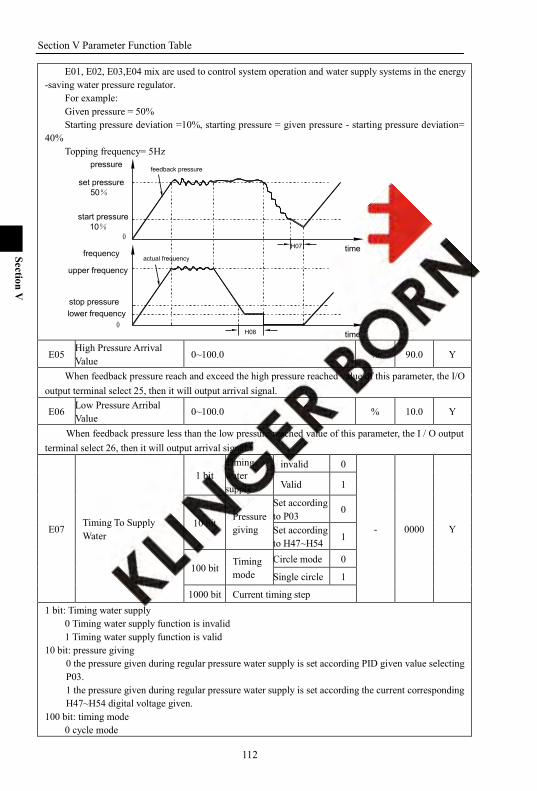
Section V Parameter Function Table
112
Section V
E01, E02, E03,E04 mix are used to control system operation and water supply systems in the energy -saving water pressure regulator.
For example: Given pressure = 50% Starting pressure deviation =10%, starting pressure = given pressure - starting pressure deviation=
40% Topping frequency= 5Hz
actual frequency
H08
H07
0
upper frequency
time
lower frequencystop pressure
frequency
pressurefeedback pressure
start pressure 10%
time
set pressure 50%
0
E05 High Pressure Arrival Value
0~100.0 % 90.0 Y
When feedback pressure reach and exceed the high pressure reached value of this parameter, the I/O output terminal select 25, then it will output arrival signal.
E06 Low Pressure Arribal Value
0~100.0 % 10.0 Y
When feedback pressure less than the low pressure reached value of this parameter, the I / O output terminal select 26, then it will output arrival signal.
E07 Timing To Supply Water
1 bit Timing water supply
invalid 0
- 0000 Y
Valid 1
10 bit Pressure giving
Set according to P03
0
Set according to H47~H54 1
100 bit Timing mode
Circle mode 0
Single circle 1
1000 bit Current timing step 1 bit: Timing water supply
0 Timing water supply function is invalid 1 Timing water supply function is valid
10 bit: pressure giving 0 the pressure given during regular pressure water supply is set according PID given value selecting P03. 1 the pressure given during regular pressure water supply is set according the current corresponding H47~H54 digital voltage given.
100 bit: timing mode 0 cycle mode
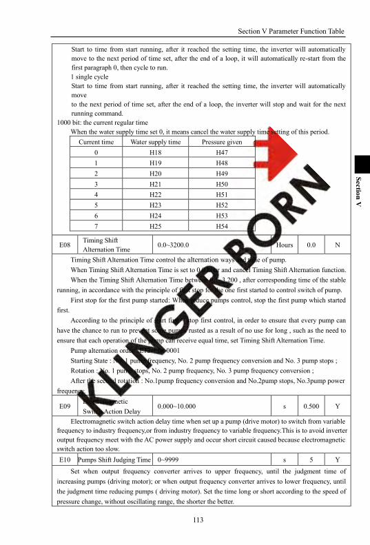
Section V Parameter Function Table
113
Section V
Start to time from start running, after it reached the setting time, the inverter will automatically move to the next period of time set, after the end of a loop, it will automatically re-start from the first paragraph 0, then cycle to run. 1 single cycle Start to time from start running, after it reached the setting time, the inverter will automatically move to the next period of time set, after the end of a loop, the inverter will stop and wait for the next running command.
1000 bit: the current regular time When the water supply time set 0, it means cancel the water supply time setting of this period.
Current time Water supply time Pressure given 0 H18 H47 1 H19 H48 2 H20 H49 3 H21 H50 4 H22 H51 5 H23 H52 6 H24 H53 7 H25 H54
E08 Timing Shift Alternation Time
0.0~3200.0 Hours 0.0 N
Timing Shift Alternation Time control the alternation ways and time of pump. When Timing Shift Alternation Time is set to 0.0 hour and cancel Timing Shift Alternation function. When the Timing Shift Alternation Time between 0.1~3,200 , after corresponding time of the stable
running, in accordance with the principle of first stop for the one first started to control switch of pump. First stop for the first pump started: When reduce pumps control, stop the first pump which started
first. According to the principle of start first – stop first control, in order to ensure that every pump can
have the chance to run to prevent some pumps rusted as a result of no use for long , such as the need to ensure that each operation of the pump can receive equal time, set Timing Shift Alternation Time.
Pump alternation order : E12 = 0x 0001 Starting State : No. 1 pump frequency, No. 2 pump frequency conversion and No. 3 pump stops ; Rotation : No. 1 pump stops, No. 2 pump frequency, No. 3 pump frequency conversion ; After the second rotation : No.1pump frequency conversion and No.2pump stops, No.3pump power
frequency.
E09 Electromagnetic Switch Action Delay
0.000~10.000 s 0.500 Y
Electromagnetic switch action delay time when set up a pump (drive motor) to switch from variable frequency to industry frequency,or from industry frequency to variable frequency.This is to avoid inverter output frequency meet with the AC power supply and occur short circuit caused because electromagnetic switch action too slow. E10 Pumps Shift Judging Time 0~9999 s 5 Y
Set when output frequency converter arrives to upper frequency, until the judgment time of increasing pumps (driving motor); or when output frequency converter arrives to lower frequency, until the judgment time reducing pumps ( driving motor). Set the time long or short according to the speed of pressure change, without oscillating range, the shorter the better.

Section V Parameter Function Table
114
Section V
Drives add or subtract pump control with E12 Water Supply Configuration Add pump order No. 1 pump → No. 2 pump → No. 3 pump → No. 4 pump. Reduce pump order No. 4 pump → No. 1 pump → No. 2 pump → No. 3 pump. If the current : No. 1 pump frequency, No. 2 pump frequency, No. 3 pump convert frequency after reduce pump: No. 1 pump frequency, No. 2 pump convert frequency, after add pump: 1 pump frequency, No. 2 pump frequency, No. 4 pump convert frequency after reduce pump :No. 1 pump frequency, No. 2 pump convert frequency, after reduce pump: No. 1 pump frequency, after add pump: No. 1 pump frequency, No. 3 pump convert frequency after add pump: No. 3 pump frequency No. 4 pump convert frequency after add pump: No. 1 pump frequency, No. 3 pump frequency No. 4 pump. frequency ,No. 2 pump
converter frequency,
E11 Constant Pressure Water Supply Configuration
1 bit Stop mode
all pumps slow down stop 0
- 0000 N
Variable frequency pump stop
1
Free stop 2 Water supply Pump stop
3
10 bit
Pumps status when fault occurs
Keep current situation
0
All-pumps stop 1
100 bit
Alternation shift mode
Variable frequency to working frequency
0
Variable frequency to stop
1
1000 bit Pump status keep
Keep status 0
Stop reset 1
1 bit : Stop mode 0 All slow down, all pumps in turn slowing down. 1 variable frequency pump stop:variable frequency pump stop running,variable frequency pump and soft start pump under frequency keep running. Stop power frequency pump,you need to use o36~o46parking command or keyboard input terminal free multi - function keys MF1, MF2 set to 2 : Free Parking function. 2 Free stop, all pumps free stop After free stop,E11 1000bit pump reset according to the order start and stop,but reorder according to E12 multi - pumps configuration. 3 Water supply pump stops,only those constant pressure water supplying pumps stop,soft start pump keep running under pump frequency. Stop soft - starting pump, you need to use stop command of the soft star pump for o36 ~ o46 input

Section V Parameter Function Table
115
Section V
terminal or keyboard multi - function keys MF1, MF2 set to 2 : Free stop function. 10 bit: Treatment under fault pump states
0 maintain the status quo, when inverter failure, stop the current variable frequency pump operation and other power - frequency operation of variable frequency pump and soft start pump maintain the status quo Fault occurs, if the following breakdown, select fault treatment according to failure action.
12 E.PId regulating fault
13 E.OHt Motor over heated fault
14 E.OL2 Motor over loading fault
15 E.PG PG fault
16 E.PHo Inverter output Phase lost
17 E.COA RS485 communication A fault
18 E.COb RS485 communication B fault The feature only applies to the fault under the mode allowing fault runs. The fault is not allowed to run, all stop. 1 All pump stop, when inverter failure, all pumps free stop.
100 Bit:Soft start switching mode 0 Convert frequency to power frequency, frequency control of the pump current increases the speed to the frequency, the rotation of the pump start and stop switch control or soft start pump 1 Frequency conversion to stop, stopped the current frequency conversion control of pump and pump rotation switch or soft start pump start - stop control.
1000 Bit : pumping States maintain 0 Maintaining state, After multi pumps constant pressure water supply stop, keep the current multipumps at the first start- first stop order. 1 Stopping reset , After multi pumps constant pressure water supply stop , E12 multipumps configuration reorder multi - pump at the stop order.
E12 Multi-pumps Configuration
1 bit
Pump 1 invalid 0
- 0001 N
Pump 1 variable frequency to control pump
1
Pump 1 soft starts to control pump
2
10 bit
Pump 2 invalid 0 Pump 2 variable frequency to control pump
1
Pump 2 soft starts to control pump
2
100 bit
Pump 3 invalid 0 Pump 3 variable frequency to control pump
1
Pump 3 soft starts to control pump 2
1000 bit Pump 4 invalid 0

Section V Parameter Function Table
116
Section V
Pump 4 variable frequency to control pump
1
Pump 4 soft starts to control pump 2
Under Multi-pump control mode, set the control mode of each pump.
E13 Multi-pumps Status
1 bit
Pump 1 stop 0
- 0000 N
Pump 1 run in variable frequency
1
Pump 1 run in working frequency
2
10 bit
Pump 2 stop 0 Pump 2 run in variable frequency
1
Pump 2 run in working frequency
2
100 bit
Pump 3 stop 0 Pump 3 run in variable frequency
1
Pump 3 run in working frequency
2
1000 bit
Pump 4 stop 0 Pump 4 run in variable frequency 1
Pump 4 run in working frequency
2
Under Multi-pump control mode, displays the status of each pump.
E14 Soft Starting Pump Control
1 bit
Pump 1 soft-no command 0
- 0000 Y
Pump 1 soft-stop 1
Pump 1 soft-start 2
10 bit
Pump 1 soft-no command
0
Pump 2 soft-stop 1
Pump 2 soft-start 2
100 bit
Pump 1 soft-no command
0
Pump 3 soft-stop 1
Pump 3 soft-start 2
1000 bit
Pump 1 soft-no command 0
Pump 4 soft-stop 1
Pump 4 soft-start 2
Under Multi-pump control mode, set the control mode of each pump.
E15 User Parameter 0 0~9999 - 0 Y
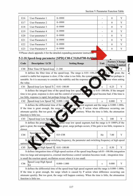
Section V Parameter Function Table
117
Section V
E16 User Parameter 1 0~9999 - 0 Y
E17 User Parameter 2 0~9999 - 0 Y
E18 User Parameter 3 0~9999 - 0 Y
E19 User Parameter 4 0~9999 - 0 Y
E20 User parameter 5 0~9999 - 0 Y
E21 User Parameter 6 0~9999 - 0 Y
E22 User Parameter 7 0~9999 - 0 Y
E23 User Parameter 8 0~9999 - 0 Y
※Please check appendix 4 for the detailed expanding parameter instruction.
5-2-10. Speed-loop parameter [SPD]:C00-C31(0x0700-0x071F)
Code Description / LCD Setting Range Unit Factory Setting
Change Limited
C00 Filter Time Of Speed-loop 2~200 ms 10 Y It defines the filter time of the speed-loop. The range is 0.01~100s.If the value is too great, the
control is stable but response is slow; if the value is too little, the system response is rapid but perhaps is unstable. So it is necessary to consider the stability and the response speed at the same time when setting the value. C01 Speed-loop Low Speed Ti 0.01~100.00 s 0.25 Y
It defines the integral time of the speed-loop low speed. The range is 0.01~100.00s. If the integral time is too great, response is slow and the control of external disturbing signal become bad; if the time is too little, response is rapid, but perhaps brings the surge. C02 Speed-loop Low Speed Td 0.000~1.000 s 0.000 Y
It defines the differential time of the speed-loop low speed segment and the range is 0.000~1.000s. If the time is great enough, the surge which is caused by P action when difference occurring can attenuate quickly. But too great, the surge will happen contrary. When the time is little, the attenuation function is little too. C03 Speed-loop Low Speed P 0~150 % 100 Y
It defines the proportion gain of speed loop low speed segment.And the range is 0~1000%.If the gain is great, the response is rapid, but too great, surge perhaps occurs; if the gain is too little, response is slower.
C04 Speed-loop Low Speed Shift Frequency
0.0~C08 Hz 7.00 Y
It defines low-speed loop switching frequency, the parameter and switching frequency at high-speed optimize Speed-loop PID parameter. C05 Speed Loop High Speed Ti 0.01~100.00 s 0.50 Y
It defines integration time of High-speed section of the speed loop.Range is0.01~100.00s.integration time too large and unresponsive, external interference control variation becomes weak ; integration time is small the reaction speed, oscillation occurs when it is too small.
C06 Speed Loop High Speed Td 0.000~1.000 s 0.000 Y
It defines the differential time of the speed-loop high speed segment and the range is 0.000~1.000s. If the time is great enough, the surge which is caused by P action when difference occurring can attenuate quickly. But too great, the surge will happen contrary. When the time is little, the attenuation function is little too.
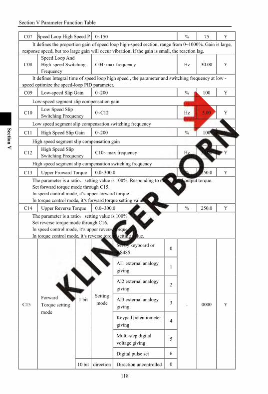
Section V Parameter Function Table
118
Section V
C07 Speed Loop High Speed P 0~150 % 75 Y It defines the proportion gain of speed loop high-speed section, range from 0~1000%. Gain is large,
response speed, but too large gain will occur vibration; if the gain is small, the reaction lag.
C08 Speed Loop And High-speed Switching Frequency
C04~max frequency Hz 30.00 Y
It defines Integral time of speed loop high speed , the parameter and switching frequency at low - speed optimize the speed-loop PID parameter. C09 Low-speed Slip Gain 0~200 % 100 Y
Low-speed segment slip compensation gain
C10 Low Speed Slip Switching Frequency 0~C12 Hz 5.00 Y
Low speed segment slip compensation switching frequency
C11 High Speed Slip Gain 0~200 % 100 Y
High speed segment slip compensation gain
C12 High Speed Slip Switching Frequency C10~ max frequency Hz 30.00 Y
High speed segment slip compensation switching frequency
C13 Upper Froward Torque 0.0~300.0 % 250.0 Y The parameter is a ratio,setting value is 100%. Responding to motor rated output torque. Set forward torque mode through C15. In speed control mode, it‘s upper forward torque. In torque control mode, it‘s forward torque setting value.
C14 Upper Reverse Torque 0.0~300.0 % 250.0 Y The parameter is a ratio,setting value is 100%. Set reverse torque mode through C16. In speed control mode, it‘s upper reverse torque. In torque control mode, it‘s reverse torque setting value.
C15 Forward Torque setting mode
1 bit Setting mode
Set by keyboard or RS485
0
- 0000 Y
AI1 external analogy giving
1
AI2 external analogy giving
2
AI3 external analogy giving
3
Keypad potentiometer giving
4
Multi-step digital voltage giving
5
Digital pulse set 6
10 bit direction Direction uncontrolled 0

Section V Parameter Function Table
119
Section V
Direction controlled 1
C16 Reverse Torque setting mode
1 bit Setting mode
Set by keyboard or RS485
0
- 0000 Y
AI1 external analogy 1
AI2 external analogy giving
2
AI3 external analogy giving
3
Keypad potentiometer giving
4
Multi-step digital voltage giving
5
Digital pulse set 6
10 bit direction Direction uncontrolled 0
Direction controlled 1
C17 Torque Set Gain 0.0~300.0 % 200.0 Y C15 1 bit:Setting mode C16 1 bit:Setting mode
0 Set by keyboard or RS485 Responding to C13/C14
1 AI1 external analog setting As per AI1 external analog setting
2 AI2 external analog setting As per AI2 external analog setting
3 AI3 external analog setting As per AI3 external analog setting
4 Keyboard potentiometer setting As per keyboard potentiometer setting
5 Multi segment digital voltage setting As per multi segment digital voltage setting
6 Digital Pulse Setting As per digital pulse setting
While the unit digital of C15,C16 is 1—6, the torque up-limit of C13,C14 is for checking. C15 10 bit: Direction Control C16 10 bit: Direction Control
0: No control Direction Direction is controlled by terminal or keyboard 1:Control Direction Setting value of forward torque > setting value of reverse torque, forward direction. Setting value of forward torque < setting value of reverse torque, reverse direction. C13 upper forward torque =setting value percentage * C17 torque given gain. C14 upper reverse torque =setting value percentage * C17 torque given gain. Such as: C15 forward torque setting way=4 keyboard potentiometer setting. C16 reverse torque setting way=4 keyboard potentiometer setting. Forward/reverse both can control direction, C15=0x14,C16=0x14.
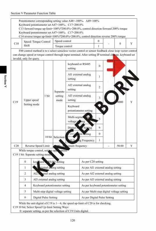
Section V Parameter Function Table
120
Section V
Potentiometer corresponding setting value A48=-100%,A49=100% Keyboard potentiometer set A47=100%,C17=200.0% C13 forward torque up-limit=100%*200.0%=200.0%, control direction forward 200% torque Keyboard potentiometer set A47=100%,C17=200.0% C14 reverse torque up-limit=100%*200.0%=200.0%, control direction reverse 200% torque
C18 Speed /Torque Control Shift
Speed control 0 - 0 Y
Torque control 1 F00 control method is to s select senseless vector control or sensor feedback close loop vector control,
can change speed or torque control through input terminal. After setting IP terminal change, keyboard set invalid, only for query.
C19 Upper speed Setting mode
1 bit Separate setting mode
keyboard or RS485 setting
0
- 0000 Y
AI1 external analog setting
1
AI2 external analog setting
2
AI3 external analog setting
3
Keyboard potentiometer setting
4
Multi-segment digital voltage setting
5
Digital Pulse Setting 6
10 bit Selection C19 Unit bit setting 0
S00 Setting Frequency 1
C20 Reverse Speed Limit 0.00~ Maximum frequency - 50.00 Y While torque control, setting upper speed.
C19 1 bit: Separate setting mode
0 keyboard or RS485 setting As per C20 setting
1 AI1 external analog setting As per AI1 external analog setting
2 AI2 external analog setting As per AI2 external analog setting
3 AI3 external analog setting As per AI3 external analog setting
4 Keyboard potentiometer setting As per keyboard potentiometer setting
5 Multi-step digital voltage setting As per Multi-step digital voltage setting
6 Digital Pulse Setting As per Digital Pulse Setting
While the unit digital of C19 is 1—6, the speed up-limit of C20 is for checking. C19 10 bit; Select Speed Up-limit Setting Ways
0: separate setting, as per the selection of C19 Units digital.
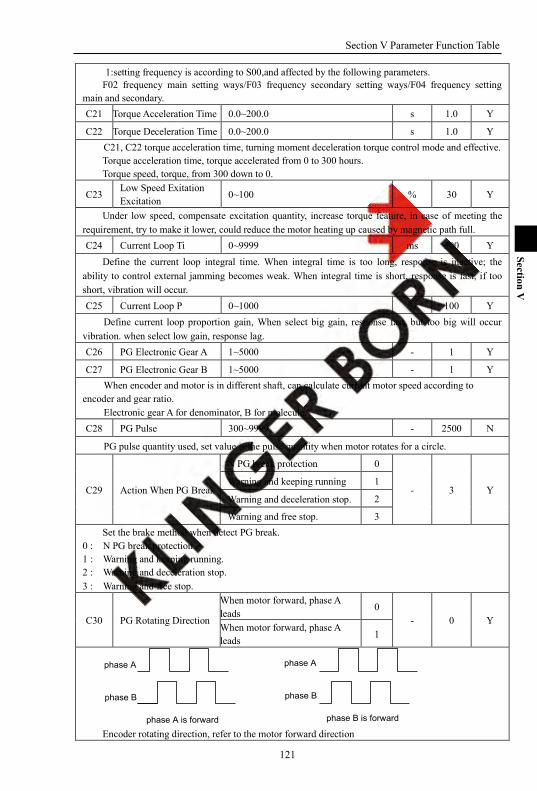
Section V Parameter Function Table
121
Section V
1:setting frequency is according to S00,and affected by the following parameters. F02 frequency main setting ways/F03 frequency secondary setting ways/F04 frequency setting
main and secondary. C21 Torque Acceleration Time 0.0~200.0 s 1.0 Y
C22 Torque Deceleration Time 0.0~200.0 s 1.0 Y C21, C22 torque acceleration time, turning moment deceleration torque control mode and effective. Torque acceleration time, torque accelerated from 0 to 300 hours. Torque speed, torque, from 300 down to 0.
C23 Low Speed Exitation Excitation 0~100 % 30 Y
Under low speed, compensate excitation quantity, increase torque feature, in case of meeting the requirement, try to make it lower, could reduce the motor heating up caused by magnetic path full. C24 Current Loop Ti 0~9999 ms 500 Y
Define the current loop integral time. When integral time is too long, response is inactive; the ability to control external jamming becomes weak. When integral time is short, response is fast, if too short, vibration will occur. C25 Current Loop P 0~1000 % 100 Y
Define current loop proportion gain, When select big gain, response fast, but too big will occur vibration. when select low gain, response lag. C26 PG Electronic Gear A 1~5000 - 1 Y
C27 PG Electronic Gear B 1~5000 - 1 Y When encoder and motor is in different shaft, can calculate current motor speed according to
encoder and gear ratio. Electronic gear A for denominator, B for molecule.
C28 PG Pulse 300~9999 - 2500 N
PG pulse quantity used, set value is the pulse quantity when motor rotates for a circle.
C29 Action When PG Break
N PG break protection 0
- 3 Y Warning and keeping running 1
Warning and deceleration stop. 2
Warning and free stop. 3 Set the brake method when detect PG break.
0 : N PG break protection 1 : Warning and keeping running. 2 : Warning and deceleration stop. 3 : Warning and free stop.
C30 PG Rotating Direction
When motor forward, phase A leads
0 - 0 Y
When motor forward, phase A leads 1
phase A
phase B
phase A is forward
phase A
phase B
phase B is forward Encoder rotating direction, refer to the motor forward direction
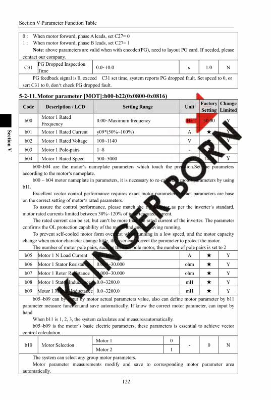
Section V Parameter Function Table
122
Section V
0 : When motor forward, phase A leads, set C27= 0 1 : When motor forward, phase B leads, set C27= 1
Note: above parameters are valid when with encoder(PG), need to layout PG card. If needed, please contact our company.
C31 PG Dropped Inspection Time
0.0~10.0 s 1.0 N
PG feedback signal is 0, exceed C31 set time, system reports PG dropped fault. Set speed to 0, or sert C31 to 0, don‘t check PG dropped fault.
5-2-11. Motor parameter [MOT]:b00-b22(0x0800-0x0816)
Code Description / LCD Setting Range Unit Factory Setting
Change Limited
b00 Motor 1 Rated Frequency 0.00~Maximum frequency Hz 50.00 Y
b01 Motor 1 Rated Current y09*(50%~100%) A Y
b02 Motor 1 Rated Voltage 100~1140 V Y
b03 Motor 1 Pole-pairs 1~8 - 2 Y
b04 Motor 1 Rated Speed 500~5000 rpm 1480 Y
b00~b04 are the motor‘s nameplate parameters which touch the precision.Set the parameters according to the motor‘s nameplate.
b00 ~ b04 motor nameplate in parameters, it is necessary to re-calculate motor parameters by using b11.
Excellent vector control performance requires exact motor parameters. Exact parameters are base on the correct setting of motor‘s rated parameters.
To assure the control performance, please match the right motor as per the inverter‘s standard, motor rated currents limited between 30%~120% of inverter rated current.
The rated current can be set, but can‘t be more than the rated current of the inverter. The parameter confirms the OL protection capability of the motor and energy-saving running.
To prevent self-cooled motor form overheat when running in a low speed, and the motor capacity change when motor character change little, the user can correct the parameter to protect the motor.
The number of motor pole pairs, such as the four pole motor, the number of pole pairs is set to 2 b05 Motor 1 N Load Current 0.0~b01 A Y
b06 Motor 1 Stator Resistance 0.000~30.000 ohm Y
b07 Motor 1 Rotor Resistance 0.000~30.000 ohm Y
b08 Motor 1 Stator Inductance 0.0~3200.0 mH Y
b09 Motor 1 Mutual Inductance 0.0~3200.0 mH Y b05~b09 can by input by motor actual parameters value, also can define motor parameter by b11
parameter measure function.and save automatically. If know the correct motor parameter, can input by hand
When b11 is 1, 2, 3, the system calculates and measuresautomatically. b05~b09 is the motor‘s basic electric parameters, these parameters is essential to achieve vector
control calculation.
b10 Motor Selection Motor 1 0
- 0 N Motor 2 1
The system can select any group motor parameters. Motor parameter measurements modify and save to corresponding motor parameter area
automatically.
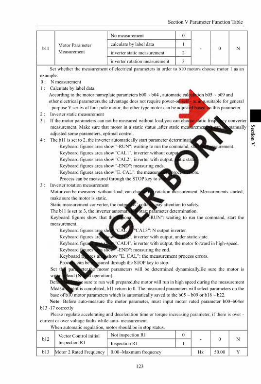
Section V Parameter Function Table
123
Section V
b11 Motor Parameter Measurement
No measurement 0
- 0 N calculate by label data 1
inverter static measurement 2
inverter rotation measurement 3 Set whether the measurement of electrical parameters in order to b10 motors choose motor 1 as an
example. 0 : N measurement 1 : Calculate by label data
According to the motor nameplate parameters b00 ~ b04 , automatic calculation b05 ~ b09 and other electrical parameters,the advantage does not require power-on self - tuning,suitable for general - purpose Y series of four pole motor, the other type motor can be adjusted based on this parameter.
2 : Inverter static measurement 3 : If the motor parameters can not be measured without load,you can choose static frequency converter
measurement. Make sure that motor in a static status ,after static measurement, it can be manually adjusted some parameters, optimal control.
4 : The b11 is set to 2, the inverter automatically start parameter determination. Keyboard figures area show "-RUN": waiting to run the command, start the measurement. Keyboard figures area show "CAL1", inverter without output. Keyboard figures area show "CAL2", inverter with output, static state. Keyboard figures area show "-END": measuring ends. Keyboard figures area show "E. CAL": the measurement process errors. Process can be measured through the STOP key to stop.
3 : Inverter rotation measurement Motor can be measured without load, can choose the rotation measurement. Measurements started, make sure the motor is static. Static measurement converter, the output DC voltage, pay attention to safety. The b11 is set to 3, the inverter automatically start parameter determination. Keyboard figures show that the regional show "-RUN": waiting to run the command, start the measurement.
Keyboard figures area show "CAL1", "CAL3": N output inverter. Keyboard figures area show "CAL2", inverter with output, under static state. Keyboard figures area show "CAL4", inverter with output, the motor forward in high-speed. Keyboard figures area show "-END": measuring the end. Keyboard figures area show "E. CAL": the measurement process errors. Process can be measured through the STOP key to stop.
Set this parameter,the motor parameters will be determined dynamically.Be sure the motor is without load (N-load operation). Before setting,be sure to run well prepared,the motor will run in high speed during the measurement Measurement is completed, b11 return to 0. The measured parameters will select parameters on the base of b10 motor parameters which is automatically saved to the b05 ~ b09 or b18 ~ b22. Note: Before auto-measure the motor parameter, must input motor rated parameter b00~b04or
b13~17 correctly Please regulate accelerating and deceleration time or torque increasing parameter, if there is over -
current or over voltage faults while auto- measurement. When automatic regulation, motor should be in stop status.
b12 Vector Control initial Inspection R1
Not inspection R1 0 - 0 N
Inspection R1 1
b13 Motor 2 Rated Frequency 0.00~Maxmum frequency Hz 50.00 Y

Section V Parameter Function Table
124
Section V
b14 Motor 2 Rated Current y09*(50%~100%) A Y
b15 Motor 2 Rated Voltage 100~1140 V Y
b16 Motor 2 Pole Pairs 1~8 - 2 Y
b17 Motor 2 Rated Speed 500~5000 rpm 1480 Y
b18 Motor 2 N Load Current 0.0~b14 A Y
b19 Motor 2 Stator Resistance 0.000~30.000 ohm Y
b20 Motor 2 Rotator Resistance
0.000~30.000 ohm Y
b21 Motor 2 Stator Inductance
0.0~3200.0 mH Y
b22 Motor 2 Mutual Inductance
0.0~3200.0 mH Y
The 2nd group motor parameters can be set by system. The definition is same with group 1.
5-2-12. System parameter [SYS]:y00-y17(0x0900-0x0911)
Code Description / LCD Setting Range Unit Factory Setting
Change Limited
y00 Reset System Parameter
No action 0
- 0 N
Reset system parameter with keyboard storage1
1
Reset system parameter with keyboard storage 2
2
Reset system parameter with keyboard storage 3 3
Reset system parameter with keyboard storage 4 4
Reset system parameter with factory set value
5
0 : No action 1 : Reset system parameter with keyboard storage 1 2 : Reset system parameter with keyboard storage 2 3 : Reset system parameter with keyboard storage 3 4 : Reset system parameter with keyboard storage 4 5 : Reset system parameter with factory set value
When this parameter set valid, all the function parameter reset to factory setting. The parameters without factory setting will save the previous setting value.
y01 Parameter Upload To Keyboard
No action 0
- 0 N
Reset system parameter with keyboard memory area1
1
Reset system parameter with keyboard memory area2
2
Reset system parameter with keyboard memory area3
3
Reset system parameter with keyboard memory area4
4
Clear up keyboard memory 5

Section V Parameter Function Table
125
Section V
area 1, 2, 3, 4
0 : No action; 1 : Reset system parameter with keyboard memory area1; 2 : Reset system parameter with keyboard memory area2; 3 : Reset system parameter with keyboard memory area3; 4 : Reset system parameter with keyboard memory area4; 5 : Clear up keyboard memory area 1, 2, 3, 4 y02 Lastest Fault record Lastest fault record number mH 0 Y
y03 Fault Record 1
Press [PRG]and [/] key the frequency, crrent and running status of fault time can be known.
- 0 Y
y04 Fault Record 2
y05 Fault Record 3
y06 Fault Record 4
y07 Fault Record 5 These parameters register fault which happen in the last several times, and can inquire about the
value of monitor object at the time of fault by ‗PRG‘ and ―plus or minus‖ key. The monitor object of fault state: 0: Fault type The fault code is expressed as following:
Serial number LED display Fault
0 E.OCP System is disturbed or impacted by instant over current
1 Reserved
2 E.OC3 Over current or over voltage signal from drive circuit.
3 Reversed
4 E.OU Over voltage
5 E.LU Under voltage
6 E.OL Over load
7 E.UL Under load warm
8 E.PHI Power input Phase loss
9 E.EEP EEPROM error
10 E.ntC Over heat
11 E.dAt Time limit fault
12 E.Set External fault
13 Reserved
14 Reserved
15 Reserved
16 E.PID PID regulate fault
17 E. OHt Motor over heat fault
18 E.OL2 Motor over load fault
19 E.PG PG fault
20 E.Pho Inverter output phase-lost
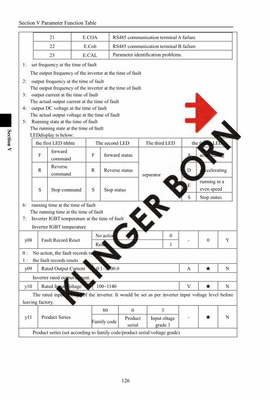
Section V Parameter Function Table
126
Section V
21 E.COA RS485 communication terminal A failure
22 E.Cob RS485 communication terminal B failure
23 E.CAL Parameter identification problems.
1: set frequency at the time of fault
The output frequency of the inverter at the time of fault 2: output frequency at the time of fault
The output frequency of the inverter at the time of fault 3: output current at the time of fault
The actual output current at the time of fault 4: output DC voltage at the time of fault
The actual output voltage at the time of fault 5: Running state at the time of fault
The running state at the time of fault LEDdisplay is below:
the first LED tthhte The second LED The third LED the fourth LED
F forward command
F forward status
separator
A accelerating
R Reverse command
R Reverse status D deccelerating
S Stop command S Stop status E
running in a even speed
S Stop status 6: running time at the time of fault
The running time at the time of fault 7: Inverter IGBT temperature at the time of fault
Inverter IGBT temperature
y08 Fault Record Reset No action 0
- 0 Y Reset 1
0 : No action, the fault records retains 1 : the fault records resets y09 Rated Output Current 0.1~1000.0 A N
Inverter rated output current.
y10 Rated Input Voltage 100~1140 V N
The rated input voltage of the inverter. It would be set as per inverter input voltage level before leaving factory.
y11 Product Series 80 0 3
- N Family code
Product serial
Input oltage grade 1
Product series (set according to family code/product serial/voltage grade)

Section V Parameter Function Table
127
Section V
80 0 3
family code80:8000 serial81:8100 serial
series number input voltage level0: Flow load (F)1:General load (G)2: Middle load (M)3: Heavy load (H)6: TEXDRIVE (S)7: WINDLASS (T)8:JETDRIVE (Z)
1: single phase 220V2: three phase 220V3: three phase 380V4: three phase 460V5: three phase 575V6: three phase 660V9: three phase 1140V
y12 Software Version - - - N
version number
A:official versionB:specialized versionC:beta version
y13 Product Date-- Year YYYY - - N
y14 Product Date -Month/Day MMDD - - N
y15 User Decode Input 0~9999 Set range
- - Y Record password wrongly input times Display info
In the state of locked parameter,LED displays the times of error input. There are three input limit,if input is wrong in continuous three times , the systems will prohibit input of the password . It can prevent testing password in an illegal way, and need restart the machine to input again.
Once the input is right in any time during three times input limit, the parameter is unlocked.
y16 User password key-in
0~9999 Set range
- - Y No password or decode input is correct
code Display info
Parameter lock-in code The parameter sets the password , and the range is 0 ~ 9999 . After setting the password , parameter
locks and keyboard displays ―code‖; if the password is unlocked or password input is right, the keyboard will display ―deco‖.
Set password to 0, reset user password set, after re-electrify status is decode.
y17 Parameter Group Protection
Corresponding parameter group protection after set password Set to 0: change is not allowed Set to 1: change is allowed
- 0000 Y
y groupb group
9 82289 7 6 5 4 3 2 1 0
2 2 2 2 2 2 2 201234567
F groupA groupo groupH groupU groupP groupE groupC group

128
Section VI
Section VI. Fault Diagnosis & Solutions
6-1. Problems and solutions Problems Possible causes Solutions
Keyboard can not control
Running control mode setting is wrong Check F05
Frequency setting is wrong Check F03、F04 Potentiometer can‘t regulate
speed
Control mode setting is wrong Check F05
Frequency setting is wrong Check F03、F04
The motor Does not
rotate
LED monitor dislay fault Press RESET or terminal for fault reset, learn and fix the fault according to the fault info
No voltage in terminals DC+1 and DC+2 Check the voltage at R, S or T and charging circuit.
U, V or W terminals produce No output or abnormal output.
Check the control mode and frequency parameter. Check the terminal condition if it is operated by an external terminal.
Re-start after powering down or free run Remember the set operating state.
Too much load on the motor Check the load condtion, and confirm the model selection is right
Ove rcurrent E.OC
Fault display E.OCP System is disturbed or instant over current
Fault display E.OC3 Motor over current, protect action when motor actual current is 3 times over than the motor rated current
Over current during acceleration Reset or adjust F09, F20, F21.
Over current during deceleration Reset or adjust F10, F22, F23. During starting, the low-frequency jitter over-current Modify F06 setting
Over current during operation Check the load change and eliminate it. Over current during starting or operation sometime
Check if there is slight short circuit or grounding.
Disturbance Check the earthing wire, screened cable grounding and terminals.
Over load E.OL
Too much load Lower the load.or enlarge b04, b14 in the allowable load range or enlarge A24 to raise the thermal protection level.
Inappropriate parameter is set Modify b04、b14 in case of the motor over -load allowed
Over voltage E.OU
Power voltage exceeds the limit Check voltage is right or not. Frequency inverter rated voltage setting is Y or N.
Too fast deceleration Modify F10.
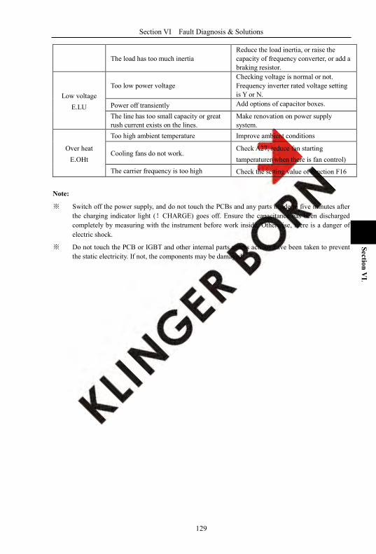
Section VI Fault Diagnosis & Solutions
129
Section VI.
The load has too much inertia Reduce the load inertia, or raise the capacity of frequency converter, or add a braking resistor.
Low voltage E.LU
Too low power voltage Checking voltage is normal or not. Frequency inverter rated voltage setting is Y or N.
Power off transiently Add options of capacitor boxes.
The line has too small capacity or great rush current exists on the lines.
Make renovation on power supply system.
Over heat E.OHt
Too high ambient temperature Improve ambient conditions
Cooling fans do not work. Check A27, reduce fan starting tamperaturer(when there is fan control)
The carrier frequency is too high Check the setting value of function F16
Note:
※ Switch off the power supply, and do not touch the PCBs and any parts inside in five minutes after the charging indicator light (!CHARGE) goes off. Ensure the capacitance has been discharged completely by measuring with the instrument before work inside. Otherwise, there is a danger of electric shock.
※ Do not touch the PCB or IGBT and other internal parts unless actions have been taken to prevent the static electricity. If not, the components may be damaged.
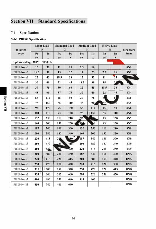
130
Section VII
Section VII Standard Specifications
7-1. Specification
7-1-1. PI8000 Specification
Inverter type
Light Load F
Standard Load G
Medium Load M
Heavy Load H Structure
item PF
kW IF
A PG
kW IG
A PM
kW IM
A PH
kW IH
A 3 phase voltage 380V 50/60Hz
PI80003 15 32 11 25 7.5 16 8N2
PI80003 18.5 38 15 32 11 25 7.5 16 8N2
PI80003 22 45 18.5 38 15 32 11 25 8N3
PI80003 30 60 22 45 18.5 38 15 32 8N3
PI80003 37 75 30 60 22 45 18.5 38 8N4
PI80003 45 90 37 75 30 60 22 45 8N4
PI80003 55 110 45 90 37 75 30 60 8N5
PI80003 75 150 55 110 45 90 37 75 8N5
PI80003 93 170 75 150 55 110 45 90 8N6
PI80003 110 210 93 170 75 150 55 110 8N6
PI80003 132 250 110 210 93 170 75 150 8N7
PI80003 160 300 132 250 110 210 93 170 8N7
PI80003 187 340 160 300 132 250 110 210 8N8
PI80003 200 380 187 340 160 300 132 250 8N8
PI80003 220 415 200 380 187 340 160 300 8N9
PI80003 250 470 220 415 200 380 187 340 8N9
PI80003 280 520 250 470 220 415 200 380 8N9
PI80003 200 380 200 380 187 340 160 300 8NA
PI80003 220 415 220 415 200 380 187 340 8NA
PI80003 250 470 250 470 220 415 220 380 8NA
PI80003 315 600 280 520 250 470 220 415 8NB
PI80003 355 640 315 600 280 520 250 470 8NB
PI80003 400 690 355 640 315 600 8NB
PI80003 450 740 400 690 8NB

Section VII Standard Specifications
131
Section VII
7-1-2. PI8100 Specification
Inverter type
Light Load F
Standard Load G
Medium Load M
Heavy Load H Structure
item PF
kW IF
A PG
kW IG
A PZ
kW IZ
A PH
kW IH
A Single phase voltage 220V 50/60Hz
PI81001 0.75 4 0.4 2.5 7N2
PI81001 1.5 7 0.75 4 0.4 2.5 7N2
PI81001 1.5 7 0.75 4 0.4 2.5 7N2
PI81001 2.2 10 2.2 10 1.5 7 0.75 4 7N3
PI81001 4 16 4 16 2.2 10 1.5 7 7N3
PI81001 5.5 20 5.5 20 4 16 2.2 10 7N4
3 phase voltage 220V 50/60Hz
PI81002 0.75 4 0.4 2.5 7N2
PI81002 1.5 7 0.75 4 0.4 2.5 7N2
PI81002 1.5 7 0.75 4 0.4 2.5 7N2
PI81002 2.2 10 2.2 10 1.5 7 0.75 4 7N3
PI81002 4 16 4 16 2.2 10 1.5 7 7N3
PI81002 5.5 20 5.5 20 4 16 2.2 10 7N4
3 phase voltage 380V 50/60Hz
PI81003 0.75 2.5 0.75 2.5 0.75 2.5 0.75 2.5 7N2
PI81003 1.5 3.7 1.5 3.7 1.5 3.7 1.5 3.7 7N2
PI81003 2.2 5 2.2 5 2.2 5 2.2 5 7N2
PI81003 4 8.5 4 8.5 4 8.5 4 8.5 7N3
PI81003 5.5 13 5.5 13 5.5 13 7N3
PI81003 7.5 16 7.5 16 7.5 16 5.5 13 7N4
PI81003 11 25 7N4
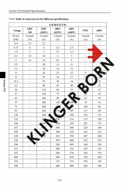
Section VII Standard Specifications
132
Section VII
7-1-3. Table of rated current for different specifications
G/F/H/S/Z/T/M
Votage 220V 1Ф
220V (240V)
380V (415V)
460V (440V)
575V 660V
Power (kW)
Current (A)
Current (A)
Current (A)
Current (A)
Current (A)
Current (A)
0.4 2.5 2.5 - - - -
0.75 4 4 2.5 2.5 - - 1.5 7 7 3.7 3.7 - - 2.2 10 10 5 5 - -
4 16 16 8.5 8 - - 5.5 - 20 13 11 - -
7.5 - 30 16 15 - - 11 - 42 25 22 17 15
15 - 55 32 27 22 18 18.5 - 70 38 34 26 22 22 - 80 45 40 33 28
30 - 110 60 55 41 35 37 - 130 75 65 52 45
45 - 160 90 80 62 52
55 - 200 110 100 76 63 75 - 260 150 130 104 86
93 - 320 170 147 117 98 110 - 380 210 180 145 121
132 - 420 250 216 173 150 160 - 550 300 259 207 175
187 - 600 340 300 230 198 200 - 660 380 328 263 218 220 - 720 415 358 287 240
250 - - 470 400 325 270 280 - - 520 449 360 330
315 - - 600 516 415 345 355 - - 640 570 430 370 400 - - 690 650 520 430 450 - - 740 700 600 490
500 - - 860 800 650 540
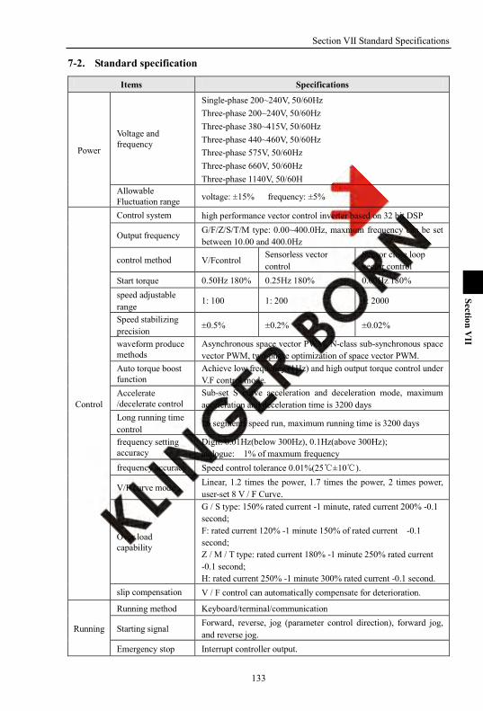
Section VII Standard Specifications
133
Section VII
7-2. Standard specification
Items Specifications
Power
Voltage and frequency
Single-phase 200~240V, 50/60Hz Three-phase 200~240V, 50/60Hz Three-phase 380~415V, 50/60Hz Three-phase 440~460V, 50/60Hz Three-phase 575V, 50/60Hz Three-phase 660V, 50/60Hz Three-phase 1140V, 50/60H
Allowable Fluctuation range voltage: ±15% frequency: ±5%
Control
Control system high performance vector control inverter based on 32 bit DSP
Output frequency G/F/Z/S/T/M type: 0.00~400.0Hz, maxmum frequency can be set between 10.00 and 400.0Hz
control method V/Fcontrol Sensorless vector control
Sensor close loop vector control
Start torque 0.50Hz 180% 0.25Hz 180% 0.00Hz 180% speed adjustable range
1: 100 1: 200 1: 2000
Speed stabilizing precision
±0.5% ±0.2% ±0.02%
waveform produce methods
Asynchronous space vector PWM, N-class sub-synchronous space vector PWM, two-phase optimization of space vector PWM.
Auto torque boost function
Achieve low frequency (1Hz) and high output torque control under V.F control mode.
Accelerate /decelerate control
Sub-set S curve acceleration and deceleration mode, maximum acceleration and deceleration time is 3200 days
Long running time control
16 segments speed run, maximum running time is 3200 days
frequency setting accuracy
Digit: 0.01Hz(below 300Hz), 0.1Hz(above 300Hz); alalogue: 1% of maxmum frequency
frequency accuracy Speed control tolerance 0.01%(25±10).
V/F curve mode Linear, 1.2 times the power, 1.7 times the power, 2 times power, user-set 8 V / F Curve.
Over load capability
G / S type: 150% rated current -1 minute, rated current 200% -0.1 second; F: rated current 120% -1 minute 150% of rated current -0.1 second; Z / M / T type: rated current 180% -1 minute 250% rated current -0.1 second; H: rated current 250% -1 minute 300% rated current -0.1 second.
slip compensation V / F control can automatically compensate for deterioration.
Running
Running method Keyboard/terminal/communication
Starting signal Forward, reverse, jog (parameter control direction), forward jog, and reverse jog.
Emergency stop Interrupt controller output.

Section VII Standard Specifications
134
Section VII
fault reset When the protection function is active, you can automatically or manually reset the fault condition.
Running status Motor status display, stop, acceleration and deceleration, constant speed, the program running.
DC brake Built-in PID regulator brake current flow in the premise, however, to ensure adequate braking torque.
Protection
Inverter protection
Overvoltage protection, undervoltage protection, overcurrent protection, overload protection, over-temperature protection, over the loss of speed protection, over-voltage stall protection, phase protection (optional), external fault, communication error, PID feedback signal abnormalities, PG failure
IGBT temperature desplay Display current IGBT temperature
Inverter fan control The fan starting temperature can be set(optional)
Instant power-down re-start
Less than 15 milliseconds: continuous operation. Greater than 15 milliseconds: Automatic detection of motor speed, instantaneous power-down re-start.
Speed starting track method
automatically track motor speed when inverter starts
Parameter protection function
Protect inverter parameters by setting the password and decoding
IO
8 way switch input Can be customized into 68 kinds of functions, to achieve forward, reverse, forward jog, and reverse jog, emergency stop, reset, speed, acceleration speed, run-time switch, and pulse counting.
3 way analog inputs Can be defined as a switch input; To allow for maximum input range-10V ~ +10V, 0 ~ 20mA
2 way anolog output
Can achieve output range 0 ~ +10V, 0 ~ 20mA
Virtual terminal function
Can be set to a virtual terminal, using communication or keyboard IO port, and with the IO port status display.
Keyboard
Frequency set In 6 main ways + to 7 kinds of auxiliary to the way of the keyboard, three way analog input, pulse input, digital potentiometers.
Keyboard cable 8-core cable, in line with EIA T568A, EIA T568B standards. Double keyboard port
Supports dual-keyboard, synchronous control, independently of each other.
Double and multi function keys
MF1, MF2 can be customized as addition and subtraction, forward, reverse, forward jog, and reverse jog, emergency stop, rise and fall, and other 9 kinds of ways.
4-parameter storages Control panel can be realized four groups of inverter parameters of upload, download, with manufacturer password to reset factory setting.
Running info At most display 3 monitoring parameters. Select by A00, A01, A02
Fault info
Store 5 groups error messages at most, you can check the type of failure time when failure occurrs, set frequency, output frequency, output voltage, output current, running state, running time, IGBT temperature.
Commu- nication
Double RS485 port Rs485 port and an optional keyboard completely isolated RS485 communication module.

Section VII Standard Specifications
135
Section VII
CAN BUS Can select can-bus module.
Speed
16-segment speed At most 16 segments can be set (use multi-functional terminal to shift or program runs).
8-segment running time
At most8segment running time can be set(multi-functional terminal can be used to shift)
8 segment acceleration speed
At most 8 acceleration speed(can use the multi-functional terminal to switch).
Seven-Segment Speed Configuration
At most 7 segment speed configuration can be set (multi-functional terminal can be used to switch).
PID PID feedback signal
Six kinds of ways, keyboard, three way analog input, pulse input, digital potentiometers.
PID giving signal Six kinds of ways, keyboard, three wayl analog input, pulse input, digital potentiometers.
Motor
2 goups of motor parameters
With the motor parameters, parameter can be selected, parameter identification automatic storage.
3 identification method
Name plate calculation, static measurement, rotation measurements.
5 name plate parameters
Rated frequency, rated current, rated voltage, the number of pole pairs, rated speed.
5 indentification parameters
N-load current, stator resistance, rotor resistance, stator inductance, mutual inductance.
Environ- ment
Environment temperature
-10 ~ 40, 40 ~ 50 derating between the use is increased by 1 , rated output current decrease of 1%.
Store temperature -40~+70 Environment humidity 5~ 95 %, No condensation
Height·vibration 0 ~ 2000 meters, 1000 meters above derating use, increased by 100 m, rated input decreased%
Application location
Mounted vertically inside the control cabinet with good ventilation, do not allow the level , or other installation method . The cooling medium is air. Installed in the absence of direct sunlight, N dust, N corrosive and explosive gas, N oil mist, N steam, N drip environment
Cooling method Forced air cooling and natural air cooling.

Section VII Standard Specifications
136
Section VII
7-3. Sharp Size
7-3-1. PI8000 family (3 phase voltage 380~415V, 50/60Hz)
1. 8N2~8N9 W
b
d
a L
H
1) 8N2
Type Power (kW)
Structure item
Shape Installation dimension
L W H a b d
F 15~18.5
8N2 380 220 230 360 135 Ø10 G 11~15
M 7.5~11
H 7.5
2) 8N3
Type Power (kW)
Structure item
Shape Installation dimension
L W H a b d
F 22~30
8N3 460 280 245 440 160 Ø10 G 18.5~22
M 15~18.5
H 11~15
3) 8N4
Type Power (kW)
Structure item
Shape Installation dimension
L W H a b d
F 37~45 8N4 500 300 270 480 200 Ø10
G 30~37

Section VII Standard Specifications
137
Section VII
M 22~30
H 18.5~22
4) 8N5
Type Power (kW)
Structure item
Shape Installation dimension
L W H a b d
F 55~75
8N5 630 360 297 610 200 Ø10 G 45~55
M 37~45
H 30~37
5) 8N6
Type Power (kW)
Structure item
Shape Installation dimension
L W H a b d
F 93~170
8N6 700 400 297 680 200 Ø10 G 75~93
M 55~75
H 45~55
6) 8N7
Type Power (kW)
Structure item
Shape Installation dimension
L W H a b d
F 132~160
8N7 750 475 320 730 260 Ø10 G 110~132
M 93~110
H 75~93
7) 8N8
Type Power (kW)
Structure item
Shape Installation dimension
L W H a b d
F 187~200
8N8 850 500 320 830 260 Ø10 G 160~187
M 132~160
H 110~132
8) 8N9
Type Power (kW)
Structure item
Shape Installation dimension
L W H a b d
F 220~250~280
8N9 1000 600 380 940 370 Ø14 G 200~220~250
M 187~200~220
H 160~187~200

Section VII Standard Specifications
138
Section VII
2. 8NA
a
Mur o d i sost egno del f o r o d i m on t aggio
Type Power (kW)
Structure item
Shape Installation dimension
L W H a b d
F 200~220~250
8NA 1540 515 443 465 367 Ø13 G 200~220~250
M 187~200~220
H 160~187~220
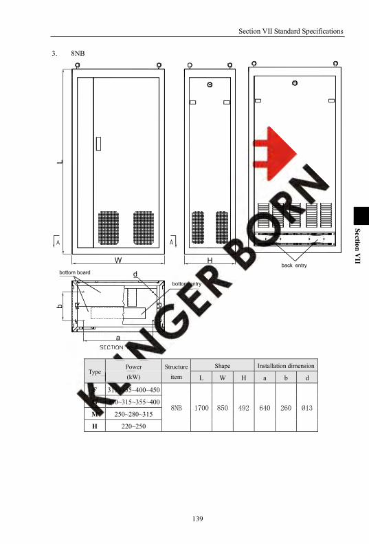
Section VII Standard Specifications
139
Section VII
3. 8NB
bottom board
bottom entry
back entryH
d
a
bL
W
Type Power (kW)
Structure item
Shape Installation dimension
L W H a b d
F 315~355~400~450
8NB 1700 850 492 640 260 Ø13 G 280~315~355~400
M 250~280~315
H 220~250

Section VII Standard Specifications
140
Section VII
7-3-2. PI8100 Family
1. 7N2~7N4
1) 7N2
PRG FWDMF2MF1
ESC STOP/RESETSET
DIGITAL PANEL
+
-
+
EN
TER
ALARM
V
A
Hz
s
%°C
-FWD REV
S00 设定频率 0.00 0.0
S01 实际频率
S10 PID反馈值
Power type Type Power (kW)
Single phase 220V
F 0.75~1.5
G 0.4~1.5
M 0.4~0.75
H 0.4
3 phase 220V
F 0.75~1.5
G 0.4~1.5
M 0.4~0.75
H 0.4
3 phase 380V
F 0.75~1.5~2.2
G 0.75~2.2
M 0.75~2.2
H 0.75~2.2

Section VII Standard Specifications
141
Section VII
2) 7N3
PRG FWDMF2MF1
ESC STOP/RESETSET
DIGITAL PANEL
+
-
+
EN
TER
ALARM
V
A
Hz
s
%°C
-
FWD REV
S00 设定频率 0.00 0.0
S01 实际频率
S10 PID反馈值
Power type Type Power (kW)
Single phase 220V
F 2.2~4
G 2.2~4
M 1.5~2.2
H 0.75~1.5
3 phase 220V
F 2.2~4
G 2.2~4
M 1.5~2.2
H 0.75~1.5
3 phase 380V
F 4~5.5
G 4~5.5
M 4~5.5
H 4
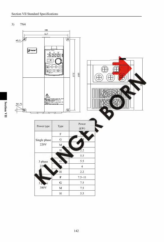
Section VII Standard Specifications
142
Section VII
3) 7N4
PRG FWDMF2MF1
ESC STOP/RESETSET
DIGITAL PANEL
+
-
+
EN
TER
ALARM
V
A
Hz
s
%°C
-
FWD REV
S00 设定频率 0.00 0.0
S01 实际频率
S10 PID反馈值
Power type Type Power (kW)
Single phase 220V
F 5.5
G 5.5
M 4
H 2.2
3 phase 220V
F 5.5
G 5.5
M 4
H 2.2
3 phase 380V
F 7.5~11
G 7.5
M 7.5
H 5.5
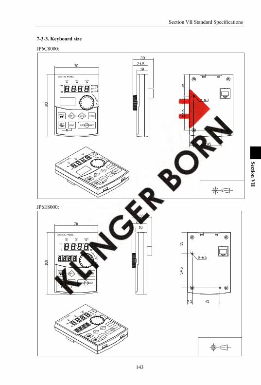
Section VII Standard Specifications
143
Section VII
7-3-3. Keyboard size
JP6C8000:
DIGITAL PANEL
FWD REV ALARM
+
-
Hz
A
V
%
s
EN
TER
PRG
ESC
MF1 MF2 FWD
SET STOP/RESET
+
-
JP6E8000:
DIGITAL PANEL
FWD REV ALARM
+
-
Hz
A
V
%
s
EN
TER
PRG
ESC
MF1 MF2 FWD
SET STOP/RESET
+
-

Section VII Standard Specifications
144
Section VII
JP6D8000 the dimension of keyboard rabbet:
the dimension of aperture for installing keyboard in panel:(75.5±0.1)*(122.5±0.1)
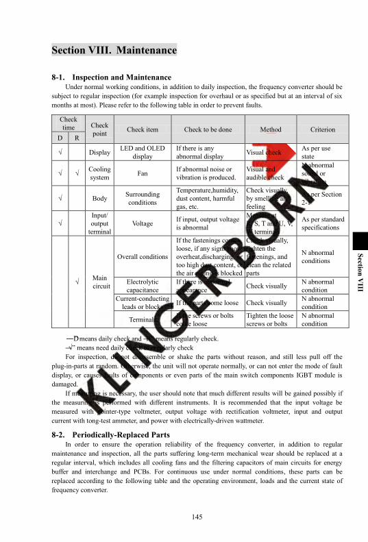
145
Section VIII
Section VIII. Maintenance
8-1. Inspection and Maintenance Under normal working conditions, in addition to daily inspection, the frequency converter should be
subject to regular inspection (for example inspection for overhaul or as specified but at an interval of six months at most). Please refer to the following table in order to prevent faults.
Check time Check
point Check item Check to be done Method Criterion D R
√ Display LED and OLED display
If there is any abnormal display Visual check As per use
state
√ √ Cooling system Fan If abnormal noise or
vibration is produced. Visual and audible check
N abnormal sound or vibration
√ Body Surrounding conditions
Temperature,humidity, dust content, harmful gas, etc.
Check visually, by smelling and feeling
As per Section 2-1
√ Input/ output
terminal Voltage If input, output voltage
is abnormal
Measure at R, S, T and U, V, W terminals
As per standard specifications
√ Main circuit
Overall conditions
If the fastenings come loose, if any signs show overheat,discharging, or too high dust content, or the air piping is blocked
Check visually, tighten the fastenings, and clean the related parts
N abnormal conditions
Electrolytic capacitance
If there is abnormal appearance Check visually N abnormal
condition Current-conducting
leads or blocks If the parts come loose Check visually N abnormal condition
Terminals If the screws or bolts come loose
Tighten the loose screws or bolts
N abnormal condition
―D‖ means daily check and ―R‖ means regularly check. ―√‖ means need daily check or regularly check For inspection, do not disassemble or shake the parts without reason, and still less pull off the
plug-in-parts at random. Otherwise, the unit will not operate normally, or can not enter the mode of fault display, or causes faults of components or even parts of the main switch components IGBT module is damaged.
If measuring is necessary, the user should note that much different results will be gained possibly if the measuring is performed with different instruments. It is recommended that the input voltage be measured with pointer-type voltmeter, output voltage with rectification voltmeter, input and output current with tong-test ammeter, and power with electrically-driven wattmeter.
8-2. Periodically-Replaced Parts In order to ensure the operation reliability of the frequency converter, in addition to regular
maintenance and inspection, all the parts suffering long-term mechanical wear should be replaced at a regular interval, which includes all cooling fans and the filtering capacitors of main circuits for energy buffer and interchange and PCBs. For continuous use under normal conditions, these parts can be replaced according to the following table and the operating environment, loads and the current state of frequency converter.
Section VIII Maintenance
146
Section IX
Part name Interval for replacement Cooling fan 1~3 years Filtering capacitor 4~5 years PCB (printed circuit board) 5~8 years
8-3. Storage The following actions must be taken if the frequency converter is not put into use immediately after
delivery to the user and need to keep well for the time being or stored for a long time: ※ Stored in a dry and adequately-ventilated place without dust and metal powder at the temperature
specified in the specifications. ※ If the frequency converter is not put into use after one year, a charge test should be made, so as to
resume the performance of the filtering capacitor of main circuit in it. For charging, a voltage regulator should be used to slowly increase the input voltage of the frequency converter until it reaches the rating, and the charge should last more than 1~2 hours. This test should be made at least once a year.
※ Don‘t perform breakdown test at random, for this test will cause shorter life of the frequency converter. The insulation test must be performed after the insulation resistance is measured with a 500-volt megaohm and this value must not be less than 4MΩ.
8-4. Measuring and Judgment ※ If the current is measured with the general instrument, imbalance will exists for the current at the
input terminal. Generally, differing by not more than 10% is normal. If it differs by 30%, inform the factory to replace the rectification bridge, or check if the error of three-phase input voltage is above 5V.
※ If the three-phase output voltage is measured with a general multi-meter, the reading is not accurate due to the interference of carrier frequency and only for reference.
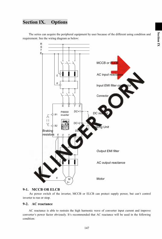
147
Section IX
Section IX. Options
The series can acquire the peripheral equipment by user because of the different using condition and requirement. See the wiring diagram as below:
9-1. MCCB OR ELCB As power switch of the inverter, MCCB or ELCB can protect supply power, but can‘t control
inverter to run or stop.
9-2. AC reactance
AC reactance is able to restrain the high harmonic wave of converter input current and improve converter‘s power factor obviously. It‘s recommended that AC reactance will be used in the following condition:
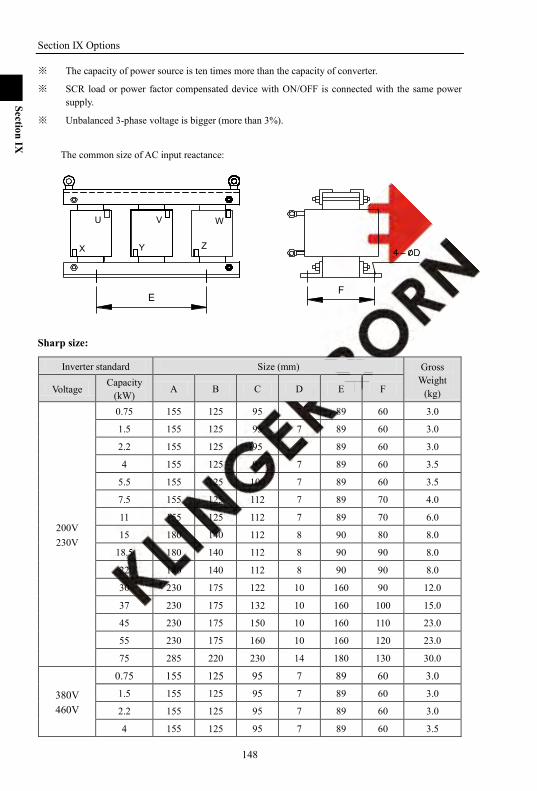
Section IX Options
148
Section IX
※ The capacity of power source is ten times more than the capacity of converter.
※ SCR load or power factor compensated device with ON/OFF is connected with the same power supply.
※ Unbalanced 3-phase voltage is bigger (more than 3%).
The common size of AC input reactance:
W
ZY
V
X
U
EF
Sharp size:
Inverter standard Size (mm) Gross Weight
(kg) Voltage Capacity
(kW) A B C D E F
200V 230V
0.75 155 125 95 7 89 60 3.0
1.5 155 125 95 7 89 60 3.0
2.2 155 125 95 7 89 60 3.0
4 155 125 95 7 89 60 3.5
5.5 155 125 100 7 89 60 3.5
7.5 155 125 112 7 89 70 4.0
11 155 125 112 7 89 70 6.0
15 180 140 112 8 90 80 8.0
18.5 180 140 112 8 90 90 8.0
22 180 140 112 8 90 90 8.0
30 230 175 122 10 160 90 12.0
37 230 175 132 10 160 100 15.0
45 230 175 150 10 160 110 23.0
55 230 175 160 10 160 120 23.0
75 285 220 230 14 180 130 30.0
380V 460V
0.75 155 125 95 7 89 60 3.0 1.5 155 125 95 7 89 60 3.0
2.2 155 125 95 7 89 60 3.0
4 155 125 95 7 89 60 3.5
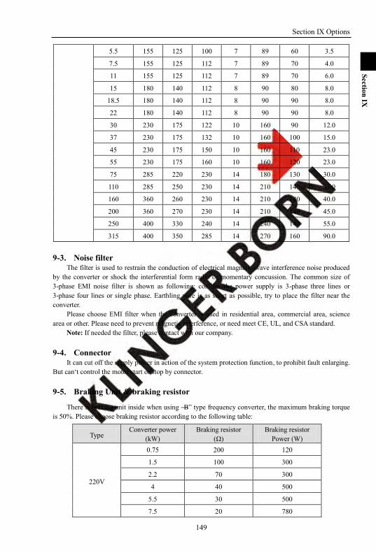
Section IX Options
149
Section IX
5.5 155 125 100 7 89 60 3.5
7.5 155 125 112 7 89 70 4.0
11 155 125 112 7 89 70 6.0
15 180 140 112 8 90 80 8.0
18.5 180 140 112 8 90 90 8.0
22 180 140 112 8 90 90 8.0
30 230 175 122 10 160 90 12.0
37 230 175 132 10 160 100 15.0
45 230 175 150 10 160 110 23.0
55 230 175 160 10 160 120 23.0
75 285 220 230 14 180 130 30.0
110 285 250 230 14 210 140 33.0
160 360 260 230 14 210 140 40.0
200 360 270 230 14 210 140 45.0
250 400 330 240 14 240 140 55.0
315 400 350 285 14 270 160 90.0
9-3. Noise filter The filter is used to restrain the conduction of electrical magnetic wave interference noise produced
by the converter or shock the interferential form radio or momentary concussion. The common size of 3-phase EMI noise filter is shown as following: confirm the power supply is 3-phase three lines or 3-phase four lines or single phase. Earthling wire is as short as possible, try to place the filter near the converter.
Please choose EMI filter when the converter is used in residential area, commercial area, science area or other. Please need to prevent magnetic interference, or need meet CE, UL, and CSA standard.
Note: If needed the filter, please contact with our company.
9-4. Connector It can cut off the supply power in action of the system protection function, to prohibit fault enlarging.
But can‘t control the motor start or stop by connector.
9-5. Braking Unit & braking resistor
There is braking unit inside when using ―B‖ type frequency converter, the maximum braking torque is 50%. Please choose braking resistor according to the following table:
Type Converter power
(kW) Braking resistor
(Ω) Braking resistor
Power (W)
220V
0.75 200 120
1.5 100 300
2.2 70 300
4 40 500
5.5 30 500
7.5 20 780
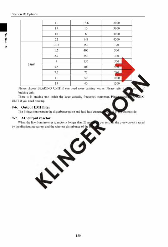
Section IX Options
150
Section IX
11 13.6 2000
15 10 3000
18 8 4000
22 6.8 4500
380V
0.75 750 120
1.5 400 300
2.2 250 300
4 150 500
5.5 100 500
7.5 75 780
11 50 1000
15 40 1500 Please choose BRAKING UNIT if you need more braking torque. Please refer to the catalog of braking unit. There is N braking unit inside the large capacity frequency converter. Please choose BRAKING
UNIT if you need braking.
9-6. Output EMI filter The fittings can restrain the disturbance noise and lead leak current produced in the output side.
9-7. AC output reactor When the line from inverter to motor is longer than 20 meters, it can restrain the over-current caused
by the distributing current and the wireless disturbance of the inverter.

151
Section X
Section X Quality Assurance
The product quality assurance is in accordance with the following regulations: 1. The manufacturer should take responsibility for below specific elements:
1-1. In domestic use (as calculated from the date of shipment) ※ shipped within one month should accept refund, replacement and repair. ※ shipped within three months should accept replacement and repair. ※ship packages within 15 months should accept repair.
1-2. Goods exported overseas (excluding China) and shipped within six months, the local seller is responsible for repair.
2. Regardless of when and where to use branded products are paid to enjoy lie-long service. 3. All the distributors, agency or production place of in whole China can provide after-sales service
for powtarn product, their conditions of service as follows: 3-1. We provide a 3-level inspection service on the local selling place (including troubleshooting). 3-2. All services comply with the related after-sale service terms and conditions stated on the
agency agreement between distributors. 3-3. Buyers can pay to any agent if need any after-sales services (whether or not the warranty).
4. If this product has some quality problem or product liability accidents, we will take the responsibility to terms 1-1 or 1-2 at most. if users need more liability guarantee, please apply for insurance company in advance to insure your own property insurance.
5. The product‘s warranty period is one year from the date of shipment. 6. In the case of the following causes of failure, even in the warranty period is also a paid repair:
6-1. Incorrect operation (depending on the use of manual), or modified without permission to repair the problems caused.
6-2. The problems caused by using the inverters beyond its standard specifications requirement. 6-3. Damage caused by drop down or improper handling. 6-4. Inverters components aged or failure caused by improper environment. 6-5. Due to an earthquake, fire, wind and water disasters, lightning, abnormal voltage or other
natural disasters and disasters, accompanied by the damage caused. 6-6. The damage during transport (Note: The mode of transport designated by the customer, the
company's help on behalf of the procedures for handling the transfer of goods). 6-7. When the manufacture‘s brand, trademark, serial number, nameplate and other damage or can
not be recognized. 6-8. If the buyer has not paid full money according to purchase agreement. 6-9. The installation, wiring, operation, maintenance or other use of objective reality can not be
described to the company's service office. 7. Concerning refund, replacement and repair services, goods shall be returned to the company, after
confirmed the attribution of responsibility then they are allowed to be returned or repaired.
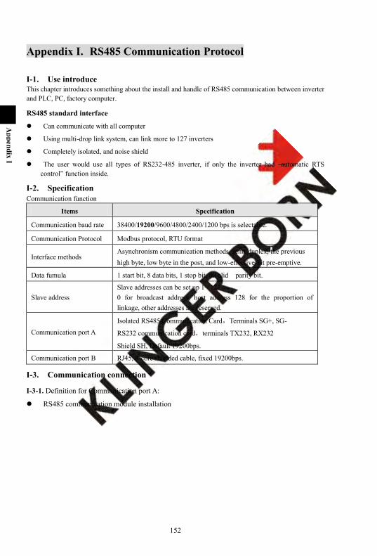
152
Appendix I
Appendix I. RS485 Communication Protocol
I-1. Use introduce This chapter introduces something about the install and handle of RS485 communication between inverter and PLC, PC, factory computer.
RS485 standard interface
Can communicate with all computer
Using multi-drop link system, can link more to 127 inverters
Completely isolated, and noise shield
The user would use all types of RS232-485 inverter, if only the inverter had ―automatic RTS control‖ function inside.
I-2. Specification Communication function
Items Specification
Communication baud rate 38400/19200/9600/4800/2400/1200 bps is selectable.
Communication Protocol Modbus protocol, RTU format
Interface methods Asynchronism communication methods, semi-duplex, the previous high byte, low byte in the post, and low-effective-bit pre-emptive.
Data fumula 1 start bit, 8 data bits, 1 stop bit, invalid parity bit.
Slave address Slave addresses can be set up 1~ 127 0 for broadcast address, host address 128 for the proportion of linkage, other addresses are reserved.
Communication port A Isolated RS485 Communication Card,Terminals SG+, SG-
RS232 communication card,terminals TX232, RX232
Shield SH, Default 19200bps.
Communication port B RJ45, 8-core shielded cable, fixed 19200bps.
I-3. Communication connection
I-3-1. Definition for Communication port A:
RS485 communication module installation
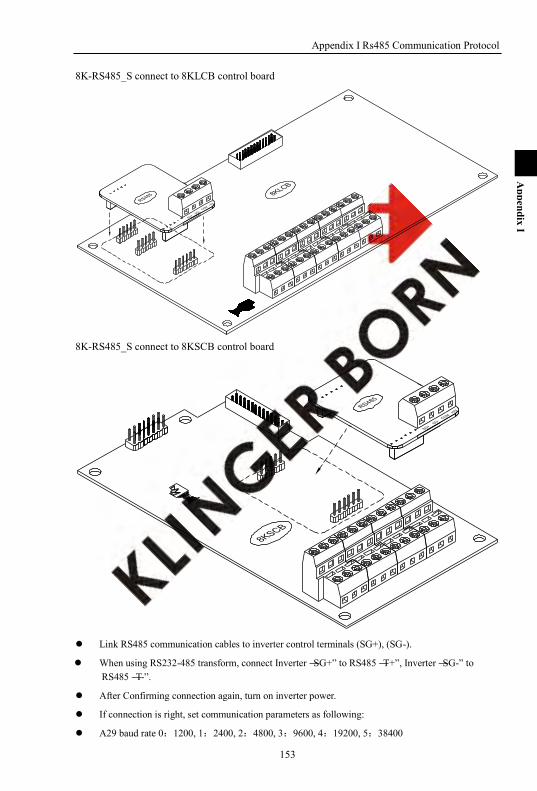
Appendix I Rs485 Communication Protocol
153
Appendix I
8K-RS485_S connect to 8KLCB control board
8K-RS485_S connect to 8KSCB control board
Link RS485 communication cables to inverter control terminals (SG+), (SG-).
When using RS232-485 transform, connect Inverter ―SG+‖ to RS485 ―T+‖, Inverter ―SG-‖ to RS485 ―T-‖.
After Confirming connection again, turn on inverter power.
If connection is right, set communication parameters as following:
A29 baud rate 0:1200, 1:2400, 2:4800, 3:9600, 4:19200, 5:38400

Appendix I Rs485 Communication Protocol
154
Appendix I
A28 current inverter communication address 1~127 (If there are more than 1 inverters, don‘t use the same number);
When using RS485 running control methods, set F04=0/1/2,choice RS485 running control method
PC
Match register120ohm 1/4W
N#2#
SG+SG-
Inverter
……1#
T-T+
GNDRXTX
RS485converter
Inverter Inverter
SG-SG+ SG-SG+
I-3-2. Definition for Communication port B:
Communication port B pins 1 2 3 4 5 6 7 8
Communication B port signal GND +5V 485+ 485- 485+ 485- +5V GND
EIA/TIA T568A White green
green White orange
blue white Blue
orange White Brown
brown
EIA/TIA T568B White Orange
Orange White Green
Blue White Blue
green White Brown
brown
I-3-3. Data safety and reliability The number of inverter can be connected is no more than 127. Though the length of communication cable can add up to 1300m, considering the stability, the length
limit within 800m. All the control signal cable use the shield cable, and is linked to the signal terminal ―SH‖ of RS485. Data packet using CRC (vertical lengthy test) frame detection to ensure data reliability. Completely isolated RS485 communication module to ensure reliable communications, support
hot-swappable, after modular access, you can enter the work. The system is tested in 6 kinds of baud rate: 0:1200, 1:2400, 2:4800, 3:9600, 4:19200, 5:38400 However, if under deteriorating environmental conditions, lowering the baud rate can improve the
communication quality. Interval time of sending from frame to frame is more than 50 bytes.
I-4. Communication Protocol
Communication architecture is inverter as a slave, the computer as a host.
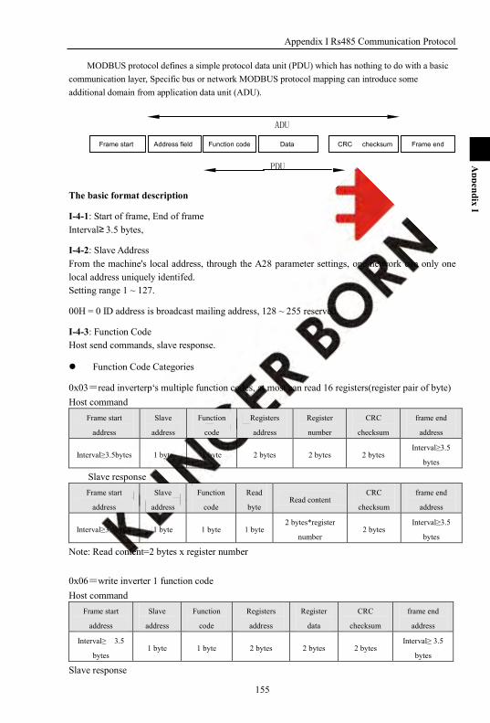
Appendix I Rs485 Communication Protocol
155
Appendix I
MODBUS protocol defines a simple protocol data unit (PDU) which has nothing to do with a basic communication layer, Specific bus or network MODBUS protocol mapping can introduce some additional domain from application data unit (ADU).
The basic format description
I-4-1: Start of frame, End of frame Interval≥ 3.5 bytes,
I-4-2: Slave Address From the machine's local address, through the A28 parameter settings, one network can only one local address uniquely identifed. Setting range 1 ~ 127.
00H = 0 ID address is broadcast mailing address, 128 ~ 255 reserved.
I-4-3: Function Code Host send commands, slave response.
Function Code Categories
0x03=read inverterp‘s multiple function codes, at most can read 16 registers(register pair of byte) Host command
Frame start
address
Slave
address
Function
code
Registers
address
Register
number
CRC
checksum
frame end
address
Interval≥3.5bytes 1 byte 1 byte 2 bytes 2 bytes 2 bytes Interval≥3.5
bytes
Slave response Frame start
address
Slave
address
Function
code
Read
byte Read content
CRC
checksum
frame end
address
Interval≥3.5bytes 1 byte 1 byte 1 byte 2 bytes*register
number 2 bytes
Interval≥3.5
bytes
Note: Read content=2 bytes x register number
0x06=write inverter 1 function code Host command
Frame start
address
Slave
address
Function
code
Registers
address
Register
data
CRC
checksum
frame end
address
Interval≥ 3.5
bytes 1 byte 1 byte 2 bytes 2 bytes 2 bytes
Interval≥ 3.5
bytes
Slave response
Frame start Frame end Address field Function code Data CRC checksum
PDU
ADU
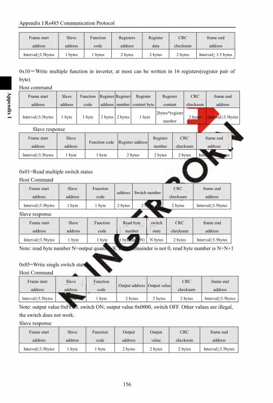
Appendix I Rs485 Communication Protocol
156
Appendix I
Frame start
address
Slave
address
Function
code
Registers
address
Register
data
CRC
checksum
frame end
address
Interval≥3.5bytes 1 bytes 1 bytes 2 bytes 2 bytes 2 bytes Interval≥ 3.5 bytes
0x10=Write multiple function in inverter, at most can be written in 16 registers(register pair of byte) Host command
Frame start
address
Slave
address
Function
code
Register
address
Register
number
Register
content byte
Register
content
CRC
checksum
frame end
address
Interval≥3.5bytes 1 byte 1 byte 2 bytes 2 bytes 1 byte 2bytes*register
number 2 bytes Interval≥3.5bytes
Slave response Frame start
address
Slave
address Function code Register address
Register
number
CRC
checksum
frame end
address
Interval≥3.5bytes 1 byte 1 byte 2 bytes 2 bytes 2 bytes Interval≥3.5bytes
0x01=Read multiple switch status Host Command
Frame start
address
Slave
address
Function
code address Switch number
CRC
checksum
frame end
address
Interval≥3.5bytes 1 byte 1 byte 2 bytes 2 bytes 2 bytes Interval≥3.5bytes
Slave response Frame start
address
Slave
address
Function
code
Read byte
number
switch
state
CRC
checksum
frame end
address
Interval≥3.5bytes 1 byte 1 byte 1 byte(data N) N bytes 2 bytes Interval≥3.5bytes
Note: read byte number N=output quanlity/8, if the remainder is not 0, read byte number is N=N+1
0x05=Write single switch status Host Command
Frame start
address
Slave
address
Function
code Output address Output value
CRC
checksum
frame end
address
Interval≥3.5bytes 1 byte 1 byte 2 bytes 2 bytes 2 bytes Interval≥3.5bytes
Note: output value 0xFF00, switch ON; output value 0x0000, switch OFF. Other values are illegal, the switch does not work. Slave response
Frame start
address
Slave
address
Function
code
Output
address
Output
value
CRC
checksum
frame end
address
Interval≥3.5bytes 1 byte 1 byte 2 bytes 2 bytes 2 bytes Interval≥3.5bytes

Appendix I Rs485 Communication Protocol
157
Appendix I
If slave response and get back to below function code, it means communications abnormal. 0xA0 =0x80+0x20= Invalid operation, setting under this state is invalid 0xA1 =0x80+0x21= function code is invalid 0xA2 =0x80+0x22= Fault record is empty 0xA3 =0x80+0x23= register address is invalid 0xA4 =0x80+0x24= slave is busy, EEPROM delay. 0xA5 =0x80+0x25= administrator restricted 0xA6 =0x80+0x26= set value is beyond limit. 0xA7 =0x80+0x27= CRC checksum error 0xA8 =0x80+0x28= frame format error
I-4-4: Register Address: The register address includes two bytes, data setting is constituted by a two-byte.
Function code Register Address high byte Register Address low byte
0x03read inverter multiple
function.code parameter
Parameter group Parameter serial number F 0x00 0~63 A 0x01 0~63 o 0x02 0~71 H 0x03 0~55 U 0x04 0~15 P 0x05 0~15 E 0x06 0~23 C 0x07 0~47 b 0x08 0~23 y NOTE 1 0x09 0~23 S 0x0B 0~15
0x03.read inverter status
Status Status number
R 0x10
0x00 Running status NOTE 2 0x01 Reserved status 1 0x02 Reserved status 2 0x03 Reserved status 3
0x03read inverter.fault history record
Fault record Fault status history record content
Fault history record 1 Fault history record 2 Fault history record 3 Fault history record 4 Fault history record 5
0x20 0x21 0x22 0x23 0x24
0x00 Fault type NOTE 4 0x01 Set frequency 0x02 Actual frequency 0x03 Actual current 0x04 DC voltage 0x05 Running status NOTE 5 0x06 Running time 0x07 IGBT temperature
0x06.write inverter.single
Register Address high byte Register Address low byte Parameter group High byte Parameter serial number
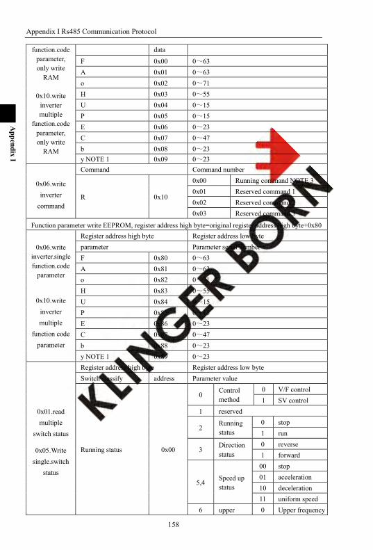
Appendix I Rs485 Communication Protocol
158
Appendix I
function.code parameter, only write
RAM
0x10.write inverter multiple
function.code parameter, only write
RAM
data
F 0x00 0~63 A 0x01 0~63 o 0x02 0~71 H 0x03 0~55 U 0x04 0~15 P 0x05 0~15 E 0x06 0~23 C 0x07 0~47 b 0x08 0~23 y NOTE 1 0x09 0~23
0x06.write inverter
command
Command Command number
R 0x10
0x00 Running command NOTE 3 0x01 Reserved command 1 0x02 Reserved command 2 0x03 Reserved command 3
Function parameter write EEPROM, register address high byte=original register address high byte+0x80
0x06.write inverter.single function.code
parameter
0x10.write inverter multiple
function code parameter
Register address high byte Register address low byte parameter Parameter serial number F 0x80 0~63 A 0x81 0~63 o 0x82 0~71 H 0x83 0~55 U 0x84 0~15 P 0x85 0~15 E 0x86 0~23 C 0x87 0~47 b 0x88 0~23 y NOTE 1 0x89 0~23
0x01.read multiple
switch status
0x05.Write single.switch
status
Register address high byte Register address low byte Switch classify address Parameter value
Running status 0x00
0 Control method
0 V/F control 1 SV control
1 reserved
2 Running status
0 stop 1 run
3 Direction status
0 reverse 1 forward
5,4 Speed up status
00 stop 01 acceleration 10 deceleration 11 uniform speed
6 upper 0 Upper frequency
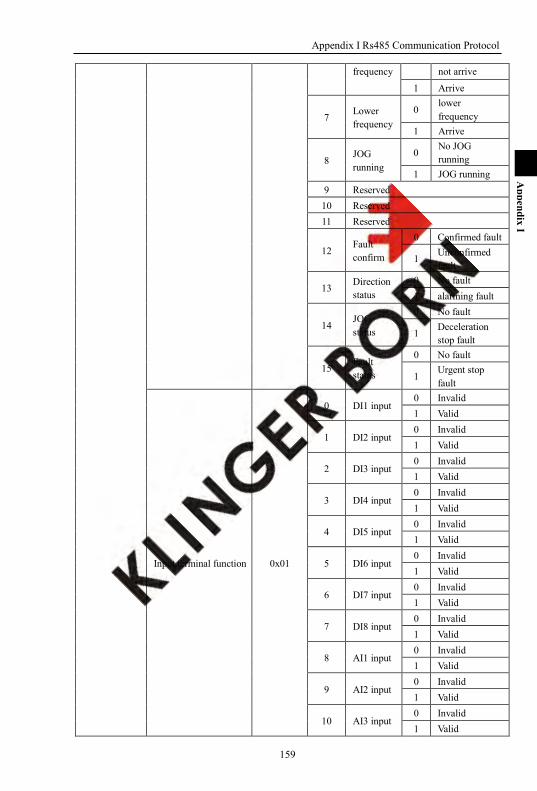
Appendix I Rs485 Communication Protocol
159
Appendix I
frequency not arrive
1 Arrive
7 Lower frequency
0 lower frequency
1 Arrive
8 JOG running
0 No JOG running
1 JOG running 9 Reserved
10 Reserved 11 Reserved
12 Fault confirm
0 Confirmed fault
1 Unconfirmed fault
13 Direction status
0 No fault 1 alarming fault
14 JOG status
0 No fault
1 Deceleration stop fault
15 Fault status
0 No fault
1 Urgent stop fault
Input.terminal function 0x01
0 DI1 input 0 Invalid 1 Valid
1 DI2 input 0 Invalid 1 Valid
2 DI3 input 0 Invalid 1 Valid
3 DI4 input 0 Invalid 1 Valid
4 DI5 input 0 Invalid 1 Valid
5 DI6 input 0 Invalid 1 Valid
6 DI7 input 0 Invalid 1 Valid
7 DI8 input 0 Invalid 1 Valid
8 AI1 input 0 Invalid 1 Valid
9 AI2 input 0 Invalid 1 Valid
10 AI3 input 0 Invalid 1 Valid
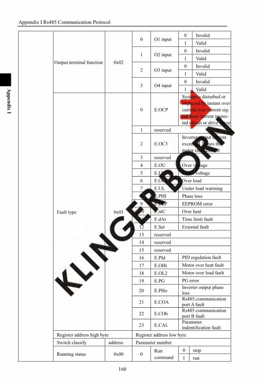
Appendix I Rs485 Communication Protocol
160
Appendix I
Output.terminal function 0x02
0 O1 input 0 Invalid 1 Valid
1 O2 input 0 Invalid 1 Valid
2 O3 input 0 Invalid 1 Valid
3 O4 input 0 Invalid 1 Valid
Fault type 0x03
0 E.OCP
System is disturbed or impacted by instant over current,over current sig- nal from current inspec- ted circuit or drive circuit
1 reserved
2 E.OC3 Inverter output current exceeded 3times the motor rated current
3 reserved 4 E.OU Over voltage 5 E.LU Under voltage 6 E.OL Over load 7 E.UL Under load warming 8 E.PHI Phase loss 9 E.EEP EEPROM error
10 E.ntC Over heat 11 E.dAt Time limit fault 12 E.Set External fault 13 reserved 14 reserved 15 reserved 16 E.PId PID regulation fault
17 E.OHt Motor over heat fault
18 E.OL2 Motor over load fault
19 E.PG PG error
20 E.PHo Inverter output phase loss
21 E.COA Rs485.communication port A fault
22 E.COb Rs485.communication port B fault
23 E.CAL Parameter indentification fault
Register address high byte Register address low byte Switch classify address Parameter number
Running status 0x00 0 Run command
0 stop 1 run
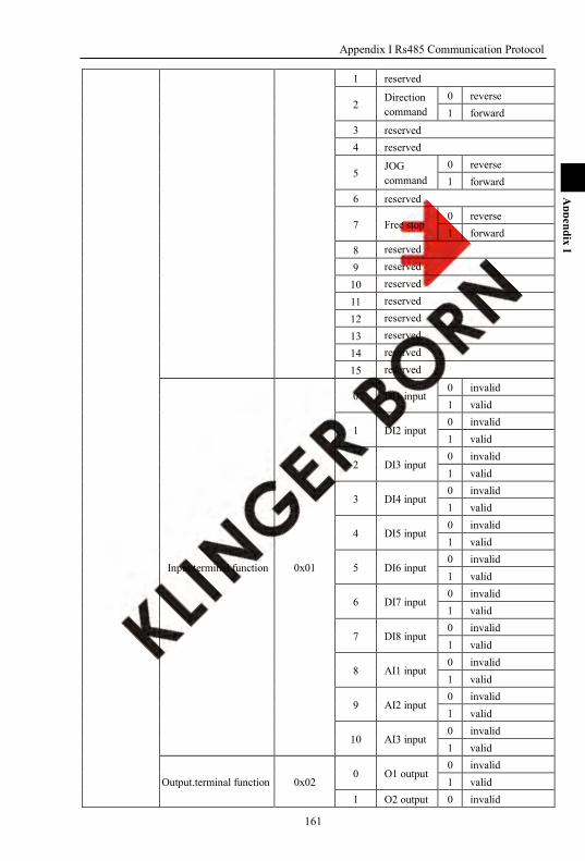
Appendix I Rs485 Communication Protocol
161
Appendix I
1 reserved
2 Direction command
0 reverse 1 forward
3 reserved 4 reserved
5 JOG command
0 reverse 1 forward
6 reserved
7 Free stop 0 reverse 1 forward
8 reserved
9 reserved
10 reserved
11 reserved
12 reserved
13 reserved
14 reserved
15 reserved
Input.terminal function 0x01
0 DI1 input 0 invalid 1 valid
1 DI2 input 0 invalid 1 valid
2 DI3 input 0 invalid 1 valid
3 DI4 input 0 invalid 1 valid
4 DI5 input 0 invalid 1 valid
5 DI6 input 0 invalid 1 valid
6 DI7 input 0 invalid 1 valid
7 DI8 input 0 invalid 1 valid
8 AI1 input 0 invalid 1 valid
9 AI2 input 0 invalid 1 valid
10 AI3 input 0 invalid 1 valid
Output.terminal function 0x02 0 O1 output
0 invalid 1 valid
1 O2 output 0 invalid
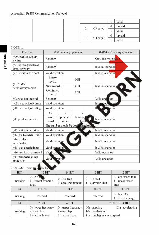
Appendix I Rs485 Communication Protocol
162
Appendix I
1 valid
2 O3 output 0 invalid 1 valid
3 O4 output 0 invalid 1 valid
NOTE 1: Function 0x03 reading operation 0x06/0x10 writing operation
y00 reset the factory setting
Return 0 Only can write into 5
y01 upload parameter onto keyboard
Return 0 Invalid operation
y02 latest fault record Valid operation Invalid operation
y03~y07 fault history record
Empty record 00H
Invalid operation New record 01H Confirmed
record 02H
y08reset fault record Return 0 Valid operation y09 rated output current Valid operation Invalid operation y10 rated output voltage Valid operation Invalid operation
y11 products series
80 0 3
Invalid operation Family serial
products series
Input voltage level
The number should be decimalization. y12 soft ware version Valid operation Invalid operation y13 product date –year Valid operation Invalid operation y14 product month–date
Valid operation Invalid operation
y15 user decode input Valid operation Invalid operation y16 user input password Valid operation Valid operation y17 parameter group protection
Valid operation Valid operation
NOTE 2: running status byte BIT 15 BIT 14 BIT 13 BIT 12 BIT
meaning 0:No fault 1:urgent stopping fault
0:No fault 1:decelerating fault
0:No fault 1:alarming fault
0:confirmed fault 1:unconfirmed fault
bit 11 BIT 10 BIT、 9 BIT 8 BIT
meaning reserved reserved reserved 0:No JOG. 1:JOG running
bit 7 BIT 6 BIT 5 BIT 、 4 BIT
meaning 0:lower frequency not arriving 1:arrive lower
0:upper frequency not arriving 1:arrive upper
00:stopping 01:accelerating 10:decelerating 11:running in a even speed

Appendix I Rs485 Communication Protocol
163
Appendix I
frequency frequency
bit 3 BIT 2 BIT 1 BIT 0 BIT
meaning 0:running reverse 1:running forward
0: stopping 1: running reserve
0: V/F control 1:SV control
NOTE 3:running command bit 15 BIT 14 BIT 13 BIT 12 BIT
meaning reserve reserve reserve reserve
Bit 11 BIT 10 BIT 9 BIT 8 BIT
meaning reserve reserve reserve reserve
bit 7 BIT 6 BIT 5 BIT 4 BIT
meaning 0:No free-stop 1:free-stop command
reserve 0:JOG stopping 1:JOG running
reserve
bit 3 BIT 2 BIT 1 BIT 0 BIT
meaning reserve 0:reverse command 1:forward command
reserve 0:stop command 1:run command
NOTE 4:fault style code
Serial.number LED display Fault message
0 E.OCP System is disturbed or impacted by instant over current, over current signal from current inspected circuit or drive circuit
1 reserve
2 E.OC3 Inverter output current exceeded 3 times of motor rated current
3 reserve
4 E.OU Over voltage
5 E.LU Under voltage
6 E.OL Over load
7 E.UL Under load warm
8 E.PHI Input phase loss
9 E.EEP EEPROM error
10 E.ntC Over heat
11 E.dAt Time limit fault
12 E.Set External fault
13 reserve
14 reserve
15 reserve
16 E.PId PID regulation fault
17 E.OHt Motor over heat fault

Appendix I Rs485 Communication Protocol
164
Appendix I
18 E.OL2 Motor over load fault
19 E.PG PG error
20 E.PHo Inverter output loss phase
21 E.COA Rs485 communication port A fault
22 E.COb Rs485 communication port B fault
23 E.CAL Parameter indentification fault
NOTE 5: fault funning status
LED first position LED second position LED third position LED fourth position
Bit15-Bit12 Bit11-Bit8 Bit7-Bit4 Bit3-Bit0
F 0 Forward
command F 0 Forward status
- 0 Separative sign
A 1 Accelerating
running R 1 Reverse
command R 1 Reverse status D 2 Decelerating
running S 2 Stop command S 2 Stop status
E 3 running in a even
speed S 0 stop
E.g. keyboard display FF-A(return data 0001),said when fault occurs the inverter state:forward command、forward
state、accelerating running
I-4-5:CRC checkup sum
Data meaning:data frame CRC checkup sum, using 2 bytes. Checkup sum = address + function code + data
Enclose:CRC computation program:
Unsigned int cal_crc16 (unsigned char *data, unsigned int length)
unsigned int i,crc_result=0xffff;
while(length--)
crc_result^=*data++;
for(i=0;i<8;i++)
if(crc_result&0x01)
crc_result=(crc_result>>1)^0xa001;
else
crc_result=crc_result>>1;
crc_result=((crc_result&0xff)<<8)|(crc_result>>8);
return(crc_result);
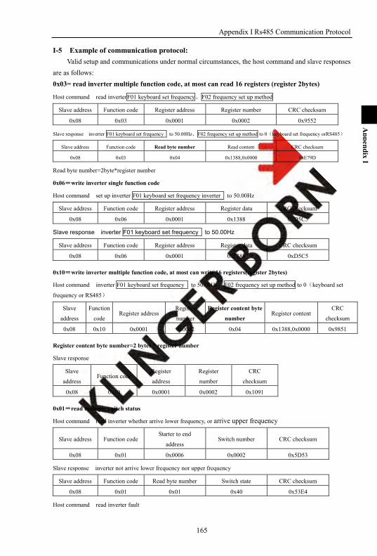
Appendix I Rs485 Communication Protocol
165
Appendix I
I-5 Example of communication protocol: Valid setup and communications under normal circumstances, the host command and slave responses
are as follows: 0x03= read inverter multiple function code, at most can read 16 registers (register 2bytes)
Host command read inverterF01 keyboard set frequency、F02 frequency set up method
Slave address Function code Register address Register number CRC checksum
0x08 0x03 0x0001 0x0002 0x9552
Slave response inverter F01 keyboard set frequency to 50.00Hz、F02 frequency set up method to 0(keyboard set frequency orRS485)
Slave address Function code Read byte number Read content CRC checksum
0x08 0x03 0x04 0x1388,0x0000 0xE79D
Read byte number=2byte*register number
0x06=write inverter single function code
Host command set up inverter F01 keyboard set frequency inverter to 50.00Hz
Slave address Function code Register address Register data CRC checksum
0x08 0x06 0x0001 0x1388 0xD5C5
Slave response inverter F01 keyboard set frequency to 50.00Hz
Slave address Function code Register address Register data CRC checksum
0x08 0x06 0x0001 0x1388 0xD5C5
0x10=write inverter multiple function code, at most can write 16 registers(register 2bytes)
Host command inverter F01 keyboard set frequency to 50.00Hz、F02 frequency set up method to 0(keyboard set
frequency or RS485)
Slave
address
Function
code Register address
Register
number
Register content byte
number Register content
CRC
checksum
0x08 0x10 0x0001 0x0002 0x04 0x1388,0x0000 0x9851
Register content byte number=2 bytes * register number
Slave response
Slave
address Function code
Register
address
Register
number
CRC
checksum
0x08 0x10 0x0001 0x0002 0x1091
0x01=read multiple switch status
Host command read inverter whether arrive lower frequency, or arrive upper frequency
Slave address Function code Starter to end
address Switch number CRC checksum
0x08 0x01 0x0006 0x0002 0x5D53
Slave response inverter not arrive lower frequency nor upper frequency
Slave address Function code Read byte number Switch state CRC checksum
0x08 0x01 0x01 0x40 0x53E4
Host command read inverter fault

Appendix I Rs485 Communication Protocol
166
Appendix I
Slave address Function code Starter to end
address Switch number CRC checksum
0x08 0x01 0x0300 0x0020 0x3D0F
Salve response inverter low voltage (E.LU switch address 0x0305)
Slave address Function code Read byte number Switch state CRC checksum
0x08 0x01 0x04 0x20,0x00,0x00,0x00 0x6911
Note :return byte :4 bytes;
Return date in order:bit7-bit0, bit15-bit8, bit23-bit16, bit31-bit24
0x05=write single switch status
Host command control inverter running
Slave address Function code Output address Output value CRC checksum
0x08 0x05 0x0000 0xFF00 0x8CA3
Slave response
Slave address Function code Output address Output value CRC checksum
0x08 0x05 0x0000 0xFF00 0x8CA3
Host command control inverter stop
Slave address Function code Output address Output value CRC checksum
0x08 0x05 0x0000 0x0000 0xCD53
Slave response
Slave address Function code Output address Output value CRC checksum
0x08 0x05 0x0000 0x0000 0xCD53
Note: set switch to 1,output value is 0xFF00;set switch to 0,output value is 0x0000.

167
Appendix II
Appendix II Instruction of the Proportional Linkage Function
II-1. proportional linkage function:
The proportion interaction host computer: Communication address = 128, Communications port A is the communication port of host computer. Communication port B can be used as the keyboard interface, or a PC host computer interface. There is only one host inverter in one proportional linkage. The host inverter control the running state, the slave inverter follow the host‘s running state.
The proportion interaction slave computer: Communication Address = 1 ~ 127, Both communication port A and communication port B can be the communication port of slave
inverter. In the slave inverter follow the host running and it can realize forced stopping by terminal or keyboard
if need.
For this function, the host computer should be set with the following parameters: A28 Local communication address 128
For this function, the slave computer should be set with the following parameters: F01 Keyboard set the frequency / Rs485 Command from proportion linkage Host
F02 Frequency main set mode
Keyboard setting frequency or RS485 0
AI1 the external analog setting 1
AI2 the external analog setting 2
AI3 the external analog setting 3
Keyboard potentiometer setting 4
Multi-segment digital voltage set 5
Digital Pulse Setting 6
F03 Auxiliary setting mode of frequency set
Keyboard setting frequency or RS485 0
AI1 the external analog setting 1
AI2 the external analog setting 2
AI3 the external analog setting 3
Keyboard potentiometer setting 4
Multi-segment digital voltage setting 5
Digital Pulse Set 6
PID regulation mode 7
F04 relationship between main and auxiliary frequencies
The main setting individual control 0
The auxiliary setting individual control 1
main + auxiliary 2
main -auxiliary 3

Appendix II Instruction of the Proportional Linkage Function
168
Appendix II
(main *auxiliary)/maximum frequency 4
Maximum{main, auxiliary} 5
Minimum{main, auxiliary} 6
F05 Running control mode Proportional linkage control 4 Select this function, the slave inverter will follow the command of host inverter to run. After select this function, it can also use keyboard, terminal and RS485 to control the
slave inverter‘s running. In the proportion of linkage during operation, if control by the keyboard, terminal,RS485
control, once the slave inverter stopped, the slave will N longer respond to the host command, if need the slave once again to respond to host commands, it should control through the keyboard, terminal and RS485, or after the host sends cease and desist commands then the slave will respond the command again to run. A28 communication address 1~127
A29 Baud rate Same as host
A30 Communication format Same as host
A55 Proportional linkage factor 0.10~10.00 During the proportional of linkage, the running state of slave inverter is controlled by the host
inverter. Slave inverter F01 = proportional factor*the actual set frequency of host inverter of proportion
linkage. Slaver S00 actual set frequency = slave F01 + frequency give and secondary amend +ascend/descend
adjusting.
II-2. Proportion linkage application Cases:
Features of proportional function: 1: the host inverter using the potentiometer to control the system speed and use the terminals to
control the forward/reverse running. 2: the slave follows the host running, the proportional linkage factor is 1.00 3: after get the running speed command from host inverter, the slave will store this command into to
F01. 4: the slave actual frequency is set through the keyboard or through terminal ascend/descend
adjusting. 5: the slave actual frequency is set through potentiometer adjusting. 6: the slave actual frequency = F01 + slave potentiometer adjusting + A40
The proportional linkage host settings: F02 Frequency main set mode AI1 external analog setting
A28 Communication address Host 128 11 A29 Baud rate 3: 9600bps
A30 Communication format 0
o36 DI1 input terminal function select selectio
1:forward running
o37 DI2 input terminal function select
2:reverse running
The proportional linkage slave settings: F02 Frequency main set keyboard set the frequency or Rs485 0
F03 Auxiliary setting mode of AI1 external analog setting 1
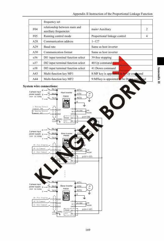
Appendix II Instruction of the Proportional Linkage Function
169
Appendix II
frequency set
F04 relationship between main and auxiliary frequencies
main+Auxiliary 2
F05 Running control mode Proportional linkage control 4
A28 Communication address 1~127
A29 Baud rate Same as host inverter
A30 Communication format Same as host inverter
o36 DI1 input terminal function select 39:free stopping
o37 DI2 input terminal function select 40:Up command
o38 DI3 input terminal function select 41:Down command
A43 Multi-function key MF1 8:MF key is appointed to be Up command
A44 Multi-function key MF2 9:MFkey is appointed to be Down command
System wire connections:
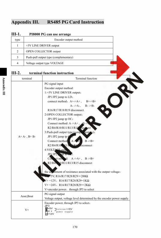
170
Appendix III
Appendix III. RS485 PG Card Instruction
III-1. PI8000 PG can use arrange type Encoder output method
1 +5V LINE DRIVER output
2 OPEN COLLECTOR output
3 Push-pull output type (complementary)
4 Voltage output type VOLTAGE
III-2. terminal function instruction terminal Terminal function
A+ A- , B+ B-
PG signal input Encoder output method: 1:+5V LINE DRIVER output;
JP1/JP2 jump to LD; connect method:A+->A+ , B+->B+
A- ->A-, B- ->B- R16/R17/R18/R19 disconnect.
2:OPEN COLLECTOR output; JP1/JP2 jump tp OC; Connect method: A ->A+ , B ->B+ R2/R4/R10/R11/R13/R15 disconect
3:Push-pull output type (complementary); JP1/JP2 jump tp OC; Connect method: A ->A+ , B ->B+ R2/R4/R10/R11/R13/R15 disconnect
4:VOLTAGE output; JP1/JP2 jump to OC; Connect method: A ->A+ , B ->B+ R2/R4/R10/R11/R13/R15 disconnect
the adjustment of resistance associated with the output voltage: V+ =5V, R16/R17/R28/R29=200Ω V+ =12V,R16/R17/R28/R29=1KΩ V+ =24V,R16/R17/R28/R29=2KΩ V+encoder power,through JP3 to select
Aout,Bout PG signal output Voltage output, voltage level determined by the encoder power supply
V+
Encoder power, through JP3 to select:

Appendix II Instruction of the Proportional Linkage Function
171
Appendix II
PGND encoder
Encoder PG pulses range 300~9999 maximum pulses frequency receiver 1MHz,when PG pulses=2500,maximum speed=400Hz
III-3. terminal connection:
Earthing(Motor)
Earthing(Power)
DC-DC+1 DC+2
DC ReactorBrake Unit
Optional
P18000 PG
V+
V-
A+
A-
B+
B-
PG
Earthing
Bout
Aout
B-
B+
A-
A+
PGND
V+
PI8000Inverter
MCCB Motor
3~M
W(T3)V(T2)U(T1)R(L1)
S(L2)T(L3)T
SR
Bout
Aout

172
Appendi IV
Appendix IV Converter Water Supply Controller Instruction
number E00 function Parameter setting definition Reference page
1 Special power supply
8 Inverter power 172
13 Stable voltage power
172
14 Constant current power
-
2 Constant pressure water supply
9 Pump constant pressure water supply
173
3 Extruding machine
15 Extruding machine
-
IV-1. Extend functions supplement
IV-1-1. E00=8: variable frequency power P03 PID given signal selection, you can set through the keyboard, analog AI1, pulse and other means
to set a given voltage. Given voltage is calculated as follows: Given voltage:220VAC Given voltage setting =220*1.414/500*100%=62.2%
Frequency Power specific parameters:
No. name scope unit meanings Factory setting
E16 User parameter 1 0~9999 - Voltage increasing time 0
E17 User parameter 2 0~9999 - Voltage decreasing time 0 In regulated power supply mode, the output and input voltage are both adjustable. The increasing time and decreasing time of output voltage is adjusted by F09 and F10. E16 is the voltage increasing time, the definition of the output voltage increasing time is from9999
corresponds to 999.9 seconds. E17 is the voltage decreasing time, the definition of the output voltage decreasing time is from9999
corresponds to 999.9 seconds. Voltage increasing/decreasing time just used to adjust the accelerate/decelerate time of output
frequency when the inverter running. After the stopping command issued, the controller will stop the frequency output when the output
frequency decelerate to 0hz. E18 User parameter 3 0~9999 - The max output voltage 0
For safety and reliability to ensure that the output voltage to bear the load within the system, we need to define the maximum output voltage of the system.
If the system highest withstand voltage 250VAC,then a maximum outout voltage= 250; E18=250。
IV-1-2. E00=13: Voltage regulation power In this mode,connect AI2,AI3 to Hall,then measure the output voltage and use2Halls to do redundant
work to ensure the output voltage will not exceed the Hall voltage limitation. In this mode, the following parameters should be adjusted:
Appendix IX Converter Water Supply Controller Instruction
173
Appendix IV
PID function group, P02 PID feedback signal selection. AI2 is detected by analog and AI3 works as a redundant configuration to ensure the output voltage
safe and reliable. When Feedback voltage is 100%, the corresponding Hall voltage is 500VAC, Hall output voltage is
5V. Set o03=50%, o05=50%. P03 PID given signal selection, you can set through the keyboard, analog AI1, pulse and other means
to set a given voltage. Given voltage is calculates as follows: When the given voltage =220VAC, given voltage setting =220*1.414/500*100%=62.2% Other PID parameters are adjusted according to the site. Under PID regulated power supply mode, the voltage acceleration and deceleration time is
controlled by PID parameters, it won‘t affect by voltage acceleration and deceleration time. Voltage regulation power specific parameters:
No. name Range unit Description Factory setting
E16 User parameter 1 0~9999 - Voltage increasing time 0
E17 User parameter 2 0~9999 - Voltage decreasing time 0 In Voltage regulation power mode, the output and input voltage are both adjustable. The increasing time and decreasing time of output voltage is adjusted by F09 and F10. E16 is the voltage increasing time, the definition of the output voltage increasing time is from 9999
corresponds to 999.9 seconds. E17 is the voltage decreasing time, the definition of the output voltage decreasing time is from
9999 corresponds to 999.9 seconds. Voltage increasing/decreasing time just used to adjust the accelerate/decelerate time of output
frequency when the inverter running. After the stopping command sent, the controller will stop the frequency output when the output
frequency decelerate to 0 hz. E18 User parameter 3 0~9999 - Max output voltage 0
For safety and reliability to ensure that the output voltage to bear the load within system,we need to define the maximum output voltage of the system.
If the System highest withstand voltage 250VAC; Then E18=250VAC.
IV-1-3. Converter water supply controller instruction
IV-2-1. Constant water supply system parameters:
(1) loading types with constant water supply function:
Parameter Keyboard display setting Meaning
E00 Load type 9
E12 set to be single pump,no need the constant pressure water supply interface board E12 set to multi-pump,need constant pressure water supply interface board,while realize 4-pumps constant pressure water supply function.
(2) PID adjusting in constant water supply system
Parameter Keyboard Display Setting Meanings
F01 Keyboard set frequency 0 Keyboard set the frequency 0hz
Appendix IX Converter Water Supply Controller Instruction
174
Appendix IV
F02 Frequency main set mode 0 Keyboard set frequency or RS485 set frequency.
F03 Frequency auxiliary set mode 7 PID adjusting mode
F04 main and auxiliary frequencies set 2 main+ auxiliary set mode
P00 PID configure 0000 single-way,the negative regulator, failure is not action
P02 Feedback signal select 1~3 External analog feedback signal given by the AI1 / AI2 / AI3
P03 Given signal select 0~6 Given signal can select the keyboard/Rs485,potentiometers, digital voltage, digital pulse, etc.
P05 PID integration time Setting according the site.
P06 PID differential time Setting according the site.
P07 PID proportional gain Setting according the site.
P09 Deviation Limit Setting according the site.
P12 PID Display Range Setting according the site.
(3) Constant pressure water supply special parameters
Parameter Keyboard Display Setting Meanings
E01 Starting pressure deviation 10% Starting pressure deviation is 10%
E02 Starting time delay 2.0 Starting delay time is second.
E03 Stop frequency 15.00 stop at frequency 15HZ.
E04 stop time delay 2.0 Stop time is 2 second.
E05 High pressure arrival value 80% feedback pressure reach and exceed the value of this parameter, the I / O output terminal select 25, then it will output arrival signal.
E06 Low pressure arrival 60%
when feedback pressure less than the low pressure reached value of this parameter, the I / O output terminal select 26, then it will output arrival signal.
E07 Timing to water supply 0000 Timing to water supply function invalid (4) Multi-function constant pressure water supply pump specific parameters
Parameter Keyboard Display Setting Meaning
E08 Timing shift alternation time 0.25 According to first start first stop principles to con - - trol pump rotation,rotation time of 0.25 hours
E09 electromagnetic switching action delay
0.500
When set up a station pump (drive motor) to switch from variable frequency industry frequ - ency, or from industry frequency to variable frequency, and set its electromagnetic switching action delay time is 0.5 seconds.
E10 Pumps shift judging time 100
To set the determine time 100 seconds from inv - erter output frequency reaches the upper limit frequencies until increase pump (drive mo - tor); or from inverter output frequency reaches the lower limit frequencies until decrease pump (drive motor).
Appendix IX Converter Water Supply Controller Instruction
175
Appendix IV
E11 Constant Pressure Water Supply Configuration
0000
Decelerating stop: When the inverter failure, the rotation switching way is from variable freque - ncy pump to industry frequency and the pump maintain the status.
E12 Multi-pump configuration 1111 N. 1 ~ 4 pumps are frequency controlled pump
E13 Multi-pumps status Multi-pump control mode, displays the status of each pump
E14 Soft-start Pump Control 0000 Multi-pump control mode, set the control mode of each pump, currently set to Full Stop
(5) constant pressure water supply IO parameter:
Parameter Keyboard Display Setting Meanings
o21~o24 Output signal select 25 High pressure arrival
o21~o24 Output signal select 26 Low pressure arrival
o36~o46 Input terminal function select 51 Pump 1 soft start
o36~o46 Input terminal function select 52 Pump 1 stop
o36~o46 Input terminal function select 53 Pump 2 soft starter
o36~o46 Input terminal function select 54 Pump 2 stop
o36~o46 Input terminal function select 55 Pump 3 soft starter
o36~o46 Input terminal function select 56 Pump 3 stop
o36~o46 Input terminal function select 57 Pump 4 soft state
o36~o46 Input terminal function select 58 Pump 4 stop
o36~o46 Input terminal function select 59 Manual shift command
o36~o46 Input terminal function select 60 Timing of water supply time-zero
IV-2-2. Application It is special appendix for multiple pumps, which run with PI7000 family inverter to control the
multiple pumps water supply system effectively.
IV-2-3. Operation and connection notice:
If it is power frequency motor, probable thermal relay must be used to protect motor.
AC contactor with machinery chain equipment should be used between the power frequency bypass and inverter output of aside the motor, lock logically on the electri control circuit to avoid the short circuit of the power frequency and inverter output which damage the inverter and equipments.
The phase order of the power frequency to the motor should be the same with the phase order of the inverter output to avoid the motor reverse. Please confirm the phase order and operate.
When wiring the control signal of the inverter, please leave it away with the driving line, and do not make them in the same wire, otherwise it will lead wrong action.
Screen cable is used for Pressure set signal and pressure feedback signal.
IV-2-4. Dimension
(1) Dimension of water supply control card
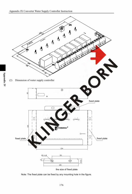
Appendix IX Converter Water Supply Controller Instruction
176
Appendix IV
(2) Dimension of water supply controller
fixed plate fixed plate
fixed plate
×
the size of fixed plate
Note: The fixed plate can be fixed by any mounting hole in the figure.

Appendix IX Converter Water Supply Controller Instruction
177
Appendix IV
IV-2-5. IV-2-5. Frequency of water supply connection to the drive controller
Connection of water supply controller with inverter, the communniction cable and power cable are connected as below:

Appendix IX Converter Water Supply Controller Instruction
178
Appendix IV
IV-2-6. System diagram
Remarks: ZK air switch KM contactor JR thermo-relay M motor
IV-2-7. Water supply control mode When several pumps supply water meanwhile, because of the different time(daytime and night),
different season(winter and summer), the variation of the water flow is great. To save energy and protect the equipment, please run pumps as many as you need and stop pumps as many as you do not need.
Inverter will confirm the number of the running pumps according to the requirement of the pressure close loop control. In the set range, only one pump is controlled by the inverter at the same time.
If the timing shift interval time is set 0.05~100.00, when the related running time is stable, inverter inverter will shift up the pumps according to stop first or open first to ensure each pump has the chance to run and avoid the pump rusted because of long time N use.
After the pumps run to the upper and lower, arrive the adding pumps or reducing pumps time, inverter will add or redcue the pumps according to stop first or open first to ensure each pump can run and avoid the pump rusted because of long time N use.
IV-2-8. Soft-start pump control mode Set the soft start pump by E12 and through the input terminals o36 ~ o46, respectively controlled
soft-start pump start and stop. Soft-start pump terminal control, stop first. Soft-start pump is not controlled by constant pressure water supply system.Soft-start pump can be
used as sewage pumps and fire pumps.
IV-2-9. Application Guide
3 Pumps constant pressure water supply + sewage pump
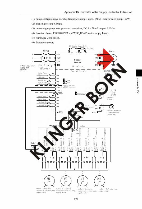
Appendix IX Converter Water Supply Controller Instruction
179
Appendix IV
(1) pump configurations: variable frequency pump 3 units, 15kW,1 unit sewage pump,15kW.
(2) The set pressure 0.8Mpa.
(3) pressure gauge options: pressure transmitter, DC 4 ~ 20mA output, 1.6Mpa.
(4) Inverter choice: PI8000 015F3 and WSC_RS485 water supply board.
(5) Hardware Connection.
(6) Parameter setting
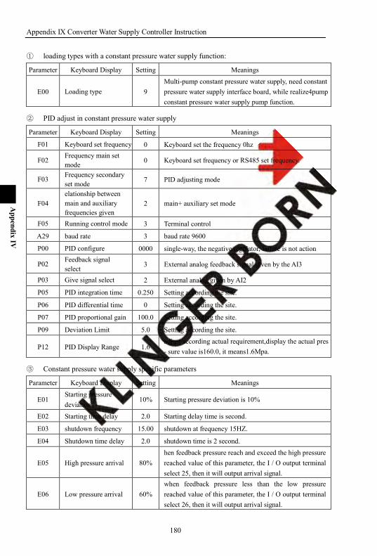
Appendix IX Converter Water Supply Controller Instruction
180
Appendix IV
① loading types with a constant pressure water supply function:
Parameter Keyboard Display Setting Meanings
E00 Loading type 9 Multi-pump constant pressure water supply, need constant pressure water supply interface board, while realize4pump constant pressure water supply pump function.
② PID adjust in constant pressure water supply
Parameter Keyboard Display Setting Meanings
F01 Keyboard set frequency 0 Keyboard set the frequency 0hz
F02 Frequency main set mode 0 Keyboard set frequency or RS485 set frequency.
F03 Frequency secondary set mode 7 PID adjusting mode
F04 elationship between main and auxiliary frequencies given
2 main+ auxiliary set mode
F05 Running control mode 3 Terminal control
A29 baud rate 3 baud rate 9600
P00 PID configure 0000 single-way, the negative regulator, failure is not action
P02 Feedback signal select 3 External analog feedback signal given by the AI3
P03 Give signal select 2 External analog given by AI2
P05 PID integration time 0.250 Setting according the site.
P06 PID differential time 0 Setting according the site.
P07 PID proportional gain 100.0 Setting according the site.
P09 Deviation Limit 5.0 Setting according the site.
P12 PID Display Range 1.6 adjust according actual requirement,display the actual pres - sure value is160.0, it means1.6Mpa.
③ Constant pressure water supply specific parameters
Parameter Keyboard Display Setting Meanings
E01 Starting pressure deviation
10% Starting pressure deviation is 10%
E02 Starting time delay 2.0 Starting delay time is second.
E03 shutdown frequency 15.00 shutdown at frequency 15HZ.
E04 Shutdown time delay 2.0 shutdown time is 2 second.
E05 High pressure arrival 80% hen feedback pressure reach and exceed the high pressure reached value of this parameter, the I / O output terminal select 25, then it will output arrival signal.
E06 Low pressure arrival 60% when feedback pressure less than the low pressure reached value of this parameter, the I / O output terminal select 26, then it will output arrival signal.
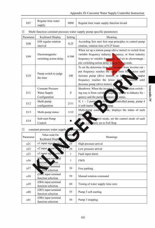
Appendix IX Converter Water Supply Controller Instruction
181
Appendix IV
E07 Regular time water supply
0000 Regular time water supply function invaid
④ Multi-function constant pressure water supply pump specific parameters
Parameter Keyboard Display Setting Meaning
E08 E08 regular rotation interval
0.25 According first start first stop principles to control pump rotation, rotation time of 0.25 hours
E09 Electromagnetic switching action delay
0.500
When set up a station pump (drive motor) to switch from variable frequency industry frequency, or from industry frequency to variable frequency, and set its electromagn - etic switching action delay time is 0.5 seconds.
E10 Pump switch to judge the time
100
To set the determine time 100 seconds from inverter out - put frequency reaches the upper limit frequencies until increase pump (drive motor); or from inverter output frequency reaches the lower limit frequencies until decrease pump (drive motor).
E11 Constant Pressure Water Supply Configuration
0 Shutdown: When the inverter failure,the rotation switch - ing way is from variable frequency pump to industry fre - quency and the pump maintain the status.
E12 Multi-pump configuration
2111 N. 1 ~ 3 pumps are frequency controlled pump, pump 4 is soft-starter controlled pump.
E13 Multi-pump status 1112 Multi-pump control mode, displays the status of each pump
E14 Soft-start Pump Control
Multi-pump control mode, set the control mode of each pump, i currently set to Full Stop
⑤ constant pressure water supply IO parameters:
Parameter Value read On
Keyboard Display Setting Value
Meanings
o21 o1 input signal select 1 25 High pressure arrival
o22 o2 input signal select 2 26 Low pressure arrival
o23 o3 input signal select 3 1 Fault input alarm
o36 (DI1) input terminal function selection 1 FWD
o37 (DI2)input terminal function selection 39 Free parking
o38 (DI3) input terminal function selection
59 Manual rotation command
o39 (DI4) input terminal function selection
60 Timing of water supply time-zero
o40 (DI5) input terminal function selection
55 Pump 3 soft starting
o41 (DI6) input terminal function selection
56 Pump 3 stopping


Product Feedback
Dear users:
Thank you for your interest and purchase the products! In order to provide better service for you, we hope to be able to timely access to your personal information and your purchased products information .we hope to learn about your present and future demand for products and also your valuable feedback on our products. In order to help you get our service faster and more convenient, please visit our company web site refer to column "technologies and services" and "Download" for feedback. 1) download the updated manual for your products.
2) read and download various of product technical information, such as operation instruction, product specification and features, FAQ, etc.
3) application case sharing.
4) technical consult, on-line feedback
5) feedback product information and customer requirement information through e-mail.
6) inquiry for the latest products, obtain various types of additional services such as warranty and extended.