foreword - confinedmasonry.org · period. the formation of lumps in the cement is one of the major...
TRANSCRIPT

1
FOREWORD On 8th October, 2005 the worst earthquake in the history of Pakistan, measuring 7.6 on
the Richter scale, struck Kashmir and the northern areas of Pakistan. According to an
official count, 80000 people lost their lives, thousands were injured and millions were left
homeless.
It is a known fact that it is not earthquake that kills people; it is the destruction of the
buildings which cause human and financial loss. Therefore, if the buildings are
constructed in such a way that they can withstand the earthquake forces, the life and
material loss can be minimized significantly. Keeping in view this fact, in the wake of 8th
October 2005 earthquake, several governmental and non governmental organizations
launched projects that were aimed at the reduction of disastrous effects of the earthquakes
in future. UNDP, a subsidiary of United Nations Organization, also started few such
projects, one of which included the development of an easy and understandable pictorial
manual, following which the residential buildings can be made safer against earthquakes.
On the basis of his vast experience and technical expertise, this project was handed over
to Dr. Qaisar Ali, a distinguished professor of civil engineering department, NWFP,
University of Engineering & Technology, Peshawar.
This manual tries to provide instructions regarding materials and pictorial presentations
for the construction of earthquake resistant construction of buildings. This manual is
focused on construction in those areas of Pakistan which are prone to high intensity
earthquakes e.g., Quetta, Mansehra and Chitral etc. However, these guidelines are also
applicable to earthquake resistant building construction in the rest of Pakistan, with some
amendments, which are given at the end of the manual. Moreover these guidelines are
applicable to one or two storey buildings only.
People are generally of the view that earthquake resistant construction increases the cost
of construction manifold. This is a wrong notion. We can confidently state that by
following the instructions in this manual, earthquake resistant houses can be constructed
in any part of Pakistan with only 5 to 10% addition to the cost.
At the end we expect that this manual will be equally beneficial for laymen, masons,
contractors and site engineers dealing with building construction. INSHALLAH
www.nwfpuet.edu.pk www.eec.edu.pk 0092-91-9218569

2
Seismic Hazard Zones Based on the intensity of earthquakes, a given region or a country can be divided into
different seismic zones. Pakistan is also divided into such four zones. Zone 1 refers to an
area which experiences earthquakes of light intensity. Zone 2 includes the areas where
earthquakes of moderate intensity can be expected. Similarly, severe earthquakes may
occur in the zone categorized as zone 3. Zone 4 is the zone which is struck by
earthquakes of very high intensity.
Seismic zoning of major cities of Pakistan is given in Table 1. In addition; the seismic
zoning map of Pakistan is given in Figure 1, in which seismic zones of all the cities of
Pakistan are shown.
Table 1: Seismic Zones of different cities of Pakistan
City Zone City Zone Islamabad 2B Karachi 2B Lahore 2A Hyderabad 2A Faisalabad 2A Quetta 4 Peshawar 2B Ziarat 4 Abbotabad 3 Gilgitt 3
www.nwfpuet.edu.pk www.eec.edu.pk 0092-91-9218569

3
Figu
re 1
: Se
ism
ic z
onin
g m
ap o
f Pak
ista
n.
www.nwfpuet.edu.pk www.eec.edu.pk 0092-91-9218569

4
Construction materials
Cement: 1. Fresh cement is like powder which is usually available in market in sealed bags.
On opening the bag, cement starts absorbing moisture from the air and with the
passage of time small lumps are formed (Fig.2), as a result of which, strength of
cement is reduced. Therefore, the cement bag once opened should be used as soon
as possible.
Lumps
Fig.2: Lumps in cement
2. The lumps in the cement also appear if their sealed bags are stocked for a long
period. The formation of lumps in the cement is one of the major indications of
old cement. The use of such cement should be avoided.
3. Always use a trusted brand of cement with good quality and avoid the use of
substandard cement.
www.nwfpuet.edu.pk www.eec.edu.pk 0092-91-9218569

5
4. Tests can be carried out to assess the strength of cement. This facility is available
in all the engineering universities of Pakistan and most of the governmental and
non governmental organizations involved in construction activities.
Sand, Khaka and Crush 1. Sand, Khaka and Crush should be clean from soil particles and vegetation. The
presence of such impurities reduces the strength of concrete and mortar.
2. Always prefer the gravel (crush) obtained from crushing machines.(Fig.3)
3. The gravel (crush) should be well graded, containing aggregates of different sizes
in proper proportions. Concrete prepared from gravels having one size is
relatively weaker.
Fig.3: Gravel obtained from crushing machine
4. The size of gravel used for the preparation of concrete should be less than ¾
inches (19mm).
www.nwfpuet.edu.pk www.eec.edu.pk 0092-91-9218569

6
5. Khaka is sand like material obtained from the crushing plants during the crushing
of stones. Khaka, if free from soil particles, when used in the mortar for the
construction of masonry walls, is not harmful.
Water 1. Drinking water should be used for the preparation of mortar and concrete because
the use of contaminated water would result in a significant reduction in the
strength of mortar and concrete.
Bricks 2. Always use A-class bricks in the masonry walls.(Fig.4)
3. All the bricks should be of the same size. (Fig.4)
4. The brick should be properly burnt. The edges and corners of the bricks should
not be deformed or damaged.
Fig.4: First Class Bricks
www.nwfpuet.edu.pk www.eec.edu.pk 0092-91-9218569

7
5. The quality of bricks can be assessed by striking two bricks against each other.
The striking of two A-class bricks against each other would result in a metallic
ringing sound. Moreover, if this kind of brick is dropped from a height of 4 feet
on hard ground, it does not break. (Fig.5, 6)
Fig.5: Striking of two bricks with each other
www.nwfpuet.edu.pk www.eec.edu.pk 0092-91-9218569

8
Fig.6: Dropping of brick from 4 feet height
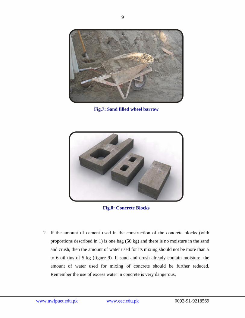
Concrete Blocks: 1. The blocks used in the construction of masonry walls should be constructed of
concrete with a ratio of 1:4:8 which mean the use of one bag of cement, two
wheelbarrows of sand (Picture 7) and four wheelbarrows of crush. If this
proportion of sand and crush is exceeded, the blocks constructed of such concrete
would be very weak. The use of such blocks in the construction of masonry may
prove to be dangerous.
www.nwfpuet.edu.pk www.eec.edu.pk 0092-91-9218569
9
Fig.7: Sand filled wheel barrow
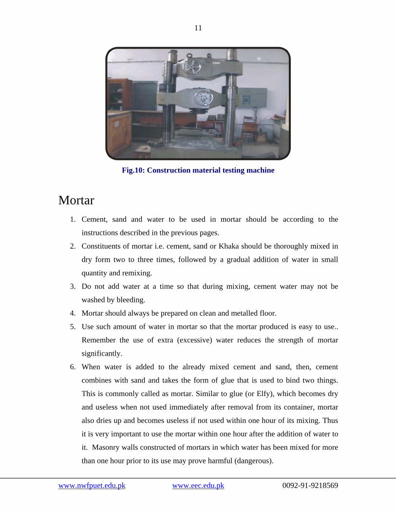
Fig.8: Concrete Blocks
2. If the amount of cement used in the construction of the concrete blocks (with
proportions described in 1) is one bag (50 kg) and there is no moisture in the sand
and crush, then the amount of water used for its mixing should not be more than 5
to 6 oil tins of 5 kg (figure 9). If sand and crush already contain moisture, the
amount of water used for mixing of concrete should be further reduced.
Remember the use of excess water in concrete is very dangerous.
www.nwfpuet.edu.pk www.eec.edu.pk 0092-91-9218569

10
3. The use of blocks that are cracked, warped or having broken edges and corners
should be avoided.
Fig.9: Five Kg oil tin to measure water for mortar and concrete
Steel 1. Steel free from rust and oil should be used.
2. If large quantity of steel is to be used, it should be tested for its properties from a
reputed organization. All the engineering universities in Pakistan as well as most
of the governmental and non governmental organizations involved in construction
activities have the facility of steel testing. (Fig.10)
www.nwfpuet.edu.pk www.eec.edu.pk 0092-91-9218569
11
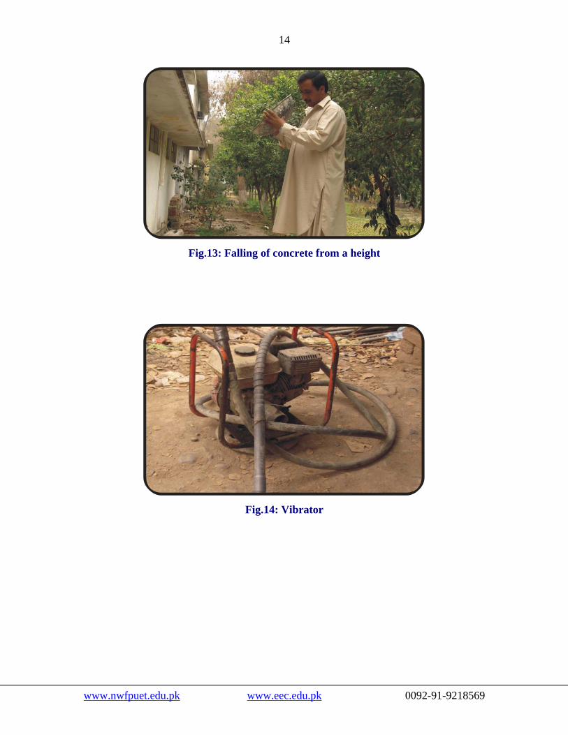
Fig.10: Construction material testing machine
Mortar 1. Cement, sand and water to be used in mortar should be according to the
instructions described in the previous pages.
2. Constituents of mortar i.e. cement, sand or Khaka should be thoroughly mixed in
dry form two to three times, followed by a gradual addition of water in small
quantity and remixing.
3. Do not add water at a time so that during mixing, cement water may not be
washed by bleeding.
4. Mortar should always be prepared on clean and metalled floor.
5. Use such amount of water in mortar so that the mortar produced is easy to use..
Remember the use of extra (excessive) water reduces the strength of mortar
significantly.
6. When water is added to the already mixed cement and sand, then, cement
combines with sand and takes the form of glue that is used to bind two things.
This is commonly called as mortar. Similar to glue (or Elfy), which becomes dry
and useless when not used immediately after removal from its container, mortar
also dries up and becomes useless if not used within one hour of its mixing. Thus
it is very important to use the mortar within one hour after the addition of water to
it. Masonry walls constructed of mortars in which water has been mixed for more
than one hour prior to its use may prove harmful (dangerous).
www.nwfpuet.edu.pk www.eec.edu.pk 0092-91-9218569

12
7. The ratio of mortar for plastering should be 1:4 which means the addition of one
bag of cement to two wheelbarrows of sand (Picture 7). The masonry walls should
be thoroughly soaked with water before the application of plaster.
Concrete 1. Cement, sand, crush and water for use in concrete should be according to
aforementioned instructions.
2. The constituents of concrete should be mixed with the mixer (Fig.11). In case of
non availability of mixer, the dry constituents should be mixed three to four times
with the help of shovels followed by gradual addition of water and subsequent
remixing.
Fig.11: Concrete ingredients/constituents mixing machine
3. A simple way to assess the quantity of water in concrete is to press the wet
concrete in hand. In case of good quality concrete, the cement slurry does not
flow out between the fingers. (Fig.12)
4. When cement, sand and crush are thoroughly mixed together and water is added,
the cement combines with water to form a glue type substance. Just like glue (or
Elfy) that dries and loses its effectiveness when not used shortly after removal
from their container. Similarly concrete, when not used within one hour after its
www.nwfpuet.edu.pk www.eec.edu.pk 0092-91-9218569

13
mixing with water, would become dry and useless. Thus it is very important to
use the concrete within one hour after water is added to it. If more than one hour
passes after the concrete is mixed with water, the beams, columns and slabs
constructed of such a concrete would be weak.
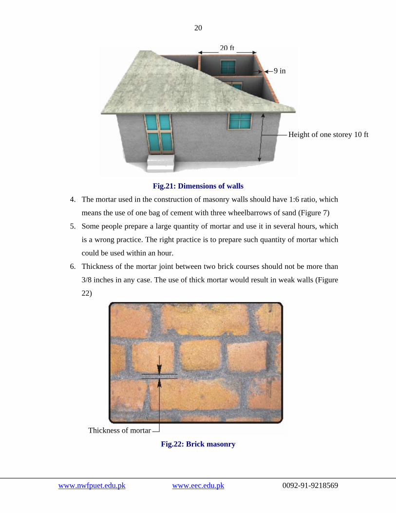
5. If it happens to use concrete by dropping from a height, the height of fall should
not be more than 6ft (Fig.13), because it leads to segregation of concrete which
causes severe reduction in its strength.
6. Concrete should be compacted with the help of a vibrator (Fig.14) after placing
each layer of 1 to 2 feet when pouring beams, slabs or columns. Remember that
strength of vibrator compacted concrete is much more than that of non compacted
concrete. If a vibrator is not available than compaction can be done by tamping it
with a thick steel rod.
7. All the concrete members such as columns, beams and roof slabs should be kept
wet by pouring water for fourteen days.
Fig.12: Pressing of concrete in hand
www.nwfpuet.edu.pk www.eec.edu.pk 0092-91-9218569
14
Fig.13: Falling of concrete from a height
Fig.14: Vibrator
www.nwfpuet.edu.pk www.eec.edu.pk 0092-91-9218569

15
INSTRUCTIONS FOR FIRED CLAY BRICKS
OR SOLID BLOCKS MASONRY BUILDINGS The previous chapter (chapter 2) deals with the instructions about the construction
materials that are used for the construction of residential buildings whereas this chapter
(chapter 3) instructs on the construction of the different components of residential
buildings. These instructions are categorized into two parts: the general instructions and
special instructions. The general instructions include the Site selection, Shape,
Foundations, Wall construction and the size of windows and doors. Whereas in special
instructions, the principles regarding major earthquake resisting elements i.e., beams and
pillars are discussed.
General Instructions Site Selection
1. Avoid construction near an unstable slope, because unstable slopes are prone to
slip during an earthquake.(Fig.15)
Fig.15: House collapsed due to slipped slope during earthquake.
www.nwfpuet.edu.pk www.eec.edu.pk 0092-91-9218569

16
2. Avoid construction near rivers or any other places where the ground water level is
very high. During an earthquake, the buildings constructed in such areas
experience settlement of foundations.
3. Foundation of the whole building should be constructed on the same level. The
foundation constructed on different levels may lead to settlement of the building
(Fig.16)
Fig.16: Building constructed on unleveled foundation leading to its settlement.
Shape 1. The shape of building should be regular. Buildings of irregular shape cannot resist
the earthquake forces efficiently (Fig.17)
www.nwfpuet.edu.pk www.eec.edu.pk 0092-91-9218569

17
Fig.17 (A): Irregular shaped building
Fig.17 (B): Irregular shaped building
Fig.17(C): Regular shaped building
2. The plan of building should be square or rectangular.
3. The length of a building having rectangular plan should not be greater than 4
times its width.(Fig.18)
4. If due to some reason, the length of plan has to be provided greater than 4 times
its width, or the plan is of a complicated shape, then the plan should be sub
divided into squares or rectangles (Fig.18)
www.nwfpuet.edu.pk www.eec.edu.pk 0092-91-9218569

18
Building having complicated drawing Length of building greater than 4 times its width
4L
4L
4L4L
4LL
L
4L
Fig.18: Drawing of building
Foundations 1. The minimum depth and width of foundation should be 3ft (Fig.20) in case of soft
soil. If the soil is hard then the depth of foundation may be limited to 1.5ft.
2. After the excavation and leveling of the earth surface, a 6 inch thick concrete pad
(1:3:6) should be provided (Fig.20).
3. In case of loose soil, 3 bars of half inch diameter should be provided lengthwise
and half inch diameter bars should be provided widthwise at a spacing of 12
inches (Fig.20).
www.nwfpuet.edu.pk www.eec.edu.pk 0092-91-9218569

19
Fig.19: Strip foundation under the walls of the building
t
Wall 1. T
c
th
2. N
3. T
www.nw
3f
6 inch thick (1:3:6) concrete
3, #4 (1/2 inch dia) bars Fig.20: Foundation detai
construction he thickness of brick walls should not be le
onstructed of solid concrete blocks can
ickness.(Fig.21)
one of the room walls should be longer than 20
he height of each storey in the building should be
fpuet.edu.pk www.eec.edu.pk
# 4 (1/2 inch dia) bars at every 1 foot distance
l
ss than 9 inches, while walls
be of 8 inches minimum
feet (Fig.21)
limited to 10 feet (Fig.21)
0092-91-9218569
20
Fig.21: Dimensions
4. The mortar used in the construction of maso
means the use of one bag of cement with th
5. Some people prepare a large quantity of m
is a wrong practice. The right practice is to
could be used within an hour.
6. Thickness of the mortar joint between two
3/8 inches in any case. The use of thick mo
22)
Thickness of mortar
Fig.22: Brick ma
www.nwfpuet.edu.pk www.eec.edu.
20 ft
9 in
Height of one storey 10 ft
of walls
nry walls should have 1:6 ratio, which
ree wheelbarrows of sand (Figure 7)
ortar and use it in several hours, which
prepare such quantity of mortar which
brick courses should not be more than
rtar would result in weak walls (Figure
sonry
pk 0092-91-9218569

21
7. Clay bricks should be kept soaked in water for one to two hours prior to their use.
In this way, bricks do not absorb the moisture from the mortar and a strong bond
between the mortar and brick is ensured. Whereas concrete blocks need only to be
wetted before their use.
8. Minimum 7 days curing is required for masonry work. Use clean, potable water
for curing. Remember improper curing may reduce the strength of walls
drastically.
9. Curing of plaster on the walls should also be carried out for 7 days.
Openings 1. Provide windows and doors in walls as minimum as possible. If large number of
windows and doors are needed, then they should be distributed equally in four
walls of the room. Avoid provision of large number of windows and doors in a
single wall (Fig.23, 24)
www.nwfpuet.edu.pk www.eec.edu.pk 0092-91-9218569

22
Fig.23: Windows and doors provided in a single wall
Fig.24: Windows and doors distributed in all the walls
2. Do not provide openings (windows and doors) near the corners of walls.
3. The minimum distance of any opening from the wall corner should be 2.5 feet and
the distance between any two openings in a single wall should not be less than 3.5
feet (Fig.25)
4. The total width of all the openings, provided in a single wall, should not be more
than 40% of the total length of wall. For example, if the total length of wall is
15 feet, then, the total width of all the openings should be limited to 6 feet.
(Hint: Total width of openings = 0.4 * Total length of wall)
www.nwfpuet.edu.pk www.eec.edu.pk 0092-91-9218569

23
Figure .25 Distances between doors and win
Special instructions According to the instructions discussed here, the maso
strengthened by providing concrete pillars at specified loca
pillars are connected together with the help of concrete beam
the elements of the building are fixed together and the
withstand the earthquake forces efficiently. This type of cons
Confined Masonry. The distinctive feature of confine
construction of walls before the casting of pillars.
Width of door Width of window Width of window
Length of wall
www.nwfpuet.edu.pk www.eec.edu.pk
Width of door
dows
nry construction is
tions. The wall and
s. By doing so, all
building is able to
truction is known as
d masonry is the
0092-91-9218569

24
Concrete pillars 1. It has been observed that during the earthquake, the corners of the buildings
experience major damage (Figure 26), therefore the building corners should be
strengthened.
F
2. According
and junct
providing
www.nwfpuet.ed
ig.26: Damaged corner of building due to earthquake
to the methodology of confined masonry, the corners of the buildings
ions where two or more than two walls meet, are strengthened by
concrete columns (Figure 27)
u.pk www.eec.edu.pk 0092-91-9218569

25
Concrete pillars
Fig.27: Concrete pillars provided at wall corners
3. In addition, the distance between the two pillars in any wall should not be more
than 20 feet.
4. If a Gable wall is also provided in the building and its height is more than 4 feet,
then concrete pillars should be provided in the middle and at sides at every 8 feet
distance in the Gable wall.(Fig.29)
5. The size of each pillar should be at least 9 x 9 inches. In each pillar, 4 longitudinal
bars of ½ inch diameter along with rings of 3/8 inch diameter placed at 6 inches
should be provided (Figure 28)
#3 (3/8 inch dia) rings at every 6 inch distance
4, #4 (1/2 inch dia) bars
Concrete pillar
Fig.28: Detail of pillar’s reinforcement
www.nwfpuet.edu.pk www.eec.edu.pk 0092-91-9218569

26
6. The concrete used in each pillar should be of proportion (1:2:4) which means
using one bag of cement, one wheelbarrow of sand (Figure 7) and two
wheelbarrows of crush.
7. Use minimum amount of water in concrete. For the construction of concrete
pillars, if one bag of cement (50kg) is needed, and there is no moisture in the sand
or crush, then the quantity of water should not be more than 25-30 kg. In terms of
5kg oil tin (Figure 9), the quantity of water should be limited to 5-6 tins with one
bag of cement. If sand, crush or both are already wet; the amount of water used
for mixing the concrete should further be reduced. It should be remembered that
the use of excess water in concrete is very harmful.
8. The concrete used in the construction of the pillars should be compacted with the
help of a vibrator after pouring each one to two feet of concrete. Remember that
the strength of compacted concrete is very high as compared to uncompacted
concrete. If a vibrator is not available, then the concrete may be compacted by
tamping it with a thick steel rod.
9. Each concrete pillar should be properly cured for at least 14 days.
Concrete Beams 1. If all the members of the building (walls, pillars act) are not properly
interconnected, then the building experiences major damage during an
earthquake. According to confined masonry methodology for constructing
earthquake resistant buildings, it is vital to provide concrete beams at specified
locations in the walls. This helps in binding all the members of the building
together, thus enabling it to resist the earthquake forces.
2. In figure 29, three different types of concrete beams are shown. The concrete
beam provided at the floor level is generally known as plinth beam or plinth band.
The concrete beam provided above the doors and windows is called lintel beam or
www.nwfpuet.edu.pk www.eec.edu.pk 0092-91-9218569

27
lintel band, whereas the concrete beam provided at the roof level is called roof
beam or roof band.
Pillar provided in gable wall
Gable band
Lintel band
Plinth band Roof band
Fig.29: Concrete bands in case of gable roof
Roof slab
Fig.30 Concrete bands provided at specified levels
3. In case of a concrete roof slab, it is not necessary to provide a roo
shown in figure 30. In all the other situations, it is necessary to provid
aforementioned beams in the building.
4. When gable walls are provided, it is necessary to provide a gable beam
the roof beam as shown in figure 29.
www.nwfpuet.edu.pk www.eec.edu.pk 0092-9
Lintel band
f
e
a
1
Plinth band
beam, as
all of the
long with
-9218569

28
5. The width of all aforementioned concrete beams should be equal to the thickness
of wall i.e., 9 inches in case of brick walls and 8 inches in case of block masonry
walls.
6. The depths of all the aforementioned concrete beams are shown in figure 31.
While laying the lintel beams, care must be taken that they not only span the
windows and doors, but like plinth beams and roof beams, they also span the
entire length of the wall. In addition, these beams should also be provided in walls
which do not have windows and doors as shown in figure 29 and 30.
7. In all beams described above, 4 steel bars of ½ inch diameter should be provided
lengthwise along with rings of steel, having a diameter of 3/8 inch, placed at a
distance of 6 inch along the length of the beam.
8. If the width of any opening becomes greater than 6 feet, then the depth of lintel
beam should be increased from 6 inches to 9 inches and 2 additional steel bars of
½ inch diameter should be provided in the lower part of the beams. This will
increase the number of bars in the bottom part of the beam from 2 to 4.
9.
9in
9in
6in
Roof band
Lintel band
Plinth band
#3 ring at every 6 inch distance
4, #4 bars
www.nwfpuet.edu.pk www.eec.edu.pk 0092-91-9218569
29
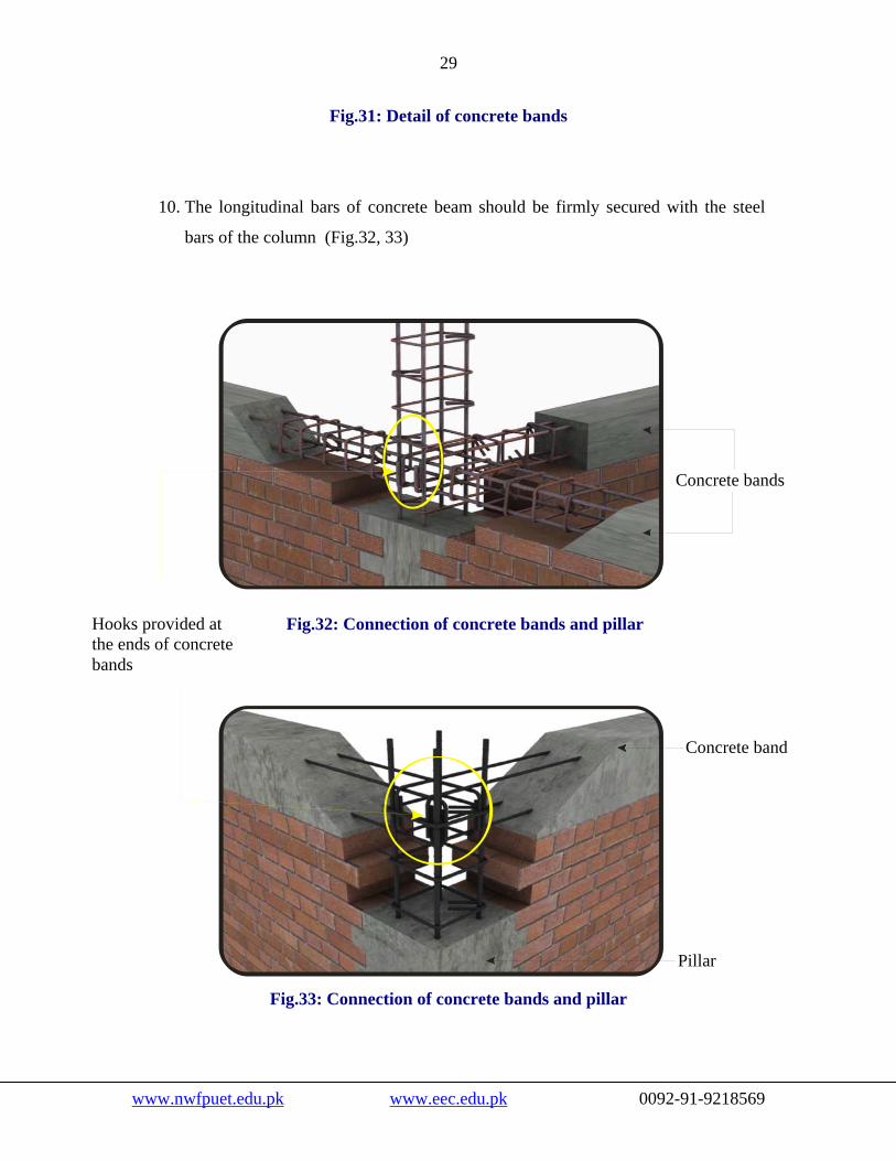
Fig.31: Detail of concrete bands
10. The longitudinal bars of concrete beam should be firmly secured with the steel
bars of the column (Fig.32, 33)
Concrete bands
Fig.32: Connection of concrete bands and pillar Hooks provided at the ends of concrete bands
Concrete band
Pillar
Fig.33: Connection of concrete bands and pillar
www.nwfpuet.edu.pk www.eec.edu.pk 0092-91-9218569

30
11. The concrete used in the concrete bands should be of proportion (1:2:4) which
means using one bag of cement, one wheelbarrow of sand (Figure 7) and two
wheelbarrows of crush.
12. Use minimum amount of water in concrete. For the construction of concrete
beams, if one bag of cement (50kg) is needed, and there is no moisture in the sand
or crush, then the quantity of water should not be more than 25-30 kg. In terms of
5kg oil tin (Fig.9), the quantity of water should be limited to 5-6 tins with one bag
of cement. If sand, crush or both are already wet; the amount of water used for
mixing the concrete should further be reduced. It should be remembered that the
use of excess water in concrete is very harmful.
13. Concrete beams should be properly cured for at least 14 days.
RCC Frame around openings 1. All the openings should be enclosed in 4 inches thick RCC frame.(Figure 34)
4in 4in
Concrete Frame Concrete Frame
Fig.34: RCC Frame provided around the openings
www.nwfpuet.edu.pk www.eec.edu.pk 0092-91-9218569

31
2. In concrete frames, 2 steel bars of ½ inch diameter should be provided
longitudinally along with steel rings having a diameter of 3/8 inch and spaced at 6
inches (Figure 35)
3. The steel bars of the RCC frame should be firmly tied to the steel bars of the lintel
beam (Figure 35)
2, #4 bars
#3 rings at 6 inch distance
Fig.35: Reinforcement detail of RCC Frame
Miscellaneous Instructions 1. Hooks of the steel rings in the pillars and beams should be at an angle of 135o.
(Figure 36)
2. Hooks of the consecutive rings should be at the opposite corners. (Figure 36)
3. Lap in the steel bars should be provided at the mid height of the pillar. (Figure 37)
4. Lap in the steel bars in the beam should be provided at the location as indicated in
Figure 37.
5. It is vital to provide hooks in the steel bars at the ends of beams. (Figures 32, 33)
www.nwfpuet.edu.pk www.eec.edu.pk 0092-91-9218569

32
Hooks on opposite corners of rings
Hook of 135o
2 ft lap Fig.36: Hooks on the opposite sides of rings
Lap in beam Place for lap in pillar
Fig.37: Lap detail of concrete bands and pillars
www.nwfpuet.edu.pk www.eec.edu.pk 0092-91-9218569

33
Some relaxations for buildings of Zone-2: The guidelines for buildings constructed in zone-2 are almost the same as discussed
earlier but some relaxations are allowed at some places, as described below
1. The mortar used in the masonry construction can be of ratio (1:8) which means
the use of one bag of cement with four wheelbarrows of sand.
2. The unsupported length of any wall / distance between any two pillars can be
increased from 20 feet to 25 feet (Fig.21)
3. The minimum distance of any opening from the wall corner can be 2 feet instead
of 2.5 feet (Fig.25)
4. The minimum distance between any two openings, provided in a single wall, can
be 3 feet instead of 3.5 feet (Fig.25)
5. The total width of all the openings, provided in a single wall, can be increased to
50% instead of 40% of the total length of wall. For instance if the wall length is
20 feet, then, the overall width of openings can be limited to 10 feet (Fig.25)
6. It is not necessary to provide RCC frame around the openings in zone-2.(Fig.34)
www.nwfpuet.edu.pk www.eec.edu.pk 0092-91-9218569

34
STEP-WISE CONSTRUCTION OF CONFINED MASONRY
Level the bed of the foundation after excavation.
Pour 1:4:8 concrete at the bottom of the foundation. The thickness of the concrete should be 4 inch and it should have a level surface.
www.nwfpuet.edu.pk www.eec.edu.pk 0092-91-9218569

35
After tying the reinforcement of pillars and foundation, pour 1:3:6 concrete in the foundation having a thickness of 6 inch. Due care must be taken while tying the reinforcement of the pillars to ensure that the lap is provided at the middle of the first storey.
Construct the walls upto the plinth level and provide gaps at the locations of the pillars.
www.nwfpuet.edu.pk www.eec.edu.pk 0092-91-9218569

36
Pour concrete in the pillars upto the plinth level.
After tying the reinforcement of the plinth beams, pour concrete in the plinth beams.
www.nwfpuet.edu.pk www.eec.edu.pk 0092-91-9218569

37
Lap
Construct the wall upto the lintel level while leaving gaps for the pillars. Extend the reinforcement of the pillars further. In case of construction of second storey in future, the length of the pillar reinforcement should be such that to ensure a lap at the middle of the second storey.
Pour concrete upto the lintel level.
www.nwfpuet.edu.pk www.eec.edu.pk 0092-91-9218569

38
After tying the reinforcement of lintel beams, pour the concrete of lintel beams.
Construct the walls upto the roof level and leave gaps for the pillars.
www.nwfpuet.edu.pk www.eec.edu.pk 0092-91-9218569

39
Pour concrete in the pillars upto the roof level.
After tying the reinforcement of the slab, pour the slab concrete.
www.nwfpuet.edu.pk www.eec.edu.pk 0092-91-9218569

40
www.nwfpuet.edu.pk www.eec.edu.pk 0092-91-9218569
Construct the second storey similar to the first storey in a step-wise procedure.