foreword - warszawa yp250a_smsuppl_1999.pdf · particularly important information is distinguished...
TRANSCRIPT


FOREWORDThis Supplementary Service Manual has been prepared to introduce new service and data for the YP250A’99. For complete service information procedures it is necessary to use this Supplementary Service Manualtogether with the following manual.
YP250 SERVICE MANUAL: 4UC-AE1YP250 (J) SUPPLEMENTARY SERVICE MANUAL: 4UC-AE2YP250D SUPPLEMENTARY SERVICE MANUAL: 5DF-AE1
YP250A ’99SUPPLEMENTARYSERVICE MANUAL
1998 by Yamaha Motor Co., Ltd.First Edition, July 1998
Any reproduction or unauthorized usewithout the written permission of
Yamaha Motor Co., Ltd.is expressly prohibited.
NOTE:
WARNING
CAUTION:
EB001000
NOTICEThis manual was produced by the Yamaha Motor Company primarily for use by Yamaha dealers and theirqualified mechanics. It is not possible to include all the knowledge of a mechanic in one manual, so it isassumed that anyone who uses this book to perform maintenance and repairs on Yamaha scooter has abasic understanding of the mechanical ideas and the procedures of scooter repair. Repairs attempted byanyone without this knowledge are likely to render the scooter unsafe and unfit for use.
Yamaha Motor Company, Ltd. is continually striving to improve all its models. Modifications and significantchanges in specifications or procedures will be forwarded to all authorized Yamaha dealers and will appearin future editions of this manual where applicable.
Designs and specifications are subject to change without notice.
IMPORTANT INFORMATIONParticularly important information is distinguished in this manual by the following notations.
The Safety Alert Symbol means ATTENTION! BECOME ALERT! YOUR SAFETYIS INVOLVED!
Failure to follow WARNING instructions could result in severe injury or death to thescooter operator, a bystander or a person inspecting or repairing the scooter.
A CAUTION indicates special precautions that must be taken to avoid damage tothe scooter.
NOTE: A NOTE provides key information to make procedures easier or clearer.
12 4 3
5
6
7
6
8
YP002000
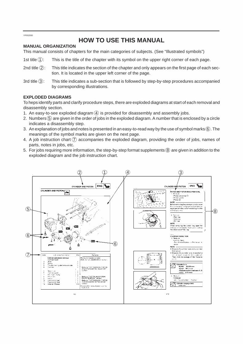
HOW TO USE THIS MANUALMANUAL ORGANIZATIONThis manual consists of chapters for the main categories of subjects. (See “Illustrated symbols”)
1st title 1 : This is the title of the chapter with its symbol on the upper right corner of each page.
2nd title 2 : This title indicates the section of the chapter and only appears on the first page of each sec-tion. It is located in the upper left corner of the page.
3rd title 3 : This title indicates a sub-section that is followed by step-by-step procedures accompaniedby corresponding illustrations.
EXPLODED DIAGRAMSTo heps identify parts and clarify procedure steps, there are exploded diagrams at start of each removal anddisassembly section.1. An easy-to-see exploded diagram 4 is provided for disassembly and assembly jobs.2. Numbers 5 are given in the order of jobs in the exploded diagram. A number that is enclosed by a circle
indicates a disassembly step.3. An explanation of jobs and notes is presented in an easy-to-read way by the use of symbol marks 6 . The
meanings of the symbol marks are given on the next page.4. A job instruction chart 7 accompanies the exploded diagram, providing the order of jobs, names of
parts, notes in jobs, etc.5. For jobs requiring more information, the step-by-step format supplements 8 are given in addition to the
exploded diagram and the job instruction chart.
22
1
3
5
7
9
2
4
8
6
24 25
2321
19 2018
16 1715
1413
11 12
10
GENINFO SPEC
ENG
CARB
ELECCHAS
COOL
INSPADJ
TRBLSHTG
EB003000
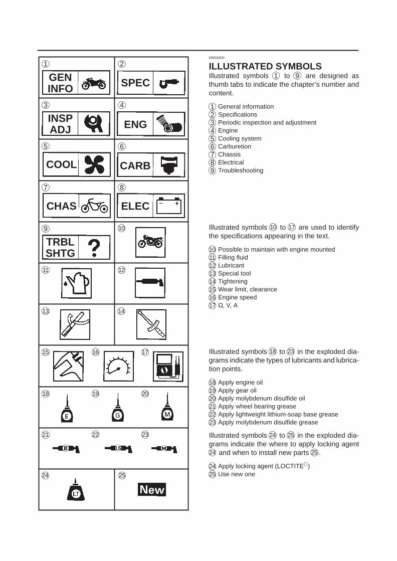
ILLUSTRATED SYMBOLSIllustrated symbols 1 to 9 are designed asthumb tabs to indicate the chapter’s number andcontent.
1 General information2 Specifications3 Periodic inspection and adjustment4 Engine5 Cooling system6 Carburetion7 Chassis8 Electrical9 Troubleshooting
Illustrated symbols 10 to 17 are used to identifythe specifications appearing in the text.
10 Possible to maintain with engine mounted11 Filling fluid12 Lubricant13 Special tool14 Tightening15 Wear limit, clearance16 Engine speed17 Ω, V, A
Illustrated symbols 18 to 23 in the exploded dia-grams indicate the types of lubricants and lubrica-tion points.
18 Apply engine oil19 Apply gear oil20 Apply molybdenum disulfide oil21 Apply wheel bearing grease22 Apply lightweight lithium-soap base grease23 Apply molybdenum disulfide grease
Illustrated symbols 24 to 25 in the exploded dia-grams indicate the where to apply locking agent24 and when to install new parts 25 .
24 Apply locking agent (LOCTITE )25 Use new one
CONTENTS
GENERAL INFORMATION 1. . . . . . . . . . . . . . . . . . . . . . . . . . . . . . . . . . . . . . . . ABS OUTLINE 1. . . . . . . . . . . . . . . . . . . . . . . . . . . . . . . . . . . . . . . . . . . . . . . .
HU OPERATION TEST WHILE ABS IS WORKING 1. . . . . . . . . . . . . YAMAHA ABS PROVIDES 3 MAIN ADVANTAGES 3. . . . . . . . . . . . . SYSTEM LAYOUT 3. . . . . . . . . . . . . . . . . . . . . . . . . . . . . . . . . . . . . . . . . TOTAL SYSTEM BLOCK DIAGRAM 4. . . . . . . . . . . . . . . . . . . . . . . . . . COMPOSITION OF PARTS 4. . . . . . . . . . . . . . . . . . . . . . . . . . . . . . . . . COMPOSITION AND OPERATION OF PARTS 5. . . . . . . . . . . . . . . . SYSTEM OPERATION 10. . . . . . . . . . . . . . . . . . . . . . . . . . . . . . . . . . . . . CAUTION FOR OPERATION 13. . . . . . . . . . . . . . . . . . . . . . . . . . . . . . . .
SPECIAL TOOLS 14. . . . . . . . . . . . . . . . . . . . . . . . . . . . . . . . . . . . . . . . . . . . .
SPECIFICATIONS 15. . . . . . . . . . . . . . . . . . . . . . . . . . . . . . . . . . . . . . . . . . . . . . . . GENERAL SPECIFICATIONS 15. . . . . . . . . . . . . . . . . . . . . . . . . . . . . . . . . . . MAINTENANCE SPECIFICATIONS 17. . . . . . . . . . . . . . . . . . . . . . . . . . . . . .
ENGINE 17. . . . . . . . . . . . . . . . . . . . . . . . . . . . . . . . . . . . . . . . . . . . . . . . . . CHASSIS 17. . . . . . . . . . . . . . . . . . . . . . . . . . . . . . . . . . . . . . . . . . . . . . . . . ELECTRICAL 17. . . . . . . . . . . . . . . . . . . . . . . . . . . . . . . . . . . . . . . . . . . . .
CABLE ROUTING 18. . . . . . . . . . . . . . . . . . . . . . . . . . . . . . . . . . . . . . . . . . . . .
CHASSIS 27. . . . . . . . . . . . . . . . . . . . . . . . . . . . . . . . . . . . . . . . . . . . . . . . . . . . . . . . ANTI-LOOK BRAKE SYSTEM 27. . . . . . . . . . . . . . . . . . . . . . . . . . . . . . . . . .
TERMS EXPLANATION 27. . . . . . . . . . . . . . . . . . . . . . . . . . . . . . . . . . . . BRAKE FORCE AND THE VEHICLE STABILITY 28. . . . . . . . . . . . . . . WHEEL SLIP AND THE HYDRAULIC CONTROL 29. . . . . . . . . . . . . . ABS OPERATION AND THE VEHICLE CONTROL 29. . . . . . . . . . . . . ELECTRONICS ABS FEATURE 30. . . . . . . . . . . . . . . . . . . . . . . . . . . . . ABS COMPONENTS FUNCTION 31. . . . . . . . . . . . . . . . . . . . . . . . . . . . HYDRAULIC UNIT (HU) 34. . . . . . . . . . . . . . . . . . . . . . . . . . . . . . . . . . . . OTHER ABS MECHANISM COMPONENTS 35. . . . . . . . . . . . . . . . . . . ABS TROUBLESHOOTING OUTLINE 37. . . . . . . . . . . . . . . . . . . . . . . . ABS PARTS LOCATION CHART 39. . . . . . . . . . . . . . . . . . . . . . . . . . . . . ABS CONNECTOR LOCATION CHART 40. . . . . . . . . . . . . . . . . . . . . . ABS CIRCUIT DIAGRAM 41. . . . . . . . . . . . . . . . . . . . . . . . . . . . . . . . . . . BASIC INSTRUCTION FOR TROUBLESHOOTING 42. . . . . . . . . . . . BASIC PROCESS FOR TROUBLESHOOTING 43. . . . . . . . . . . . . . . . ABS TROUBLESHOOTING 44. . . . . . . . . . . . . . . . . . . . . . . . . . . . . . . . . [A] MALFUNCTION CHECK BY THE ABS WARNING LIGHT 44. . . . [B] DETAIL CHECK OF MALFUNCTION 44. . . . . . . . . . . . . . . . . . . . . . [B-1] WARNING LIGHT DOES NOT GO ON 44. . . . . . . . . . . . . . . . . . . [B-2] WARNING LIGHT REMAINS GOING ON 44. . . . . . . . . . . . . . . . . [B-3] WARNING LIGHT KEEPS FLASHING 44. . . . . . . . . . . . . . . . . . . [B-4] MALFUNCTION CHECK BY THE ABS SELF DIAGNOSIS(PAST MALFUNCTION) 45. . . . . . . . . . . . . . . . . . . . . . . . . . . . . . . . . . . . [B-5] MALFUNCTION CHECK BY THE ABS SELF DIAGNOSIS(PRESENT MALFUNCTION) 46. . . . . . . . . . . . . . . . . . . . . . . . . . . . . . . . [C] SUPPOSING THE MALFUNCTION CAUSE AND POSITION 47.

[C-1] ONLY ABS WARNING LIGHT DOES NOT GO ON WHENTHE MAIN SWITCH IS TURNED ON 47. . . . . . . . . . . . . . . . . . . . . . . . . [C-2] ABS WARNING LIGHT AND ALL OTHER INDICATORSDO NOT GOES ON 48. . . . . . . . . . . . . . . . . . . . . . . . . . . . . . . . . . . . . . . . [C-3] ABS WARNING LIGHT KEEPS FLASHING 48. . . . . . . . . . . . . . . [C-4] ABS WARNING LIGHT FLASHES EVERY 0.5 SECOND 49. . . [C-5] DIAGNOSIS BY THE MALFUNCTION CODE 50. . . . . . . . . . . . . ECU AND FAIL SAFE RELAY 60. . . . . . . . . . . . . . . . . . . . . . . . . . . . . . . [D-1] MAINTENANCE FOR ECU 61. . . . . . . . . . . . . . . . . . . . . . . . . . . . . [D-2] MAINTENANCE OF THE ABS FAIL-SAFE RELAY 62. . . . . . . . . FRONT WHEEL SENSOR AND SENSOR ROTOR 64. . . . . . . . . . . . . [D-3] MAINTENANCE OF THE FRONT WHEEL SENSOR ANDSENSOR ROTOR 65. . . . . . . . . . . . . . . . . . . . . . . . . . . . . . . . . . . . . . . . . . REAR WHEEL SENSOR AND SENSOR ROTOR 69. . . . . . . . . . . . . . [D-4] MAINTENANCE OF THE REAR WHEEL SENSOR ANDSENSOR ROTOR 70. . . . . . . . . . . . . . . . . . . . . . . . . . . . . . . . . . . . . . . . . . HYDRAULIC UNIT (HU) 72. . . . . . . . . . . . . . . . . . . . . . . . . . . . . . . . . . . . [D-5] MAINTENANCE OF THE HYDRAULIC UNIT (HU) 73. . . . . . . . . AIR BLEEDING 78. . . . . . . . . . . . . . . . . . . . . . . . . . . . . . . . . . . . . . . . . . . . CHECK THE OPERATION OF HYDRAULIC UNITACCORDING TO THE DECOMPRESSION 78. . . . . . . . . . . . . . . . . . . [D-6] FINAL CHECK 78. . . . . . . . . . . . . . . . . . . . . . . . . . . . . . . . . . . . . . . . [D-6-1] CHECKING THE RESERVOIR TANK FLUID LEVEL 79. . . . . [D-6-2] RECHECKING THE ASSEMBLY STATUS OFWHEEL SENSORS 79. . . . . . . . . . . . . . . . . . . . . . . . . . . . . . . . . . . . . . . . [D-6-3] HU OPERATION TEST 2 80. . . . . . . . . . . . . . . . . . . . . . . . . . . . . [D-6-4] DELETING THE MALFUNCTION CODE 82. . . . . . . . . . . . . . . [D-6-5] TRIAL RUN 83. . . . . . . . . . . . . . . . . . . . . . . . . . . . . . . . . . . . . . . . .
REAR SHOCK ABSORBER AND SWING ARM 84. . . . . . . . . . . . . . . . . . .
YP250A ’99 WIRING DIAGRAM
1
ABS OUTLINEGENINFO
NOTE:
GENERAL INFORMATION
ABS OUTLINEIntroductionYP250A is equipped with the ABS (Anti-lock Brake System).
HU OPERATION TEST WHILE ABS IS WORKINGWith the scooter stopped, YP250A allows a driver to test the performance of brake lever reaction forcewhich is generated when the ABS operates.There are two methods for the HU operation test, but this section describes only about the HU operation test 1.HU operation test 1: Equal reaction force to the time of ABS operation is generated on the lever.HU operation test 2: Mainly performs when checking the function after the ABS system has been disas-
sembled, adjusted and serviced. Refer to [D-6-3] HU operation test 2.
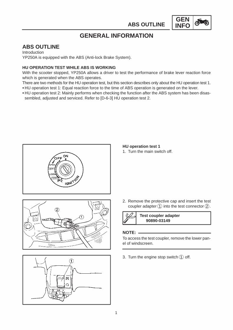
HU operation test 11. Turn the main switch off.
2. Remove the protective cap and insert the testcoupler adapter 1 into the test connector 2 .
Test coupler adapter90890-03149
To access the test coupler, remove the lower pan-el of windscreen.
3. Turn the engine stop switch 1 off.

2
ABS OUTLINEGENINFO
NOTE:
CAUTION:
4. Turn the main switch on.
Wait until the ABS warning light goes off after turn-ing the main switch on.(2 seconds)
5. Turn on the starter switch 1 for longer than 4seconds.
Do not grip the brake lever in this case.
6. After releasing the starter switch (OFF), applythe front brake lever.
Reaction force is generated on the front brakelever 0.5 second later and lasts about 2 se-conds.
7. If the reaction force of front brake lever is lost,apply the rear brake lever while applying thefront brake lever.
Reaction force is generated on the front brakelever 0.5 second later and lasts about 2 se-conds.
8. Turn the main switch off.9. Remove the test coupler adapter from the test
connector.10. Turn the main switch on.11. Set the engine stop switch to RUN position.

3
ABS OUTLINEGENINFO
1 ABS warning light2 Front /Rear master cylinders
Front /Rear brake leversFront /Rear brake switches
3 Fail-safe relay
4 Brake light relay5 Rear brake caliper6 Rear wheel sensor7 Electronic control unit8 Rear disc rotor
9 Hydraulic unit10 Front brake caliper11 Front wheel sensor12 Front disc rotor
YAMAHA ABS PROVIDES 3 MAIN ADVANTAGES1. Securely controls the wheel locking at urgent braking under various conditions of road surface and
weather, and gives full play to tires’ original performance.For higher reliability, the electronic control unit (ECU) is composed of the main and sub processors andequipped with the high level self diagnostic function.
2. Smooth braking can be also performed when the ABS system is activated. Change of chassis behaviorsuch as pitching is few and this system will not damage the rider’s comfortable drive feeling.When the ABS works, the system informs the brake fluid pressure change to a rider via brake levers.
3. Weight of the hydraulic unit (HU) which is the main of system is 2.2 kg for YAMAHA ABS. We designed togather the mass by locating this unit at the central portion of scooter. Since the wheel assembly (wheelsensor) also has extremely lightweight structure, the vehicle’s weight gives no damage to the mobilitywhich YP250A provides such as an excellent safety operation.
SYSTEM LAYOUT

4
ABS OUTLINEGENINFO
1 Rear master cylinder2 Hydraulic unit3 Silencer chamber4 Hydraulic pump5 Electric motor6 Buffer chamber7 Hydraulic control valve
8 Front master cylinder9 Rear brake caliper10 Front brake caliper11 Electronic control unit12 Rear wheel sensor13 Front wheel sensor14 ABS warning light
TOTAL SYSTEM BLOCK DIAGRAM
COMPOSITION OF PARTS
Component Function
Wheel sensor Detects each wheel rotation pulse of front and rear wheelsand inputs them to the electronic control unit.
ABS warning light Warns the ABS system failure to the rider.
Fail-safe relay Supplies the power to the solenoid valve and motor of hy-draulic unit.
Hydraulic unit (HU)Controls the brake fluid pressure of front and rear wheels ac-cording to the output signal sent from the electronic controlunit.
Electronic control unit (ECU)
Outputs the operation signal to the hydraulic unit so that theunit controls matching the road conditions according to thewheel rotation pulses transmitted from front and rear wheelsensors.
In case of ABS system failure, the unit activates the ABSwarning light and shuts off the power to hydraulic unit anddeactivates the ABS operation.

5
ABS OUTLINEGENINFO
CAUTION:
COMPOSITION AND OPERATION OF PARTS1. Wheel sensor and sensor ringA wheel sensor is composed of magnet and coiland installed with front and rear wheels’ housings.The sensor ring attached to front and rear castwheels have 36 serration each. The front end ofwheel sensor is close to the serration.When the sensor rotor with serration rotates, theflux generation from the wheel sensor magnetchanges to generate the alternating voltage in thecoil. The electronic control unit calculates thewheel speed by detecting the repeating times perunit period since this alternating voltage changesthe frequency proportioning to the wheel rotationspeed.
1 At high speed
2 At low speed3 Wheel sensor
4 Sensor rotor
2. ABS warning lightIf the failure occurred in the ABS system, the ABSwarning light alerts the rider by going on the ABSwarning light.When the main switch is turned on, the systemgoes on the light for about 2 seconds to check thedisconnection of ABS warning light and systemfunction, then it goes off.It goes on while the starter switch is pushed tocheck the disconnection.
If the rear wheel is raced by lifting with the cen-terstand or other means, the system mayjudge as the malfunction to flashes or goes onthe ABS warning light.In this case, turn the main switch off once andrestart the engine.The system is normal if the ABS warning lightgoes on and off in about 2 seconds.
1 ABS warning light

6
ABS OUTLINEGENINFO
1 To rear brake master cylinder2 Silencer chamber3 Hydraulic pump4 Electric motor5 Buffer chamber
6 Hydraulic control valve7 To front brake master cylinder8 To the rear brake caliper9 To the electronic control unit10 To the front brake caliper
3. Hydraulic unitHydraulic unit is composed of two pieces of hy-draulic control valve (solenoid valve, flow controlvalve), buffer chamber, pump and silencer cham-ber, and one motor. It adjusts the front/rear wheelbrake fluid pressure to control the wheel rotationcondition according to the signal sent from theelectronic control unit.
7
ABS OUTLINEGENINFO
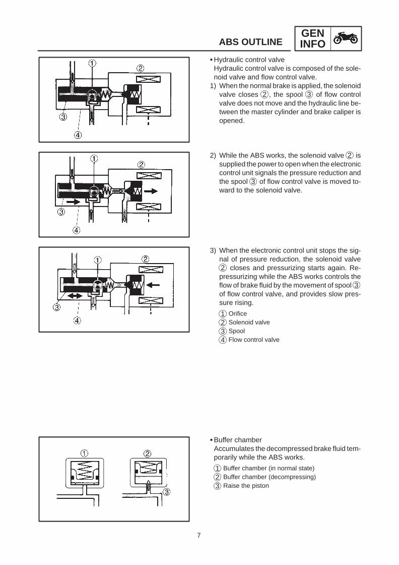
Hydraulic control valveHydraulic control valve is composed of the sole-noid valve and flow control valve.
1) When the normal brake is applied, the solenoidvalve closes 2 , the spool 3 of flow controlvalve does not move and the hydraulic line be-tween the master cylinder and brake caliper isopened.
2) While the ABS works, the solenoid valve 2 issupplied the power to open when the electroniccontrol unit signals the pressure reduction andthe spool 3 of flow control valve is moved to-ward to the solenoid valve.
3) When the electronic control unit stops the sig-nal of pressure reduction, the solenoid valve2 closes and pressurizing starts again. Re-pressurizing while the ABS works controls theflow of brake fluid by the movement of spool 3of flow control valve, and provides slow pres-sure rising.
1 Orifice2 Solenoid valve
3 Spool4 Flow control valve
Buffer chamberAccumulates the decompressed brake fluid tem-porarily while the ABS works.
1 Buffer chamber (in normal state)
2 Buffer chamber (decompressing)
3 Raise the piston
8
ABS OUTLINEGENINFO
Front brakeswitch signal
Power
Rear brakeswitch signal
Stop lampsignal
Starterswitchsignal
Starter switch
Frontwheel sensor
Rearwheel sensor
Voltageregulator
Front brakeswitchcircuit
Rear brakeswitchcircuit
Brakelight circuit
Starterswitchcircuit
Digitalconversioncircuit
Main CPU(Main microcomputer)
Sub CPU(Sub microcomputer)
Memory
Electronic control unit (ECU)
Motor monitorcircuit
Solenoidmotor
Solenoid drivecircuit
Fail-safe relaydrive circuit
Motor relaydrive circuit
Warning lightdrive circuit
Operation modeswitching circuit
Fault codeoutput circuit
Solenoid valve Motor
Hydraulicunit (HU)
Solenoid Motor relay Fail-saferelay
ABS warning light
Checker
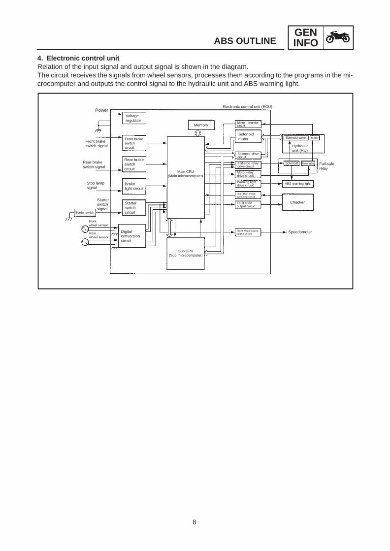
SpeedometerFront wheel speedoutput circuit
4. Electronic control unitRelation of the input signal and output signal is shown in the diagram.The circuit receives the signals from wheel sensors, processes them according to the programs in the mi-crocomputer and outputs the control signal to the hydraulic unit and ABS warning light.

9
ABS OUTLINEGENINFO
Composition and operationFail-safe relay is composed of the solenoid relay and motor relay .Solenoid relay is continued when the electronic control unit outputs the system start signal. Accordingly, thesolenoid valve is activated when the electronic control unit signals the decompression.In case of malfunction, the solenoid relay is turned off and the solenoid valve is deactivated.This makes it impossible to reduce the hydraulic pressure and resumes normal braking. Motor relay is alsocontinued by the signal of electronic control unit and starts the motor simultaneously when the ABS pres-sure reduction begins.When the solenoid is turned off, the motor relay is also turned off, therefore the motor stops its operation incase of malfunction.
1 2
3
11 Power12 Fail-safe relay13 Hydraulic unit
1 Solenoid relay2 Motor relay3 Solenoid valve4 Electric control unit5 Pomp motor relay coil
6 Pump motor monitor7 ABS warning light8 Fail-safe relay coil9 Front solenoid10 Rear solenoid
5. Fail-safe relayFail-safe relay controls the power of hydraulic unitand it is located inside of the tail cover.
1 Fail safe relay

10
1 Brake mastercylinder
2 Brake switch3 Silencer chamber4 Motor5 Pump6 Buffer chamber7 Flow control valve8 Port A9 Spool10 Port B
11 Orifice12 Port D13 Solenoid valve14 Port C15 Brake caliper16 Electronic control
unit17 ABS warning light18 Brake fluid pressure19 Time20 Repressurizing
ABS OUTLINEGENINFO
SYSTEM OPERATIONABS system’s fluid pressure circuit has the 2 lines of front wheel and rear wheel systems. In this section, wedescribe about one system of a front wheel.
Normal brake (ABS not activated)Port D 12 of the solenoid valve is closed since the control signal from the electronic control unit is not sent tothe hydraulic unit. A 8 and B 10 ports of flow control valve spool are opened.Accordingly, when a rider apply the brake lever and the master cylinder hydraulic pressure rises, the brakefluid is directed in the line from Port A 8 to Port B 10 then to brake caliper.At this time, inlet and outlet check valves of pump close the lines and brake fluid is not sent. Therefore, mas-ter cylinder directly pressurizes the brake caliper while braking normally.When the brake lever is released next, the brake fluid in the brake caliper returns then to the master cylindervia Port B 10 , Port A 8 .

11
1 Brake mastercylinder
2 Brake switch3 Silencer chamber4 Motor5 Pump6 Buffer chamber7 Flow control valve8 Port A9 Spool10 Port B
11 Orifice12 Port D13 Solenoid valve14 Port C15 Brake caliper16 Electronic control
unit17 ABS warning light18 Brake fluid pressure19 Time20 Repressurizing
ABS OUTLINEGENINFO
At the time of urgent braking (When ABS works)1) Decompressed state
When the wheel is almost locked, the solenoid valve’s port D 12 opens by the “decompression” signalfrom the electronic control unit. At this time, the spool 9 of flow control valve compresses the returnvalve to close the port B 10 .Brake fluid which has entered through port A 8 is restricted by the orifice 11 .Accordingly, the brake fluid from the brake caliper is sent in the line of Port C 14 , Port D 12 then to thebuffer chamber 6 .The brake caliper fluid pressure is now reduced.Brake fluid which has been stored in the buffer chamber is pumped by the fluid pressure pump inter-locked with motor and returned to the master cylinder.

12
1 Brake mastercylinder
2 Brake switch3 Silencer chamber4 Motor5 Pump6 Buffer chamber7 Flow control valve8 Port A9 Spool10 Port B11 Orifice
12 Port D13 Solenoid valve14 Port C15 Brake caliper16 Electronic control
unit17 ABS warning light18 Brake fluid pressure19 Time20 Repressurizing21 Chamber A22 Chamber B
ABS OUTLINEGENINFO
2) Pressurized statePort D 12 of solenoid valve closes according to the “increase pressure” signal from the electronic controlunit. Also, spool 9 of flow control valve compresses the return spring to close the port B 10 .Brake fluid entered through port A 8 is further restricted by the orifice 11 .Accordingly, the brake fluid in master cylinder is sent in the line of Port A 8 , Port C 14 then to the brakecaliper. However, the brake is pressurized at a constant speed regardless of the brake fluid pressurelevel since the port A’s 8 restriction changes so that the constant pressure difference is maintained be-tween A 21 and B 22 chambers of flow control valve.
13
ABS OUTLINEGENINFO
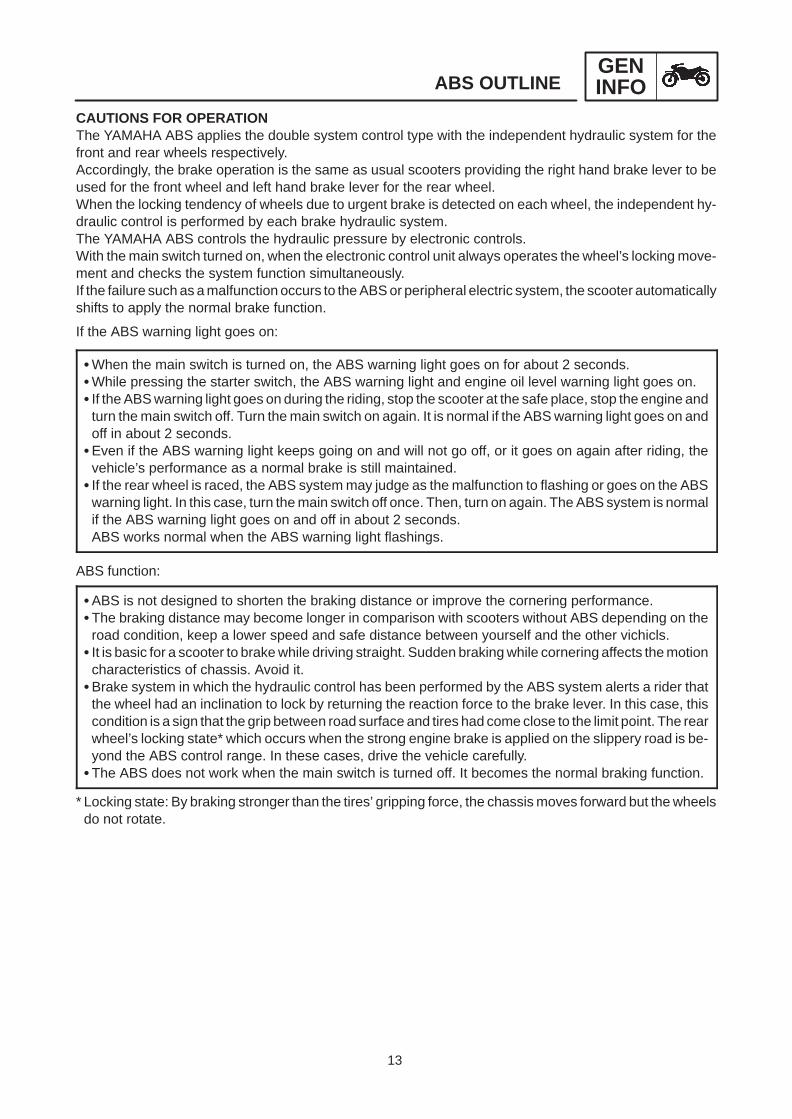
CAUTIONS FOR OPERATIONThe YAMAHA ABS applies the double system control type with the independent hydraulic system for thefront and rear wheels respectively.Accordingly, the brake operation is the same as usual scooters providing the right hand brake lever to beused for the front wheel and left hand brake lever for the rear wheel.When the locking tendency of wheels due to urgent brake is detected on each wheel, the independent hy-draulic control is performed by each brake hydraulic system.The YAMAHA ABS controls the hydraulic pressure by electronic controls.With the main switch turned on, when the electronic control unit always operates the wheel’s locking move-ment and checks the system function simultaneously.If the failure such as a malfunction occurs to the ABS or peripheral electric system, the scooter automaticallyshifts to apply the normal brake function.
If the ABS warning light goes on:
When the main switch is turned on, the ABS warning light goes on for about 2 seconds.While pressing the starter switch, the ABS warning light and engine oil level warning light goes on. If the ABS warning light goes on during the riding, stop the scooter at the safe place, stop the engine and
turn the main switch off. Turn the main switch on again. It is normal if the ABS warning light goes on andoff in about 2 seconds.
Even if the ABS warning light keeps going on and will not go off, or it goes on again after riding, thevehicle’s performance as a normal brake is still maintained.
If the rear wheel is raced, the ABS system may judge as the malfunction to flashing or goes on the ABSwarning light. In this case, turn the main switch off once. Then, turn on again. The ABS system is normalif the ABS warning light goes on and off in about 2 seconds.ABS works normal when the ABS warning light flashings.
ABS function:
ABS is not designed to shorten the braking distance or improve the cornering performance.The braking distance may become longer in comparison with scooters without ABS depending on the
road condition, keep a lower speed and safe distance between yourself and the other vichicls. It is basic for a scooter to brake while driving straight. Sudden braking while cornering affects the motion
characteristics of chassis. Avoid it.Brake system in which the hydraulic control has been performed by the ABS system alerts a rider that
the wheel had an inclination to lock by returning the reaction force to the brake lever. In this case, thiscondition is a sign that the grip between road surface and tires had come close to the limit point. The rearwheel’s locking state* which occurs when the strong engine brake is applied on the slippery road is be-yond the ABS control range. In these cases, drive the vehicle carefully.
The ABS does not work when the main switch is turned off. It becomes the normal braking function.
* Locking state: By braking stronger than the tires’ gripping force, the chassis moves forward but the wheelsdo not rotate.

14
SPECIAL TOOLSGENINFO
EB104000
SPECIAL TOOLSThe following special tools are necessary for complete and accurate tune-up and assembly.Use only the appropriate special tools as this will help prevent damage caused by the use of inappropri-ate tools or improvised techniques.When placing an order, refer to the list provided below to avoid any mistakes.
Tool No. Tool name/Function Illustration
90890-03149
Test coupler adaptor
This tool is used to check the ABS diagnosis.

15
GENERAL SPECIFICATIONS SPEC
SPECIFICATIONSGENERAL SPECIFICATIONS
Model YP250A
Model code: 5DF3 (except for CH)5DF4 (for CH)
Dimensions:Overall lengthOverall widthOverall heightSeat heightWheelbaseMinimum ground clearanceMinimum turning radius
2,110 mm,780 mm
1,330 mm,700 mm
1,500 mm,115 mm
2,600 mm
Basic weight:With oil and full fuel tank 169 kg
Transmission:Primary reduction systemPrimary reduction ratioSecondary reduction systemSecondary reduction ratioTransmission typeOperationSingle speed automatic
Helical gear40/15 (2.667)Sper gear38/15 (2.533)Single speed automatic (V-belt type)Centrifugal automatic type2.34 0.82 : 1
Tire pressure (cold tire):Maximum load-except motorcycleLoading condition A*
frontrear
Loading condition B*frontrear
High-speed ridingfrontrear
186 kg0 90 kg175 kPa (1.75 kg/cm2, 1.75 bar)200 kPa (2.0 kg/cm2, 2.0 bar)90 186 kg200 kPa (2.0 kg/cm2, 2.0 bar)225 kPa (2.25 kg/cm2, 2.25 bar)
200 kPa (2.0 kg/cm2, 2.25 bar)250 kPa (2.5 kg/cm2, 2.5 bar)
Brake:Brake control deviceFront brake type
operationRear brake type
operation
ABSSingle disc brakeRight hand operationSingle disc brakeLeft hand operation
* Load is the total weight of cargo, rider, passenger, and accessories.
16
GENERAL SPECIFICATIONS SPEC
Model YP250A
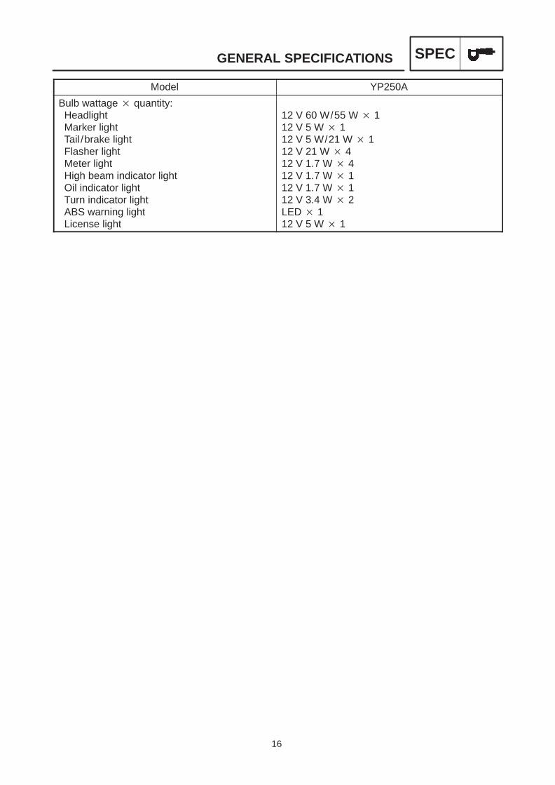
Bulb wattage quantity:HeadlightMarker lightTail /brake lightFlasher lightMeter lightHigh beam indicator lightOil indicator lightTurn indicator lightABS warning lightLicense light
12 V 60 W/55 W 112 V 5 W 112 V 5 W/21 W 112 V 21 W 412 V 1.7 W 412 V 1.7 W 112 V 1.7 W 112 V 3.4 W 2LED 112 V 5 W 1
17
MAINTENANCE SPECIFICATIONS SPEC
MAINTENANCE SPECIFICATIONSENGINE
Item Standard Limit
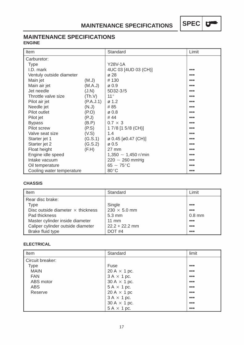
Carburetor:TypeI.D. markVentuly outside diameterMain jet (M.J)Main air jet (M.A.J)Jet needle (J.N)Throttle valve size (Th.V)Pilot air jet (P.A.J.1)Needle jet (N.J)Pilot outlet (P.O)Pilot jet (P.J)Bypass (B.P)Pilot screw (P.S)Valve seat size (V.S)Starter jet 1 (G.S.1)Starter jet 2 (G.S.2)Float height (F.H)Engine idle speedIntake vacuumOil temperatureCooling water temperature
Y28V-1A4UC 03 [4UD 03 (CH)]ø 28# 130ø 0.95D32-3/511ø 1.2# 85ø 0.8# 440.7 31 7/8 [1 5/8 (CH)]1.4ø 0.45 [ø0.47 (CH)]ø 0.527 mm1,350 1,450 r/min220 260 mmHg65 75C80C
CHASSIS
Item Standard Limit
Rear disc brake:TypeDisc outside diameter thicknessPad thicknessMaster cylinder inside diameterCaliper cylinder outside diameterBrake fluid type
Single230 5.0 mm5.3 mm11 mm22.2 + 22.2 mmDOT #4
0.8 mm
ELECTRICAL
Item Standard limit
Circuit breaker:TypeMAINFANABS motorABSReserve
Fuse20 A 1 pc.3 A 1 pc.30 A 1 pc.5 A 1 pc.20 A 1 pc3 A 1 pc.30 A 1 pc.5 A 1 pc.

18
CABLE ROUTING SPEC
1 Front wheel sensor lead2 Wireharness (ABS)3 Rear wheel sensor lead4 Carburetor drain hose5 Carburetor coolant drain hose6 Carburetor air ventilation hose7 Fail safe relay8 Brake light relay9 Electronic control unit (ECU)
10 Rear wheel sensor11 Crankcase12 Over flow hose (fuel filler)13 Hydraulic unit14 Down tube15 Wireharness16 Steering head pipe17 Throttle cable18 Crankcase breather hose
A Route the rear brake hose throughthe guide on the handlebar holder.
B Fasten the wireharness to the staywith a plastic band.Refer to fig D.
C Fasten the throttle cables andwireharness to the down tube witha plastic band.Refer to fig A.
CABLE ROUTING

19
CABLE ROUTING SPEC
D Align the mark on the brake hoseswith clamp, and clamp them.
E Fasten the throttle cable to theframe with a plastic band.Refer to fig B.
F Route the fuel tank over flow hosethrough the clamp on inside of theframe.
G Lower throttle cable is pull side.H Upper throttle cable is push side.I Fasten the wireharness with a
steel clamp on the frame.
J Route the rear wheel sensor asillustration.
K Route the rear wheel sensor leadthrough the guide.
L Route the carburetor air ventila-tion hose, carburetor coolant drainhose and carburetor drain hosethrough the guide.
M Route the carburetor drain hosethrough the guide.
N Route the over flow hose (fuel fill-er) and hydraulic unit drain hosethrough the guide.
O Position the connector of plasticband as illustration.
P Position the connector of the plas-tic band inside of the line.
Q Route the rear wheel sensor leadthrough the front of the crankcasebreather hose.
R Align the white tape on the wire-harness with the steel clamp onthe frame, and fasten them.

20
CABLE ROUTING SPEC
1 Box light2 Rectifier / regulator3 Fuel sender4 Ignition coil5 Roll over valve6 Seat lock cable7 Handlebar switch lead (right)8 Front brake switch lead9 Front brake hose10 Reservoir tank hose
11 Starter switch12 Battery13 Flasher relay14 Coolant reservoir tank15 Crankcase breather hose16 Air filter case17 Front brake hose (IN)18 Front brake hose (OUT)19 Rear brake hose (IN)20 Hydraulic unit coupler
21 Rear brake hose (OUT)22 Igniter23 Down tube24 Wireharness25 Rear brake hose26 Battery leads27 AC magneto lead28 Starter motor lead29 Engine ground lead

21
A Route the box light lead throughfrom the outside of the frame to theinside of the pipe.
B Connect the taillight lead and wire-harness on the mudguard.
C Fasten the fuel sender lead to thepipe with a plastic clamp.
D Fasten the fuel sender lead andauto choke lead with a steel clampon inside of the frame.
CABLE ROUTING SPEC
E Fasten the seat box light switchlead to the hinge with a plasticlocking tie. Route the plastic lock-ing tie into the hole and under theprojection of hinge.
F Route the box switch lead underthe projection of fuel tank hinge.
G Route the box switch lead fromoutside of the fuel tank over flowhose to inside of the pipe.
H Fasten the electronic control unitleads (3 lines) with a plastic band.
I Route the seat lock cable throughthe pipe, and align the mark of seatlock cable with the pipe end.
J Fasten the wireharness and seatlock cable with a steel band on theframe.
K Position the junction of the thermoswitch lead inside of the scooter.
L Align the location tape with thesteel clamp on the frame, and fas-ten them.
22
CABLE ROUTING SPEC
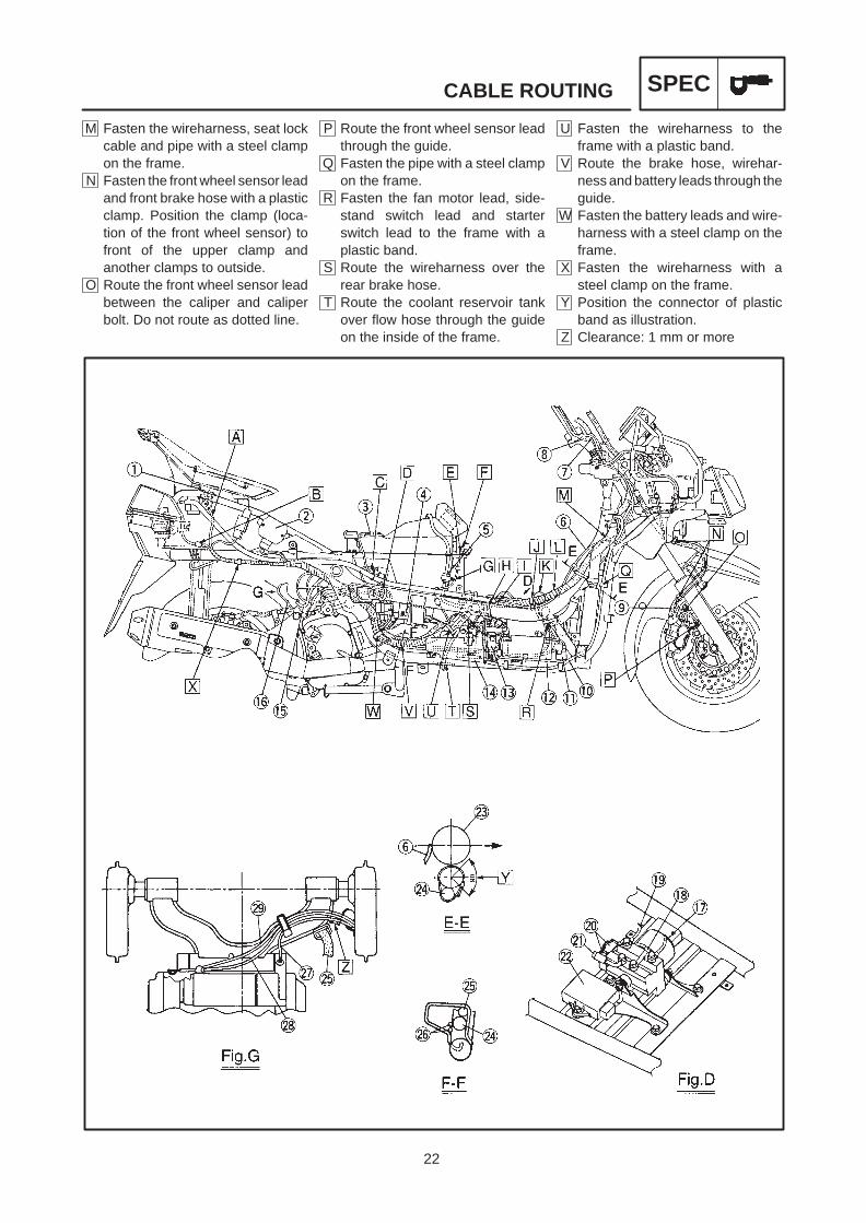
M Fasten the wireharness, seat lockcable and pipe with a steel clampon the frame.
N Fasten the front wheel sensor leadand front brake hose with a plasticclamp. Position the clamp (loca-tion of the front wheel sensor) tofront of the upper clamp andanother clamps to outside.
O Route the front wheel sensor leadbetween the caliper and caliperbolt. Do not route as dotted line.
P Route the front wheel sensor leadthrough the guide.
Q Fasten the pipe with a steel clampon the frame.
R Fasten the fan motor lead, side-stand switch lead and starterswitch lead to the frame with aplastic band.
S Route the wireharness over therear brake hose.
T Route the coolant reservoir tankover flow hose through the guideon the inside of the frame.
U Fasten the wireharness to theframe with a plastic band.
V Route the brake hose, wirehar-ness and battery leads through theguide.
W Fasten the battery leads and wire-harness with a steel clamp on theframe.
X Fasten the wireharness with asteel clamp on the frame.
Y Position the connector of plasticband as illustration.
Z Clearance: 1 mm or more

23
CABLE ROUTING SPEC
1 Seat lock2 Air filter case3 Engine ground lead4 Crankcase breather hose5 Fuel hose6 Vacuum hose7 Sidestand switch lead8 Fan motor lead9 Fuel tank over flow hose10 Reservoir tank breather hose11 Starting circuit cutoff relay12 Auto choke lead
13 AC magneto lead14 Starter motor lead15 Seat lock cable16 Fuel pump17 Fuel tank18 Hydraulic unit
A Route the hydraulic unit drainhose under the coolant hose.
B Fasten the fuel tank over flow hosewith a steel clamp on the frame.
C Fasten the sidestand switch leadwith a steel clamp on the frame.
D Route the thermo switch lead out-side of the frame.
E Fasten the wireharness to theframe with a plastic band.
F Route the battery positive lead asillustration.
G Fasten the thermo switch lead andfan motor lead with a steel clampon the frame.

24
CABLE ROUTING SPEC
H Fasten the sidestand switch leadand battery positive lead with asteel clamp on the frame.
I Fasten the sidestand switch leadwith a plastic clamp.
J Route the battery negative leadthrough the front and lower side ofthe flasher relay.
K Fasten the wireharness, AC mag-neto lead, starter motor lead andengine ground lead with a steelclamp on inside of the frame.
L Fasten the AC magneto lead,starter motor lead and engineground lead with a steel clamp onthe engine bracket.
M Route the crankcase breatherhose into the hole of air filter case.
N Route the fuel hose over the vacu-um hose.
O Position the end of the clip to out-side.
P Fasten the front wheel sensor andelectronic control unit lead to theframe with a plastic band.
Q Install the fuse box to the stay onthe frame.
R Fasten the front wheel sensor,fuse lead and electronic controlunit lead to the frame with a plasticband.
S Do not fasten the fuel tank overflow hose with a plastic band.

25
CABLE ROUTING SPEC
1 Front turn signal light (right)2 Front turn signal light (left)3 Handlebar switch lead (right)4 Front stop switch lead5 Seat lock cable6 Throttle cable7 Handlebar switch lead (left)8 Rear brake switch lead9 Handlebar under cover10 Stay11 Horn12 Front brake hose
13 Front wheel sensor14 Horn15 ABS test terminal16 Handlebar upper cover17 Handlebar18 Front turn signal light19 Grip heater lead (option)
A Route the front wheel sensorthrough the guide on the frame.
B Route the handlebar switch leadand front brake switch leadthrough the guide.
C Route the front brake hosethrough the right hole of the han-dlebar under cover.
D Route the rear brake hose throughthe left hole of the handlebar undercover.
E Fasten the handlebar switch lead(left) and rear brake switch lead tothe handlebar with a plastic lock-ing tie. Cut the end of locking tie at5 mm or less.

26
CABLE ROUTING SPEC
F Route the handlebar switch (left)lead and rear brake switch leadthrough the left side of thespeedometer cable.
G Route the front wheel sensorthrough the guide.
H Fasten the front brake hose with abrake hose holder.
I Fasten the headlight lead, hornlead and front wheel sensor leadwith a steel clamp on the stay.
J Route the handlebar switch (left)lead through the front side of thehandlebar under cover.

27
ANTI-LOCK BRAKE SYSTEM (ABS) CHAS
CHASSISANTI-LOCK BRAKE SYSTEMThe YAMAHA ABS is the electronic control sys-tem applying the 2 system control type with the in-dependent hydraulic system for the front and rearwheels respectively.Accordingly, the brake operation is the same asusual scooters providing the right hand brake le-ver to be used for the front wheel and left handbrake lever for the rear wheel.When the locking movement of wheels due to ur-gent braking is detected on each wheel, the inde-pendent hydraulic control is performed by eachbrake hydraulic system.
TERMS EXPLANATIONWheel speed
Rotation speed of front and rear wheels itself isthe wheel speed.
Chassis speedWhen the brake is applied, the wheel rotation islowered and the chassis speed reduces. Howev-er, the chassis tends to travel forward by its iner-tia even though the wheel rotation is lowered.The speed of chassis itself is the chassis speed.
Brake forceThis is the force to reduce the speed by braking.
Wheel lockOn a slippery road, if the brake was applied toostrong the vehicle tends to run on, but the wheelsstop rotating. This state is called a wheel lock.
Side forceThis is the force to act on tires which supports thevehicle sideways.

28
ANTI-LOCK BRAKE SYSTEM (ABS) CHAS
A
B
Brake force
Side force
Slip ratio(%)
Fric
tion
forc
e be
twee
n th
etir
e an
d ro
ad s
urfa
ceF
rictio
n fo
rce
betw
een
the
tire
and
road
sur
face
Less slipperyroad surface
Controlling zone
Slippery road surface
Slip ratio(%)
Slip ratioWhen the brake is applied, slipping occurs be-tween tires and road surface, then the differenceis made between the wheel speed and chassisspeed. This is called a slip.Slip ratio is the value to show the rate of slippingand defined by the following formula.
Slip ratio =Chassis speed – Wheel speed
Chassis speed 100 (%)
0%: There is no slip between wheels and roadsurface providing the complete rotationof wheels.
100%: The wheel speed is “0”, i.e. the state ofwheel locking.
BRAKE FORCE AND THE VEHICLE STABILITYWhen the brake pressure is increased, it brakesthe wheel and the slip occurs between the tire androad surface to generate the brake force. The limitof this brake force is determined by the frictionforce between the tire and road surface and has aclose relation with the state of slipping. Slippingstate is shown by the slip ratio.Therefore, the side force has also a close relationwith the slipping state . Figure A shows the rela-tion of them. If the vehicle is braked while keepingthe proper slip ratio, it is possible to gain the maxi-mum brake force without losing the much sideforce.The ABS has a function which allows these tirecharacteristics to bring their ability into full play onthe slippery or less-slippery road. (Figure B )

29
ANTI-LOCK BRAKE SYSTEM (ABS) CHAS
Vehicle speed
Wheel speed
Pressurizing
Decompressing
Brake force
NOTE:
WHEEL SLIP AND THE HYDRAULIC CON-TROLThe ABS computer calculates each wheel speedaccording to the rotation signal receiving from thefront and rear wheel sensors. In addition, the com-puter calculates the vehicle travel speed and rateof speed reduction with wheels based on thewheel speed values.Differences between the travel speed and wheelspeed of wheels calculated as above are equal tothe wheel slip. When the wheel tends to lock, thewheel suddenly reduces its speed. When the slipof wheel and speed reduction rate of wheel ex-ceeds the preset value, the ABS computer judgesthat the wheel is in the tendency to lock. If the slipis large and the wheel tends to lock (A point in thefigure), the ABS computer decompresses thebrake fluid of caliper and increases the pressurewhen the locking tendency disappears (B point inthe figure).If slip is large and the wheel tends to lock (A pointin the figure), the ABS computer executes thepressure reduction and increases the pressurewhen the locking tendency disappears (B point inthe figure).
ABS OPERATION AND THE VEHICLE CON-TROLWhen the ABS is activated, it means that thewheel has a tendency to lock and the vehicle con-trol is close to its limit. To recognize this vehiclecondition, the brake lever is designed to generatethe reaction force.
Reaction force to the brake lever while the ABSworks is normal.

30
ANTI-LOCK BRAKE SYSTEM (ABS) CHAS
Brake force
Side force
Slip ratio(%)
Fric
tion
forc
e be
twee
n th
etir
e an
d ro
ad s
urfa
ce
WARNING
WARNING
Side force also reduces when the vehicleequipped with the ABS is braked as same as ve-hicles with ordinary brake system. Accordingly,sudden braking while cornering loses the ve-hicle’s stability regardless of ABS existence. It isnot the ABS function to prevent the vehicle fromslipping to sideways.
It is basic for a scooter to brake while drivingstraight. Even the ABS equipped scooter can-not stop slipping sideways by losing its stabil-ity due to sudden brake while cornering.
The function of ABS works to control the brake’shydraulic pressure and prevent the wheel’s lock-ing tendency.Accordingly, locking of wheels which may occurwhen the engine brake is applied on the slipperyroad is beyond the ABS control range.
Even the ABS equipped scooter cannot pre-vent the locking tendency of wheels on the ex-tremely slippery road caused by the enginebrake.
ELECTRONICS ABS FEATUREThe YAMAHA ABS is the anti-lock brake systemdeveloped under the most advanced electronicstechnology.The control is processed with good response pro-viding various travel conditions for scooters.The system also equipments the highly developedself diagnostic function and designed to return tothe normal braking state by detecting the problemcondition correctly even if the vehicle is struck bytroubles.At the moment, the ABS warning light of meterpanel alerts a drive by goes on.The YAMAHA ABS is designed to restore thetrouble history in the memory allowing easy trou-bleshooting by reading the malfunction code.
31
ANTI-LOCK BRAKE SYSTEM (ABS) CHAS
CAUTION:
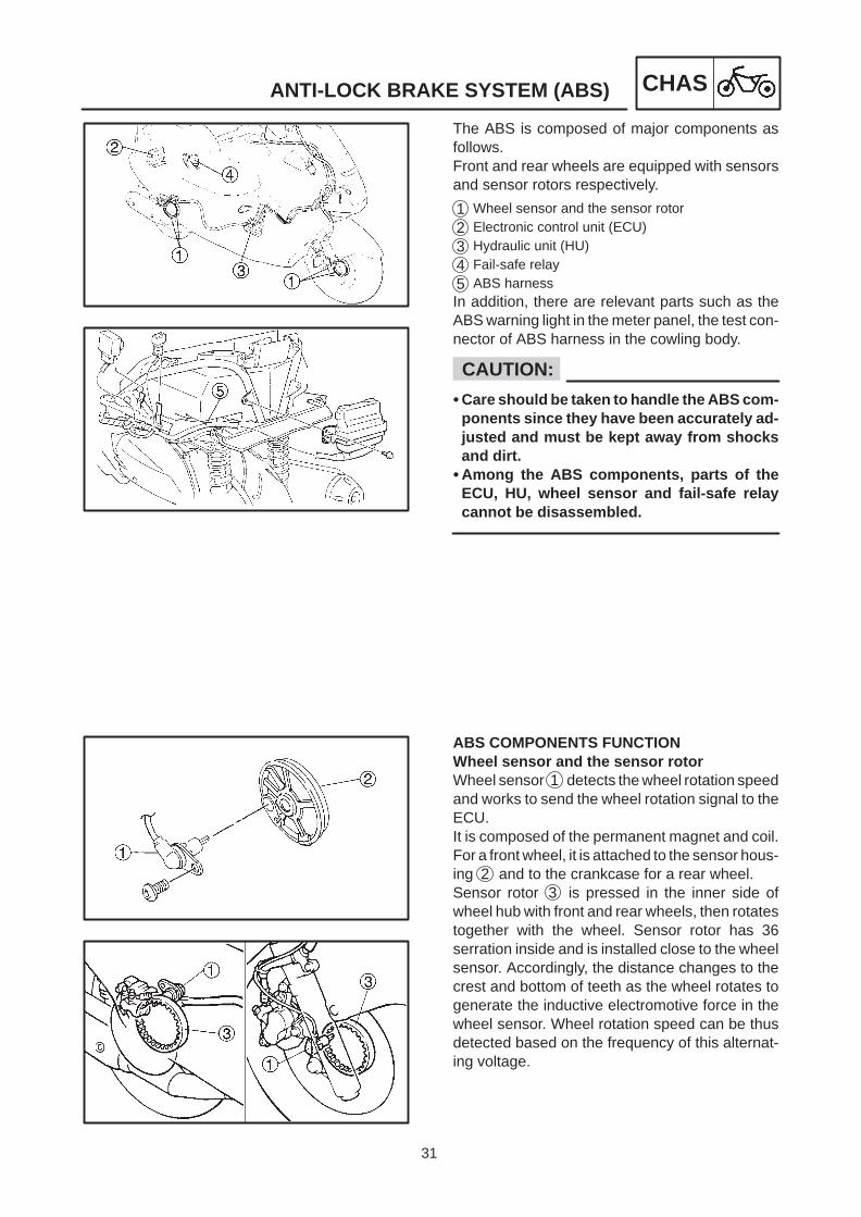
The ABS is composed of major components asfollows.Front and rear wheels are equipped with sensorsand sensor rotors respectively.
1 Wheel sensor and the sensor rotor2 Electronic control unit (ECU)
3 Hydraulic unit (HU)
4 Fail-safe relay5 ABS harnessIn addition, there are relevant parts such as theABS warning light in the meter panel, the test con-nector of ABS harness in the cowling body.
Care should be taken to handle the ABS com-ponents since they have been accurately ad-justed and must be kept away from shocksand dirt.
Among the ABS components, parts of theECU, HU, wheel sensor and fail-safe relaycannot be disassembled.
ABS COMPONENTS FUNCTIONWheel sensor and the sensor rotorWheel sensor 1 detects the wheel rotation speedand works to send the wheel rotation signal to theECU.It is composed of the permanent magnet and coil.For a front wheel, it is attached to the sensor hous-ing 2 and to the crankcase for a rear wheel.Sensor rotor 3 is pressed in the inner side ofwheel hub with front and rear wheels, then rotatestogether with the wheel. Sensor rotor has 36serration inside and is installed close to the wheelsensor. Accordingly, the distance changes to thecrest and bottom of teeth as the wheel rotates togenerate the inductive electromotive force in thewheel sensor. Wheel rotation speed can be thusdetected based on the frequency of this alternat-ing voltage.

32
Front brakeswitch signal
Power
Rear brakeswitch signal
Stop lampsignal
Starterswitchsignal
Starter switch
Frontwheel sensor
Rearwheel sensor
Voltageregulator
Front brakeswitchcircuit
Rear brakeswitchcircuit
Brakelight circuit
Starterswitchcircuit
Digitalconversioncircuit
Main CPU(Main microcomputer)
Sub CPU(Sub microcomputer)
Memory
Electronic control unit (ECU)
Motor monitorcircuit
Solenoidmotor
Solenoid drivecircuit
Fail-safe relaydrive circuit
Motor relaydrive circuit
Warning lightdrive circuit
Operation modeswitching circuit
Fault codeoutput circuit
Solenoid valve Motor
Hydraulicunit (HU)
Solenoid Motor relay Fail-saferelay
ABS warning light
Checker
SpeedometerFront wheel speedoutput circuit
ANTI-LOCK BRAKE SYSTEM (ABS) CHAS
Electronic control unit (ECU)Electronic control unit 1 controls the ABS and isinstalled inside the taillight unit. To protect fromwater invasion, it is enveloped by a cover 2 .
As shown in the block diagram below, the ECUtakes in the wheel sensor signals from front andrear wheels and also receives the signals fromvarious monitor circuits. Two of main and sub mi-crocomputers are installed in the ECU providingmutual monitoring.

33
ANTI-LOCK BRAKE SYSTEM (ABS) CHAS
Soft wear operation flow
Turn the main switch on
Initialize
Self diagnosis(at static)
Self diagnosis(at riding)
Receive the signals
Control operation
Judge of decompressing /pressurizing
8 /1000seconds
NOTE:
The operation result is confirmed by the monitorcircuit. Based on the result, the control signals ofhydraulic unit (HU) and fail-safe relay will be is-sued.
ABS control operationThe ABS control operation performed in ECU is di-vided into 2 parts as follows.
1 Hydraulic control
2 Self diagnosisThese operations will be performed repeating onetime in every 8/1000 seconds. In the case of fail-ure occurrence, it is stored in the malfunction codememory allowing easy find and check of failures.
Depending on the type of failure, it will not be re-corded in the memory. (e.g. battery voltage drop)
Hydraulic unit (HU)This hydraulic unit (HU) 1 is the component tocontrol the hydraulic pressure of brake system un-der the signal of ECU, and located beside the bat-tery box at the center of scooter central part.

34
1 Rear mastercylinder
2 Hydraulic unit3 Silencer chamber4 Hydraulic pump5 Electric motor6 Buffer chamber7 Hydraulic control
valve8 Front master
cylinder9 Rear brake
caliper10 Front brake caliper11 Electronic control unit
12 Rear wheel sensor13 Front wheel sensor14 ABS warning light
ANTI-LOCK BRAKE SYSTEM (ABS) CHAS
HYDRAULIC UNIT (HU)Hydraulic unit is composed of two pieces of hydraulic control valve (solenoid valve, flow control valve), buff-er chamber, pump and silencer chamber, and one motor. It adjusts the front/rear wheel brake fluid pressureto control the wheel rotation condition according to the signal transmitted from the electronic control unit.
HU componentsComponents of each system are five parts as fol-lows.
1 Flow control valve
2 Solenoid valve3 Buffer chamber
4 Hydraulic pump5 Silencer chamberFlow control valve 1 works to keep the brake fluidflow at a constant flow rate while the ABS works.This valve also increases and decreases thebrake fluid pressure together with the solenoidvalve 2 .Buffer chamber 3 accumulates the decom-pressed brake fluid temporarily while the ABSworks.Hydraulic pump 4 is driven by the motor and it re-turns the brake fluid which has been stored in thebuffer chamber 3 to the master cylinder side line.In addition, to increase the quietness, the silencerchamber 5 is equipped.
6 Brake master cylinder
7 Brake caliper
8 ABS warning light9 ECU

35
ANTI-LOCK BRAKE SYSTEM (ABS) CHAS
Main switchOFF
Main switchON
“ABS”warning light Goes off
Goes on for2 seconds. Goes off
Preparation
Main switchOFF
Main switchON
Main switchOFF
Main switchON
Starter switchON
Starter switchOFF
“ABS”warninglight
Goes on for2 seconds.
Goesoff
Goesoff
Goes on while thestarter switch is pushed.
Goesoff
Preparation
“ABS”warning light Goes on
NOTE:
NOTE:
OTHER ABS MECHANISM COMPONENTSABS warning lightThe ABS warning light 1 is designed to inform theABS self diagnostic result and located in the meterpanel.
Going on the ABS warning light1. Turn the main switch on
It goes on for about 2 seconds. It executes theself diagnosis during this period and goes off.
2. When the main is turned on and starter switchis pushed.
Depends on the following requirementWhen applying the brake leverWhen the engine stop switch is offWhen the sidestand is used
ABS warning light keeps going on while starterswitch is pashed. The ABS warning light discon-nection is confirmed.
Engine oil warning light goes on while the starterswitch is pushed.
3. Light goes on while riding.Malfunction is detected in the ABS. In this case,the ABS hydraulic control is not performed andit becomes the normal braking state.

36
ANTI-LOCK BRAKE SYSTEM (ABS) CHAS
ABSwarning light
Goes on
Goes off
Preparation
NOTE:
NOTE:
4. Flashes while riding.No problem exists with the ABS function, but itis estimated that the input has unstable factors.(For details, refer to the troubleshooting sec-tion.)
The test coupler adapter may be connected withthe test connector.
5. Test connectorBy removing the lower panel of windscreen,the installed 4 pin connector 1 can be seen.This is the test connector to call the ABS mal-function code.
When the test coupler adapter 1 is connectedwith the test connector, the malfunction historyrecorded in the ECU will be displayed by theABS warning light flashing.
Test coupler adapter90890-03149
If the scooter rides with the test coupler adapterconnected, the ABS warning light flashes.

37
ANTI-LOCK BRAKE SYSTEM (ABS) CHAS
WARNING
ABS TROUBLESHOOTING OUTLINEThis section describes the troubleshooting about ABS in details. Read carefully this service manual beforerepairing various malfunctions, understand and perform the service.Electronic control unit (ECU) has the self diagnostic function. When failures occur in the system, the ABSwarning light of meter panel alerts the malfunction.Trouble shooting mentioned below describes the cause pursuing and service method according to the in-dication by ABS warning light. For troubleshooting other than these items, perform by following the normalservice method.
When the maintenance or check has been performed on related parts to ABS, be sure to execute the“final check” before delivering the scooter to the customer. Refer to [D-6] FINAL CHECK.
1. ABS warning light goes on and the ABS condition1) When the ABS warning light keeps going on It works as a normal brake.Detecting the malfunction by means of the ABS self diagnostic function.
2) Light goes on and off at the time of starting ABS operation is normal.ABS warning light goes on for 2 seconds every time the main switch is turned on and goes off afterward.ABS warning lights go on while the starter switch is pushed.
3) When the ABS warning light flashes ABS operation is normal.Brake switch is defective or improperly adjusted.Rear wheel is racing.Continuous riding on extremely uneven roads.
2. Self diagnosis and servicesECU has the self diagnostic function. By utilizing this function, quick and secure services are possible.Previously occurred error phenomenon can be checked since it also installs the memory for storing mal-function history.
“In case malfunctions are detected”It is disabled to call the malfunction code by using the ABS warning light since the ABS warning light alreadygoes on. Connect the test coupler adapter to the test connector, connect a pocket tester to the terminal oflight green lead and check by its pointing needle movement. (Refer to [B-5])
“In case any malfunctions are not detected” It is possible to call the malfunction code by using the ABS warn-ing light. You can check it by using a pocket tester. Note everything if more than two items of malfunctioncodes are recorded.

38
ANTI-LOCK BRAKE SYSTEM (ABS) CHAS
“Deleting the malfunction code”When the malfunction service is finished, check the normal operation of scooter then delete the malfunctioncode (Refer to [D-6]). By deleting the malfunction code memory, it is possible to pursue the cause correctly ifthe next defective phenomenon occurred.
Self diagnosis by ECUECU performs the static check for whole system when the main switch is turned on. It is also possible tocheck the malfunction while riding. It is possible to check the recorded malfunction data by using a testeror utilizing the ABS warning light of meter by setting the ECU to the self diagnostic mode since all mal-functions which has been once detected are recorded.
3. Differences between the normal handling and services on a vehicleCare should be taken not to damage components by shocks and pulling too much since the ABS compo-
nents are precisely adjusted.ECU, HU, Wheel sensors and relay boxes are united assemblies.Malfunction history in ECU is recorded. Delete it when the service is finished. (This is because the past
malfunction contents will be redundantly displayed when the same malfunction occurred again.)

39
ANTI-LOCK BRAKE SYSTEM (ABS) CHAS
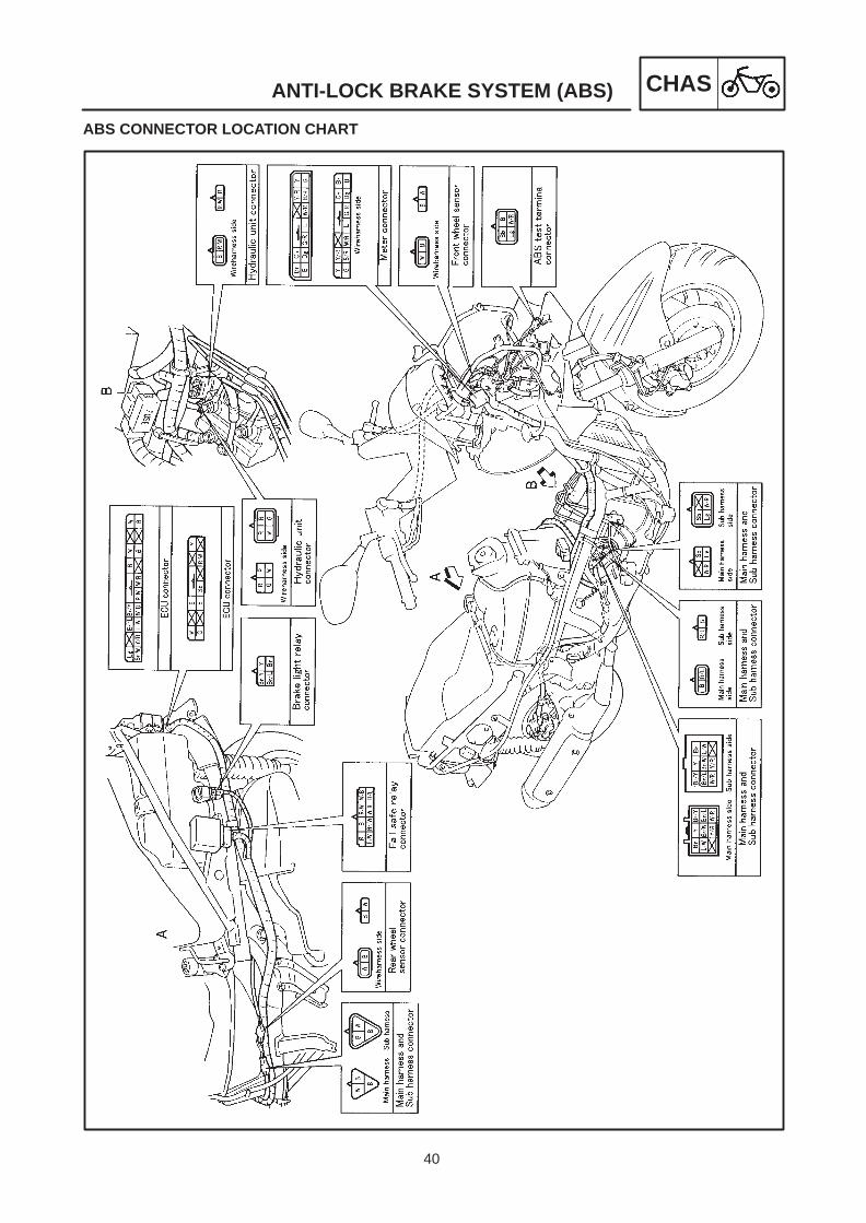
1 Electronic control unit (ECU)2 Brake light relay3 Fail-safe relay4 Front brake hose (Front brake
master cylinder-Hydraulic unit)5 Rear brake hose (Rear brake
master cylinder-Hydraulic unit)
6 ABS warning light7 Test connector8 Front sensor rotor9 Front wheel sensor10 Front brake hose (Hydraulic unit-
front brake caliper)
11 Hydraulic unit (HU)12 Fuse box13 Rear brake hose (Hydraulic unit-
rear brake caliper)14 Rear wheel sensor15 Rear sensor rotor
ABS PARTS LOCATION CHART
40
ANTI-LOCK BRAKE SYSTEM (ABS) CHAS
ABS CONNECTOR LOCATION CHART

41
3 Main switch4 Battery5 Fuse (main)8 Fuse (ABS motor)16 ECU (electronic control unit)17 Front wheel sensor
18 Rear wheel sensor19 Fail safe relay20 Hydraulic unit27 Front brake switch28 Brake light relay29 Rear brake switch
46 ABS warning light48 Speedometer60 Start switch62 Fuse (ABS)
ANTI-LOCK BRAKE SYSTEM (ABS) CHAS
ABS CIRCUIT DIAGRAM

42
ANTI-LOCK BRAKE SYSTEM (ABS) CHAS
WARNING
WARNING
BASIC INSTRUCTION FOR TROUBLESHOOTING
Execute the troubleshooting on each malfunction from [A] to [D] in sequence.Use the sufficiently charged regular batteries only.
[A]Malfunction check by the ABS warning light
[B]Detail check of malfunctionResults by self diagnosis are displayed by the ABS warning light or tester according to the ECU’s opera-tion.
[C]Supposing the malfunction cause and positionFind the malfunction cause by reasoning the place and situation where it occurred.
[D]ABS system servicesExecute the final check after disassembly and assembly.
Perform the troubleshooting [A] [B][C][D] in order. Be sure to follow the order since it resultsin the wrong diagnosis if the order is differently taken or omitted.
43
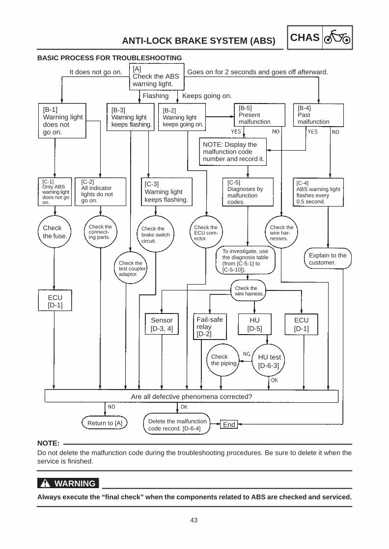
It does not go on. [A]Check the ABSwarning light.
Goes on for 2 seconds and goes off afterward.
Flashing
[B-1]Warning lightdoes notgo on.
[B-3]Warning lightkeeps flashing.
Keeps going on.
[B-2]Warning lightkeeps going on.
[B-5]Presentmalfunction
[B-4]Pastmalfunction
NOTE: Display themalfunction codenumber and record it.
[C-1]Only ABSwarning lightdoes not goon.
[C-2]All indicatorlights do notgo on.
[C-3]Warning lightkeeps flashing.
[C-5]Diagnoses bymalfunctioncodes.
[C-4]ABS warning lightflashes every0.5 second.
Checkthe fuse.
Check theconnect-ing parts.
Check thebrake switchcircuit.
Check theECU com-ector.
Check thewire har-nesses.
Check thetest coupleradaptor.
ECU[D-1]
To investigate, usethe diagnosis table(from [C-5-1] to[C-5-10]).
Explain to thecustomer.
Check thewire harness.
Sensor[D-3, 4]
Fail-saferelay[D-2]
Checkthe piping.
HU test [D-6-3]
HU[D-5]
ECU[D-1]
Are all defective phenomena corrected?
Return to [A] Delete the malfunctioncode record. [D-6-4]
End
ANTI-LOCK BRAKE SYSTEM (ABS) CHAS
NOTE:
WARNING
BASIC PROCESS FOR TROUBLESHOOTING
Do not delete the malfunction code during the troubleshooting procedures. Be sure to delete it when theservice is finished.
Always execute the “final check” when the components related to ABS are checked and serviced.

44
ANTI-LOCK BRAKE SYSTEM (ABS) CHAS
NOTE:
(sky-blue) T/C
(light green) T/F
Grounding (black)
Warning light (white/red)
NOTE:
ABS TROUBLESHOOTING[A] MALFUNCTION CHECK BY THE ABS WARNING LIGHTTurn the main switch on. (Do not start the engine.)1) Warning light does not go on. [B-1]2) Warning light keeps going on. [B-2]3) Warning light keeps flashing. [B-3]4) Warning light goes on for two seconds and goes off. [B-4]
[B] DETAIL CHECK OF MALFUNCTION[B-1] WARNING LIGHT DOES NOT GO ONDo other indicators operate normally?1) They work normally. [C-1]2) They do not work normally. [C-2][B-2] WARNING LIGHT REMAINS GOING ONCheck the ECU in the taillight unit. Is the coupler securely connected?1) It is connected. [B-5]2) It is disconnected. Securely connect until the “click” sound is heard.[B-3] WARNING LIGHT KEEPS FLASHING
Check the battery terminal voltage before proceeding to [B-3].
Check the test connector located in the cowling body. Is the T/C terminal connected to the ground?
1) It is grounded. Disconnect the grounding lead from the T/C terminal and put on the protective cap.
When the test coupler adapter is connected, the T/C terminal is designed to grounded.
2) It is not grounded. [C-3]

45
ANTI-LOCK BRAKE SYSTEM (ABS) CHAS
(sky-blue) T/C
(light green) T/F
Grounding (black)
ABS warning light (white/red)
Test coupler adapter
As an example, this pattern shows the malfunction code 14.
ABS warninglight go on.
ABS warninglight goes off.
Time (sec.)
Arrangement and the function of test couplersECU becomes the malfunction diagnostic mode when the T/C terminal is grounded.Malfunction code which the ECU generated in the malfunction diagnostic mode (rise and fall of voltage)
is output at the T/F terminal.ABS warning light terminal is used when checking the ABS warning light circuit.To ground the T/C terminal, connect the test coupler adapter with the test connector. Before connecting,
check if the battery is sufficiently charged.
[B-4] MALFUNCTION CHECK BY THE ABS SELF DIAGNOSIS (PAST MALFUNCTION)Remove the screen and check the location of test connector 1 . Remove the protective cap and connect thetest coupler adapter 2 with the test connector. T/C terminal (sky-blue) is now grounded.
1) ABS warning light flashes every 0.5 second. (longer than 6 seconds) [C-4]2) ABS warning light keeps flashing in the pattern as shown below. [C-5]

46
B
A CTest connector
Lock plate
Protective cap
Grounding
T/C terminalT/F terminal Light terminal
(white/red)
(black)
(white/red)
(light green)Test coupleradapter
(light green)
(white/red)
This example is the pattern whichshows malfunction code 12.
This example is the pattern whichshows malfunction code 21.
Time(second)
8 V
0 V
ANTI-LOCK BRAKE SYSTEM (ABS) CHAS
NOTE:
[B-5] MALFUNCTION CHECK BY THE ABS SELF DIAGNOSIS (PRESENT MALFUNCTION)
Before proceeding to [B-5], read the part of [B-3] “Arrangement and the function of test coupler”.
Remove the screen and check the location of test connector. Connect the test coupler adapter with the testconnector in order to ground the T/C terminal (sky-blue). (Figure - A )
Set the range of pocket tester to DC20V. Connect the negative (-) terminal of tester to the T/F terminal (lightgreen) and positive (+) terminal to the positive (+) terminal of battery. (Figure - B )Read the tester indication. (Figure - C )
As an example, ”10 digits/1 digit pattern” of tester reading is shown below.

47
ANTI-LOCK BRAKE SYSTEM (ABS) CHAS
NOTE:
[C] SUPPOSING THE MALFUNCTION CAUSE AND POSITION[C-1] ONLY ABS WARNING LIGHT DOES NOT GO ON WHEN THE MAIN SWITCH IS TURNED ON
Check following the numbers in sequence.
1. Visual check1) Check the fuse 1 . (ABS)
Check the cause of fuse blown, repair and replace with a new one.2) Check the ABS harness and wire harness connector.
Check whether the ABS connector is securely connected with the wire harness. Both harnesses are con-nected by two connectors. Check both connectors. (Refer to ABS CONNECTOR LOCATION CHART)
3) Check the connection of ECU and ABS harness.Check whether the ABS harness is securely connected with the ECU. (Refer to ABS CONNECTORLOCATION CHART)
2. Confirmation by the test coupler adapter1) Connect the test coupler and test coupler adapter. (Refer to [B-5])2) Connect the warning light terminal (white/red) of test coupler adapter to the ground (or the negative (-)
terminal of battery). If the ABS warning light goes on, the inside of ABS harness may be disconnected. If the ABS warning light does not goes on, the ABS warning light lead may be disconnected or the warn-
ing light’s contact may be defective.3) Remove the ECU connector (Refer to ABS CONNECTOR LOCATION CHART) and check the continuity
of white/red lead. (ECU and test coupler adapter sides of white/read wire) If there is a continuity, the ECU is defective. Replace the ECU. (Refer to [D-1] MAINTENANCE OF
ECU) If there is no continuity, the warning light circuit in the ABS harness is defective. Disconnection and oth-
ers Correct (Refer to CIRCUIT DIAGRAM)
48
ANTI-LOCK BRAKE SYSTEM (ABS) CHAS
NOTE:
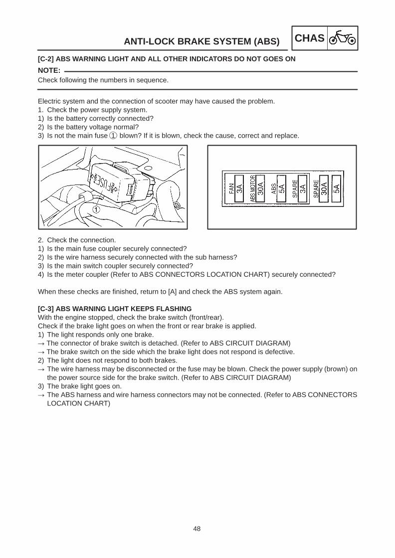
[C-2] ABS WARNING LIGHT AND ALL OTHER INDICATORS DO NOT GOES ON
Check following the numbers in sequence.
Electric system and the connection of scooter may have caused the problem.1. Check the power supply system.1) Is the battery correctly connected?2) Is the battery voltage normal?3) Is not the main fuse 1 blown? If it is blown, check the cause, correct and replace.
2. Check the connection.1) Is the main fuse coupler securely connected?2) Is the wire harness securely connected with the sub harness?3) Is the main switch coupler securely connected?4) Is the meter coupler (Refer to ABS CONNECTORS LOCATION CHART) securely connected?
When these checks are finished, return to [A] and check the ABS system again.
[C-3] ABS WARNING LIGHT KEEPS FLASHINGWith the engine stopped, check the brake switch (front/rear).Check if the brake light goes on when the front or rear brake is applied.1) The light responds only one brake. The connector of brake switch is detached. (Refer to ABS CIRCUIT DIAGRAM) The brake switch on the side which the brake light does not respond is defective.2) The light does not respond to both brakes. The wire harness may be disconnected or the fuse may be blown. Check the power supply (brown) on
the power source side for the brake switch. (Refer to ABS CIRCUIT DIAGRAM)3) The brake light goes on. The ABS harness and wire harness connectors may not be connected. (Refer to ABS CONNECTORS
LOCATION CHART)
49
ANTI-LOCK BRAKE SYSTEM (ABS) CHAS
[C-4] ABS WARNING LIGHT FLASHES EVERY 0.5 SECOND.
This state means that the ECU has not recorded the past malfunction. If the ABS warning light goes on oncein a while but does not record the past malfunction, it is estimated that the ABS warning light went on orflashed because of failures on other places of scooter. Explain the possible reason enough to the customerfor better understanding.
1. Warning light flashesFollowing are probable causes for cases when the ABS warning light flashed while riding, but it recov-ered to be “normal”, or “the ABS warning light flashed but it stopped flashing when the main switch wasturned off once and turned on again”.
1) While the scooter stood with the centerstand, the rear wheel was rotated. The system is normal.2) The rear wheel raced. The system is normal.3) Ran in wheelie. The system is normal.4) The scooter continuously ridded on the extremely uneven road. The system is normal.5) The brake switch is defective or improperly adjusted. Replace or adjust.
2. Voltage dropFor the ABS to operate correctly, the voltage should be always higher than the specified voltage. If thevoltage drops lower than 10V, the ABS warning light goes on and stops the ABS operation. When thevoltage recovers to be higher than 10V, the system restarts to operate, but the state which the voltagedropped lower than 10V means that there are failures with magneto, battery or rectifier/regulator. Cor-rect the failures following regular procedures for normal operation of power supply system.
3. ABS is stopped by ECUThis state occurs because the ECU judged that the system must stop since it was exposed to the envi-ronment of extremely strong radio wave, static electricity or radioactivity.
No defectiveness is shown at present. There is no problem about system function. Explain the customerthat the ABS system will operate normally.

50
ANTI-LOCK BRAKE SYSTEM (ABS) CHAS
NOTE:
[C-5] DIAGNOSIS BY THE MALFUNCTION CODEMalfunction codes explained in [B-4] and [B-5] are used to judge what type of problems have occurred. Theyare judged by using the table as follows.
Records all indicated malfunction codes and check the contents for confirmation.
Malfunc-tion code
Problem Check point Reference
11
*1
Front wheel sensor signal does notcome in correctly.
Installation of the front wheel sensor Front wheel sensor lead, connectorABS harness circuit Front sensor housing
[C-5-1] andthe electricitygroup
12
Rear wheel sensor signal does notcome in correctly.
Installation of the rear wheel sensorRear wheel sensor lead, connectorABS harness circuitRear sensor housing
[C-5-2] andthe electricitygroup
13/14Error signal is detected by the front “13”or rear “14” wheel sensor.
Installation of sensorsSensor housingsSensor rotors
[C-5-3]
15/16No continuity in sensor circuits Continuity of sensors
ABS harness circuitConnection of sensor connectors
[C-5-4]
21Solenoid circuit is disconnected orshort-circuited.
ABS harness circuitConnector of solenoidSolenoid
[C-5-5] andthe electricitygroup
31Disconnection is detected on thesystem of fail-safe relay and solenoid.
ABS harness circuit Fail-safe relay circuitConnector of solenoid
[C-5-6]
32Defective operation of the fail-saferelay is detected.
Fail-safe relayABS harness circuit
[C-5-7] andthe electricitygroup
33
Defective operation of the motor isdetected.(Motor stops and will not rotate.)
ABS harness circuitConnector of motor Fail-safe relayHU motor circuit
[C-5-8] andthe electricitygroup
34Defective operation of the motor isdetected.(Motor keeps running and will not stop.)
Fail-safe relayABS harness circuitHU motor circuit
[C-5-9] andthe electricitygroup

51
ANTI-LOCK BRAKE SYSTEM (ABS) CHAS
NOTE:
Malfunctioncode
Problem Check point Reference
41
Front wheel will not recover from thelocking tendency even though thesignal is continuously sent from theECU to release the hydraulic state.(while the battery voltage is normal)
Brake draggingHU operation test
(Refer to [D-6-3])Front wheel brake line
[C-5-10]
42
Rear wheel will not recover from thelocking tendency even though thesignal is continuously sent from theECU to release the hydraulic state.(while the battery voltage is normal)
Brake draggingHU operation test
(Refer to [D-6-3])Rear wheel brake line
[C-5-11]
51
Front wheel will not recover from thelocking tendency even though thesignal is continuously sent from theECU to release the hydraulic state.(while the battery voltage is low)
Brake draggingHU operation test
(Refer to [D-6-3])Front wheel brake lineBattery voltage
[C-5-12]
52
Rear wheel will not recover from thelocking tendency even though thesignal is continuously sent from theECU to release the hydraulic state.(while the battery voltage is low)
Brake draggingHU operation test
(Refer to [D-6-3])Rear wheel brake lineBattery voltage
[C-5-13]
Malfunctionedat present
Inside of ECU may malfunction. ABS harness circuit(test coupler circuits)
[D-1] andthe electric-at resent
[B-5](Tester always
(test cou ler circuits)ECU (Replace)
the electric-ity group
(Tester alwaysindicates 8V.)
*1 Malfunction code “11” is indicated if the rear wheel rotates for longer than about 20 seconds with the frontwheel stopped, or the rear wheel rotates within one second after the main switch is turned on. (In thecase the scooter stands by the centerstand.)
Malfunction code “15” (front wheel sensor), “16” (rear wheel sensor) is indicated when the scooter does notride, and the defective connection of either front or rear sensor is detected.

52
ANTI-LOCK BRAKE SYSTEM (ABS) CHAS
[C-5-1] Malfunction code “11” (Front wheel sensor signal does not come in correctly.)Turn the main switch off once, then turn on again after removing the test coupler adapter.1) ABS warning light remains going on. Defective connection in the front wheel sensor circuit.Sensor connector is detached. [D-3]Sensors or leads are disconnected. [D-3]ABS harness sensor circuit is disconnected. (Refer to ABS CIRCUIT DIAGRAM)ECU connector terminal is disconnected. [D-1]
2) ABS warning light goes on for 2.0 seconds and goes off.1 With the front wheel stopped, the rear wheel was rotated for longer than about 20 seconds. This is not a
malfunction.2 Signal is not generated from the front wheel sensor.Sensor is not in place. [D-3]Sensor rotor is defective. [D-3]3 Front wheel sensor circuit is short-circuited.Sensor or leads are short-circuited. [D-3]Sensor circuit of ABS harness is short-circuited. (Refer to ABS CIRCUIT DIAGRAM)4 Front wheel sensor output dropsSensor signal output may drop due to failures on bearings, wheel axle, wheel and sensor housing of front
wheel. Check if there are looseness, distortion or bending with the assembled condition of these compo-nents.
[C-5-2] Malfunction code “12” (Rear sensor signal does not come in correctly.)Turn the main switch off once, then turn on again.1) ABS warning light keeps going on. Defective connection in the rear wheel sensor circuit.Sensor connector is detached. [D-4]Sensors or leads are disconnected. [D-4]ABS harness sensor circuit is disconnected. (Refer to ABS CIRCUIT DIAGRAM)ECU connector terminal is disconnected. [D-1]
2) ABS warning light goes on for 2.0 seconds and goes off.1 With the rear wheel stopped, the front wheel was rotated at a speed faster than about 11 km/h. This is
not a malfunction.2 Signal is not generated from the rear wheel sensor.Sensor is not in place. [D-4]Sensor rotor defective. [D-4]3 Rear wheel sensor circuit is short-circuited.Sensor or leads are short-circuited. [D-3]Sensor circuit of ABS harness is short-circuited. (Refer to ABS CIRCUIT DIAGRAM)

53
ANTI-LOCK BRAKE SYSTEM (ABS) CHAS
NOTE:
NOTE:
4 Rear wheel sensor output dropsSensor signal output may drop due to failures on wheel and sensor housing. Check if there are loose-
ness, distortion or bending with the assembled condition of these components.
In the case of riding on the extremely uneven roads continuously, the ABS warning light may flash. If thescooter runs more with the light flashing, the malfunction code “11” or “12” may be recorded depending onthe condition.
[C-5-3] Malfunction code “13” (front wheel) and “14” (rear wheel) (Error signal is detected fromeither front wheel (13) or rear wheel(14).)
1) Installation of wheel sensors or sensor rotors may not be normal.1 Installation of sensorsCheck if the wheel sensor is correctly installed with the housing. [D-3, 4]Check if there is a looseness between the housings and wheels. [D-3, 4]2 Installation of sensor rotors.Check if the rotors are correctly pressed in the wheels. [D-3, 4]Check if foreign materials enter the rotor installing part. [D-3, 4]
2) Teeth face of sensor rotor may be defective.Check if there are flaws on the teeth face of rotors.
In this case, check also if there are any foreign materials. [D-3, 4]3) Sensor output may be lower.Sensor signal outputs may drop due to failures on bearings, wheel axle, wheel and sensor housing of
front or rear wheel. Check if there are looseness, distortion or bending with the assembled condition ofthese components.
[C-5-4] Malfunction code “15” (front wheel sensor) and “16” (rear wheel sensor) (No continuity insensor circuits)Disconnection is detected in the front or rear wheel sensor circuit.Sensor connector of the front or rear wheel comes off. [D-3, 4]Sensor or leads of the front or rear wheel is disconnected. [D-3, 4]Disconnection of the ABS harness sensor circuit. (Refer to ABS CIRCUIT DIAGRAM)ECU connector terminal of the ABS harness comes off. [D-1]
There is a possibility that the both sensor lead connectors are disconnected on front and rear wheels.Check it.
If the scooter rides on with the malfunction code “15” and “16” displayed and the malfunction with eitherfront or rear wheel is identified, the malfunction code will be rewritten from “15” and “16” to “11” or “12”.
54
ANTI-LOCK BRAKE SYSTEM (ABS) CHAS
2
Fail-saferelay
red
ECUwhitegreen
redred
Frontsolenoid
Rearsolenoid
Continuitybetween:
1 –31 –74 –65 –
Fail-saferelay red
Frontsolenoid
Rearsolenoid
redred
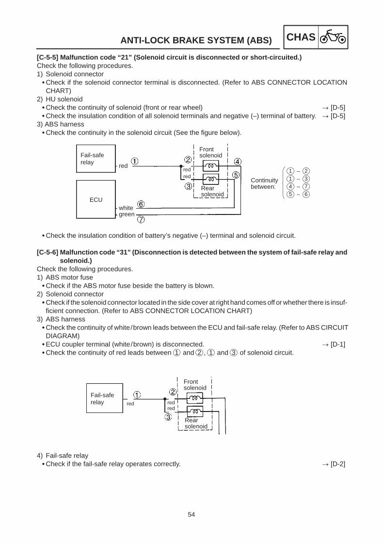
[C-5-5] Malfunction code “21” (Solenoid circuit is disconnected or short-circuited.)Check the following procedures.1) Solenoid connectorCheck if the solenoid connector terminal is disconnected. (Refer to ABS CONNECTOR LOCATION
CHART)2) HU solenoidCheck the continuity of solenoid (front or rear wheel) [D-5]Check the insulation condition of all solenoid terminals and negative (–) terminal of battery. [D-5]
3) ABS harnessCheck the continuity in the solenoid circuit (See the figure below).
Check the insulation condition of battery’s negative (–) terminal and solenoid circuit.
[C-5-6] Malfunction code “31” (Disconnection is detected between the system of fail-safe relay andsolenoid.)
Check the following procedures.1) ABS motor fuseCheck if the ABS motor fuse beside the battery is blown.
2) Solenoid connectorCheck if the solenoid connector located in the side cover at right hand comes off or whether there is insuf-
ficient connection. (Refer to ABS CONNECTOR LOCATION CHART)3) ABS harnessCheck the continuity of white/brown leads between the ECU and fail-safe relay. (Refer to ABS CIRCUIT
DIAGRAM)ECU coupler terminal (white/brown) is disconnected. [D-1]Check the continuity of red leads between 1 and 2 , 1 and 3 of solenoid circuit.
4) Fail-safe relayCheck if the fail-safe relay operates correctly. [D-2]

55
Check the continuity at this point
Terminal B
Terminal A
ANTI-LOCK BRAKE SYSTEM (ABS) CHAS
5) Wire harnessCheck the continuity between the red/blue terminal of fail-safe relay’s coupler and positive (+) terminal of
battery.Remove the ECU fuse and check the continuity between the brown/white lead of fail-safe relay’s con-
nector and ABS fuse (see the illustration below).
[C-5-7] Malfunction code “32” (Detected the operation failure of fail-safe relay)1) Fail-safe relayCheck if the fail-safe relay operates correctly. [D-2]
2) ABS harnessWith the fail-safe relay and ECU removed from the ABS wire harness, check the insulation between the
red/blue and red terminals of the coupler for fail-safe relay.
[C-5-8] Malfunction code “33” (Detected the failure of motor operation (Motor stops and will notrotate))
1) ABS pump fuseCheck if the fuse for ABS motor beside the batter is blown.
2) Fail-safe relayCheck if the fail-safe relay operates correctly. [D-2]
3) Wire harness and the ABS harnessRemove the fail-safe relay and check the continuity between the red terminal of ABS harness and ABS
harness side (A terminal as shown in the figure) of ABS fuse terminal in the fuse box. (Remove the fusefirst.) (Refer to ABS CIRCUIT DIAGRAM.)
Check the continuity between the battery positive (+) terminal and battery side of ABS pump fuse termi-nal (B terminal as shown in the above figure).
Remove the ECU and fail-safe relay from the ABS harness and check the continuity betweenwhite/black lead terminals and between red / white lead terminals.

56
ANTI-LOCK BRAKE SYSTEM (ABS) CHAS
WARNING
WARNING
[C-5-9] Malfunction code “34” (Detected the failure operation of motor (Motor keeps rotating and willnot stop))
1) HU pump motorCheck if the pump motor connector in the left side cover is detached or is insufficiently connected.Check the continuity of motor. [D-5]
2) ABS harnessWith the HU pump motor connector removed, check the continuity between the black terminal of pump
motor connector of ABS harness and battery negative (–) terminal.With the ECU connector removed, check the continuity between the red/white terminal of ECU connec-
tor and red/white terminal of pump motor connector. [D-1]With the fail-safe relay removed, check the continuity between the red/white terminal of pump motor
connector of ABS harness and battery positive (+) terminal.3) Fail-safe relayCheck if the fail-safe relay operates correctly. [D-2]
[C-5-10]Malfunction code “41” (Front wheel will not recover from the locking tendency even thoughthe signal is continuously sent from the ECU to release the hydraulic state (while the batteryvoltage is normal).)
1) Rotation of wheelsCheck there is no brake dragging with the front wheel and it rotates smoothly.Check if there are looseness of bearings, bending of wheel axle or distortion on brake discs.
2) Master cylinder and caliperCheck the brake fluid pressure is correctly transmitted to brake disc when the brake lever is operated and
the pressure is discompressed when the lever is released.3) Brake fluidCheck the brake fluid in the reservoir tank by observing. (Mixing of water, foreign matters, solidification
and contamination)Check if air is mixed in the brake hose line.
4) Brake hose lineCheck if the brake hose line is folded or broken.
Using brake pipes, hoses and union bolts other than genuine YAMAHA parts may close the pipinglines. Do not use them.
Check the connection of brake hose or pipe lines on the master cylinder and caliper sides to the HU arecorrect.
Front wheel side inlet: Brake hose 1 from thefront master cylinderFront wheel side outlet: Brake hose 2 fromthe front brake caliper

57
ANTI-LOCK BRAKE SYSTEM (ABS) CHAS
NOTE:
WARNING
If the inlet and outlet to connect with the HU are mistaken, when the HU operation test is performed which isshown in [D-6], the brake lever enters down to full stroke without responding and will be pushed back slow-ly without pulsation.
If the connection of front and rear side is mistaken, when the HU operation test is performed which isshown in [D-6], the HU operation of front and rear sides will be performed in reverse steps.
5) Solenoid connector terminalCheck if the front and rear solenoid connector terminals (HU and wire harness sides) are reversed.
Terminal color
Solenoid side Wire harness side
Front Red, white Red, white
Rear Red, green Red, green
6) HUIf the problem does not come under any phenomena from 1) to 5), the function failure of hydraulic unit couldbe thought. Replace the hydraulic unit and execute the secure piping and wiring. Check by the HU operationtest as described in [D-6].
[C-5-11]Malfunction code “42” (Rear wheel will not recover from the locking tendency even thoughthe signal is continuously sent from the ECU to release the hydraulic state (while the batteryvoltage is normal.))
1) Rotation of wheelsCheck there is no brake dragging with the rear wheel and it rotates smoothly.Check if there is a distortion on brake discs.
2) Master cylinder and caliperCheck the brake fluid pressure is correctly transmitted to brake disc when the brake lever is operated and
the pressure is discompressed when the lever is released.3) Brake fluidCheck the brake fluid in the reservoir tank by observing. (Mixing of water, foreign matters, solidification
and contamination)Check if air is mixed in the brake hose line.
4) Brake hose lineCheck if the brake hose line is folded or broken. (Particularly between the HU rear caliper)
Using brake pipes, hoses and union bolts other than genuine YAMAHA parts may close the pipinglines. Do not use them.
Check the connection of brake hose or pipe lines on the master cylinder and caliper sides to the HU arecorrect.
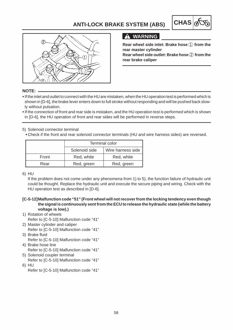
58
ANTI-LOCK BRAKE SYSTEM (ABS) CHAS
WARNING
NOTE:
Rear wheel side inlet: Brake hose 1 from therear master cylinderRear wheel side outlet: Brake hose 2 from therear brake caliper
If the inlet and outlet to connect with the HU are mistaken, when the HU operation test is performed which isshown in [D-6], the brake lever enters down to full stroke without responding and will be pushed back slow-ly without pulsation.
If the connection of front and rear side is mistaken, and the HU operation test is performed which is shownin [D-6], the HU operation of front and rear sides will be performed in reverse steps.
5) Solenoid connector terminalCheck if the front and rear solenoid connector terminals (HU and wire harness sides) are reversed.
Terminal color
Solenoid side Wire harness side
Front Red, white Red, white
Rear Red, green Red, green
6) HUIf the problem does not come under any phenomena from 1) to 5), the function failure of hydraulic unitcould be thought. Replace the hydraulic unit and execute the secure piping and wiring. Check with theHU operation test as described in [D-6].
[C-5-12]Malfunction code “51” (Front wheel will not recover from the locking tendency even thoughthe signal is continuously sent from the ECU to release the hydraulic state (while the batteryvoltage is low).)
1) Rotation of wheelsRefer to [C-5-10] Malfunction code “41”
2) Master cylinder and caliperRefer to [C-5-10] Malfunction code “41”
3) Brake fluidRefer to [C-5-10] Malfunction code “41”
4) Brake hose lineRefer to [C-5-10] Malfunction code “41”
5) Solenoid coupler terminalRefer to [C-5-10] Malfunction code “41”
6) HURefer to [C-5-10] Malfunction code “41”

59
ANTI-LOCK BRAKE SYSTEM (ABS) CHAS
7) Battery voltageMeasure the battery output voltage.
[C-5-13]Malfunction code “52” (Rear wheel will not recover from the locking tendency even thoughthe signal is continuously sent from the ECU to release the hydraulic state (while the batteryvoltage is low).)
1) Rotation of wheelsRefer to [C-5-11] Malfunction code “42”
2) Master cylinder and caliperRefer to [C-5-11] Malfunction code “42”
3) Brake fluidRefer to [C-5-11] Malfunction code “42”
4) Brake hose lineRefer to [C-5-11] Malfunction code “42”
5) Solenoid coupler terminalRefer to [C-5-11] Malfunction code “42”
6) HURefer to [C-5-11] Malfunction code “42”
7) Battery voltageRefer to [C-5-12] Malfunction code “51”
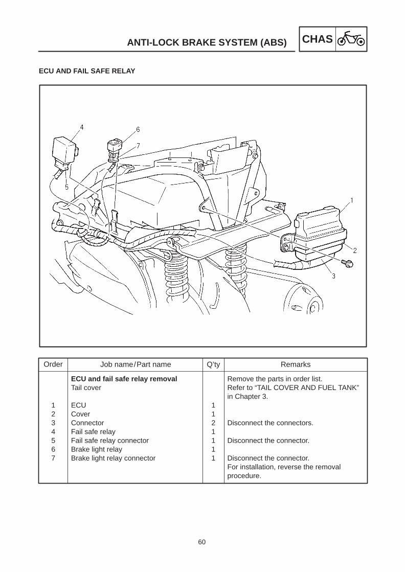
60
Order Job name/Part name Q’ty Remarks
1234567
ECU and fail safe relay removalTail cover
ECUCoverConnectorFail safe relayFail safe relay connectorBrake light relayBrake light relay connector
1121111
Remove the parts in order list.Refer to “TAIL COVER AND FUEL TANK”in Chapter 3.
Disconnect the connectors.
Disconnect the connector.
Disconnect the connector.For installation, reverse the removalprocedure.
ANTI-LOCK BRAKE SYSTEM (ABS) CHAS
ECU AND FAIL SAFE RELAY

61
ANTI-LOCK BRAKE SYSTEM (ABS) CHAS
NOTE:
NOTE:
NOTE:
[D-1] MAINTENANCE FOR ECURemoving the ECU1. Remove:ECU 1
Carefully take out the ECU lead 3 not to damagethe ECU connector and remove the ECU.
2. Remove:ECU connector 1ECU connector 2
To remove the ECU coupler, do not pull the ECUleads.Always press on the lock 3 and remove it.
Checking the ECU1. Check:Terminals 1 of the ECU
Cracks/damages Replace ECUTerminals 2 of the ECU coupler
Connection defective, contaminated, come-off Correct or clean.
If the connector is clogged by mud or dirt, clean itby air blow.
ECU assembly1. Install:ECU 1

62
Connect thebattery toand termi-nal
7
Operation of solenoid relay : Continuity
Terminal number
Normalcondition
8
ANTI-LOCK BRAKE SYSTEM (ABS) CHAS
NOTE:
[D-2] MAINTENANCE OF THE ABS FAIL-SAFERELAYRemoving the fail-safe relay1. Remove:ABS fail-safe relay coupler 1
Do not pull the ABS fail-safe relay leads to removethe ABS fail-safe relay connector.Always press on the lock 2 and remove it.
Checking the fail-safe relay1. Check:Solenoid relay continuity
Connect the pocket tester (Ω 1) to terminals.Check the continuity between the terminal 3and 4 of solenoid relay.Tester’s positive (+) lead Terminal 3Tester’s negative (–) lead Terminal 4If tester reading is “∞”. Replace the fail-saferelay.
Check the continuity between the terminal 7and 8 of solenoid relay.Tester’s positive (+) lead Terminal 7Tester’s negative (–) lead Terminal 8If tester reading is “∞”. Replace the fail-saferelay.
Finally, connect the battery’s positive (+) termi-nal to the terminal 7 of solenoid relay, nega-tive (–) terminal to the terminal 8 , and checkthe continuity between the solenoid terminal4 and 5 .

63
ANTI-LOCK BRAKE SYSTEM (ABS) CHAS
Fail-safe relay
Solenoidrelay
Motorrelay
Connect thebattery toand termi-nal
6
Operation of motor relay : Continuity
Terminal number
Normalcondition
1
CAUTION:
CAUTION:
CAUTION:
Tester’s positive (+) lead Terminal 4Tester’s negative (–) lead Terminal 5If tester reading is “∞”. Replace the fail-saferelay.
When connecting the relay and battery termi-nals, be careful not to short-circuit the bat-tery’s positive (+) and negative (–) terminals.
2. Check:Continuity of motor relay
Connect the pocket tester (Ω 1) to motorrelay terminals.First, check the continuity between the motorrelay terminal 1 and 6 .Tester’s positive (+) lead Terminal 1Tester’s negative (–) lead Terminal 6If tester reading is “∞”. Replace the fail-saferelay.
If the 1 and 6 of tester leads are connectedreverse, it makes the good or bad detectionimpossible. Do not mistake.
Connect the battery positive (+) terminal to theterminal 6 , negative (–) terminal to the terminal1 and check the continuity between motor relayterminals 2 and 5 .Tester’s positive (+) lead Terminal 2Tester’s negative (–) lead Terminal 5If tester reading is “∞”. Replace the fail-saferelay.
If the connection of positive (+), negative (–)is mistaken, the diode will be broken. Con-nect it correctly.
When connecting the battery and relay, becareful not to short-circuit the battery’s posi-tive (+) and negative (–) terminals.
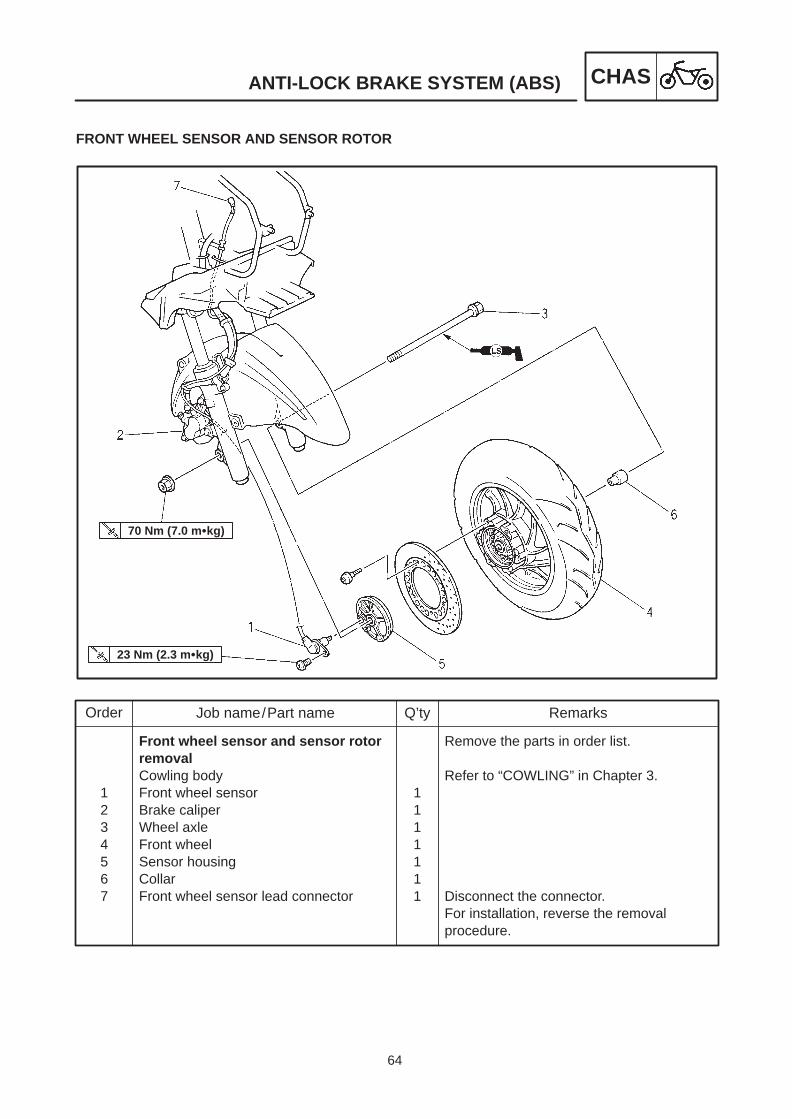
64
Order Job name/Part name Q’ty Remarks
1234567
Front wheel sensor and sensor rotorremovalCowling bodyFront wheel sensorBrake caliperWheel axleFront wheelSensor housingCollarFront wheel sensor lead connector
1111111
Remove the parts in order list.
Refer to “COWLING” in Chapter 3.
Disconnect the connector.For installation, reverse the removalprocedure.
70 Nm (7.0 mkg)
23 Nm (2.3 mkg)
ANTI-LOCK BRAKE SYSTEM (ABS) CHAS
FRONT WHEEL SENSOR AND SENSOR ROTOR

65
ANTI-LOCK BRAKE SYSTEM (ABS) CHAS
CAUTION:
NOTE:
CAUTION:
ABS wheel sensor and the sensor rotor
Care should be taken to handle the ABS com-ponents since they have been accurately ad-justed and set, and must be kept away fromshocks and dirt.
ABS wheel sensor cannot be disassembled.Never disassemble it. If failed, replace with anew one.
[D-3] MAINTENANCE OF THE FRONT WHEELSENSOR AND SENSOR ROTORRemoving the front wheel sensor1. Remove:Clamp 1
Clamp can be easily removed by moving theclamp tip of brake hose and wheel sensor leads upand down.
2. Remove: caliper 1Wheel sensor 2
Care should be taken not to allow the sensorelectrode to contact the metal parts when re-moving the wheel sensor from the wheel hub.
To remove the wheel, do not operate thebrake lever.
Checking the front wheel sensor and the sen-sor rotor1. Check:Front wheel sensor 1
Cracks, bending and distortion ReplaceIron powder and dust Wash
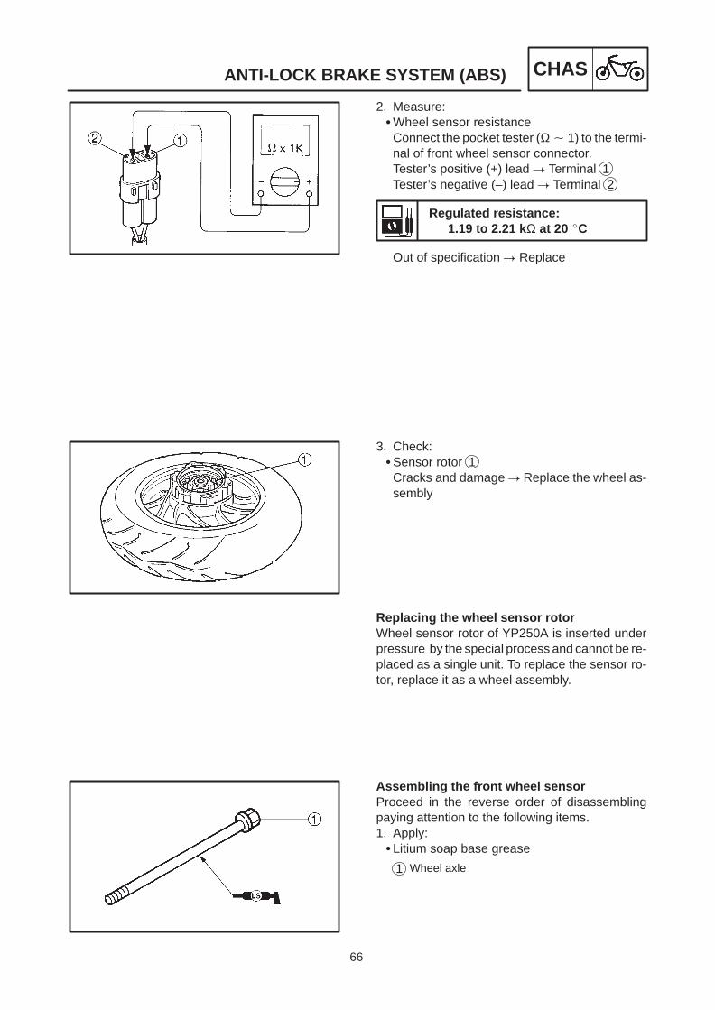
66
ANTI-LOCK BRAKE SYSTEM (ABS) CHAS
2. Measure:Wheel sensor resistance
Connect the pocket tester (Ω 1) to the termi-nal of front wheel sensor connector.Tester’s positive (+) lead Terminal 1Tester’s negative (–) lead Terminal 2
Regulated resistance:1.19 to 2.21 k Ω at 20 C
Out of specification Replace
3. Check:Sensor rotor 1
Cracks and damage Replace the wheel as-sembly
Replacing the wheel sensor rotorWheel sensor rotor of YP250A is inserted underpressure by the special process and cannot be re-placed as a single unit. To replace the sensor ro-tor, replace it as a wheel assembly.
Assembling the front wheel sensorProceed in the reverse order of disassemblingpaying attention to the following items.1. Apply:Litium soap base grease
1 Wheel axle

67
ANTI-LOCK BRAKE SYSTEM (ABS) CHAS
NOTE:
CAUTION:
23 Nm (2.3 mkg)
35 Nm (3.5 mkg)
NOTE:
CAUTION:
2. Install:Sensor housing
3. Install:Front wheel
Align the slot of sensor housing with the projectionpart of front fork, then assemble them.
Install after checking if foreign materials aremixed in the wheel hub. If foreign materials aremixed, it causes to damage the inner sensorrotor and wheel sensor.
5. Install:Front wheel sensor 1Brake caliper 2Clamp 3
When installing the wheel sensor, check if thewheel sensor lead is twisted or foreign matters at-tached to the electrode.
To route the front wheel sensor lead, refer tothe CABLE ROUTING.

68
ANTI-LOCK BRAKE SYSTEM (ABS) CHAS
6. Install:Wheel sensor lead 1
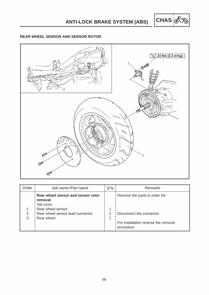
69
Order Job name/Part name Q’ty Remarks
123
Rear wheel sensor and sensor rotorremovalTail coverRear wheel sensorRear wheel sensor lead connectorRear wheel
111
Remove the parts in order list.
Disconnect the connector.
For installation reverse the removalprocedure.
23 Nm (2.3 mkg)
ANTI-LOCK BRAKE SYSTEM (ABS) CHAS
REAR WHEEL SENSOR AND SENSOR ROTOR

70
ANTI-LOCK BRAKE SYSTEM (ABS) CHAS
CAUTION:
[D-4] MAINTENANCE OF THE REAR WHEELSENSOR AND SENSOR ROTORRemoving the rear wheel sensor1. Disconnect:Wheel sensor lead connector 1
2. Remove:Clamp 1
3. Remove:Rear wheel sensor 1
Care should be taken not to allow the sensorelectrode to contact the metal parts when re-moving the wheel sensor from the sensorhousing.
Checking the rear wheel sensor and sensor ro-torRefer to Checking the front wheel sensor and sen-sor rotor.

71
ANTI-LOCK BRAKE SYSTEM (ABS) CHAS
23 Nm (2.3 mkg)
NOTE:
CAUTION:
CAUTION:
Replacing the wheel sensor rotorWheel sensor rotor of YP250A is pressed in by thespecial process and cannot be replaced as asingle unit. To replace the sensor rotor, replace asa wheel assembly.
Assembling the rear wheel sensor1. Install:Rear wheel sensor 1
When installing the wheel sensor, check if thewheel sensor wire is twisted or foreign materialsattached to the electrode.
To route the rear wheel sensor lead, refer to theCABLE ROUTING.
2. Connect:Wheel sensor lead connector 1
To route the rear wheel sensor wire, refer toCABLE ROUTING.

72
Order Job name/Part name Q’ty Remarks
123456789
10
Hydraulic unit removalLower cover, footrest board
Drain the brake fluid.Union bolt /copper washersFront brake hose (OUT)Union bolt /copper washersFront brake hose (IN)Union bolt /copper washersRear brake hose (OUT)Union bolt /copper washersRear brake hose (IN)Hydraulic unitHydraulic unit lead connector
1/21
1/21
1/21
1/2112
Remove the parts in order list.Refer to “FOOTREST BOARD AND LOWERCOVER” in Chapter 3.
(HU-Front brake caliper)
(HU-Front master cylinder)
(HU-Rear brake caliper)
(HU-Rear master cylinder)
Disconnect the connectors.For installation, reverse the removalprocedure.
30 Nm (3.0 mkg)
ANTI-LOCK BRAKE SYSTEM (ABS) CHAS
HYDRAULIC UNIT (HU)

73
ANTI-LOCK BRAKE SYSTEM (ABS) CHAS
CAUTION:
CAUTION:
[D-5] MAINTENANCE OF THE HYDRAULICUNIT (HU)
To check the solenoid resistance of hydraulicunit and continuity of motor, do not remove thehydraulic unit.
Care should be taken to handle the ABS com-ponents since they have been accurately ad-justed and set, and must be kept away fromshocks and dirt.
ABS wheel sensor cannot be disassembled.Never disassemble it. If failed, replace with anew one.
Do not turn the main switch on while remov-ing the hydraulic unit.
Do not clean by flowing air.Do not use the used brake fluid again.Do not mix the brake fluids of different
brands. If the brake fluid is attached to the coated sur-
face or plastics, it may cause the damage. Donot allow it to attach.
If the brake fluid attached the connectors, itmay cause bad contacts. Do not allow it to at-tach.
If the joint parts related to the hydraulic unitare removed, be sure to check tightening onthem and bleed air.

74
ANTI-LOCK BRAKE SYSTEM (ABS) CHAS
Continuity is all right.
Checking 1 the hydraulic unit(Resistance of solenoid valve/Continuity ofmotor)1. Measure:Resistance of solenoid valve (front side)
Connect the pocket tester (Ω 1) to the termi-nal of solenoid valve (front).Tester’s positive (+) lead Terminal 1Tester’s negative (–) lead Terminal 2
Solenoid valve resistance:Less than 10 Ω at 20 C
Out of specification Replace the hydraulicunit
2. Measure:Resistance of solenoid valve (rear side)
Connect the pocket tester (Ω 1) to the termi-nal of solenoid valve (rear).Tester’s negative (–) lead Terminal 1Tester’s positive (+) lead Terminal 2
Solenoid valve resistance:Less than 10 Ω at 20 C
Out of specification Replace the hydraulicunit.
3. Check: Insulation of solenoid valve
Connect the pocket tester (Ω 1k) to the ter-minal of solenoid valve and battery negative (–)terminal.Tester’s positive (+) lead 1 2 3 4Tester’s negative (–) lead Battery negative(–) terminalIf continuity is all right Replace the hydraulicunit.
4. Check:Continuity of the motor (HU)
Connect the pocket tester (Ω 1) to the termi-nal of motor coupler.Tester’s positive (+) lead 1 terminalTester’s negative (–) lead 2 terminal
No continuity Replace the hydraulic unit.
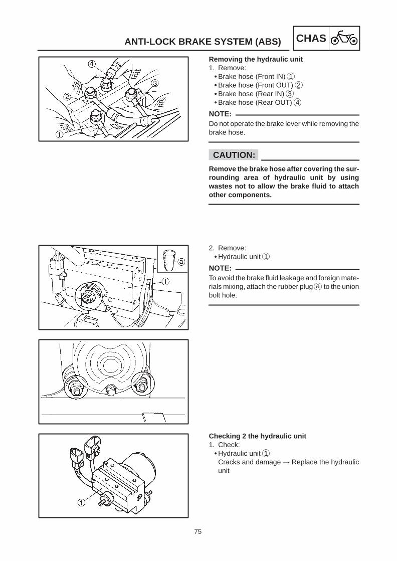
75
ANTI-LOCK BRAKE SYSTEM (ABS) CHAS
NOTE:
CAUTION:
NOTE:
Removing the hydraulic unit1. Remove:Brake hose (Front IN) 1Brake hose (Front OUT) 2Brake hose (Rear IN) 3Brake hose (Rear OUT) 4
Do not operate the brake lever while removing thebrake hose.
Remove the brake hose after covering the sur-rounding area of hydraulic unit by usingwastes not to allow the brake fluid to attachother components.
2. Remove:Hydraulic unit 1
To avoid the brake fluid leakage and foreign mate-rials mixing, attach the rubber plug a to the unionbolt hole.
Checking 2 the hydraulic unit1. Check:Hydraulic unit 1
Cracks and damage Replace the hydraulicunit
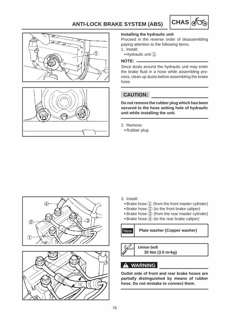
76
ANTI-LOCK BRAKE SYSTEM (ABS) CHAS
NOTE:
CAUTION:
New Plate washer (Copper washer)
WARNING
Installing the hydraulic unitProceed in the reverse order of disassemblingpaying attention to the following items.1. Install:Hydraulic unit 1
Since dusts around the hydraulic unit may enterthe brake fluid in a hose while assembling pro-cess, clean up dusts before assembling the brakehose.
Do not remove the rubber plug which has beensecured to the hose setting hole of hydraulicunit while installing the unit.
2. Remove:Rubber plug
3. Install:Brake hose 1 (from the front master cylinder)Brake hose 2 (to the front brake caliper)Brake hose 3 (from the rear master cylinder)Brake hose 4 (to the rear brake caliper)
Union bolt30 Nm (3.0 mkg)
Outlet side of front and rear brake hoses arepartially distinguished by means of rubberhose. Do not mistake to connect them.
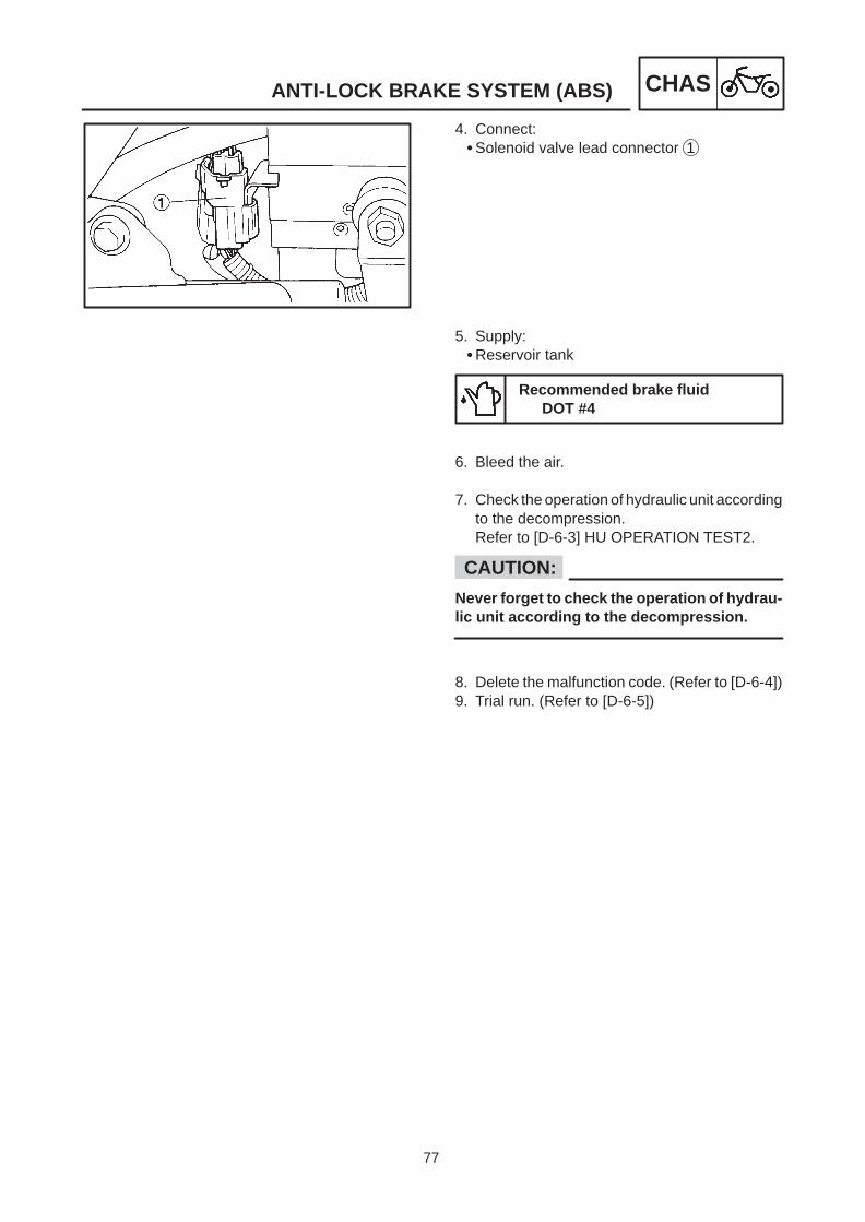
77
ANTI-LOCK BRAKE SYSTEM (ABS) CHAS
CAUTION:
4. Connect:Solenoid valve lead connector 1
5. Supply:Reservoir tank
Recommended brake fluidDOT #4
6. Bleed the air.
7. Check the operation of hydraulic unit accordingto the decompression.Refer to [D-6-3] HU OPERATION TEST2.
Never forget to check the operation of hydrau-lic unit according to the decompression.
8. Delete the malfunction code. (Refer to [D-6-4])9. Trial run. (Refer to [D-6-5])

78
ANTI-LOCK BRAKE SYSTEM (ABS) CHAS
WARNING
CAUTION:
AIR BLEEDING (ABS brake system)
Always bleed air when the brake related partsare removed.
Bleed air following these steps.a 1st step: Front brake caliperb 2nd step: Rear brake caliper
Front brake lever 1Rear brake lever 2
3 Front brake hose (IN)4 Rear brake hose (IN)
CHECK THE OPERATION OF HYDRAULICUNIT ACCORDING TO THE DECOMPRESSION1. Check the operation by decompression.
Refer to [D-6-3] HU OPERATION TEST2.
[D-6] FINAL CHECKChecking procedures1. Check the reservoir tank fluid level2. Recheck the assembly status of wheel sensors3. HU operation test4. Deleting the malfunction codes5. Trial run
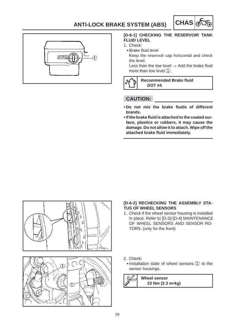
79
ANTI-LOCK BRAKE SYSTEM (ABS) CHAS
CAUTION:
[D-6-1] CHECKING THE RESERVOIR TANKFLUID LEVEL1. Check:Brake fluid level
Keep the reservoir cap horizontal and checkthe level.Less than the low level Add the brake fluidmore than low level 1 .
Recommended Brake fluidDOT #4
Do not mix the brake fluids of differentbrands.
If the brake fluid is attached to the coated sur-face, plastics or rubbers, it may cause thedamage. Do not allow it to attach. Wipe off theattached brake fluid immediately.
[D-6-2] RECHECKING THE ASSEMBLY STA-TUS OF WHEEL SENSORS1. Check if the wheel sensor housing is installed
in place. Refer to [D-3]/ [D-4] MAINTENANCEOF WHEEL SENSORS AND SENSOR RO-TORS. (only for the front)
2. Check: Installation state of wheel sensors 1 to the
sensor housings.
Wheel sensor23 Nm (2.3 mkg)

80
ANTI-LOCK BRAKE SYSTEM (ABS) CHAS
WARNING
NOTE:
[D-6-3] HU OPERATION TEST 2
Be careful to prevent the scooter from fallingdown.
1. Move the scooter to the flat place and use thecenterstand.
2. Remove:Battery case cover
3. Check:Battery terminal voltage
Battery terminal voltageHigher than 12.8V.
If it is lower than 12.8V; Charge or replacethe battery.
If the battery terminal voltage is lower than 12.8V,charge and perform the test.
If the battery terminal voltage is lower than 10V,the “ABS” warning light goes on and the ECUstops the operation of ABS.
4. Connect the test coupler adapter 1 to the testconnector 2 . Refer to [B-5].

81
ANTI-LOCK BRAKE SYSTEM (ABS) CHAS
Mainswitch
ON
ON
OFF
Flashing
2.0se-conds
3.0seconds
0.5se-conds
0.5se-conds
0.5se-conds
0.5se-conds
ABSwarning light
motor
HU operation
2.0seconds
3.0seconds
1.5seconds
0.5seconds
0.5seconds
1.0seconds
OFF
NOTE:
CAUTION:
5. Turn the main switch to “ON” while operatingthe front brake and rear brake levers simulta-neously.
When turning the main switch on, it is impossibleto check unless the both front brake and rearbrake levers are operated simultaneously.
Works should be done by two operators.
6. Check:HU operation
When the main switch is turned on, the ABSwarning light goes on for 2 seconds and startsflashing 3 seconds later.
At the same time it starts flashing, the frontbrake lever 1 will be returned instantaneous-ly. Then, the rear brake lever 2 will be also re-turned instantaneously.
Ensure that the front brake lever is returned,then the rear brake in order.
If the order is reversed as the rear brake leverand front brake lever, recheck the hydrauliccircuit.
If the lever returns slowly not instantaneous-ly, the brake hose may be connected with theinlet and outlet reversed.
When the HU operation is completely correctly,delete all malfunction codes.

82
ANTI-LOCK BRAKE SYSTEM (ABS) CHAS
CAUTION:
NOTE:
[D-6-4] DELETING THE MALFUNCTION CODE1. Connect the test coupler adapter 1 to the test
connector 2 . Refer to [B-5].
2. Turn the main switch on.Previously recorded malfunction code is dis-played by the ABS warning light.
3. Turn the engine stop switch 1 off.
If the starter switch is pushed without turningthe engine stop switch off, it may damage thestarting motor gears or other parts, thereforebe sure to turn it off.
4. Push the starter switch 2 more than 10 timesin 4 seconds, applying the front or rear brakelever.
ABS warning light goes on when the starter switchis pushed, but this state is normal.
5. Check that the ABS warning light keeps flash-ing.
6. Turn the main switch off.
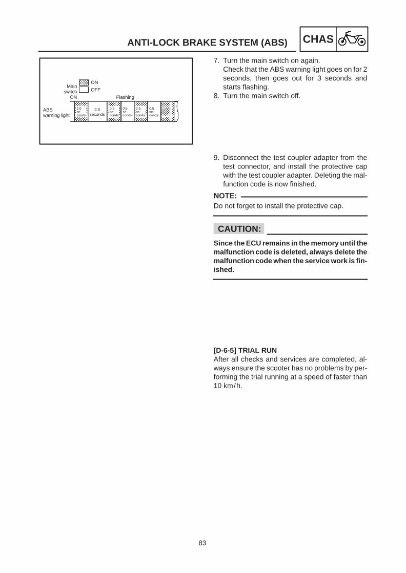
83
ANTI-LOCK BRAKE SYSTEM (ABS) CHAS
Mainswitch
ON
ON
OFF
Flashing
2.0se-conds
3.0seconds
0.5se-conds
0.5se-conds
0.5se-conds
0.5se-conds
ABSwarning light
NOTE:
CAUTION:
7. Turn the main switch on again.Check that the ABS warning light goes on for 2seconds, then goes out for 3 seconds andstarts flashing.
8. Turn the main switch off.
9. Disconnect the test coupler adapter from thetest connector, and install the protective capwith the test coupler adapter. Deleting the mal-function code is now finished.
Do not forget to install the protective cap.
Since the ECU remains in the memory until themalfunction code is deleted, always delete themalfunction code when the service work is fin-ished.
[D-6-5] TRIAL RUNAfter all checks and services are completed, al-ways ensure the scooter has no problems by per-forming the trial running at a speed of faster than10 km/h.

84
REAR SHOCK ABSORBER AND SWING ARM CHAS
Order Job name/Part name Q’ty Remarks
123
456789
Rear shock absorber and swingarmremovalSide panels
BoxNutMuffler assembly
Axle nutRear shock absorberSwingarmCollarOil sealBearing
121
111111
Remove the parts in order.
Refer to “COVER AND PANEL” section inCHAPTER 3.
Loosen.
Remove with the rear brake applied.
Reverse the removal procedure forinstallation.
NOTE:
NOTE:
40 Nm (4.0 mkg)
19 Nm (1.9 mkg)
135 Nm (13.5 mkg)
7 Nm (0.7 mkg)
20 Nm (2.0 mkg)
30 Nm (3.0 mkg)
20 Nm (2.0 mkg)
53 Nm (5.3 mkg)
REAR SHOCK ABSORBER AND SWING ARM
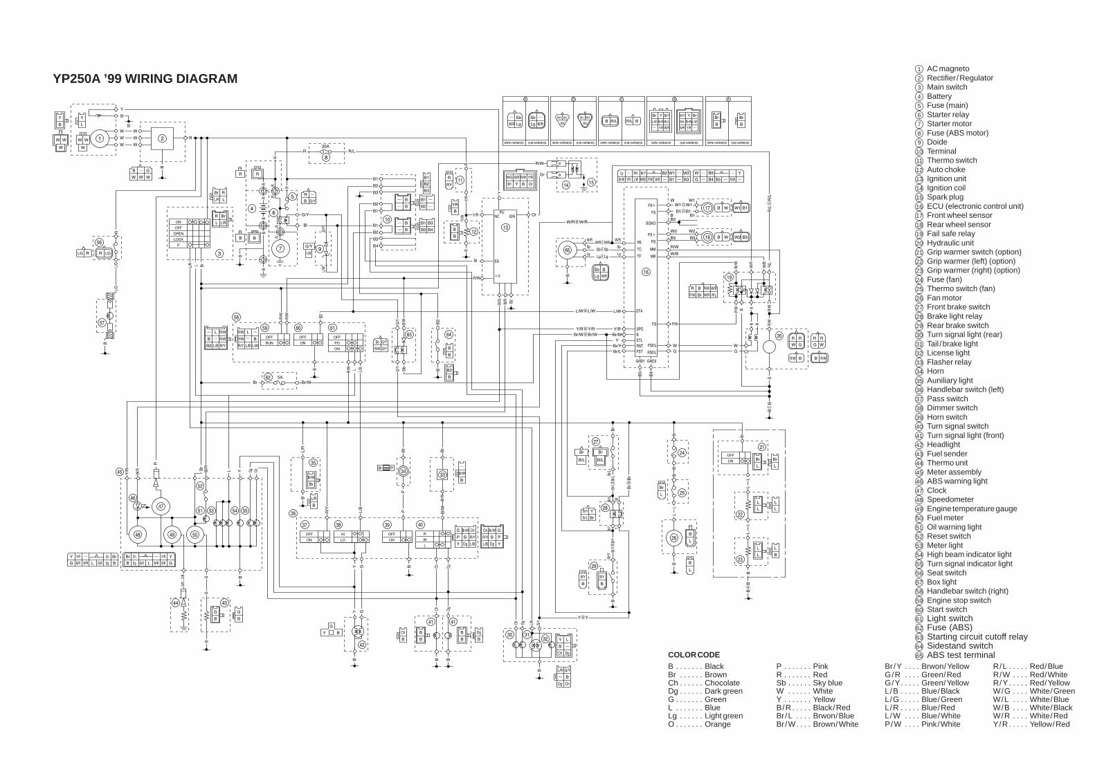
COLOR CODEB Black. . . . . . . Br Brown. . . . . . Ch Chocolate. . . . . . Dg Dark green. . . . . . G Green. . . . . . . L Blue. . . . . . . Lg Light green. . . . . . O Orange. . . . . . .
P Pink. . . . . . . R Red. . . . . . . Sb Sky blue. . . . . . W White. . . . . . Y Yellow. . . . . . . B/R Black/Red. . . . . Br/L Brwon/Blue. . . . Br/W Brown/White. . . .
Br/Y Brwon/Yellow. . . . G/R Green/Red. . . . G/Y Green/Yellow. . . . . L/B Blue/Black. . . . . L/G Blue/Green. . . . . L/R Blue/Red. . . . . L/W Blue/White. . . . P/W Pink/White. . . .
R/L Red/Blue. . . . . R/W Red/White. . . . R/Y Red/Yellow. . . . . W/G White/Green. . . . W/L White/Blue. . . . W/B White/Black. . . . W/R White/Red. . . . Y/R Yellow/Red. . . . .
1 AC magneto2 Rectifier/Regulator3 Main switch4 Battery5 Fuse (main)6 Starter relay7 Starter motor8 Fuse (ABS motor)9 Doide10 Terminal11 Thermo switch12 Auto choke13 Ignition unit14 Ignition coil15 Spark plug16 ECU (electronic control unit)17 Front wheel sensor18 Rear wheel sensor19 Fail safe relay20 Hydraulic unit21 Grip warmer switch (option)22 Grip warmer (left) (option)23 Grip warmer (right) (option)24 Fuse (fan)25 Thermo switch (fan)26 Fan motor27 Front brake switch28 Brake light relay29 Rear brake switch30 Turn signal light (rear)31 Tail /brake light32 License light33 Flasher relay34 Horn35 Auniliary light36 Handlebar switch (left)37 Pass switch38 Dimmer switch39 Horn switch40 Turn signal switch41 Turn signal light (front)42 Headlight43 Fuel sender44 Thermo unit45 Meter assembly46 ABS warning light47 Clock48 Speedometer49 Engine temperature gauge50 Fuel meter51 Oil warning light52 Reset switch53 Meter light54 High beam indicator light55 Turn signal indicator light56 Seat switch57 Box light58 Handlebar switch (right)59 Engine stop switch60 Start switch61 Light switch62 Fuse (ABS)63 Starting circuit cutoff relay64 Sidestand switch65 ABS test terminal
YP250A ’99 WIRING DIAGRAM