formacion audi
TRANSCRIPT

32
5
Service TrainingVorsprung durch Technik www.audi.co.uk
All rights reserved. Subject to technical change.
CopyrightAUDI AGI/[email protected] +49-841/89-36367
AUDI AGD-85045 IngolstadtTechnical release 01/04
Printed in GermanyA04.5S00.08.20
AUDI A6 ‘05 Assemblies
Self-Study Programme 325
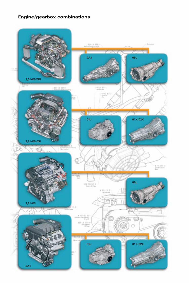
Engine/gearbox combinations
3,0 l-V6-TDI
3,2 l-V6-FSI
4,2 l-V5
2,4 l
01J
09L
01J 01X/02X
09L0A3
01X/02X

Contents
Introduction. . . . . . . . . . . . . . . . . . . . . . . . . . . . . . . . . . . . . . . . . . . . . . . . . . . . . . . . . . . 6
Technical data. . . . . . . . . . . . . . . . . . . . . . . . . . . . . . . . . . . . . . . . . . . . . . . . . . . . . . . . . 7
Mechanics – Crankcase/Crank drive/Oil pump . . . . . . . . . . . . . . . . . . . . . . . . . . . . . 8
Cylinder head . . . . . . . . . . . . . . . . . . . . . . . . . . . . . . . . . . . . . . . . . . . . . . . . . . . . . . . .10
Chain drive . . . . . . . . . . . . . . . . . . . . . . . . . . . . . . . . . . . . . . . . . . . . . . . . . . . . . . . . . .12
Air intake . . . . . . . . . . . . . . . . . . . . . . . . . . . . . . . . . . . . . . . . . . . . . . . . . . . . . . . . . . . .13
VTG turbocharger . . . . . . . . . . . . . . . . . . . . . . . . . . . . . . . . . . . . . . . . . . . . . . . . . . . .15
Exhaust gas recirculation . . . . . . . . . . . . . . . . . . . . . . . . . . . . . . . . . . . . . . . . . . . . . .15
Exhaust system . . . . . . . . . . . . . . . . . . . . . . . . . . . . . . . . . . . . . . . . . . . . . . . . . . . . . .16
Oxygen sensing . . . . . . . . . . . . . . . . . . . . . . . . . . . . . . . . . . . . . . . . . . . . . . . . . . . . . .17
Pre-heating system . . . . . . . . . . . . . . . . . . . . . . . . . . . . . . . . . . . . . . . . . . . . . . . . . . .17
Fuel supply – 3rd generation common rail . . . . . . . . . . . . . . . . . . . . . . . . . . . . . . .18
Piezo injector . . . . . . . . . . . . . . . . . . . . . . . . . . . . . . . . . . . . . . . . . . . . . . . . . . . . . . . .21
Particle filter . . . . . . . . . . . . . . . . . . . . . . . . . . . . . . . . . . . . . . . . . . . . . . . . . . . . . . . . .24
Engine management/System overview . . . . . . . . . . . . . . . . . . . . . . . . . . . . . . . . . .26
Function diagram. . . . . . . . . . . . . . . . . . . . . . . . . . . . . . . . . . . . . . . . . . . . . . . . . . . . .28
3,0 l-V6-TDI-Motor mit Common-Rail-Einspritzung3.0 l V6
3.2 l V6 FSI engine
Introduction. . . . . . . . . . . . . . . . . . . . . . . . . . . . . . . . . . . . . . . . . . . . . . . . . . . . . . . . . .30
Technical data. . . . . . . . . . . . . . . . . . . . . . . . . . . . . . . . . . . . . . . . . . . . . . . . . . . . . . . .31
Mechanics – Crankcase and crankshaft assembly . . . . . . . . . . . . . . . . . . . . . . . .32
Engine ventilation . . . . . . . . . . . . . . . . . . . . . . . . . . . . . . . . . . . . . . . . . . . . . . . . . . . .34
Oil supply. . . . . . . . . . . . . . . . . . . . . . . . . . . . . . . . . . . . . . . . . . . . . . . . . . . . . . . . . . . .35
Engine control – Chain drive . . . . . . . . . . . . . . . . . . . . . . . . . . . . . . . . . . . . . . . . . . .36
Cylinder head . . . . . . . . . . . . . . . . . . . . . . . . . . . . . . . . . . . . . . . . . . . . . . . . . . . . . . . .37
Camshaft adjusters . . . . . . . . . . . . . . . . . . . . . . . . . . . . . . . . . . . . . . . . . . . . . . . . . . .38
Intake system . . . . . . . . . . . . . . . . . . . . . . . . . . . . . . . . . . . . . . . . . . . . . . . . . . . . . . . .39
Exhaust system . . . . . . . . . . . . . . . . . . . . . . . . . . . . . . . . . . . . . . . . . . . . . . . . . . . . . .41
Fuel supply . . . . . . . . . . . . . . . . . . . . . . . . . . . . . . . . . . . . . . . . . . . . . . . . . . . . . . . . . .42
FSI operating methods . . . . . . . . . . . . . . . . . . . . . . . . . . . . . . . . . . . . . . . . . . . . . . . .45
Engine management/System overview . . . . . . . . . . . . . . . . . . . . . . . . . . . . . . . . . .46
Function diagram. . . . . . . . . . . . . . . . . . . . . . . . . . . . . . . . . . . . . . . . . . . . . . . . . . . . .48
Special tools . . . . . . . . . . . . . . . . . . . . . . . . . . . . . . . . . . . . . . . . . . . . . . . . . . . . . . . . .50
The Self-Study Programme provides information on the fundamentals of design and function of new vehicle models, new vehicle components or new technologies.
The Self-Study Programme is not a Workshop Manual!Specified values serve only to make the information easier to understand and relate to the software version that was valid at the time the Self-Study Programme (SSP) was created.
For maintenance and repair work, please make sure to use the current technical documentation.
NoteReference

Introduction . . . . . . . . . . . . . . . . . . . . . . . . . . . . . . . . . . . . . . . . . . . . . . . . . . . . . . . . .52
Technical data. . . . . . . . . . . . . . . . . . . . . . . . . . . . . . . . . . . . . . . . . . . . . . . . . . . . . . . .53
Brief description of 0A3 gearbox . . . . . . . . . . . . . . . . . . . . . . . . . . . . . . . . . . . . . . .54
Brief description of the 01X/02X gearbox . . . . . . . . . . . . . . . . . . . . . . . . . . . . . . . .56
01X/02X bearings . . . . . . . . . . . . . . . . . . . . . . . . . . . . . . . . . . . . . . . . . . . . . . . . . . . . .58
0A3 bearings. . . . . . . . . . . . . . . . . . . . . . . . . . . . . . . . . . . . . . . . . . . . . . . . . . . . . . . . .59
01X/02X lubrication . . . . . . . . . . . . . . . . . . . . . . . . . . . . . . . . . . . . . . . . . . . . . . . . . . .60
0A3 lubrication . . . . . . . . . . . . . . . . . . . . . . . . . . . . . . . . . . . . . . . . . . . . . . . . . . . . . . .62
Inner gearshift . . . . . . . . . . . . . . . . . . . . . . . . . . . . . . . . . . . . . . . . . . . . . . . . . . . . . . .64
0A3 synchronisation . . . . . . . . . . . . . . . . . . . . . . . . . . . . . . . . . . . . . . . . . . . . . . . . . .66
01X and 02X synchronisation . . . . . . . . . . . . . . . . . . . . . . . . . . . . . . . . . . . . . . . . . .67
Gear selector (outer gearshift) . . . . . . . . . . . . . . . . . . . . . . . . . . . . . . . . . . . . . . . . . .68
Gearbox – manual transmission
Gearbox – automatic transmission
Introduction . . . . . . . . . . . . . . . . . . . . . . . . . . . . . . . . . . . . . . . . . . . . . . . . . . . . . . . . .70
Gear selector. . . . . . . . . . . . . . . . . . . . . . . . . . . . . . . . . . . . . . . . . . . . . . . . . . . . . . . . .71
Selector lever locks . . . . . . . . . . . . . . . . . . . . . . . . . . . . . . . . . . . . . . . . . . . . . . . . . . .72
Emergency release. . . . . . . . . . . . . . . . . . . . . . . . . . . . . . . . . . . . . . . . . . . . . . . . . . . .73
Selector lever positioning/Display unit . . . . . . . . . . . . . . . . . . . . . . . . . . . . . . . . . .74
Ignition key anti-removal lock . . . . . . . . . . . . . . . . . . . . . . . . . . . . . . . . . . . . . . . . . .75
Steering wheel Tiptronic. . . . . . . . . . . . . . . . . . . . . . . . . . . . . . . . . . . . . . . . . . . . . . .76
6-gear automatic transmission 09L . . . . . . . . . . . . . . . . . . . . . . . . . . . . . . . . . . . . .77
6-gear automatic gearbox 09L . . . . . . . . . . . . . . . . . . . . . . . . . . . . . . . . . . . . . . . . .78
Technical data. . . . . . . . . . . . . . . . . . . . . . . . . . . . . . . . . . . . . . . . . . . . . . . . . . . . . . . .80
Converter clutch. . . . . . . . . . . . . . . . . . . . . . . . . . . . . . . . . . . . . . . . . . . . . . . . . . . . . .81
Oil management and lubrication . . . . . . . . . . . . . . . . . . . . . . . . . . . . . . . . . . . . . . .82
Function diagram for 09L gearbox . . . . . . . . . . . . . . . . . . . . . . . . . . . . . . . . . . . . . .83
Transmission ratio/Hydraulics (lubrication) . . . . . . . . . . . . . . . . . . . . . . . . . . . . . . .84
Dynamic switching programme – DSP . . . . . . . . . . . . . . . . . . . . . . . . . . . . . . . . . .85
Electro-hydraulic control. . . . . . . . . . . . . . . . . . . . . . . . . . . . . . . . . . . . . . . . . . . . . . .85
Multitronic 01J . . . . . . . . . . . . . . . . . . . . . . . . . . . . . . . . . . . . . . . . . . . . . . . . . . . . . . .86
Combination with the 3.2 l V6 FSI engine . . . . . . . . . . . . . . . . . . . . . . . . . . . . . . . .86
New features – measures. . . . . . . . . . . . . . . . . . . . . . . . . . . . . . . . . . . . . . . . . . . . . .86
Vane-type pump . . . . . . . . . . . . . . . . . . . . . . . . . . . . . . . . . . . . . . . . . . . . . . . . . . . . . .88
Tiptronic /Dynamic Regulating Programme DRP . . . . . . . . . . . . . . . . . . . . . . . . .89
Hill starts . . . . . . . . . . . . . . . . . . . . . . . . . . . . . . . . . . . . . . . . . . . . . . . . . . . . . . . . . . . .89
Function diagram for 01J multitronic . . . . . . . . . . . . . . . . . . . . . . . . . . . . . . . . . . .90

6
3.0 l V6 TDI engine with common-rail injection
Introduction
With the 3.0 l V6 TDI engine with common rail, Audi has introduced the fourth engine in the new generation of V engines.
Its dimensions and its total weight of approx. 220 kg make it one of the lightest and most compact V6 diesel engines around.
325_001
7
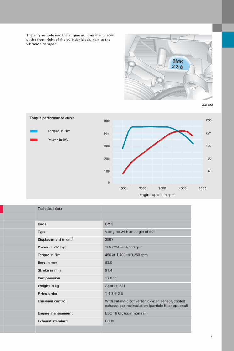
The engine code and the engine number are located at the front right of the cylinder block, next to the vibration damper.
325_013
BMK3 3 83 3 8BMK
300
Nm
100
200
500
120
40
200
kW
1000 2000 3000 4000 5000
80
0
Technical data
Code BMK
Type V engine with an angle of 90°
Displacement in cm3 2967
Power in kW (hp) 165 (224) at 4,000 rpm
Torque in Nm 450 at 1,400 to 3,250 rpm
Bore in mm 83.0
Stroke in mm 91.4
Compression 17.0 : 1
Weight in kg Approx. 221
Firing order 1-4-3-6-2-5
Emission control With catalytic converter, oxygen sensor, cooled exhaust gas recirculation (particle filter optional)
Engine management EDC 16 CP, (common rail)
Exhaust standard EU IV
Torque performance curve
Torque in Nm
Power in kW
Engine speed in rpm

8
3.0 l V6 TDI engine with common-rail injection
Mechanics
Crankcase
The engine block is made of GGV-40 (vermicular graphite cast iron) with a cylinder gap of 90 mm (previously 88 mm).
The cylinder bores undergo UV-photon honing for friction optimisation and in order to minimise initial oil consumption. (Note on page 7)
Crank drive
The crankshaft, which is forged from temper-har-dened steel, is mounted in four places in a main bearing frame.
Industrially cracked trapezoid con-rods are screwed to the crankshaft using a sputtered bearing at the top and a 3-material bearing at the bottom.
325_005
325_030
Piston
A cast piston without valve pockets and with a centrally arranged piston trough is cooled with injection oil via a ring channel (as for 3.3 l V8 CR).
325_032
9
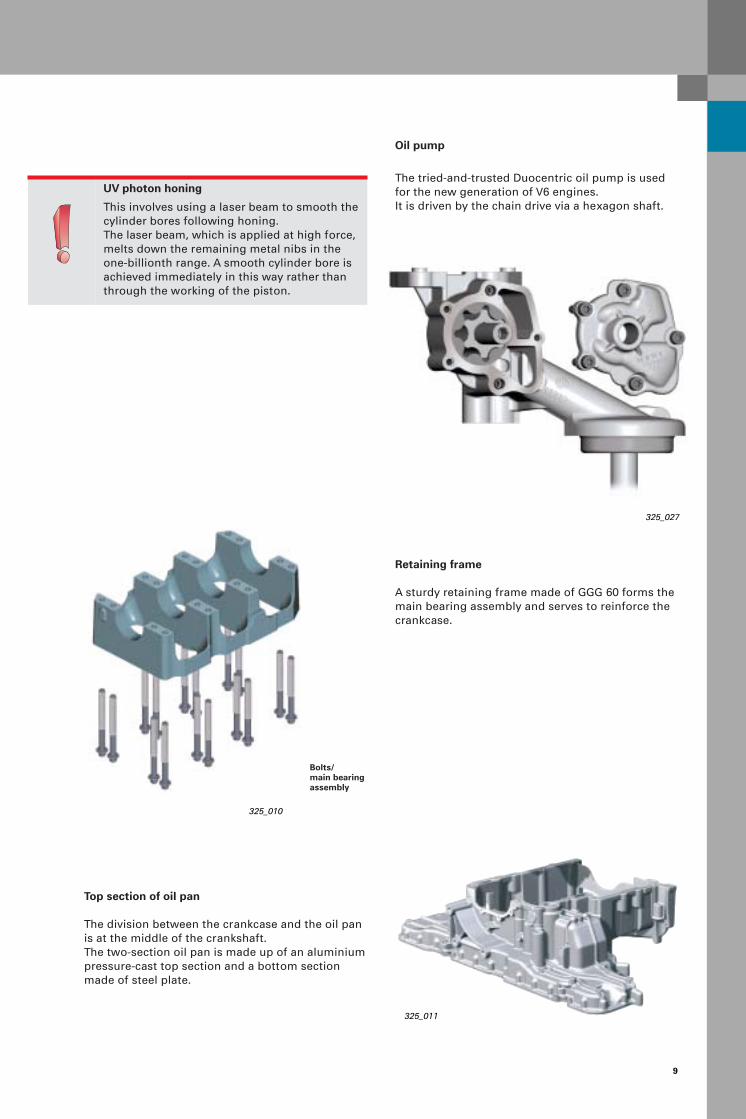
UV photon honing
This involves using a laser beam to smooth the cylinder bores following honing. The laser beam, which is applied at high force, melts down the remaining metal nibs in the one-billionth range. A smooth cylinder bore is achieved immediately in this way rather than through the working of the piston.
Top section of oil pan
The division between the crankcase and the oil pan is at the middle of the crankshaft.The two-section oil pan is made up of an aluminium pressure-cast top section and a bottom section made of steel plate.
Retaining frame
A sturdy retaining frame made of GGG 60 forms the main bearing assembly and serves to reinforce the crankcase.
Oil pump
The tried-and-trusted Duocentric oil pump is used for the new generation of V6 engines.It is driven by the chain drive via a hexagon shaft.
325_010
325_011
325_027
Bolts/main bearingassembly
10
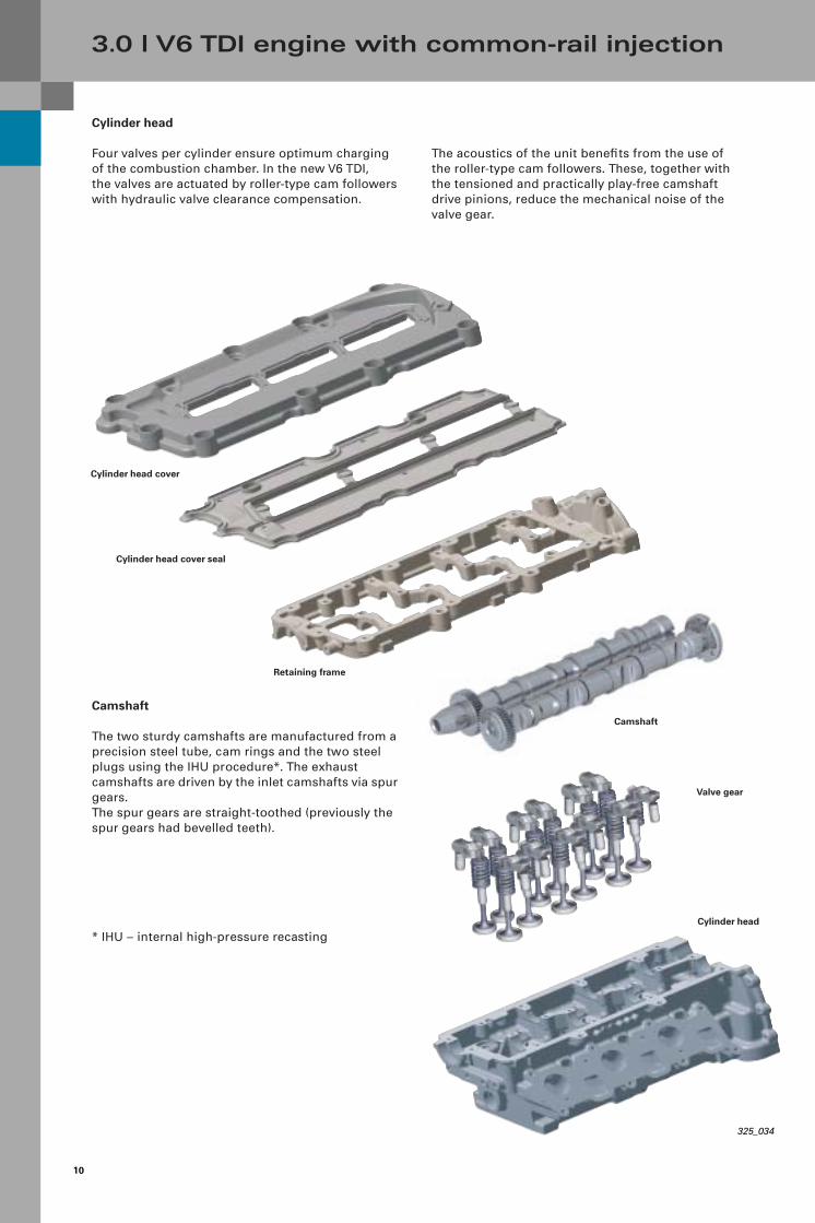
The acoustics of the unit benefits from the use of the roller-type cam followers. These, together with the tensioned and practically play-free camshaft drive pinions, reduce the mechanical noise of the valve gear.
Cylinder head
Four valves per cylinder ensure optimum charging of the combustion chamber. In the new V6 TDI, the valves are actuated by roller-type cam followers with hydraulic valve clearance compensation.
Camshaft
The two sturdy camshafts are manufactured from a precision steel tube, cam rings and the two steel plugs using the IHU procedure*. The exhaust camshafts are driven by the inlet camshafts via spur gears.The spur gears are straight-toothed (previously the spur gears had bevelled teeth).
* IHU – internal high-pressure recasting
3.0 l V6 TDI engine with common-rail injection
Camshaft
Retaining frame
Cylinder head cover
Cylinder head cover seal
Cylinder head
Valve gear
325_034
11
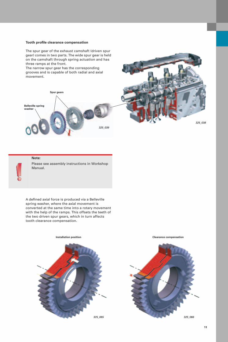
Tooth profile clearance compensation
The spur gear of the exhaust camshaft (driven spur gear) comes in two parts. The wide spur gear is held on the camshaft through spring actuation and has three ramps at the front. The narrow spur gear has the corresponding grooves and is capable of both radial and axial movement.
325_066
Installation position Clearance compensation
325_038
325_039
Note:
Please see assembly instructions in Workshop Manual.
A defined axial force is produced via a Belleville spring washer, where the axial movement isconverted at the same time into a rotary movement with the help of the ramps. This offsets the teeth of the two driven spur gears, which in turn affects tooth clearance compensation.
325_065
Spur gears
Belleville spring washer

12
Chain drive
The new drive generation of V engines is implemented via chain drives and thus replaces the toothed belt. This has made it possible to use a shorter engine type for a wider range of possible applications in various models.
The chain drive is designed as a simplex bush chain (single chain) and is fitted at the gearbox side.It is made up of a central chain (drive A) running from the crankshaft to the intermediate sprockets and a chain to the inlet-side camshaft of both the left and right cylinder heads (drive B + C). And on a second level, from the crankshaft to the oil pump drive and the balancer shaft (drive D).
A separate hydraulic, spring-supported chain tensioner with the required chain guides is fitted for each chain drive. Advantage: Maintenance-free and designed for the service life of the engine.
3.0 l V6 TDI engine with common-rail injection
Camshaft drive – drive BBank 1
Oil pump drive
Balancer shaft drive
Crankshaft drive
Camshaft drive – drive CBank 2
Central chain drive – drive A
Second chain drive – drive D
325_033
Balancer shaft
The new feature here is that the balancer shaft is accommodated in the inner V of the engine block, where the shaft goes through the engine and the balancing weights are secured at the ends.
Driven by chain drive D, the balancer shaft turns at crankshaft speed against the direction of rotation of the engine.
325_076
Balance weights
Balancer shaft drive

13
Intake pipe
Electric butterfly valve adjusterButterfly valves
Throttle position adjuster
325_031
Throttle position adjuster:
The throttle is closed in order to stop the engine.This reduces the compression effect and achieves softer engine coasting.In addition, the exhaust gas recirculation rate can be increased through targeted, map-controlled closure.
Exhaust gas recirculation unit
Exhaust gas recirculation:
This involves high-pressure exhaust gas recirculation.The entry of exhaust gasses into the intake tract counters the intake air flow. This results in a constant mixture of fresh air and exhaust gas.
Exhaust gas recirculation flow
Intake air
Note:
The throttle and butterfly valves are opened in coasting mode in order to check the air flow sensor and balance the oxygen sensor.
The butterfly valve adjuster with potentiometer reports the current position of the butterfly valve back to the engine control unit.
Air intake
Intake manifold with butterfly valves
Butterfly valves that can be regulated smoothly are integrated into the intake tract. These can be used to adapt the air movement according to the current engine speed and load with regard to emissions, consumption and torque/power.

14
Intake manifold with electric adjuster for controlling the butterfly valves
3.0 l V6 TDI engine with common-rail injection
Butterfly valve closed
325_048325_047
Butterfly valve open
To optimise the torque and combustion, a closed swirl duct increases the swirl at low loads.
When the engine is started, the butterfly valves are open and are only closed again at idle speed (duty cycle: approx. 80 %).Continuous opening is performed from idle speed to approx. 2,750 rpm (duty cycle: approx. 20 %).
To optimise performance and combustion, an open swirl duct allows a high level of cylinder charging at high loads.
The butterfly valves are always completely open at a speed of approx. 2,750 rpm or higher.The butterfly valve is also open both at idle speed and during coasting.
Tangential pipe
Swirl duct
Note:
When the adjuster is replaced, it must be adapted to suit the butterfly valves.The valve body must also be replaced when the adjuster is replaced from another engine.

15
Electric adjuster
Air guide vane adjustment
325_026
Exhaust gas recirculation
To achieve a high exhaust gas recirculation flow, a vacuum-controlled exhaust gas recirculation valve is installed. This controls the quantity of exhaust gas recirculated in the intake tract.
To effectively reduce the particle and nitric oxide (NOx) emissions, the exhaust gasses are cooled by a switchable, water-filled exhaust gas recirculation cooler when the engine is warm.
325_035
Note:
Turbocharger adjustment is performed in a con-trolled way at:– a low load and low speed in order to build up the boost pressure quickly.
Regulated at:– a high load and high speed in order to maintain the boost pressure at the optimum range.
VTG turbocharger, electrically adjustable
To guarantee a fast response from the turbocharger at low speeds, air guide vane adjustment has been implemented using an electric adjuster.This allows the exact positioning of the air guide vane to achieve optimum boost pressure.
In addition, a temperature sensor is integrated in front of the turbine in the turbine housing.This measures the boost air temperature andprevents the turbocharger from overheatingby activating engine management. This is also used to initiate the regenerationof the particle filter if the measured temperatureis 450 °C or higher.The connection for exhaust gas recirculationis located in the downpipe, which joins the two cylinder banks on the exhaust side.This involves high-pressure exhaust gas recircula-tion. This means that the exhaust gas recirculation pressure is always higher than the intake pipepressure.
Temperature sensor
16
3.0 l V6 TDI engine with common-rail injection
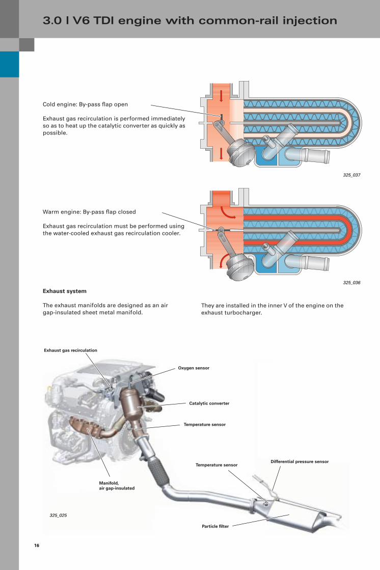
Warm engine: By-pass flap closed
Exhaust gas recirculation must be performed using the water-cooled exhaust gas recirculation cooler.
325_037
Cold engine: By-pass flap open
Exhaust gas recirculation is performed immediately so as to heat up the catalytic converter as quickly as possible.
Exhaust system
The exhaust manifolds are designed as an air gap-insulated sheet metal manifold.
They are installed in the inner V of the engine on the exhaust turbocharger.
Oxygen sensor
Exhaust gas recirculation
Catalytic converter
Temperature sensor
Temperature sensorDifferential pressure sensor
Manifold,air gap-insulated
Particle filter
325_036
325_025

17
1050
950
850
7500 5 15 20 25 30 35 40
0
10
20
30
10
-1--2- -3-
Oxygen sensing is also used for mass air flow sensor plausibility (HFM). The mass air flow is calcu-lated from the oxygen value using a calculation model and compared to the value from the mass air flow sensor. Adjustments can thus be made over the whole system (exhaust gas recirculation, injection, fuel delivery).
Note:
If the oxygen signal fails, a fault is entered and the malfunction indicator light (MIL) comes on.
Sensor element
Pre-heating system
Here, the pre-heating system known as the diesel quick-start system is used with new ceramic glow plugs. They reach a temperature of 1,000 °C in two seconds and thus guarantee a petrol-engine quick-start without the "minute’s silence" for diesel.The voltage is reduced step-by-step in the following activating intervals and is significantly less than the available vehicle voltage.To relieve the vehicle voltage, the glow plugs are activated with pulse width modulation (PWM) and phase offset.
Note:
Please observe the precautionary measures described in the Workshop Manual whenworking with ceramic glow plugs.Caution, very easily damaged!
Oxygen sensing
An oxygen sensor is used for the first time in an Audi diesel engine.
This is the broadband oxygen sensor, which you may already know from the petrol engine. An important feature of this oxygen sensor is that it can record the oxygen signal over the entire engine speed range. The oxygen sensor regulates the exhaust gas recirculation quantity and corrects smoke emissions.Oxygen sensing (approx. 1.3 or less) can help to adjust the exhaust gas recirculation rate to the smoke limit, thereby producing higher exhaust gas recirculation rates. The engine works with excess air.
Tem
per
atu
re °
C
Cu
rren
t A
, Vo
ltag
e V
Time S
325_103
325_100
Connector
Insulating washer
Sealing ring
Spark plug housing
Graphite bushing
Glow pin
Metal ring
Connectionpin
Tensioning sleeve, top
Tensioning sleeve, bottom
GraphitetabletContact
Voltage profile
Phase 1: approx. 9.8 V – fast heatingPhase 2: 6.8 VPhase 3: 5 V
Temperature curve
Power curve
Voltage curve

18
3.0 l V6 TDI engine with common-rail injection
It has a high-pressure pump, driven by a toothed belt and one distributor plate (rail) for each cylinder bank.
Fuel supply – 3rd generation common rail
A 3rd generation common-rail system from Bosch controls the fuel/air mixture.
High pressure of 300 - 1,600 bar
Return pressure from injector: 10 bar
Flow-side pressure: max. 1.6 barReturn-side pressure: max. 1.8 bar
Fuel filter withwater separator
High-pressure pumpCP3.2+
Temperature sensorG81
Bi-metallic pre-heating valve
10-bar pressure-holding valve G410
Permeability in opposite direction at 0.3 - 0.5 bar for charging the injectors following repairs.
Valve for fuel metering N290(fuel trim unit)
Mechanicalfuel pump
Max. 1.6 bar permitted
300 - 1,600 bar
Max. 1.8 bar permitted

19
The injection pressure has been increased to 1,600 bar, which is 250 bar more than in earlier 2nd generation common-rail systems.
Fuel cooler (air) on vehicle underbody
Piezo injector 1 … 3N30/31/32
Rail element in cylinder bank II
Rail element in cylinder bank I
Fuel pump (pre-feed pump) G6
Mechanical crash valve
Baffle housing
1 2 3
4 5 6
Restrictor
Tank
325_003
10 bar
Pressure sensor G247
Pressure control valveN75

20
High-pressure fuel circuit
The Piezo injectors are the most important new feature of the new common-rail system. Fuel injection involves the Piezo effect.
3.0 l V6 TDI engine with common-rail injection
Pressure-regulating valve N276
Piezo injectorsN30-32
High-pressure pump
Rail element in cylinder bank I N33 - 84
Rail element in cylinder bank II
Distributor between the rails
Rail pressure sensorG247
325_002
Gear pump
The gear pump, which is driven via the continuous eccentric shaft of the high-pressure pump by a toothed belt, feeds the fuel from the tank to the high-pressure pump using the inner tank pump.
325_049
Note:
The design and function of the high-pressure pump are described in the SSP 227.

21
High-pressure pump
A dual-regulator system is used to regulate the fuel pressure. The fuel pressure is regulated in the near-idle speed range, when the engine is cold and to reduce the engine torque using the fuel pressure regulator N276 on the rail.At full-power and when the engine is hot, the fuelis routed to the pressure-regulating system via the fuel pressure regulator (fuel trim unit) N290 to prevent the fuel from heating up unnecessarily.
The engine control unit initiates injection release when the fuel pressure is 200 bar or higher in the rail.The engine control unit disables fuel injection as soon as the fuel pressure in the rail falls below 130 bar.
Piezo injector
O ring
Returnconnection
O ring
Actuator foot
Actuator
Actuator sleeve
Actuator head
Adjusting piece
Electric connection(flat connector)
Sealing washer
Bar filter
Actuator module
Valve plate
Valve pin
Valve spring
Restrictor plate
Pilot valve
Adjusting shim
Nozzle spring
Spring retainer
Nozzle body
Nozzle needle
Nozzle module
Valve piston
Coupler piston
Coupler body
Adjusting shim
Valve piston spring
Coupler module
Tube spring
Low-pressure sealing ring
Nozzle tension nut
Diaphragm
Moulded connector
Body
325_015
325_078
Eccentric shaft
High-pressure piston
Inlet valve
Gearwheel fuel pump
High-pressure connection
Fuel feed from tank
Fuel trim unitN290
Note:
Whenever an injector is replaced, it must be adapted to suit the injection system and an injector quantity comparison (IQC) must beperformed.Please follow the relevant troubleshooting steps to do this.
22
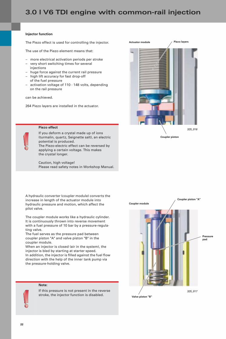
Injector function
The Piezo effect is used for controlling the injector.
The use of the Piezo element means that:
– more electrical activation periods per stroke– very short switching times for several
injections– huge force against the current rail pressure– high lift accuracy for fast drop-off
of the fuel pressure– activation voltage of 110 - 148 volts, depending
on the rail pressure
can be achieved.
264 Piezo layers are installed in the actuator.
3.0 l V6 TDI engine with common-rail injection
A hydraulic converter (coupler module) converts the increase in length of the actuator module into hydraulic pressure and motion, which affect the pilot valve.
The coupler module works like a hydraulic cylinder. It is continuously thrown into reverse movement with a fuel pressure of 10 bar by a pressure-regula-ting valve. The fuel serves as the pressure pad between coupler piston "A" and valve piston "B" in the coupler module.When an injector is closed (air in the system), the injector is bled by starting at starter speed. In addition, the injector is filled against the fuel flow direction with the help of the inner tank pump via the pressure-holding valve.
Note:
If this pressure is not present in the reverse stroke, the injector function is disabled.
Actuator module
Coupler module
325_017
325_016Piezo effect
If you deform a crystal made up of ions (turmalin, quartz, Seignette salt), an electric potential is produced. The Piezo-electric effect can be reversed by applying a certain voltage. This makes the crystal longer.
Caution, high voltage!Please read safety notes in Workshop Manual.
Coupler piston "A"
Valve piston "B"
Piezo layers
Coupler piston
Pressure pad

23
Nozzle closed
Restrictor plate
Inflow with rail pressure
Nozzle spring
Restrictor bore for return
325_028 325_029
ZA
325_018
Pilot valveThe pilot valve consists of a valve plate, valve pin, valve spring and a restrictor plate.
The fuel flows at current rail pressure through the feed restrictor (Z) in the restrictor plate to the nozzle needle and into the space above the nozzle needle. This produces pressure compensation above and below the nozzle needle. The nozzle needle is kept closed mainly by the spring force of the nozzle spring.
When the valve pin is pressed, the return opens and the rail pressure flows off first through a larger drain restrictor (A) above the nozzle needle. The rail pressure lifts the nozzle needle from its seat, thereby causing injection. The fast switching pulses of the Piezo element result in several injections per stroke one after the other.
Coupler element Valve pin
Drain restrictor (A)
Feed restrictor (Z)
Restrictor plate
Nozzle needle Nozzle spring
Coupler element
Valve pin
Pre- and post-injections Two pre-injections are performed when the engineis cold and in the near-idle speed range. As the load increases, the pre-injections are
gradually retarded until only the main injection is used at full power.The two post-injections are needed in order to rege-nerate the particle filter.
Note:
The pre-injections depend on the load, the speed and the engaged gear (acoustics).
High pressure
Low pressure
Nozzle open

24
3.0 l V6 TDI engine with common-rail injection
Oxygen sensorExhaust gas recirculation
Catalytic converter
Temperature sensorG235
Temperature sensorG448
Differential pressure sensorG450
Coated particle filter 325_020
CO – Carbon monoxide
HC – Hydrocarbon
C – Soot
CO2 – Carbon dioxide
NOx – Nitric oxide
H2O – Water
O2 – Oxygen
Particle filter
A particle filter without a catalytic-effect additive is used in the 3.0 l V6 CR diesel engine. The so-called "Catalysed Soot Filter" (CSF) has a filter coatingcontaining precious metal.Several sensors are needed in order to initiate the regeneration of the filter and system monitoring.Three temperature sensors are installed – one in front of the turbocharger, one behind the catalytic converter and one in front of the particle filter. A differential pressure sensor monitors the pressure difference before and after the filter. The accumulation of soot on the filter is detected here.
During passive regeneration without engine mana-gement intervention, the soot stored in the particle filter is converted slowly and carefully into CO2. This happens at temperatures of between 350 °C and 500 °C, primarily when travelling on motorways, due to the low exhaust gas temperature during short journeys or city travel.For frequent city travel, an active regeneration must be performed via engine management every 1,000 - 1,200 km.

25
CO
HC
O2
C
CO2
NOx
H2O
Regeneration is performed, as required, using a pre-programmed simulation model in the engine control unit, which determines the filter loading from the user’s driving profile and the value indicated by the differential pressure sensor.For this purpose, the temperature on the turbocharger is regulated to approx 450 °C by performing a post-injection close to the main injection, by increasing the injection quantity, delaying the injection time, disabling exhaust gas recirculation and by choking on the throttle. When a temperature of approx. 350 °C is exceeded behind the catalytic converter, a second post-injec-tion is performed away from the main injection.This post-injection is so late that the fuel only evaporates and no more combustion takes place.
However, this fuel vapour is converted on thecatalytic converter and increases the gas temperature to up to 750 °C. The soot particles can thus be burned. A temperature sensor on the filter adapts the quantity of the remote post-injection in such a way that a temperature of 620 °C is reached in the underbody position, before the filter. The soot particles can thus be burned in a matter of minutes.With an increasingly high mileage(150,000 - 200,000 km), the filter becomes blocked, depending on oil consumption, and must be replaced. The remains of burned oil (oil ashes), which do not burn and accumulate in the filter, are responsible for this.
Temperature sensor
Differential pressure sensor
Pre-purified exhaust gas with soot
Purified exhaust gas without soot
325_021
Pre-purified exhaust gas with soot
Purified exhaust gas without soot
Particle separation
325_022
The platinum coating of the filter element produces nitrogen dioxide NO2, which causes soot oxidation above a temperature of 350 °C (passive regeneration).The ceroxide component of the coating accelerates the fast thermal regeneration with oxygen (O2) above 580 °C (active regeneration).
The filter element is like a conventional catalytic converter, the only difference being that the pipes are closed off alternately in inlet and outlet direction. This means that the soot-laden exhaust gasses must penetrate the gas-permeable silicon carbide walls. The gas therefore flows to the exhaust system outlet, while the soot stays on the ceramic wall. This is coated with a mixture of platinum and ceroxide.
26
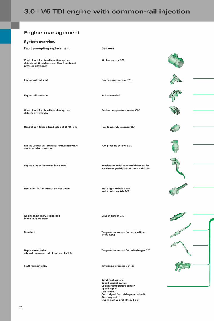
Engine management
System overview
3.0 l V6 TDI engine with common-rail injection
Fuel temperature sensor G81
Air flow sensor G70
Engine speed sensor G28
Fuel pressure sensor G247
Brake light switch F and brake pedal switch F47
Coolant temperature sensor G62
Accelerator pedal sensor with sensor for accelerator pedal position G79 and G185
Additional signals:Speed control systemCoolant temperature sensorSpeed signalTerminal 50Crash signal from airbag control unitStart request to engine control unit (Kessy 1 + 2)
Control unit for diesel injection system detects additional mass air flow from boost pressure and speed
Engine will not start
Fault prompting replacement
Oxygen sensor G39
Sensors
Control unit takes a fixed value of 90 °C - 5 %
Engine control unit switches to nominal value and controlled operation
Reduction in fuel quantity – less power
Control unit for diesel injection system detects a fixed value
Engine runs at increased idle speed
No effect, an entry is recordedin the fault memory
Hall sender G40
Temperature sensor for particle filter G235, G450
Differential pressure sensor
Temperature sensor for turbocharger G20Replacement value – boost pressure control reduced by 5 %
No effect
Fault memory entry
Engine will not start

27
AUTO
ON/OFF
SETUP
AUTO
325_019
Operating and display unit forair-conditioning system J255
Control unit for automatic transmissionJ217
Combination processor in dashboard insert J85
ESP control unit J104
Glow plug control unit J179
Additional signals:
Air-conditioning compressorCoolant preheaterFan stage 1 + 2
Control unit fordiesel direct-injection system J248
Data link connector
Piezo element for injector, cylinder 4 - 6N33 - N83 - N84
Relay for glow plugs J52Glow plugs 1 - 4 Q6
Piezo element for injector, cylinder 1 - 3 N30 - N32
Relay 2 for glow plugs J495Glow plugs 5 - 8 Q6
Throttle control unit N239/J338
Fuel pressure control valve N276
Solenoid valve for exhaust gas recirculation N18
Electric fan
Left/right solenoid valve for electro-hydraulic engine mount N144/N145
Relay for auxiliary heater J359 + J360Auxiliary heater Z35
Fuel pump relay J17Fuel pump (pre-feed pump) G6
Switch-over valve for exhaust gas recirculation cooler N345
Butterfly valve adjuster V157 + V275
Fault entry in control unit
Misfire detection via engine speed sensor,cylinder in question is disabled after several cycles
Remains open
The fuel pressure is regulated by the fuel level regulator in the high-pressure pump. Control unit function changes from regulating to control.
No exhaust gas recirculation possible
Heat control comes on when the engine tempera-ture is exceeded.
Fault memory entry only
No auxiliary heating
Engine starts with filled lines, driving behaviour problems with high fuel throughputs.
By-pass flap is closed, exhaust gas recirculation is always cooled
Butterfly valves remain open
Actuators Fault prompting replacement
Oxygen sensor heater Z19 No oxygen signal, oxygen sensor is switched off and the system is not adjusted

28
Function diagram
3.0 l V6 TDI engine with common-rail injection
M9 Lamp for left brake lightM10 Lamp for right brake light
N18 Exhaust gas recirculation valveN30 Injection valve for cylinder 1N31 Injection valve for cylinder 2N32 Injection valve for cylinder 3N33 Injection valve for cylinder 4N83 Injection valve for cylinder 5N84 Injection valve for cylinder 6N144 Left solenoid valve for electro-hydraulic
engine mountN145 Right solenoid valve for electro-hydraulic
engine mountN276 Fuel pressure control valveN290 Fuel metering valveN335 Intake air switch-over valveN345 Switch-over valve for exhaust gas
recirculation cooler
Q10-15 Glow plugs 1 - 6
S FuseS204 Fuse -1-, terminal 30
V157 Motor for intake pipe flap V275 Motor for intake pipe flap 2
Z35 Heater element for auxiliary air heatingZ19 Oxygen sensor heater
1 Fan stage 1
2 Fan stage 2
3 Engine speed
4 To starter
5 Terminal 50
6 Selector lever (P/N)
7 Terminal 50, stage 1
8 Terminal 50, stage 2
9 CAN BUS L
10 CAN BUS H
11 CAN BUS Convenience
12 CAN BUS Drive
13 To lights
Data link connector
Components
A Battery
E45 Switch for speed control systemE408 Engine start/stop buttonE415 Switch for access and start authorisation
F Brake light switchF47 Brake pedal switch F60 Idle speed switchF194 Clutch pedal switch
(US model only)
G20 Temperature sensor 1 for catalytic converterG23 Fuel pumpG28 Engine speed sensorG31 Boost pressure sensorG39 Oxygen sensorG40 Hall senderG42 Intake air temperature sensorG62 Coolant temperature sensorG70 Air flow sensorG79 Sensor for accelerator pedal positionG81 Fuel temperature sensorG169 Fuel level sensor -2-G185 Sensor -2- for accelerator pedal positionG235 Exhaust gas temperature sensor -1-G247 Fuel pressure sensorG448 Exhaust gas temperature sensor in front of
particle filterG450 Pressure sensor 1 for exhaust gas
J17 Fuel pump relayJ49 Relay for electric fuel pump 2J53 Starter relayJ179 Control unit for glow time mechanismJ248 Control unit for diesel direct-injection systemJ317 Voltage supply relay, terminal 30J329 Power supply relay, terminal 15J338 Throttle control unitJ359 Relay for low heating powerJ360 Relay for high heating powerJ518 Control unit for access and start
authorisationJ694 Power supply relay, terminal 75J695 Starter relayJ724 Control unit for exhaust gas turbocharger
Colour coding
= Input signal
= Output signal
= Bi-directional
= CAN BUS
= Positive
= Ground

29
N30 N32 N33 N31 G79/G185
31
G31 G42
UP
G62G81 G235 G20 G448
J338
M
S
+
G40
P
G247G450
UP
1 2 3 5 6 87
S
G39 Z19
λ
Z35
V275
M
V157
M
J724
M
G70J359 J360
S
J329J694
109
J695 J53
E408
)(10 10 2 3
E415
12
F194N83 N84
+
G28
3015XX
1530
J317
J248
31
S
+
-
A
S
G6
M
J17
J179
Q10 Q11 Q12 Q13 Q14 Q15
N18
S S
N290N345 N276 N144 N145 N335
F/F47
M10
M9
+ -
M
SS
J518
4
13
11
325_040

30
3.2 l V6 FSI engine
Introduction
A V6 engine with FSI technology has been developed for the first time for the new Audi A6.This engine is also used in the A8 and A4.
The following development goals have beenachieved here:
– Compliance with the EU IV exhaust gas standard– Reduced fuel consumption– High performance– High and ample torque– Sporty and agile behaviour with a high level of
comfort– Powerful, sportingly dynamic V6 sound
Technical features are as follows:
– Light-weight crankcase made of an aluminium/silicon/copper alloy
– Light plastic, two-position intake pipe– Balancer shaft for the elimination of first-order
free inertia forces– Low-friction cylinder head with 4-valve roller-type
cam followers– Engine control via rear chain drive– Front ancillary units are driven by Poly-V belts– Continuous camshaft adjustment on inlet and
exhaust side– Siemens engine management with electronic
throttle actuator control (E gas)– Emission control through continuous oxygen
sensing, 2 catalytic converters close to the engine
– P/N system for air mass metering
325_055
31
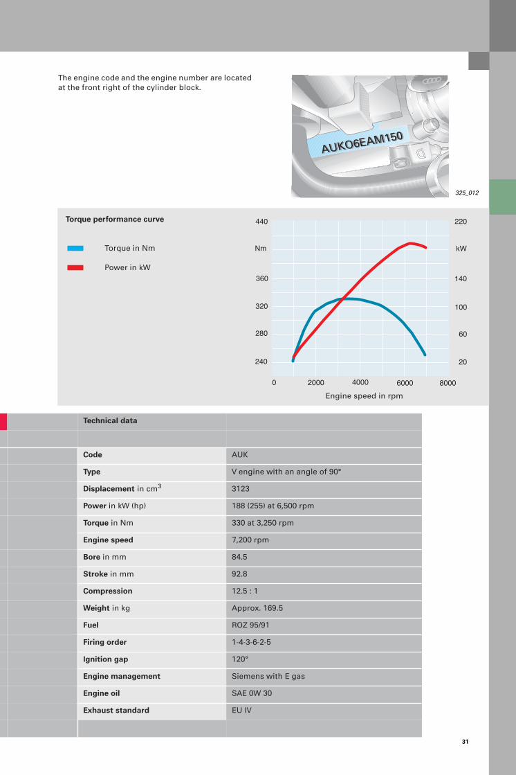
Technical data
Code AUK
Type V engine with an angle of 90°
Displacement in cm3 3123
Power in kW (hp) 188 (255) at 6,500 rpm
Torque in Nm 330 at 3,250 rpm
Engine speed 7,200 rpm
Bore in mm 84.5
Stroke in mm 92.8
Compression 12.5 : 1
Weight in kg Approx. 169.5
Fuel ROZ 95/91
Firing order 1-4-3-6-2-5
Ignition gap 120°
Engine management Siemens with E gas
Engine oil SAE 0W 30
Exhaust standard EU IV
Torque performance curve
Torque in Nm
Power in kW
Engine speed in rpm
Nm
240
100
20
kW
2000 4000
280
320
360
440
140
220
60
6000 80000
AUKO6EAM150AUKO6EAM150
The engine code and the engine number are located at the front right of the cylinder block.
325_012

32
3.2 l V6 FSI engine
Mechanics
Crankcase and crankshaft assembly
The crankcase is made of an aluminium alloy. This over-eutectoid monoblock is manufactured using the chill-casting procedure. No bushings are cast in.
Hard primary silicon particles, which are deposited in the liquefied material, are exposed in a special procedure.
The bottom of the crankcase (bedplate) reinforces the crankcase and contains the four main cranks-haft bearings.
The flood wall (oil plane) and the oil pump are integrated in the top of the oil pan. The bottom of the oil pan contains the oil level sensor.
325_056
Reference
Further information on this can be found in the Self-Study Programme 267.
325_129

33
The crankshaft is a four-position steel crankshaft with a vibration damper. The con-rods are designed as trapezoid industrially-cracked con-rods. The faces are 1 mm wider compared with the 3.0 l V5 engine. The lift pin diameters were increased from 54 mm to 56 mm. This also increased the rigidity as well as the strength of the crankshaft.
The con-rod measurements were reduced (from C70 to 33 Mn VS4) by changing the material used. The higher strength of the new material means that the higher gas forces can be transferred safely.
The forged piston has an FSI-specific combustion chamber well.The piston shaft is coated with a wear-resistant ferrous coating.Piston cooling is performed using oil spray jets.
325_045
325_063
34
3.2 l V6 FSI engine
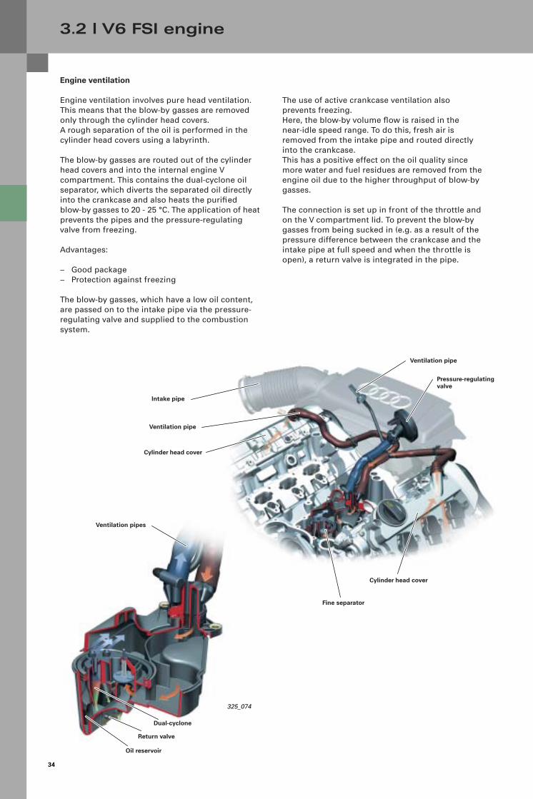
Engine ventilation
Engine ventilation involves pure head ventilation. This means that the blow-by gasses are removed only through the cylinder head covers. A rough separation of the oil is performed in the cylinder head covers using a labyrinth.
The blow-by gasses are routed out of the cylinder head covers and into the internal engine Vcompartment. This contains the dual-cyclone oil separator, which diverts the separated oil directly into the crankcase and also heats the purified blow-by gasses to 20 - 25 °C. The application of heat prevents the pipes and the pressure-regulating valve from freezing.
Advantages:
– Good package– Protection against freezing
The blow-by gasses, which have a low oil content, are passed on to the intake pipe via the pressure-regulating valve and supplied to the combustion system.
The use of active crankcase ventilation also prevents freezing.Here, the blow-by volume flow is raised in the near-idle speed range. To do this, fresh air is removed from the intake pipe and routed directly into the crankcase.This has a positive effect on the oil quality since more water and fuel residues are removed from the engine oil due to the higher throughput of blow-by gasses.
The connection is set up in front of the throttle and on the V compartment lid. To prevent the blow-by gasses from being sucked in (e.g. as a result of the pressure difference between the crankcase and the intake pipe at full speed and when the throttle is open), a return valve is integrated in the pipe.
Intake pipe
Ventilation pipe
Pressure-regulating valve
Cylinder head cover
Fine separator
Cylinder head cover
Ventilation pipes
Dual-cyclone
Return valve
Oil reservoir
Ventilation pipe
325_074
35
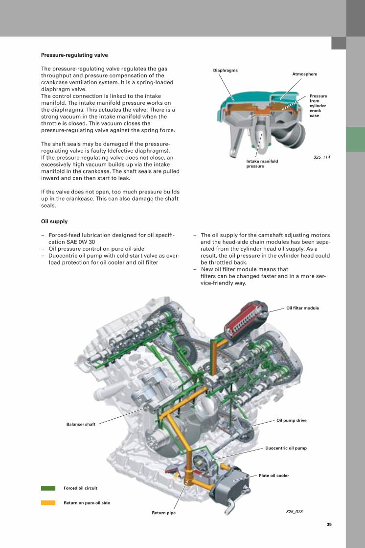
Pressure-regulating valve
The pressure-regulating valve regulates the gas throughput and pressure compensation of the crankcase ventilation system. It is a spring-loaded diaphragm valve. The control connection is linked to the intake manifold. The intake manifold pressure works on the diaphragms. This actuates the valve. There is a strong vacuum in the intake manifold when the throttle is closed. This vacuum closes the pressure-regulating valve against the spring force.
The shaft seals may be damaged if the pressure-regulating valve is faulty (defective diaphragms). If the pressure-regulating valve does not close, an excessively high vacuum builds up via the intake manifold in the crankcase. The shaft seals are pulled inward and can then start to leak.
If the valve does not open, too much pressure builds up in the crankcase. This can also damage the shaft seals.
325_114
Diaphragms
Intake manifold pressure
Pressure fromcylinder crankcase
Atmosphere
Oil supply
– Forced-feed lubrication designed for oil specifi-cation SAE 0W 30
– Oil pressure control on pure oil-side– Duocentric oil pump with cold-start valve as over-
load protection for oil cooler and oil filter
– The oil supply for the camshaft adjusting motors and the head-side chain modules has been sepa-rated from the cylinder head oil supply. As a result, the oil pressure in the cylinder head could be throttled back.
– New oil filter module means that filters can be changed faster and in a more ser-vice-friendly way.
325_073Return pipe
Plate oil cooler
Oil pump drive
Oil filter module
Balancer shaft
Duocentric oil pump
Forced oil circuit
Return on pure-oil side
36
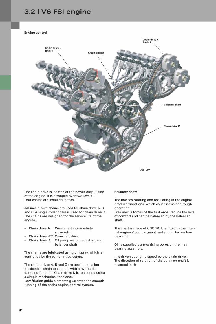
Engine control
3.2 l V6 FSI engine
Chain drive CBank 2
325_057
Chain drive BBank 1
Chain drive A
Chain drive D
The chain drive is located at the power-output side of the engine. It is arranged over two levels. Four chains are installed in total.
3/8-inch sleeve chains are used for chain drive A, B and C. A single roller chain is used for chain drive D.The chains are designed for the service life of the engine.
– Chain drive A: Crankshaft intermediate sprockets
– Chain drive B/C: Camshaft drive– Chain drive D: Oil pump via plug-in shaft and
balancer shaft
The chains are lubricated using oil spray, which is controlled by the camshaft adjusters.
The chain drives A, B and C are tensioned using mechanical chain tensioners with a hydraulic damping function. Chain drive D is tensioned using a simple mechanical tensioner.Low-friction guide elements guarantee the smooth running of the entire engine control system.
Balancer shaft
The masses rotating and oscillating in the engine produce vibrations, which cause noise and rough operation. Free inertia forces of the first order reduce the level of comfort and can be balanced by the balancer shaft.
The shaft is made of GGG 70. It is fitted in the inter-nal engine V compartment and supported on two bearings.
Oil is supplied via two rising bores on the main bearing assembly.
It is driven at engine speed by the chain drive. The direction of rotation of the balancer shaft is reversed in th
Balancer shaft
37
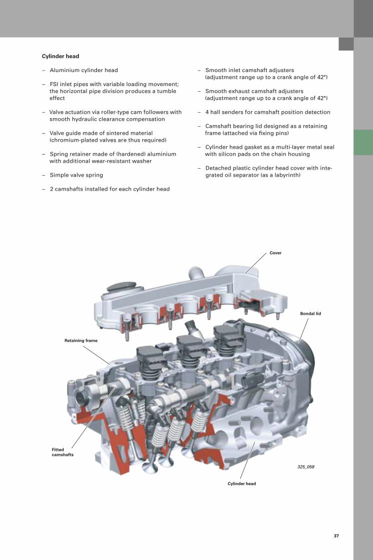
– Smooth inlet camshaft adjusters(adjustment range up to a crank angle of 42°)
– Smooth exhaust camshaft adjusters(adjustment range up to a crank angle of 42°)
– 4 hall senders for camshaft position detection
– Camshaft bearing lid designed as a retaining frame (attached via fixing pins)
– Cylinder head gasket as a multi-layer metal seal with silicon pads on the chain housing
– Detached plastic cylinder head cover with inte-grated oil separator (as a labyrinth)
325_058
Cylinder head
– Aluminium cylinder head
– FSI inlet pipes with variable loading movement; the horizontal pipe division produces a tumble effect
– Valve actuation via roller-type cam followers with smooth hydraulic clearance compensation
– Valve guide made of sintered material (chromium-plated valves are thus required)
– Spring retainer made of (hardened) aluminium with additional wear-resistant washer
– Simple valve spring
– 2 camshafts installed for each cylinder head
Cover
Bondal lid
Cylinder head
Retaining frame
Fitted camshafts
38
3.2 l V6 FSI engine
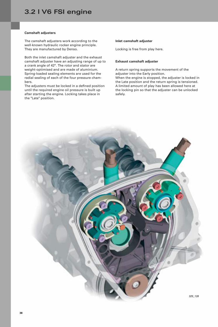
Camshaft adjusters
The camshaft adjusters work according to the well-known hydraulic rocker engine principle. They are manufactured by Denso.
Both the inlet camshaft adjuster and the exhaust camshaft adjuster have an adjusting range of up to a crank angle of 42°. The rotor and stator are weight-optimised and are made of aluminium.Spring-loaded sealing elements are used for the radial sealing of each of the four pressure cham-bers.The adjusters must be locked in a defined position until the required engine oil pressure is built up after starting the engine. Locking takes place in the "Late" position.
Inlet camshaft adjuster
Locking is free from play here.
Exhaust camshaft adjuster
A return spring supports the movement of the adjuster into the Early position. When the engine is stopped, the adjuster is locked in the Late position and the return spring is tensioned. A limited amount of play has been allowed here at the locking pin so that the adjuster can be unlocked safely.
325_128

39
Intake system
The intake system, from the intake opening at the front of the vehicle to the pure air outlet at the filter element, is the same for all engines except for the 2.4 l V6 engine.
A cylindrical air filter cartridge is used to increase the useful life of the air filter.An outlet valve in the filter housing has been used to optimise the discharge of water from the filter housing.
If the engine requires a large amount of air, the engine control unit (active opening) activates the solenoid valve N335 and a vacuum modulator opens the wheel housing inlet.
325_059
The passive opening of the wheel housing inlet is activated if an excessively high vacuum is created in the air filter housing (e.g. obstruction of the intake opening at the front of the vehicle). The increased vacuum forces the flap of the wheel housing inlet open.
The raw-air intake system is fitted with an additional intake pipe from the wheel housing with flow-opti-mised cross-sections.
A snow strainer and hot-air intake system are also available for cold countries. The hot-air intake system is controlled by a wax extension element. The throttle body is a single-flow system andincludes water-heating as an option.
Flexible intake pipe
Air inlet at front of vehicle
Flexible intake pipe
Note:
Engine management is performed without an air flow sensor, i.e. the mass air flow is calculated from the engine speed and intake manifold pressure.

40
3.2 l V6 FSI engine
The switch-over intake pipe is disconnected acoustically in order to reduce noise. It has two settings – short and long intake method – for power and torque.The switching is controlled by a solenoid valve. The pipe is returned to its original setting by spring force. The vacuum accumulator is integrated and has a design function.The duo-sensor (pressure/temperature) as well as the mounting point for the pressure-regulating valve of the ventilation system are located in the intake pipe.
Two selector shafts are used for the longitudinal switching of the switch-over intake pipe. These are connected together via a gear set.
The plastic flaps have an airfoil section, which improves the flow.They have an elastomer extrusion-coating to protect against leakage losses.
325_131
Note:
The engine control unit continuously monitors the position of the intake pipe flaps using hall sensors.
Duo-sensorPressure-regulating valve
Vacuum modulator forswitch-over intake pipe
Position feedback of intake pipe flap
Vacuum modulator forloading switch-over flaps
Electric switch-over valve

41
The intake pipe in the cylinder head is divided horizontally into two halves by an inserted refined-steel plate. It is possible to close off the lower intake pipe using the pre-positioned intake pipe flaps. This increases the flow intensity and causes a rolling movement (tumble) of the air columns in the combustion chamber. The best possible swirling of the fuel-air mixture is achieved in this way.
The intake pipe flaps are fitted eccentrically in order to reduce any flow losses. As a result, they arecompletely integrated into the pipe wall in open position.
The 2-stage adjustment of the intake pipe flaps is achieved via vacuum, while spring force isresponsible for readjustment.In normal position, the flaps are closed as a result of spring force (small cross-section).The position is reported back via hall sensors.
Exhaust system
The exhaust manifold is a cast-iron part. Connections to the cylinder head are divided into individual flanges in order to prevent thermal stress. The exhaust gasses are combined from cylinder 3 to cylinder 2 to cylinder 1, i.e. not a cloverleaf model.
325_062
The oxygen sensor is fitted at the best possible flow point for all three cylinders, thereby allowingcylinder-selective oxygen sensing.Engine management can thus have a greater influ-ence on the fuel/air mix formation of each cylinder.
325_061
325_127

42
Fuel supply
System overview
3.2 l V6 FSI engine
To engine control unit
Quantity control valve N290
High pressure
No pressure
325_041
Injection nozzles 1 - 3
The fuel supply system is divided into two systems, namely the low-pressure and the high-pressure system.
The low-pressure system is a requirement-regulated fuel system. Here, the power of the electric fuel pump (EFP) is regulated by performance electronics via PWM signal (pulse width-modulated). Signal transfer from the engine control unit to the performance electronics also takes place via the PWM signal. There is no fuel return line. The low-pressure sensor N410 ensures that the variable pressure is maintained.
Advantages
– Energy saving due to the lower power consumption of the electric fuel pump
– Lower heat absorption in the fuel – only the fuel quantity that is currently required is compressed
– The service life of the electric fuel pump is exten-ded
– Reduced noise, particularly at idle speed– On-board diagnosis of the low-pressure system
and the shock absorber of the high-pressure system is possible (via the low-pressure sensor)
The pre-feed pressure must be increased by 2 bar for the following operating states:
– When stopping the engine (electric fuel pump after-run)
– Before starting the engine (fuel pump fore-run)when the ignition is on or when the driver’s door contact is up
– While starting the engine and up to around 5 seconds after engine start
– When warm-starting and when the engine is warm – the time depends on the temperature (t < 5 seconds) in order to prevent the formation of vapour bubbles
Fuel filter
High-pressure sensorG247
Note:
When the pump control unit or the engine control unit is replaced, the pump control unit must always be adapted accordingly using the specified troubleshooting steps.
Low-pressure sensorG410
Pressure relief valve
Injection nozzles 4 - 6
Battery Ground Power electronics

43
Single-piston high-pressure pump
This is manufactured by Hitachi.It is driven at the end of the inlet camshaft of bank 2 via a triple cam.It produces a fuel pressure of between 30 and 120 bar. The pressure is set by the quantity control valve N290, depending on the nominal value. The fuel pressure sensor G247 monitors the pressure here.
The pump does not have a leakage line, but feeds the controlled fuel back into the flow-side internally. The low-pressure fuel sensor G410 is integrated in the pump.
This system is a requirement-regulated high-pres-sure pump.This means that only the quantity of fuel stored in the engine control unit map is fed into the high-pressure rail.
The advantage of this system compared with a continuous-feed high-pressure pump is the reduced drive power. Only the fuel that is actually needed is fed into the system.
High-pressure system
The high-pressure system is made up of the following components:
– High-pressure fuel distributor panel, integrated in the intake manifold flange, with pressure sen-sor and pressure-control valve
– High-pressure fuel injection pump– High-pressure fuel lines– High-pressure injection valves
325_060
325_124
Quantity control valve N290
Low-pressure sensorG410

44
3.2 l V6 FSI engine
Intake stroke
The shape of the cam and the force of the piston springs move the pump piston downwards. The increased space in the inside of the pump causes the fuel to flow in. The quantity control valve ensures that the low-pressure valve remains open.The quantity control valve is de-energised.
Useful stroke
The cam moves the pump piston upwards. Pressure still cannot be built up because the quantity control valve is de-energised. This prevents the low-pressure inlet valve from closing.
Pressure stroke
The engine control unit now supplies current to the quantity control valve. The magneto armature is drawn up. The pressure inside the pump presses the low-pressure inlet valve into its seat. If the pressure inside the pump exceeds the rail pressure, the return valve is pushed open and fuel is delivered to the rail.
325_120
325_119
325_118
Low-pressure inlet valve
High-pressure connection to rail
High-pressure valveFuel feed from tank
Quantity control valve N290

45
Like the high-pressure pump, the high-pressure injection valves are also manufactured by Hitachi.Their job is to inject fuel directly into the combu-stion chamber at the right time and in the right quantity.
The engine control unit activates the injection valves by applying approx. 65 volts of power.The quantity of fuel is determined by the opening time and the fuel pressure.The combustion chamber is sealed with a Teflon seal, which must always be replaced following disassembly.
Note:
Replace the Teflon seal using the special tool T10133.
325_042
FSI operating methods
The FSI combustion procedure is essentially restric-ted to homogeneous operation.
The "layer loading operation" method is not imple-mented for the following reason.
In the lower engine speed range and with a low engine load, a high-volume 6-cylinder engine has a lower thermal load than a 4-cylinder engine with low piston displacement. Due to the low exhaust gas temperature, the NOx storage catalytic converter does not reach its operating temperature of up to 600 °C.
The "homogeneous operation" method is divided into two operating states.
1. Homogeneous operation with closed intake manifold flap
The intake manifold flap is closed in the engine speed range up to approx. 3,750 rpm or with an engine load of up to 40 %, depending on the map.The lower intake pipe is closed off. The mass air flow, which is sucked in, is accelerated via the top intake pipe and flows in rolls (tumbles) into the combustion chamber. Injection takes place in the intake tract.
2. Homogeneous operation with open intake manifold flap
The intake manifold flap opens at an engine speed of approx. 3,750 rpm or with an engine load of more than 40 %. This ensures high air throughput at a high engine speed and engine load. This is supported by a high volume-dimensioned two-stage intake pipe, which has switched to suit the performance range (short intake pipe).Injection also takes place in the intake tract here.
Nozzle needle
Armature clearanceof 4/100 mm
Fine strainer
Magnetic coil
Magneto armature
Teflon seal

46
3.2 l V6 FSI engine
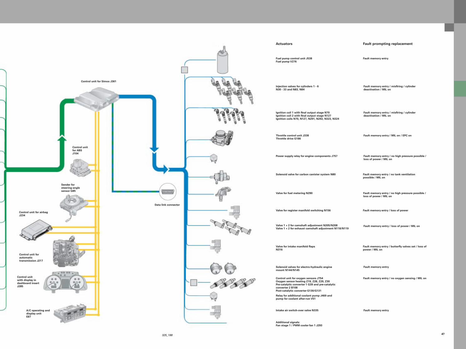
Engine management
System overview
Brake light switch FBrake pedal switch for GRA F47
Manifold pressure sensor G71Intake air temperature sensor G42
Engine speed sensor G28
Fuel pressure sensor G247
Low-pressure fuel sensor G410
Valve for intake manifold flap N316
Throttle control unit J338Angle sensor G188/G187
Hall sender G40Hall sender G163 + G300Hall sender G301
Coolant temperature sensor G62
Potentiometer for intake manifold flap 1 G336Potentiometer for intake manifold flap 2 G512
Sensor for switch-over intake pipe position G513
Sensors
Fault memory entry / MIL on / EPC on
Fault memory entry / compensating engine speed from camshaft speed / MIL on
Fault memory entry / no high pressure possible / loss of power / MIL onFault memory entry / no low-pressure regulation
Fault memory entry / intake manifold flaps scre-wed down / loss of power / MIL on
Fault memory entry / replacement model / loss of power
Fault memory entry / loss of power
Fault memory entry / no oxygen sensing / MIL on
Fault memory entry / replacement model / loss of power
Fault memory entry / intake manifold flaps set / loss of power / MIL on
Fault prompting replacement
Sensor for accelerator pedal position G79Sensor 2 for accelerator pedal position G185Hand switch F36 + F194 only
Knock sensor G61, G66
Additional signals: J393 (door contact signal), J518 (start request), J695 (output from start relay, terminal 50 stage 2), J53 (output from start relay, terminal 50 stage 1), J518 (terminal 50 on starter), J364 (auxiliary heating), E45 (speed control system)
Oxygen sensor ahead of catalytic converter G108 + G39Oxygen sensor behind catalytic converter G130 + G131
Fault memory entry / replacement model / MIL on
Fault memory entry / no camshaft adjustment / loss of power / MIL on
Fault memory entry / MIL on / EPC on
Fault memory entry in transmission control unit
47325_188
Control unit for Simos J361
Control unit for automatic transmission J217
Control unit with display in dashboard insert J285
Sender for steering-angle sensor G85
Data link connector
Control unitfor ABSJ104
A/C operating and display unitE87
Injection valves for cylinders 1 - 6N30 - 33 and N83, N84
Fuel pump control unit J538Fuel pump V276
Ignition coil 1 with final output stage N70Ignition coil 2 with final output stage N127Ignition coils N70, N127, N291, N292, N323, N324
Throttle control unit J338Throttle drive G186
Power supply relay for engine components J757
Solenoid valve for carbon canister system N80
Solenoid valves for electro-hydraulic engine mount N144/N145
Valve 1 + 2 for camshaft adjustment N205/N208Valve 1 + 2 for exhaust camshaft adjustment N118/N119
Additional signals:Fan stage 1 / PWM cooler fan 1 J293
Valve for fuel metering N290
Valve for intake manifold flapsN316
Fault memory entry / misfiring / cylinder deactivation / MIL on
Fault memory entry
Fault memory entry / MIL on / EPC on
Fault memory entry / no high pressure possible / loss of power / MIL on
Fault memory entry / no tank ventilation possible / MIL on
Fault memory entry / loss of power / MIL on
Fault memory entry
Fault memory entry
Fault memory entry / no high pressure possible / loss of power / MIL on
Fault memory entry / butterfly valves set / loss of power / MIL on
Actuators Fault prompting replacement
Fault memory entry / no oxygen sensing / MIL onControl unit for oxygen sensors J754Oxygen sensor heating Z19, Z28, Z29, Z30Pre-catalytic converter 1 G39 and pre-catalytic converter 2 B108Post-catalytic converter G130/G131
Intake air switch-over valve N335
Relay for additional coolant pump J469 and pump for coolant after-run V51
Valve for register manifold switching N156 Fault memory entry / loss of power
Fault memory entry / misfiring / cylinder deactivation / MIL on
Control unit for airbagJ234
48
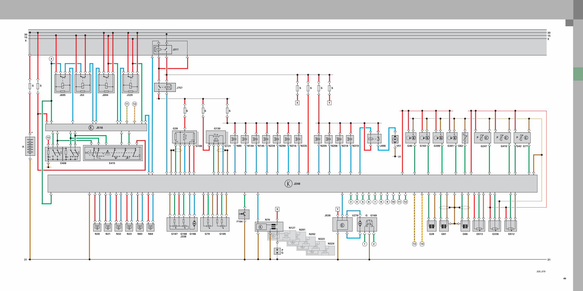
3.2 l V6 FSI engine
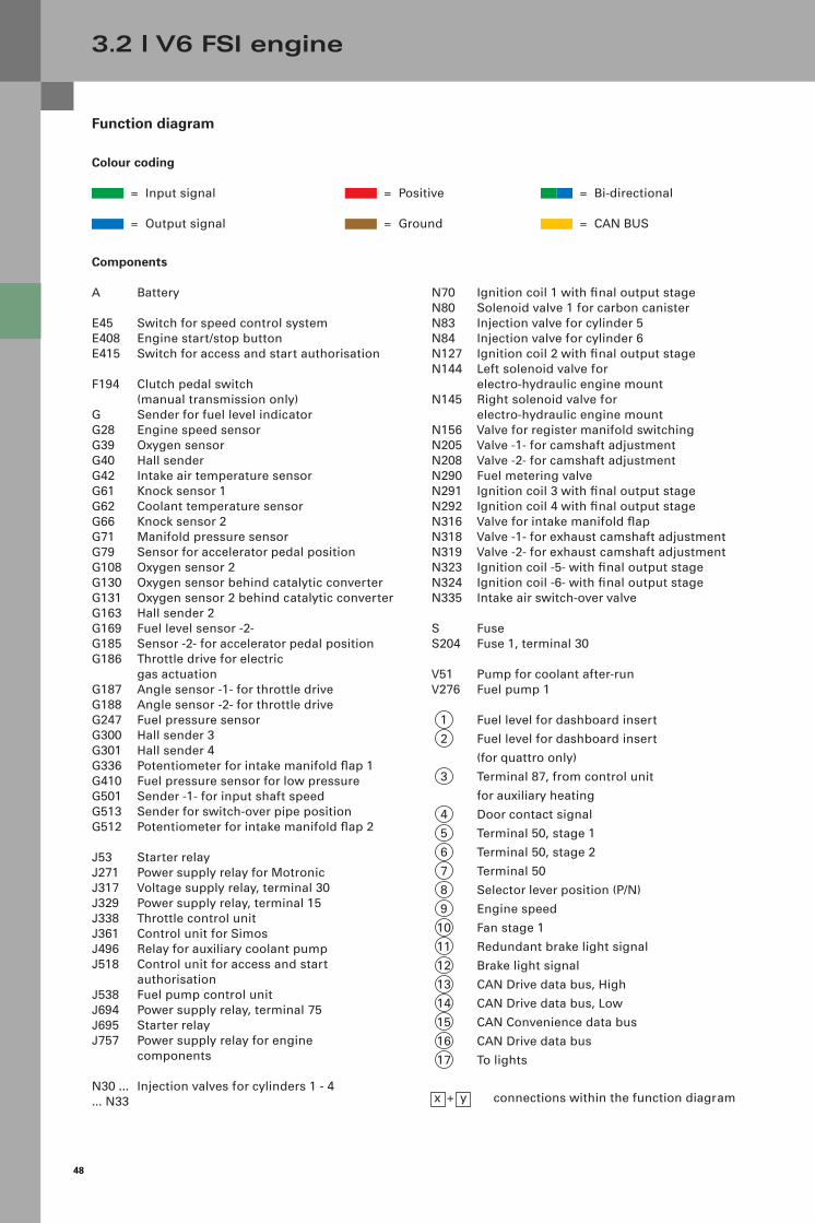
Function diagram
Components
A Battery
E45 Switch for speed control systemE408 Engine start/stop buttonE415 Switch for access and start authorisation
F194 Clutch pedal switch (manual transmission only)
G Sender for fuel level indicatorG28 Engine speed sensorG39 Oxygen sensorG40 Hall senderG42 Intake air temperature sensorG61 Knock sensor 1G62 Coolant temperature sensorG66 Knock sensor 2G71 Manifold pressure sensorG79 Sensor for accelerator pedal positionG108 Oxygen sensor 2G130 Oxygen sensor behind catalytic converterG131 Oxygen sensor 2 behind catalytic converterG163 Hall sender 2G169 Fuel level sensor -2-G185 Sensor -2- for accelerator pedal positionG186 Throttle drive for electric
gas actuationG187 Angle sensor -1- for throttle driveG188 Angle sensor -2- for throttle driveG247 Fuel pressure sensorG300 Hall sender 3G301 Hall sender 4G336 Potentiometer for intake manifold flap 1G410 Fuel pressure sensor for low pressureG501 Sender -1- for input shaft speedG513 Sender for switch-over pipe positionG512 Potentiometer for intake manifold flap 2
J53 Starter relayJ271 Power supply relay for MotronicJ317 Voltage supply relay, terminal 30J329 Power supply relay, terminal 15J338 Throttle control unitJ361 Control unit for SimosJ496 Relay for auxiliary coolant pumpJ518 Control unit for access and start
authorisationJ538 Fuel pump control unitJ694 Power supply relay, terminal 75J695 Starter relayJ757 Power supply relay for engine
components
N30 ... Injection valves for cylinders 1 - 4... N33
Colour coding
= Input signal
= Output signal
= Bi-directional
= CAN BUS
= Positive
= Ground
N70 Ignition coil 1 with final output stageN80 Solenoid valve 1 for carbon canisterN83 Injection valve for cylinder 5N84 Injection valve for cylinder 6N127 Ignition coil 2 with final output stageN144 Left solenoid valve for
electro-hydraulic engine mountN145 Right solenoid valve for
electro-hydraulic engine mountN156 Valve for register manifold switchingN205 Valve -1- for camshaft adjustmentN208 Valve -2- for camshaft adjustmentN290 Fuel metering valveN291 Ignition coil 3 with final output stageN292 Ignition coil 4 with final output stageN316 Valve for intake manifold flapN318 Valve -1- for exhaust camshaft adjustmentN319 Valve -2- for exhaust camshaft adjustmentN323 Ignition coil -5- with final output stageN324 Ignition coil -6- with final output stageN335 Intake air switch-over valve
S FuseS204 Fuse 1, terminal 30
V51 Pump for coolant after-runV276 Fuel pump 1
1 Fuel level for dashboard insert
2 Fuel level for dashboard insert
(for quattro only)
3 Terminal 87, from control unit
for auxiliary heating
4 Door contact signal
5 Terminal 50, stage 1
6 Terminal 50, stage 2
7 Terminal 50
8 Selector lever position (P/N)
9 Engine speed
10 Fan stage 1
11 Redundant brake light signal
12 Brake light signal
13 CAN Drive data bus, High
14 CAN Drive data bus, Low
15 CAN Convenience data bus
16 CAN Drive data bus
17 To lights
x + y connections within the function diagram
49
31
G42 G71G410G247V51
31
N319N318N208N205
S SS
N335N316N290N239N145N144N80
M
G131
N2P2
G108
G130
J317
J757
YX
S
J496
G39
N32 N33 N83 N84N30 N31
F194
G513G66G61G28
13 14
J329J694J695 J53
E408
)(10 10 2 3
E415
12
G187 G188J338
G186
M
G79 G185
43 5 6 7 8 9 10 11 12
M
V276 G G169J538
Y
N127
X
QP
N70
1 2
N291
N292
N323
N324
3015X
J248
31
G512G336
P P
G62
P
SS
λ
S
X1530
+
G301
+
G300
+
G163
+
G40
S
+
-
A
S
J518
4
13
11
325_075

50
Service
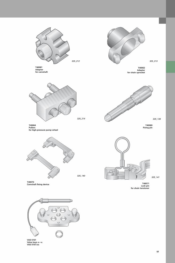
Special tools
3.2 l V6 FSI engine
Universal mounting point
Engine and gearbox holderVAS 6095
Engine-specific mounting point
Here you see the new special tools for the 3.0 l V6 TDI and the 3.2 l V6 FSI engine.
325_207
325_209
325_211
325_206
325_208
325_210
T40049Adapter
Crankshaft turns on flywheel side
T40055Socket wrench forhigh-pressure line
T40053Countererfor high-pressure pump wheel
T40048Assembly device forcrankshaft sealing ring
T40058AdapterCrankshaft turns belt pulley T40060
2 alignment pinsfor chain sprocket
51
325_213325_212
325_214
325_140325_141
325_139
T40064Pullersfor high-pressure pump wheel
T40061 Adapterfor camshaft
T40062Adapter
for chain sprocket
VAS 5161Valve keys a + eVAS 5161/xx
T40069Fixing pin
T40071Lock pin
for chain tensioner
T40070Camshaft fixing device

52
100 %
90
80
70
60
50
40
30
20
10
02->1 3->2 4->3 5->4 6->5
Gearbox – manual transmission
Introduction
In addition to the successful multitronics, newly developed 6-gear transmissions will be used exclusively in the Audi A6 ´05.
Manual transmission
Two new generations of 6-gear manual gearboxes, front and quattro versions respectively, now replace the previously used 5-gear and 6-gear transmissi-ons.
In addition to increasing torque capacity, the main emphasis here has been placed on reworking the inner and outer gearshift. Gearshift force, comfort and precision have been significantly improved. The gearboxes are already used in some Audi A4 and Audi S4 models.
The versions 01X (front) and 02X (quattro) are used for torques of up to 330 Nm.
The 01X is designed for the following engines:– 2.0 l R4 TDI PD– 2.4 l V6 MPI– 3.2 l V6 FSI
325_137
325_195
The 02X is designed for the following engines:– 2.4 l V6 MPI3.2 l V6 FSI
01X
02X
325_202
012
01X
Syn
chro
nis
ing
pow
er a
t th
e se
lect
or s
leev
e
Gearshift
Comparison of synchronising power at the selector sleeve
53
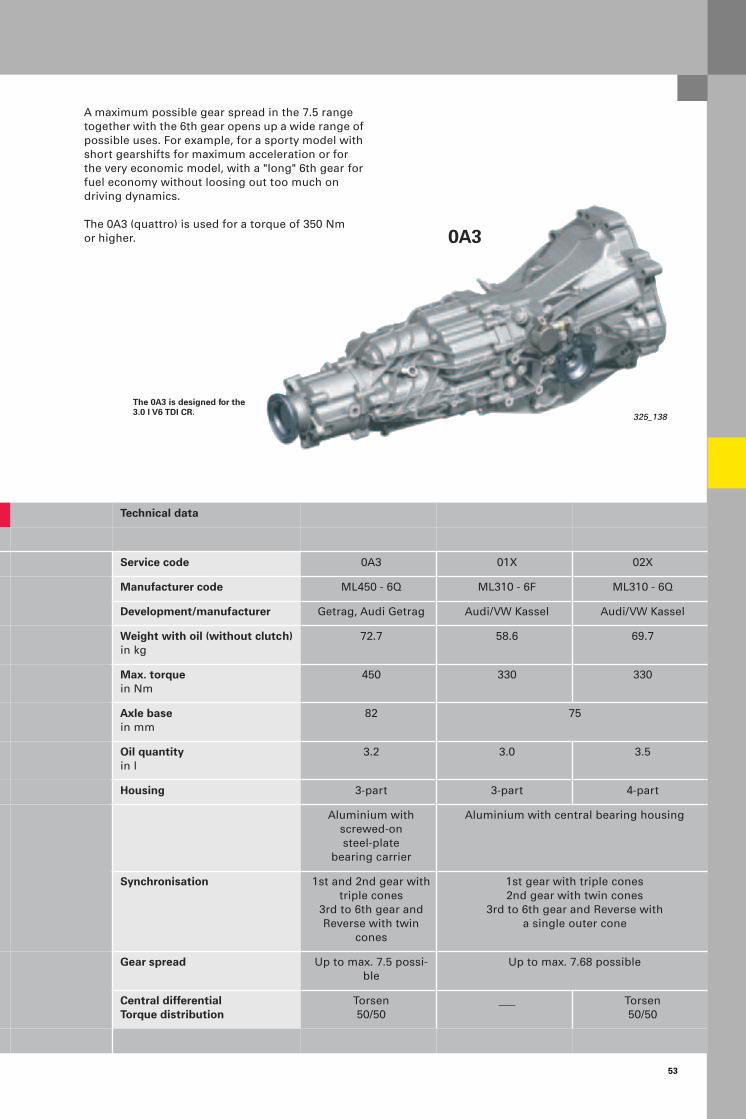
325_138
The 0A3 is designed for the 3.0 l V6 TDI CR.
0A3
Technical data
Service code 0A3 01X 02X
Manufacturer code ML450 - 6Q ML310 - 6F ML310 - 6Q
Development/manufacturer Getrag, Audi Getrag Audi/VW Kassel Audi/VW Kassel
Weight with oil (without clutch) in kg
72.7 58.6 69.7
Max. torque in Nm
450 330 330
Axle base in mm
82 75
Oil quantity in l
3.2 3.0 3.5
Housing 3-part 3-part 4-part
Aluminium with screwed-onsteel-plate
bearing carrier
Aluminium with central bearing housing
Synchronisation 1st and 2nd gear with triple cones
3rd to 6th gear andReverse with twin
cones
1st gear with triple cones2nd gear with twin cones
3rd to 6th gear and Reverse witha single outer cone
Gear spread Up to max. 7.5 possi-ble
Up to max. 7.68 possible
Central differentialTorque distribution
Torsen50/50
___ Torsen50/50
A maximum possible gear spread in the 7.5 range together with the 6th gear opens up a wide range of possible uses. For example, for a sporty model with short gearshifts for maximum acceleration or for the very economic model, with a "long" 6th gear for fuel economy without loosing out too much ondriving dynamics.
The 0A3 (quattro) is used for a torque of 350 Nm or higher.

54
1.2. R.3. 5.6.4.
325_145
Brief description of 0A3 gearbox
Gearbox – manual transmission
Note:
The clutch with SAC pressure plate, which you may already know from the predecessor, is used for power transmission in the 0A3 gearbox (see Self-Study Programme 198).
0A3
Axle base 82 mm
Transmission housing
The gear set is operated in the previously tried-and-trusted way for longitudinal quattro gearboxes using the original quattro hollow shaft.
Four-wheel distribution is achieved using the Torsen differential, which has been used successfully since 1986.
The transmission housing of the 0A3 gearbox is divided into 3 parts and is made completely from pressure-cast aluminium.
The axle base, which was increased from 75 mm (01E) to 82 mm, increases the lever arm, thereby allowing a higher torque transmission.
The new 6-gear manual gearbox 0A3 is a further development of the tried-and-trusted 01E gearbox, which rang in the 6-gear era at Audi at the beginning of the ‘90s.
Like the predecessor gearbox, it was developed jointly by Getrag and Audi and is manufactured by Getrag.
Housing lid
Torsen housing
Torsen differentialHollow shaft
55
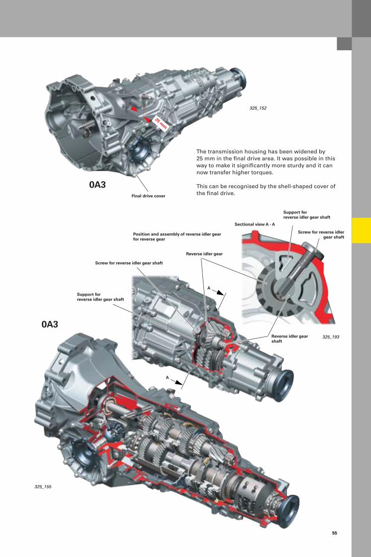
The transmission housing has been widened by 25 mm in the final drive area. It was possible in this way to make it significantly more sturdy and it can now transfer higher torques.
This can be recognised by the shell-shaped cover of the final drive.
325_152
325_193
325_155
Position and assembly of reverse idler gear for reverse gear
25 mm
Sectional view A - A
A
A
0A3
0A3Final drive cover
Support for reverse idler gear shaft
Screw for reverse idlergear shaft
Reverse idler gear shaft
Reverse idler gear
Screw for reverse idler gear shaft
Support for reverse idler gear shaft

56
325_143
325_154
Gearbox – manual transmission
Brief description of the 01X/02X gearbox
The new 6-gear manual gearboxes 01X and 02X replace the previous generation of 5-gear manual gearboxes 012 (01W - 0A9) and 01A.
Like the predecessor gearbox, they were developed by Audi and are manufactured in the VW plant in Kassel.
The transmission housing of the 01X gearbox is divided into 3 parts and is made completely from pressure-cast aluminium.
The axle base, which was increased from 71 mm (012) to 75 mm, increases the lever arm, thereby allowing a higher torque transmission.
Axle base 75 mm
01X
Transmission housing
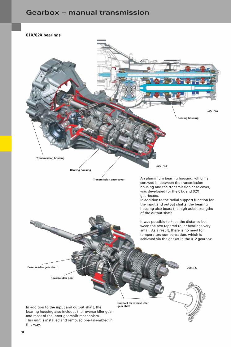
The reverse idler gear for reverse gear is located in the bearing housing.
Bearing housing
Housing lid
Bearing housing
Reverse idler gear
Reverse idler gear shaft
Support for reverse idler gear shaft
1st 2nd Reverse 3rd 4th 6th5th

57
325_187
325_195
25 mm
02X
The gear set is operated in the previously tried-and-trusted way for longitudinal Front gearboxes as a twin-shaft gearbox and for longitudinal quattro gearboxes using the original quattro hollow shaft.
Four-wheel distribution is achieved using the Torsen differential, which has been used successfully since 1986.
Transmission housing
Bearing housing
The transmission housing of the 02X gearbox comprises four aluminium pressure-cast housing sections.
The transmission housing has been widened in the final drive area, as in the 0A3 gearbox, in order to make it more rigid (01X and 02X).
Transmission case cover
Torsen housing
Final drive cover
Transmission housing
Bearing housing
Transmission case cover
Torsen housing
Torsen differentialHollow shaft
325G57_engl.FM Seite 1 Freitag, 13. Februar 2004 7:21 07
58
Gearbox – manual transmission
01X/02X bearings
325_157
325_143
325_154
In addition to the input and output shaft, thebearing housing also includes the reverse idler gear and most of the inner gearshift mechanism. This unit is installed and removed pre-assembled in this way.
An aluminium bearing housing, which is screwed in between the transmissionhousing and the transmission case cover, was developed for the 01X and 02X gearboxes. In addition to the radial support function for the input and output shafts, the bearing housing also bears the high axial strengths of the output shaft.
It was possible to keep the distance bet-ween the two tapered roller bearings very small. As a result, there is no need for temperature compensation, which is achieved via the gasket in the 012 gearbox.
Transmission housing
Bearing housing
Transmission case cover
Reverse idler gear shaft
Reverse idler gear
Support for reverse idler gear shaft
Bearing housing

59
325_155
0A3 bearings
The new feature here is the output shaft bearing application using a double angular contact ball bearing as the fixed bearing.
This has important advantages over the conventio-nal pre-tensioned tapered roller bearing:
– The reduced bearing preload reduces friction, which in turn improves efficiency.
– The fixed/loose bearings (see full section) are not affected by the thermal expansion of the trans-mission housing.
– The double roller bearing, which is used, is a – sealed bearing ("clear bearing"). No dirt (e.g. grit)
can get into the bearing, which extends the service life significantly.
The central shaft is mounted using a screwed bearing carrier made of steel plate. As a result, the housing setup and assembly is simpler.
Output shaft
Double angular contact ball bearing
Bearing carrier
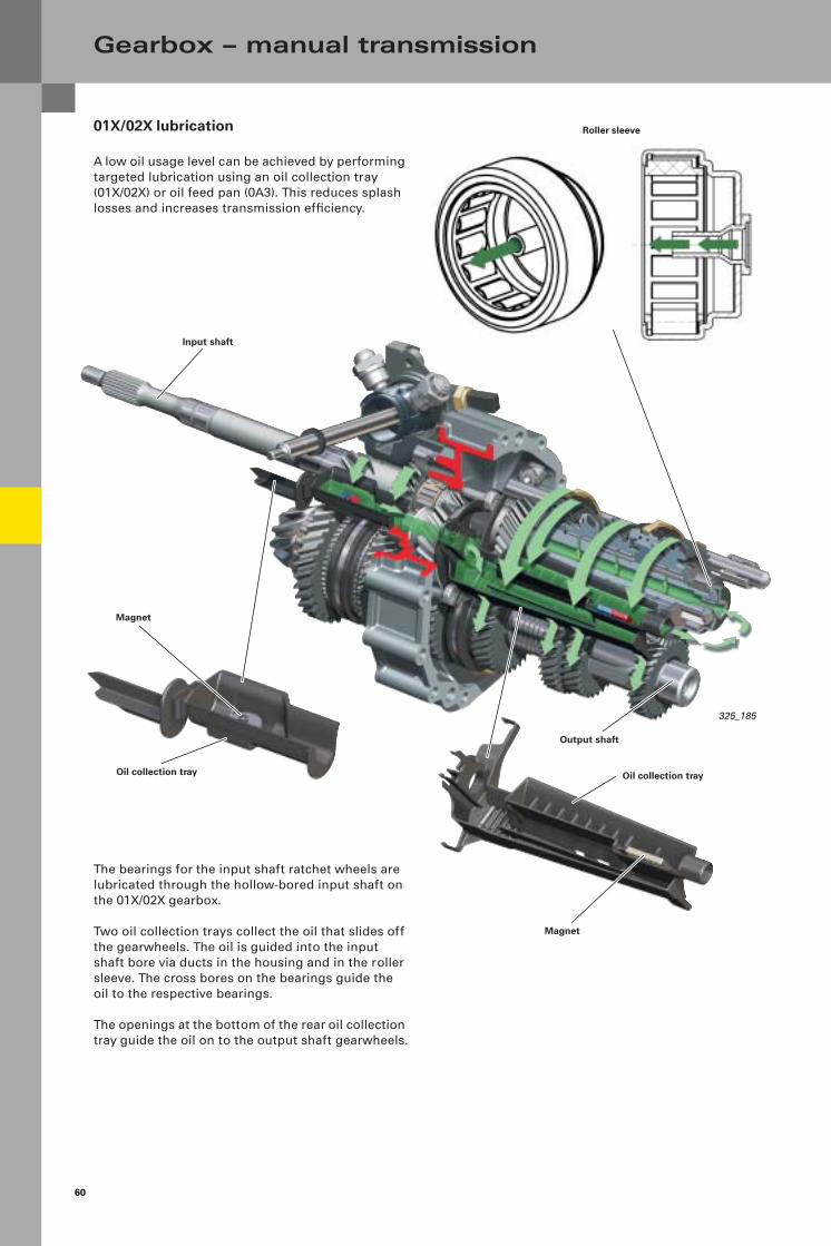
60
Gearbox – manual transmission
01X/02X lubrication
A low oil usage level can be achieved by performing targeted lubrication using an oil collection tray (01X/02X) or oil feed pan (0A3). This reduces splash losses and increases transmission efficiency.
The bearings for the input shaft ratchet wheels are lubricated through the hollow-bored input shaft on the 01X/02X gearbox.
Two oil collection trays collect the oil that slides off the gearwheels. The oil is guided into the input shaft bore via ducts in the housing and in the roller sleeve. The cross bores on the bearings guide the oil to the respective bearings.
The openings at the bottom of the rear oil collection tray guide the oil on to the output shaft gearwheels.
325_185
Magnet
Oil collection tray
Magnet
Input shaft
Output shaft
Roller sleeve
Oil collection tray

61
02X lubrication
The Torsen differential in the 02X gearbox is encapsulated using a so-called sealing cylinder. Lubrication of the Torsen differential is designed in such a way that the grit remains in the Torsendifferential and is not passed into the whole gearbox. The advantage is a longer service life for allbearings.
325_194
325_192
Oil scraper ribs
Oil feed rib
Sealing cylinder
Sealing cylinder
Oil collection tray
Oil supply for the Torsen differential
When the Torsen differential rotates, oil is also passed to the outer wall of the sealing cylinder. Most of this oil is scraped off by the oil scraper rib in the Torsen housing and is passed on to the slightly lower oil scraper rib of the transmission case cover. The oil then flows over the oil feed rib into the sealing cylinder and thus into the Torsen differential.
The bores at the back of the Torsen differential allow the oil to flow back into the Torsen housing , thereby limiting the oil level.
Transmission case cover
Torsen housing
Sectional view of Torsen (fitted)

62
0A3 lubrication
Gearbox – manual transmission
325_156 Oil pump installation position(not necessary at present)
The 0A3 can be fitted with an oil pump for oil cooling, if required.
Oil feed pan
In the 0A3 gearbox, an oil feed pan is used for targeted lubrication and also helps to improve efficiency here.
The success of all the measures aimed at improving efficiency is already apparent in that unlike the predecessor gearbox, no oil cooling (with oil pump) is necessary on the Audi S4 with 0A3 gearbox, for example.
The new 6-gear transmissions are filled with the transmission oil G 052 911 A (SAE 75W 90 synthetic oil), which was used previously.The transmission oil does not need to be changed as part of normal maintenance work – "lifetime fill".
325_155

63
Notes

64
Inner gearshift
Particular attention was paid to gearshift comfort in the new gearboxes. Gearshift force and gearshift times are reduced by reworked, highly-efficient synchronisations.Reverse gear has also been completely synchro-nised.
The gearshift feel has been optimised thanks to numerous individual measures applied to the internalgearshift operation (locks, shift cylinders, shift rods and selector sleeves, bearings and stops).
To improve the shift operation, the shift rods and locks are fitted with ball bearings.
The gates and locking contours of the shift rods and shift cylinder are designed in such a way that they guarantee freedom from play in neutral position and in the selected end position.
Gearbox – manual transmission
325_159
01X
The shift forks of the forward gears are mounted in an oscillating position on the shift rods. This balances out wobbling movements in the selector sleeves and prevents them from reaching the outer gearshift mechanism. As a result, no troublesome vibrations are felt in the gearshift lever.
The shift cylinder has separate gate/locking elements for the shift and selector direction, which produce the selector and return power to neutral position.
Defined contours in the gates support theshift operation in a positive way.
0A3
Shift forks in oscilla-ting position
Bearing housing
Shift rods fitted with ball bearings
Shift rod
Locking sleeve fitted with ball bearings
Selector gate Shift gates
Stop pin
Shift rods fitted with ball bea-rings
325_160

65
Disengaging the inner gearshift mechanism
The shift cylinder has a stop at its end position (gear engaged). The kinematics of the locks is designed in such a way that the shift finger of the shift cylinder does not touch the shift jaws of the shift rails in this position.Vibrations in the shift rods are thusremoved from the selector shaft and are therefore not transferred to the manual shift lever.
In neutral, the locks control the disenga-ging action from the shift finger to the shift jaws.
325_158
325_196
Play
Play
Stop pin Shift jaws
Shift finger
Stop
Stop
Shift gatesShift cylinder
Selector gate
Shift rod
Shift forks in oscillating position
Locking sleeve fitted with ball bearings
Selector shaft
Shift cylinder
Switch for reversing lights F4
Stop pin

66
Gearbox – manual transmission
0A3 synchronisation
1st and 2nd gear are switched using triple-cone synchronisation, i.e. the Borg Warner system. Carbon friction linings are used to achieve a high service life and synchronisation performance.
3rd to 6th gear and reverse gear are switched using twin-cone synchronisation, also based on the Borg Warner system.Synchronising rings with sintered linings are used.
325_105
325_106
Triple-cone synchronisation1st/2nd gear
Twin-cone synchronisation3rd/4th/5th/6th and reverse gear
Ratchet wheel for 3rd gear
Ratchet wheel for 1st gear
Synchronising body for 1st/2nd gear
Selector sleeve for 1st/2nd gear
Ratchet wheel for 2nd gear
Ratchet wheel for 4th gear
Synchronising body for 3rd/4th gear
Selector sleeve for 3rd/4th gear
Shift fork for 1st/2nd gear
Shift fork for 3rd/4th gear
Inner ring
Intermediate ring
Synchronising ring
Pressure piece
Synchronising ring
Intermediate ring
Inner ring
Inner ring
Intermediate ring
Synchronising ring
Pressure piece
Synchronising ring
Intermediate ring
Inner ring
Lock (3rd/4th gear only)

67
01X and 02X synchronisation
1st gear uses triple-cone synchronisation and 2nd gear uses twin-cone synchronisation, i.e. the Borg Warner system with carbon linings, while 3rd to 6th gear and reverse gear use single outer cone synchronisation, i.e. the Audi system made of molybdenum-sprayed brass.
325_190
325_189
Single outer cone synchronisation3rd/4th/5th/6th and reverse gear
Triple-cone synchronisation
Ratchet wheel for 1st gear
Ratchet wheel for 2nd gear
Synchronising body for 1st/2nd gear
Selector sleeve for 1st/2nd gear
Ratchet wheel for 3rd gear
Synchronising body for 3rd/4th gear
Selector sleeve for 3rd/4th gear
Ratchet wheel for 4th gear
Synchronising ring for 3rd gear
Synchronising ring for 4th gear
Twin-cone synchronisation
Shift fork for 3rd/4th gear
Shift fork for 1st/2nd gear
Inner ring
Intermediate ring
Synchronising ring
Synchronising ring
Intermediate ring
Inner ring
Triple Twin
Pressure piece

68
01X/02X/0A3 gear selector(outer gearshift)
The fundamental design of the gear selector (outer gearshift) for the 01X/02X and 0A3 gearboxes is the same.
The shift direction (view Z in illustration) between the gearbox types 01X (02X) and 0A3 is going the opposite way. While the selector shaft is turned to the right to shift into 1st gear in the 01X, for example, it must be turned to the left in the 0A3. Since the gear selector is the same, the transmission shift lever and thus also the linkage is adapted according to the relevant gearbox type.
Gearbox – manual transmission
Connecting rod
Transmission shift lever
View Z (Example: shifting into 1st gear)
Shift rod
Transmission shift lever
01X
Shift rod
01X

69
Smooth gearshift
To keep the load-shift movements of the gearbox as far as possible away from the gearshift lever, the gearshift lever mount is movable.
Function:
The shift rod transfers the load-shift movements of the gearbox to the gearshift lever. The push bar connects the gearbox to the gearshift lever mount and also transfers the gearboxmovements to the gearshift lever mount. The gearshift lever mount is supported on two rails that can be moved along the longitudinal axis of the vehicle and can follow the movements of the gearbox.
The points at which the push bars are secured to the gearbox and ball housing are selected in such a way that the movements caused by the shift rod are balanced out. The gearshift lever thus remains very muchundisturbed in its position during load shifts.
When adjusting the gearshift, the position of the gearshift lever mount must first be adjusted. No special tools are needed (see Workshop Manual).
Push bar
Gearshift lever mount adjustment
Gearshift lever
Gearshift lever mount
Gearshift adjustment Rails
325_142
0A3
Noise cover
Shift rod
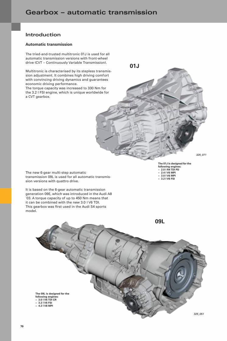
70
Gearbox – automatic transmission
Introduction
Automatic transmission
The tried-and-trusted multitronic 01J is used for all automatic transmission versions with front-wheel drive (CVT – Continuously Variable Transmission).
Multitronic is characterised by its stepless transmis-sion adjustment. It combines high driving comfort with convincing driving dynamics and guarantees economic driving performance. The torque capacity was increased to 330 Nm for the 3.2 l FSI engine, which is unique worldwide fora CVT gearbox.
The new 6-gear multi-step automatic transmission 09L is used for all automatic transmis-sion versions with quattro drive.
It is based on the 6-gear automatic transmission generation 09E, which was introduced in the Audi A8 ´03. A torque capacity of up to 450 Nm means thatit can be combined with the new 3.0 l V6 TDI.This gearbox was first used in the Audi S4 sports model.
325_071
325_051
The 01J is designed for the following engines:– 2.0 l R4 TDI PD– 2.4 l V6 MPI– 3.0 l V6 MPI– 3.2 l V6 FSI
The 09L is designed for the following engines:– 3.0 l V6 TDI CR– 3.2 l V6 FSI– 4.2 l V8 MPI
01J
09L
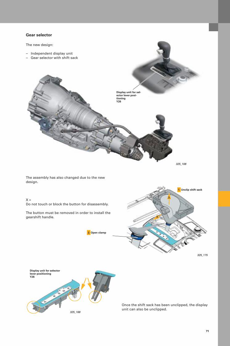
71
Gear selector
The new design:
– Independent display unit– Gear selector with shift sack
2. Open clamp
The assembly has also changed due to the new design.
Once the shift sack has been unclipped, the display unit can also be unclipped.
325_108
325_175
325_168
Display unit for sel-ector lever posi-tioningY26
3.
X
1. Unclip shift sack
Display unit for selector lever positioningY26
X = Do not touch or block the button for disassembly.
The button must be removed in order to install the gearshift handle.
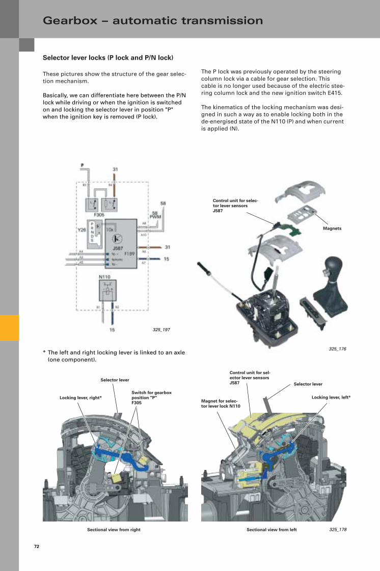
72
Gearbox – automatic transmission
Selector lever locks (P lock and P/N lock)
These pictures show the structure of the gear selec-tion mechanism.
Basically, we can differentiate here between the P/N lock while driving or when the ignition is switched on and locking the selector lever in position "P" when the ignition key is removed (P lock).
Magnet for selec-tor lever lock N110
Control unit for sel-ector lever sensors J587
Locking lever, left*
Sectional view from left 325_178
325_176
Locking lever, right*Switch for gearbox position "P"F305
Sectional view from right
Selector lever
The P lock was previously operated by the steering column lock via a cable for gear selection. This cable is no longer used because of the electric stee-ring column lock and the new ignition switch E415.
The kinematics of the locking mechanism was desi-gned in such a way as to enable locking both in the de-energised state of the N110 (P) and when current is applied (N).
Selector lever
325_197
Magnets
Control unit for selec-tor lever sensors J587
* The left and right locking lever is linked to an axle (one component).

73
325_170
Locking lever
P/N signal from J217
N position
P position
Lock in position "N"
The magnet N110 is activated and presses the lokking lever up, where its hooks engage in the N position and it is locked.To release the lock, the magnet N110 is deactivated and the locking lever drops down.
The magnet N110 is controlled directly by the control unit J217 (see function diagram).
N110
Terminal 15
325_171
N110
Emergency release for P lock
Because the P lock is only released when the magnet N110 is activated, the selector lever remains locked in position "P" in the event of malfunctions (e.g. battery flat, magnet N110 does not function, ...).
The emergency release lever on the left locking lever can be used to move the vehicle in such an instance..
The emergency release can be accessed by remo-ving the ashtray slot and the cover clip beneath.
The locking lever is released by pressing the emergency release lever (e.g. with a pin). The button must be pressed and the selector lever pulled back at the same time.
325_174Emergency release lever
Cover clip Ashtray slot
Note:
The N110 is controlled by negative force in the 09L gearbox.The N110 is controlled by positive force in the 01J gearbox (see the relevant function diagram).
Selector lever in position "P"Selector lever in position "N"
Tappet travel
Lock in position "P"
The magnet N110 is deactivated and the locking lever is locked by gravity and the springs in the N110 magnet.To release the lock, the magnet N110 is activated and the magnet then presses the locking lever out of the P position.
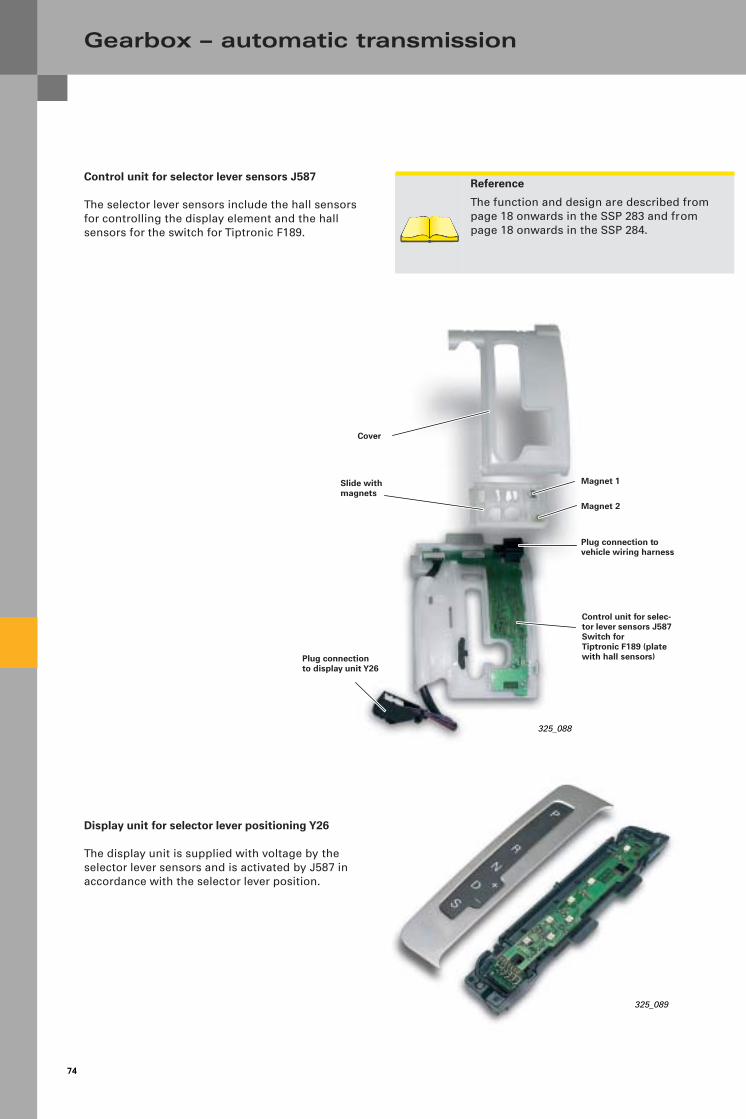
74
Gearbox – automatic transmission
Control unit for selector lever sensors J587
The selector lever sensors include the hall sensors for controlling the display element and the hallsensors for the switch for Tiptronic F189.
Reference
The function and design are described from page 18 onwards in the SSP 283 and from page 18 onwards in the SSP 284.
Plug connection to display unit Y26
Slide with magnets
Cover
Plug connection to vehicle wiring harness
Control unit for selec-tor lever sensors J587Switch for Tiptronic F189 (plate with hall sensors)
325_088
325_089
Magnet 1
Magnet 2
Display unit for selector lever positioning Y26
The display unit is supplied with voltage by the selector lever sensors and is activated by J587 in accordance with the selector lever position.

75
325_177
Switch for gearbox position "P"F305
325_183
Emergency release
Micro switch 2
Ignition key anti-removal lock
The function of the ignition key anti-removal lock is fundamentally changed. Because of the "electronic ignition switch" E415 (switch for access and start authorisation) andthe electromagnetic steering column lock, the mechanical connection (cable) from the gear selector to the steering column lock is no longer used.
The release for the ignition key anti-removal lock is controlled by the switch for access and start authorisation E415 and is operated by the magnet for the ignition key anti-removal lock N376, whichis integrated into the E415.
Reference
The basic function of the ignition key anti-remo-val lock is described from page 28 onwards in the Self-Study Programme 283
Micro switch 1with resistor
The information from selector lever position "P" supplies the two mechanical micro switches F305. They are connected in series and form one unit.
Both switches are closed in selector lever position "P" and supply a ground signal to the E415. If the ignition is switched off, the magnet N376 is supplied with current for a short time and a lever mechanism lifts up the ignition key anti-removal lock.
Two micro switches are installed for safety reasons:
Micro switch 1 is only actuated (hit) when the selec-tor lever button is released in selector lever position "P" (button not pressed). The series-connected resi-stor allows the diagnosis of the signal lead.
Micro switch 2 is only actuated when the locking lever for the P/N lock is in the initial position (see function description for P/N lock).It signals the actual locking in selector lever position "P".
Micro switch 1 Micro switch 2
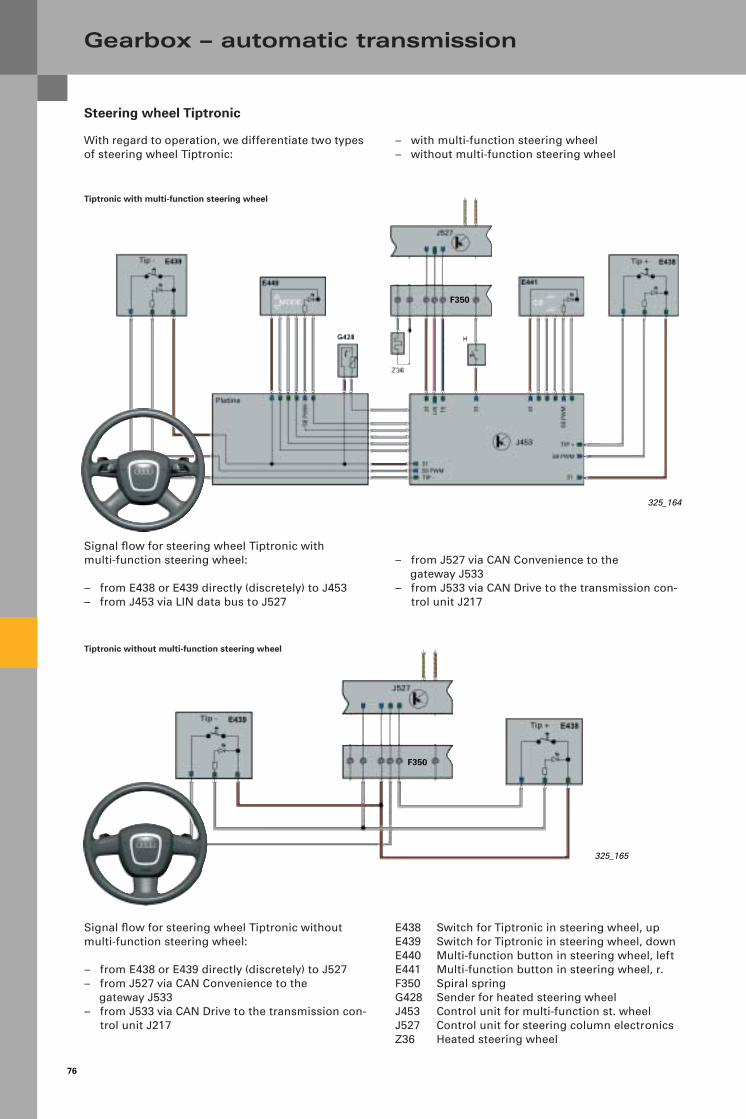
76
Steering wheel Tiptronic
With regard to operation, we differentiate two types of steering wheel Tiptronic:
Gearbox – automatic transmission
325_164
325_165
Tiptronic without multi-function steering wheel
Tiptronic with multi-function steering wheel
– with multi-function steering wheel– without multi-function steering wheel
– from J527 via CAN Convenience to the gateway J533
– from J533 via CAN Drive to the transmission con-trol unit J217
Signal flow for steering wheel Tiptronic with multi-function steering wheel:
– from E438 or E439 directly (discretely) to J453– from J453 via LIN data bus to J527
E438 Switch for Tiptronic in steering wheel, upE439 Switch for Tiptronic in steering wheel, downE440 Multi-function button in steering wheel, leftE441 Multi-function button in steering wheel, r.F350 Spiral springG428 Sender for heated steering wheelJ453 Control unit for multi-function st. wheelJ527 Control unit for steering column electronicsZ36 Heated steering wheel
Signal flow for steering wheel Tiptronic without multi-function steering wheel:
– from E438 or E439 directly (discretely) to J527– from J527 via CAN Convenience to the
gateway J533– from J533 via CAN Drive to the transmission con-
trol unit J217
F350
F350
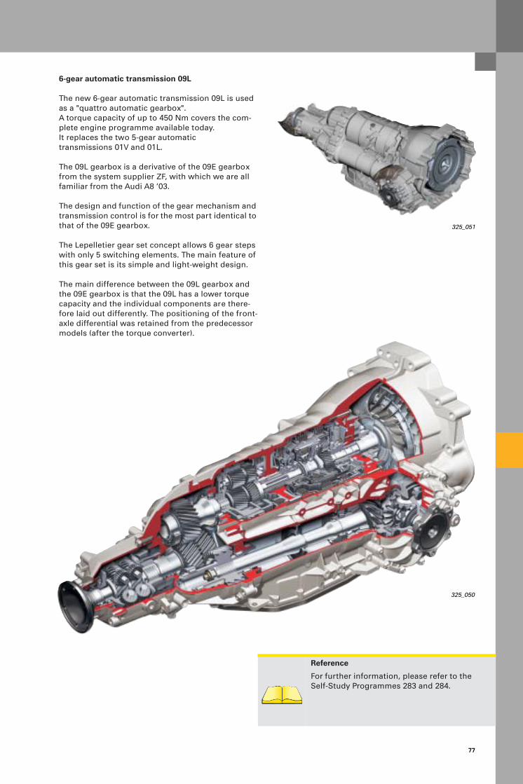
77
325_051
325_050
Reference
For further information, please refer to the Self-Study Programmes 283 and 284.
6-gear automatic transmission 09L
The new 6-gear automatic transmission 09L is used as a "quattro automatic gearbox".A torque capacity of up to 450 Nm covers the com-plete engine programme available today. It replaces the two 5-gear automatic transmissions 01V and 01L.
The 09L gearbox is a derivative of the 09E gearbox from the system supplier ZF, with which we are all familiar from the Audi A8 ‘03.
The design and function of the gear mechanism and transmission control is for the most part identical to that of the 09E gearbox.
The Lepelletier gear set concept allows 6 gear steps with only 5 switching elements. The main feature of this gear set is its simple and light-weight design.
The main difference between the 09L gearbox and the 09E gearbox is that the 09L has a lower torque capacity and the individual components are there-fore laid out differently. The positioning of the front-axle differential was retained from the predecessor models (after the torque converter).
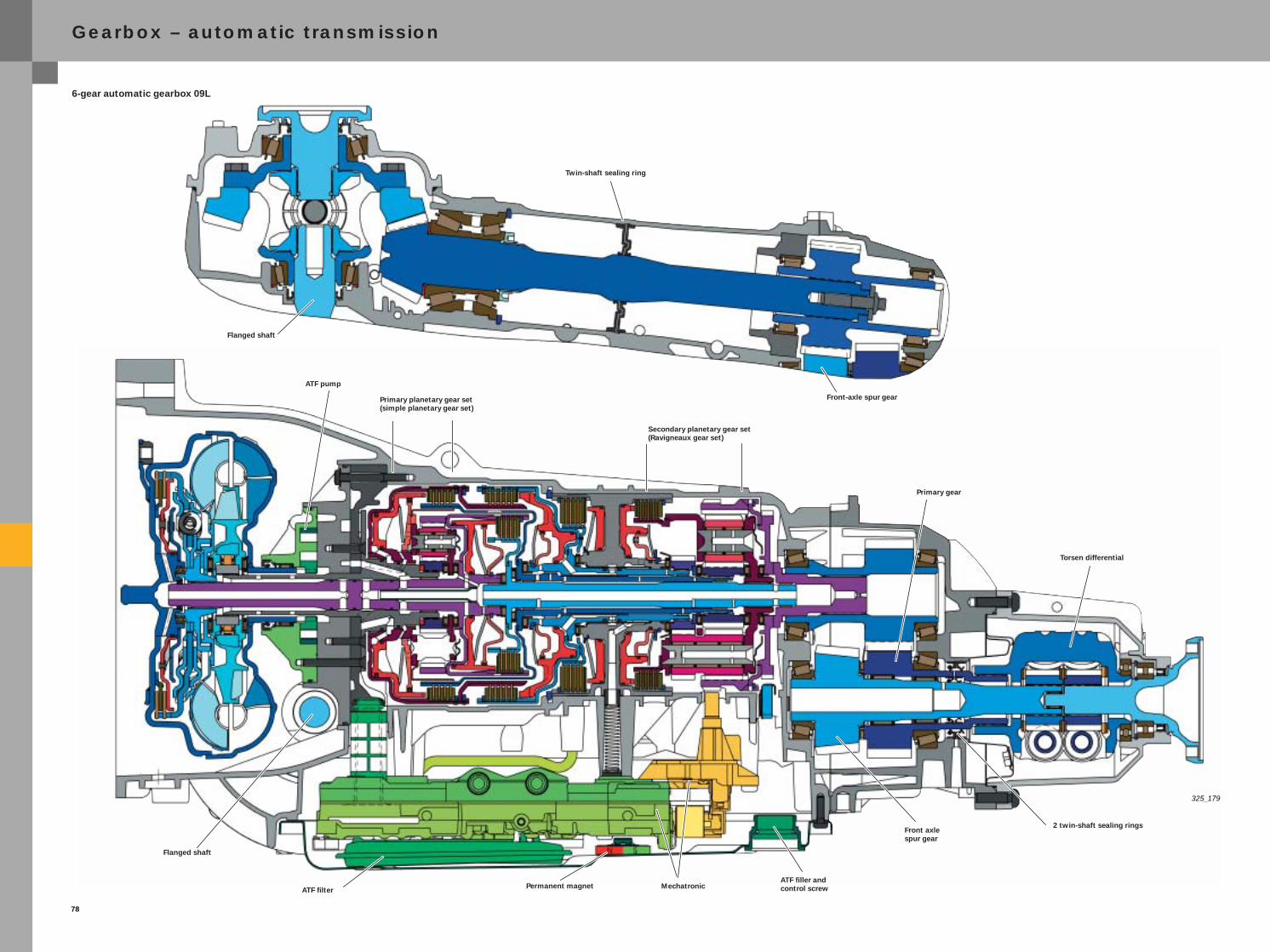
78
325_179
Gearbox – automatic transmission
ATF pump
Primary planetary gear set(simple planetary gear set)
6-gear automatic gearbox 09L
Flanged shaft
ATF filterATF filler and control screwMechatronicPermanent magnet
Secondary planetary gear set(Ravigneaux gear set)
Primary gear
Torsen differential
Front axlespur gear
2 twin-shaft sealing rings
Twin-shaft sealing ring
Front-axle spur gear
Flanged shaft
325G78_engl.FM Seite 1 Freitag, 13. Februar 2004 7:29 07
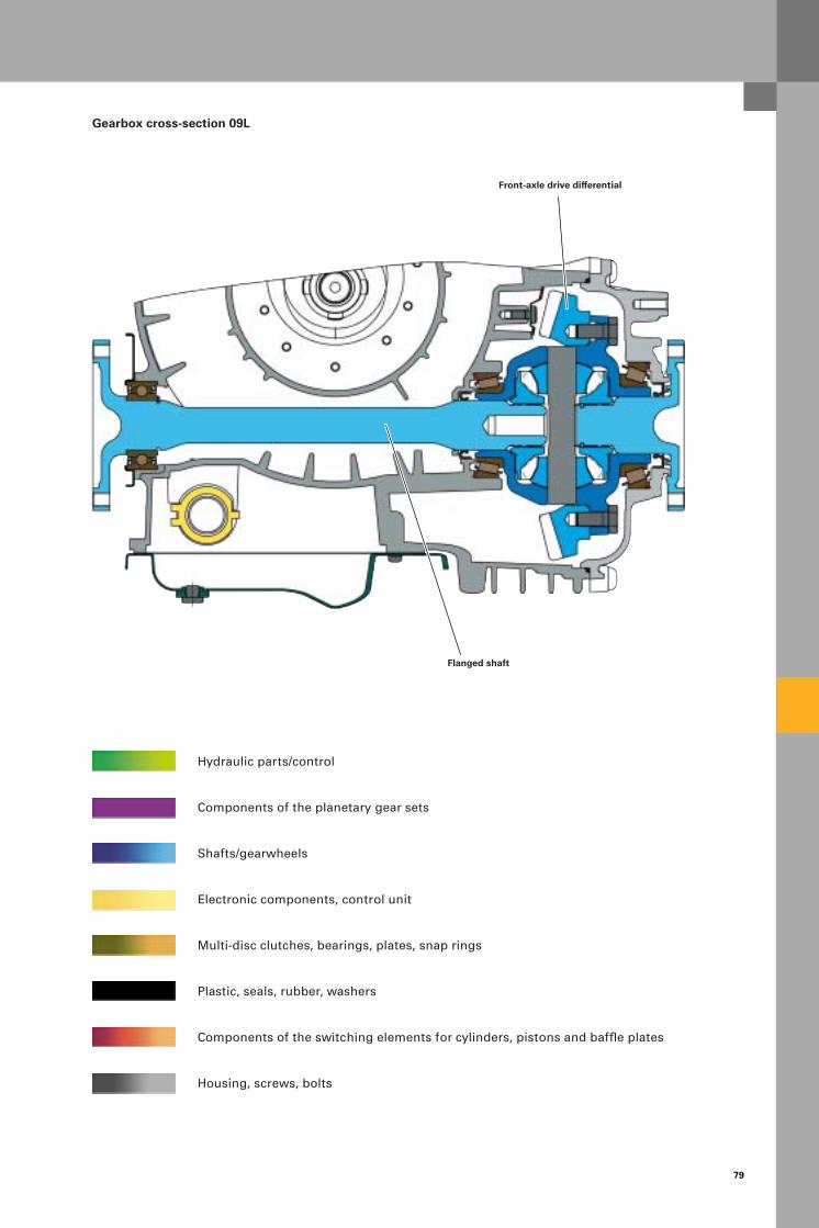
79
Gearbox cross-section 09L
Hydraulic parts/control
Components of the planetary gear sets
Shafts/gearwheels
Electronic components, control unit
Multi-disc clutches, bearings, plates, snap rings
Plastic, seals, rubber, washers
Components of the switching elements for cylinders, pistons and baffle plates
Housing, screws, bolts
Front-axle drive differential
Flanged shaft

80
Gearbox – automatic transmission
Apart from the additional gear ratios and the high torque capacity, the following improvements have been made to the 09L gearbox:
– It weighs 14 kg less(compared to the 01V)
– Improved efficiency
– Increased kingpin inclination
– Further developed DSP
– Higher shift speeds
– Improved shift quality
Technical data
Service code 09L
ZF code 6HP-19A
Audi code AL 420 6Q
Gearbox type 6-gear planetary transmission (multi-step automatic trans-mission),
electronically controlled with hydro-dynamic torque converter with
slip-controlled torque converter lockup clutch
Control Mechatronic (integration of the hydraulic control unit and electric control to form one unit)
Dynamic switching programme with a separate sport programme "S" and the Tiptronic switching pro-
gramme for manual gear change
Torque converter W255 RH-4 GWK
Power transmission Permanent four-wheel drive "quattro" with Torsen central differential
ATF 9.0 litre G 055 005 (Shell ATF M-1375.4)Lifetime fill
Differential, FA/RA 1.1 litre/0.5 litreG 052 145 (Burmah SAF-AG4 1016)
Lifetime fill
Weight including oil in kg Approx. 115 kg
Max. torque in Nm Up to 450 Nm, depending on engine version
Kingpin inclination 6.04
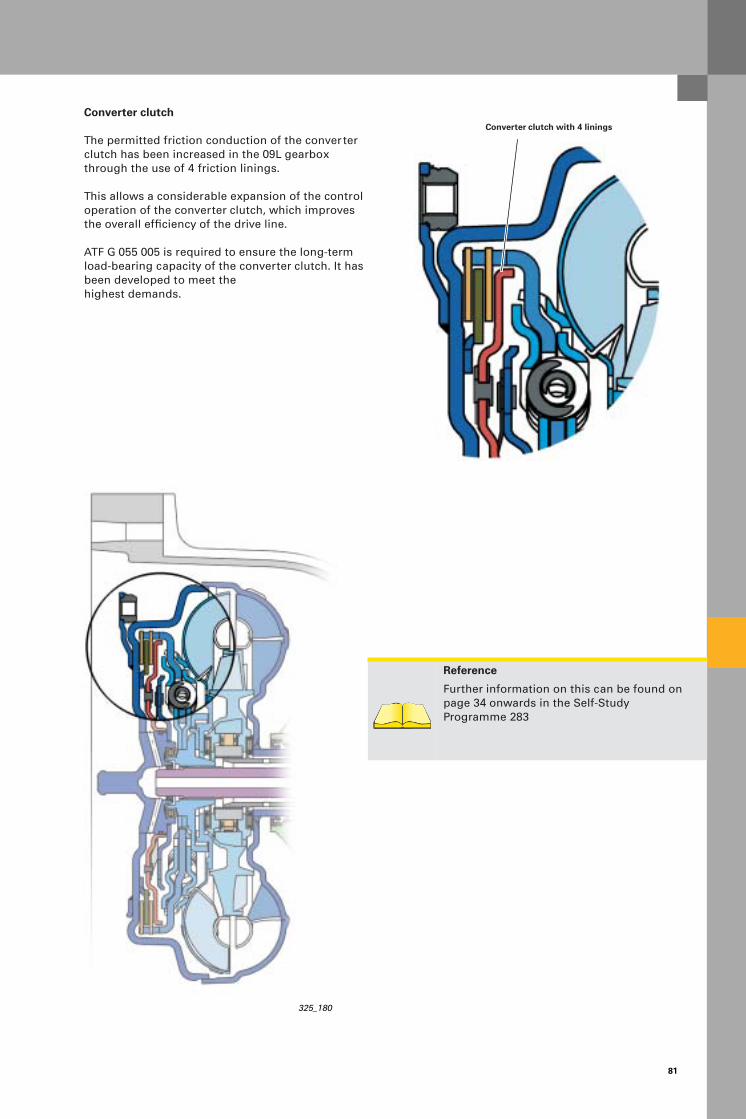
81
Converter clutch
The permitted friction conduction of the converter clutch has been increased in the 09L gearbox through the use of 4 friction linings.
This allows a considerable expansion of the control operation of the converter clutch, which improves the overall efficiency of the drive line.
ATF G 055 005 is required to ensure the long-term load-bearing capacity of the converter clutch. It has been developed to meet the highest demands.
325_180
Reference
Further information on this can be found on page 34 onwards in the Self-Study Programme 283
Converter clutch with 4 linings
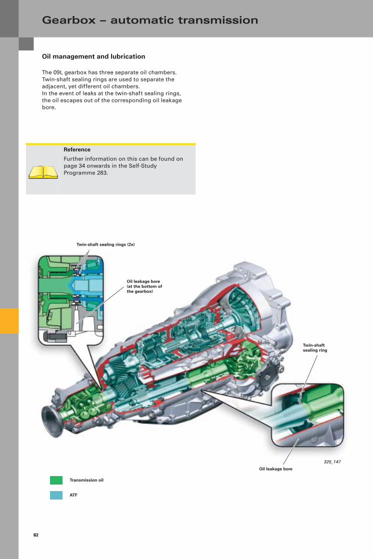
82
Gearbox – automatic transmission
Oil management and lubrication
The 09L gearbox has three separate oil chambers. Twin-shaft sealing rings are used to separate the adjacent, yet different oil chambers. In the event of leaks at the twin-shaft sealing rings, the oil escapes out of the corresponding oil leakage bore.
Oil leakage bore
Twin-shaft sealing ring
Twin-shaft sealing rings (2x)
325_147
Reference
Further information on this can be found on page 34 onwards in the Self-Study Programme 283.
Oil leakage bore(at the bottom of the gearbox)
Transmission oil
ATF

83
Function diagram for 09L gearbox
Legend
F125 Transmission range sensorE189 Switch for TiptronicF305 Switch for gearbox position "P"
G93 Transmission oil temperature sensorG182 Sender for transmission input speedG195 Sender for transmission output speed
J217 Control unit for automatic transmissionJ587 Control unit for selector lever sensors
N88 Solenoid valve 1N110 Magnet for selector lever lockN215 Electric pressure control valve -1-N216 Electric pressure control valve -2-N217 Electric pressure control valve -3-N218 Electric pressure control valve -4-N233 Electric pressure control valve -5-
(system pressure)N371 Electric pressure control valve -6-
(converter clutch)Y26 Display unit for selector lever positioning
325_198
Substrate temperature sensor
P P signal to switch for access and start authorisation E415 (for the ignition key anti-removal lock function)
P-N P/N signal to control unit for access and start authorisation J518 (for the start control function)
K Bi-directional diagnosis lead (K lead)
CAN Diagnosis
CAN-Drive

84
Gearbox – automatic transmission
Hydraulics (lubrication)
A significant reduction in leaks in the hydraulic system, particularly due to the use of new pressure regulators, means that a smaller oil pump can be used. The oil pump in the 09L gearbox still only has 50 % of the torque absorption of the 01V gearbox.
Transmission ratio
The gear spread has been increased by 22 % compared to the 01V gearbox.Most of that was used to achieve a lower take-off ratio in order to improve take-off dynamics.
On the one hand, the higher kingpin inclination has provided more wheel torque for vehicle acceleration in low gears, while on the other hand, it ensures lower engine speeds for motorway driving, and asa result, a lower noise level and improved fuel consumption.
The basic transmission ratio design for top speedis different for diesel engines and petrol engines.
Top speed is reached in 6th gear with diesel engines.Top speed is reached in 5th gear with petrol engines.Top speed can be reached both in 5th and 6th gear with corresponding engine power.
Furthermore, a lower-viscosity ATF is used for the 09L gearbox (as for the 09E gearbox). This results in significantly lower torque losses at low tempera-tures.
Both measures ensure not only a reduction in fuel consumption, but also a higher top speed.
09L 01V
Transmission ratio
Transmission ratio
1st gear 4.171 3.665
2nd gear 2.340 1.999
3rd gear 1.521 1.407
4th gear 1.143 1.000
5th gear 0.867 0.742
6th gear 0.691
Reverse 3.403 4.096
Kingpin inclina-tion
6.04 4.94

85
Electro-hydraulic control
To increase the shift speed, especially for changing down, more far-reaching functions in relation to engine control have been developed in addition to optimisations in gearshift operation.
Multiple change-downs are interstaged, which con-tributes to a significant increase in spontaneity. This measure means that during the first change-down, the next change-down is already electrically and hydraulically prepared so that the change can then be performed without delay.
Coasting change-downs are reduced by around 50 % through active intermediate acceleration, which significantly increases agility. The spontaneity of change-downs, which are only performed for a light pull, is also increased significantly as a result of this measure.
Dynamic switching programme – DSP
The driving strategy has been further developed in order to highlight the sporty character of the new Audi A6.For example, different switching programmes are used in the D and S mode, depending on accelera-tor pedal gradient, vehicle acceleration and lateral acceleration. This eliminates annoying up-shifts, e.g. when driving into corners, during sporty dri-ving.
Furthermore, the first take-off procedure is already under evaluation in order to change over to diffe-rent switching characteristics both in the D and S programme in the very near future, so that the gearbox can be adapted even more quickly to the driver type.
To meet the requirements of the new Audi A6 with regard to comfort and convenience, various tuning parameters for clutch control have been implemen-ted for the D, S and Tiptronic settings.A spontaneous map set is activated during the swit-ching operation in sport and Tiptronic mode, the-reby reducing the switching time.The main emphasis is on comfort in the D mode, which extends the switching time slightly.
325_050

86
Gearbox – automatic transmission
Multitronic 01J
The Multitronic has been developed further with regard to efficiency and sportiness.
When use in combination with the 3.2 l V6 FSI engine, the transmission ratio capacity was increased to 330 Nm and 188 kW.
This was achieved by implementing the following measures:
– The spring packs and the flywheel mass were adapted for the flywheel damper unit.
– The required oil pressure and the oil quantity for clutch cooling was increased for the drive-off clutch.
– The toothing of the spur gears and the bevel gear was strengthened and their cooling system was optimised.
Reference
The design and function of the Multitronic are described in the Self-Study Programme 228. Further information on this can be found in the Service Net Update, SSP 228.
325_151
– The material and heat processing was optimised on the variator. The diameter of the disc set shafts was increased. The strength of the shafts was increased by optimising the oil bore guide.
– The contact point geometry of the chain pin and bevel slide valve was improved to support the higher pressures resulting from the increased torque.
– The hydraulic control system was adapted for the clutch and variator due to the higher pressures.
The gear spread was increased from 6.05 to 6.20 in order to achieve more agility and sportiness while maintaining good fuel consumption values.

87
The transmission efficiency was improved in order to reduce consumption and increase driving power.This was mainly achieved by reducing the pump absorption power.
Two measures must be mentioned here:
– A reduction in leaks on the entire hydraulics system reduces the required oil feed quantity. Newly developed piston rings in the twist inlets of the disc sets have contributed significantly to this.
– A new vane-type pump with a lower power con-sumption also helps to improve efficiency.
Twist inletswith piston rings
The new piston rings with a so-called "T lock" have fewer leaks than the previously used square- or diagonal-cut piston rings. The required oil feed quantity is lower, which in turn improves efficiency.
Diagonal-cut piston ring
Previously used piston rings
Square-cut piston ring
Twist inlets
Hydraulic control (hydraulic control unit)
Piston rings in the disc set twist inlets
325_205
T lock – piston ring
Pow
er c
onsu
mp
tion
at
the
pu
mp
Comparison between crescent-type pump (predecessor) and vane-type pump
AA A-A
B BB-B
Vehicle speed 325_204

88
The new oil pump is an up-and-down stroke vane-type pump. The pump housing is shaped in such a way that two suction cones and pressure cones exist. The feed capacity per rotation is thus twice as high as with the conventional shape.
The symmetric shape means that there is not much pressure on the pump shaft. The vane-type pump is very compact and has a lower power consumption compared with the predecessor pump.
As on the predecessor pump, special measures were implemented to improve the so-called "inner seal".
To compress the pump impeller, the pump pressure is guided into the guide grooves of the rotor, which presses the vanes to the pump housing. The pump chambers are also sealed axially.The pump pressure is applied to the side housing covers of the pump. As the pressure increases, the housing covers are pressed with more force on to the rotor and its vanes.
Gearbox – automatic transmission
Pump cover
To hydraulic control unit
325_200
325_199
Up-and-down stroke vane-type pump
Pump cover
Intake tract from ATF filter

89
Functions
The following functions have been further developed in order to highlight the sporty character of the new Audi A6:
– Tiptronic – Dynamic Regulating Programme DRP – Hill starts
Tiptronic
A7-gear version is used in tiptronic operation. We can differentiate two different gearing variants:
Variant 1: In the tip gate selector lever position or in selector lever position "D" for steering wheel tiptronic, the design is implemented economically as so-called 6+E gearing.
Variant 2: In selector lever position "S" for steering wheel tiptronic, gearing is implemented in the form of a 7-gear "sports-style gearbox" with short transmission ratios.
Dynamic Regulating Programme DRP
Switching in 7 gears is now possible in a "stepped" way during acceleration in the S programme. This provides increased engine speed dynamics.
325_215
Hill starts
Take-off comfort on hills has been improved. Here, the vehicle is held for a short time by the service brake until the driver accelerates to take off. This prevents the vehicle from rolling back on slopes.
Function:
If the driver takes his/her foot off the brake pedal after stopping on a slope, the braking pressure that was previously applied by the driver is maintained by closing the ABS outlet valves. If the driver puts his/her foot on to the accelerator pedal within one second and accelerates, the brake is opened if the engine torque is sufficient for taking off. If the driver does not press the accelerator pedal immediately after letting off the service brake, the brake is opened again after one second. If the creep torque is not sufficient to hold the vehicle, it will roll back unless the driver intervenes.
Reference:
For further information, please read the creep control function description from page 24 onwards in the SSP 228.
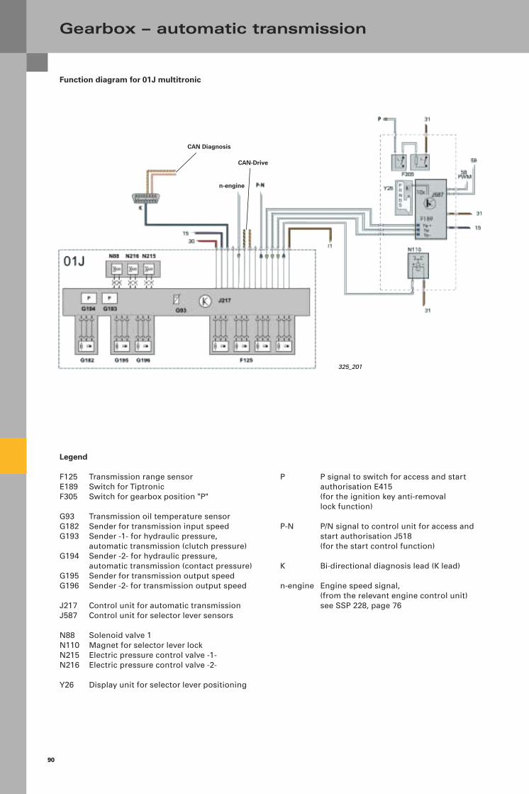
90
Function diagram for 01J multitronic
Gearbox – automatic transmission
Legend
F125 Transmission range sensorE189 Switch for TiptronicF305 Switch for gearbox position "P"
G93 Transmission oil temperature sensorG182 Sender for transmission input speedG193 Sender -1- for hydraulic pressure,
automatic transmission (clutch pressure)G194 Sender -2- for hydraulic pressure,
automatic transmission (contact pressure)G195 Sender for transmission output speedG196 Sender -2- for transmission output speed
J217 Control unit for automatic transmissionJ587 Control unit for selector lever sensors
N88 Solenoid valve 1N110 Magnet for selector lever lockN215 Electric pressure control valve -1-N216 Electric pressure control valve -2-
Y26 Display unit for selector lever positioning
P P signal to switch for access and start authorisation E415 (for the ignition key anti-removal lock function)
P-N P/N signal to control unit for access and start authorisation J518 (for the start control function)
K Bi-directional diagnosis lead (K lead)
n-engine Engine speed signal, (from the relevant engine control unit) see SSP 228, page 76
CAN Diagnosis
CAN-Drive
325_201
n-engine


32
5
Service TrainingVorsprung durch Technik www.audi.co.uk
All rights reserved. Subject to technical change.
CopyrightAUDI AGI/[email protected] +49-841/89-36367
AUDI AGD-85045 IngolstadtTechnical release 01/04
Printed in GermanyA04.5S00.08.20
AUDI A6 ‘05 Assemblies
Self-Study Programme 325