formal specifications and analysis of the computer-assisted
TRANSCRIPT
Int J Softw Tools Technol Transfer (2004) 5: 308–319 / Digital Object Identifier (DOI) 10.1007/s10009-003-0132-7
Formal specifications and analysis of the computer-assistedresuscitation algorithm (CARA) InfusionPumpControlSystem
Rajeev Alur1, David Arney1, Elsa L. Gunter2, Insup Lee1, Jaime Lee3, Wonhong Nam1, Frederick Pearce3,
Steve Van Albert3, Jiaxiang Zhou1
1University of Pennsylvania, Department of Computer and Information Science, Levine Hall, 3330 Walnut Street,Philadelphia, PA 19104-6389, USAe-mail: {alur,arney,lee,wnam,jiaxiang}@cis.upenn.edu2New Jersey Institute of Technology, NJIT-CCS, Computer Science Department GITC 4400, University Heights,Newark, NJ 07102, USA; e-mail: [email protected] Reed Army Institute of Research, 503 Robert Grant Ave., Silver Spring, MD 20910-7500, USAe-mail: {Jaime.Lee,Frederick.Pearce,Steve.VanAlbert}@na.amedd.army.milPublished online: 16 April 2004 – Springer-Verlag 2004
Abstract. Reliability of medical devices such as theCARA Infusion Pump Control System is of extremeimportance given that these devices are being used onpatients in critical condition. The Infusion Pump Con-trol System includes embedded processors and accom-panying embedded software for monitoring as well ascontrolling sensors and actuators that allow the embed-ded systems to interact with their environments. Thisnature of the Infusion Pump Control System adds tothe complexity of assuring the reliability of the totalsystem. The traditional methods of developing embed-ded systems are inadequate for such safety-critical de-vices. In this paper, we study the application of for-mal methods to the requirements capture and analysisof the Infusion Pump Control System. Our approachconsists of two phases. The first phase is to convertthe informal design requirements into a set of refer-ence specifications using a formal system, in this caseEFSMs (Extended Finite State Machines). The sec-ond phase is to translate the reference specificationsto the tools supporting formal analysis, such as SCRand Hermes. This allows us to conclude properties ofthe reference specifications. Our research goal is to de-velop a framework and methodology for the integrateduse of formal methods in the development of embed-ded medical systems that require high assurance andconfidence.
Keywords:CARA system – Requirements formalization– Safety-critical systems – Formal methods – Softwareverification
This research was supported in part by ARO DAAD19-01-1-0473, NSF CCR-9988409, NSF CCR-0086147, NSF CISE-9703220,and SRC 99-TJ-688. POC: Insup Lee ([email protected])
1 Introduction
Medical devices with embedded processors are part ofsafety-critical systems that must be highly reliable andbuilt correctly with respect to the requirements. Suchembedded systems consist of a collection of componentsthat interact with each other and with their environmentthrough sensors and actuators. Embedded software isused to control these sensors and actuators and to provideapplication-dependent functionality. Demands on embed-ded systems have been increasing as microprocessors havebecome more powerful. This in turn requires more com-plicated supporting software that must also be verified.Embedded systems have traditionally been developed inan ad hoc manner by practicing engineers and program-mers. The existing technology for embedded systems doesnot effectively support the development of reliable androbust embedded systems. The effective development ofembedded systems requires a collection of tools to cap-ture requirements, to construct, analyze, and simulatespecifications, to generate and test implementations, andto monitor and check implementations at run time.The research goal of the UPenn/NJIT team is to de-
velop a framework and methodology for the integrateduse of formal methods in the development of embeddedmedical systems that require high assurance and confi-dence. Our approach is to apply the formal techniquesto different stages of system development, ranging fromrequirements capture to design specification and analy-sis to code generation and validation. This paper de-scribes our case study based on an infusion pump sys-tem developed at WRAIR (Walter Reed Army Instituteof Research). Figure 1 shows our approach, which con-sists of two phases. The first phase is to manually convertthe informal design requirements into the reference spe-

R. Alur et al.: Formal specifications and analysis of CARA 309
Fig. 1. Two-phase approach
cifications in EFSM (Extended Finite State Machines).The informal design requirements were supplied to us byWRAIR in the form of a tagged requirements documentwritten in informal English, together with a listing of133 questions and answers. The Q&A document amendedand overrode the original tagged requirements document.This first phase resulted in many new questions and an-swers as well as refinements to the requirements to re-move inconsistencies. The second phase is to manuallytranslate the reference specifications to the tools based onformal methods, such as SCR [5], CHARON [2], and Her-mes [3]. These tools have different strengths and weak-nesses, and they are used together to complement eachother. For example, SCR can provide us with coveragechecks, CHARON supports the modeling of hybrid sys-tems involving both discrete and continuous behaviors(as is needed to include a model of the patient in thesystem), and Hermes supports model checking of safetyproperties.The rest of the paper is organized as follows. Section 2
gives an overview of CARA and its components, Sect. 3shows the details of our EFSM translation of the Englishrequirements, Sect. 4 discusses our SCRmodel, Sect. 5 ex-plains the Hermes model, and, finally, Sect. 6 contains ourconclusions.
2 Overview of CARA
The computer-assisted resuscitation algorithm (CARA)is a system that determines the rate at which an infu-sion pump should infuse fluid such as saline into a patientsuffering from severe hypotension due to blood loss. The
Fig. 2. Overall structure of Infusion Pump System
CARA determines the rate based on the patient’s cur-rent blood pressure; the more severe the hypotension, themore rapidly the fluid is to be infused. CARA controlsa system that includes an M100 infusion pump from In-fusion Dynamics and a physiological monitoring device.The physiological monitoring device is the conveyor ofblood pressure information for the CARA, including datafrom potentially several different sources such as a non-invasive cuff, a pulse wave velocity sensor, or an arterialline pressure sensor. The CARA systemwill eventually beused in connection with combat casualties, and it seemsprobable that a device such as this will eventually becomepart of emergency medical equipment deployed for auto-mobile and industrial accidents.The CARA software system is the aim of our for-
mal reference specification analysis. The CARA softwarefunctions within a context that is described in Fig. 2. Thetotal Infusion Pump System consists of five components:CARA, pump, blood pressure sensor, caregiver, and pa-tient. CARA must interact with each of these compo-nents, and clarifying that interface is an important aspectof the reference specification. For the most part, in thiswork we have focused on formalizing and analyzing justthe reference specification of CARA. However, by model-ing (in Hermes and CHARON, for example) the caregiverand patient as part of the total infusion pump we are ableto capture requirements about their behavior upon whichthe correctness of CARA depends. This section brieflydescribes the functionality of individual components andtheir interfaces.
CARA. CARA will drive the infusion pump with theaim of raising the patient’s blood pressure and maintain-ing it at an acceptable level. The pump’s infusion speedwill be calculated by CARA based on the patient’s cur-rent blood pressure and the desired averageblood pressureset by the medical staff. A physiological device attached

310 R. Alur et al.: Formal specifications and analysis of CARA
to the patient will provide the algorithm with the patien-t’s current blood pressure information. The desired aver-age blood pressure will be set by an attending caregiver orleft at the default value of 70 mmHg. The reason for sucha minimal blood pressure set point is that CARA is ex-pected to be used, at least initially, in situations where theavailability of resuscitation fluid is quite limited and theremay be several patients to be treated. While 70mmHg isa lowbloodpressure, it is sufficient to ensure the survival ofpatients until they can be transported to better equippedcare facilities. The caregiver has the option of increasingthe set point if it is judged necessary.CARA communicates with the caregiver via alarm sig-
nals, messages that appear on a display screen, and userinput via soft buttons. The display screen shows the driv-ing voltage (and hence the flow rate) as determined bythe algorithm. Whenever a pump fault occurs (e.g., oc-clusion in the fluid tubing), appropriate alarm signals areactivated. The caregiver is responsible for removing thepump’s faults, and if they happen when the pump is be-ing controlled by CARA, the software releases its control.We have tried to abstract the interface so that it can spec-ify what a replacement pump would have to satisfy to beused instead of the M100.Blood Pressure Sensor. The blood pressure sensor isthe monitoring device that is the source of physiologicalsignals such as arterial blood pressure and cuff blood pres-sure. It will be attached to the patient and communicatethe signals to CARA. However, the design does not al-low for direct interface with the algorithm. Instead, alldata from the sensor are assumed to be stored in a sharedbuffer that the software will have access to. This allows fora more modular design that could enable greater flexibil-ity in using a variety of monitoring devices.Pump. The infusion pump is the device that moves fluidinto the patient. It has a variety of sensors and can trig-ger alarms if fault conditions occur. The pump has twomodes, manual and autocontrol. In manual mode, thepump speed is set with a switch built into the pump. Inautocontrol mode, the pumping speed is set by a controlvoltage from an external source.Caregiver. The caregiver represents the person that willbe in charge of the infusion, usually a doctor, nurse, ormedic. He or she can interact with the actual pumpingdevice via hardware buttons on the pump and with theCARA software via messages and soft buttons on a dis-play screen. He or she sets the desired blood pressure viasoft buttons on the display and sets a default flow ratedirectly on the pump for use by the pump when it is oper-ating in manual mode (not under the control of CARA).The caregiver also takes care of potential faults and fail-ures that may occur during infusion.Patient. The patient is the object in this system. Heor she is connected to the pump and the blood pressuresensor. Infusion is carried out depending on the patient’scurrent state, with the aim of rapidly restoring his or herintravenous volume and blood pressure.
3 Reference model specification of CARA inEFSM
As mentioned in the introduction, the first phase was toconvert the informal requirements to the reference formalspecifications.Researchers at Walter Reed Army Institute for Re-
search (WRAIR) provided us with two documents uponwhich our specification is based [13, 14]. These were therequirements list and a list of questions and answers. Therequirements document listed 228 requirements that thesoftware had to meet. For example, typical requirementsare [14]:
Requirement 8.1: If the Air OK signal remainslow for 10 secondsRequirement 8.1.1: An appropriate alarm mes-sage should be issued.
The questions document listed 133 questions and an-swers, which amended the requirements document. Thisformat led to some initial confusion as the questions docu-ment sometimes overruled the requirements. In order towrite our specification, it was necessary to use both docu-ments in concert. This problem was exacerbated when westarted adding our own questions to the list.The requirements documents and appended ques-
tions developed at WRAIR provide a fairly thoroughdescription of the desired behavior of the CARA sys-tem. However, they do not quite fit the standard, forexample, the Software Engineering Standard of the Eu-ropean Space Agency [9], for a user requirements docu-ment in a variety of ways. One of the problems we havein attempting to derive a system requirements docu-ment from the WRAIR requirements documents is thatthe WRAIR requirements documents contain statementsabout the operations CARA should perform internallyto achieve certain external behaviors. An example of thespecification of such internal behavior can be seen inRequirement 9:
Requirement 9: CARA should monitor the backEMF line from the pump to keep track of infusedfluids by polling immediately when the pump isplugged and then on every even 5-second clock in-terval while the pump remains plugged in.
The “even 5-second clock interval” refers to the value ofan internal clock. In our work, we considered the require-ments documents as a given, except where we requiredadditional clarification. Therefore, our specifications alsofall short of the standards for system requirements docu-ments because they deliberately contain a reflection ofall internal details described in the original requirementsdocuments.We started our translation by specifying the CARA
system using 21 Extended Finite State Machines (EF-SMs). An EFSM is a finite state machine with variables,and in our model the state machines communicate usingshared variables. Specifying the system in this way al-lowed us to generate a standard document that could be

R. Alur et al.: Formal specifications and analysis of CARA 311
referred to by each of the several teams working withthe system. Our goal in creating EFSMs was to cap-ture our understanding of the requirements documents ina precise and mathematically rigorous manner. We couldthen apply various formal analysis techniques by translat-ing EFSMs to other formalisms. The requirements docu-ments and questions were written in relatively nontechni-cal English and thus contained a number of ambiguities.In the course of creating the EFSMs, we generated 30questions identifying 4 inconsistencies, 12 instances of in-completeness, and 14 clarifications of terms.Inconsistencies arose when the requirements defined
behaviors that were contradictory or incompatible. Thesedefinitions appeared both in the tagged requirementsdocument and the questions. For instance, there were sev-eral exchanges requesting clarification on the fact that therequirements indicate that certain actions are to be takenif a beat-to-beat source is lost for more than 3min (Re-quirements 42 and 43), but the Q&A document says itshould be 2min (Question 120).Incompleteness is when the requirements did not spec-
ify a behavior that seemed to be necessary or that wasrequired by another behavior. Question 134 asks whetherwe can assume that we can detect the source of a BP
Fig. 3. Components of CARA module
reading, as it seemed to be assumed but was never statedexplicitly.Clarifications of terms were necessary as the WRAIR
team used medical terminology we were unfamiliar with.It was also necessary in cases where the English was am-biguous. For instance, one requirement stated that some-thing should be done on every even 5-s interval. We mod-eled the system so that this event happened at the 10-s,20-s, 30-s, etc. marks – the even (not odd) 5-s intervals. Itwas only after we asked for clarification that we knew thatthey meant it should happen every 5 s.
3.1 Overall structure of CARA
In addition to directly implying certain internal imple-mentation details, the requirements documents stronglysuggest a certain internal logical structure or compo-nents for any implementation. We now describe a logicaldecomposition of CARA into these modules and brieflyexplain their functionalities and the interfaces betweenthem. A graphical layout of the CARA components andtheir interfaces is depicted in Fig. 3. The components in-clude Caregiver Interface, Blood Pressure Monitor, Algo-rithm, and Pump Monitors.

312 R. Alur et al.: Formal specifications and analysis of CARA
The purpose of the Algorithm component is to controlthe infusion rate of the pump and keep track of infusion-related data in log files. A patient’s blood pressure is usedto compute the rate at which the pump will be infusing:the higher the blood pressure, the lower the flow rate. TheCARA algorithm controls the flow rate as long as thereare no complications in the pump’s operation. In case ofcomplications, control reverts to the manual operator orcaregiver.The Caregiver Interface unit has two functions. First,
it serves as a means of communication with a caregiver.It allows the caregiver to modify infusion parameters suchas the target blood pressure and also initiate and termi-nate the algorithm’s control of the pump. Second, it dis-plays and sounds error messages. There are two kinds oferror messages: pump malfunctions and patient/infusion-related error messages.The Blood Pressure (BP) Monitor relays vital data
(such as BP source, BP value, and infusion-related errors)from the BP sensors to the Algorithm and Caregiver In-terface units. The BP Monitor is designed to work withmultiple sources, such as arterial line, pulse wave vel-ocity, or cuff sensors, and it will automatically select the“best” source after corroborating them. It also calculatesthe change in the patient’s blood pressure and can triggera number of alarms.
Fig. 4. Detailed view of CARA components
The Pump Monitors check that the pump is function-ing correctly by verifying that it is plugged in and thatthe infusion process is within norms. There are individ-ual monitors for each of the key readings followed by themonitors. These include occlusion, impedance, back EMF(i.e., a measure of how fast the pump motor is pump-ing), continuity, and whether the pump is plugged in. Themonitors report data back to the Algorithm and may alsodirectly trigger alarms.
3.2 Modeling of CARA in EFSM
An EFSM is a finite state machine extended with a no-tion of variable where the labels on edges are guardedactions over variables. For a more detailed description ofEFSMs, including their decomposition into a hierarchy,their parallel composition, and concurrency semantics,see [11].The hierarchical structure within the four components
of CARA is shown in Fig. 4.
– The Pump Monitor is modeled as six EFSMs, whereMonitor Plugin, Monitor AirOk, Monitor OccOk, andMonitor Continuity are used by the monitor to checkif the input signal is available, and Monitor backEMFand Monitor Impedance are used to poll the flow rate
R. Alur et al.: Formal specifications and analysis of CARA 313
and infused volume and to poll the impedance duringpumping.– The BPMonitor is modeled as three EFSMs, which inturn include nested EFSMs: BP Detector is responsi-ble for determining the BP sources and BP value, BPHandler is used to handle the data and corroborate theBP Source, and BP Checker is used in Auto Controlstatus to report falling BP and BP slope. In the De-tector and Handler, different BP sources have differentEFSMs.– The Caregiver Interface has three subcomponents.Status Display shows pumping data and the currentmode of CARA and also reports any exceptional situ-ation. The I/O button subcomponent allows the care-giver to reset the set point value. Alarm Display showsmessages associated with current alarms.– The Algorithm is used to decide the current modeof CARA and to implement the polling algorithm. Itswitches from one mode to another according to thecurrent situation of the pump system. It also controlsthe pumping flow rate according to the control BPvalue.
Interfaces between the modules are modeled by globalvariables in the EFSMs. We specify which componentsread and write a particular variable and an English de-scription of its meaning. To prevent reuse of names,we prefix each variable name with a two-letter codefor the module. All variables are globally readable butonly writeable by a single module. Thus, if there isa condition that can be triggered by multiple mod-
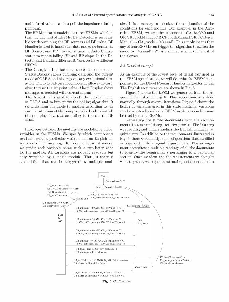
Fig. 5. Cuff handler
ules, it is necessary to calculate the conjunction of theconditions for each module. For example, in the Algo-rithm EFSM, we see the statement “CA_backManualOR CB_backManual OR CP_backManual OR CC_back-Manual→CA_mode =Manual”. This simplymeans thatany of four EFSMs can trigger the algorithm to switch themode to “Manual”. We use similar schemes for most ofthe alarms.
3.3 Detailed example
As an example of the lowest level of detail captured inthe EFSM specification, we will describe the EFSM com-ponents for the Blood Pressure Handler in greater detail.The English requirements are shown in Fig. 6.Figure 5 shows the EFSM we generated from the re-
quirements listed in Fig. 6. This generation was donemanually through several iterations. Figure 7 shows thelisting of variables used in this state machine. Variablescan be written by only one EFSM in the system but maybe read by many EFSMs.Generating the EFSM documents from the require-
ments list was a multistep, iterative process. The first stepwas reading and understanding the English language re-quirements. In addition to the requirements illustrated inFig. 6, there were multiple sets of questions that modifiedor superceded the original requirements. This arrange-ment necessitated multiple readings of all the documentsto identify the requirements pertaining to a particularsection. Once we identified the requirements we thoughtwent together, we began constructing a state machine to

314 R. Alur et al.: Formal specifications and analysis of CARA
Fig. 6. Requirements for cuff handler in auto control
implement those requirements. After several iterations ofthis process, we finalized the set of EFSMs presented inpart in this document.The requirements listed in Fig. 6 are not implemented
entirely in the Cuff Handler EFSM. There is anotherEFSM (not shown) that assigns the control BP and han-dles validation of BP sources, and there are a numberof other EFSMs involved. The correspondence from re-quirements to the EFSM is fairly straightforward. Re-quirements 27.1 through 27.4 pertain to setting the BPsampling rate, and they correspond to the four transi-tions from “Cuff in AC” to “Cuff Frequency”. Require-ment 44.3.1.3 corresponds to the transition from “Cuff In-valid 1” to “In Auto Control”, specifically the statement“CB_backManual = true”, which triggers the Algorithmcomponent to return to manual mode.As we used the EFSMs to create models in the various
tools, we found a number of errors or ambiguities in our
Fig. 7. Variables of cuff handler EFSM
EFSMmodel. These were corrected and the results of themodeling were also fed back into the EFSMmodel. Whilethere was a degree of overhead in creating and maintain-ing the EFSM documents, they were an extremely usefultool in helping to maintain conformity between the vari-ous models. They were also useful in facilitating commu-nication between the various teams using each tool.
3.4 EFSMs as specifications
There are some issues concerning the appropriateness ofusing EFSMs as system requirements. In appearance, EF-SMs are highly operational in nature. They appear tospecify not only what behavior is required of the systembut how the system is to achieve that desired behav-ior. It is indisputable that they strongly suggest a par-

R. Alur et al.: Formal specifications and analysis of CARA 315
ticular path of implementation. However, the extent towhich they actually require a particular implementationdepends greatly upon the interpretation of the EFSMs asspecifications. One interpretation of an EFSM as a spe-cification is as a set of sequences of input and outputbehaviors, where a system satisfies the specification pro-vided all possible sequences of input and output behaviorof the system are within that set. With this interpreta-tion, the internal structure apparent in the EFSM is onlya suggestion of the internal structure an implementationmight have. The implementor is free to seek another ar-chitectural design. In this interpretation, EFSMs can beused as system requirements. This observation, however,is of limited use without some form of automated supportfor extracting the I/O relation in a?form that is compre-hensible to the human readers.If the interpretation of the EFSM is a stronger specifi-
cation where not only the sequence of values for the inputand output variables are recorded but also the sequence ofvalues for all (global) internal variables, then the internalstructure ceases to be a suggestion and in effect becomesa requirement of any system implementation of it. In thiscase, the EFSM has slid from the role of system require-ment to that of architectural design. In our constructionof the EFSM specification of CARA, it was our intentionthat either interpretation could be applied as was foundappropriate and thus, within the limitations of remain-ing faithful to the original requirements documents, thatthey could be used in either the capacity of total systemrequirements or as a lower-level architectural design, asany teamworking on the CARA specification would deemappropriate.
4 CARA in SCR
SCR (Software Cost Reduction) is a formal requirementsmethod developed at NRL [6, 7]. It is designed to be usedby engineers for specifying requirements of complete sys-tems as well as software. SCR consists of a specificationeditor, a simulator, and a set of analysis tools. The specifi-cation editor allows information about the systemtobe en-tered in a tabular form, and there are tools for generatinga number of visualizations of the design. The editor auto-matically generates Java code that can be run in the simu-lator to get immediate feedback on the effects of changinginput variables. SCR represents the systemas a finite stateautomaton and defines transitions, input and output vari-ables, and events in terms of that automata.
4.1 Modeling in SCR
Our SCRmodel of the CARA system incorporates 20 sep-arate automata that can be viewed as working in parallel.Each automaton corresponds roughly to a machine in theEFSM model. The complete model uses 65 monitored(externally controlled) variables, 13 term variables, and
38 controlled variables. Mode transition tables are rep-resented in SCR’s tabular notation with three columns,one each for starting state, transition condition, and endstate. This allows users to model state machines by sim-ply putting the information in the right boxes. A statewith two exit transitions would have two rows with dis-joint transition conditions and destination states but thesame starting state. Other tables allow definitions of vari-ables, types, and functions.Initially, we expected that converting our EFSMs into
the SCR formatwould be a fairly straightforward task.Werecognized that this problem does not exactly fit the do-main of SCR,butwe felt thatwe could learnvaluable infor-mation about the system using SCR. There is an import-ant assumption implicit in the SCR system that caused ussome difficulty. This is the One-Input Assumption.
A basic assumption, called the One-Input Assump-tion, is that exactly one input event occurs at eachstate transition [5].
The One-Input Assumption requires that every statetransition be triggered by an input event – an event thatarrives from the environment of the state machine. Sinceour EFSMs have transitions that are not triggered by thearrival of an event, we were unable to simply transfer theEFSMs into SCR.This problem arises because SCR is designed for cap-
turing black box requirements. We hoped to utilize SCRto capture the formal requirements intended by the set ofEnglish language informal requirements we already had.This approach would allow us to use SCR to better definethe interfaces between the purely internal components –such as the algorithm for choosing a blood pressure source– and the external components like the blood pressuresensor. Since the English language requirements we weregiven included a large amount of information about theinternal structure of the CARA system, we found it diffi-cult to fully capture the model in SCR.In the BP Monitor system there is an EFSM that
reads and validates the data from the arterial line
Fig. 8. Tabular format of SCR
316 R. Alur et al.: Formal specifications and analysis of CARA
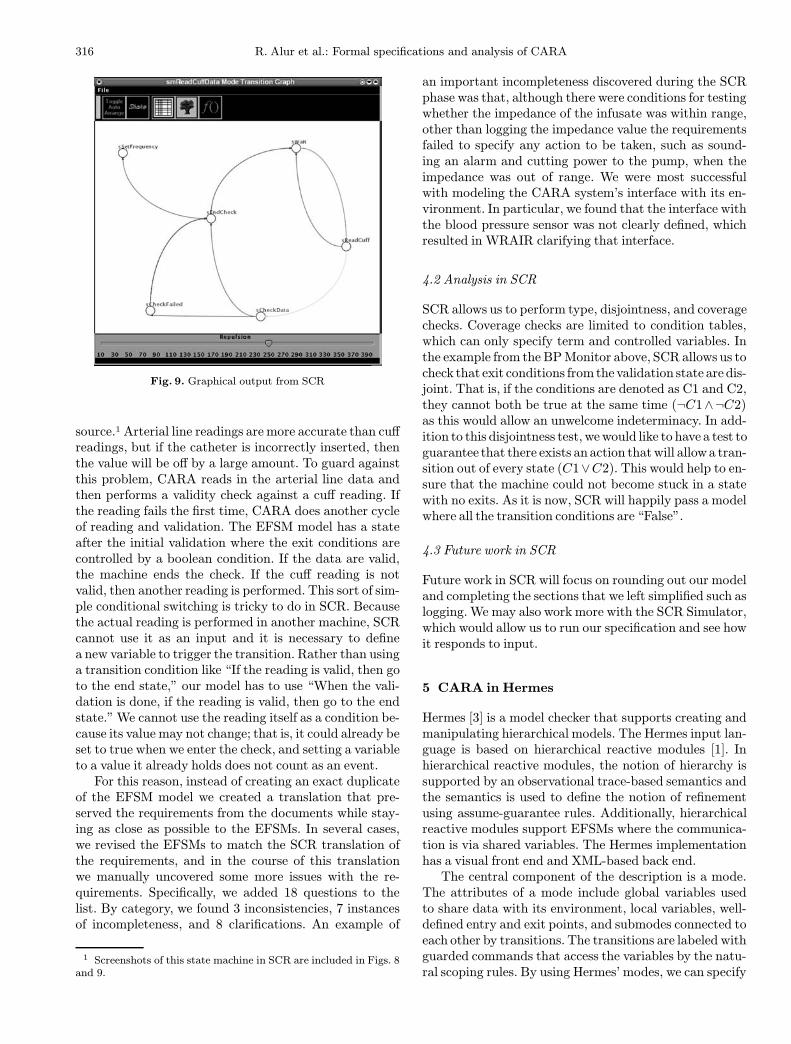
Fig. 9. Graphical output from SCR
source.1 Arterial line readings are more accurate than cuffreadings, but if the catheter is incorrectly inserted, thenthe value will be off by a large amount. To guard againstthis problem, CARA reads in the arterial line data andthen performs a validity check against a cuff reading. Ifthe reading fails the first time, CARA does another cycleof reading and validation. The EFSM model has a stateafter the initial validation where the exit conditions arecontrolled by a boolean condition. If the data are valid,the machine ends the check. If the cuff reading is notvalid, then another reading is performed. This sort of sim-ple conditional switching is tricky to do in SCR. Becausethe actual reading is performed in another machine, SCRcannot use it as an input and it is necessary to definea new variable to trigger the transition. Rather than usinga transition condition like “If the reading is valid, then goto the end state,” our model has to use “When the vali-dation is done, if the reading is valid, then go to the endstate.” We cannot use the reading itself as a condition be-cause its value may not change; that is, it could already beset to true when we enter the check, and setting a variableto a value it already holds does not count as an event.For this reason, instead of creating an exact duplicate
of the EFSM model we created a translation that pre-served the requirements from the documents while stay-ing as close as possible to the EFSMs. In several cases,we revised the EFSMs to match the SCR translation ofthe requirements, and in the course of this translationwe manually uncovered some more issues with the re-quirements. Specifically, we added 18 questions to thelist. By category, we found 3 inconsistencies, 7 instancesof incompleteness, and 8 clarifications. An example of
1 Screenshots of this state machine in SCR are included in Figs. 8and 9.
an important incompleteness discovered during the SCRphase was that, although there were conditions for testingwhether the impedance of the infusate was within range,other than logging the impedance value the requirementsfailed to specify any action to be taken, such as sound-ing an alarm and cutting power to the pump, when theimpedance was out of range. We were most successfulwith modeling the CARA system’s interface with its en-vironment. In particular, we found that the interface withthe blood pressure sensor was not clearly defined, whichresulted in WRAIR clarifying that interface.
4.2 Analysis in SCR
SCR allows us to perform type, disjointness, and coveragechecks. Coverage checks are limited to condition tables,which can only specify term and controlled variables. Inthe example from the BPMonitor above, SCR allows us tocheck that exit conditions fromthe validation state are dis-joint. That is, if the conditions are denoted as C1 and C2,they cannot both be true at the same time (¬C1∧¬C2)as this would allow an unwelcome indeterminacy. In add-ition to this disjointness test, wewould like to have a test toguarantee that there exists an action thatwill allowa tran-sition out of every state (C1∨C2). This would help to en-sure that the machine could not become stuck in a statewith no exits. As it is now, SCR will happily pass a modelwhere all the transition conditions are “False”.
4.3 Future work in SCR
Future work in SCR will focus on rounding out our modeland completing the sections that we left simplified such aslogging.We may also work more with the SCR Simulator,which would allow us to run our specification and see howit responds to input.
5 CARA in Hermes
Hermes [3] is a model checker that supports creating andmanipulating hierarchical models. The Hermes input lan-guage is based on hierarchical reactive modules [1]. Inhierarchical reactive modules, the notion of hierarchy issupported by an observational trace-based semantics andthe semantics is used to define the notion of refinementusing assume-guarantee rules. Additionally, hierarchicalreactive modules support EFSMs where the communica-tion is via shared variables. The Hermes implementationhas a visual front end and XML-based back end.The central component of the description is a mode.
The attributes of a mode include global variables usedto share data with its environment, local variables, well-defined entry and exit points, and submodes connected toeach other by transitions. The transitions are labeled withguarded commands that access the variables by the natu-ral scoping rules. By using Hermes’ modes, we can specify

R. Alur et al.: Formal specifications and analysis of CARA 317
hierarchically the EFSM’s modules including variables.The language distinguishes between a mode definitionand a mode reference, which allows sharing and reuse.Assertions associated with control points or modes andwith systemwide invariants can be used to specify desiredsafety properties.Using Hermes we can specify the Infusion Pump Sys-
tem hierarchically and various properties as boolean val-ued expressions. Hermes exhaustively explores the statespace to determine whether the Infusion Pump Systemsatisfies the properties. Consequently, Hermes either ver-ifies the property or provides a counterexample.
5.1 Modeling
Our Hermes model consists of 30 modes executingconcurrently and representing the five components ofthe Infusion Pump System: CARA, pump, caregiver,blood pressure sensor, and patient. A screenshot ofthe top level of our model in Hermes can be foundin Fig. 10. In order to derive a Hermes model fromEFSM, we need to restrict variables to finite types– boolean, enumerated types, and bounded integers.States and transitions are almost the same as theEFSM’s.In this paper, we explain two example modes of the
Hermes model: the Mode_Control_Algorithm mode andthe Polling_Algorithm mode. Figure 11 describes theMode_Control_Algorithm mode. In the Mode_Control_Algorithm mode, we specify the four states of CARA– wait, manual, autocontrol init , and autocontrol – andthe Ask_StartAC submode. While the transition labelsare not made visible in the Hermes display, they havebeen translated from the transition labels of EFSM. In
Fig. 10. Top level of Hermes model
Fig. 11. Mode_Control_Algorithm mode
Fig. 12. Polling_Algorithm mode
the Ask_StartAC submode, the setpoint value can bechanged andAutocontrol_Init may be entered by pushingthe StartAC button.The Polling_Algorithm mode is shown in Fig. 12. This
mode consists of two kinds of submodes, Polling_Back_EMF and Polling_Impedance. The polling algorithm isdesigned to monitor back EMF and impedance values.The impedance is polled immediately after the back EMFpolling, and the back EMF polling and impedance pollingare tried at most three times if they fail. If the back EMFor impedance reading cannot be obtained or is zero, theappropriate alarm must be sounded.

318 R. Alur et al.: Formal specifications and analysis of CARA
5.2 Analysis
Hermes has two mechanisms for describing the require-ments of a system. A point in a mode of a Hermes modelcan be given an assertion condition. This is a boolean val-ued expression that must be true whenever that pointis active. An example of such an assertion is that atthe Manual_Mode point of the Mode_Control_Algorithmmode, we always have CA_Mode =Manual . A mode canalso be given an assertion condition that must be truewhenever any point in the mode is active.We verified thatthe following assertions are satisfied on the correspondingpoints in modes.
– (CA_Mode =Manual) at Manual_Mode point of theMode_Control_Algorithm mode.– (PPu_PlugIn = true) at PlugIn point of theMonitor_PlugIn mode.– (PPu_PlugIn = true) ∧ (PPu_AirOK = true) atAirOK point of theMonitor_AirOK mode.– (PPu_PlugIn = true)∧ (PPu_OccOK = true) at Oc-cOK point of theMonitor_OccOK mode.– (PPu_PlugIn = true)∧ (PPu_ContinuityOK = true)at ContinuityOK point of the Monitor_Continuitymode.– (PPu_PlugIn = true) ∧ (PPu_backEMF_positive =true) at backEMFOK point of the Monitor_backEMFmode.– (PPu_PlugIn = true)∧ (PPu_Impedance_positive =true) at ImpedanceOK point of the Monitor_Impedance mode.
Furthermore, a system also can be given an invari-ant that is a boolean valued expression like an assertioncondition. An invariant, however, must evaluate to truefor all the states of a system, no matter which modes orpoints are active. An example of a systemwide invariantone could test is CB_Alarm_BPLow = false . This invari-ant means that CB_Alarm_BPLow is always false, thatis, BPLow alarm is never sounded. In this case, we do notwant it to always be true; we are actually testing that itis possible for the alarm to sound. Hermes verifies thatthe invariant does not hold with respect to the InfusionPump System and gives a counterexample that showsa path where CB_Alarm_BPLow becomes true. The pathis useful for designers to make sure of their design. Wechecked the following false invariants and got counterex-ample paths to reach the states where the invariants arefalse.
– CA_Mode �=AUTO– CB_Alarm_BPLow = false– CB_Alarm_belowSP = false– CB_Alarm_Slope = false– CB_Alarm_PollEMF = false– CB_Alarm_PollImp = false– CB_Alarm_BPInvalid = false– CB_Alarm_AllLost = false– CB_backManual = false
There are limitations to the verification capabilitiesof Hermes. At present, Hermes is most useful for findingcounterexamples to false conjectures. For verifying trueassertions on a system of the size of the Infusion PumpSystem, with the current version of Hermes we encounterthe state explosion problem and Hermes fails to success-fully terminate. Future versions of Hermes may be ableto remedy this problem, at least for systems of this size.Another limitation of Hermes is inherent in the system. Itallows us to test various safety properties provided thatwe can formulate the safety properties as boolean expres-sions of values of the system variables. However, it doesnot allow us to guarantee liveness properties. In general,we cannot use Hermes to prove that eventually some goodstate will be reached. For this a system with a more ex-pressive logic would be required.
6 Related work
Below we describe other work that has been done tomodel real-world systems using finite state machine tech-niques and to use that model to verify properties of thosesystems, and we discuss some of the differences betweenthat work and ours.In [4], Heitmeyer et al. describe their effort to prove
system invariants for the software requirements specifi-cation for a?weapons control panel. The main emphasisof this work is to describe a set of abstraction techniquesthat could be applied automatically to reduce the size ofthe model to render it practical for purposes of modelchecking. Properties in the abstract model were checkedusing Spin through an automatic call from SRC. Oncea counterexample was found in the abstract model, it wastranslated back to the full model and tested using simula-tion in SCR. One major difference between this work andours is that we had to begin with a specification documentwritten in English prose, with a sequence of modifyingand overriding appendices, while the software require-ments specification with which they worked was a?muchmore complete and precise semiformal description neededin a “build-to” specification, including such things as list-ing of input and output variables and a description of out-put values as a function of inputs. Developing a detailedformal software requirements specification from informalEnglish narrative was part of our endeavor. Also, in thatpaper the properties that were checked were state invari-ants (true in every state with no reference to earlier orlater states) and transition invariants (true of all pairs ofpre- and poststates of all transitions). Here, we are build-ing a framework to allow broader classes of propertiesto be checked, possibly using different tools, but alwaysbased on the same model.In [10], an example is given of a formal specification
of the mode logic of a flight guidance system. The specifi-cation utilizes a formalization based on that of SCR withseveral extensions such as transition buses and hierarch-

R. Alur et al.: Formal specifications and analysis of CARA 319
ical organization. This extended formalism is essentiallythe same as the EFSM formalism used in this paper. Inthat work, however, the formalism is incomplete in thatit lacks a?complete formal semantics, particularly for con-current hierarchical finite state machines. This work pro-vides a thorough system description but does so usinginformal syntax, which did not allow for any automatedchecking of properties of the specification.The work in [8] describes the application of the SCR*
tool set to a communications security (comsec) device.After converting prose requirements to SCR, the authorswere able to check consistency and completeness with theSCR tools and prove properties about the system by plug-ging SCR into the SPIN model checker and TAME/PVStheorem prover. The CARA system is significantly largerthan the comsec device (116 variables vs. 39), but the de-tails of modeling in this formalism are basically the same.Their work took a set of English language requirementsand generated an SCR model. This differs from our work,where we took English language requirements, generateda mathematical model in EFSM notation, then translatedthe EFSM model into a number of formalisms, includingSCR. This sped up modeling significantly and facilitatedusing SCR in parallel with other tools.The approaches summarized above all model the parts
of the specification that describe the external behavior ofthe system. Our approach attempts to extend this blackbox description by capturing the parts of the naturallanguage requirements that describe explicitly, and occa-sionally implicitly, the internal functioning of the system.
7 Conclusion
We have described our ongoing project using formalmethods tools for the specification and analysis of theCARA-based infusion pump system. Our preliminarywork is based on SCR and Hermes. As mentioned in thepaper, we were able to discover several inconsistenciesand incompleteness in the informal requirements thatwere provided to us for our study.The current work is to identify safety properties that
CARA should satisfy and to model check them using Her-mes. Another ongoing effort is to model the system usingCharon [2]. Charon is a language for modular specifi-cation of interacting hybrid systems based on the notionsof agent andmode. Hybrid systems exhibit behaviors thatare continuous as well as discrete. The infusion systemcan be naturally specified as hybrid systems. The mainadvantage of using Charon is that the reference specifi-cation in EFSM can naturally be described in Charonwithout any changes. In addition, it is possible to spec-ify explicitly the model of a patient (based on the knowncontinuous flow model of a human heart) and analyzethe infusion pump system with a given particular type ofpatient.
While the Cleanroom process [12] was used in develop-ing the initial English language requirements at WRAIR,it did not employ the type of formal modeling and ana-lyis techniques such as model checking that we have de-scribed in this paper. Ideally, such formal methods andanalysis techniques should be applied from the beginningof the development process of safety-critical medical sys-tems such as CARA.
Acknowledgements. We would like to thank Alwyn Goodloe andJitka Stribrna for their participation during the initial developmentof EFSM and SCR specifications. We also would like to express ourappreciation to Paul Jones at FDA and David Hislop at ARO fortheir support and encouragement.
References
1. Alur R, Grosu R (2000) Modular refinement of hierarchic re-active machines. In: Proceedings of the 27th ACM symposiumon principles of programming languages, Boston, 19–21 Jan-uary 2000, pp 390–402
2. Alur R, Grosu R, Hur Y, Kumar V, Lee I (2000) Modularspecifications of hybrid systems in Charon. In: Proceedingsof the 3rd international workshop on hybrid systems: com-putation and control, Pittsburgh, 23–25 March 2000. Lecturenotes in computer science, vol 1790. Springer, Berlin Heidel-berg New York, pp 6–19
3. Alur R, Grosu R, McDougall M (2000) Efficient reachabil-ity analysis of hierarchical reactive machines. In: Proceedingsof the 12th international conference on computer-aided ver-ification, Chicago, 15–19 July 2000. Lecture notes in com-puter science, vol 1855. Springer, Berlin Heidelberg New York,pp 280–295
4. Heitmeyer C, Kirby Jr J, Labaw B, Archer M, Bharadwaj R(1998) Using abstraction and model checking to detect safetyviolations in requirements specifications. IEEE Trans SoftwEng 24(11):927–948
5. Heitmeyer CL, Jeffords RD, Labaw BG (1996) Automatedconsistency checking of requirements specifications. ACMTrans Softw Eng Methodol 5(3):231–261
6. Heninger K, Parnas DL, Shore JE, Kallander JW (1978)Software requirements for the a-7e aircraft. Technical Report3876, Naval Research Lab, Washington, DC
7. Heninger KL (1980) Specifying software requirements for com-plex systems: new techniques and their application. Softw Eng6(1):2–13
8. Kirby J, Heitmeyer C, Archer M (1999) Scr: A practical ap-proach to building a high assurance comsec system. In: Pro-ceedings of the 15th annual computer security applicationsconference (ACSAC ’99), Phoenix, AZ, l6–10 December 1999.IEEE Press, New York, pp 109–118
9. Mazza C, Fairclough J, Melton B, de Pablo D, Scheffer A,Stevens R (1994) Software engineering standards. Prentice-Hall, Upper Saddle River, NJ
10. Miller SP (1998) Specifying the mode logic of a flight guidancesystem in CoRE and SCR. In: Proceedings of the 2nd work-shop on formal methods in software practice. ACM Press, NewYork, pp 44–53
11. Penn CARA Team (2003) EFSM semantics. http://www.cis.upenn.edu/∼lee/hasten/cara/EFSMsemantics.pdf
12. Prowell SJ, Trammell CJ, Linger RC, Poore JH (1999) Clean-room software engineering: technology and process. Addison-Wesley, Reading, MA
13. WRAIR Dept. of Resuscitative Medicine (2001) CARA ques-tions. Proprietary Document, WRAIR, Silver Spring, MD,January
14. WRAIR Dept. of Resuscitative Medicine (2001) CARA taggedrequirements. Proprietary Document, WRAIR, Silver Spring,MD, March