formerly appendix s- intersection corner radii · s-1 intersection corner radii effective april...
TRANSCRIPT

S-1 Intersection Corner Radii Effective April 2016
1. Simple Curve Radius with Taper
Laying out a simple curve radius with taper may be done in a few easy steps as outlined below:
A. Based on the angle of turn and design vehicle, select the appropriate radius, offset and taper length (length to offset ratio) from Figure 5.2.5.2-a.
B. To find the center of the radius, offset the radius plus the offset distance from the outside edge of the approach and departure legs. Draw a circle equal to the radius and snap the center to the point of intersection as shown in Figure 1-a.
Figure 1-a Simple Curve Radius and Taper Design
Formerly Appendix S- Intersection Corner Radii

S-2 Intersection Corner Radii Effective April 2016
C. Draw a line from the center of the circle perpendicular to the approach and departure legs. Multiply the offset distance by the taper length. For example, if L:T is 20:1 and the offset is 4 feet, then the taper length equals 4’ x 20 = 80’. Offset the distance calculated (i.e. 80’) from the perpendicular lines as shown in Figure 1-b.
Figure 1-b Simple Curve Radius and Taper Design
D. From the point where the offset intersects the outside edge of the approach and departure legs, draw
a line back tangent to the circle as shown in Figure 1-c.
Figure 1-c Simple Curve Radius and Taper Design

S-3 Intersection Corner Radii Effective April 2016
E. Trim the circle at the PC and PT as shown in Figure 1-d.
Figure 1-d Simple Curve Radius and Taper Design
2. Three Centered Compound Curves
Laying out a three centered compound curve may be accomplished in a few steps as outlined below:
A. Based on the angle of turn and design vehicle, select the appropriate radii and offset from Figure 5.2.5.3-a.
B. To find the center of the center curve radius, offset the radius plus the offset distance from the outside edge of the approach and departure legs. Draw a circle equal to the radius and snap the center to the point of intersection as shown in Figure 2-a.
Figure 2-a Three Centered Compound Curves Design

S-4 Intersection Corner Radii Effective April 2016
C. Using the ‘Place Arc’ command and ‘Tangent’ snaps in AutoCad® or Microstation®, snap tangent to the departure leg and then snap tangent to the center circle as shown in Figure 2-b. Repeat steps to draw the arc on the approach leg.
Figure 2-b Three Centered Compound Curves Design
D. Trim the center circle to the arcs as shown in Figure 2-c.
Figure 2-c Three Centered Compound Curves Design

S-5 Intersection Corner Radii Effective April 2016
Figure 3-a Intersection Corner Design – Example 1

S-6 Intersection Corner Radii Effective April 2016
Figure 3-b Intersection Corner Design – Example 2

S-7 Intersection Corner Radii Effective April 2016
Figure 3-c Intersection Corner Design – Example 3
S-8 Intersection Corner Radii Effective April 2016
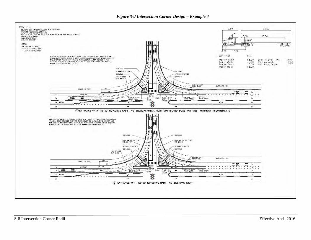
Figure 3-d Intersection Corner Design – Example 4