formula sae paddle shift system - ucf department … — the formula sae paddle shift system is a...
TRANSCRIPT

Formula SAE Paddle Shift System
Richard Pittman, Sean Feschak, Musab Hmeidan, Kevin Castillo
Dept. of Electrical Engineering and Computer Science, University of Central Florida, Orlando,
Florida, 32816-2450
Abstract — The formula SAE paddle shift system is a system design to be implemented on the UCF SAE formula race car that consists of other subsystems such as the GPS, gear position sensor, and data logger. The purpose of this system to assist the driver of the vehicle in performing better on the track by getting rid of the older stick shift system and replacing it with the paddle shifters for faster shifting. This project uses principles of control systems, electric circuitry, and computer programming in order to achieve the project goals.
Index Terms — Paddle shifters, relays, SAE formula, sensors.
I. INTRODUCTION Formula SAE is an international competition organized
by the Society of Automotive Engineers where college students design, manufacture and compete with a formula style car. The car built by UCF’s Formula SAE team uses a 2006-2007 Suzuki GSX-R600 engine that has a 6-speed sequential gearbox. The gears can only shift sequentially in order, and shifts are actuated by the rotation of a lever at the gearbox. The current shifting system is completely mechanical and is actuated by a lever mounted to the driver’s left side. This lever is attached to a push-pull cable which runs the length of the car to the gearbox. When a shift is needed the driver is required to remove his or her hand from the wheel, grab the lever, and push or pull it. This system is problematic in a few specific ways. The time taken between when the shift is needed to when it is actuated is somewhat slow due to the driver’s need to remove his or her hand from the wheel. The lever also proved to be difficult to actuate at certain critical times. On a Formula SAE competition course with many turns, frequent shifting is required to maximize performance. If a shift is needed during a turn the driver would have to make the turn with one hand on the steering wheel or simply wait until after the turn and lose time while the engine was in a bad RPM range. Both situations lead to a decrease in overall performance.
The goal of this project is to design and implement an electronic paddle shift system to address these issues and
eliminate the detriment of the push-pull system to overall performance in a race. With paddle shifting, the driver would be able to actuate a shift without removing his or her hand from the steering wheel, increasing control at every point in the race. As well, the amount of energy required by the driver to actuate the shift is minimized to reduce the fatigue of the driver during a race. This would ideally lead to faster shift times, a decrease in weight, and better performance overall. The system will be designed with increased performance, light weight, and reliability as the driving parameters. When finalized, it will allow the driver to actuate a shift almost instantaneously without losing any control of the car.
The team has come across a few features to be added that would make the project more proficient and would make both the vehicle and driver perform better such as adding more information to the dash display for the driver to analyze such as rpm, time, location, etc. Different micro-controllers have been introduced to the team which been investigated to pick the ones that seem to do the job. Different actuating systems have been investigated and the electric solenoid system have proven to be the most simple and inexpensive one over the hydraulic and pneumatic systems.
The electronic shift system is designed for the Formula SAE car so that the driver would be able to actuate a shift without removing his or her hand from the steering wheel, increasing control at every point in the race. As well, the amount of energy required by the driver to actuate the shift is minimized to reduce the fatigue of the driver during a race as compared to the current push-pull lever system being used. This leads to faster shift times, better performance overall and better driver control increasing the safety of the vehicle. The system is designed with long term performance and easy transferability in mind so that it can be easily transferred to the next year’s Formula SAE vehicle. The display system being used is to easily be read by the driver and it will inform them of which gear they are in as well as a shift indicator and will be able to withstand the harsh environments it will be exposed to. The system will also be logging the location of the vehicle, the rpms, gear and time so that the driver can review this information later and improve upon their performance.
II. OVERVIEW AND OPERATION
The design philosophy for the SAE paddle shifter system was to create a reliable, compact, and easy-to-troubleshoot paddle shifting system for better performance. The following list are the general specifications and design requirements:

1) system shall not exceed 5 pounds to prevent adding weight to vehicle 2) system’s components must be able to work in the approximate temperature range of 20 to 120 F 3) whole system has to run on the only battery of the vehicle. 4) the response of the paddle shifters and the gear shifting process must be fast in less than 500ms 5) system will data log of engine speed and gear position 6) system must be waterproof as well as being operational in different weathers and environment 7) the paddle system must rotate the shifter shaft by about 20 degrees to ensure the correct shifting process 8) the paddles must be made out of material that withstands excessive force without failing 9) the system will operate based of an electric actuator that is of linear specifications. 10) the system will have the ability to shift into neutral from any gear using a button 11) the system’s components must be small to be able to fit on the vehicle.
It has been planned to aim for the design and production of a durable and high quality product through this project and in order for this to happen a few specific goals and objective have been declared. The objectives for the project are to be accessible and easy to use, to be reliable and highly durable, to be maintainable, to be controllable, to be transferable, and to be safe. the electronic paddle shifters need to be a shifting system that does not require the driver to remove a hand from the steering wheel to perform a shift. The paddles used to shift will be located at the fingers of the driver in a comfortable position to make it more accessible. The system should be easily maintained and have parts that are easy and fast to replace if it is necessary to not limit the vehicle's performance on the tracks. since it is a vital to test this product and the restrain of having just one complete product, the product being transferable is very important. The maintenance team of the SAE car have to be granted the ability to take off the steering wheel with ease to fix any problems that might have occur during a race or on regular days. Since the SAE team is required to have a new vehicle designed every year differently than that of the previous year the electronic paddle shifter system has to be easy to remove and install.
III. ACTUATOR The motion required to shift the gears of the engine is a
simple bi-directional linear throw. It connects directly to the transmission shift mechanism and functions to replace the force generated by a human operator moving a
mechanical lever. In light of this, a significant amount of testing and research was directed towards choosing an appropriate linear actuator. In order to help us with selection of a linear actuator, we made a series of force measurements, as seen by Table 5 and Table 6. Both shifting up and shifting down forces were measured:
Table 1: Force table – shifting up.
Table 2: Force table – shifting down.
A. Electronic Actuator System
The electric actuator system was chosen because it features bi-directional motion, it does not involve storing a compressed gas or fluid on the vehicle, and in theory it is has infinite life. The electronic actuator system uses current to move a piston bi-directionally. Unlike the Hydraulic and Pneumatic systems, the electronic actuator’s power and force is simple to calculate. Giving the actuator power will yield a movement and the force of the actuator is based on the actuator datasheet. It is the motor and cylinder in one device. The correct electronic actuator, must provide force a factor above the force required to move the shifter so we chose accordingly.
FORCE TABLE FOR SHIFTING UP From
To Shifting Up Force (lbs)
1 2 12
2 3 11
3 4 11
4 5 11
5 6 11
FORCE TABLE FOR SHIFTING
DOWN From
To Shifting Down Force (lbs)
6 5 11
5 4 11
4 3 10
3 2 11
2 1 11
IV. POWER For this project, batteries are the main option for the
power source. Since this project includes a high voltage and low voltage power obligations for the components to be powered where the micro-controller requests to be power-driven by low voltage and other components of the vehicle require high voltage to be operational such as the headlights and the ECU, voltage regulators are a necessity for this type of situation. In this project, when using the term high voltage it is meant that it would be around the borders of 12 to 14 volts, since the vehicle will not be using high voltage rates at 700 volts and low voltage would mean 2-5 volts.
A. Battery In this project, using batteries was the only option to
power up the system since the vehicle will be mobile and that is the standard for powering such vehicles. The battery would be that of the 12-volts battery used in motorcycles since the engine and some of the external subsystems used on the formula car is that of a motorcycle. The battery chosen to be included in this design was of lithium specifications since it is much lighter than that of the regular lead acid batteries. The lithium-ion battery has higher energy density which is a potential for higher capacities.
B. Regulation
For this project, power conversion might need to be done to deliver the right amount of voltages and power up all components within the vehicle without any failures or burnouts. The only type of conversion that would necessary in this project is the DC-to-DC conversion since the vehicle’s main source of power is the 12 volt battery which is obviously a DC power source and the components of the system such as some of the micro-controllers needs to be supplied with 3.3 or 5 volts. A supply voltage in the standard range of 3.3 to 5 volts could be easily designed for the micro-controller using amplifiers, resistors, regulators, or other components to ensure the steady supply voltage. However, regulators seem to be the one component that is mostly favorable and usable by individuals. Initially, switching regulators have been closely examined and studied to be included in the design but they seem to be complicated for individuals who don’t have experience with electronics and would be hard to repair if broken. So linear regulators have been used in this project to power up the other subsystems that require regulation from 12 volts to the required power-up voltage of the components.
V. DISPLAY The function of the display for the shift system is to
inform the driver of what gear they are currently in. The display gets a signal from the gear position sensor to output a figure that corresponds to the current gear position the vehicle is running on. Two options have been studied for the display a LED 14-segment display or a LCD display but the team decided to go with the LED option so that the neutral output can be represented clearly.
A. LED Segment Display A fourteen-segment display is a type of display based
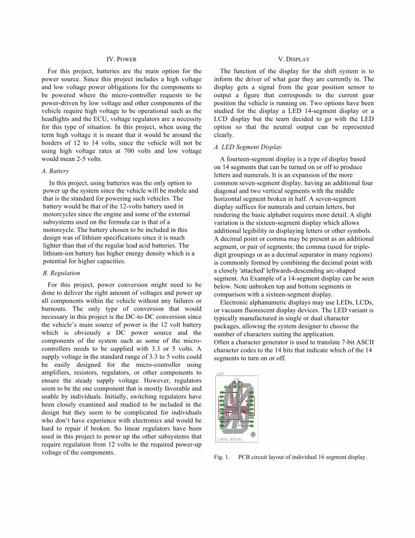
on 14 segments that can be turned on or off to produce letters and numerals. It is an expansion of the more common seven-segment display, having an additional four diagonal and two vertical segments with the middle horizontal segment broken in half. A seven-segment display suffices for numerals and certain letters, but rendering the basic alphabet requires more detail. A slight variation is the sixteen-segment display which allows additional legibility in displaying letters or other symbols. A decimal point or comma may be present as an additional segment, or pair of segments; the comma (used for triple-digit groupings or as a decimal separator in many regions) is commonly formed by combining the decimal point with a closely 'attached' leftwards-descending arc-shaped segment. An Example of a 14-segment display can be seen below. Note unbroken top and bottom segments in comparison with a sixteen-segment display.
Electronic alphanumeric displays may use LEDs, LCDs, or vacuum fluorescent display devices. The LED variant is typically manufactured in single or dual character packages, allowing the system designer to choose the number of characters suiting the application. Often a character generator is used to translate 7-bit ASCII character codes to the 14 bits that indicate which of the 14 segments to turn on or off.
Fig. 1. PCB circuit layout of individual 16 segment display.

Fig. 2. PCB layout sent to PCB manufacturing for multiple parts.
VI. DRIVER CONTROLS After investigating many types of motorsports and
production applications, three possible ways of activating a shift without removing one’s hands from the steering wheel were examined: buttons mounted on the face of the steering wheel, paddles mounted on the back of the steering wheel that rotate with the wheel, or fixed paddles mounted to the steering column. It was decided that the paddles will rotate with the wheel and be mounted slightly inward on the spokes of the steering wheel so that they could be easily reached by the driver’s fingers at all times, but would not be accidentally engaged during sharp turning maneuvers. A special button for neutral will be mounted on the front face of the wheel reachable by the drivers left hand thumb. The autocross courses that the FSAE car races on are very tight and often encompass quick back and forth turns. If the paddles were mounted to the column, they would have to be very large so that they would still be in reach of the driver’s hands during a sharp turn. Paddles mounted to the steering wheel can be much smaller because they can be placed such that they are always in the correct position relative to the driver’s hands. As per the industry “standard,” the left paddle will be used for downshifts, and the right for up-shifts.
VII. GEAR POSITION SENSOR
The gear position sensor is a very important component of the system. It is used to determine the gear of the transmission in order to display it to the LED display, and also used within the software control flow to ensure correct operation of the system. The gear position sensor itself is a rotary sensor with seven positions. Six of the positions have a set resistance value that corresponds to a specific gear, and the seventh position simply acts as a switch. The table below shows the resistance value that
represents each gear along with the voltage signal the control unit receives.
Table 3: Values that determine the shifts.
Two different methods have been approached for the implementation of the gear position senor but one was designed and included in the system due to the fact that it is easier and close to the specifications of the original design from the factory. The factory gear position doesn’t work with the design of the vehicle since some of the factory electrical subsystem of the vehicle has been modified. Reverse engineering has been applied to the factory gear position senor to examine and learn how it exactly works. it has been decided to make the sensor using the factory gear position sensor because it is simpler and easier to fix if it goes bad. additional electrical circuitry has been applied to the sensor so that it would function properly and the following diagram shows what has been done and designed in order for it to function properly.
Fig. 3. Gear position senor design and connection.
Gear Resistance (Ω) Voltage (V)
Neutral open 5
1 570 1.8
2 830 2.26
3 1500 3
4 2700 3.68
5 6800 4.38
6 15000 4.70

VIII. WIRING HARNESS
The electronic paddle shift system will require a wiring harness to connect all the components of the system that can withstand the demands of a motorsports environment. Getting electrical signals from point A to B is relatively straightforward but when it comes to a motorsports environment it is extremely important that the harness is constructed out of the most reliable and lightweight components. It is very common in the professional motorsports industry for wiring harnesses to be referred to as "mil-spec" (or military specification). This has evolved from aircraft and military specifications wherein lightweight and reliability are of the utmost importance. As motorsports evolved into an increasingly more sophisticated and expensive professional endeavor, specific motorsport connectors have evolved which are even lighter and smaller than their aerospace counterparts. These products don't have to meet OEM production testing requirements, they just have to be reliable in a racing environment which is not the same as the demands required by OEM's.
Fig. 4. Wiring harness connections.
A true mil-spec harness will only be made using high quality harnessing components and the proper tools and techniques. Some of the materials and components we used in our wiring harness build are: Tefzel wire, Raychem DR-25 heat-shrink tubing, Deutsch connectors,
Raychem boots and transitions, ResinTech RT125 harness epoxy, low static Kapton tape, and braided Kevlar lacing cord.
Fig. 5. Wiring harness conceptual design.
IX. GPS MODULE
The electronic paddle shift system makes use of a GPS subsystem to allow the driver to see where they can make improvements around a track. The purpose of the GPS module is so that users may test their best times around a track and attempt to improve their performance. The GPS module works closely with the MCU to produce formatted text output that is later uploaded to a visualizer that displays the gathered data in a graphical format via Google Maps.
A. MTK3339 GPS Receiver The MTK3339 GPS receiver is a very well rounded
GPS receiver. From its size to its cold startup time, the features it provides do not excel in any particular arena but provide a consistent user experience. Another useful feature the MTK3339 has is the ability to attach a larger antenna to the ANT pad. The MTK3339 comes with a standard ceramic patch antenna that provides the listed -165 dB sensitivity but a larger more sensitive antenna can be connected. When attaching a new active antenna the MTK3339 has the ability to automatically detect said antenna and automatically switch over and use the new antenna a feature that was extremely useful and absolutely necessary in this design. The MTK 3339 can also be purchased with a breakout board in order to make integrating the MTK3339 with a microcontroller much easier. The MTK3339 is compatible with most Arduino GPS libraries with the ability to parse data and query the built in GPS logging capability as well as various tutorials on how to use the MTK3339 and its data logger. The

MTK3339 has various features, both default and optional, that were very useful for this design and its software libraries solved many of the issues that may arose when attempting to assemble all of the components of this design.
Fig. 6. MTK3339 with breakout board.
B. GPSVisualizer Overlaying data in Google Maps is achieved after data
has been logged as formatted GPS data written to a txt file. By uploading the aforementioned txt file with all of the formatted GPS data to GPSVisualizer.com the user will be able to view their track run data in a colorized and interactive manner via Google Maps Appended to each point in the track will be a speed, time and current gear position of the vehicle. The track will be colorized based on speed using the following colors from slowest to fastest: red, yellow, green, teal, blue. GPSVisualizer has the ability to take raw NMEA 0183 GPS data and draw maps. For our uses we decided to use GPSVisualizer’s formatted text input due to the fact that we needed to append additional data to every point that is mapped. The formatted text input are html tables that are custom to GPSVisualizer’s interpreter.
Fig. 7. Example of mapped data using GPSVisualizer.
X. DATA LOGGING
Data logging takes place via the SD module that is attached to the MCU. With the SD module users have the ability to store data at any capacity they may require. The SD module uses a micro SD card to store processed data that is later used to display all of the logged data in a graphical manner using GPSVisualizer. In order to read the data from the micro SD card a micro SD adapter is used. The micro SD adapter allows most desktops and laptops to read the data from micro SD cards.
A. SD Module The SD module is connected directly to the MCU and
communicates with said MCU serially. The SD module is capable of reading from or writing to the micro SD that is connected to it. This module is used to store all of the data that the GPS visualizer requires from the GPS and gear position sensor. The MCU processes and formats the data for GPSVisualizer before storing it on the micro SD. The user can later disconnect the micro SD card from the SD module and use an adapter to upload the collected data to GPSVisualizer via their homepage.

Fig. 8. Adafruit MicroSD card breakout board that was used.
XI. MCU
The MCU we decided to use was the Arduino Uno (Atmega 328) due to its relative ease of use and compatibility with our other components. The MCU is responsible for connecting almost every aspect of our design from the GPS to the shifting solenoid almost all of the data passes through the MCU.
One situation where the MCU works with various other components of the vehicle is the scenario where immediately prior to shift actuation, both spark and fuel need to be restricted so that a ‘flat shift’ can be performed. Flat shift is a term which describes the event where the engine speed is retarded, eliminating the need for the driver to lift off of the accelerator while shifting. This function will allow for a faster and more accurate shift when compared to conventional means where the driver must lift off of the accelerator.
Fig. 9. PCB circuit layout for the Atmega 328P-20 with the Voltage Regulator.
A. Software Development Strategy The software development method that was adopted for
this design was an Agile software development approach. One of the reasons for the aforementioned Agile software development approach is the fact that it allows for much more flexibility and agility when working on relatively large and complex projects. The fact that many members of the group had never worked with global positioning modules and data logging means that the program’s specifications were constantly changing in order to meet the design requirements and work with various design constraints. Developing in an Agile manner also allowed the design team to work with the fixed timescale that is provided via the Senior Design II due date. Agile development permitted the program to evolve and adapt with more ease as requirements were modified and the project moved forward. Another benefit of adopting an Agile development method is the fact that the software was tested continuously throughout its development cycle. The aforementioned integrated testing was essential to this design due to the fact that the design team is relatively inexperienced with global positioning software design as well as microcontroller programming at the scale of this project. The relatively limited timeframe of this project means that integrated testing was crucial to refining the project’s software design. The Agile software development style also works very well with the design team dynamic that was in place. The previously mentioned design team dynamic was one where the members of a small team are all committed to the project, constantly involved in the project and are consistently communicating in a relatively casual manner about the project and its design. The Agile development format also allowed for active involvement of an outside party such as a supervising professor or members of the University of Central Florida formula one SAE club. The relative ease of rapid modification that agile provides was useful when working with outside parties because it allowed said parties to suggest changes or additions to the project software and ultimately allow the design team to actually implement said changes or additions in a timely and effective manner.
All in all, an Agile software design approach suited this project extremely well. From the small team dynamics that are in place to the rapid modification of project guidelines an Agile software design approach accommodates the aforementioned requirements and ultimately streamlined the development of the software for this project.

Fig. 10. Flow diagram for MCU and peripherals.
XII. CONCLUSION
The previous two semesters seemed to be very valuable and a good experience for the team. Being forced to work in an environment where correlation between others a team has given the chance for the individual members to promote important skills that will be needed in pursuing our individual goals in the future. Of the many skills attained from this project are writing technical papers, performing presentations and most importantly, working coherently in a group setting. One of the most rewarding experiences was understating and appreciating the amount of work and research that went into designing and building the system. Also an important note to point out is of the fact that previous information taught and discovered that has been attained in the past coursework all these years during the educational career has been implemented by the help of working on this project.
ACKNOWLEDGEMENT The design team has sought out the help and
consultation of professors and engineers throughout the process of designing the paddle shifting system and so the team is thankful for all their contributions towards this project and would like to specifically acknowledge Dr. Samuel Richie and Dr. Chan. The team wish to acknowledge the assistance of the TI lab staff at UCF.
REFERENCES [1] TE connectivity. (2001). Hand Cable Laying. Retrieved 19
July, 2015 from https://www.rbracing-rsr.com/downloads/wiring_pdfs/twisted_harness.pdf
[2] Adafruit. (2014). MicroSD card breakout board+. Retrieved August 1, 2015 from http://www.adafruit.com/products/254
BIOGRAPHY Richard Pittman will graduate with his Bachelor’s of Science in Electrical Engineering in December of 2015. He plans to pursue a career in automotive motorsports engineering, and is currently a member of the UCF Formula SAE team and a student member of SAE International.
Sean Feschak will graduate with his Bachelor’s of Science in Electrical Engineering in December of 2015 and earned his Bachelor’s of Science in Mechanical Engineering in May of 2012.
Kevin Castillo will graduate with his Bachelor’s of Science in Computer Engineering in December of 2015. Kevin’s goals are to acquire a job in the local Orlando area with a software company. Musab Hmeidan is a senior graduating in Fall 2015 with a Bachelor's degree in Electrical Engineering. He has an interest in analog devices and control systems and plans to pursue his master’s in either control systems or microelectronics.