formulas, processes, and petri-nets applied to the ... · formulas, processes, and petri-nets...
TRANSCRIPT
Formulas, processes, and Petri-Nets applied to the specification and verification of a HDLC protocol
M.Duque Ant6n, M.Bretschneider*
Philips GmbH Forschungslaboratorium Hamburg Vogt-Koelln-Str.30, D-2000 Hamburg 54
Abstract
In specifying a variant of a HDLC protocol we illustrate a method that addresses three problems: decomposition of a complex system into simple components, hierarchical design of a protocol starting from the service specification and resulting in the protocol description and, finally, modular verification of the protocol w.r.t, the service specification. The theoretical basis is given by Process Theory. Descriptions of basic protocol functions are obtained considering projections of the global protocol behaviour onto 'locally' relevant sets of events. Composition- ality of semantics allows reasoning about complete (protocol-)components by induction over properties of their constituents. To formalize behaviour we use formulas, process terms and Petri-Nets.
I n t r o d u c t i o n
The logical structure of communication protocols conceived today is very involved. This applies in particular to protocols associated with the Open System Interconnection reference model, OSI (c.f. [ISO]). Their descriptions are made up of lists of many different functions displaying an intricate proportion of interaction and parallelism. This calls for elaborated construction methods.
There are currently many research efforts being made to overcome these problems. They are related to the development of techniques for design, specification and verification. This paper focusses on a design technique that is based on two basic ideas: progressing from one design step to the next one utilizes the concept of an external and an internal view of an entity. One first depicts this entity as seen externally, afterwards detailing the internal structure. To check the consistency of both views the communication between inner constituents are concealed and the resulting behaviour is proven to be as specified by the external view. The approach comprises the concept of layers in the OSI reference model.
In order to characterize individual components one first picks out their different functions and to assist construction one specifies them separately. This supports the understanding of intuitively clear building blocks. Existing components can be used instead of designing them from scratch. In this respect a top-down refinement and a bottom-up strategy are combined.
The design technique is related to ideas by [LS]. There projections are considered which, however, are used for analysis of protocols rather than construction. A comparable case study employing the specification language Z was presented by [DHKR]. The formal description is based on work
* This research was par t ia l ly sponsored by RACE project hr. R 1046, SPECS

141
performed by [Oll], [BKI], and [Mi]. For specification the trace-logic as defined in [O121 and [Zw] is used. The gradual transformation of specifications into processes is due to [O12]. Non-interleaving semantics for process terms were defined by [DDM] and [O131.
This paper is organized as follows. Section 1 explains the theoretical framework, Sections 2 and 3 introduce the protocol to be considered and its specification. Section 4 - 6 detail the stepwise design of the protocol. Finally, section 7 gives the verification.
1 T h e o r e t i c a l F o u n d a t i o n s
To specify the behaviour of a system we first decide which kind of events (communications) are of interest. This defines the alphabet of the system.. Next we consider sequences of occurences of these events yielding traces (or histories). Allowed traces are characterized by means of formulas of a many sorted predicate logic. Below we give a syntax which is a simplified version of a proposal by [Zw].
1.1 S y n t a x
Let h be a distinguished trace variable. Let t range over a set of trace variables not including h, v over a set of non-negative integer variables, and n range over the integer constants. Let a, b range over the set Comm of communications and A, B over communication alphabets, i.e. subsets of Comm. We introduce the following classes of expressions:
Trace expressions with values in Comm* :
te : :=e ] a ] h I t ] tel . te~ ] teVA ] te[b/a] ]
Integer expressions taking values in No:
Communication expressions yielding values in Comm:
ce ::= a f te[ie]
Boolean expressions yielding values in {true, fa lse}:
be ::= true ]tel ~ te2 lie1 ~ ie2 I c e l = ce2 ] ,be I be1 A be2 ] ~t.be ] ~v.be
We use the subsequent notation: te[A is the projection o f t e onto A, i.e. te with all communications outside A removed, tel • te2 is the concatenation of tel and te~. In re[b/a] all occurences of a in te are replaced by b. Ite I is the length of te, te[ie] is the ie-th element in the trace re, if this exists. tel ~ re2 states that tel is a prefix of re2. Notice, that some of the functions are only partially defined.
We will employ the usual logical abbreviations be1 V be2 or tel = te2 etc. plus the following ones, the first one denoting the 'counter' of a in the trace te:
a#te := jte[{a}1 a.h C_ As := h = h [ A s f i rst (te) := te[1] (1) last (te) := teitt¢l] las% (te) := re[Ire I -1]
142
Furthermore, head (re) 1 stands for a trace expression denoting all communicat ions of te but the last. Tha t is:
te = head (te) .last (re)
We also make use of' the following abbreviation: A boolean expression like
l a s t (h) = b A e ( h ) ~ . e x t (h) = a
where P is a predicate stands for
last (head (h)) = b /~ P(head (h)) =~ last (h) = a
In the case of s t ructured communicat ions (oh, m,)~ hleh denotes the sequence (ch, rnl) . . . (ch, ran). For details see [012]. In case there are no ambiguities, we will use h[ch as an. abbreviat ion for the sequence of messages ml . . . rn , sent along the channel eh in h.
We now give the formal definition of a specification and its semantics, cf. [Oll].
1.2 S p e c i f i c a t i o n s
D e f i n i t i o n 1.1 ( S p e c i f i c a t i o n ) A specification S is a Boolean expression with at most h as a free variable. A specification S is in normal form, if it is of the form S - (a.h C_ As A Hs) such that h occurs in the history predicate Hs only in the form h[B where B C As. The readiness-semantics [[S]] is defined by
[[S]] = {h ~ A* s I Hs(h)} U { (h ,X) e A* s × P(As) l Hs(h) a n d ( X = {ae As I Hs(ha)}) }
Thus the ready set X consists of all communicat ions a E A , such that the extended trace ha satisfies Hs. Hence [[S]] is uniquely determined by its traces. To illustrate the definition we provide a simple example: Let be As = {a,b} and Hs(h) ~- (V h~ ~ h : 0 ~ a ~ h ~ - b # h f ~ 1 A b://:h ~ ~ 1). Then [[SI] is given by
{G a, ab, aba} U {(G a), (a, {b}), (ab, {a}), (aba, O}
The first set describes all possible histories of S whereas the second defines the traces together with the corresponding set of next possible events. Subsequently, a short -hand nota t ion for history- predicates is employed, yielding 0 < a ~¢h - b ~ h < 1 instead ofV h t _ h : 0 ___ a ?~h t - b ?~h I
1.3 T r a n s f o r m a t i o n i n t o p r o c e s s e s
Although the behaviour of a system S in this model is completely explained by a logical formula, one is interested - for implementat ion purposes - to provide a more constructive view of the system. Following the ideas of (Oll] this can be done by a gradual t ransformat ion of a logical formula into a process term which includes operators like prefixing ( " -+ ' ) , choice (" + ' ) or parallel composition
("11"). The semantic domain for these process (terms) equals the domain of logical formulae, i.e. is given by the readiness-semantics (cf. Def.l.1). Then the fact that a process P exhibits a behaviour [[P]]
1head(re) is not expressible as a trace expression; for any boolean expression be, however, there exists an equivalent boolean expression be not containing head(re), for details see IZw].
1.
143
as described by S (safety) and that P allows the execution of all events as specified by S (liveness), is defined in a set-theoretic-approach:
P =~ S ¢==~D~S [[P]] =[[S]]
Likewise we define P =R Q for processes P and Q.
The way how the transformation of a specification S (consisting of formulae) into a readiness- semantically-equivalent process Ps (containing prefixing and choice) can be perfomed, is described by the Initial Communication Theorem.
T h e o r e m 1.2 ( I n i t i a l C o m m u n i c a t i o n ) Consider S E Spee with (~ , (a l ,a , ..... an}) E NSt]. Then
((el "-* Sialh/h]) + ... + (a, --+ S[anh/h])) =~ S
holds, where S[a,h/h] results from S by substituting the expression a~.h for h.
This theorem describes how to expand specifications into processes using a next-possible-event-
strategy.
In [Oll], the conclusion of the theorem only guarantees semantic inclusion _C~ instead of semantic equality =~. For prefix-closed specifications S in normal form, which are the only ones we will encounter here, inclusion can be replaced by equality.
Apart from readiness-semantic it is possible to endow process terms with an operational seman- tic based on Plotkin-rules. In this case a process term denotes a (non-)deterministic (in-)finite state-machine from which the readiness-semantic can be retrieved (see [Oll]). Equality on non- deterministic machines can then be defined in terms of various equivalences. Here we use the so-called observational equivalence ([BK1] and [Mi]) and put P =0 Q for processes terms P and Q iff observational equivalence holds between the machines denoted by P and Q. The relation between =o and the above =~ is given by the following fact: if P =o Q and P,Q contain no cylces of r-actions, then P =~ Q follows (see [O14]).
1.4 C o m p o s i t i o n a l i t y
The semantic function [[.]] can be shown to be compositional w.r.t, the structure of processes. To prove Ps =~ S one can use structural induction on the subcomponents of Ps and S. This property justifies the proposed 'divide-and-conquer' approach as it allows us to deduce properties of a process (program) from properties of its constituents. Vice versa, the transformation into processes can be performed componentwise. This facilitates the combination of top-down and bottom-up design. Below we quote several related theorems from lOll] which are frequently used in the sequel.
T h e o r e m 1.3 ( D e c o m p o s i t i o n ) Let S, T, U be specifications in normal form with
As = AT U Av and Hs = HT A Hv
Then T IiA,rnArt U 7__1~ S holds.
The theorem exhibits the degree of parallelism that is inherent to the specification S. Notice that in the following we simply drop the index Ar MAv. With this parallel composition II is associative.

144
T h e o r e m 1.4 (H id ing ) Let S, T be specifications in normal form and let B be a set of commu- nications such that
1. Ag = A T k B 2. Hr ::~ Hs (safety} 3. ~ 3hEA~. VnC N 3h, cB* : HT[h.h,,/h] (no divergence} 4. (h ,X) E[[T]] A X A B = ¢ implies (h \B ,X)e[[S}] (same liveness}
Then T \ B =~ S.
We remark that 3h~ e B* is an abbreviation for 3h e B*: Ihl = n. Recall, that 'V denotes concealment of communications.
1.5 P e t r i - N e t - S e m a n t i c s
Apart from readiness-semantic it is possible to furnish the language of process terms with an operational non-interleaving semantics [O13]. One utilizes the idea of decomposing a process into a set of 'sequential components' which denote local states of a Petri-Net. The resulting Petri-Net gives a distributed view of the process and the specification (in the sense of readiness-semantics [[.]] ). We use this representation to check whether the formalized requirements meet our intuitive expectations. By this we mean in particular, that the logical specification contains all necessary requirements we have in mind. Regarding implementations this view can be applied to decide what degree of parallelism is usefull. For hardware configuration,however, we may have to dissolve some parallelism.
2 C a s e S t u d y
Our example considers the link layer (c.f. [ISO]). We construct a sliding window protocol resembling HDLC (High-level-data-link-control) using normal response mode. The HDLC protocol is designed to provide reliable full-duplex data transfer between network entities operating on the unreliable physical layer. The physical layer is supposed to leak but not to reorder data.
For the sake of clarity we will consider an idealized version of the data procedures in HDLC:
- Data transfer is assumed to be in one direction only
- Data are regarded as transparent (as we are only interested in the protocol control part)
Moreover, we do not describe the connection management.
The protocol is expected to work on an idealized physical layer channel, consisting of two channels, Data-Chan and Ack-Chan. Data-Chan conveys only data from Sender-Link-Entity to Receiver-Link- Entitiy. Ack-Chan returns acknowledgements. (See figure 1)
3 E x t e r n a l V i e w o f L i n k L a y e r
In this section the service specification, i.e. the required behaviour of the protocol as seen by the network layer is presented. This behaviour should equal a buffer of a specific capacity b, supporting data exchange from Sender-Network-Entity to Receiver-Network-Entity. The data exchange should be flow-controlled, i.e. both the buffer and the Receiver-Network-Entity should be protected from

145
Sender- Reoeiver- Network- Network- Entity Entity
S--e n ~ Ack- | Channel ~'~..[ Reoelver- ] Llnk- I Link- J Entity [ ~ Dat a - - - ~ ' ~ ~ Entity ._J
Channell -
Network- Layer
Link- Layer
Figure 1: Protocol Architecture
overload. As the specified behaviour will tu rn out to describe a reusable entity, it is called Back Pressure Unit or BPU for short.
The alphabet of communicat ions BPU may engage in is given by
ABpv := { F I - , DR + , F R +, D I - }
Here, we made use of the following abbreviations:
D : Data R : Request F : Flow I : Indication 2
In this example flow-control is modelled explicitly, whereas it is usually treated implicitly as a part of a frame (e.g. Receive-(non)-Ready, for details see [Ta]). A flow-information F indicates that the receiver has buffer-space available.
The BPU is completely determined by the buffer status (number of waiting_data), the account of credits given to the user sender bu t not yet used (credit_sender), the sum of both (allocated_buffer), and the account of credits received from the user receiver bu t not yet used (credit_receiver). For- mally, this is expressed as follows (recall, that h is a variable of type trace):
waiting_data(h) := DR+ C~h- DI-~=h
credit_sender(h) := F I - ~ C h - DR+ ~ h
allocated_buffer(h) := waiting_data(h) + credit_sender (h) = F I - ~=h - D I - # h
credit=receiver(h) := F R + ~ h - DI-~:h
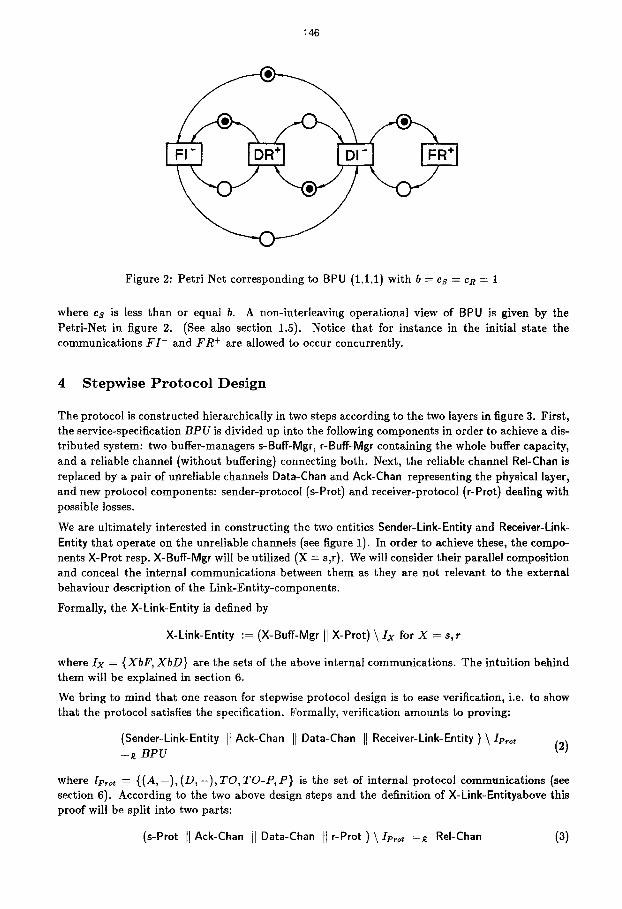
The parameters specifying the BPU are the buffer capacity b, the credit window size at the sender side cs and at the receiver side cR. Here, b limits the allocated_buffer as well as the waiting_data. cs, cR limits the credit .sender, cR limits the the credit_receiver. This leads to the following specification:
BPU(b, cs,eR) [ F I - , D R + , F R + , D I -] := ( a.h C ABp U = { F I - , D R + , F R + , D I -} A 0 ~_ allocated_buffer(h) ~_ b A 0 ~ waiting data(h) ~ b A 0 ~_ credit_sender(h) ~_ cs A 0 ~_ credit_receiver(h) ~_ cR ),
:To assist intuition a direction is attached to events corresponding to sending (=-') and receiving ("+') of data.
146
Figure 2: Petri Net corresponding to BPU (1.1.1) with b = cs = CR = 1
where c~ is less than or equal b. A non-interleaving operational view of BPU is given by the Petri-Net in figure 2. (See also section 1.5). Notice that for instance in the initial state the communications F I - and F R + are allowed to occur concurrently.
4 S t e p w i s e P r o t o c o l D e s i g n
The protocol is constructed hierarchically in two steps according to the two layers in figure 3. First, the service-specification B P U is divided up into the following components in order to achieve a dis- tributed system: two buffer-managers s-Buff-Mgr, r-Buff-Mgr containing the whole buffer capacity, and a reliable channel (without buffering) connecting both. Next, the reliable channel ReI-Chan is replaced by a pair of unreliable channels Data-Chan and Ack-Cban representing the physical layer, and new protocol components: sender-protocol (s-Prot) and receiver-protocol (r-Prot) dealing with possible losses.
We are ultimately interested in constructing the two entities Sender-Link-Entity and Receiver-Link- Entity that operate on the unreliable channels (see figure 1). In order to achieve these, the compo- nents X-Prot resp. X-Buff-Mgr will be utilized (X = s,r). We will consider their parallel composition and conceal the internal communications between them as they are not relevant to the external behaviour description of the Link-Entity-components.
Formally, the X-Link-Entity is defined by
X-Link-Entity :-- (X-Buff-Mgr I] X-Prot) \ Ix for X -- s,r
where I x = {XbF , X b D } are the sets of the above internal communications. The intuition behind them will be explained in section 6.
We bring to mind that one reason for stepwise protocol design is to ease verification, i.e. to show that the protocol satisfies the specification. Formally, verification amounts to proving:
(Sender-Link-Entity II Ack-Chan II Data-Chan H Receiver-Link-Entity ) \ Ivrot (2) =~ B P U
where Ip~o, -- {(A, - ) , (D, - ) , TO, T O - P , P } is the set of internal protocol communications (see section 6). According to the two above design steps and the definition of X-Link-Entityabove this proof will be split into two parts:
(s-Prot II Ack-Chan II Oata-Chan II r-Prot ) \ Ie,o, ---~ ReI-Chan (3)

147
f
DR FI FR DI
~ s,rvIo,, I speolfloatlon I
(BPUI L
f I
sbF s-buff - rel- -mgr 8bD= than
/
,,,,,,,,,,,,
~ s-prot ~ unrel- chan
rbF = r-buff rbD = -mgr
Figure 3: Design Strategy
and (s-Buff-Mgr It ReI-Chan II r-Buff-Mgr ) \ (Is U IR) =~ BPU (4)
The proof utilizes the fact that one can interchange the order in which parallel composition of pro- cesses 'H' and concealment of events ' \ ' are applied. The conditions which guarantuee correctness of this proceeding are subject of the so-called Modular Verification Theorem, proven in [BDF].
Notice that equation 4 in part icular involves the fact that no additional buffer capcity is created when subdividing BPU. (For the proofs see section 7).
5 First Design Step: Introducing Distribution
As mentioned in the previous section, the main feature that is added is the distribution of buffer capacity. It turns out that the component BPU can be used (with some slight modifications) to specify the local buffer managers. The reliable channel ReI-Chan basically represents the window to be realized later, preserving the buffer capacity. For details see [BDF].
6 Second Design Step: Sliding Window
In a second step we consider the underlying unreliable channels. For that reason we add new protocol components: s-Prot and r-Prot. For these protocol components we recognize the following basic functions:
1. Error detection and recovery.
2. Intercommunication with the matching local buffer manager.
3. Indication rsp. inquiry of the buffer status of the receiver link entity.
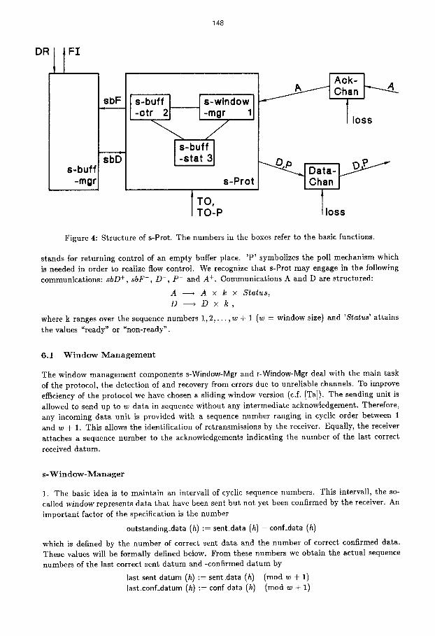
Item 2 is required as the protocol component uses the buffer of the local buffer manager, item 3 in order to realize flow control. Figure 4 illustrates the structure of the protocol component s-Prot: Here, 'A ' means acknowledgement, 'D' stands for data. When s-Prot executes 'sbD +', control over a buffer place containing one datum is passed from s-Buff-Mgr to s-Prot. Vice versa ' sbF- '
148
°R 1 I FI
sbD s-buff
-mgr
I s-buff ~ s-window] -otr 21 I-mgr 1
-... / I,-buff I
-stat 3J s-Prot
I T O ,
TO-P
Figure 4: Structure of s-Prot. The numbers in the boxes refer to the basic functions.
stands for returning control of an empty buffer place. 'P ' symbolizes the poll mechanism which is needed in order to realize flow control. We recognize that s-Prot may engage in the following communications: sbD +, sbF-, D- , P - and A +. Communications A and D are structured:
A ---4 A x k x Status,
D - - - * D x k ,
where k ranges over the sequence numbers 1, 2 , . . . , w + 1 (w = window size) and 'Status' attains
the values "ready" or "non-ready".
6.1 W i n d o w M a n a g e m e n t
The window management components s-Window-Mgr and r-Window-Mgr deal with the main task of the protocol, the detection of and recovery from errors due to unreliable channels. To improve efficiency of the protocol we have chosen a sliding window version (c.f. [Ta D. The sending unit is allowed to send up to w data in sequence without any intermediate acknowledgement. Therefore, any incoming data unit is provided with a sequence number ranging in cyclic order between 1 and w + 1. This allows the identification of retransmissions by the receiver. Equally, the receiver attaches a sequence number to the acknowledgements indicating the number of the last correct
received datum.
s- W i n d o w - M a n a g e r
1. The basic idea is to maintain an intervall of cyclic sequence numbers. This intervall, the so- called window represents data that have been sent but not yet been confirmed by the receiver. An important factor of the specification is the number
outstanding_data (h) := sent_data (h) - conf_data (h)
which is defined by the number of correct sent data and the number of correct confirmed data. These values will be formally defined below. From these numbers we obtain the actual sequence numbers of the last correct sent datum and -confirmed datum by
last sent datum (h) := sent data (h) (rood w + 1) last_conf_datum (h) := conf_data (h) (rood w + 1)
149
Notice, that ]ast_conf_datum (h) (3 1 represents the number of the first outs tanding da tum - pro- vided there are unconfirmed data. Recall that @ denotes + (mod (w + 1)). Likewise • denotes subtract ion with range 0, 1 , . . . , w.
2. We shall now look more closely at the definition of sent_data (h) and conf_data (h): If we abstract from losses and retransmission of data, a typical trace h of send events would be
D~- D ; . . . D~+ 1 D~- D ; (5)
In this case z the number of correct sent data simply is the number of D~ in h (x arbitrary), i.e. the counter D - # h , cf. section 1. The t rea tment of retransmission, however, may lead to more complicated traces like
D~- D~ D ; D~- D ; D ; D ; D~ (6)
where retransmissions are underl ined for i l lustration as they intuitively do not change the number of correct sent data. Below we list this number for all prefixes of the trace 6 yielding
0 1 1 2 2 2 3 3 3 (7)
the initial zero referring to the empty trace. For an arbi trary trace the number of correct sent data can be computed by the following rule:
sent_data (e) = 0 k + l i f a = D ~ - ¢ t (8)
sent_data (h) = k => sent_data (ha) = k else
3. We now discuss the receipt of acknowledgements. Omit t ing multiple confirmations a typical trace of acknowledgements would be (for, say w _> 5)
At + A + A + A + (9)
In this s i tuat ion the receiver confirmed the frames D~, D ; and D~ with one acknowledgement A +. The increment 2 --~ 5 of sequence numbers indicates that all frames with numbers 3, 4, and 5 have been correctly received. This fact is captured by the following definition of conf_data (h):
conf_data (e) = 0 k + ( l @ k ) i f a = A + (10)
conf_data (h) = k ::> conf_data ( h a ) = k else
The last definition takes into consideration the fact that at most the last correct received acknowl- edgement may be received several times (iff I @ k = 0), as the channels preserve the order of data: As an example we have for w -- 2
conf_data (A1 + A2 + A + A +) = 4
Notice that a retransmission of, say A +, follows immediately the first confirmation A +.
4. For the specification of the window-management it will be impor tant to know whether the last occurence of a D - event refers to the first t ransmission of a datum. This fact can be decided by looking at the increment of the function sent data (h). The increment Asent_data (h) is defined to be zero for empty trace and
Asent_data (ha) := sent_data (ha) - sent_data (h)
3D~- stands for (D-,i)
150
We define the last occurence of D~- in a trace h to be a 'fresh' one , if the increment is positive:
freshD-(h ) := Asent_data (hiD-) > 0
E.g. for h = h ~ D[- where hi =D[- D~ D ; D ; A + D~ A + D ;
we have (assuming w = 2) sent_data (hiD-) - -4 and sent_data (hi [D- ) -~ 3 , hence fresho-(h ). Likewise, we define freShA+(h ) .
5. We are now prepared to specify the functions of s-Window-Mgr: the sender is allowed to send up to w data in advance without any intermediate confirmation. Trivially it may only expect confirmation for data that have previously been sent. Hence we require
0 <_ outstanding_data (h) < w (11)
When the sender forwards a new datum it increments the respective sequence number by 1 (rood w + 1). Say, the number of the last fresh datum is k, then the number of the previous correct sent datum must be k @ 1. Furthermore, the very first frame number is 1. These facts are expressed by the formulas
last (hiD-) = k A fresh D-(h) =~ last_sent_datum (head (hiD-)) = k @ 1, (12) first (hiD-) = 1
6. The following three predicates 13, 14, 15 describe the conversation modus between s-Window-Mgr and r-Window-Mgr. Here, the master-slave modus is employed, the sender being the master. A timer is used to initiate the retransmission of all outstanding data after some period of time.
last (h) = TO ~ (outstanding_data (h) > 0 A last2 (h) ¢ TO) (13)
This gives a necessary condition for a timeout. When a timeout has occured we require that the sender retransmit all outstanding data in one go: by this we simply mean that if the last event was a retransmission with number k, then the last but one event is the retransmission k (9 1 etc. In case that k represents the first outstanding datum (= last_conf_datum (h)~ 1), the last but one event is the triggering timeout. More precisely,
last(h) =D~- A -~fresh D-(h) A last conf_datum (h) , 1 # k last2 (h) = D;e 1 (14)
and last (h) = D ; A =fresh o - ( h ) A last_conf_datum (h) @ 1 = k
=~ last~ (h) = TO (15)
7. Summarizing, we now define the specification of s-Window-Mgr to be
s-Window-Mgr(w) [D-,A+,TO] --DI {ct.h C_ {D-,A+,TO} A HSwM(h))
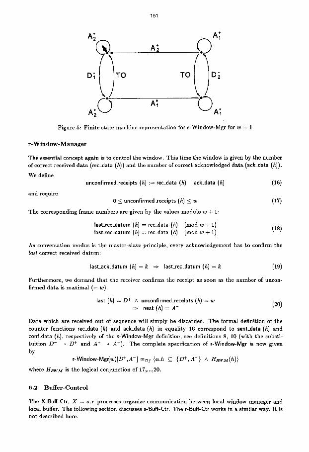
where HswM(h) is the logical conjunction of requirements 11, ..., 15. By the Initial Communication Theorem 1.2 we can derive a process P for this specification. For window-size w = 1 it is depicted in figure 5.
TO D~ TO
151
A;
Figure 5: Fini te state machine representation for s-Window-Mgr for w = 1
r - W i n d o w - M a n a g e r
The essential concept again is to control the window. This t ime the window is given by the number of correct received data (rec_data (h)) and the number of correct acknowledged data (ack_data (h)).
We define unconfirmed_receipts (h) := rec_data (h) - ack_data (h) (16)
and require 0 < unconfirmed _receipts (h) <_ w (17)
The corresponding frame numbers are given by the values modulo w + 1:
last_rec_datum (h) = rec_data (h) ( n o d w + 1) (18) last_rec_datum (h) = rec_data (h) (rood w + 1)
As conversation modus is the master-slave principle, every acknowledgement has to confirm the last correct received datum:
last_ack_datum (h) = k =~ last_rec_datum (It) = k (19)
Furthermore, we demand that the receiver confirms the receipt as soon as the number of uncon- firmed data is maximal (= w).
last (h) = / 9 + A unconfirmed_receipts (h) = w (20) =~ next (h) = A-
Data which are received out of sequence will simply be discarded. The formal definition of the counter functions rec_data (h) and ack_data (h) in equality 16 correspond to sent_data (h) and conf_data (h), respectively of the s-Window-Mgr definition, see definitions 8, 10 (with the substi- tui t ion D - --* D + and A + --+ A-) . The complete specification of r-Window-Mgr is now given by
r-Window-Mgt(w)[D+,A -] =Dr (vL.h C_ {D+,A -} A HRwM(h))
where HRWM is the logical conjunct ion of 17 , . ,20 .
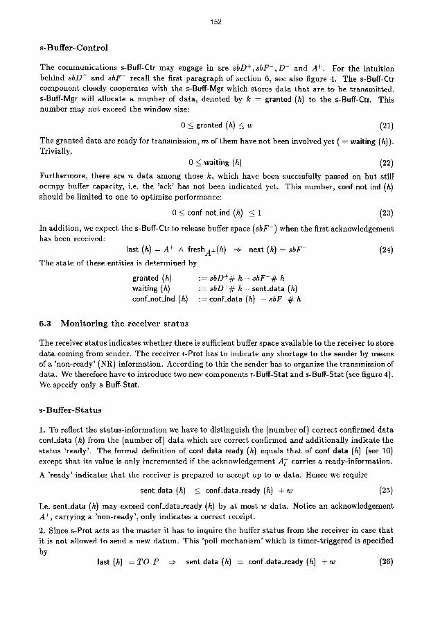
6.2 B u f f e r - C o n t r o l
The X-Buff-Ctr, X = s, r processes organize communicat ion between local window manager and local buffer. The following section discusses s-Buff-Ctr. The r-Buff-Ctr works in a similar way. It is not described here.
152
s -Buf fe r - C o n t r o l
The communicat ions s-Buff-Ctr may engage in are ~bD+,sbF- ,D - and A +. For the intuit ion behind sbD + and sbF- recall the first paragraph of section 6, see also figure 4. The s-Buff-err component closely cooperates with the s-Buff-Mgr which stores data that are to be transmit ted. s-Buff-Mgr will allocate a number of data, denoted by k = granted (h) to the s-Buff-Ctr. This number may not exceed the window size:
0 < granted (h) _< w (21)
The granted data are ready for transmission, m of them have not been involved yet ( = waiting (h)). Trivially,
0 < waiting (h) (22)
Furthermore, there are n data among those k, which have been succesfully passed on but still occupy buffer capacity, i.e. the 'ack' has not been indicated yet. This number , conf_not ind (h) should be limited to one to optimize performance:
0 < conf not_ind (h) < 1 (23)
In addition, we expect the s-Buff-Ctr to release buffer space (sbF-) when the first acknowledgement has been received:
last (h) = A + A freshA+(h ) =~ next (h) = sbF- (24)
The state of these entities is determined by
granted (h) := 8bD+# h - s b F - # h waiting (h) := 8bD+# h - sent_data (h) conf_not_ind (h) := conf_data (h) - ~bF-# h
6.3 M o n i t o r i n g t h e r e c e i v e r s t a t u s
The receiver status indicates whether there is sufficient buffer space available to the receiver to store data coming from sender. The receiver r-Prot has to indicate any shortage to the sender by means of a 'non-ready ' (NR) information. According to this the sender has to organize the transmission of data. We therefore have to introduce two new components r-Buff-Star and s-Buff-Star (see figure 4). We specify only s-Buff-Star.
s - B u f f e r - S t a t u s
1. To reflect the s tatus- information we have to distinguish the (number of) correct confirmed data conf_data (h) from the (number of) data which are correct confirmed and additionally indicate the status ' ready' . The formal definition of conf data ready (h) equals that of conf data (h) (see 10) except that its value is only incremented if the acknowledgement A + carries a ready-information.
A ' ready' indicates that the receiver is prepared to accept up to w data. Hence we require
sent_data (h) < conf_data_ready (h) + w (25)
I.e. sent_data (h) may exceed conf_data_ready (h) by at most w data. Notice an acknowledgement A +, carrying a 'non-ready ' , only indicates a correct receipt.
2. Since s-Prot acts as the master it has to inquire the buffer status from the receiver in case that it is not allowed to send a new datum. This 'poll mechanism' which is timer-triggered is specified by
last (h) = TO_P =~ sent_data (h) = conf_data_ready (h) + w (26)
153
0 <_ TO_P#h - P - # h <_ 1 (27)
last (h) = TO_P ~ next (h) = P - (28)
where TO_P denotes a timer, and P - is a 'send poll' event. Notice, that we demand a 'send poll' to occur immediately after a time-out (cf. 28). Finally, the alphabet for this component is A~Bs = {D- , A +, P - , TO_P}.
7 Veri f icat ion
We claim that the protocol, as described in sections 4, 5, 6, is semantically identical with the service specification (section 3) . This is described by means of equality 2. Informally, the statement says that the protocol components manage with losses in the channels 4 . Of course, this can be true only if the channels do not loose data infinitely often in sequence. Hence our proof will be based on the following fairness property
(FP) ~ 3heA*eh~," V ne N 3h, e {loss, x-}* : Hvh~,[h.h,/h] (29)
where Hvh~, is the predicate describing either of the channels and Avhan. = ( l o s s , x - , x +} with x e {D, A}.
The proof of the claim is divided up into two parts along the lines of the protocol design (see figure 3): We first establish equaltity 4. The proof can be performed on a logical level by means of the Hiding Theorem 1.4, it is given in [BDF]. We notice that the proof holds for arbitrary parameter values b, cs, CR.
To establish equality 3 we make use of the fact that equality based on observational equivalence implies equality based on readiness equivalence (if there are no cycles of v-actions), cf. section 1.3. In order to show observational equivalence, all relevant specifications of subeomponents are trans- formed into processes, and their parallel composition is computed. Then equality 3 w.r.t, obser- vational equivalence is proved by means of a CCS-Tool ([Fr]). Due to the large number of states we restricted ourselves to window-size w = 1. For details see [DB]. The reason for showing ob- servational euqivalence rather than readiness equivalence is: it is by far to tedious to ensure the 'same-liveness-condition' of the Hiding-Theorem 1.4.
8 C o n c l u s i o n
The protocol was developed in a top-down manner: we started with the service specification describing the protocol seen as a single unit from a network-layers view. Next, we considered the distribution aspect of the protocol which is made up by two local buffers connected by a channel.
In the first place we assumed this (logical) channel to be reliable, and proved the correctness of the refinement. In a second step we dropped this assumption and designed two protocol components coping with leaky physical channels. Again, this can be proved to be consistent with the service description.
Concerning specification we first identified the manifold (protocol-)functions. For description we utilized formulas of trace-logic as defined by [O12]. They provide for a compact representation of characteristic protocol invariants, their length being independent of the window-size. Compo- sitionality of the semantics allowed for the discussion of one protocol function at a time. This
4The specification of a finite channel with non-deterministic losses is standard. It is not presented here.
154
simplifies the design a lot, as one has to concentrate on one aspect only. Furthermore, composi- tionality supports reuse of components. Verification can be done using appropriate proof rules (for arbitrary parameters of the specification) and algebraic methods.
Regarding more complex structures it would be valuable to have the notion of states as part of the logic. (We introduced states implicitly only.) This will be one subject for further studies.
References
[BK1]
[BDF]
[DDM]
[DHKR]
[DB]
[fr]
[ISO]
ILS]
[Mi]
[o111
[o121
[O13]
[o14] [Ta] [Zw]
Bergstra, J.A., Klop,J.W.: Algebra of communicating processes, Report CS-R8421, Cen- trum voor Wiskunde en Informatica, Amsterdam, 1984
Bretschneider,M.; Duque Anton,M.; Fink,B.: Constructing and Verifying Protocols using TCSP, Proc. IFIP TC6 on Protocol Specification, Testing and Verification, Atlantic City, June 1988, Aggarwal,S. and Sabnani,K. (ed), North-Holland Publ. Comp.
Degano,P.; DeNicola,R.;Montanari,U.: A new operational semantics for CCs based on condition/event systems, Nota Interna B4-42, Dept. of Computer Science, Univ. Pisa, 1986
Dnke,R.; Hayes,L; King,P.; Rose,G.: Protocol Specification and Verification Using Z, Proc. IFIP TC6 on Protocol Specification, Testing and Verification, Atlantic City, June 1988, Aggarwal,S. and Sabnani,K. (ed), North-Holland Publ. Comp.
Duqne Ant6n, M., Bretschneider, M.: Modulare Spezifikation und Verifikation yon Kom- munikationsprotokollen, internal report, 1987
Fritschi, K.-D.: Automatische Protokollverifikation in CCS, Diplomarbeit, TU Karlsruhe, Karlsruhe 1987
ISO: Information Processing Systems - Open System Interconnection, Basic Reference Model, ISO 7498, 1983
Lam,S.S, Shankar, A.U.: Protocol verification via Projections, IEEE Trans.Softw.Eng. Vol SE-10,4,July,1984
Milner,R.: A calculus of communicating systems, LNCS 92, Springer,1980
Olderog, E.-R.: Process Theory: Semantics, Specification and Verification, in: de Bakker, J.W. et. al. (Ed.): Current trends in concurrency, LNCS 229, Springer, 1986
Olderog, E.-R.: Nets, terms and formulas: Three views of concurrent processes, REX School/Workshop on Linear Time, Branching Time and Partial Order in Logics and Models for Concurrency, Nordwijkerhout, the Netherlands, May 30 - June 3, 1988
Olderog, E.-R.: Operational Petri Net Semantics for CCSP, in: Advances in Petri-Nets 1987, G.Rozenberg (Ed.), Springer LNCS 266, 1987
Olderog, E.-R.: private communication
Tanenbaum, A.: Computer Networks, Prentice Hall, 1981
Zwiers, J.:Compositionality, Concurrency and Partial Correctness, Doctoral Thesis Uni- versity of Eindhoven, 1988.