forward tracking; - iccubicc.ub.edu/congress/ilc-2009/ilc-bcn09/may7/marcelvos.pdf · why is...
TRANSCRIPT
[email protected], May 7th 2009
Forward Tracking; physics case, challenges and design
Forward Tracking; physics case, challenges and detector design
Terceras jornadas sobre la participación
Española en los futuros colisionadores
Lineales de particulas
U. Barcelona
May 6, 2009
Marcel Vos (IFIC – U. Valencia/CSIC)
Thanks to the DEPFET, SiLC and the Spanish community involved in future accelerators
[email protected], May 7th 2009
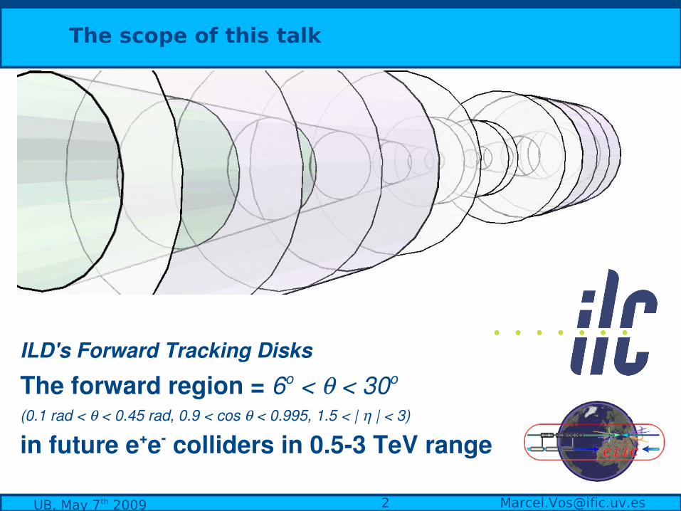
The scope of this talk
ILD's Forward Tracking Disks
The forward region = 6o < < 30o (0.1 rad < < 0.45 rad, 0.9 < cos < 0.995, 1.5 < | | < 3)
in future e+e colliders in 0.53 TeV range

[email protected], May 7th 2009
The physics case
Why is forward tracking performance important?
There is a series of very relevant physics processes where final state particles are predominantly emitted at small polar angleMostly electrons, but also muons, t, b and cjets

[email protected], May 7th 2009
From LEP-I to the ILC (to CLIC)
e+e- + -
with(----)/without(- - -) ISR
LEP-I, 91 GeV ILC 500 GeV
1 TeV 3 TeV
Determine the relevance of the forward region in several key processes for a number of scenarios increasing center-of-mass energy
PX30
: Probability that final state
product X is emitted at a polar angle 5 < < 30o
No ISR
Total x-sec
[email protected], May 7th 2009
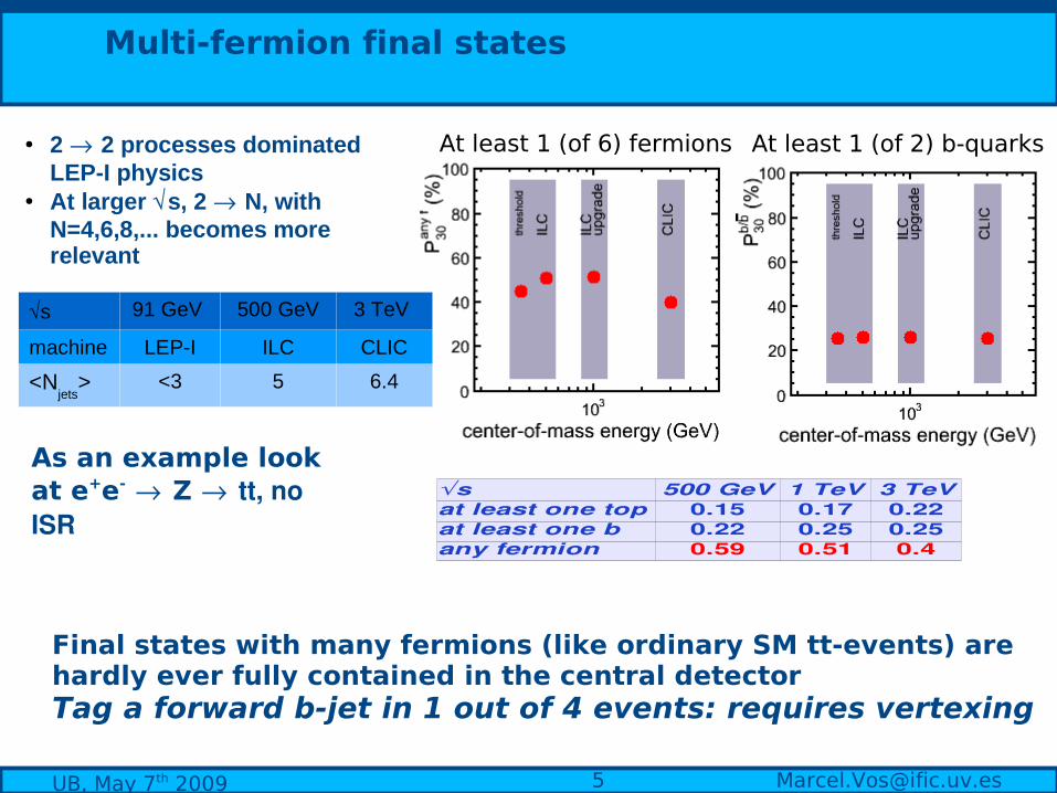
Multi-fermion final states
Final states with many fermions (like ordinary SM tt-events) are hardly ever fully contained in the central detectorTag a forward b-jet in 1 out of 4 events: requires vertexing
at least one top 0.15 0.17 0.22at least one b 0.22 0.25 0.25any fermion 0.59 0.51 0.4
s 500 GeV 1 TeV 3 TeV
● 2 2 processes dominated LEP-I physics
● At larger s, 2 N, with N=4,6,8,... becomes more relevant
At least 1 (of 6) fermions At least 1 (of 2) b-quarks
s 91 GeV 500 GeV 3 TeV
machine LEP-I ILC CLIC
<Njets
> <3 5 6.4
As an example look at e+e- Z tt, no ISR
[email protected], May 7th 2009
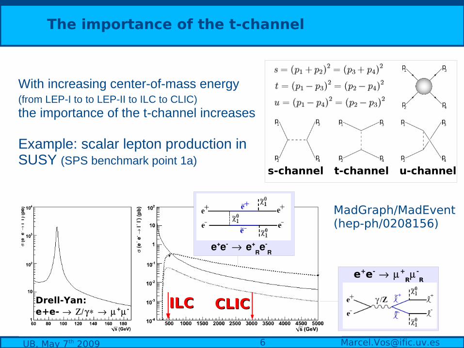
With increasing center-of-mass energy (from LEP-I to to LEP-II to ILC to CLIC) the importance of the t-channel increases
Example: scalar lepton production in SUSY (SPS benchmark point 1a)
The importance of the t-channel
Drell-Yan: e+e- + -
e+e e+Re
R
ILCILC CLICCLIC
s-channel t-channel u-channel
e+e- +R -
R
MadGraph/MadEvent (hep-ph/0208156)
[email protected], May 7th 2009
The importance of the t-channel
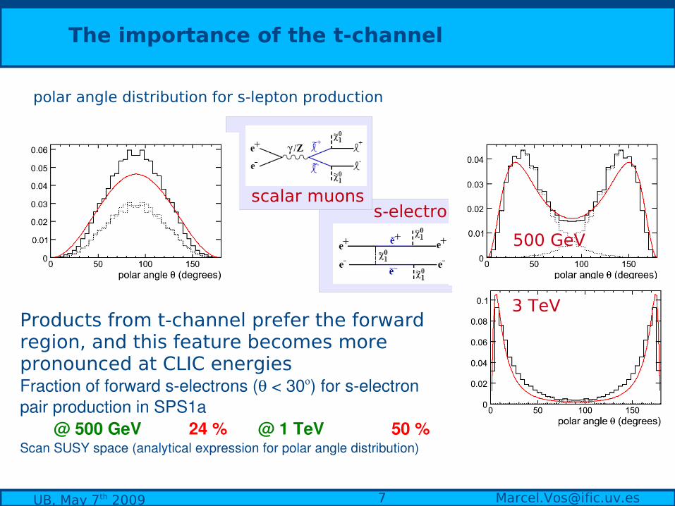
polar angle distribution for s-lepton production
Products from t-channel prefer the forward region, and this feature becomes more pronounced at CLIC energiesFraction of forward selectrons ( < 30) for selectron pair production in SPS1a
@ 500 GeV 24 % @ 1 TeV 50 % Scan SUSY space (analytical expression for polar angle distribution)
scalar muonss-electrons
500 GeV
3 TeV
[email protected], May 7th 2009
t-channel
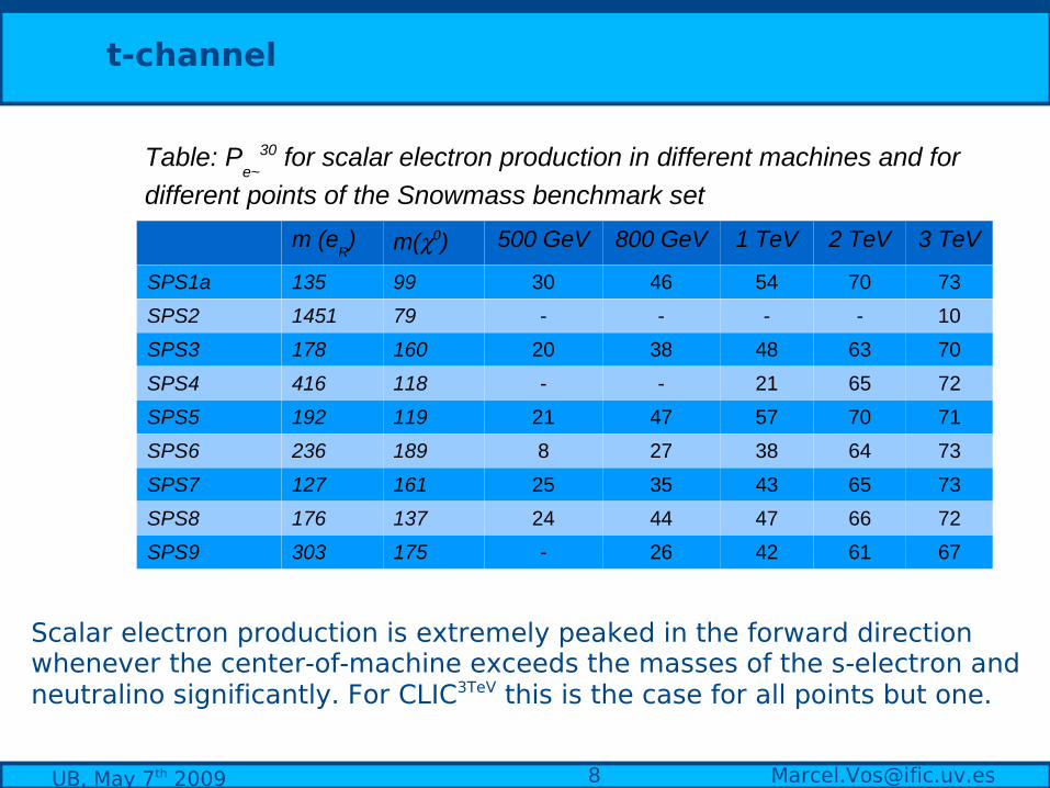
Table: Pe~
30 for scalar electron production in different machines and for
different points of the Snowmass benchmark set
m (eR) m(0) 500 GeV 800 GeV 1 TeV 2 TeV 3 TeV
SPS1a 135 99 30 46 54 70 73
SPS2 1451 79 - - - - 10
SPS3 178 160 20 38 48 63 70
SPS4 416 118 - - 21 65 72
SPS5 192 119 21 47 57 70 71
SPS6 236 189 8 27 38 64 73
SPS7 127 161 25 35 43 65 73
SPS8 176 137 24 44 47 66 72
SPS9 303 175 - 26 42 61 67
Scalar electron production is extremely peaked in the forward direction whenever the center-of-machine exceeds the masses of the s-electron and neutralino significantly. For CLIC3TeV this is the case for all points but one.
[email protected], May 7th 2009
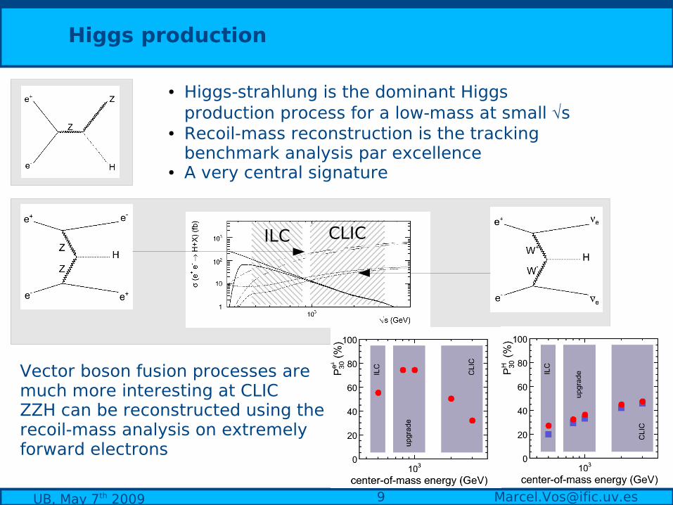
Higgs production
● Higgs-strahlung is the dominant Higgs production process for a low-mass at small s
● Recoil-mass reconstruction is the tracking benchmark analysis par excellence
● A very central signature
CLICILC
Vector boson fusion processes are much more interesting at CLICZZH can be reconstructed using the recoil-mass analysis on extremely forward electrons

[email protected], May 7th 2009
Di-boson production
The polar angle distribution of electrons is extremely peaked in forward direction
The last example: di-boson production.

[email protected], May 7th 2009
Forward tracking physics case
Little guidance for forward detector design from standard benchmark reactions (cos < 0.95)
Together with many other analyses and channels that we didn't discuss:
● AFB
in the bb and cc system● Degenerate staus and neutralino● center-of-mass energy determination using
eventsThese examples make the physics case for orward tracking:
At a high-energy e+e- collider several potentially very interesting physics analyses require excellent tracking and vertexing performance. These arguments become more urgent as the center-of-mass energy increases. Precise electron reconstruction is of particular importance.
[email protected], May 7th 2009
Why is forward tracking challenging?
The material!Hermetic coverageSignificant background at smallest radii The unfavorable orientation of the magnetic fieldAbundant low momentum tracks – pattern recognition

[email protected], May 7th 2009
Incoherent e+e pair production off beamstrahlung photons produces a very large number of electrons and positrons each BX. The large majority is soft and/or emitted at low angle and are trapped in the “accumulation zone”
LDC forward tracker:
e+beamstrahlung γ
beamstrahlung γ
e+
e-
beamstrahlung γ
virtual γ
e+
e-
e
e+
e-
e-
virtual γ
virtual γ
Breit-Wheeler Bethe-Heitler Landau-Lifshitz
Environment: background level
GuineaPig LowP focus
100 MeV
0.1 rad
detector
Z (m)
R (m)
[email protected], May 7th 2009
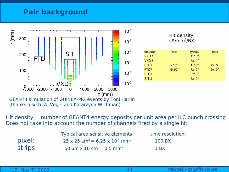
Pair background
Hit density = number of GEANT4 energy deposits per unit area per ILC bunch crossing Does not take into account the number of channels fired by a single hit
Typical area sensitive elements time resolution:
pixel: 25 x 25 m2 = 6.25 x 10⁻⁴ mm2 100 BX
strips: 50 m x 10 cm = 0.5 mm2 1 BX
Hit density (#/mm2/BX)
VXD
FTDSIT detector max
VXD 1VXD 6FTD1FTD7SIT 1SIT 2
min typical4x102
3x10⁴
<105 1x10⁴ 2x10³
5x10⁶ 7x10⁶ 9x10⁶
3x10⁵
3x10⁶
GEANT4 simulation of GUINEA-PIG events by Toni Harlin (thanks also to A. Vogel and Katarzyna Wichman)
[email protected], May 7th 2009
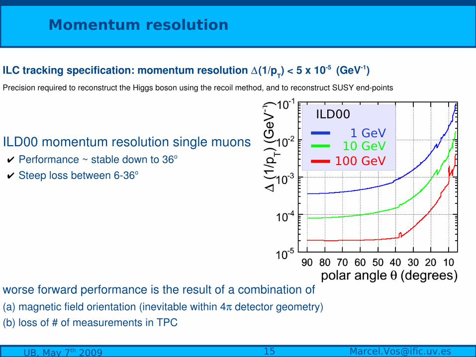
Momentum resolution
100 GeV 10 GeV 1 GeV
ILD00
ILC tracking specification: momentum resolution (1/pT) < 5 x 10⁵ (GeV1)
Precision required to reconstruct the Higgs boson using the recoil method, and to reconstruct SUSY endpoints
ILD00 momentum resolution single muons✔ Performance ~ stable down to 36o ✔ Steep loss between 636o
worse forward performance is the result of a combination of (a) magnetic field orientation (inevitable within 4 detector geometry)(b) loss of # of measurements in TPC
[email protected], May 7th 2009
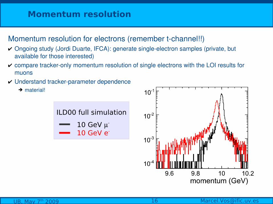
Momentum resolution
Momentum resolution for electrons (remember tchannel!!)✔ Ongoing study (Jordi Duarte, IFCA): generate singleelectron samples (private, but
available for those interested)✔ compare trackeronly momentum resolution of single electrons with the LOI results for
muons ✔ Understand trackerparameter dependence
➔ material!
10 GeV e- 10 GeV -
ILD00 full simulation
[email protected], May 7th 2009
100 GeV 10 GeV 1 GeV
ILD00
a=5,b=10
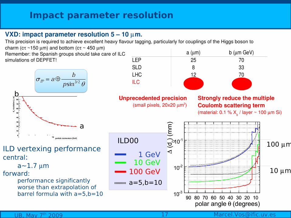
Impact parameter resolution
LEP 25 70SLD 8 33LHC 12 70ILC 5 10
a (m) b (m GeV)
Unprecedented precision(small pixels, 20x20 m2)
Strongly reduce the multiple Coulomb scattering term(material: 0.1 % X
0 / layer ~ 100 m Si)
b
a
100 m
10 m
ILD vertexing performancecentral:
a~1.7 mforward:
performance significantly worse than extrapolation of barrel formula with a=5,b=10
VXD: impact parameter resolution 5 – 10 m. This precision is required to achieve excellent heavy flavour tagging, particularly for couplings of the Higgs boson to charm (c ~150 m) and bottom (c ~ 450 m)Remember: the Spanish groups should take care of ILCsimulations of DEPFET!

[email protected], May 7th 2009
Pattern recognition
Clearly, 6-15 degrees is weakest region in ILD in terms of number of measurements. And remember:
● non-negligible pair background● First disks close to interaction point (jets!)● Abundant low-momentum tracks (loopers)
FTD1 9 37 1.1 12FTD2 5 27 0.6 10FTD3 8 36 0.4 10FTD4 6 29 0.3 9FTD5 5 25 0.3 10FTD6 4 23 0.2 5FTD7 3 28 0.2 4
#hits /disk #hits /petaldisk avg. peak avg. peak
Ongoing study (Carmen Iglesias) Evaluate hit densities in tt events per disk and per petal (subdividing disks in 8,20 or 16 single-wafer segments)
● Average #hits/disk falls by a factor 3 due to reduced angular coverage of outermost disks
● Average #hits/petal falls even faster (outermost disks divided in 16 segments)
It is important to evaluate the hit density locally (jets)
● A significant probability to receive several hits/petal remains even in the outermost disk
[email protected], May 7th 2009
Pattern recognition - tools
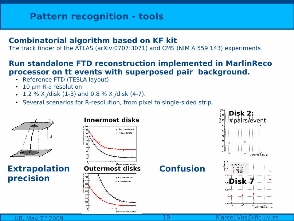
Combinatorial algorithm based on KF kitThe track finder of the ATLAS (arXiv:0707:3071) and CMS (NIM A 559 143) experiments
Run standalone FTD reconstruction implemented in MarlinReco processor on tt events with superposed pair background.
● Reference FTD (TESLA layout) ● 10 m R- resolution● 1.2 % X
0/disk (1-3) and 0.8 % X
0/disk (4-7).
● Several scenarios for R-resolution, from pixel to single-sided strip.
Innermost disks
Outermost disksExtrapolation precision Disk 7
Disk 2:#pairs/event
Confusion
[email protected], May 7th 2009
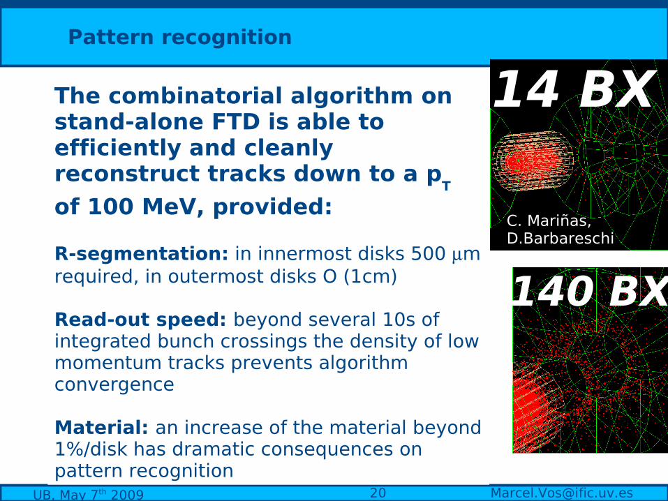
Pattern recognition
The combinatorial algorithm on stand-alone FTD is able to efficiently and cleanly reconstruct tracks down to a p
T
of 100 MeV, provided:
R-segmentation: in innermost disks 500 m required, in outermost disks O (1cm)
Read-out speed: beyond several 10s of integrated bunch crossings the density of low momentum tracks prevents algorithm convergence
Material: an increase of the material beyond 1%/disk has dramatic consequences on pattern recognition
14 BX
140 BX
C. Mariñas, D.Barbareschi
[email protected], May 7th 2009
Towards an engineered design
Calibration/alignmentMechanical supportServices

[email protected], May 7th 2009
Towards an FTD design
➔Micro-strip module guidelines:➘ ROC on sensor
➘ ROC thinned to 50-100 um➘ 6” wafers (approx 10 cm x 10 cm sensors)➘ 150 µm thickness
➘ Two sensor layers per disk.
David Moya, IFCA
[email protected], May 7th 2009
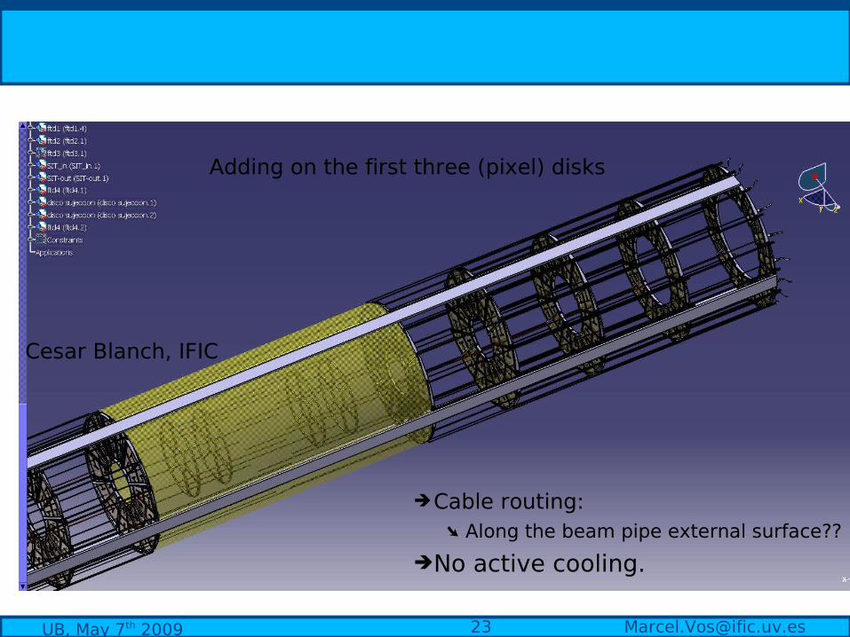
➔Cable routing:➘ Along the beam pipe external surface??
➔No active cooling.
Adding on the first three (pixel) disks
Cesar Blanch, IFIC

[email protected], May 7th 2009
Conclusions
Interest of the forward region:in several interesting physics cases the final state products have a strong preference for the forward region
Specific challenges: momentum resolution under unfavorable field orientationimpact parameter measurement for very forward tracksnon-negligible background level (read-out speed)standalone pattern recognition (background, low p tracks)minimal distortion of particles/global performance
Requirements:granularity @ reasonable speed staying within the power budget
Laser alignment:the only “many-layer” silicon system in ILD
Towards a design:engineering studies of FTD
More information on http://ific.uv.es/~vos/ilc

[email protected], May 7th 2009
REFERENCESA. Savoy Navarro et al. (the SiLC collaboration), PRC review, DESY, 2008A. Savoy Navarro et al. (the SiLC collaboration), ILC tracking review, Beijing 2007 The challenges of forward tracking, invited talk, IEEE NSS&MIC, Dresden, Germany, 2008Forward tracking, TILC08 (ACFA/EDG) Sendai, Japan, 2008 The silicon tracker elements, ILD meeting, Sendai, Japan, 2008Forward Tracking, SiD meeting, Oxford, UK, 2008The silicon tracker, First ILD workshop, Desy Zeuthen, Germany, 2008 Tracking and alignment at the ILC, invited talk, 2nd alignment workshop for the LHC, CERN,
Ginebra, Switzerland, 2007 Tracking at the ILC,invited talk, 8th International Conference on Large Scale Applications and
Radiation Hardness of Semiconductor Detectors, published Nucl. Instr. Meth.,Overview of SiLC simulation, Linear Collider Workshop (LCWS07), DESY (Germany), 2007,
arXiv:0801.4509The SiLC simulation task force, ILC software workshop, Orsay, France, 2007The SiLC simulation task force, Tracking review, "the SiLC collaboration",, Beijing, China, 2007

[email protected], May 7th 2009
P = 1 GeV
P = 10 GeV
P = 100 GeV
Transverse momentum resolution versus polar angle Measured on three single-muon samples with fixed |p|
LiCToy on ILD00 (full KF fit), M. Valentan, HEPHY Vienna
FullLDCTracking on ILD00 (Mokka/MarlinReco) Vos/Duarte/Iglesias
CMS KF Track Fit on standalone FTD Vos/Duarte/Iglesias
[email protected], May 7th 2009
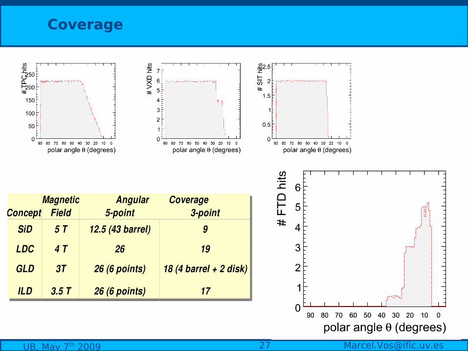
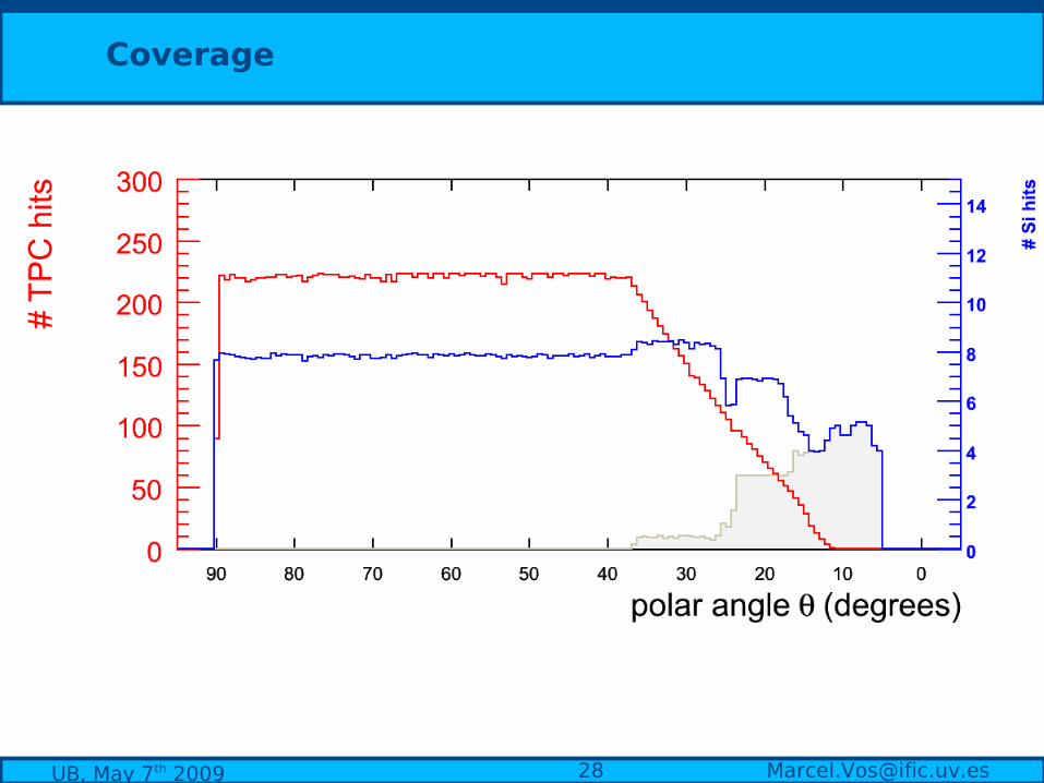
Coverage
Magnetic Angular Coverage Concept Field 5point 3point
SiD 5 T 12.5 (43 barrel) 9
LDC 4 T 26 19
GLD 3T 26 (6 points) 18 (4 barrel + 2 disk)
ILD 3.5 T 26 (6 points) 17
[email protected], May 7th 2009
P = 1 GeV
P = 10 GeV
P = 100 GeV
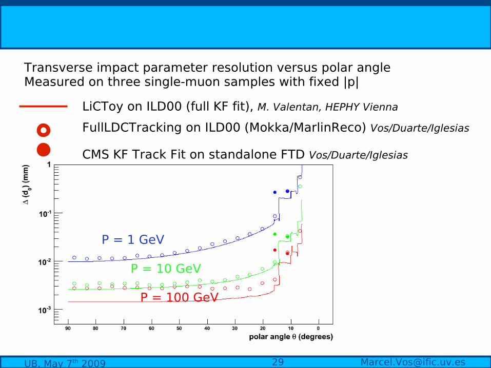
Transverse impact parameter resolution versus polar angle Measured on three single-muon samples with fixed |p|
LiCToy on ILD00 (full KF fit), M. Valentan, HEPHY Vienna
FullLDCTracking on ILD00 (Mokka/MarlinReco) Vos/Duarte/Iglesias
CMS KF Track Fit on standalone FTD Vos/Duarte/Iglesias

[email protected], May 7th 2009
Silicon for Large Colliders
Strong Spanish participation in DEPFET IFIC (since 2005)USC, UB, URL, CNM (since 2008)
IFIC, IFCA, UB, CNM, USC one EUDET member, several associates
CALICECIEMAT Madrid
BarcelonaU. R. L.U. B.CNM-IMB
IFCA USC
IFIC
CIEMAT
Coordinador ILC-España: A. Ruiz
Forward Tracker
Coordinated effort (led by A. Ruiz): regular meetings funding/projects R&D interests the forward tracker
Coordinated ILC effort in Spain