forwards suppl 1 to isi relief request 95-030,consisting
TRANSCRIPT

. .. . . . . . _
.
-
: e:lorida-Power1
CORPORATION
' EInfam'.
:s
I
February 16, 1996 '.-
3FC296-07jU. S. tiaclear Regulatory CommissionAttn: Document Control DeskWashington, D.C. 20555
Subject:- Ittservice Inspection Program (ISI) Supplement 1 to Relief Request 95-030
References: A. FP'; to NRC lett9r, 3F0995-03, dated September 22, 1995.B. NRC to FPC letter, ""1196-18, dated January 31, 1996;
h tDear Sir:-
Pursuant to 10 CFR 50.55a(g)(5), ! sorida Power Corporation (FPC) is submitting theattached ~ Relief Request 95-030, Supplement 1. The supplemented information consists ofa revision to the Code of Reference previously provided to reflect the correct Code. Thecorrect Code is the ASME Boiler and Pressure Vessel Code, Section XI,1983 Edition throughSummer 1983 Addenda. Additionally, FPC has revised the " Basis" section of the relief
- request to incorporate additional data germane to your Request for Additional Information1 (RAI), Reference B. FPC is also providing FPC responses to the RAI and Structural- Integrity Report SIR-96-016 (Attachment 1); and Structural Integrity Report SIR-95-135,
" Flaw Acceptance Handbook for Crystal River Unit 3 Reactor Pressure Vessel and Nozzle Weld' Inspections" (Attachment 2).
m
FPC has discussed the chrges provided in Relief Request 95-030, Supplement 1 and ourresponse to the RAI with our NRC Project Manager and your contractor, INEL. FPC believesthat Supplement I to the . subject relief request and FPC responses to the questions in theRAI provide a sound basis for the approval of Relief Request 95-030.
_
_
-
230034;
-, p
,3,
, .
ORVNAL RWER ENERGY OOMPt.EX e 15700 W. Paww Une Sheet e Crystalibw e Flodde 34425470s e 952| 7964486
9602230159 960216 A Hor 8d= arospens carnpeny
PDR ADOCK 05000302G PDR
. _ _ . . _ . . . . _-. ___ ._

-- _ _ _ _ _ _ _ _ _ _ _ _ _ _ _ _ _ _ _ _ _ _ _ - _ .
.
U. S. Nuclear Regulatory Commission3F0296-07Page 2
FFC would appreciate your prompt review of that information, in order to implement therequest during our refueling outage scheduled to start February 29, 1996.
. Sincerely,,
G. L. oldtVice PresidentNuclear Production
GLB/LVC
Attachmentsxc: Regional Administrator, Region 11
Senior Resident InspectorNRR Project ManagerMichael T. Anderson - INEL Research Center
L

- __ _______ __
U. S. Nuclear Regulatory Commission3F0296-07Page 3
FLORIDA POWER CORPORATIONINSERVICE INSPECTION
RELIEF REQUEST # 95-030 (SUPPLEMENT 1
CRYSTAL RIVER UNIT 3
REFERENCE CODE: ASME Boiler and Pressure Vessel Code, Section XI,1983 Edition throughSummer 1983 Addenda
I. COMPONENT FOR WHICH RELIEF IS REQUESTED:
(a) Name and Identification Number:
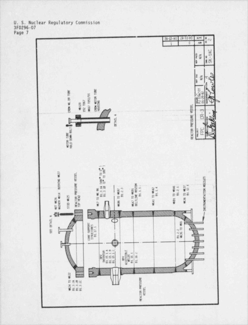
Reactor Vessel Transition Piece to Bottom Head Weld ISI Exam Number Bl.2.2 (seeattached sketch)
( (b) Function:Houses Core and Naintains Core Geometry
(c) ASME Section III Code Class:
Class I
(d) Category:
Category B-A, Pressure Retaining Welds in Reactor Vessel
II. REQUIREMENT FROM WHICH RELIEF IS REQUESTED:
ASME Boiler and Pressure Vessel Code, Section XI, Table IWB-2500-1 Item L.21,Circumferential Head Weld. Volumetric examination of this weld requires theexamination of its entire accessible length without allowance for restrictions.
III. BASIS FOR REQUESTING RELIEF:
The subject weld is the reactor vessel transition-piece-to-bottom-head weld. Thisweld is located below the beltline region and is not subject to the majority of theneutron flux escaping from the core. An evaluation of neutron embrittlement as apotential damage mechanism and other potential damage mechanisms associated withthis weld is included in the attached response to Question No. 2A of Reference B(see Attachment 1) and Attachment 2. The evaluation concludes that service-induceddegradation of the transition-piece-to-bottom-head weld as a result of corrosion,fatigue, nuclear, or thermal embrittlement mechanisms is extremely unlikely.
The weld has been visually and ultrasonically inspected once during preserviceinspection (essentially 100% coverage). The volumetric examination method utilizedduring the pre-service inspection was Manual Contact Ultrasonic. During thisexamination the weld received a 360 degree scan with the exception of those areaswhere physical interference prevented examination with the manual transducer. A
review of the data sheets for this examination revealed that there were noreportable or recordable indications detected.
_ _ _ - -

U. S. Nuclear Regulatory Commission3F0296-07Page 4
BASIS FOR REQUESTING RELIEF (Continued)
During Refueling Outage 5 (May 1985), the weld was partially inspected,
(approximately 5%). This inspection was performed per the ASME Boiler and PressureVessel Code, Section XI, 1974 Edition with Addenda through Summer 1975 andRegulatory Guide 1.150. The extent of this examination was acceptable since the1974 Edition of ASME Section XI, Table IWB 2500, Category B-A only required theexamination of 5% of this weld. The examination was performed using the ARIS IIremote scanner, a device that utilized immersion ultrasonic techniques. Theexamination revealed no baseline indications, no reportable indications and norecordable indications.
Although use of the immersion method allowed the weld to be inspected withinspection equipment at a distance of up to 20 inches away from the weld, access forexamination of this weld was severely limited by the flow stabilizers, the coresupport lugs, and the incore instrumentation nozzles.
Since the last inservice inspection was performed, improvements in volumetricexamination methods have shown the contact examination method to be much moreaccurate and reliable than the immersion method. As a result, equipment designedto use the immersion method has been abandoned and modern reactor vessel inspectionequipment has been designed to utilize the contact examination method.
Crystal River Unit 3 is currently in the second interval of operation. During thelast outage of this interval (March 1996), volumetric examination of reactor vesselwelds will be performed using modern automated reactor veriel inspection equipment.Equipment developed for se of the contact method of exam nation requires morephysical access to the surface of the weld than the immersion method previouslyused. Therefore, the surface of the weld which could be successfully examined usingthis equipment will be less than that achieved during the first interval.
The response to RAI Question No. 2E, addresses the obstructions located on, andadjacent to this weld which creates an area in which it is very difficult tomaneuver the ultrasonic transducer manipulator. The response provides a detailedaccess study which includes infvrmation about FPC's concern for potential impactto the incore instrument nozzles while examining this weld. The nozzles are smalland manufactured to close tolerances. If an inadvertent collision were to occur,the nozzles could be severely damaged. A damaged nozzle could prevent thereinsertion of an incore instrument or could require a critical-path in-vesselrepair.
FPC response to RAI Question No. 2D addresses the radiation dose potentialassociated with the examination of this lower reactor vessel weld. The responseexplains how the current estimated dose for the inspection of the weld (minimal)could potentially increase due to damage of the robotic manipulator due to an impactwith the interferences surrounding this weld (One inch protrusion which are remnantsof flow stabilizers, guide lugs and incore instrumentation guide tubes). ,
I
I
I
U. S. Nuclear Regulatory Commission3F0296-07Page 5
BASIS FOR REQUESTING RELIEF (Continued).
Access to the subject weld from the vessel exterior presents considerable problems.The region underneath the reactor vessel (below the subject weld) is limited andgained only by passage through a small tunnel leading from outside the biologicalshield wall to the area directly below the reactor vessel and inside the reactorvessel support skirt. Due to the congested nature of the area (52 incore guidetubes that penetrate the lower head, the lower head insulation and its supportstructure), a technician would have to access the area and perform a manualexamination of the weld. ALARA concerns would prohibit the consideration of suchmanual external inspection of the weld.
A survey of three ISI service organizations which provide reactor pressure vesselexamination services (Framatome, Westinghouse /WesDyne, and Southwest Research)resulted in the determination that no alternate equipment is available which wouldprovide significantly better access to the weld. Our survey also revealed thataccess limitations for inspecting this weld are common to other PWRs, particularlythose with a B&W reactor vessel. The survey also confirmed, based on previousindustry experience with limited exams performed on equivalent welds during PWRreactor vessel examinations, that the probability of identifying a service inducedflaw in the subject weld would be low.
Accordingly, due to the hardship imposed in implementing this requirement FloridaPower Corporation requests relief from examination of the transition-piece-to-bottom-head weld based upon:
The re:;ults of evaluating potential damage mechanisms for this weld whichrevealed a low probability of service-induced degradation due to corrosion,fatigue, nuclear, or thermal embrittlement.
The small possibility of a significant flaw existing in the weld asdemonstrated by the results of previous examinations of the transition-piece-to-bottom-head weld which identified no reportable or recordable indications.
The lack of identification of any service-induced flaws in any of the reactorvessel welds.
The severe access limitation addressed in this request and furtherdemonstrated by the access study provided in the response to RAI Question No.2E.
The critical-path outage time and significant cost required to perform theexamination.
1
The industry-wide lack of inspection equipment that would provide better i
access for the inspection of the weld.

. _ . _ _ . _ _ . - ..
,
U. S. Nuclear Regulatory Commission3F0296-07Page 6
BASIS FOR REQUESTING RELIEF (Continued).
The structural integrity of the weld as it is addressed in the response to ,
RAI Question No. 20. The response postulates that the stresses in the lower ,
!head region are significantly lower than those of the beltline region andthat the fracture toughness capability of the bottom head of the reactorpressure vessel is significantly bounded by the existing TechnicalSpecification P-T curve for the beltline region. -
The potential increase in radiation dose due to possible damage / repair of thei inspection tools during the examination of the weld.
Should examination of the subject weld have to be performed, FPC estimatesthat the critical-path outage time for performing a limited examination using;
' automated reactor vessel inspection equipment and the contact method would bea minimum of 12 hours, which is estimated to cost approximately $250,000.00.
,
IV. ALTERNATE EXAMINATION:
The accessible areas of the reactor vessel interior including the interior surfacesand welded attachments within and beyond the beltline region will receive the VT-1and VT-3 visual examinations required by Section XI of the ASME Code. A VT-2 visualexamination will be performed on the exterior of the reactor vessel during theinservice leak test performed during start-up.
V. IMPLEMENTATION SCHEDULE:
The examination of the reactor vessel will be performed during the refueling outagei
scheduled to begin on February 29, 1996.,
f
e
b
i
.
.-_
''
_
_
__
u- :, yob%oNnohNig",
nt
_i
rn3 _--_
8~'_.
T sT,5 ,<= *2~ _$~
_
cAo A i _
m/ IN Ke E
hos Ar /
eNY
g ME
i
Me.Im
S gS/ R- g 2 U .S -g
_. , 7 5 T . e,J l6 0 E oP eg 0 0 T. 2 T i
E m e1 7* 2 6
5 '3:!' 4 ' . j*
41 --> 1
i
A RgE ,'
;h :C. 7-
Lf- _ - I
A:
mT ,gE / E
Cm PTE c FB AU mT
RUT
-
_
_
11
*- *00
7 8 "O12 '
T* w. U
..e,* TG W 8 'c
0 "N
1I ((
N-H N
4B I i - Bi '7 '- 5 OU. 1G 1 24 A 1 3 ''11 3, B 7
BT1 *1 *2 4 '' mAg33 .g2 * Il D' T '4 1 l O B T' At1 1
MEBB ,B OEB OB Tt 56*
-T2 7 TI i 6 72 m TT L t B 3
R C g 7T A * E*E D A g ALTS L E#
i
, *E *BA TWW S
I1
E -(n2/Aw
8 V/V. A 1
LAUI
A 6i
ET
WT1fjE S
O. E U7 2. TT1 ~E
: 6S K 2. 31
TR 1EBT BUSC %#- - . , *
#%R4. B. C. ~ E
LO111 B 1 2 gI ISVR555 ySD6 6@E SL1 1111 yTE1TN11l 1I B9B C B B
A
C-
"-
2. 2* ii 9
E[i
UABC U. T 222 S
S4 3332 E L*BBB Tl1l P
R SO ET YCA
E
I i || !| Ifi| I .| i | iI 1,'

E .
LU.S.'NuclearR2gul'atoryCommission Attachment 1-~3F0296-07 Page 1
,
4
NRC Request for Additional Information
2.- !A. . Discussion of potential' damage mechanisms.
< The licensee has cited neutron embrittlement as a potential damage mechanism-"
for the shell welds in the beltline region only. For consideration ofauthorization of|this request for relief, the licensee should also_ address'
'
; the following:
The' reactor pressure vessel transition-piece-to-bottom head weld is of alesser thickness than the shell welds. . Address the stresses and potentialdamage mechanisms associated with this weld. The discussion should includebut not be limited to affects of potential neutron . embrittlement on :the
,
! subject weld (considering the reduced wall thickness), corrosion loads-
associated with welded attachments (12 flow stabilizer lugs are located ono the subject weld), lower head penetrations, expansion / contraction stresses
associated with reactor operation cyclesLand operating conditions.e
Response4
The information relative to this question is contained in Ite:n A ofStructural Integrity Report No. SIR-96-016, attached.
B. Confidence that no flaw is present in the weld.
The licensee has stated that the likelihood of a significant flaw existing~ in this weld is very small. In the case of the fabrication, preservice, andinservice examinations, the weld was found to be satisfactory. Confirm thatthere are no preexisting, recordable flaws, acceptable by code.
Response
The lower head (MK-6)to transition piece (MK-36) weld (Bl.2.2) received itspre-service examination in August of 1975. The weld was examined by bothvisual and volumetric examination methods. The volumetric examinationmethod utilized was Manual Contact Ultrasonic and was performed to B&WUltrasonic (UT) procedures ISI-101 Rev. 8, (Examination of Similar WeldSeams and Attachment Welds) and 1S1-102 Rev. 5 (Ultrasonic Examination ofthe Base Metal Areas Bordering Weld Seams and Base Metal Repairs). Duringthis examination the weld received a 360* scan with the exception of thoseareas where. physical interference prevented examination with the manualtransducer. The reactor _ vessel component that caused the interference arethe remnants of the lower flow stabilizers. The flow stabilizers wereremoved during. construction due to problems encountered at another unitwhile performing hot functional testing. The process left an area of raisedmetal approximately one inch from.the' lower head inner surface over the
. length of the- flow stabilizer,
n

U. S. Nuclear Regulatory Commission Attachment 1 !
3F0296-07 Page 2
A review of the data sheets for this examination revealed that there wereno reportable or recordable indications found. This information wasgathered from the Preoperational Inspection Summary Report, dated 10/14/76.
The weld was again examined at the conclusion of the first 10 year intervalduring Refueling Outage 5 (5/85), as part of the ASME Section XI coderequired reactor vessel examination. The ultrasonic examination of vesselwelds was performed in accordance with the ASME Boiler and Pressure VesselCode, Section XI,1974 Edition with Addenda through Summer 1975 and NRCRegulatory Guide 1.150. These examinations were performed by B&W using theARIS II remote scanner, a device that employed immersion ultrasonictechniques. The extent of examination for this weld was limited to 5 % dueto interferences with the guide lugs, incore instrument guide tubes, and theremnants of the lower flow stabilizers. This was acceptable in terms ofextent of coverage based on the requirements of the 1974 edition of ASMESection XI, Table IWB-2500, Category B-A which only required 5 % coverageof this weld.
The reactor vessel weld examination summary report documents that there wereno baseline indications, no reportable indications, and no recordableindications.
C. Structural Integrity.
The licensee essentially proposes the elimination of the subject volumetricCode examination of the accessible portions of the weld. This implies thatother RPV welds are more susceptible to failure than the subject weld.Based on a qualitative comparison of the fracture toughness of the beltlineweld to the lower head weld, what is the estimated critical flaw size forthe lower head weld (Appendix G ASME Code flaw size.)?
Response
The information relative to this question is contained in StructuralIntegrity Report No. SIR-96-016, attached. The information regardingcritical flaw size is contained in Attachment 2, Structural Integrity ReportNo. SIR-95-135. Attachment 2 provides flaw acceptance guidelines forCrystal River Unit 3. The applicable guidelines for the subject weld areincluded in Appendice.; H,I and J of the attachment. The graphical guidelinesare conservative and present flaw acceptance criteria for each of theparticular vessel regions (Section 3.0 describes the regions). These chartsshow a maximum allowable flaw size which is dependent on flaw orientation,aspect ratio and on the material thickness.

- .
If
U. S. Nuclear Regulatory Commission Attachment 1 |
-3F0296-07 Page 3 )
D. Radiation Fields.
The licensee has not addressed the radiation dose potential associated withI
the examination of the subject weld. Provide information on the estimatedexposure associated with the examination of the subject weld.
'Response
The estimated radiation dose to personnel in performing an examination of '
this lower reactor vessel weld using the new Framatome robotic manipulator(URSULA) is minimal. The current technology used to perform the ASMESection XI reactor vessel second 10 year welds examination requires minimalt
personnel working over the reactor vessel. URSULA, once set-up in thevessel, can scan a large portion of the vessel from one location withminimal personnel support. The manipulator is controlled from a remoteoperations center located outside the reactor building:. thus minimizingdose. Dose is only accumulated when personnel are required to relocate theunit or to effect equipment repairs should they be required. Since damage >
is a credible event as a result of attempting to examine this weld, theresulting equipment repairs would increase personnel dose exposure.
.
The URSULA robotic manipulator is designed to examine the reactor vesselwelds from the interior of the reactor vessel. To examine the weld from thevessel exterior presents considerable problems. Access to the regionunderneath the reactor vessel is limited and gained only by passage througha small tunnel leading from outside the biological shield wall to the areadirectly below the reactor vessel and inside the reactor vessel supportskirt. This area is extremely congested with the 52 incore guide tubes thatpenetrate the lower head, the lower head insulation, and its supportstructure. The lower head to transition piece weld is located above all of.
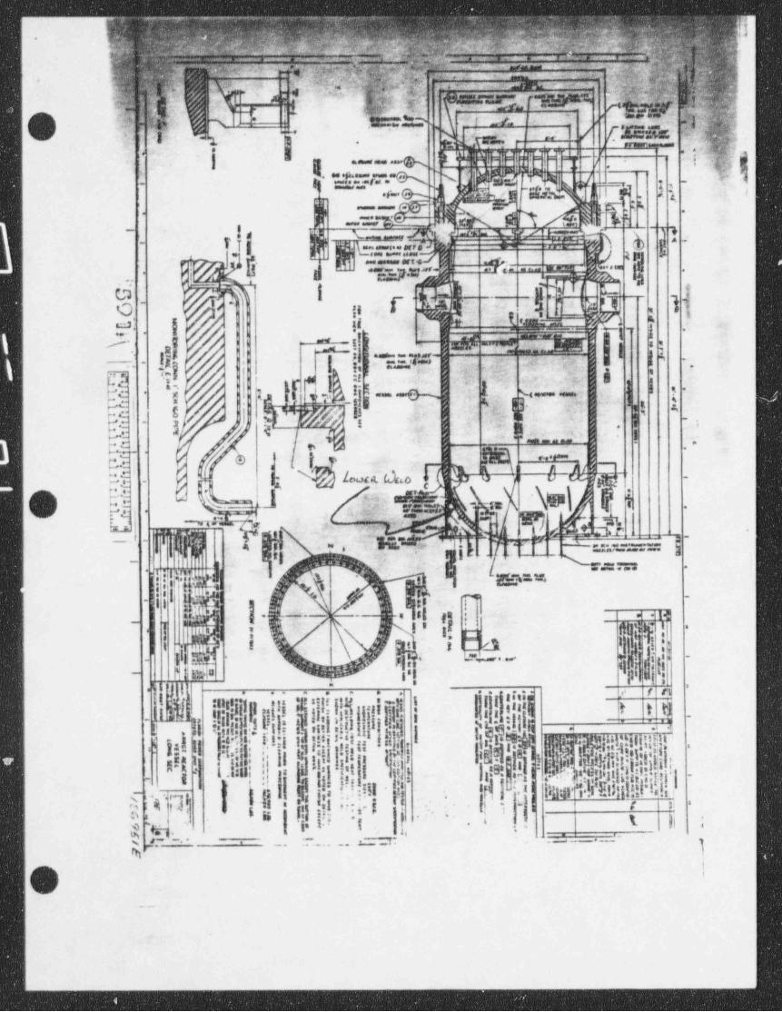
these interferences at the crotch location of the lower transition piece(MK-36), see the attached B&W drawings 15543 and 126951. Due to thecongested nature of the area and the lack of automated equipment to scan theweld, a technician would have to access the area and perform a manualexamination of the weld. It is estimated that the total dose exposureaccumulated to perform this exam would be 25-36 person-REM with anassociated cost of between $250,000.00 and $350,000.00.
,

_- -- . . . - . - -
' U. S. Nuclear Regulatory Commission Attachment 13F0296-07- Page 4
i,
E. Potential for Damage Caused by Examinations. j'
The licensee cites limited access for examination and the potential fordamage of incore instrumentation by the examination tool. Provide a 1
,
detailed access study and determine the actual probability for potentialdamage due to the inspection tooling, )i.e. considering clearance
i requirements,tooloperations,etc.). In addition, provide instances where ;
damage, if any associated with the subject weld has occurred, the result of,
: the use of the inspection tool at your plant or at any other plant with .;
; similar reactor pressure vessel designs.
4
: Response
!The Framatome robotic manipulator (URSULA) employees a two by two matrix of; contact type ultrasonic transducers in the scanning head. In order to scan
a weld, the transducer shoe must be in contact with the vessel surface. As"
can be seen from the attached drawings (B&W Dwg #'s 126951 and 135543) the !'area surrounding the lower head to transition piece weld is extremely
congested with other reactor vessel components, such as the guide lugs, theincore instrumentation guide tubes, and the remnants of the lower flowstabilizers. The reactor vessel component of immediate concern, should an-
impact occur with the URSULA scanning head, are the incore instrument guidetubes. These slender tubes protrude from the inner surface of the lowerhead approximately 12 inches and are less than 1 inch in diameter. |
Alignment of these tubes is critical as they are insertea into a mating tubeon the lower section of the core barrel when it is repl aced. Anymisalignment of these tubes due to an impact with the scanning head wouldcause significant damage not only to the incore guide tube, but also to themating tube on the core support assembly and any adjacent tubes ifsignificant deflection were to occur while installing the core barrel.Repair to the damaged incore instrumentation guide tube and any other affect3
components would cause significant critical path delays to the outageschedule.
Another issue to be contended with is the potential for damage to the URSULAmanipulator arm due to an impact with one or more of the obstructions in the1
vicinity of the weld. This is significant from the stand point of accuratetransducer positioning. If damage were to occur to the arm such that it is,
unable to calculate its position relative to the base unit, accuratepositioning of the UT data being collected would be lost. To recover fromthis situation would entail repair of the manipulator arm and a rescan of ,
the weld; both evolutions adding to the critical path time of the schedule*
and dose exposure for the job.
The first time deployment of the URSULA manipulator to a B&W reactor vessel !
was at ENTERGY's AN0-1. While developing the scan plan for the vesselinspection, it was determined that access to the lower head to transitionpiece weld would be limited to less than 7 %. The scan plan was developed
,
using 3D CAD software (R0BOCAD) which incorporates the actual vessel*,
~ dimensions and all the interferences. This allowed the programmers todetermine how much of the weld would actually be accessible for scanning.
_
yj
-
.: w na, ,-
. . , ,. =
, <.
-
-'
'
'
[s=y a . u, ,._ .,., -- .-
#'
i_
.- .i., _ c
"d.".?/::"." 7|li $ b.. ; , q<-y__,._
z.a3 e o',
,.
1 fC :.4-
' '
fil 7 M c Riii M,
::r's _we sI ..arre P
-' -mg 8 3 -::
- x-- _ sm;;.e_-- 1_' *7>
- --
@ gi .
eel 45#f e. .!." *'".,' ","' 7 E 1...,- .. r g. - -- _ g e aq g gr .
h | E I !
'., [ [1 Li! 't]ji
,,_ _
c /ls p , f- , .i w',
f -. : -1ff si ?. ii|n
<-
n .-
I , ,m e y my. ,
.
Q 'j _. y fi AB. N 3 i |{jg;|p*:";".. 3g-
g '"d k --- '!$5 j f Id L _11 ~'L 'h& ;c k / 3:
-,. ,
x s,) \
q m p f g'/1 f,'i N! |\
, .
b ; gt.,2h .' .,'4fg j_~
$NT ii W ~r['
: -
.,
lootk^ $O''*k '| 4 ( U~
e.
.
'" ' .SE lg, .
% ru -< t av
^%,p:(kW|^ig:-i j- x,.,. , g -1
-
4 .|' l ;-U RM ,&
- l',WE u
,jo y3 y, .
y .
.; || L I q' ->-
w.M 'rj'T '| |
-
gdf'.f
*
3, .
m
hii_a :,i -
i
a .y. -.-
NIM # 89 83* '
| | :-
. .. . .. .. ... < 1
tI " *'
f U|' flik [dI!!jl|flI|! i, ,}Lnom|kfj@m$..i .l'
ip.
>-
. . eh, ,-- It -s ., o
3rrJ! l ! In -.
i ,;:; i.
,' 1 ,
' < e-sg .$
a ; , . .* '
$ c1 ~.. '. ' . . w i .ts t':,,
.
_ ._-
. - . .--- -.
'O.. _

, .tas w,.&-- . 5.yyf M n;igWff S
,g ?ff"IDNj7'TL 75FQhE$,a - . . . d.
, a s,e ."; g-
. - s .- n,_ .p, ppgQygy; _g_ ~+.. n... +;-. :-
,
.
1..u a - - -,;, n 4
, s n,px)3. . , , . j , p. .,
Lt"'-Y
|m f. ., ..
_
, - -a p| ..c - ,g""" m L. -I jIU~
h,.f.---i -,.. g ,,,~,I
,
e !W
;,-
, .
I d
. 3,J L. E '. ' 4.
- / f.-< .
o.: p ..
@M,,,lg jlg N j|
* -
,
d.,f~f[a'i - -,,
, _
//T%p %--. ..
-
. u - s- o e-
Gja x , /gi -
{j h !
thi Fg/jy [!'_..
_
I 1,1. !z -
g & -
1 I P @-13]'
ji 5= ,
.1 p, |Ihgiii g -
1'
' .h[I$ L. .A i-'
-
ii (Y }&n '% . y%y 5% Xq ',.u' gav L> ,.L Worivs 11 %.j i "smi
- ,
O m,, i c*,u' :a, :,
.. t --p
8,0 -
, ,,. --
i,8 ,-
,!, ,
": @-- L
!: I-TTil A :i;$, hif . * ' .!;* i !! :8
a I5 k ''l I i ! *
" . ,o s. .n+ .,
I i i. ~-,
itill fJ ij i5
( ...>i. , ,
Y. [., .j. @ --.
!.E ' !. .
,
t.u , ,.f ~ '- 1 t' f .!'
ff||,
..
! D'id ' 3( Wr'I hv
_
!!! -h _i i,t,SW;! f, ;: ._._ _f,
I
-
d.__
y!'
t-
~A..- x%# '
I a gig- em a veg, .
_w
|j... . .
E stait' { 8 ,%
f,"| I ! I|s
i+SEI! E t
3 s 11->l u ;
g .. :g.n .
O i itif '2e
g.p! S'i l #n.
'
YiEi . ,. .. . . ,. , . , . ,
,