forza - steel-line automation · forza is an electromechanical reversible gear motor, suitable to...
TRANSCRIPT

Instructions and warnings for installation and use
FORZASECTIONAL GARAGE DOOR OPENER

2
EN
1
2
3
4
5
6
7
8
Safety Warnings
2.12.22.32.4
4.14.24.34.44.54.64.74.7.14.7.24.7.34.7.44.7.54.7.64.7.74.7.84.7.94.7.104.84.9
Product OverviewDescription of the ProductParts ListSpecificationsList of Cables Needed
Preliminary Checks
Installing the OpenerAssembly of Guide Rail in 3 PartsConnection of the Motor Body to the Guide RailInstallation of the Guide Rail and Motor on the doorManual Opening of DoorWiring DiagramNormal Mode LCD DisplayProgrammingSetting of Opening LimitSetting of Closing LimitForce Learning ActivationSetting Force LevelRemote TransmitterPhotocell Function SettingSetting of the Duration of Automatic ClosureSetting of Alarm for 2000 Operating CyclesOpening Command SettingEnd of ProgrammingSaving & Deleting Remote TransmittersTroubleshooting
Final Testing of the Opener
Battery Backup Connection
Instructions and Warnings for the end user
EC Declaration of Conformity
p. 3
p. 4p. 4p. 4p. 5p. 6
p. 6
p. 6p. 6p. 7p. 7p. 7p. 8p. 8p. 8p. 8p. 9p. 9p. 9
p. 10p. 10p. 10p. 10p. 11p. 11p. 11p. 12
p. 12
p. 13
p. 13
p. 15
INDEX
3
EN
WARNING - for the safety of personnel, it is important to follow these instructions and save them for future use.
Read the instructions carefully before you start the installation.
The design and manufacture of the devices making up the product and the information contained in this manual comply with safety regulations. However, wrong installation and programming may cause seri-ous physical injury to those who perform the work and those who will use the device. For this reason, during installation, it is important to carefully follow all instructions in this manual.
Do not proceed with the installation if you have any doubts.
In view of this, the final connections to the power supply of the open-er, the system tests, its commissioning and maintenance must be performed by qualified and experienced personnel, according to the instructions in "Final Testing of the Opener".
IMPORTANT - Before starting the installation, perform the following analysis and tests:
Ensure that the individual opener is suitable for the installation to be made. In this regard, check with particular attention the data con-tained in the "Specifications" section. Do not install if the opener is not suitable for use.
Considering the hazards that may occur during in-stallation and use of the product you need to install the opener observing the following precautions:
Do not make changes to any part of the opener, other than those specified in this manual. Any changes made that are not specified in this manual may lead to a malfunction. The manufacturer disclaims any liability for damage arising from products that are not complaint with this manual.
Keep all parts away from water or other liquids. During the installa-tion, ensure that no liquid can penetrate into the opener.
If liquid spills into any part of the opener components, immediately disconnect the power supply and contact your opener supplier. The use of the opener under these conditions can be dangerous.
Do not place the various components near sources of heat and do not expose them to open flame. These actions may damage them and cause malfunctions, fire or danger.
All operations requiring the opening of the protective cover opener, must be performed with the control unit disconnected from the main supply.
The control unit must be connected to a power supply line provided with earth connection;
The product cannot be considered an effective system of protection against intrusion. If security is of concern, you need to integrate the opener with other devices;
The product can be used only after the commissioning of opener has been made, as provided in Section 5 - "Final Testing of the Opener" ;
For the connection of pipes and conduit or guides, use pipefittings with IP55 degree of protection or higher;
The electric system upstream of the opener shall comply with cur-rent regulations;
This opener is not intended for use by persons (including children) whose physical, sensory or mental abilities are reduced, or who have lack of experience or knowledge, unless under supervision of a suitable person;
Children should be supervised to make sure they do not play with the device;
WARNING - The packaging material of all compo-nents should be disposed in compliance with local regulations.
WARNING - The data and information provided in this manual are subject to change at any time without no-tice.
1 - SAFETY WARNINGS

4
EN
2.1 Description of the product
Forza is an electromechanical reversible gear motor, suitable to au-tomate sectional doors up to 16 m2. Forza has a built-in encoder, control unit and receiver.
The receiver can be set to select fix or rolling code ‘transmitting devices. The guide rail is belt driven, pre-assembled in one or three pieces.
2 - PRODUCT OVERVIEW
2.2 Parts listThe system for garage door automation is composed of two boxes. One contains the opener motor; the other contains the guide rail assembly, as shown in the illustration below.
Parts List
Part Name Quantity
Opener Motor 1
Instruction & Installation Manual 1
Curved arm for door 1
Mounting plate 2
Guide Rail Support 1
U bracket 3
Guide Rail Mounting Bracket 1
Door bracket 1
Package of Fasteners
(8 off) - 6x15 hex-head self-tapping screw (1 off) - 6x80 Screw with hex nut
(1 off) - 8x25 Hinge pin (1 off) - 3x20 Split pin (1 off) - Drive Spacer
(6 off) - 6x80 Expansion plug (4 off) - 8x20 Screw with hex nut
Guide PackagePre-assembled Guide Rail
Guide Rail (1 off) Straight arm for door (1 off)
Belt (1 off) Emergency cord (1 off)
Carriage or Trolley Assembly (1 off)

5
EN
TECHNICAL DATA SEZ12SLInput Voltage 190V - 240V Power 24 Vdc Consumption power 160 W Motor consumption 6,66 A Protection degree IP 43 Force 1200 N Speed 11 cm/s Stroke 2,8 m Light 25 W (1x) E14 Max door size 16 m2
Working cycle 60 % Working temperature -20° + 55° °C Weight 11 Kg
2.3 Specifications
LIMITS OF USAGE
Sectional Door Dimensions
H max = 2,7 m
W max = 5.9 mm² max =16 m2
35
155
370
200
65
3080
CODE DESCRIPTION FORCE GUIDE RAIL
SEZ12SL for sectional doors up to 16 m2 with motor 24 Vdc and con-trol unit with built-in receiver 1200N belt driven pre-assembled 3320 mm in one
piece
output power for accessories 24V/800 mA
EN
6
3 - PRELIMINARY CHECKS
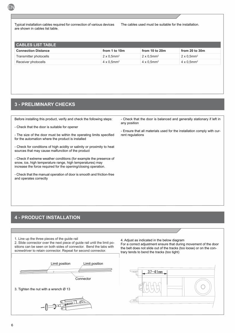
Before installing this product, verify and check the following steps:
- Check that the door is suitable for opener
- The size of the door must be within the operating limits specified for the automation where the product is installed
- Check for conditions of high acidity or salinity or proximity to heat sources that may cause malfunction of the product
- Check if extreme weather conditions (for example the presence of snow, ice, high temperature range, high temperatures) may increase the force required for the opening/closing operation.
- Check that the manual operation of door is smooth and friction-free and operates correctly
- Check that the door is balanced and generally stationary if left in any position
- Ensure that all materials used for the installation comply with cur-rent regulations
4 - PRODUCT INSTALLATION
4.1 Assembly of Guide Rail in 3 Parts
1. Line up the three pieces of the guide rail2. Slide connector over the next piece of guide rail until the limit po-sitions can be seen on both sides of connector. Bend the tabs with screwdriver to retain connector. Repeat for second connector.
3. Tighten the nut with a wrench Ø 13
4. Adjust as indicated in the below diagram For a correct adjustment ensure that during movement of the door the belt does not slide out of the tracks (too loose) or on the con-trary tends to bend the tracks (too tight)
Limit position
Connector
Limit position
2.5 List of Cables Needed
Typical installation cables required for connection of various devices are shown in cables list table.
CABLES LIST TABLE Connection Distance from 1 to 10m from 10 to 20m from 20 to 30mTransmitter photocells 2 x 0,5mm2 2 x 0,5mm2 2 x 0,5mm2
Receiver photocells 4 x 0,5mm2 4 x 0,5mm2 4 x 0,5mm2
The cables used must be suitable for the installation.
7
EN
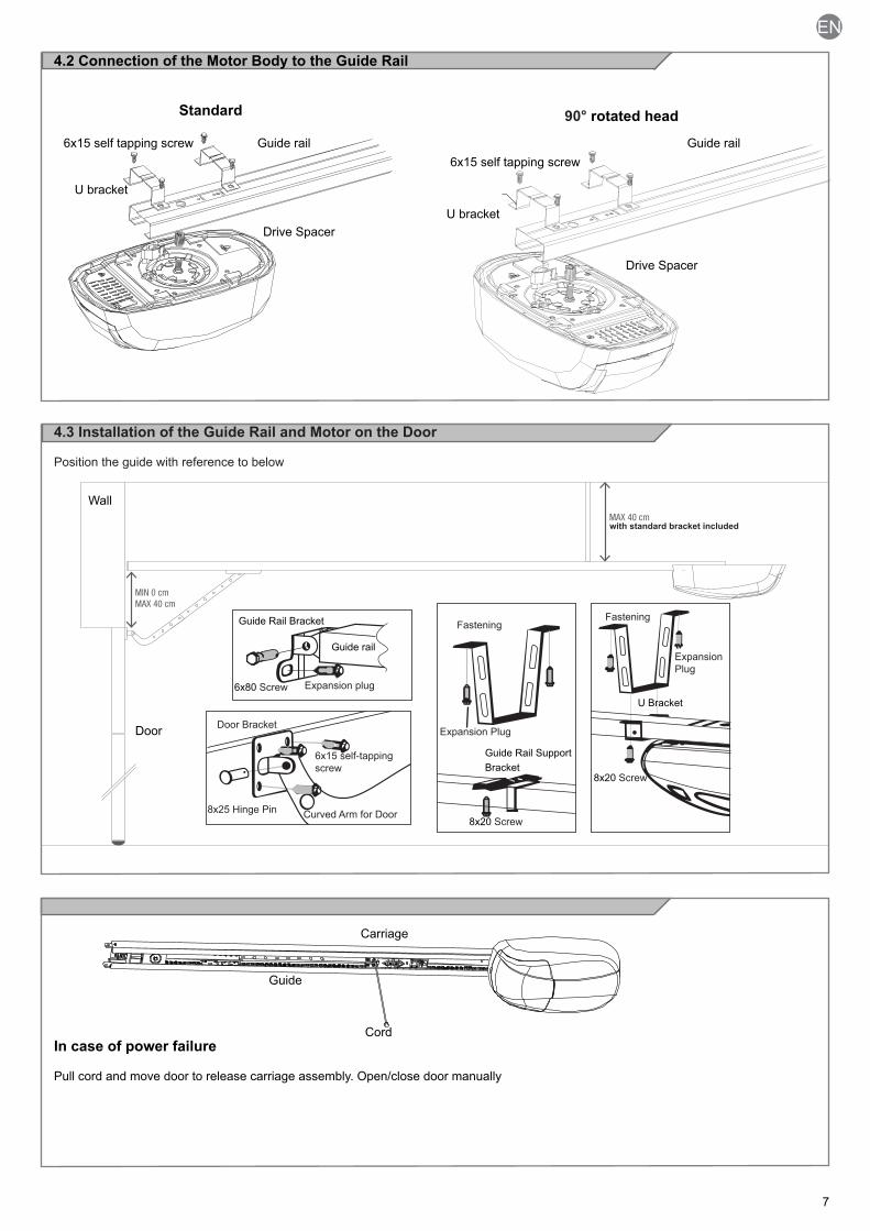
MIN 0 cmMAX 40 cm
MAX 40 cm
Wall
Door
Guide Rail Bracket
U Bracket
Guide Rail Support Bracket
6x80 Screw
Guide rail
Expansion plug
Expansion Plug
Expansion Plug
8x25 Hinge Pin8x20 Screw
8x20 Screw
Curved Arm for Door
6x15 self-tapping screw
Door Bracket
FasteningFastening
with standard bracket included
4.2 Connection of the Motor Body to the Guide Rail
6x15 self tapping screw
U bracket
Guide rail Guide rail
Drive Spacer
90° rotated headStandard
6x15 self tapping screw
U bracket
Drive Spacer
4.4 Manual Opening of Door
Guide
Carriage
CordIn case of power failure
Pull cord and move door to release carriage assembly. Open/close door manually
4.3 Installation of the Guide Rail and Motor on the Door
Position the guide with reference to below

EN
8
4.6 Normal Mode LCD Display
In “NORMAL MODE”, when the installation is powered normally, the right hand digit of 2-digit LCD displays rotates and after 30 sec. will turn off
4.5 Wiring Diagram
WARNING - Before making connections verify that there is no power to openerWiring diagram for optional photocells and Open/Stop/Close command (O/S/C).
Photocells must be fitted by qualified personnel. Remove factory bridge across connections 4 & 5 prior to wiring photocells.O/S/C must be connected between no. 2 and no. 1 (contact normally open N/O)
4.7 ProgrammingPreparation A. Gently move the door to ensure carriage is engaged on guide rail (door should be in closed position).
B. Power on. The light will turn on, the unit provides a single audible signal and the display indicates”0”.Attention: If programming is not complete, the settings will be cancelled automatically. If incorrect setting has been pro-grammed, power off and then power back on, following steps below.Warning: Programming of functions from 4.7.1 to 4.7.3 are mandatory. It is possible to end the programming phase and save data in any step on the functions menu from 4.7.3 to 4.7.9. Refer Step 4.7.10.
4.7.1 Setting of Opening Limit
Press the key “P” for 5 seconds
Press”+” Or press “-”
The unit emits 1 beep and “1” is displayed.
Door opening Door closing
Press “P”, “1” flashes
When the door opens and reaches the ideal position, press “P” to save the information.
Warning: the saved information has no effect if this procedure is used for setting the limit of closing
1
2
4
35
Description of the buttons1 - P function button2 - S setting up remote transmitters3 - + parameter increase button4 - - parameters decrease button5 - Display
COMMON
3 41 2 1 2TX RX
NC
24Vac/dc- +
24Vac/dc- +
Rec
eive
r Display
Limit switchENCODER
+24VPhotocell-Shared
STO
P
COM
O/S
/C
TX RX

9
EN
4.7.2 Setting of Closing Limit
Press”+” to display “2” Door closing or door openingPress “P”, “2” will flash
When the door closes and reaches the ideal position, after 2 seconds press the key “P” to save the information.
Press”+” Or press “-”
4.7.3 Force Learning Activation
Press ”+” to display “3” Press “P” when door stops, then again press “P”
Press “P”, “3” flashes
Door closes automatically
The door opens automatically
Press “P” to save the settings if you wish to continue with 4.7.4orPress and hold “P” for 5 seconds to save the settings and exit programming
Press “P”, ” ” flashes Press”+”, or press ”-” to select the level
4.7.4 Setting Force Level
Press ”+” to display “4”
Default setting
Force level LowHigh
Press “P” to save the settings
C
When programming is finished the door must make a full cycle before usage, this cycle is used to learn the force after the modification made.
If you wish to over-ride the settings from step 4.7.3 follow this step. Note: To exit the programming and save the parameters push P button for 5 seconds.
Note: In order to avoid activating the obstacle safety system in setting the closing limit it is strongly it is strongly recommended to release the button as soon as the door touches the ground.
Note: If “P” is pressed to save setting and then you wish to save & exit programming, please proceed to first step of 4.7.4 and then press & hold “P” for 5 seconds. Otherwise saving & exiting after saving the closing setting will trigger door to open again, however all parameters are saved and display will revert to Normal Mode. Door can be closed by pressing “-” button.

EN
10
This step is not required if using a ‘Forza’ remote transmitter. Default setting is “1”.
Press”+” to display “5”
Press”+” to display “7”
Press”+” to display “6”Photocell is always active in closing
Press “P”, on the display ‘1” flashes, to indicate that the set radio decoding is ROLLING CODE (default setting); if 2 is selected on the display the set radio decoding is FIX CODE
Press “+” or “-” to select the desired type of decoding
Press the key “P” to show “5”, and save the settings.
4.7.6 Photocell Function SettingThrough this function with the door closed and photocell interrupted, it is possible to enable/disable the opening command(Default setting is “0”)
Press “P”, the display shows 0, to indicate that the photocell is not active during opening (default setting)
Press”+”, the display shows 1, to indicate that the photocell is ac-tive during opening
Press “P” again to save the settings
4.7.7 Setting of the Duration of Automatic Closure
For safety reasons this setting should only be used with the optional photocell beam. (Default setting is “0”)
Press “P” to show “0”, the func-tion is not active (default setting)
Press”+” to show “1” and activate the function. This setting activates automatic closing after 5 seconds.
Press “+”,or “-” to select the dura-tion following the table belowPress “P” again to save the set-tings.
4.7.5 Setting Reception Mode
4.7.8 Setting of Alarm for 2000 Operating Cycles
(Default setting is “0”)
Press”+” to display “8” Press “P”. The display shows “0” to indicate that the function is not active (default setting)
Press “+”. The display shows “1” to indicate that the function is active
Press “P” again to save the settings
Silencing the acoustic alarm: power off, then power on again, or press the door control keys either “+” or “-” for 5 seconds
Value 0 1 2 3 4 5 6 7 8Time not active 5 sec 10 sec 20 sec 30 sec 60 sec 120 sec 180 sec 240 sec
Note: To exit the programming and save the parameters push P button for 5 seconds.
Note: To exit the programming and save the parameters push P button for 5 seconds.
Note: To exit the programming and save the parameters push P button for 5 seconds.
Note: To exit the programming and save the parameters push P button for 5 seconds.

11
EN
Press”+” to display “9” Press “P”, the display shows “0” to indicate that the step/step command has the Open/Stop/Close function (default setting)
Press”+”, “1” appears to indicate that the step/step command can only open
4.7.9 Opening Command SettingFor safety reasons this setting should be used in conjunction with optional photocell beam. Default setting is “0”. It is possible to change the functioning of the open/stop/close step by step command to only open
By enabling this function, the Step/Step command permits opening by accepting only re-opening during closing.With step 4.7.7 set at “1” or more automatic closure enabled at each command the automatic closing time is updatedWith step 4.7.7 set at “0” auto-matic closure disabled with the door open it is possible to re-close it using the step/step com-mand
4.7.10 End of ProgrammingWarning: programming of functions from 4.7.1 to 4.7.3 are mandatory. It is possible to end the programming phase and save data in any step on the functions menu from 4.7.3 to 4.7.9 by taking following steps:
To exit after any parameter from 3 to 9 (eg. step 4) press and hold “P” for 5 seconds
Modifications made before this step will be saved
A beep followed by a sliding “0” indicates that the programming procedure has concluded suc-cessfully
4.8 Saving & Deleting Remote Transmitters
Follow the procedure below to memorize ROLLING CODE transmit-ters. To save FIX CODE transmitters follow the paragraph 4.7.5, then after memorize transmitters as indicated here below.
1. Saving or Adding Remote Transmitters• Press the S button until “0” appears• Release the S button• Press the button of the transmitter to be memorised• The “0” on the display disappears, the transmitter has been saved• For each transmitter (maximum 20) repeat the procedure for each single transmitter
2. Deletion of a single transmitter• Press and hold both the P & S buttons for the next two steps• Press the button of the transmitter to be deleted until the control unit emits a beeping sound• Release the transmitter button• This procedure will delete all the buttons regarding that transmitter
3. Deletion of all transmitters• Switch off the 240 Vac power supply• Press and hold the S button• Switch on the 240 Vac power supply while holding the S button for 5 seconds until you hear the 2 beeps from the control unit
4. Wall switch and courtesy light programming• Push S button until “0” appears• Release S button• Push S button again until “0” starts to flash• Release S button• In order to switch on the courtesy light push the remote control button or wall switch button to be memorized
N.B: Once activated the courtesy light will stay on for 180 sec; in case of reactivation the courtesy light counter will re-start from zero. It is possible to memorize just one button with the courtesy light function.
BUZZER SIGNAL MEANING
1 beep code memorized
2 beeps code already memorised
3 beeps memory full
Note: To exit the programming and save the parameters push P button for 5 seconds.

EN
12
4.9 Troubleshooting
Following is list of some malfunctions that may happen.The LCD screen will also show some malfunction codes.
Problem Causes SolutionThe opener does not work 1. The electrical plug is not inserted firmly
2. The fuse is blown1. Check plug. Contact electrician if power point faulty2. Contact electrician to replace fuse with same fuse type
The range of the transmitter is excessively limited
The battery is low on power Replace the battery with a new one of the same type
The drive belt moves, but the door does not move
The carriage system is disengaged Lock the carriage as per Step 4.4
The alarm continues to sound Alarm: 2000 cycles of operation Disconnect the power supply, then power back on
The door is not in position when it is opened or closed, or it does not work
Incorrect setting Re-program opener again
The door does not work correctly, and the screen shows "H"
Control unit problem due to high humidity Dry the unit (request assistance from a technician)
Sudden interruptions or jerks in the operat-ing system, and the screen shows "F"
1. The tension spring is loose or out of adjustment 2. Obstacle safety system activated with no obstacle3 The power supply is not stable
1. Adjust the traction spring. 2. Adjust the force setting (step 4.7..4) to the suitable level until “F” disappears3. Contact electrician to check power supply
During operation, you can hear a screeching noise
Lack of lubricant between the guide and carriage after a long period of use
Lubricate or grease the point between the guide rail and the carriage
The testing of the opener should be performed by qualified techni-cians.
All installed components should be tested following the procedures outlined in this instruction manual
Check that they meet the guidelines in Chapter 1 - Safety warningsCheck that the door can move freely once the automation is dis-engaged, and that they are balanced and generally stationary if left in any position
Check the correct operation of all connected devices (photocells, etc.), testing the opening, closing and stopping of the door via the connected control devices (transmitters, buttons, switches)
Carry out an obstacle test using a block of 50mm wood on floor un-derneath door to ensure the door reverses on hitting the obstacle. adjust force setting, if required, to ensure safe operation of door
Ensure this manual is given to the end user of door.
Attach the label indicating the steps required to manually dis-en-gage the opener
Make sure the end user understands properly the automatic, manu-al and emergency operation of the opener.
WARNING - after detecting an obstacle, the door stops and re-verses, the automatic closing function (if set) will not operate. To restore this function press wall button or remote transmitter to close door.
5 - FINAL TESTING OF THE OPENER
13
EN
6 - BATTERY BACKUP CONNECTION
Forza opener can also function in the absence of main power supply by installing the optional external Battery Backup Model 900KBPK without making any modifications to the system.
IMPORTANT: If using battery backup with optional photocells, it is necessary to connect the power of the photocells in the con-nectors CH+ and CH-.
Each installation is unique and only your installer has the experi-ence and professionalism required to create an installation to suit your needs, is safe and reliable over time, and carried out according to the good industry practice, i.e. compliant with the current regula-tions. Even if your opener meets the security level required by law, this does not exclude the existence of “residual risks”, i.e. the pos-sibility that it may cause dangerous situations, usually as a result of improper or irresponsible use; for this reason we would like to give you some suggestions:
• Before using the opener for the first time, ask the installer to high-light any potential of risks.Keep this manual for future use and deliver it to any new owner of the opener.
• Inappropriate or improper use of the opemer can make it danger-ous: do not operate the opener if people, animals or obstacles are in its range.
• Children: If properly designed, the opener ensures a high degree of security, preventing movement in the presence of people or things with its detection systems, and ensuring always predictable and safe activation. It is prudent to prevent children from playing near the opener and keep wall switches and remote transmitters out of their reach to prevent accidental activation.
• Malfunctions: As soon as you notice any malfunctions, disconnect the installation from the power supply and operate the manual re-lease. Do not attempt any repairs by yourself, but seek the assis-tance of qualified personnel. In the meantime the door should be operated manually until the malfunction is fixed.
• In case of power failures: if the installation is not equipped with backup batteries, the opener can be operated as a manual door. To do this, you must dis-engage the carriage on guide rail.
• Maintenance: Like any machine, your opener needs periodic main-tenance to ensure its long life and total safety. Boss Openers recom-mend a frequency of 12 months for normal domestic use, but this period may vary depending on the intensity of use. All inspection, maintenance or repairs should be performed only by qualified per-sonnel.
• The end user should periodically clean the covers of the photocells (clean only with a cloth slightly dampened with water), as well as the remove of any obstructions, should as leaves or rocks that could block the operation of door. To prevent anyone from activating the door, before proceeding, remember to dis-engage the opener.
Replacing the remote transmitter battery: if your remote transmitter range is reducing over time, or not work at all, this may mean bat-tery is low on power (depending on use, it may take several months to over a year). In that case, you will see that the light on remote transmitter does not turn on, or comes on only briefly. Replace bat-tery with same type, or equivalent type to one installed.
7 - INSTRUCTIONS AND WARNINGS FOR THE END USER
Connection sequence:• Disconnect the 240 VAC power supply• Connect 900KBPK to terminals CH+ and CH- .• Re-connect the mains power supply• New batteries charge up after about ten hours.

14
NOTES

15
8 - DECLARATION OF CONFORMITY
DECLARATION OF CONFORMITY “CE”
The manufacturer: Key Automation S.r.l.
Address: Via Alessandro Volta, 30 - 30020 Noventa di Piave (VE)
DECLARES THAT THE FOLLOWING EQUIPMENT
Description: Sectional gear motor for garage automation
Model: FORZA
Code: SEZ12SL
Is in conformity with the following community (EC) regulations:
Machinery Directive 2006/42/EC Low Voltage Directive 2006/95/ECEMC Directive 2004/108/EC
Is in conformity with the following harmonized standards regulations:
EN 55014-1 + EN 55014-2EN 61000-3-2 + EN 61000-3-3EN 60335-1 + EN 60335-2EN 55022
He declares, moreover, that it is not allowed to use the above mentioned product until the machine, in which this product isincorporated, has been identified and declared in conformity with the regulation 2006/42/EC.
Il Rappresentante legale The legal Representative Nicola Michelin
