foundation report for crossing at - aina …pubs.aina.ucalgary.ca/gran/33394.pdf · ·...
TRANSCRIPT


FOUNDATION REPORT FOR CROSSING
AT
RIVER BETWEEN TWO MOUNTAINS
MILE 411 MACKENZIE HIGHWAY
NORTHWEST TERRITORIES
ACRES CONSULTING SERVICES LIMITED S u i t e 990 - 125 - 9 Ave. S.E.
Calgary, Alberta T2G OP6

TABLE OF CONTENTS
Page No.
1. 2. 3 .
4. 5.
5.1
5.2 5.3
INTRODUCTION 1 SITE AND GEOLOGY FIELD INVESTIGATION AND LABORATORY TESTING
1
2 FOUNDATION CONDITIONS 3 RECOMMENDATIONS AND CONCLUSIONS Abutment and Pier Foundation Design
5
5 Lateral Abutment Loads 7 Bridge Approach Embankments 8
APPENDIX
LEGEND NOTES RELATING TO PHOTOMOSAICS DEFINITIONS Figure 1 -
Figure 2 -
Figure 3 -
Figure 4 -
-
A-1 A-2 A-3
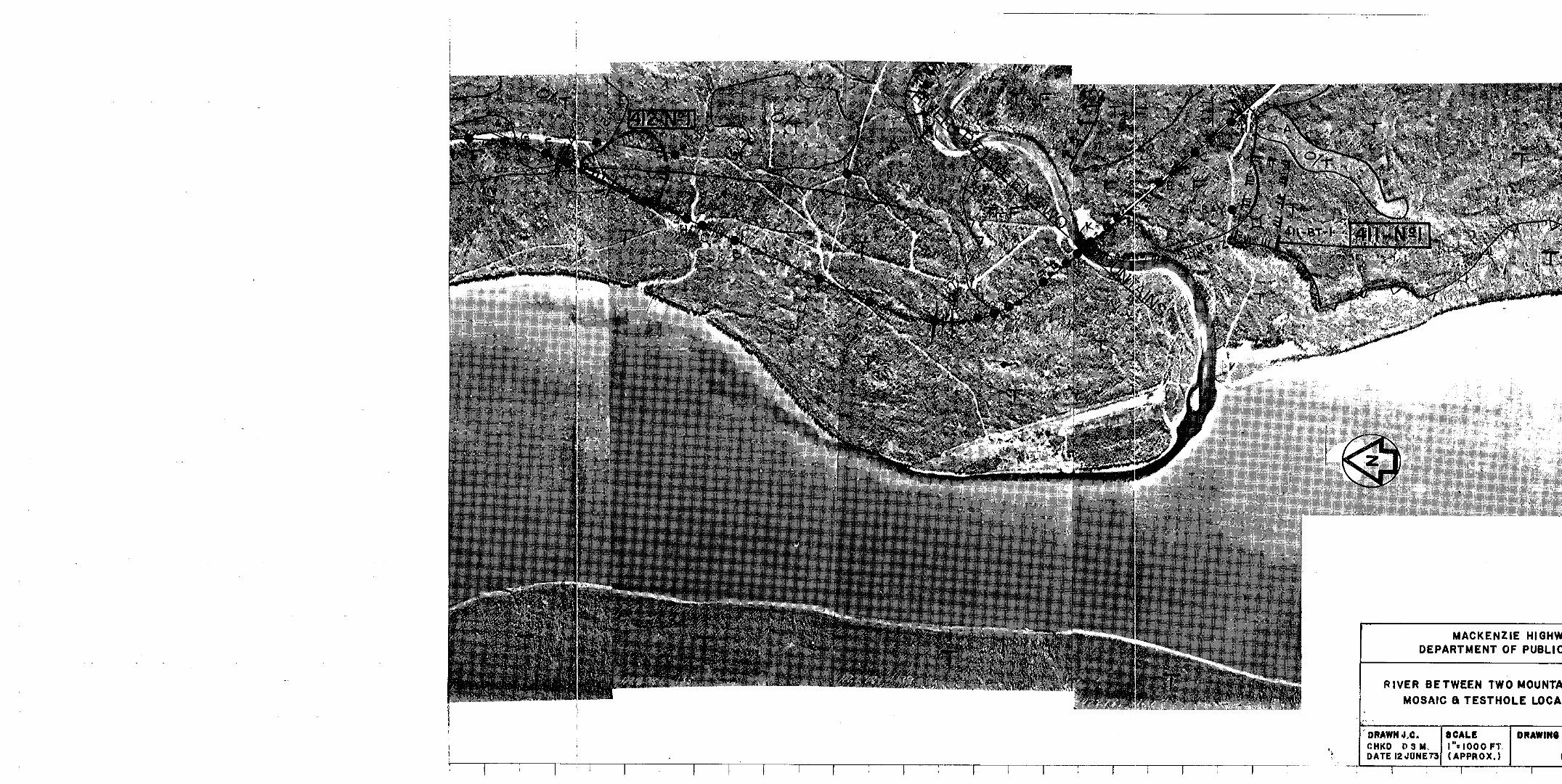
MOSAIC AND TESTHOLE LOCATION PLAN SITE CROSS SECTION AND BOREHOLE PROFILES UNIFIED SOIL CLASSIFICATION SYSTEM NRC/ACFEL ICE CLASSIFICATION SYSTEM TESTHOLE LOGS :
411-C-H 411-C-I 411-S-J 411-S-K 411-S-M 411-C-N 411-C-0

a
a
111
1.0 INTRODUCTION
This report contains the results of the foundation in- vestigation and recommendations for foundation and em- bankment design for the River Between Two Mountains crossing at Mile 411 on the Mackenzie Highway, Northwest Territories. The field investigation at this site was part of the overall geotechnical investigation conduc- ted by Acres Consulting Services from Mile 346 to Mile 450 on the Mackenzie Highway for the Department of Public Works, Government of Canada.
The purpose of the investigation was to determine the site foundation, permafrost and groundwater conditions and to provide recommendations on the design and con- struction of the proposed bridge piers and abutments, and approach embankments.
2.0 SITE AND GEOLOGY
The River Between Two Mountains crossing site is located at Mile 411.6 (chainage 874 + 00) on the Mackenzie Highway. This site is approximately 1/2 mile upstream from the junction of the River Between Two Mountains with the Mackenzie River.
The crossing site is located at the mouth of the River Between Two Mountains valley where it enters the valley of the Mackenzie. Borings to a maximum depth of 6 0
feet revealed very dense, alluvial, sand, gravel, cobbles and boulders as the foundation material indicating the bridge site is located on coarse fluvial fan. Although bedrock was not encountered at this site, bedrock in the
1.
2 . 0 S I T E AND GEOLOGY Continued
a r e a i s h o r i z o n t a l l y b e d d e d s h a l e , s i l t s t o n e , s a n d s t o n e ,
and l imestone of t h e For t Simpson Formation of Devonian age. The stream bed e l eva t ion a t the p roposed c ross ing s i t e i s approximately 276 f e e t (D.P.W. datum). The length of t h e b r i d g e i s 2 6 0 f e e t and 3 spans are proposed by
t h e b r i d g e c o n s u l t a n t s .
3 . 0 FIELD INVESTIGATION AND LABORATORY TESTING
A t o t a l o f s e v e n t e s t h o l e s were d r i l l e d a t t h e c r o s s i n g
s i t e a long cen t r e l ine t o dep ths r ang ing f rom 8 t o 6 0
f e e t a t locations shown i n F i g u r e 1. Holes were d r i l l e d
on the br idge abutment si tes t o d e p t h s o f 40 t o 60 f e e t . One ho le was d r i l l e d i n t h e r i v e r b o t t o m t o a depth o f 6 0 feet . Four holes were d r i l l e d on t h e f l o o d p l a i n f o r
the approach embankments t o depths ranging f rom 8 t o 1 5
feet. F igu re 2 shows a c e n t r e l i n e s e c t i o n of t h e s i t e .
The d r i l l i n g and sampling a t t h e c r o s s i n g s i t e was done
between February 9 and February 11, 1973 by Kenting Big I n d i a n o f C a l g a r y u t i l i z i n g a Gardner-Denver 2 0 0 " h e l i d r i l l "
mounted on a Foremost 6 0 t r a c k e d v e h i c l e .
Sampling was done us ing the a i r recovery percussion method f o r d i s t u r b e d s a m p l e s , 3 inch th in-wal led She lby tubes for und i s tu rbed cohes ive so i l s amples and t he s t anda rd sp l i t spoon fo r g ranu la r soil samples . S tandard Penet ra t ion blow
counts were t a k e n w i t h t h e s p l i t s p o o n s a m p l e r .
Samples were l o g g e d i n t h e f i e l d a n d c l a s s i f i e d a c c o r d i n g t o t h e U n i f i e d S o i l C l a s s i f i c a t i o n Sys tem as shown i n F i g u r e 3 .
2 .

c
c
L.
3 . 0 F IELD INVESTIGATION AND LABORATORY TESTING - Continued
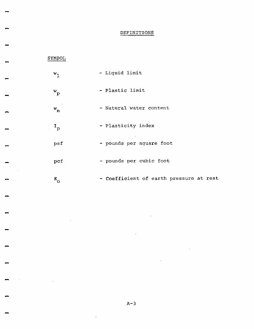
Ice c o n t e n t s were c l a s s i f i e d a c c o r d i n g t o t h e N.R.C.
Technical Memorandum N o . 7 5 "Guide t o t h e F i e l d Des-
c r i p t i o n o f P e r m a f r o s t " as shown i n F igure 4 .
Mois ture conten ts were o b t a i n e d f o r a l l s a m p l e s re- tu rned t o the laboratory and the samples were sub- j e c t e d t o r o u t i n e c l a s s i f i c a t i o n tests i n c l u d i n g g r a i n
s i z e d i s t r i b u t i o n and At te rberg limits. The r e s u l t s
o f a l l l a b o r a t o r y a n d f i e l d tes ts are inc luded i n t h e t e s t h o l e loqs appended t o t h i s r e p o r t .
4 . 0 FOUNDATION CONDITIONS
The fo l lowing boreholes were d r i l l e d t o i n v e s t i g a t e the founda t ion cond i t ions a t t he b r idge abu tmen t and p i e r l o c a t i o n s : -
HOLE NUMBER LOCATION
411-S-K
411-S-J 411-S-M
South Abutment River Cent re
North Abutment
The d e t a i l e d s o i l d e s c r i p t i o n s f o r t h e s e h o l e s i s g iven
i n t h e b o r e h o l e logs appended t o t h i s r e p o r t . Only one
t e s t h o l e w a s d r i l l e d i n t h e centre o f t h e r i v e r t o p r o -
v i d e d a t a f o r t h e p i e r s . A r e v i e w o f t h e t e s t h o l e s d r i l l e d a t t h i s s i t e showed an a d d i t i o n a l p i e r h o l e w a s n o t warranted due to the un i form foundat ion con- d i t i ons encoun te red t h roughou t t h e a r e a .
c
c
3 .

4 . 0 FOUNDATION CONDITIONS - Continued
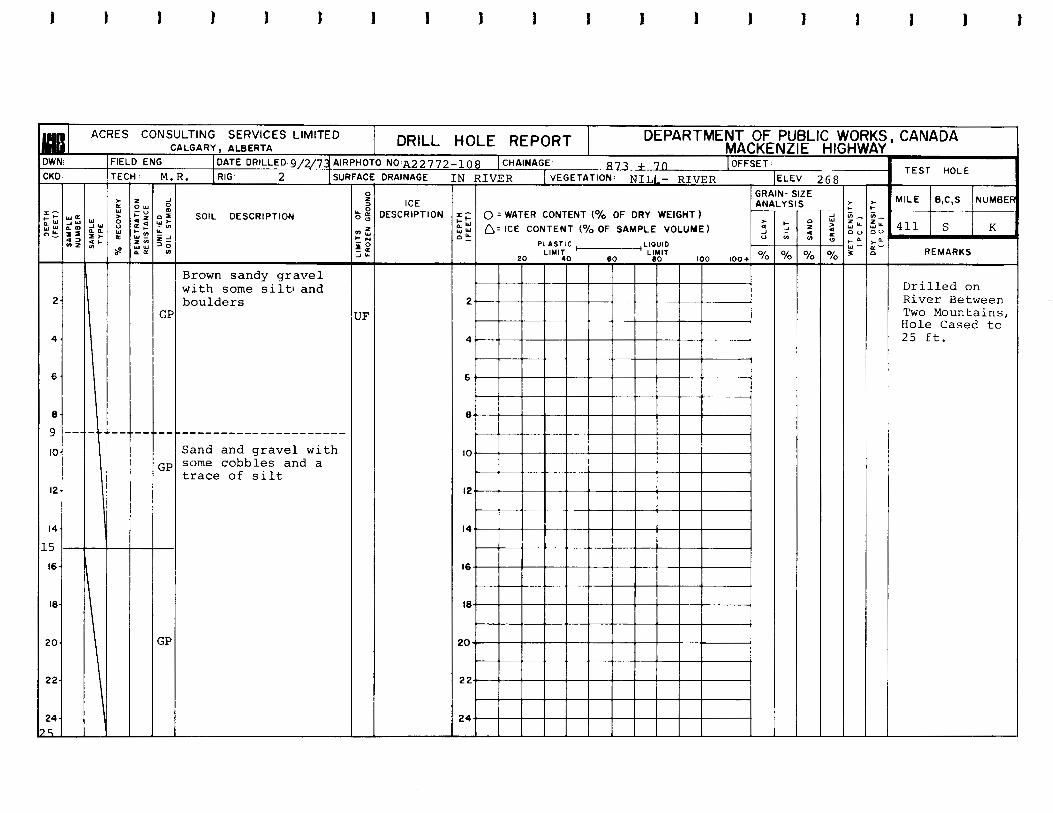
Tes thole 411-S-J was d r i l l e d t o a depth of 6 0 f e e t i n t o
t h e r i v e r b e d . The s o i l was unfrozen throughout the en- t i r e dep th o f t he ho le and cons i s t ed o f ve ry dense s and , g r a v e l , and boulders with a t r a c e o f s i l t . Blow counts f rom the S t anda rd Pene t r a t ion t e s t ranged from 4 6 p e r
f o o t t o 50 blows per 4 i nches or v i r t u a l r e f u s a l .
Tes tho le 411-S-K w a s d r i l l e d t o a depth of 6 0 f e e t on t h e s i te of the south abutment . The s o i l was unfrozen t h r o u g h o u t t h e e n t i r e d e p t h o f t h e h o l e a n d c o n s i s t e d of very dense sand and gravel with boulders and a trace of s i l t . B l o w coun t s f rom the S t anda rd Pene t r a t ion tes t were very high and ranged from 50 blows per 6 i n c h e s t o 50 blows p e r 1 inch or v i r t u a l r e f u s a l .
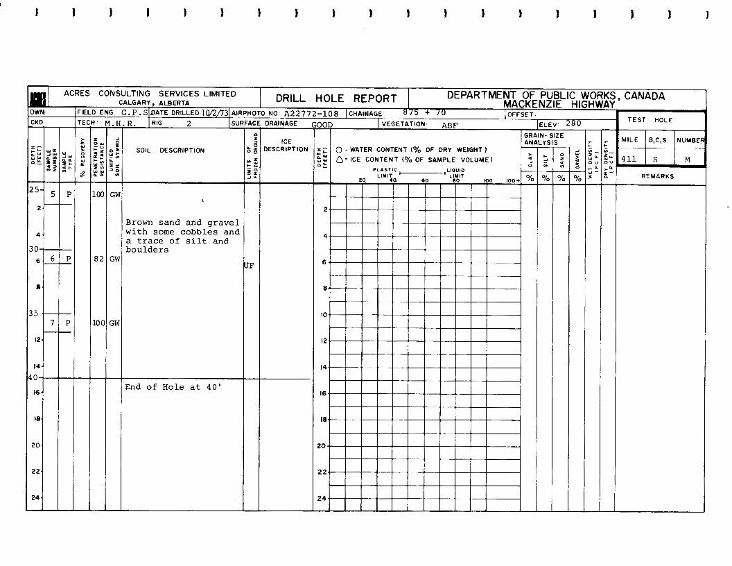
Tes tho le 411-S-M was l o c a t e d on t h e s i t e of t h e n o r t h
abutment and was d r i l l e d t o a depth o f 4 0 f e e t . The
founda t ion cond i t ions were similar t o t h e p r e v i o u s t w o ho les and cons is ted o f very dense ,unf rozen , sand and g rave l w i th cobb les t h roughou t t he fu l l dep th o f t he h o l e . B l o w counts ranged from 82 p e r f o o t t o 20 p e r z e r o p e n e t r a t i o n or r e f u s a l .
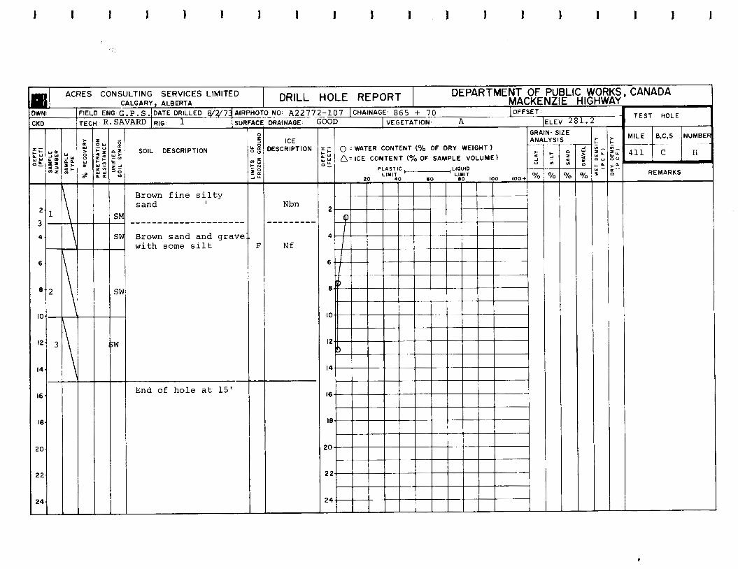
The t e s t h o l e s d r i l l e d on t he f l oodp la in on bo th s ides o f
t h e r iver showed dense sand and grave l over la in loca l ly
by 1 t o 4 fee t o f p e a t a n d s e v e r a l f e e t o f f i n e s i l t y - sand.
The p e a t and s i l t y - s a n d a r e character ized by high water
contents and hence have a l o w , undra ined shear s t rength .
The soils i n t h e s e h o l e s were f rozen t h roughou t w i th t he excep t ion o f t e s tho le 411-C-N w h e r e t h e s o i l was unfrozen f r o m 1 3 fee t t o t h e e n d o f h o l e a t 15 fee t .
4 .

5.0 RECOMMENDATIONS AND CONCLUSIONS
The following conclusions and recommendations are made, based upon the results of the investigation program, for the design and construction of the River Between Two Mountains bridge foundations and approach fills.
5.1 Pier and Abutment Foundation Design
The subsurface investigation program previously descri- bed shows that the foundations at this site are composed of uniform, unfrozen, very dense sand and gravel with cobbles and boulders. It is recommended that considera- tion be given to founding the abutments and piers on spread footings in the dense granular alluvium below the depth of seasonal frost penetration. An allowable bear- ing capacity of 3 tons per square foot is recommended.
If however, due to considerations of river scour, frost penetration, and lateral pier and abutment loads, a more conservative foundation method is considered necessary, a driven friction pile foundation is recommended for the bridge piers and abutments.
Friction pile types include precast concrete and steel pipe and H piles. Steel H piles are recommended primarily for their high driving strength, high load capacity and ease of splicing. The pile section selected should have a flange and web thickness no less than 9/16 inch.
It is recommended that all piles be driven to a depth of 30 feet or "refusal". As an initial guide, it is recom- mended that "refusal" be considered to be 360 blows per foot (30 blows per inch) under a hammer rated at 15,000 ft-lb.
5.

5 . 1 P i e r and Abutment Foundation Design - Continued
Ultimate capac i ty should be e s t a b l i s h e d i n t h e f i e l d by use of dynamic p i l e d r i v i n g f o r m u l a e . The Janbu formula (Terzaghi and Peck, 1967 ) should be used with
a f a c t o r of s a f e t y of 3 t o e s t a b l i s h a n a l l o w a b l e l o a d p e r p i l e .
1
I f r e f u s a l i s no t ach ieved du r ing d r iv ing , t he capac i ty o f t h e p i l e c a n be ca l cu la t ed based upon f r i c t i o n b e t w e e n t h e p i l e and t h e g r a n u l a r s o i l .
I t i s recommended t h a t f o r i n i t i a l d e s i g n p u r p o s e s , t h e a l lowable bear ing capac i ty be based upon a f r i c t i o n o f
800 p s f o v e r t h e s u r f a c e a r e a o f t h e H p i l e . Thus an HP 10 x 57 pi le would have an a l lowable bear ing capaci ty of approximately 50 t o n s i f d r i v e n t o a depth of 30 f e e t . This f igure should be conf i rmed by use o f dynamic p i le f o r m u l a d u r i n g p i l e d r i v i n g and modified, i f n e c e s s a r y , t o c o r r e s p o n d w i t h f i e l d r e s u l t s .
P rema tu re r e fusa l may o c c u r d u r i n g p i l e d r i v i n g i f l a r g e
boulders are encountered which cannot be penetrated.
Load tes ts may b e r e q u i r e d t o e s t a b l i s h a l l o w a b l e l o a d s p e r p i l e i f t h i s o c c u r s .
Se t t lement o f the foundat ion under the weight of t h e approach embankments w i l l n o t b e s i g n i f i c a n t , h e n c e n e g a t i v e s k i n f r i c t i o n n e e d n o t b e c o n s i d e r e d i n t h e p i l e d e s i g n .
'Terzaghi K . , and Peck, R.B. , 1 9 6 7 . So i l Mechan ics i n Engineering Practice, John Wiley and Sons, 2nd E d i t i o n , p. 2 2 9 .
6 .

5.2 Lateral Abutment Loads
The approach cuts will have a maximum height of approxi- mately 25 feet and it is recommended that they be con- structed of fill compacted to a minimum of 98 percent Standard Proctor density of material from the adjacent borrow pits and approach cuts. Due to compaction, earth pressures against the concrete abutment and wing walls will be larger than the active case and will approach the earth pressure at-rest case.
It is recommended that the lateral earth pressure design should use a triangular load distribution using a coef- ficient of earth pressure at-rest (KO) of 0.50 with due allowance for any surcharge or live loads acting near the wall.
Either the Coulomb or the Rankine method of calculation of earth pressure against the wall may be used. It is recommended that the angle of shearing resistance of the compacted fill be taken as 30 degrees and the dry density of the granular fill be taken as 120 pcf. If the Coulomb
method is adopted, the angle of wall friction between the concrete and the granular fill should be 15 degrees.
Extensive use of measures to ensure proper drainage of the backfill behind the abutment wal1,to prevent the develop- ment of hydrostatic pressure against the walLis strongly recommended. The measures adopted should include the use of perforated steel pipe drains at the base of the wall, weep holes through the wall, and the use of select, free- draining, granular fill immediately behind the wall.
7.

a
c
L.
c
L
I
c
c
n
5.3 Bridge Approach Embankments
The grades presently proposed for the River Mountains bridge will result in embankments
Between Two with a maxi-
mum height in the order of 25 feet. These embankments will generally overlie dense granular material and exca- vation of the surficial materials is not recommended. Some settlement of the surficial peat and silty-sand deposits can be expected but this should be significant only in the region of Station 867 + 00 where 4 feet of peat and silty-sand overlie the dense sandy-gravel,
Settlement of the embankment in the order of 9 inches can be expected in this area and it is recommended that the approach embankments be constructed a minimum of 6 summer weeks prior to the bridge construction.
The embankment should be compacted to a minimum density of 98 percent Standard Proctor density. The maximum lift thickness recommended is 9 inches.
Data from the project hydrology consultants (Bolter, Parish, Trimble Ltd. of Edmonton) shows that occasional abnormally high water levels will occur due to ice jams
on the Mackenzie River. Hence, the approach embankments must be designed for stability against rapid drawdown conditions. If the embankments are constructed from free-draining granular fill containing a minimum of fines, embankment slopes as steep as 2-5 horizontal to 1 vertical may be used. However, a study of the material in the approach cuts and adjacent borrow pits {borrow pits 410-No. 1, 411-No. 1 and 412-No. 1) shows that mainly clayey-silt till is available as borrow material. If this material is used for embankment fill, the maximum recom- mended embankment sideslopes are 3.5 horizontal to 1 vertical.
a.

L
n
c
c
c
I
I
I
n
n
CI
P-
C
5.3 Bridge Approach Embankments
The embankment sideslopes should be armoured against the effects of high water levels with a minimum thick- ness of 18 inches of rip-rap having a minimum diameter of 6 inches. Size and thickness of the rip-rap should be increased in those areas of the embankment subject to high velocity water flow. If the embankment fill contains a high percentage of clay and silt-sized par- ticles, a properly designed filter layer will be re- quired between the rip-rap and the underlying embank- ment material.
Potential sources of rip-rap recommended for consider- ation are the floodplain of the River Between Two Mountains and potential rock quarry and talus slope sites along Bell Ridge of the Franklin Mountains, lying approximately 3 miles east of the crossing site.
c
n
9.

P
n
APPENDIX

c
PHOTOGEOLOGIC APJD BOREEOLE Y A P P I N G
c
F c
- Frictional soils (sand, aravel)
T n
- Transitional soils (s i l t , mixed silty soils)
C - Cohesive soils (clay)
0 - Organic soils (peat) c
R - Bedrock, outcrop or under shallow overburden c
c
m
ICE - Massive ground ice
/ - Example - O/T organics overlying transj t iona-1 soils
- Example - (ICE) possible or occasional ground ice
- Beach
- Slides or slumping of slopes
- Spring x x 421-BT-1 - Test Trenches
421-C-D - Centreline boreholes
421-B-J - Borrow source boreholes
- Outline of potential borrow sources A-l

c
L
c.
f30TES RELATING TO PHOTOMOSAICS
1. The d r i l l h o l e locat ions marked on the photo-
mosaics are t r a n s f e r r e d f r o m t h e l o c a t i o n s
m a r k e d o n t h e a i r p h o t o s u s e d i n t h e f i e l d a n d
h a v e b e e n p l o t t e d r e l a t i v e t o the t opograph ic
f e a t u r e s a n d n o t i n a c c o r d a n c e w i t h thee a c t u a l
mile p o s t s . I n some i n s t a n c e s t h e borehole chF.inages as determined from f i e l d surveys do n o t a g r e e w i t h t h e m i l e a g e s n o t e d o n t h e
drawings.
2. The photomosaics on which t h e da ta has been
p l o t t e d were those s u p p l i e d t o Acres by D.P.W.
on February 8 , 1 9 7 3 .
c.
3
A-2
D E F I N I T I O N S
SYMBOL
w1
W P
wn
I P
PSf
PCf
KO
- Liquid l i m i t
- P l a s t i c l i m i t
- N a t u r a l water c o n t e n t
- P l a s t i c i t y i n d e x
- pounds per square foo t
- pounds per cubic foo t
- C o e f f i c i e n t of ear th p r e s s u r e a t rest
A- 3

2
cn3
>v
:
D
L
"c\J
"
... "_ "
4 cr) 0
0
9 CQ
.................
- "
I / ...........
....................
t-
3"
."
..
.
0
61 ol

R
DIVISIONS
GRAVEL AND
GRAVELLY SOILS
more than 50% >f coarse fraction
RETAl NED on no. 4 sieve
SAND AND SANDY Sol LS
more than 50% I f cqarre fractiol
PASS1 NG no. 4 sieve
CLEAN GRAVELS (l ittle or no fines)
GRAVELS WITH F I N E S (appreciable
amount of finer)
CLEAN SAND (little or no
fines)
SANDS WITH F I N E S
(appreciable amount of
fines)
SILTS AND CLAYS
liquid limit LESS
than 50
SILTS liquid limit AND GREATER
CLAYS than 50
I HIGHLY ORGAN IC SOILS
- .ETTER YMBOI
G W
-
G P
GM
GC
sw
S P
SM
sc - M L
C L
O L
MH
C H
OH - P T -
TYPICAL DESCRIPTIONS
YEU-GRADED GRWCLS, GRAVEL-SAND MIXTURES, LITTLE OR NO FINES
,OILY-GRADED GRAVELS, GRAVEL-S*NI MIXTURES,LITTLE OR NO f lNES
S ILTY GRAVILS,GRAVEL-SAND- S I L T MIXTURES
CLAYEY GRAVELS,GRAVEL-SAND- CLAY MIXTURES
WELL-GRADED SANDS, GRAVELLY SANDS, LITTLE OR NO FINES
POORLY-GRADED SANDS, GRAVELLY SANDS, LITTLE OR NO FINES
SILTY SANDS, SAND-SILT M I X T U R E S
CLAYEY SANDS, SAND-CLAYMIXTURE!
I N O R G A N I C S I L T S A N D VERY F I N E SANDS,ROCK fLOUR,SILTY OR CLAYEY
FINE SANDS OR CLAYEY SILTS W I T H SLIGHT PLASTICITY
N O R G A N I C C L A Y S OF LOW TO MEDlUl PLASTICITY, GRAVELLY CLAYS,SANDV
CLAYS,SILTYCLAYS,LEAN CLAYS
O R G A N I C S I L T S A N D O R G A N I C SILTY CLAYS OF LOW PLASTIC ITY
I N O R G A N I C SILTS, M I C A C E O U S OR D I A T O M A C E O U S f l N E S A N D OR
SILTY SOILS
I N O R G A N I C C L A Y S O F H l G M PLASTICITY, FAT CLAYS
O R G A N I C C L A Y S Of M E D I U M TO H l G M P L A S T I C I T Y , O R G A N I C SILTS
PEAT, H U M U S , S W A M P SOILS WITH HIGH O R G A N I C C O N T E N T S
SOIL CLASSIFICATION CHART
UNIFIED SOIL CLASSIFICATION SYSTEM
FIGURE 3,
3
DESCRIPTION OF FROZEN SOIL
DESCRIPTION OF SUBSTANTIAL ICE
STRATA
MAJOR GROUP
DESCRIPTION
SEGREGATED ICE IS NOT
VISIBLE BY EYE
SEGREGATED ICE IS
VISIBLE BY EYE
(ICE 1 INCH OR LESS
IN TH I C K NESS)
ICE (GREATER
THAN 1 INCH IN
THICKNESS)
lESlGNATlOh
N
v
ICE
SUB-GROUP
DESCRIPTION
POORLY BONDED OR FRIABLE
I
! NO EXCESS ' I C E
! EXCESS
W E L L L""" BONDED
1 ICE
INDIVIDUAL ICE CRYSTALS OR INCLUSIONS
IC E COAT I NGS ON PARTICLES
RANDOM OR IRREGULARLY ORIENTED
ICE FORMATIONS
STRATIFIED OR DISTINCTLY ORIENTED
ICE FORMATIONS
ICE WITH SOIL INCLUSIONS
ICE WITHOUT SOIL INCLUSIONS
ICE CLASSIFICATION CHART
NRC/ACFEL ICE CLASSIFICATION SYSTEM
ESIGNATION
N f
1 I I n I
N b E-- I
I ' I
v x
vc
Vr
V I
ICE +SOIL T Y P E
I C E
FIGURE 4
I I I I i I 1 I 1 1 1 1 1
ACRES CONSULTING SERVICES LIMITED DRILL HOLE REPORT DEPARTMENT OF PUBLIC WORKS, CANADA CALGARY, ALBERTA MACKENZIE HIGHWAY
WNr I FIELD ENG. G . P . s . 72-107 ]CHAINAGE 8 6 5 + 70 I OFFSET.
I Trru R. SAVARD I VEGETATION: A I
I - m j TEST HOLE
KD. r ICE
IESCRIPTION
SlZl
u
_I
m I SOIL DESCRIPTION ! Z : A 1 0 . _
; 5 1: 0 WATER CONTENT (% OF DRY WEIGHT 0. ICE CONTENT ('Yo OF SAMPLE VOLUME) :- I -
i t REMARKS -
u)
Brown f i n e s i l t y s a n d I
SM
SW Brown s a n d a n d g r a v e - w i t h some s i l t
- __"""""""""~ Nbn
."""" \ Nf
W
I- End o€ h o l e a t 15 '

1 I J 1 1 1 1 1 1 1 1 I I
ACRES CONSULTING SERVICES LIMITED CALGARY, ALBERTA
DRILL HOLE REPORT DEPARTMENT OF PUBLIC WORKS, CANADA MACKENZIE HIGHWAY
]FIELD ENG.G.P.S.IDATE DRlLLED8/2/n IAIRPHOTO NO: A22772-107 ICHAINAGE 8 6 6 + 95 OFFSET. - c TEST HOLE R. SAVARD I RIG 1 :KC - ET
JL
- .5
2
3 4
6
8
IO
12
14
16
18
20
22
24
-
E DRAINAGE - 00
i w DY
- 2
4
6
6
IO
12
14
16
18
20
22
24
-
ICE DESCRIPTION
I GRAIN- SI2 ;Is
0 =WATER CONTENT (Yo OF DRY WEIGHT 1 0. ICE CONTENT (Yo OF SAMPLE VOLUME)
~
i N l
s J a
SOIL DESCRIPTION
REMARKS
"""""""C""" PEAT H i t a h a r d b o u l d e r a t 8 ' so h o l e w a s abandoned and s h i f t e d 2 0 ' n o r t h w h e r e h o l e 411-C-Ia was d r i l l e d
""- """""""_ Silty Sand
G r a v e l l y s a n d w i t h some cobb les and a f e w b o u l d e r s
End o f h o l e a t 8 '

I 1 1 1 I 1 I I
I W Ni
:KC -
:: 3 %
2
4
6
8
IO
12
14
16
18
20
22
24
-
I1 - LC
ACRES CONSULTING SERVICES LIMITED DRILL HOLE REPORT
.€ DRAINAGE- GOOD I VEGETATION: A F IELEV
DEPARTMENT OF PUBLIC WORKS, CANADA CALGARY, ALBERTA - ,__ MACKENZIE HIGHWAY
IDATE DRILLED >I%' 1dlRPHOTO NO: A 2 2 7 7 2 - 1 0 8 ICHAINAGE: 8 7 3 + 1 2 [OFFSET. ) ENG- M \ SURFACE
SOIL DESCRIPTION
BROWN SAND AND GRAVEL W I T H BOULDERS
ICE DESCRIPTION E;
!i 0 2 WATER CONTENT (Yo OF DRY WEIGHT 0. ICE CONTENT (yo OF SAMPLE VOLUME)
2 7 4 TEST HOLE
411 I S I J
REMARKS

I I1
W
0
GI
'd
ul In4
=\
GI
'd
GI
'd
VI
W 0
In
VI
H
t
0
(FE
ET
1
DE
PT
H
NU
MB
ER
S
AM
PL
E
SA
MP
LE
TY
PE
96
RE
CO
VE
RY
PE
NE
TR
AT
ION
R
ES
IST
AN
CE
UN
IFIE
D
SO
IL
SY
MB
OL
v) 0
r
LIM
ITS
O
F F
RO
ZE
N G
ROW
~ ~
~~
(FE
ET
) D
EP
TH
YE
T D
EN
SIT
Y
(PC
F)
)RY
D
EN
SIT
Y
(PCF)

1 I 1 f 1 1 1 1 1 I 1 1 I I 1 1 1
ACRES CONSULTING SERVICES LIMITED DRILL HOLE REPORT DEPARTMENT OF PUBLIC WORK: CALGARY, ALBERTA , ,7, MACKENZIE HIGHWAY
DWN.: ]FIELD ENG IDATE DRILLED *' 2/ '1' AIRPHOTO NO: ~ 2 2 7 7 2 - 1 0 8 1 CHAINAGE 873 + 1 2 I OFFSET
CANADA
TEST HOLE
411
CH DRAINAGE cnnn I VEGETATION. A P 274 T . ..
ICE DESCRIPTION
SIZE
SOIL DESCRIPTION :; t:: o?
3 3
i
4
55 6
8
60
12
14
16
I8
2 0
22
24 -
I
L
!
"
I
"
I
REMARKS
END OF HOLE AT 60'
1 I 1 I I I 1 1 1 1 I
ACRES CONSUI CA
!;I
3 %
2
4
6
8
9 IO
12
14
.5 16
18
20
22
24
L
I! 'IELD ENG I DATE . R. / R I G 2 I SURFACI
I t 1 1
LIC WORKS, CANADA m w L n c l u u i HIGHWAY
SOIL DESCRIPTION
Brown sandy gravel w i t h some silt1 and boulders
"""""_""""" Sand and grave l w i t h some cobbles and a t r a c e of s i l t
U b 1- SIZE T- TEST HOLE
REMARKS
Dri l led on River Be tween Two Mountains, Hole Cased t o 2 5 f t .

1 I 1 I 1 1 1 1 I 1 1 I 1 I I 1 I 1
WN:
ACRES CONSULTING SERVICES LIMITED DRILL HOLE REPORT DEPARTMENT OF PUBLIC WORKS, CANADA CALGARY, ALBERTA MACKENZIE HIGHWAY
FIELD ENG [OFFSET H
SOIL DESCRIPTION
Sand and graveJ with some cobbles and a trace of silt
E t
ICE IESCRIPTION
ER I VEGETATION:
I ' 1 GRAIN
0 : WATER CONTENT (% OF DRY WEIGHT 0. ICE CONTENT (70 OF SAMPLE VOLUME) 1
0
1"
TEST HOLE I
REMARKS
Drilled on River Between Two Mountains

m
c
a
3
N0
11
VM
13
N3
d
33
NV
lSIS
3M
m
0
0
W
c, rd
a, ?I 0
X
w 0 a
w d

I I
GI
fd
tl
fd
0
fd
(FE
ET
) D
EP
TH
SA
MP
LE
N
UM
BE
R
SA
MP
LE
TY
PE
b R
EC
OV
ER
Y
'ES
IST
AN
CE
E
NE
TR
AT
ION
SO
IL S
YM
BO
L U
N1F
IED
lOZ
EN
GR
OU
ND
M
lTS
O
F x 90
ul 0
Wm
4
0
z -
(FE
ET
) D
EP
TH
GR
AV
EL
ET
DE
NS
ITY
(
PC
FI
?Y
DE
NS
ITY
I
I 1 1 1 1 1 1 I 1 1 1 t 1 1 t t t
CKD t. ACRES CONSULTING SERVICES LIMITED DRILL HOLE REPORT DEPARTMENT OF PUBLIC WORK
CALGARY, ALBERTA MACKENZIE HIGHWA' DWN: I F :LD ENG G.P .SiOATE DRILLED 10/2//31AlRP!iOTO NO: A22772-108 ICHAINAGE 0 1 5 + IO 1 OFFSET
E DRAINAGE GoOD I VEGETATION' ABF I
I f w SURFAC
I SOIL DESCRIPTION
I
Brown sand and gravel tiith some cobbles and a t r a c e of s i l t and 3oulders
2nd of Hole a t 4 0 '
DESCRIPTION ICE
1 I I I
"
i
i -
:LEV 280 'All IAL
Y - SIZE .YSIS
T
CANADA
TEST HOLE
- . ~
411 I S I M
REMARKS

1 I I 1 1 1 1 1 1 1 1 1 1 1 1 1
ACRES CONSULTING SERVICES LIMITED CALGARY, ALBERTA DRILL HOLE REPORT DEPARTMENT OF PUBLIC WORK! MACKENZIE HIGHWA'
I I LD ENG- IDATE D R I L L E D ~ ~ ~ ~ ~ ~ A I R P H O T O NO: A22772-108 ICHAINAGE 878 + 9 5 [OFFSET.
GOOD I VEGETATION: I €
, CANADA
TEST HOLE t DRAINAGE :Kt -
f; >: :II
2
3.5 4
5 6
8
IO
12
L3
14
L5 16
I6
20
22
24
-
:LEV 27 L
41r PL ICE
DESCRIPTION
* - SIZE Y S l S
IN- MILE B,C,S NUMBEI
411 E 1 SOIL DESCRIPTION
zi 3 0
Y)
~c 0 = WATER CONTENT (yo OF DRY WEIGHT kF I 0: ICE CONTENT ('/o 3F SAMPLE VOLUME) l i 3
REMARKS
Brown f i n e s i l t y s a n d w i t h some c l a y and a trace o f
-9"""""""""- r a v e l
Nbn
""""_ Sand and g rave l w i t h some s i l t and c o b b l e s
Nf
""""_
End of h o l e a t 1 5 '
- 1 L

....
w
_1 0 I
c
VI
W
I-
- J 0 In
10
EW
AS
110s
N0
11
VM
13
N3
d
AY
3A
03
3Y
46
3ld
WV
S
3d
Al
Y3
6W
IlN
3ld
WV
S
N
P
(D
w
z
4
I N
X
w 0
0