foundations for model-based systems engineeringaustin/enes489p/lecture-slides/2012-ma... · topic...
TRANSCRIPT

ENES 489P Hands-On Systems Engineering Projects
Foundations for Model-Based Systems Engineering
Mark Austin
E-mail: [email protected]
Institute for Systems Research, University of Maryland, College Park
– p. 1/31

Topic 4: Model-Based Systems Engineering
Topics:
1. Goals for model-based systems dngineering
2. Basic system concepts (e.g., definition, emergent properties).
3. Basic models of System Structure (e.g., hierarchies, layers, networks).
4. Transformational and Reactive Systems.
5. Systems Engineering view of Modeling.
– p. 2/31
Model-Based Systems Engineering
Goals
Model-based systems engineering (MBSE) development is an approach to systems-leveldevelopment in which
... the focus and primary artifacts of development are models (as opposed todocuments).
Approach and Benefits
MBSE procedures provide a formal basis for:
• Closing the gap between what is neededand how the system will work
• Assisting in the management of complex systems.
• Early and formal approaches to system validation and verification.
– p. 3/31

Model-Based Systems Engineering
Model-based systems engineering process at Vitech
– p. 4/31

Basic System Concepts
Definition of a System
For our purposes, a system is:
... a collection of components (some of which can be modules and sub-systems) thatare interconnected so that the system can perform a functionwhich cannot beperformed by the components alone.
Systems may consist of products, people and processes.
Elements of a System
Input
Subsystemconnectivity External threats .....
Output
Subsystem System boundary
System
– p. 5/31

Basic System Concepts
Key points:
1. A boundary separates the system from its external environment (e.g., walls in abuilding; starting and finishing times for a numerical analysis).
2. Inputs are elements that enter the system (e.g., raw materials entering amanufacturing plant).
3. Outputs are the finished products and consequences of being in the system.
New cars leaving a car assembly plant is an example of finished products.
An example of “consequence of being” is the ability of a highway bridge system tocarry traffic.
4. System threats are those things that can potentially affect acceptability of the systemconfiguration – for example, a lack of knowledge, insufficient time to build, lack offinance etc...
– p. 6/31

Basic System Concepts
Dichotomies of System Classification
• Artificial versus Natural
Artificial systems are man-made.
Natural systems are not.
• Physical versus Conceptual
Physical systems operate on matter (or from matter) in the physical environment.
Conceptual systems exist abstractly as ideas, plans, or information.
• Open versus Closed
Open systems interact with the surrounding environment through a boundary.
Closed systems do not.
– p. 7/31

Basic System Concepts
Emergence and Emergent Properties
Emergence is the way in which complex systems and patterns arise out of a multiplicityof relatively simple interactions.
Parallel sand ripples caused by wind and water Axes of symmetry in nature
Two examples from nature: (1) parallel lines in sand caused by water and wind; (2) axesof symmertry in crabs, butterflys and bugs.
– p. 8/31

Basic System Concepts
Example. Emergent Properties in Bridge Engineering.
Typical: Aesthetics, load carrying capacity, physical symmetries, resistance toaeroelastic flutter.
Warning. Failure to understand emergent properties can be catastrophic!
Tacoma Narrows Bridge
– p. 9/31

System Structure
Hierarchy Structure
A hierarchy is ...
... an arrangement of items in which the items are represented as being above,below, or at the same level as one another.
Example
Automobile
Engine Car Frame Wheels
HubTire
............
............COMPONENTS
MODULES
SUBSYSTEMS
SYSTEM
SYSTEM HIERARCHY HIERARCHY OF SYSTEMS / SUBSYSTEMS IN AN AUTOMOBILE
– p. 10/31

System Structure
Benefits of the Hierarchy Structure
For designers the hierarchy structure is a powerful abstraction mechanism ...
• The hierarchy viewpoint enables a designer to visualize an entire related aspect of thesystem without the confusing detail of subparts and without the unrelated anddistracted generality of super-parts.
• By reducing the distracting detail to a single object that is lower in the hierarchy, onecan greatly simplify many system development operations.
For example, simulation, verification, design-rule checking, and layout constraintscan all benefit from hierarchical representation, which makes them much morecomputationally tractable.
– p. 11/31

System Structure
Layered Structure
A layered system is ...
... one where the hierarchy of system components is clustered into horizontal strata.
Example 1. Open systems interconnection (OSI) model for computer communications.
computer communications.
2
3
4
5
6
7 Application
Session
Transport
Network
Data Link
Physical1
Presentation
Open Systems Interconnection Model for
– p. 12/31

System Structure
Example 2. Layered organization of multi-dimensional attributes in spatial data.
Geographic Information System Layers of Data / Information in Military Decision Making
– p. 13/31

System Structure
Network Structure
A network is a ...
... set of elements (or modules or nodes or devices) that are connected by a set ofinterfaces (or links or communication channels). Formally, a network is a graph.
The modules may be computers, mechanical machines, etc...
The interfaces may use a variety of communications media.
Example 1. Interacting subsystems in an aircraft.
Navigation
System
Radar
System
Communication
System
Instrument
Display
Engine
Control
– p. 14/31

System Structure
Example 2. The behavior of many man-made and natural systems can be modeled asnetworks having cyclic behavior, e.g., the water cycle.
Rain / Snow
Evaporation
Ocean
River
Clouds
– p. 15/31

System Structure
Network Topology
A network topology describes the connectivity (or arrangement) of nodes on anetwork.
Common network topologies include star, ring, line, bus, and tree configurations:
– p. 16/31

System Structure
Network science seeks to discover the common principles, algorithms, and tools thatgovern network behavior across a wide range of domains.
Fundamental questions about networks:
• How big is the network?
• How many hops does it take for a random node A to be connected to node B?
• What is the shortest distance (in terms of edges or cost) from node A to node B?
• From a design standpoint, what are the pros/cons of each network structure?
More interesting questions:
• What does nature do? Why?
• What kinds of relationships exist between real-world networks?
• How vulerable are networks to attack? And how does this change with networkstructure?
– p. 17/31

System Structure
Real-World examples of network connectivity
Right. Nodal connectivities in four different real-world networks: (a) the Internet; (b)social networking; (c) a random graph; (d) track configuration in a metro system.
Left. Connectivity in a typical scale-free network (e.g., air transportation networks).
– p. 18/31
System Structure
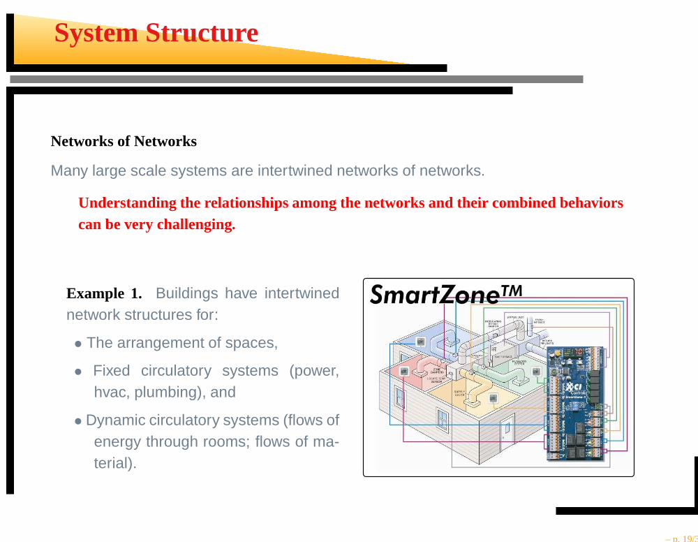
Networks of Networks
Many large scale systems are intertwined networks of networks.
Understanding the relationships among the networks and their combined behaviorscan be very challenging.
Example 1. Buildings have intertwinednetwork structures for:
• The arrangement of spaces,
• Fixed circulatory systems (power,hvac, plumbing), and
• Dynamic circulatory systems (flows ofenergy through rooms; flows of ma-terial).
– p. 19/31
System Structure
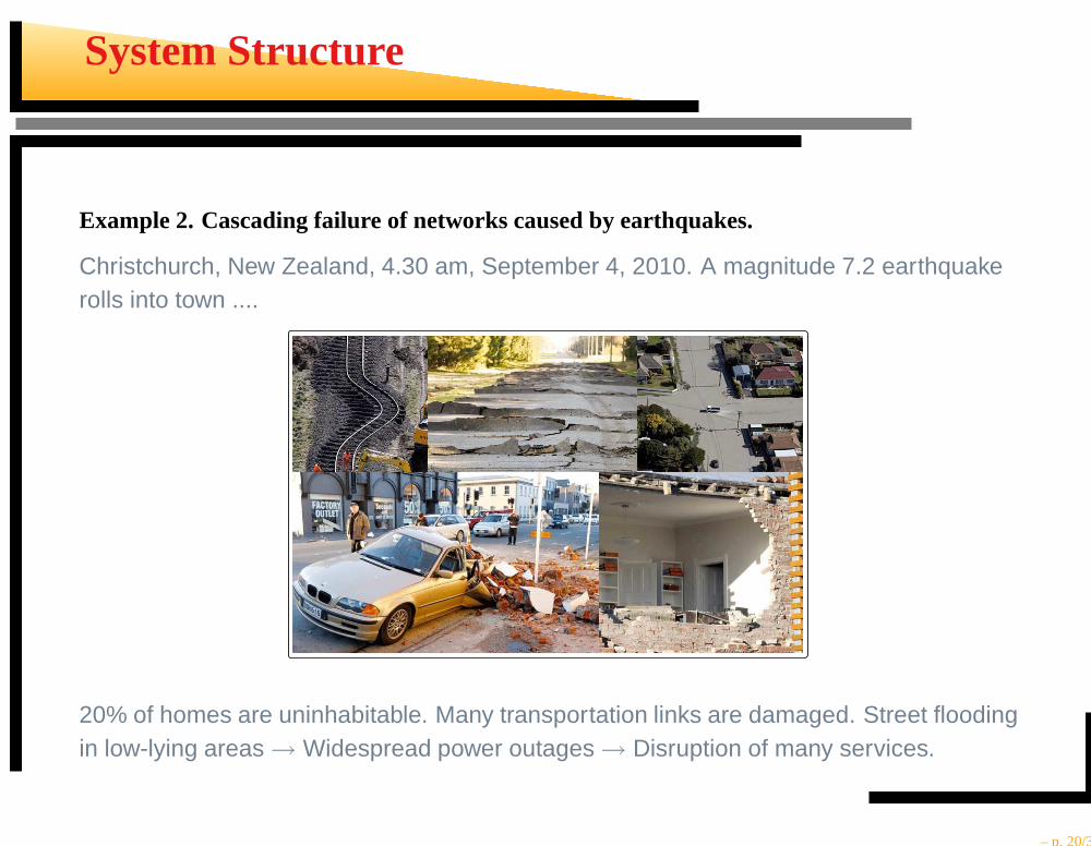
Example 2. Cascading failure of networks caused by earthquakes.
Christchurch, New Zealand, 4.30 am, September 4, 2010. A magnitude 7.2 earthquakerolls into town ....
20% of homes are uninhabitable. Many transportation links are damaged. Street floodingin low-lying areas → Widespread power outages → Disruption of many services.
– p. 20/31

System Structure
Planning for disaster relief needs to look at the connections between network models.
Basic questions:
• What kinds of dependenciesexist between the networks?
• How will a failure in onenetwork impact other net-works?
• What parts of a system aremost vulnerable?
• Does it make sense to stock-pile supplies of water andfood?
• How much should we spendto prepare for an inevitableattack?
Services
Waterway Network
Transportation Network
Information andCommunications
Emergency
– p. 21/31
Transformational Systems
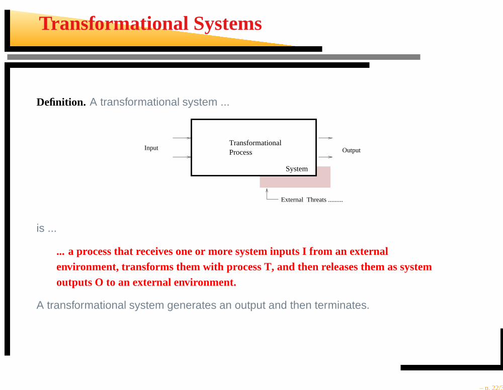
Definition. A transformational system ...
OutputInput
External Threats .........
System
TransformationalProcess
is ...
... a process that receives one or more system inputs I from anexternalenvironment, transforms them with process T, and then releases them as systemoutputs O to an external environment.
A transformational system generates an output and then terminates.
– p. 22/31

Transformational Systems
Classification: Single Input/Single Output (SISO)
Input OutputTransformational Process
Classification: Multiple Input/Multiple Output (MIMO)
Transformational Process
Input 1
Output 2
Output 1
Input 2
– p. 23/31

Reactive Systems
A reactive system is ...
... a system that, when turned on, is able to create desired effects in its environmentby enabling, enforcing, or preventing events in the environment.
time
A Reactive
System
Reactive systems are involved in a continuous interaction with the environment. Theenvironment:
... generates input events at discrete intervals through one or more interfaces andthe system reacts by changing its state and possibly generating output events.
– p. 24/31

Reactive Systems
Typical Classifications
Many reactive systems are:
• Real-time systems
A real-time system is a system in which the correctness of a response depends onthe logical correctness and time at which the response is produced.
• Safety-critical
Malfunctioning of the system could lead to a loss of life or property.
• Embedded systems
Software to support a real-time system is often embedded within the systemhardware.
• Control systems
Control systems enforce a desirable behavior on their environment.
– p. 25/31

Reactive Systems
Key Characteristics
• They have behavior defined by continuous, non-terminating, interaction with thesurrounding environment.
• If the system terminates during its availability time, then usually this is considered afailure.
• Reactive systems are required to respond to external stimulli as and when they occur.Therefore, reactive systems must be able to respond to interrupts, even when theyare doing something else.
• It follows that behavior of a reactive system is often defined by a set of interactingprocesses that operate in parallel.
• Often, reactive systems will need to operate in real time, and be subject to real-timeconstraints.
– p. 26/31

Reactive and Transformational Systems
Side-by-Side Comparison(Adapted from Wieringa, 2003)
Transformational System Reactive SystemMay interact to capture more data. Highly interactive.
Terminating process. Non-terminating process.
Non-interupt driven. Interrupt driven.
Output not state dependent. State-dependent response.
Output not defined in terms of the environ-ment.
Environment-oriented response.
Sequential process. Parallel processes.
Usually, no stringent time requirements. Usually, stringent time require-ments.
– p. 27/31

System Engineering View of Modeling
Systems engineers are ..
... the keepers of the processes, methods and tools needed toestablish and maintaina shared vision of the system problem definition and solution.
This process is complicated by the
• technical,
• social,
• regulatory, and financial aspects
of a complex design being too broad and detailed for a single individual to master.Hence, by necessity,
... system development is a team activity involving multiple stakeholders, theirdesign concerns, viewpoints, and ways of doing things.
– p. 28/31

System Engineering View of Modeling
Pathway from Functions to Representations in Multiple-Stakeholder Design
Models of System Behavior, System Structure,
Domain 1
Domain 2
Domain 3
RequirementsPreliminary
Team 1 Team 2 Team 3
Use cases and scenariosTeam−based DevelopmentIntegrate and Organize Requirements into Layers for
System Architecture ..... etc.....
– p. 29/31

System Engineering View of Modeling
Networks of Processes and Models in Systems Engineering
Customers / Users
Project LevelOrganizational Level
Organization RequirementsEngineeringSystem
Model ofEngineeringSystem
Model ofRequirements
Model ofOrganization
REAL WORLD SPACE
MODELING SPACE
Data Sol’ns Data Sol’ns
– p. 30/31

System Engineering View of Modeling
Systems Engineering Modeling and Process Requirements
Requirements
BehaviorCost
MaintenanceAssembly
Retirement
Customers / Users
ProjectOrganization
ManagementValidation / VerificationTraceabilityAllocation / Flowdown
OrganizationEvaluation
−− Legal agreementOrganization
EngineeringSystem
StrategyBusinesss processesResoucrcesStaff
CaptureRepresentation
MODELING SPACE
Data DataSol’ns Sol’nsREAL WORLD SPACE
– p. 31/31