four-row linear recirculating ball bearing and guideway ... linear recirculating ball... · except...
TRANSCRIPT
Market Information MAI 91
Quad spacers
for quiet ru
nning
Full complement
for maxim
um load capacity
Four-row linear recirculating ball bearing and guideway assemblieswith quad spacers or full complement
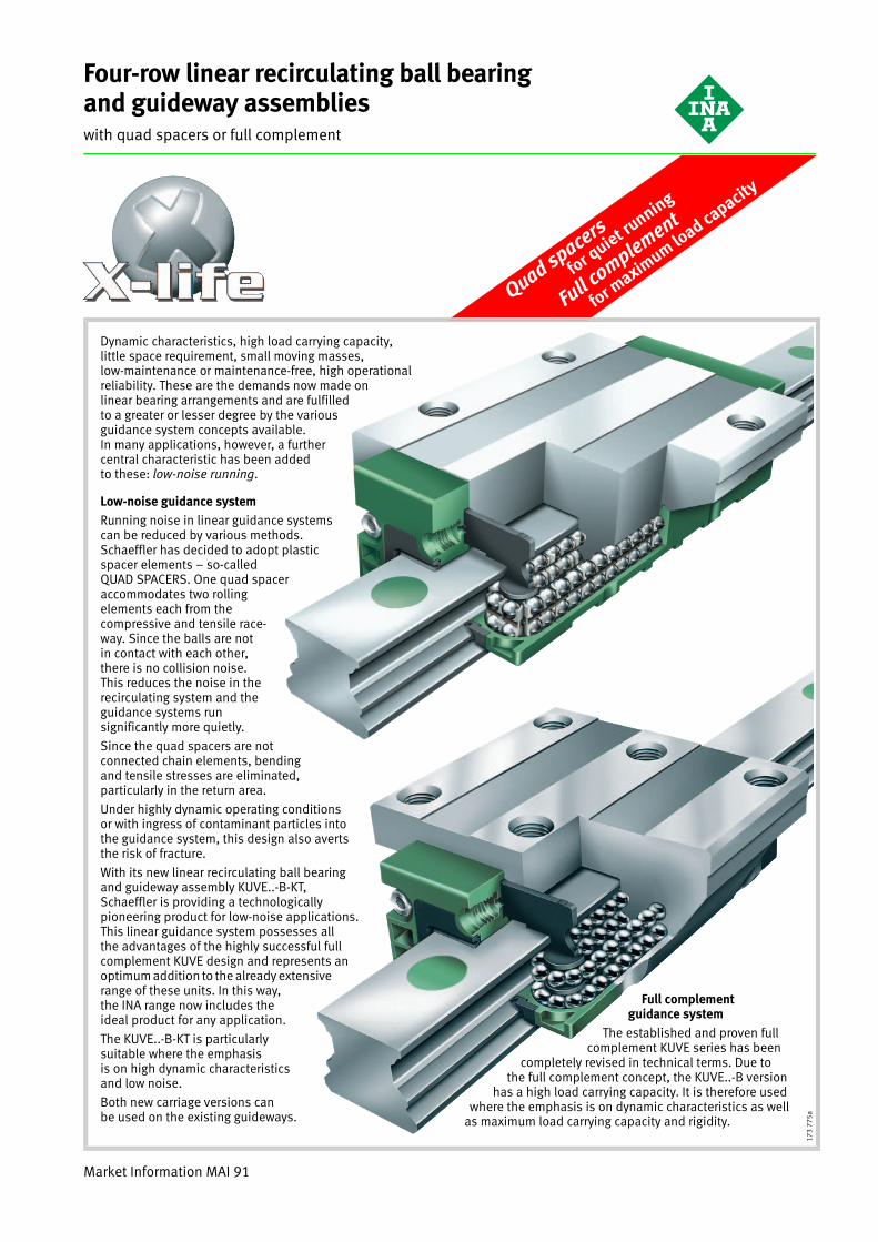
Dynamic characteristics, high load carrying capacity, little space requirement, small moving masses, low-maintenance or maintenance-free, high operational reliability. These are the demands now made on linear bearing arrangements and are fulfilled to a greater or lesser degree by the various guidance system concepts available. In many applications, however, a further central characteristic has been added to these: low-noise running.
Low-noise guidance systemRunning noise in linear guidance systems can be reduced by various methods. Schaeffler has decided to adopt plastic spacer elements – so-called QUAD SPACERS. One quad spacer accommodates two rolling elements each from the compressive and tensile race-way. Since the balls are not in contact with each other, there is no collision noise. This reduces the noise in the recirculating system and the guidance systems run significantly more quietly.
Since the quad spacers are not connected chain elements, bending and tensile stresses are eliminated, particularly in the return area.
Under highly dynamic operating conditions or with ingress of contaminant particles into the guidance system, this design also averts the risk of fracture.
With its new linear recirculating ball bearing and guideway assembly KUVE..-B-KT, Schaeffler is providing a technologically pioneering product for low-noise applications. This linear guidance system possesses all the advantages of the highly successful full complement KUVE design and represents an optimum addition to the already extensive range of these units. In this way, the INA range now includes the ideal product for any application.
The KUVE..-B-KT is particularly suitable where the emphasis is on high dynamic characteristics and low noise.
Both new carriage versions can be used on the existing guideways.
173
775a
Full complement guidance system
The established and proven full complement KUVE series has been
completely revised in technical terms. Due to the full complement concept, the KUVE..-B version
has a high load carrying capacity. It is therefore used where the emphasis is on dynamic characteristics as well
as maximum load carrying capacity and rigidity.
2
Four-row linear recirculating ball bearing and guideway assemblieswith quad spacers
Page
Preload................................................................ 28
Friction ................................................................. 28
Accuracy ............................................................... 29
Demands on the adjacent construction ................. 32
Ordering example and ordering designation ......... 6
Features
Four-row linear recirculating ball bearing and guideway assemblies■ are complete units comprising:
– at least one carriage KWVE..-B-KT– a guideway TKVD, TKVD..-U, TKVD..-ZHP or TKVD..-K
with two locating edges in each case– plastic spacer elements to guide the rolling elements– integral elastic wipers and sealing strips on the end
faces and longitudinal faces of the carriage– two-piece plastic closing plugs
■ run with less noise than full complement designs
■ can support loads from all directions – apart from the direction of motion – and moments about all axes
■ are preloaded– the preload is determined by the carriage
■ are lubricated via the lubrication nipple in the end piece (on the end face or from the side) with grease or oil– the end face lubrication nipple is included in the delivery– the lubrication nipple for relubrication from the side
is available by agreement
■ are based on a modular concept (see also Interchangeability, page 4)– guideways can be combined with all carriage types
within one size– can be ordered separately as a carriage KWVE..-B-KT and
guideway TKVD or as a unit KUVE..-B-KT. In a unit, one or more carriages can be mounted on a guideway
■ are suitable for:– accelerations up to 150 m/s2
– speeds up to 360 m/min1)
– operating temperatures from –10 °C to +100 °C
■ can also be supplied with multi-piece guideways– see Multi-piece guideways, page 31
■ are used in applications with:– long, unlimited stroke lengths– high dynamic characteristics– high running and positional accuracy– low friction– low noise levels.
1) For speeds �180 m/min, please consult us.
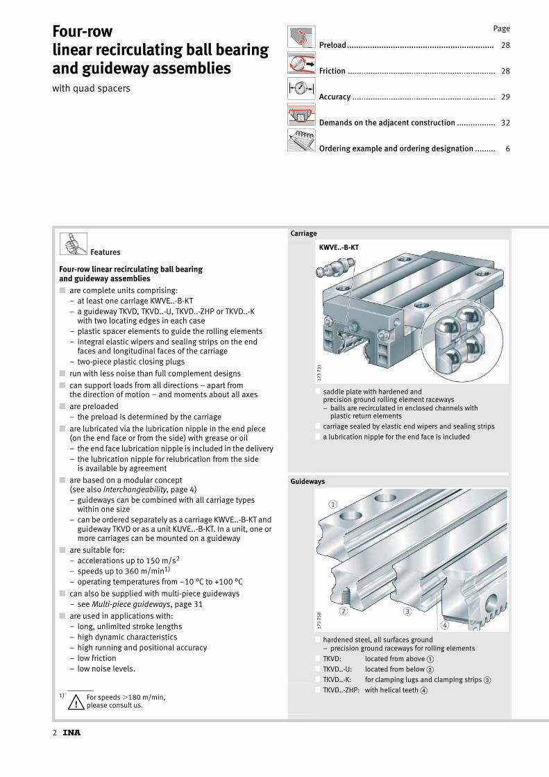
Carriage
■ saddle plate with hardened and precision ground rolling element raceways– balls are recirculated in enclosed channels with
plastic return elements■ carriage sealed by elastic end wipers and sealing strips
■ a lubrication nipple for the end face is included
Guideways
■ hardened steel, all surfaces ground– precision ground raceways for rolling elements
■ TKVD: located from above �
■ TKVD..-U: located from below �■ TKVD..-K: for clamping lugs and clamping strips �
■ TKVD..-ZHP: with helical teeth �
KWVE..-B-KT
173
731
173
758
3
KUVE..-B-KT
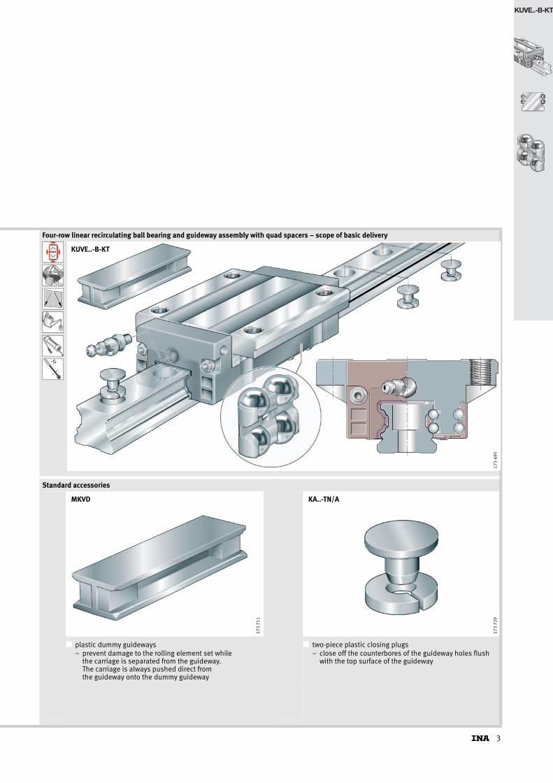
Four-row linear recirculating ball bearing and guideway assembly with quad spacers – scope of basic delivery
k0M
˚C
■ ■Standard accessories
■ plastic dummy guideways– prevent damage to the rolling element set while
the carriage is separated from the guideway. The carriage is always pushed direct from the guideway onto the dummy guideway
■ two-piece plastic closing plugs– close off the counterbores of the guideway holes flush
with the top surface of the guideway
KUVE..-B-KT
173
695
173
711
MKVD17
3 72
9KA..-TN/A

4
Four-row linear recirculating ball bearing and guideway assemblieswith quad spacers
Design of carriagesThe rows of balls run in a steel saddle plate with hardened and ground raceways at a contact angle of 45° in an O arrangement.
In order to prevent noise from recirculation, the rolling elements are guided in plastic spacer units called “quad spacers”. The balls are recirculated in enclosed channels with plastic return elements.
InterchangeabilityThe guideways and carriages can be freely interchanged and combined with each other (see page 5).
This means:■ more economical stockholding
■ simpler fitting
■ quicker sourcing of replacement parts
■ the option of achieving several preload classes on one guideway, since the preload class is determined by the carriage
■ versatile design possibilities for KUVE guidance systems using standard elements.
Corrosion-resistant designsKUVE..-B-KT is also available with the Corrotect® plating.
If carriages and guideways are ordered separately, the following applies:■ carriage and guideway with anti-corrosion protection:
– suffix RRF.
If units are supplied preassembled, there are two variants:■ carriage and guideway with anti-corrosion protection
– suffix RRF
■ guideway only with anti-corrosion protection– suffix RRFT.
Lubricant reservoir, sealingDue to the integral lubricant reservoir �, the linear ball bearing and guideway assemblies have long relubrication intervals; depending on the application, they may even be maintenance-free.
Standard sealing strips � as well as additional sealing strips (optional) � ensure effective sealing.
These sealing elements protect the rolling element system from contamination even under demanding environmental conditions.
Contact angle, quad spacers
■ quad spacers (plastic spacer elements)
■ contact angles of the four rows of balls
■ rows of balls in two point contact with raceways
Lubricant reservoir, sealing
■ integral lubricant pockets with grease reservoir �
■ standard sealing strip �
■ optional sealing strip �
■ elastic wipers on end faces �
45˚
173
733
4
3
1
2
KUVE..-B-KT17
3 69
7

5
KUVE..-B-KT
KWVE..-B-KT-S
KWVE..-B-KT-SL
KWVE..-B-KT-H
KWVE..-B-KT-HLTKVD
TKVD..-K
TKVD..-ZHP
TKVD..-U
KWVE..-B-KT
KWVE..-B-KT-L
173
735

6
Four-row linear recirculating ball bearing and guideway assemblieswith quad spacers
Ordering example and ordering designation
Ordering example 1Linear recirculating ball bearing and guideway assembly KUVE..-B-KT, asymmetrical hole pattern
Ordering designation:1�KUVE25-B-KT-W2-G3-V2-RRFT/1510-50/20 (Figure 1).
Figure 1 · Ordering example, ordering designation
Four-row ball bearing and guideway assembly KUVESize 25Version with plastic spacer elements B-KTNumber of carriages per unit W2Accuracy class G3Carriage preload V2Guideway with Corrotect® plating RRFTGuideway length 1510 mm– aL– aR
20 mm50 mm
KUVE25-B-KT-W2-G3-V2-RRFT/1510-50/20
2525
50
20
1510
1�
173
740

7
KUVE..-B-KT
Ordering example 2Linear recirculating ball bearing and guideway assembly KUVE..-B-KT, carriage and guideway separate, symmetrical hole pattern
Ordering designation:2�KWVE25-B-KT-L-G3-V2 (Figure 2).
Ordering designation:1�TKVD25/1570-35/35 (Figure 2).
Figure 2 · Ordering example, ordering designation
CarriageCarriage KWVESize 25Version with plastic spacer elements B-KTCarriage variant LAccuracy class G3Carriage preload V2
GuidewayGuideway for carriage TKVDSize 25Guideway length 1570 mm– aL– aR
35 mm35 mm
25
35
35
1570
2�
TKVD25/1570-35/351�
KWVE25-B-KT-L-G3-V2
173
741

8
Four-row linear recirculating ball bearing and guideway assemblieswith quad spacers
Series KUVE..-B-KTKUVE..-B-KT-L
TKVD..-U
h t
G
b
7
1 a j
l
L L
max
aR
172
338
1) Maximum length of single-piece guideways; longer guideways are supplied in several sections and are marked accordingly. Maximum single-piece guideway length of 6 m by agreement.
2) aL and aR are dependent on the guideway length, Calculation, page 31.3) If there is a possibility of settling, the fixing screws should be secured against rotation.4) For information on fixing screws see INA Catalogue “605”, Fixing screws.5) Calculation of basic load ratings in accordance with DIN 636.
Based on practical experience, it may be possible to increase the basic dynamic load rating.6) Lubrication nipple with tapered head to DIN 71412-B M6,
except for KUVE20-B-KT to DIN 71412-B M5 and KUVE15-B-KT to DIN 3 405 M3.7) The new carriages cannot be used on the existing guideways TKVD15(-U).
Dimension table · Dimensions in mm
Unit Carriage Guideway Dimensions
Designation Designation Mass Designation Mass Closing plug lmax1) H B L
m m K2
�kg �kg/m
KUVE15-B-KT KWVE15-B-KT 0,17TKVD15-B(-U)7) 1,44 KA07-TN/A 1200 24 47
59,6
KUVE15-B-KT-L KWVE15-B-KT-L 0,21 73
KUVE20-B-KT KWVE20-B-KT 0,38TKVD20(-U) 2,2 KA10-TN/A 1980 30 63
69,8
KUVE20-B-KT-L KWVE20-B-KT-L 0,5 87,3
KUVE25-B-KT KWVE25-B-KT 0,5TKVD25(-U) 2,7 KA11-TN/A 1980 36 70
82,1
KUVE25-B-KT-L KWVE25-B-KT-L 0,62 107,9
Lateral lubrication connector
A 4
�N3
JL6
205
089
Dimensioning of lateral lubrication connector
Designation �N3 A4 JL6
KUVE15-B-KT 2,7 3,2 9,1
KUVE15-B-KT-L 2,7 3,2 15,8
KUVE20-B-KT 4,7 4,5 9,5
KUVE20-B-KT-L 4,7 4,5 18,3
KUVE25-B-KT 5,6 6,5 12,9
KUVE25-B-KT-L 5,6 6,5 25,8

9
KUVE..-B-KT
KUVE..-B-KT(-L) KUVE..-B-KT(-L) · View X (rotated 90°)
Ab 1
H
TH
h
55
JB
ADIN 71412-B M6 2
B
6)
X
Hh
A3
1 1
G2
K3
Locating faceMarking
173
683
L1
K1
jL aR
l
JL
L4
aL
A L1
max
Locating face
Marking
173
684
Mounting dimensions Fixing screws3)4)
A1 JB b–0,005–0,03
A2 L1 JL jL aL/aR2) AL1 H1 H5 A3 T5 t7 h h1 G1 G2 K1 K3
ISO 4 762-12.9
min. max.
16 38 15 4,539,8
30 60 20 53 6,7 4,5 4,75 4 7 8 15 8,15 M5 M5 M4 M453,2
21,5 53 20 550,4
40 60 20 53 19 4,5 5,25 8 7,5 10 17 9,1 M6 M6 M5 M567,9
23,5 57 23 6,560,7
45 60 20 53 19 5,5 5,25 11 10 12 18,7 8,7 M6 M8 M6 M686,5
Load directions
Load carrying capacity (for definition of basic load ratings, see INA Catalogue “605”)5)
UnitDesignation
Basic load ratings Moment ratings
CN
C0N
M0xNm
M0yNm
M0zNm
KUVE15-B-KT 6 100 11 400 105 74 53
KUVE15-B-KT-L 7 500 15 500 162 148 105
KUVE20-B-KT 11 800 23 000 253 130 127
KUVE20-B-KT-L 14 400 30 500 335 225 225
KUVE25-B-KT 16 200 32 000 370 210 200
KUVE25-B-KT-L 21 100 47 000 535 430 410
M
M
x
y
zM0y
0z
C, C0
C, C 00x
173
685
10
Four-row linear recirculating ball bearing and guideway assemblieswith quad spacers
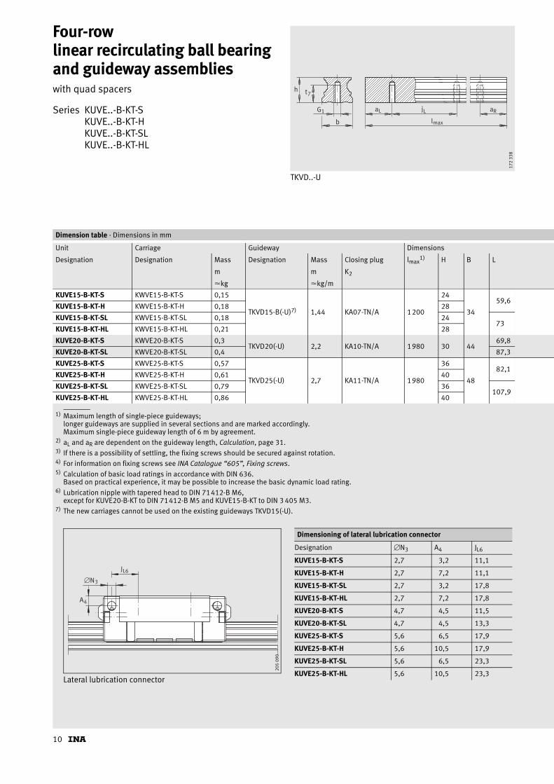
Series KUVE..-B-KT-SKUVE..-B-KT-HKUVE..-B-KT-SLKUVE..-B-KT-HL
TKVD..-U
h t
G
b
7
1 a j
l
L L
max
aR
172
338
1) Maximum length of single-piece guideways; longer guideways are supplied in several sections and are marked accordingly. Maximum single-piece guideway length of 6 m by agreement.
2) aL and aR are dependent on the guideway length, Calculation, page 31.3) If there is a possibility of settling, the fixing screws should be secured against rotation.4) For information on fixing screws see INA Catalogue “605”, Fixing screws.5) Calculation of basic load ratings in accordance with DIN 636.
Based on practical experience, it may be possible to increase the basic dynamic load rating.6) Lubrication nipple with tapered head to DIN 71412-B M6,
except for KUVE20-B-KT to DIN 71412-B M5 and KUVE15-B-KT to DIN 3 405 M3.7) The new carriages cannot be used on the existing guideways TKVD15(-U).
Dimension table · Dimensions in mm
Unit Carriage Guideway Dimensions
Designation Designation Mass Designation Mass Closing plug lmax1) H B L
m m K2
�kg �kg/m
KUVE15-B-KT-S KWVE15-B-KT-S 0,15
TKVD15-B(-U)7) 1,44 KA07-TN/A 1200
24
34
59,6KUVE15-B-KT-H KWVE15-B-KT-H 0,18 28
KUVE15-B-KT-SL KWVE15-B-KT-SL 0,18 2473
KUVE15-B-KT-HL KWVE15-B-KT-HL 0,21 28
KUVE20-B-KT-S KWVE20-B-KT-S 0,3TKVD20(-U) 2,2 KA10-TN/A 1980 30 44
69,8
KUVE20-B-KT-SL KWVE20-B-KT-SL 0,4 87,3
KUVE25-B-KT-S KWVE25-B-KT-S 0,57
TKVD25(-U) 2,7 KA11-TN/A 1980
36
48
82,1KUVE25-B-KT-H KWVE25-B-KT-H 0,61 40
KUVE25-B-KT-SL KWVE25-B-KT-SL 0,79 36107,9
KUVE25-B-KT-HL KWVE25-B-KT-HL 0,86 40
Lateral lubrication connector
A4
JL6
�N3
205
090
Dimensioning of lateral lubrication connector
Designation �N3 A4 JL6
KUVE15-B-KT-S 2,7 3,2 11,1
KUVE15-B-KT-H 2,7 7,2 11,1
KUVE15-B-KT-SL 2,7 3,2 17,8
KUVE15-B-KT-HL 2,7 7,2 17,8
KUVE20-B-KT-S 4,7 4,5 11,5
KUVE20-B-KT-SL 4,7 4,5 13,3
KUVE25-B-KT-S 5,6 6,5 17,9
KUVE25-B-KT-H 5,6 10,5 17,9
KUVE25-B-KT-SL 5,6 6,5 23,3
KUVE25-B-KT-HL 5,6 10,5 23,3

11
KUVE..-B-KT
KUVE..-B-KT(-S, -H, -SL, -HL) KUVE..-B-KT(-S, -H, -SL, -HL) · View X (rotated 90°)
Ab 1
H
TH
h
55
J
B
ADIN 71412-B M6 2
B
6)
X
Hh
A3
11
G2
Locating faceMarking
173
688
L1
K1
jL aR
lJL
L4
aL
max
AL1
Locating face
Marking
173
689
Mounting dimensions Fixing screws3)4)
A1 JB b–0,005–0,03
A2 L1 JL jL aL/aR2) AL1 H1 H5 A3 T5 t7 h h1 G1 G2 K1
ISO 4 762-12.9
min. max.
9,5 26 15 4
39,8
26 60 20 53 6,7 4,5 4,75
4
7 8 15 8,15 M5 M4 M48
53,24
8
12 32 20 650,4 36
60 20 53 19 4,5 5,25 8 7,5 10 17 9,1 M6 M5 M567,9 50
12,5 35 23 6,5
60,7 35
60 20 53 19 5,1 5,25
11
10 12 18,7 8,7 M6 M6 M615
86,5 5011
15
Load directions
Load carrying capacity (for definition of basic load ratings, see INA Catalogue “605”)5)
UnitDesignation
Basic load ratings Moment ratings
CN
C0N
M0xNm
M0yNm
M0zNm
KUVE15-B-KT-S 6 100 11 400 105 82 53
KUVE15-B-KT-H 6 100 11 400 105 82 53
KUVE15-B-KT-SL 7 500 15 500 162 148 105
KUVE15-B-KT-HL 7 500 15 500 162 148 105
KUVE20-B-KT-S 11 800 23 000 253 130 127
KUVE20-B-KT-SL 14 400 30 500 335 225 225
KUVE25-B-KT-S 16 200 32 000 370 210 200
KUVE25-B-KT-H 16 200 32 000 370 210 200
KUVE25-B-KT-SL 21 100 47 000 535 430 410
KUVE25-B-KT-HL 21 100 47 000 535 430 410
M
M
x
y
zM0y
0z
C, C 0
C, C0
0x
173
690
12
Four-row linear recirculating ball bearing and guideway assembliesfull complement
Page
Preload................................................................ 28
Friction ................................................................. 28
Accuracy ............................................................... 29
Demands on the adjacent construction ................. 32
Ordering example and ordering designation ......... 16
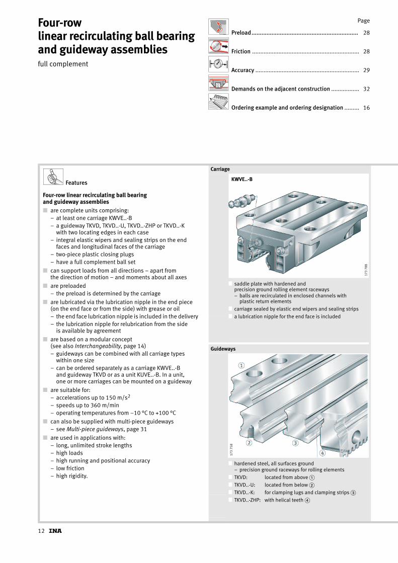
Features
Four-row linear recirculating ball bearing and guideway assemblies■ are complete units comprising:
– at least one carriage KWVE..-B– a guideway TKVD, TKVD..-U, TKVD..-ZHP or TKVD..-K
with two locating edges in each case– integral elastic wipers and sealing strips on the end
faces and longitudinal faces of the carriage– two-piece plastic closing plugs– have a full complement ball set
■ can support loads from all directions – apart from the direction of motion – and moments about all axes
■ are preloaded– the preload is determined by the carriage
■ are lubricated via the lubrication nipple in the end piece (on the end face or from the side) with grease or oil– the end face lubrication nipple is included in the delivery– the lubrication nipple for relubrication from the side
is available by agreement
■ are based on a modular concept (see also Interchangeability, page 14)– guideways can be combined with all carriage types
within one size– can be ordered separately as a carriage KWVE..-B
and guideway TKVD or as a unit KUVE..-B. In a unit, one or more carriages can be mounted on a guideway
■ are suitable for:– accelerations up to 150 m/s2
– speeds up to 360 m/min– operating temperatures from –10 °C to +100 °C
■ can also be supplied with multi-piece guideways– see Multi-piece guideways, page 31
■ are used in applications with:– long, unlimited stroke lengths– high loads– high running and positional accuracy– low friction– high rigidity.
Carriage
■ saddle plate with hardened and precision ground rolling element raceways– balls are recirculated in enclosed channels with
plastic return elements■ carriage sealed by elastic end wipers and sealing strips
■ a lubrication nipple for the end face is included
Guideways
■ hardened steel, all surfaces ground– precision ground raceways for rolling elements
■ TKVD: located from above �
■ TKVD..-U: located from below �■ TKVD..-K: for clamping lugs and clamping strips �
■ TKVD..-ZHP: with helical teeth �
KWVE..-B
173
788
173
758

13
KUVE..-B
Four-row linear recirculating ball bearing and guideway assembly, full complement – scope of basic delivery
k0M
˚C
■ ■Standard accessories
■ plastic dummy guideways– prevent damage to the rolling element set while
the carriage is separated from the guideway. The carriage is always pushed direct from the guideway onto the dummy guideway
■ two-piece plastic closing plugs– close off the counterbores of the guideway holes flush
with the top surface of the guideway
KUVE..-B
173
789
173
711
MKVD17
3 72
9KA..-TN/A

14
Four-row linear recirculating ball bearing and guideway assembliesfull complement
Design of carriagesThe rows of balls run in a steel saddle plate with hardened and ground raceways at a contact angle of 45° in an O arrangement.
The full complement ball set is recirculated through channels in the steel saddle plate.
InterchangeabilityThe carriages and guideways can be freely interchanged and combined with each other.
This means:■ more economical stockholding
■ simpler fitting
■ quicker sourcing of replacement parts
■ the option of achieving several preload classes on one guideway, since the preload class is determined by the carriage
■ versatile design possibilities for KUVE guidance systems using standard elements.
Corrosion-resistant designsKUVE..-B is also available with the Corrotect® plating.
If carriages and guideways are ordered separately, the following applies:■ carriage and guideway with anti-corrosion protection:
– suffix RRF.
If units are supplied preassembled, there are two variants:■ carriage and guideway with anti-corrosion protection
– suffix RRF
■ guideway only with anti-corrosion protection– suffix RRFT.
Lubricant reservoir, sealingDue to the integral lubricant reservoir �, the linear ball bearing and guideway assemblies have long relubrication intervals; depending on the application, they may even be maintenance-free.
Standard sealing strips � as well as additional sealing strips (optional) � ensure effective sealing.
These sealing elements protect the rolling element system from contamination even under demanding environmental conditions.
Contact angle
■ contact angles of the four rows of balls
■ rows of balls in two point contact with raceways
Lubricant reservoir, sealing
■ integral lubricant pockets with grease reservoir �
■ standard sealing strip �
■ optional sealing strip �
■ elastic wipers on end faces �
45˚
45˚
173
178
3
1
2
4
KUVE..-B17
3 79
5

15
KUVE..-B
TKVD
TKVD..-K
TKVD..-ZHP
TKVD..-U
KWVE..-B-S
KWVE..-B KWVE..-B-N
KWVE..-B-EC
KWVE..-B-ESC
KWVE..-B-SN
KWVE..-B-HL
KWVE..-B-LKWVE..-B-NL
KWVE..-B-H
KWVE..-B-SL
KWVE..-B-SNL
205
091
16
Four-row linear recirculating ball bearing and guideway assembliesfull complement
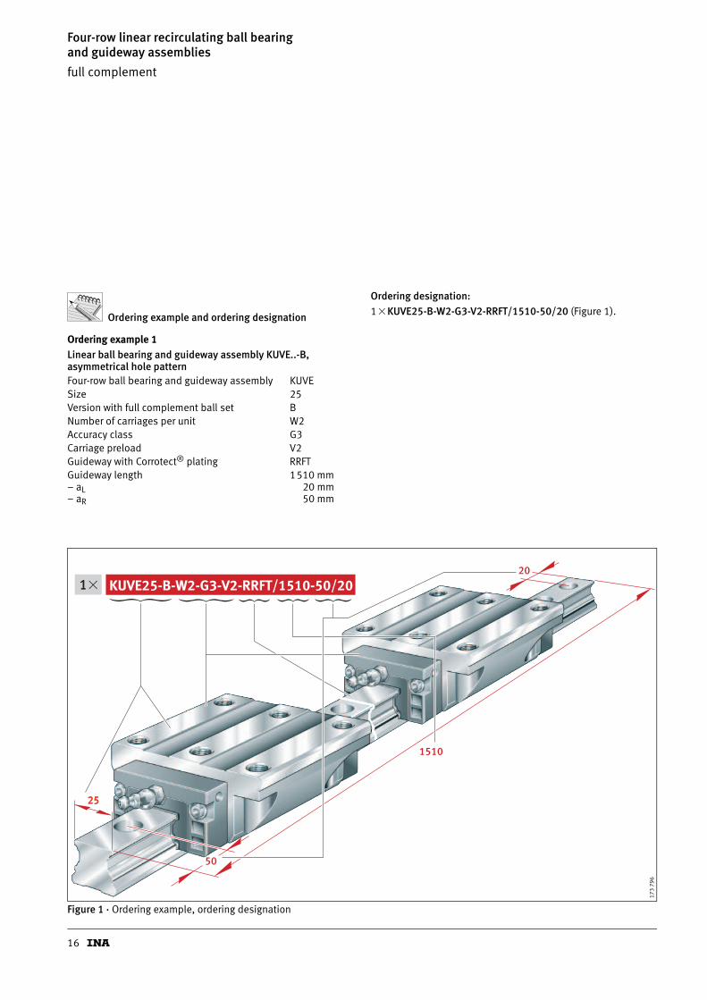
Ordering example and ordering designation
Ordering example 1Linear ball bearing and guideway assembly KUVE..-B, asymmetrical hole pattern
Ordering designation:1�KUVE25-B-W2-G3-V2-RRFT/1510-50/20 (Figure 1).
Figure 1 · Ordering example, ordering designation
Four-row ball bearing and guideway assembly KUVESize 25Version with full complement ball set BNumber of carriages per unit W2Accuracy class G3Carriage preload V2Guideway with Corrotect® plating RRFTGuideway length 1510 mm– aL– aR
20 mm50 mm
KUVE25-B-W2-G3-V2-RRFT/1510-50/20
50
20
1510
2525
1�
173
796
17
KUVE..-B
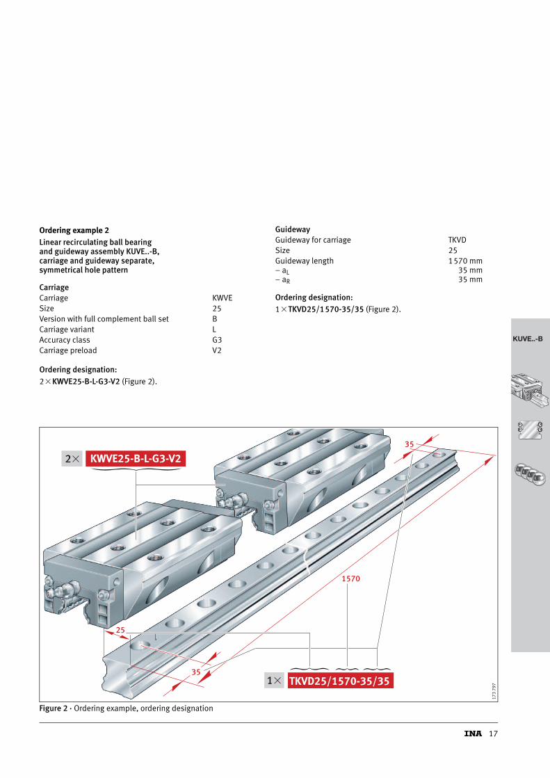
Ordering example 2Linear recirculating ball bearing and guideway assembly KUVE..-B, carriage and guideway separate, symmetrical hole pattern
Ordering designation:2�KWVE25-B-L-G3-V2 (Figure 2).
Ordering designation:1�TKVD25/1570-35/35 (Figure 2).
Figure 2 · Ordering example, ordering designation
CarriageCarriage KWVESize 25Version with full complement ball set BCarriage variant LAccuracy class G3Carriage preload V2
GuidewayGuideway for carriage TKVDSize 25Guideway length 1570 mm– aL– aR
35 mm35 mm
35
35
1570
KWVE25-B-L-G3-V22�
TKVD25/1570-35/35 1�
25
173
797

18
Four-row linear recirculating ball bearing and guideway assembliesfull complement
Series KUVE..-BKUVE..-B-LKUVE..-B-NKUVE..-B-NL
TKVD..-U
h t
G
b
7
1 a j
l
L L
max
aR
172
338
1) Maximum length of single-piece guideways; longer guideways are supplied in several sections and are marked accordingly. Maximum single-piece guideway length of 6 m by agreement.
2) aL and aR are dependent on the guideway length, Calculation, page 31.3) If there is a possibility of settling, the fixing screws should be secured against rotation.4) For information on fixing screws see INA Catalogue “605”, Fixing screws.5) Calculation of basic load ratings in accordance with DIN 636.
Based on practical experience, it may be possible to increase the basic dynamic load rating.6) Lubrication nipple with tapered head to DIN 71412-B M6,
except for KUVE20-B to DIN 71412-B M5 and KUVE15-B to DIN 3 405 M3.7) The new carriages cannot be used on the existing guideways TKVD15(-U).
Dimension table · Dimensions in mm
Unit Carriage Guideway Dimensions Mounting dimensions
Designation Designation Mass Designation Mass Closing plug lmax1) H B L A1 JB b
–0,005–0,03
A2
m m K2
�kg �kg/m
KUVE15-B KWVE15-B 0,25 TKVD15-B(-U)7) 1,44 KA07-TN/A 1200 24 47 59,6 16 38 15 4,5
KUVE20-B KWVE20-B 0,58
TKVD20(-U) 2,2 KA10-TN/A 1980
30
63
69,8
21,5 53 20 5KUVE20-B-L KWVE20-B-L 0,8 87,3
KUVE20-B-N KWVE20-B-N 0,4727
69,8
KUVE20-B-NL KWVE20-B-NL 0,65 87,3
KUVE25-B KWVE25-B 0,71
TKVD25(-U) 2,7 KA11-TN/A 1980
36
70
81,7
23,5 57 23 6,5KUVE25-B-L KWVE25-B-L 1 107,5
KUVE25-B-N KWVE25-B-N 0,5731
81,7
KUVE25-B-NL KWVE25-B-NL 0,8 107,5
Lateral lubrication connector
JL6
A 4
�N3
205
088
Dimensioning of lateral lubrication connector
Designation �N3 A4 JL6
KUVE15-B 2,7 3,2 9,1
KUVE20-B 4,7 4,6 9,4
KUVE20-B-L 4,7 4,6 18,2
KUVE20-B-N 2,7 3,3 9,4
KUVE20-B-NL 2,7 3,3 18,2
KUVE25-B 5,6 6,5 12,9
KUVE25-B-L 5,6 6,5 25,8
KUVE25-B-N 2,7 4 12,1
KUVE25-B-NL 2,7 4 25

19
KUVE..-B
KUVE..-B(-L) KUVE..-B(-L) · View X (rotated 90°)
DIN 71412-A M6
Hh
A3
1 1
JB
AB
X
H
H
TH
h
455
Ab 1
T6
2
G2
K3
K6
6)
Marking Locating face
173
776
L1
JLZ
K1
jL aR
l
JL
L
G2
JB
4
aL
AL1
max
Marking
Locating face
173
790
Fixing screws3)4)
L1 JL JLZ jL aL/aR2) AL1 H1 H4 H5 A3 T5 T6 t7 h h1 G1 G2 K1 K3 K6 K6
ISO 4 762-12.9 DIN 7984-8.8
min. max.
39,8 30 26 60 20 53 6,7 4,5 7,6 4,75 4 7 5,8 8 15 8,15 M5 M5 M4 M4 – M4
50,4
40 35 60 20 53 19 4,5
11
5
8 10 7,5
10 17 9,1 M6 M6 M5 M5
M5 –67,9
50,48,6 5 8 6 – M5
67,9
60,7
45 40 60 20 53 19 5,4
10,9
5
11
10
10
12 18,7 8,7 M6 M8 M6 M6
M6 –86,5
60,79,3 6 8 – M6
86,5
Load direction
Load carrying capacity (for definition of basic load ratings, see INA Catalogue “605”)5)
UnitDesignation
Basic load ratings Moment ratings
CN
C0N
M0xNm
M0yNm
M0zNm
KUVE15-B 7 200 14 500 150 100 100
KUVE20-B 13 100 27 000 332 240 240
KUVE20-B-L 16 200 36 500 452 430 430
KUVE20-B-N 13 100 27 000 332 240 240
KUVE20-B-NL 16 200 36 500 452 430 430
KUVE25-B 17 900 37 000 510 395 395
KUVE25-B-L 23 400 54 000 745 825 825
KUVE25-B-N 17 900 37 000 510 395 395
KUVE25-B-NL 23 400 54 000 745 825 825
M
M
x
y
z
0x
M0y
0z
C, C 0
C, C 0
172
341
20
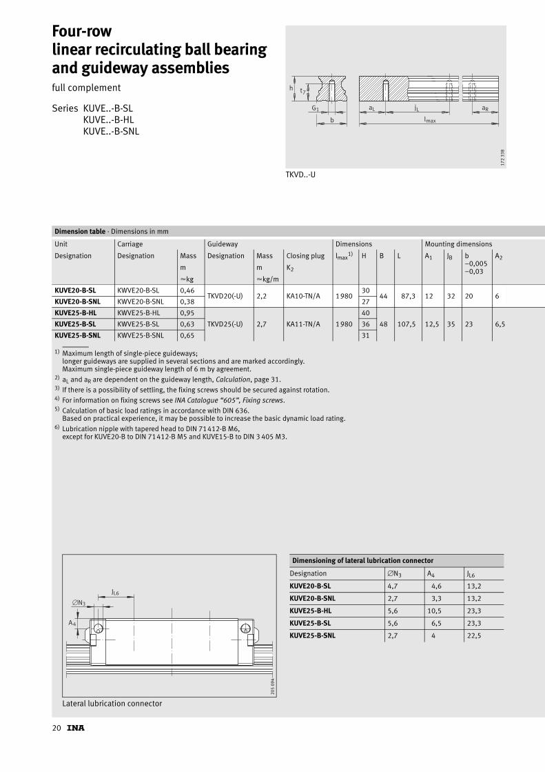
Four-row linear recirculating ball bearing and guideway assembliesfull complement
Series KUVE..-B-SLKUVE..-B-HLKUVE..-B-SNL
TKVD..-U
h t
G
b
7
1 a j
l
L L
max
aR
172
338
1) Maximum length of single-piece guideways; longer guideways are supplied in several sections and are marked accordingly. Maximum single-piece guideway length of 6 m by agreement.
2) aL and aR are dependent on the guideway length, Calculation, page 31.3) If there is a possibility of settling, the fixing screws should be secured against rotation.4) For information on fixing screws see INA Catalogue “605”, Fixing screws.5) Calculation of basic load ratings in accordance with DIN 636.
Based on practical experience, it may be possible to increase the basic dynamic load rating.6) Lubrication nipple with tapered head to DIN 71412-B M6,
except for KUVE20-B to DIN 71412-B M5 and KUVE15-B to DIN 3 405 M3.
Dimension table · Dimensions in mm
Unit Carriage Guideway Dimensions Mounting dimensions
Designation Designation Mass Designation Mass Closing plug lmax1) H B L A1 JB b
–0,005–0,03
A2
m m K2
�kg �kg/m
KUVE20-B-SL KWVE20-B-SL 0,46TKVD20(-U) 2,2 KA10-TN/A 1980
3044 87,3 12 32 20 6
KUVE20-B-SNL KWVE20-B-SNL 0,38 27
KUVE25-B-HL KWVE25-B-HL 0,95
TKVD25(-U) 2,7 KA11-TN/A 1980
40
48 107,5 12,5 35 23 6,5KUVE25-B-SL KWVE25-B-SL 0,63 36
KUVE25-B-SNL KWVE25-B-SNL 0,65 31
Lateral lubrication connector
A4
JL6
�N3
205
094
Dimensioning of lateral lubrication connector
Designation �N3 A4 JL6
KUVE20-B-SL 4,7 4,6 13,2
KUVE20-B-SNL 2,7 3,3 13,2
KUVE25-B-HL 5,6 10,5 23,3
KUVE25-B-SL 5,6 6,5 23,3
KUVE25-B-SNL 2,7 4 22,5
21
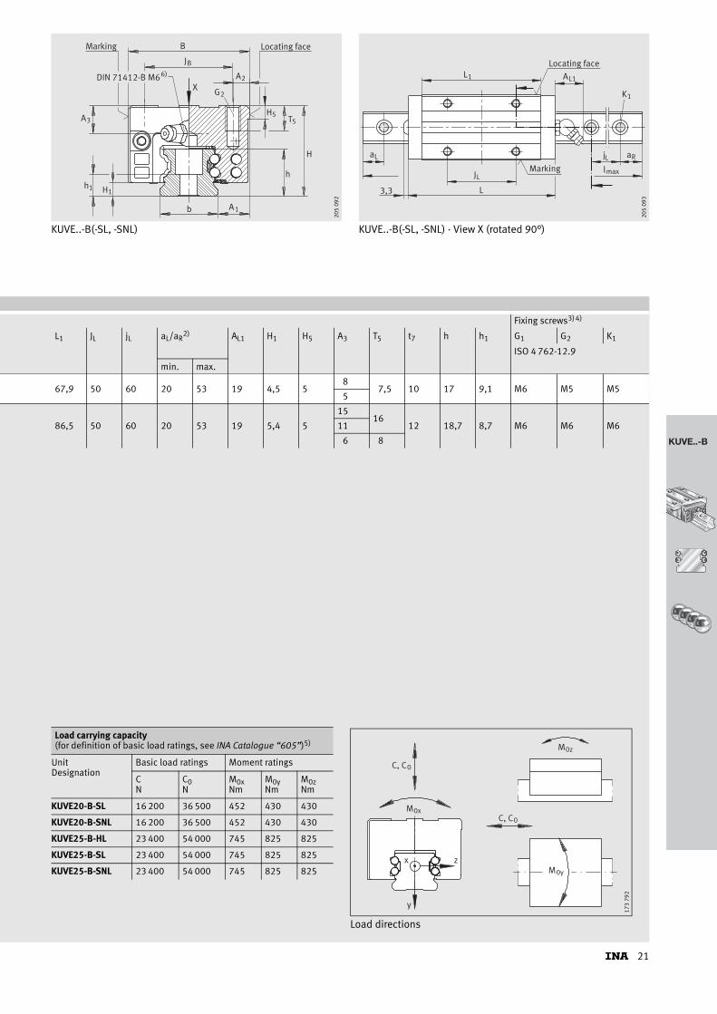
KUVE..-B
KUVE..-B(-SL, -SNL) KUVE..-B(-SL, -SNL) · View X (rotated 90°)
H
TH
h
55
J
B
B
Hh
A3
1 1
Ab 1
ADIN 71412-B M6 26)
X G2
Locating faceMarking
205
092
jL aR
lmax
aL
JL
L3,3
L1 AL1
K1
Marking
Locating face
205
093
Fixing screws3)4)
L1 JL jL aL/aR2) AL1 H1 H5 A3 T5 t7 h h1 G1 G2 K1
ISO 4 762-12.9
min. max.
67,9 50 60 20 53 19 4,5 58
7,5 10 17 9,1 M6 M5 M55
86,5 50 60 20 53 19 5,4 5
1516
12 18,7 8,7 M6 M6 M611
6 8
Load directions
Load carrying capacity (for definition of basic load ratings, see INA Catalogue “605”)5)
UnitDesignation
Basic load ratings Moment ratings
CN
C0N
M0xNm
M0yNm
M0zNm
KUVE20-B-SL 16 200 36 500 452 430 430
KUVE20-B-SNL 16 200 36 500 452 430 430
KUVE25-B-HL 23 400 54 000 745 825 825
KUVE25-B-SL 23 400 54 000 745 825 825
KUVE25-B-SNL 23 400 54 000 745 825 825
M
M
x
y
zM0y
0z
C, C0
C, C00x
173
792

22
Four-row linear recirculating ball bearing and guideway assembliesfull complement
Series KUVE..-B-HKUVE..-B-SKUVE..-B-SN
TKVD..-U
h t
G
b
7
1 a j
l
L L
max
aR
172
338
1) Maximum length of single-piece guideways; longer guideways are supplied in several sections and are marked accordingly. Maximum single-piece guideway length of 6 m by agreement.
2) aL and aR are dependent on the guideway length, Calculation, page 31.3) If there is a possibility of settling, the fixing screws should be secured against rotation.4) For information on fixing screws see INA Catalogue “605”, Fixing screws.5) Calculation of basic load ratings in accordance with DIN 636.
Based on practical experience, it may be possible to increase the basic dynamic load rating.6) Lubrication nipple with tapered head to DIN 71412-B M6,
except for KUVE20-B to DIN 71412-B M5 and KUVE15-B to DIN 3 405 M3.7) The new carriages cannot be used on the existing guideways TKVD15(-U).
Dimension table · Dimensions in mm
Unit Carriage Guideway Dimensions Mounting dimensions
Designation Designation Mass Designation Mass Closing plug lmax1) H B L A1 JB b
–0,005–0,03m m K2
�kg �kg/m
KUVE15-B-H KWVE15-B-H 0,23TKVD15-B(-U)7) 1,44 KA07-TN/A 1200
2834 59,6 9,5 26 15
KUVE15-B-S KWVE15-B-S 0,19 24
KUVE20-B-S KWVE20-B-S 0,46TKVD20(-U) 2,2 KA10-TN/A 1980
3044 69,8 12 32 20
KUVE20-B-SN KWVE20-B-SN 0,36 27
KUVE25-B-H KWVE25-B-H 0,65
TKVD25(-U) 2,7 KA11-TN/A 1980
40
48 81,7 12,5 35 23KUVE25-B-S KWVE25-B-S 0,56 36
KUVE25-B-SN KWVE25-B-SN 0,45 31
Lateral lubrication connector
A4
JL6
�N3
205
097
Dimensioning of lateral lubrication connector
Designation �N3 A4 JL6
KUVE15-B-H 2,7 7,2 11,1
KUVE15-B-S 2,7 3,2 11,1
KUVE20-B-S 4,7 4,6 11,4
KUVE20-B-SN 2,7 3,3 11,4
KUVE25-B-H 5,6 10,5 17,9
KUVE25-B-S 5,6 6,5 17,9
KUVE25-B-SN 2,7 4 17,1

23
KUVE..-B
KUVE..-B-H, KUVE..-B-S, KUVE..-B-SN KUVE..-B-H, KUVE..-B-S, KUVE..-B-SN · View X (rotated 90°)
H
TH
h
55
J
B
B
Hh
A3
1 1
Ab 1
ADIN 71412-B M6 26)X
G2
Locating faceMarking
205
095
L1 AL1
jL a R
lmaxJL
L3,3
aL
K1
Locating face
Marking
205
096
Fixing screws3)4)
A2 L1 JL jL aL/aR2) AL1 H1 H5 A3 T5 t7 h h1 G1 G2 K1
ISO 4 762-12.9
min. max.
4 39,8 26 60 20 53 6,7 4,5 4,758
6 8 15 8,15 M5 M4 M44
6 50,4 36 60 20 53 19 4,5 58
7,5 10 17 9,1 M6 M5 M55
6,5 60,7 35 60 20 53 19 5,4 5
15 10
12 18,7 8,7 M6 M6 M611 10
6 7,5
Load directions
Load carrying capacity (for definition of basic load ratings, see INA Catalogue “605”)5)
UnitDesignation
Basic load ratings Moment ratings
CN
C0N
M0xNm
M0yNm
M0zNm
KUVE15-B-H 7 200 14 500 150 100 100
KUVE15-B-S 7 200 14 500 150 100 100
KUVE20-B-S 13 100 27 000 332 240 240
KUVE20-B-SN 13 100 27 000 332 240 240
KUVE25-B-H 17 900 37 000 510 395 395
KUVE25-B-S 17 900 37 000 510 395 395
KUVE25-B-SN 17 900 37 000 510 395 395
M
M
x
y
zM0y
0z
C, C0
C, C00x
173
792
24
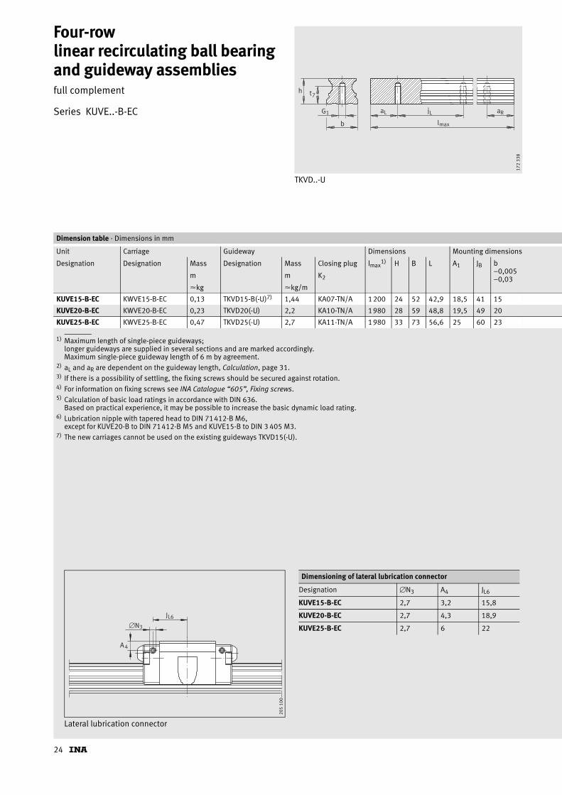
Four-row linear recirculating ball bearing and guideway assembliesfull complement
Series KUVE..-B-EC
TKVD..-U
h t
G
b
7
1 a j
l
L L
max
aR
172
338
1) Maximum length of single-piece guideways; longer guideways are supplied in several sections and are marked accordingly. Maximum single-piece guideway length of 6 m by agreement.
2) aL and aR are dependent on the guideway length, Calculation, page 31.3) If there is a possibility of settling, the fixing screws should be secured against rotation.4) For information on fixing screws see INA Catalogue “605”, Fixing screws.5) Calculation of basic load ratings in accordance with DIN 636.
Based on practical experience, it may be possible to increase the basic dynamic load rating.6) Lubrication nipple with tapered head to DIN 71412-B M6,
except for KUVE20-B to DIN 71412-B M5 and KUVE15-B to DIN 3 405 M3.7) The new carriages cannot be used on the existing guideways TKVD15(-U).
Dimension table · Dimensions in mm
Unit Carriage Guideway Dimensions Mounting dimensions
Designation Designation Mass Designation Mass Closing plug lmax1) H B L A1 JB b
–0,005–0,03m m K2
�kg �kg/m
KUVE15-B-EC KWVE15-B-EC 0,13 TKVD15-B(-U)7) 1,44 KA07-TN/A 1200 24 52 42,9 18,5 41 15
KUVE20-B-EC KWVE20-B-EC 0,23 TKVD20(-U) 2,2 KA10-TN/A 1980 28 59 48,8 19,5 49 20
KUVE25-B-EC KWVE25-B-EC 0,47 TKVD25(-U) 2,7 KA11-TN/A 1980 33 73 56,6 25 60 23
Lateral lubrication connector
A4
JL6
�N3
205
100
Dimensioning of lateral lubrication connector
Designation �N3 A4 JL6
KUVE15-B-EC 2,7 3,2 15,8
KUVE20-B-EC 2,7 4,3 18,9
KUVE25-B-EC 2,7 6 22
25
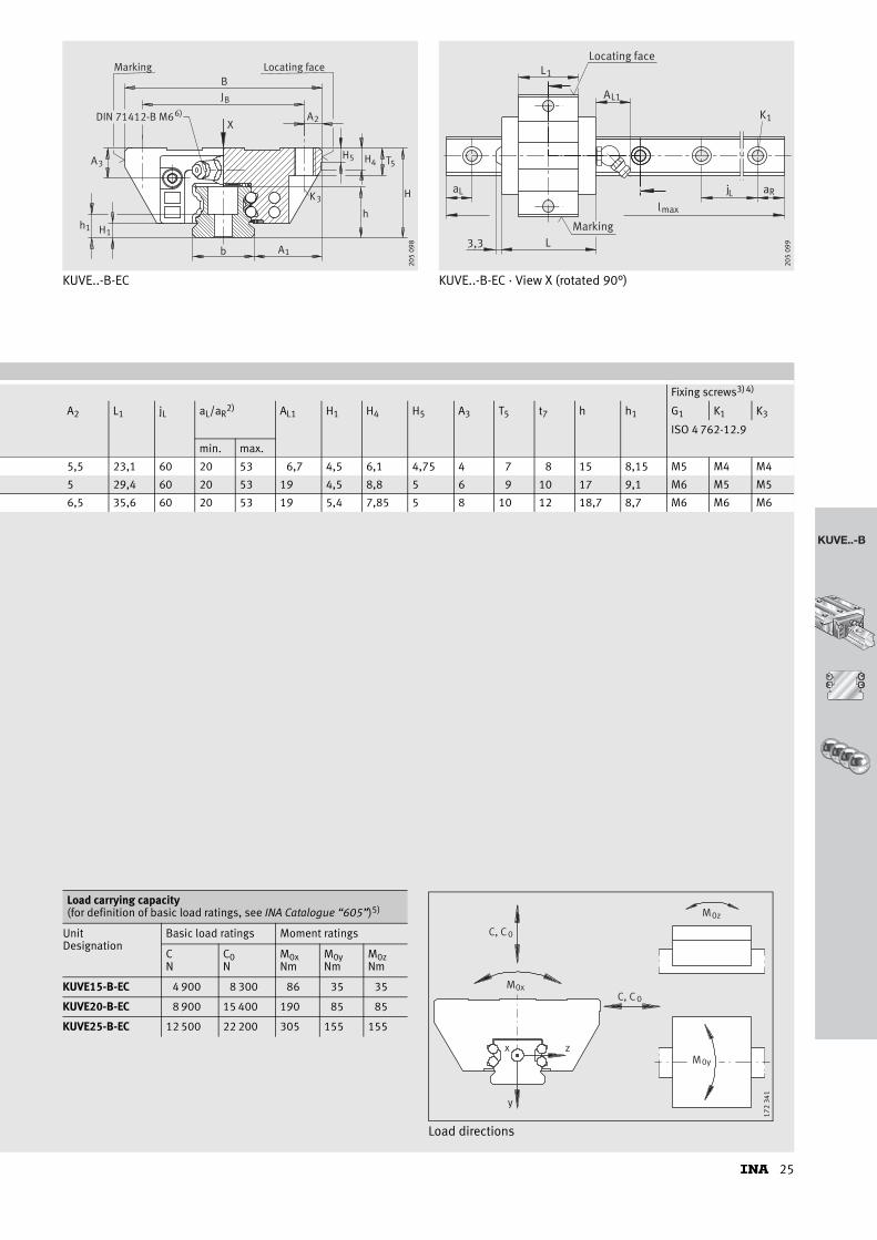
KUVE..-B
KUVE..-B-EC KUVE..-B-EC · View X (rotated 90°)
DIN 71412-B M6
Hh
A3
1 1
JB
A
B
X
H
H
TH
h
4 55
Ab 1
6)2
Marking Locating face
K3
205
098
jL aR
lmax
aL
L3,3
L1
AL1
K1
Marking
Locating face
205
099
Fixing screws3)4)
A2 L1 jL aL/aR2) AL1 H1 H4 H5 A3 T5 t7 h h1 G1 K1 K3
ISO 4 762-12.9
min. max.
5,5 23,1 60 20 53 6,7 4,5 6,1 4,75 4 7 8 15 8,15 M5 M4 M4
5 29,4 60 20 53 19 4,5 8,8 5 6 9 10 17 9,1 M6 M5 M5
6,5 35,6 60 20 53 19 5,4 7,85 5 8 10 12 18,7 8,7 M6 M6 M6
Load directions
Load carrying capacity (for definition of basic load ratings, see INA Catalogue “605”)5)
UnitDesignation
Basic load ratings Moment ratings
CN
C0N
M0xNm
M0yNm
M0zNm
KUVE15-B-EC 4 900 8 300 86 35 35
KUVE20-B-EC 8 900 15 400 190 85 85
KUVE25-B-EC 12 500 22 200 305 155 155
M
M
x
y
z
0x
M0y
0z
C, C 0
C, C 0
172
341

26
Four-row linear recirculating ball bearing and guideway assembliesfull complement
Series KUVE..-B-ESC
TKVD..-U
h t
G
b
7
1 a j
l
L L
max
aR
172
338
1) Maximum length of single-piece guideways; longer guideways are supplied in several sections and are marked accordingly. Maximum single-piece guideway length of 6 m by agreement.
2) aL and aR are dependent on the guideway length, Calculation, page 31.3) If there is a possibility of settling, the fixing screws should be secured against rotation.4) For information on fixing screws see INA Catalogue “605”, Fixing screws.5) Calculation of basic load ratings in accordance with DIN 636.
Based on practical experience, it may be possible to increase the basic dynamic load rating.6) Lubrication nipple with tapered head to DIN 71412-B M6,
except for KUVE20-B to DIN 71412-B M5 and KUVE15-B to DIN 3 405 M3.7) The new carriages cannot be used on the existing guideways TKVD15(-U).
Dimension table · Dimensions in mm
Unit Carriage Guideway Dimensions Mounting dimensions
Designation Designation Mass Designation Mass Closing plug lmax1) H B L A1 JB b
–0,005–0,03m m K2
�kg �kg/m
KUVE15-B-ESC KWVE15-B-ESC 0,17 TKVD15-B(-U)7) 1,44 KA07-TN/A 1200 24 34 42,9 9,5 26 15
KUVE20-B-ESC KWVE20-B-ESC 0,28 TKVD20(-U) 2,2 KA10-TN/A 1980 28 42 48,8 11 32 20
KUVE25-B-ESC KWVE25-B-ESC 0,35 TKVD25(-U) 2,7 KA11-TN/A 1980 33 48 56,6 12,5 35 23
Lateral lubrication connector
A4
JL6�N3
205
103
Dimensioning of lateral lubrication connector
Designation �N3 A4 JL6
KUVE15-B-ESC 2,7 3,2 15,8
KUVE20-B-ESC 2,7 4,3 18,9
KUVE25-B-ESC 2,7 6 22

27
KUVE..-B
KUVE..-B-ESC KUVE..-B-ESC · View X (rotated 90°)
H
TH
h
55
J
B
B
Hh
A3
1 1
Ab 1
ADIN 71412-B M6 26)
X G2
Locating faceMarking
205
101
jL aR
lmax
aL
L3,3
L 1 A L1
K1
Marking
Locating face
205
102
Fixing screws3)4)
A2 L1 jL aL/aR2) AL1 H1 H5 A3 T5 t7 h h1 G1 G2 K1
ISO 4 762-12.9
min. max.
5,5 23,1 60 20 53 6,7 4,5 4,75 4 7,5 8 15 8,15 M5 M4 M4
5 29,4 60 20 53 19 4,5 5 6 7,5 10 17 9,1 M6 M5 M5
6,5 35,6 60 20 53 19 5,4 5 8 10 12 18,7 8,7 M6 M6 M6
Load directions
Load carrying capacity (for definition of basic load ratings, see INA Catalogue “605”)5)
UnitDesignation
Basic load ratings Moment ratings
CN
C0N
M0xNm
M0yNm
M0zNm
KUVE15-B-ESC 4 900 8 300 86 35 35
KUVE20-B-ESC 8 900 15 400 190 85 85
KUVE25-B-ESC 12 500 22 200 305 155 155
M
M
x
y
zM0y
0z
C, C0
C, C00x
173
792
28
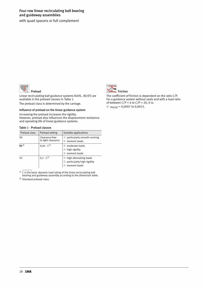
Four-row linear recirculating ball bearing and guideway assemblieswith quad spacers or full complement
PreloadLinear recirculating ball guidance systems KUVE..-B(-KT) are available in the preload classes in Table 1.
The preload class is determined by the carriage.
Influence of preload on the linear guidance systemIncreasing the preload increases the rigidity. However, preload also influences the displacement resistance and operating life of linear guidance systems.
1) C is the basic dynamic load rating of the linear recirculating ball bearing and guideway assembly according to the dimension table.
2) Standard preload class.
FrictionThe coefficient of friction is dependent on the ratio C/P. For a guidance system without seals and with a load ratio of between C/P = 4 to C/P = 20, it is:■ �KUVE = 0,0007 to 0,0015.
Table 1 · Preload classes
Preload class Preload setting Suitable applications
V0 Clearance-free to light clearance
■ particularly smooth-running■ moment loads
V12) 0,04 · C1) ■ moderate loads■ high rigidity■ moment loads
V2 0,1 · C1) ■ high alternating loads■ particularly high rigidity■ moment loads
29
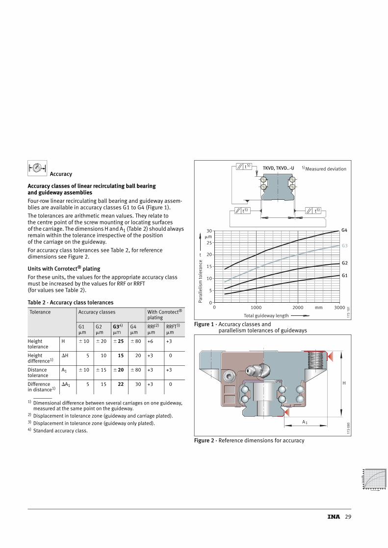
Accuracy
Accuracy classes of linear recirculating ball bearing and guideway assembliesFour-row linear recirculating ball bearing and guideway assem-blies are available in accuracy classes G1 to G4 (Figure 1).
The tolerances are arithmetic mean values. They relate to the centre point of the screw mounting or locating surfaces of the carriage. The dimensions H and A1 (Table 2) should always remain within the tolerance irrespective of the position of the carriage on the guideway.
For accuracy class tolerances see Table 2, for reference dimensions see Figure 2.
Units with Corrotect® platingFor these units, the values for the appropriate accuracy class must be increased by the values for RRF or RRFT (for values see Table 2).
1) Dimensional difference between several carriages on one guideway, measured at the same point on the guideway.
2) Displacement in tolerance zone (guideway and carriage plated).3) Displacement in tolerance zone (guideway only plated).4) Standard accuracy class.
Figure 1 · Accuracy classes and parallelism tolerances of guideways
Figure 2 · Reference dimensions for accuracy
Table 2 · Accuracy class tolerances
Tolerance Accuracy classes With Corrotect® plating
G1�m
G2�m
G34)
�mG4�m
RRF2)
�mRRFT3)
�m
Height tolerance
H � 10 � 20 � 25 � 80 +6 +3
Height difference1)
�H 5 10 15 20 +3 0
Distance tolerance
A1 � 10 � 15 � 20 � 80 +3 +3
Difference in distance1)
�A1 5 15 22 30 +3 0
t
00
1000 mm 3000
G1
G2
G3
G4
2000
5)t
5)t 5)t
5)
5
10
15
20
25�m30
Para
llelis
m to
lera
nce
Total guideway length
Measured deviationTKVD, TKVD..-U
173
181
H
A1
173
686
30
Four-row linear recirculating ball bearing and guideway assemblieswith quad spacers or full complement
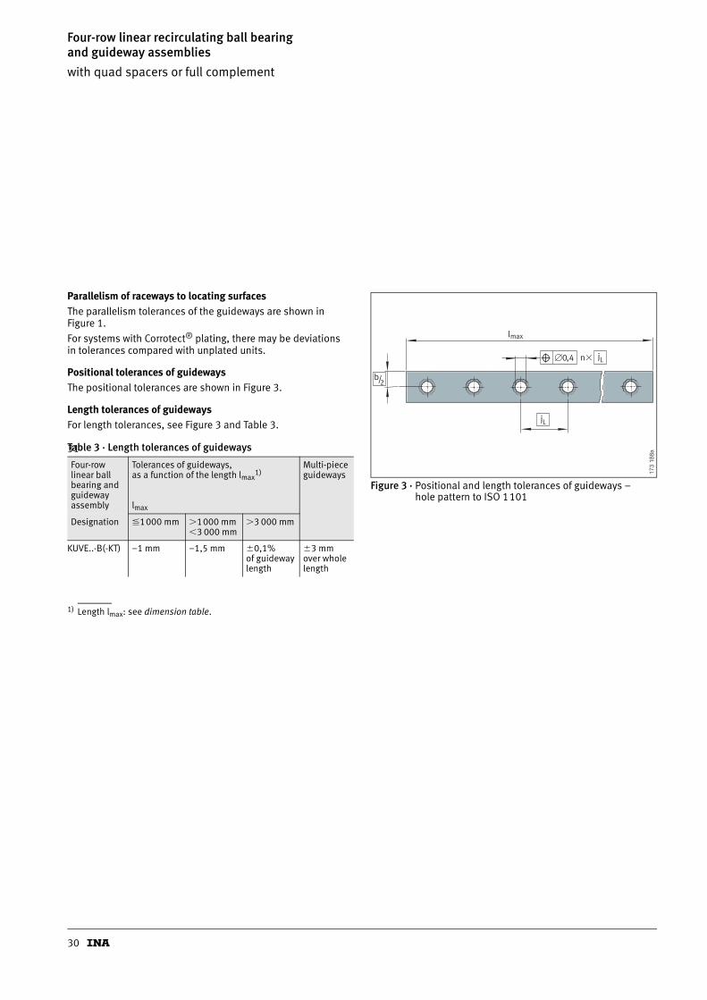
Parallelism of raceways to locating surfacesThe parallelism tolerances of the guideways are shown in Figure 1.
For systems with Corrotect® plating, there may be deviations in tolerances compared with unplated units.
Positional tolerances of guidewaysThe positional tolerances are shown in Figure 3.
Length tolerances of guidewaysFor length tolerances, see Figure 3 and Table 3.
31
1) Length lmax: see dimension table.
Figure 3 · Positional and length tolerances of guideways – hole pattern to ISO 1101
Table 3 · Length tolerances of guideways
Four-row linear ball bearing and guideway assembly
Tolerances of guideways, as a function of the length lmax
1)
lmax
Multi-piece guideways
Designation �1000 mm �1000 mm3 000 mm
�3 000 mm
KUVE..-B(-KT) –1 mm –1,5 mm �0,1%of guideway length
�3 mm over whole length
b/2
jL
jL
�0,4
l
n�
max
173
188a
31
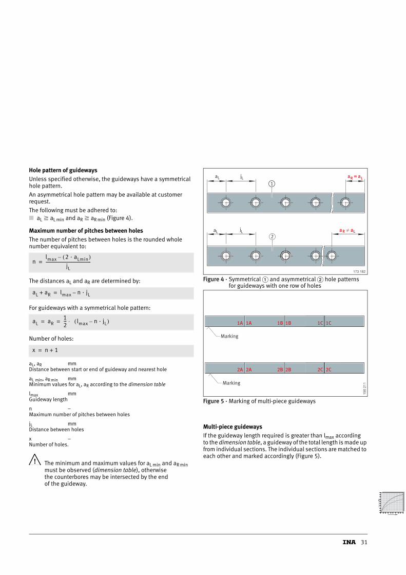
Hole pattern of guidewaysUnless specified otherwise, the guideways have a symmetrical hole pattern.
An asymmetrical hole pattern may be available at customer request.
The following must be adhered to:■ aL aL min and aR aR min (Figure 4).
Maximum number of pitches between holesThe number of pitches between holes is the rounded whole number equivalent to:
The distances aL and aR are determined by:
For guideways with a symmetrical hole pattern:
Number of holes:
aL, aR mmDistance between start or end of guideway and nearest hole
aL min, aR min mmMinimum values for aL, aR according to the dimension table
lmax mmGuideway length
n –Maximum number of pitches between holes
jL mmDistance between holes
x –Number of holes.
The minimum and maximum values for aL min and aR min must be observed (dimension table), otherwise the counterbores may be intersected by the end of the guideway.
Figure 4 · Symmetrical � and asymmetrical � hole patternsfor guideways with one row of holes
Figure 5 · Marking of multi-piece guideways
Multi-piece guidewaysIf the guideway length required is greater than lmax according to the dimension table, a guideway of the total length is made up from individual sections. The individual sections are matched to each other and marked accordingly (Figure 5).
nlmax 2 · aLmin( )–
jL--------------------------------------------=
aL aR+ lmax n · jL–=
aL aR12--- lmax n · jL–( )⋅= =
x n 1+=
aaa R LL =jL
aL jL aaR L�
1
2
173 182
1A 1B 1C
2A 2B 2C
1A 1B 1C
2A 2B 2C
Marking
Marking
156
211
32
Four-row linear recirculating ball bearing and guideway assemblieswith quad spacers or full complement
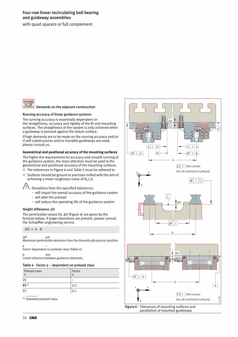
Demands on the adjacent construction
Running accuracy of linear guidance systemsThe running accuracy is essentially dependent on the straightness, accuracy and rigidity of the fit and mounting surfaces. The straightness of the system is only achieved when a guideway is pressed against the datum surface.
If high demands are to be made on the running accuracy and/or if soft substructures and/or movable guideways are used, please consult us.
Geometrical and positional accuracy of the mounting surfacesThe higher the requirements for accuracy and smooth running of the guidance system, the more attention must be paid to the geometrical and positional accuracy of the mounting surfaces.■ The tolerances in Figure 6 and Table 5 must be adhered to
■ Surfaces should be ground or precision milled with the aim of achieving a mean roughness value of Ra1,6.
Deviations from the specified tolerances:– will impair the overall accuracy of the guidance system– will alter the preload– will reduce the operating life of the guidance system.
Height difference �HThe permissible values for �H (Figure 6) are given by the formula below. If larger deviations are present, please consult the Schaeffler engineering service.
�H �mMaximum permissible deviation from the theoretically precise position
a –Factor dependent on preload class (Table 4)
b mmCentre distance between guidance elements.
1) Standard preload class.
Figure 6 · Tolerances of mounting surfaces and parallelism of mounted guideways
Table 4 · Factor a – dependent on preload class
Preload classV
Factora
V0 –
V11) 0,2
V2 0,1
ΔH a · b=
A
AA
B BA
b
A
Ab
z x
y
x z
y
t
t
t
t
t
t
t
�H
�H
C
t
b
t C
�H
Not convex
(for all machined surfaces)
Not convex
(for all machined surfaces)
173
687
33
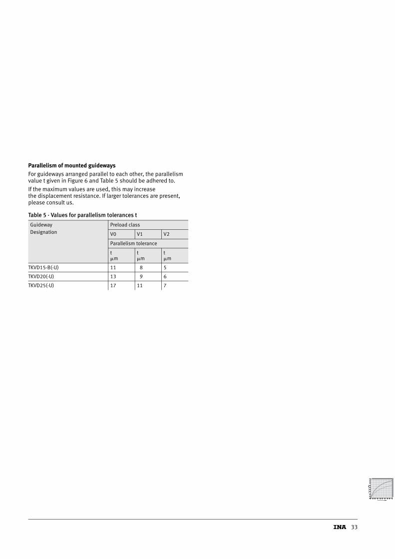
Parallelism of mounted guidewaysFor guideways arranged parallel to each other, the parallelism value t given in Figure 6 and Table 5 should be adhered to.
If the maximum values are used, this may increase the displacement resistance. If larger tolerances are present, please consult us.
Table 5 · Values for parallelism tolerances t
GuidewayDesignation
Preload class
V0 V1 V2
Parallelism tolerance
t�m
t�m
t�m
TKVD15-B(-U) 11 8 5
TKVD20(-U) 13 9 6
TKVD25(-U) 17 11 7

34
Four-row linear recirculating ball bearing and guideway assemblieswith quad spacers or full complement
Locating heights and corner radiiLocating heights and corner radii should be in accordance with Figure 7 and Table 6.
Figure 7 · Locating heights and corner radii
Table 6 · Locating heights and corner radii
Linear recirculating ball bearing and guideway assemblyDesignation
h1 h2max.
r1max.
r2max.
KUVE15-B (-H, -S, -EC, -ESC)
4,5 3,5 1 0,5
KUVE15-B-KT(-L, -H, -HL, -S, -SL)
4,5 3,5 1 0,5
KUVE20-B (-L, -S, -SL, -SN, -SNL, -N, -NL, -EC, -ESC)
5 4 1 0,5
KUVE20-B-KT(-L, -S, -SL)
5 4 1 0,5
KUVE 25-B (-L, -H, -HL, -S, -SL, -SN, -SNL, -N, -NL, -EC, -ESC)
5 4,5 1 0,8
KUVE25-B-KT(-L, -H, -HL, -S, -SL)
5 4,5 1 0,8
r
h
r
1
1
22
h
173
694

Schaeffler KG
Linear Technology Division
66424 Homburg/Saar (Germany)
Internet www.ina.com
E-Mail [email protected]
In Germany:
Phone 0180 5003872
Fax 0180 5003873
From Other Countries:
Phone +49 6841 701-0
Fax +49 6841 701-625
Every care has been taken to ensure the
correctness of the information contained
in this publication but no liability can be
accepted for any errors or omissions.
We reserve the right to make changes in
the interest of technical progress.
© Schaeffler KG · 2006, February
This publication or parts thereof may not
be reproduced without our permission.
MAI 91MA
TMR
0174
1136
0-00
00/M
AI9
1 G
B-D
0206
2.5
· Pr
inte
d in
Ger
man
y