four strand barbed wire specifications - british columbia strand barbed... · four strand barbed...
TRANSCRIPT

MFLNRO Fence Specifications – Updated July 2016 Page 1 of 18
FOUR STRAND BARBED WIRE FENCE SPECIFICATIONS
No set of fence specifications will cover all situations. The intent is to construct a good, serviceable fence. Practices and use of materials outlined below are expected to be followed and any deviation from these specifications must be discussed with and approved by a Ministry representative.
Materials and or fence components may be sampled and items failing to meet specifications will be required to be removed and replaced at the contractor’s expense.
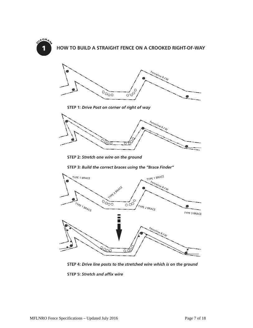
Posts: Fencelines shall be constructed in a straight line between braces. A straight line can be
achieved by driving line posts along a pre-tensioned line (Diagram 1). Posts must be set perpendicular to ground (right angles to the fence wires).
Line posts, 2.1 m x 10-12 cm (7 foot x 4-5 inches), will be "planted" a maximum of 5.5 m
(18 feet) apart. They must be No. 1 grade pressure treated fir, pine or cedar and not less than 10 cm (4 inches) in diameter or as otherwise specified by the Ministry representative. All posts must meet MOTI treated post guidelines (Section 909 - Treated Post Guidelines, Appendix 2 for more detail).
Line posts are to be dug in or driven a minimum of 81 cm (32 inches) deep. Tops must not
be cut off of fence posts unless specifically allowed in writing by Ministry representative. Cut tops must be treated with a copper sulfate mix. In boggy areas posts will be 2.4 m x 12-15 cm (8 feet x 5-6 inches) “planted” 1.22 m (48 inches) or if 2.1 m x 10-12 cm (7 foot x 4-5 inches) posts are used they will be planted 102 cm (40 inches) and spaced no more than 4.27 m (14 feet) apart. In extremely wet areas, every second seven foot post will be deadmanned.
Care should be taken to plant a post at each knoll top or draw bottom to ensure that the
bottom wire stays between 38 cm to 46 cm (15-18 inches) above ground. Dip posts must be "deadmanned" (Diagram 10). Deadmans should not extend into the right-of-way so not to interfere with livestock or wildlife. Post spacing and location may need to be adjusted or the right-of-way may need to be levelled out if bottom wire exceeds 46 cm (18 inches).
Anchor, gate, corner panels, type I and type II brace assemblies are to be installed using
2.4 m x 12-15 cm (8 feet x 5-6 inches) posts driven 1.1 m (44 inches) deep.

MFLNRO Fence Specifications – Updated July 2016 Page 2 of 18
Jack posts and A-frame posts may be constructed where it is impossible to set a post.
Treated posts or rails must be used for construction of the jack posts (Diagram 12). Sufficient weight (ie. rocks) +/- 300 lbs (136 kg) must be added to the jack post platform to ensure stability. Cut ends exposed while constructing Jack posts and A-frames must be treated with a copper sulfate mix.
Heavy metal fence posts may be used only in locations pre-approved by the Ministry
representative. Where it has been determined that treated posts cannot be “planted”, a 6 foot, heavy metal post weighing 1.25 pounds per foot may be used. Where metal posts are being used for other reasons than ground conditions and the inability to drive in a wooden post, a 7 foot heavy metal post weighing 1.25 pounds per foot must be used. Metal posts must be planted no more than 4.3 m (14 feet) apart and wired with a minimum of 12 ½ guage galvanized wire. Metal posts must not be used for brace assemblies.
Braces: The type of brace required is dependent on the change in direction shown on Diagram 2.
Angles will be checked by Ministry representative to ensure the proper brace type is constructed.
Type I brace assemblies are best suited to 90 degree corners. Hand tighten slack wire between brace posts on a type II, four post brace assembly
(Diagram 4). Alternative to the type II four post brace if approved by Ministry representative, is a three
post brace with a “hip” (Diagram 4). “Hip” brace rail can be a 2.1 m x 10-12 cm (7 foot x 4-5 inch) rail. The Ministry representative may require the installation of two additional rails or barbed wire on the “hip” brace below the top rail to prevent structural damage to the brace by livestock.
The horizontal brace rail must be centered at 99 cm (39 inches) above the ground (between
the top and third wire) and be a pressure treated 3.05 m optimum or minimum 2.95 m x 10-12 cm (10 feet or minimum 9 feet 8 inches x 4-5 inch) diameter (minimum) rail for adjustment between posts.
The horizontal brace rail must be secured with a minimum 20 cm (8 inch) Ardox spike
(Figure 8) and it is recommened that a pilot hole is drilled to guide the spike through the post and into the rail and the spike should be driven flush.
No notching for the horizontal brace rail is allowed. Counter (diagonal) bracing shall be constructed with high tensile smooth wire, doubled and
twisted. A gripple brace kit can be used for counter bracing as directed by the Ministry representative. The counter brace should be located 5 cm (2 inches) above the ground to

MFLNRO Fence Specifications – Updated July 2016 Page 3 of 18
prevent corrosion of the wire. All twitch sticks used for the counter bracing are to be pressure treated wood with a minimum 7.5 cm (3 inch) diameter x 60 – 90 cm (2 - 3 feet) in length. The twitch sticks must be resting and nailed or wired against the horizontal brace rail, on the opposite side of the barbed wire (Diagrams 3-7).
In-line brace (anchor) panels and gate brace panels may be built as a single panel. They
must follow the same specifications outlined above (Diagrams 6-7). Diagram 7 is a more cost effective in-line brace. Anchor braces should be considered at knoll tops or draw bottoms where there is a significant change in slope.
In-line brace (anchor) panels to be installed a maximum of every 200 m (1/8 mile) or as
directed by the Ministry representative using 2.4 m x 12-15 cm (8 feet x 5-6 inches) posts which are to be driven in 1.1 m (44 inches) (Diagrams 6 & 7). Proper wire tension is more difficult to achieve as the distance becomes greater between braces.
All type III braces for direction changes of less than 20 degrees are not to be tied off. This
is the only brace structure that can use 2.1 m x 10-12 cm (7 foot x 4-5 inch) posts. This brace assembly should be placed on the low pressure side of the fence where possible and safe access for a quad or horse and rider must be maintained. Additional rails or barbed wire may be required on the “hip” to prevent damage to brace rail as directed by Ministry representative. If the fence is being constructed on a highway, the “hip” must be constructed on the grazed side of the right of way. A type III brace is strongest when constructed on the outside (preferred) angle of the fence. Ensure that counter bracing is done correctly.
Jack posts can only be used for brace structures where it is impossible to set a post and
must be approved by the Ministry representative and be held down with sufficient weight (+/- 300 lbs) to ensure stability.
Wire: Barbed wire must be 12 ½ gauge twisted double strand with a minimum breaking strength
of 900 lbs. As directed by the Ministry representative it can be Canada Standard (made in Canada) or class one or three zinc coated (galvanized) wire. Class three wire must be used on barbed wire fences adjacent to highways or other roads where salt is likely to corrode the wire.
All barbed wire is to be pre-tensioned to 600 lbs and then released and stapled at 250-300
lbs per strand. All of the stretch must be taken out of the wire to prevent future loosening and sag.
Barbless 12 ½ gauge twisted double strand wire (Canada Standard or Class 1 or 3) may be
required in areas with wildlife concerns and top and bottom wire heights set at 42 and 18 inches respectively. High tensile wire should not be used other than for counter bracing unless approved by a Ministry representative.

MFLNRO Fence Specifications – Updated July 2016 Page 4 of 18
Wire is to be tied off at all brace panels, except type III. Barbed wire must be wrapped twice around the tie off post and stapled (Diagrams 3, 4, 6 and 7). Barbless wire must be wrapped three times around the tie off post and stapled.
Four strands of wire to be fastened to posts at heights of (Diagrams 3 - 8):
Number 4, top wire: 107 cm (42 inches) Number 3 wire: 79 cm (31 inches) Number 2 wire: 61 cm (24 inches) Number 1, bottom wire: 38 to 46 cm (15-18 inches)
Staples: Minimum 5 cm (two inch) barbed staples (maximum 10.5 gauge) are to be used exclusively
for securing wire to posts. Staples should never be driven home. Always rotate the staple away from the slash cut side of the staple and when stapling rise or dip posts follow the procedure in Diagram 9.
Fencing staplers are acceptable when approved by Ministry representative. When using a
fencing stapler wire must be fastened to line and brace posts with 5 cm (2 inch) barbed staples (9 guage). Power stapling of droppers to fence and gates use 3.3 cm (1 ¼ inch) 10.5 guage staples. If minor splitting occurs or dropper does not receive staple to required depth use tie wire to fasten droppers to wire. If major splitting occurs the dropper should be discarded and replaced with a new one.
Stays/Droppers: Treated wooden or cedar stays/droppers shall be installed 2 per panel, equally spaced and
must be 36 – 48 inches in length and 1 inch x 1. 5 inches wide. Some situations may may require 3 stays/droppers per panel and will be directed by Ministry representative. Wooden stays/droppers must be wired with No. 14-16 gauge wire or with loop ties of an appropriate length to all four (4) wires or attached using a power stapler as described above.
Wooden stays/droppers are to be attached on the opposite side of the stapled wire (put stay
on same side of wire as posts). Wooden stays/droppers are not to be interwoven in barbed wire and must not touch the ground (Diagram 11). It is acceptable for stays/droppers to touch the ground in cases where they function to hold the weight of the fence (eg. heavy snow pack & gates) or as directed by the Ministry representative. Wooden stays/droppers must be structurally sound as determined by a Ministry representative.
Gates: Gates are to be installed at any stock trail or roads blocked by the fence and/or at strategic
locations designated by the Ministry representative. All barbed wire gates must be constructed with pre-tensioned wire. Mechanical gate closers (ie. Ty-ten) are to be used on all gates (Diagram 8). Chain and pry bar gate closers acceptable where approved by Ministry representative.

MFLNRO Fence Specifications – Updated July 2016 Page 5 of 18
All gates must have a minimum clearance of 41 cm (16 inches) between the ground and the
bottom rail/wire and have a 5.5 m (18 foot) opening or width approved by Ministry representative. Barbed wire gates must be constructed with minimum 7.5 cm (3 inch) treated end posts and a minimum of 5 wooden stays evenly spaced (Diagram 8).
Gates need to be visible, especially where moving livestock is important and should have a false panel of rails on either side. A brace must be installed adjacent to each false panel to stretch the next section of wire from.
A hinged gate to be installed as designated by the Ministry representative. Other: High visibility may be required in riparian areas and known game crossings. The Ministry
representative will determine the type of high visibility fencing material to be used. See Appendix 1, General Requirements and Best Management Practices for Fence Construction.
Other general requirements and best management practices for fence construction can be
found in Appendix 1, General Requirements and Best Management Practices for Fence Construction.

MFLNRO Fence Specifications – Updated July 2016 Page 6 of 18
List of Materials: Posts: All wooden posts and rails must be in accordance with CSA Standard O80.
Line posts 4-5” x 7’ pointed Brace posts 5-6” x 8’ pointed Brace rails: Type I & II Type III
4-5” x 10’ 4-5” x 7’
Twitch sticks minimum 3” x 2-3’ Metal posts 6’ (heavy duty, 1.25 lbs/foot)
7’ (heavy duty, 1.25 lbs/foot) Rock Jack posts 4-5” diameter post or rail cut to length Jack post (A-frame) 4-5” diameter post or rail cut to length
Wire:
Barbed wire Canada Standard (made in Canada) or Class I or III galvanized (as directed by Ministry representative)
Brace wire High tensile smooth wire, doubled and twisted
Dropper ties No. 14-16 gauge wire or loop ties Power fastening accepted upon approval
Other Hardware:
Staples: • for attaching barbed wire to posts • for attaching droppers to barbed wire
(if using power stapler for attaching droppers)
2” barbed (maximum 10.5 gauge) 1 ¼” 10.5 gauge
Brace spike 1 cm (3/8 inch) diameter x miniumum 20 cm (8 inch) Ardox spike
MFLNRO Fence Specifications – Updated July 2016 Page 7 of 18

MFLNRO Fence Specifications – Updated July 2016 Page 8 of 18
FOR X = 10 FEET Y ANGLE
1 FT. 9 IN. 10° 3 FT. 8 IN. 20° 5 FT. 9 IN. 30° 8 FT. 5 IN. 40° 11 FT. 11 IN. 50° 17 FT. 4 IN. 60°
60° + Brace Type I & Type II
20° - 60° Brace Type II
0° - 20° Brace Type III
0° - 20° Brace Type III 20° - 60° Brace Type II 60° + Brace Type I & Type II

MFLNRO Fence Specifications – Updated July 2016 Page 9 of 18
TYPE I BRACE ASSEMBLY (60° +)
Wire Spacing for Four Stand
Barbed Wire
Number 4 Top Wire at 42” Number 3 Wire at 31” Number 2 Wire at 24”
Number 1 Bottom Wire at 15”-18”
42” 31” 24” 15-18”
Detail: Min 8” Ardox spike
(Most suitable for 90 degree corners.)

MFLNRO Fence Specifications – Updated July 2016 Page 10 of 18
5-6” 8’ Brace Posts
42” 31” 24” 15-18”
4-5” 7’ Fence Posts
TYPE II BRACE ASSEMBLY 20°- 60°
If a fence change of direction occurs when it is appropriate to tie off the fence wires, a separate end brace can be constructed for each fence section. Rather than ‘share’ a common tie off post, each section is tied off to a separate end post producing no forces out of line with the braces. This requires an extra driven post per corner and ‘slack’ wiring the opening often used in changing fence direction over 20°.
4 Post Brace
Alternative Type II if approved by Ministry representative for changes of direction of 20 to 60 degrees: 3 post brace with a hip. 5-6” x 8 foot posts used for construction. 4-5” x 10 rails required along fenceline, 4-5” x 7 foot post and rail acceptable on hip brace.

MFLNRO Fence Specifications – Updated July 2016 Page 11 of 18
TYPE III BRACE ASSEMBLY (0°-20°)
4-5” 7’ Fence Posts
4-5” 7’ Fence Posts
42” 31” 24” 15-18”
For all braces, use high tensile wire. Wrap twice around posts; tighten; insert twitch stick and twist.
Detail: Min 8” Ardox brace spike
Known as: “hip catcher” or “bisector” brace
Example of additional rails added to Type III brace.

MFLNRO Fence Specifications – Updated July 2016 Page 12 of 18
NOTE: This brace is to be used every 200m (1/8 mile) if the fence is running in a straight line. The longer the distance between tie-off points, the more difficult it is to achieve proper wire tension. Consider shorter distances between tie-off points to get all of the stretch out of the wire and achieve proper wire tension.
42”
31”
24”
15-18”
Optimum 10’ 4-5” treated rail
8’ 5-6” brace posts
Double wrap around the posts, 1” between opposite wires
Brace – High tensile wire. Wrap twice around posts; tighten; insert twitch stick at centre and twist. Twitch stick rests on opposite side of the barbed wire and nailed or wired to brace rail.
Detail: Min 8” Ardox brace spike

MFLNRO Fence Specifications – Updated July 2016 Page 13 of 18
NOTE: This brace is to be used every 200m (1/8 mile) if the fence is running in a straight
line.
5-6” 8’ Brace Posts
Wire Spacing for Four Strand Barbed Wire
Number 4 Top Wire at 42” Number 3 Wire at 31” Number 2 Wire at 24”
Number 1 Bottom Wire at 15-18”
42”
31”
24”
15-18”
Optimum 10’ 4-5” treated rail
Brace – High tensile wire, wrapped twice around posts; tighten; insert twitch stick at centre and twist. Twitch stick rests on opposite side of the barbed wire and nailed or wired to brace rail.
Detail: Min 8” Ardox spike

MFLNRO Fence Specifications – Updated July 2016 Page 14 of 18
8’ x 5-
Anchor Brace Assembly for Gates and Cattleguards
Tie off fence here
Optimum 10’ 4-5” treated rail
Optimum 10’ 4-5” treated rail
Optimum 10’ 4-5” treated rail
Mechanical gate closer
Clearance 16” Minimum (not to scale), recommended 18’ width
Detail: Min 8” Ardox brace spike
Detail: Min 8” Ardox brace spike
Rail “sacrifice” panel tied to cattleguard so that integrity of fence is not compromised should it be hit by a vehicle or grader.
8’ x 5-6” posts
18’ gate with 5 droppers
False panel for visibility
8’ x 5-6” posts 3” treated posts
False panel for visibility
Mechanical gate closer Tie off fence here
Gate and catttlebuard diagrams not to scale

MFLNRO Fence Specifications – Updated July 2016 Page 15 of 18
9

MFLNRO Fence Specifications – Updated July 2016 Page 16 of 18
See insert
Steep Dip - 1 or 2 steel posts (dependent on angle and soil conditions) or one 7’ treated post can be used. Steel or treated post should be nailed and/or wired and stapled to upright post.

MFLNRO Fence Specifications – Updated July 2016 Page 17 of 18
Wooden Stays are to be wired to each barbed wire strand (ie. In a four strand barbed wire fence, wooden stays are wired on four locations). Stays can be power stapled if
approved by Ministry representative.
#14 – 16 guage wire or loop ties

MFLNRO Fence Specifications – Updated July 2016 Page 18 of 18
Appendicies: Appendix 1 – General requirements and best management practices for fence construction Appendix 2 – Treated Post Guidelines
2” staple
A-Frame
A second horizontal post on the ground on the opposite side of the vertical and diagonal post creates a cradle for rocks to provide additional support to an A-frame post (not shown in diagram).