fp2000 series digital paddlewheel flowmeter · digital paddlewheel flowmeter. rate - t otalizer rt...
TRANSCRIPT

FP2000 SERIESDIGITAL PADDLEWHEELFLOWMETER

RTRate - Totalizer
RESET
MODE
GALLONS PER MINUTE
1.0 INTRODUCTION
Congratulations on purchasing the electronic flow meter. It is designed to measure the flow of a fluid in a pipe. The meter is factory calibrated to any engineering units and displays the rate of flow or the total of flow on a 6 digit LCD display. Two AAA batteries power the unit for up to one year. There are three models are available:
R is a rate meter - designed to measure and display the rate of flow.
T is a totalizer meter - designed to measure and display the total flow.
RT is a rate/totalizer meter - designed to measure and display both the rate of flow and the total flow.
Page 2
TABLE OF CONTENTS
SECTION HEADING PAGE
1 Introduction 2
2 Specifications 3
3 Features 3
4 How to install 4
4.1 Mounting location 4
4.2 Pipe Flow Stream Requirements 4
4.3 Installing the Molded In-Line Fittings 6
5 How to Operate 7
6 Flow Ranges 8
7 How to Maintain 9
8 Troubleshooting 8
9 Replacement Parts List 10-11
3.03 in.(77 mm)
2.00 in.(50.8 mm)
Fig. 1
3.10 in.(78.7 mm) Union Nut
4.93 in.(125.2 mm)

Note: All diagrams are strictly for guideline purposes only. Always consult an expert before installing theit on specialized systems.
4.0 HOW TO INSTALL THE PADDLEWHEEL FLOWMETER
4.1 MOUNTING LOCATION
Type Of Disturbance Minimum Inlet Pipe Minimum Outlet Length Pipe Length
Flange 10 X Pipe I.D. 5 X Pipe I.D
Reducer 15 X Pipe I.D. 5 X Pipe I.D.o 20 X Pipe I.D. 5 X Pipe I.D.90 Elbow
o 25 X Pipe I.D. 5 X Pipe I.D.Two 90 Elbows -1 Direction
oTwo 90 Elbows -2 40 X Pipe I.D. 5 X Pipe I.D.
Directions
Pump Or Gate Valves 50 X Pipe I.D. 5 X Pipe I.D.
! The pipe must be completely full at all times. Air bubbles or air pockets in the flow stream will adversely affect the reading. A small amount of back pressure is recommended in horizontal runs of pipe.
! It is powered by two AAA batteries. Life expectancy is one year minimum.
Although the FP2000 is designed to withstand outdoor conditions, a cool, dry location where the unit can be easily serviced is recommended. The life of the LCD display will be severely reduced when installed in direct sunlight. Do not install the meter so that the LCD is in direct sunlight.
The FP2000 can be mounted on horizontal or vertical runs of pipe (see figure 4, 5 and 6). Mounting at the twelve o'clock position on horizontal pipe is recommended. Mounting anywhere around the diameter of vertical pipe is acceptable, however, the pipe must be completely full of water at all times. Back pressure is essential on downward flows.
The FP2000 accuracy is affected by disturbances such as pumps, elbows, tees, valves in the flow stream. Install the meter in a straight run of pipe as far as possible from any disturbances. The distance required for accuracy will depend on the type of disturbance.
!
!
Note: It should be serviced by qualified persons only.
Page 4
! Accuracy is based on steady, undisturbed flow with a fully developed turbulent flow profile. Pulsating, swirling and other disruptions in the flow stream will effect the meter’s accuracy.
! Factory calibrated to ± 2% of full scale rate reading. When measuring total flow, accumulated error over time must be considered. Accuracy is based on laboratory testing of nominal pipe dimensions. Your actual accuracy will vary based on your actual pipe I.D. And other installation factors.
! There are two basic types of flow profiles; turbulent and laminar (see figure 3). Turbulent flow exists when the speed of the fluid flowing in the pipe is nearly constant across the entire width of the pipe. This is typical of low viscosity fluids; like water, flowing at high velocity. Laminar flow exists when the speed of the fluid flowing in the center of the pipe is greater than the speed of the fluid at the outer edge near the pipe wall. This is typical of high viscosity fluids flowing at low velocity. Because it is measuring the fluid near the pipe wall only (especially in larger pipe sizes), a constant flow velocity across the flow stream is required.
!
4.2 PIPE FLOW STREAM REQUIREMENTS
3. FEATURES
Easy to read .35" high, six digit LCD display.Weather resistant enclosure.
Installs quickly on existing pipe.Corrosion resistant PVDF sensor, ABS
Factory calibrated -nothing to program. enclosure.
Minimal maintenance required. High accuracy.
No pressure drop. Large calibrated flow range.
!!
!!
!
! !
! !
Page 3
2.0 SPECIFICATIONS
Maximum Working Pressure* 300 psig / 20.7 baro oMaximum Fluid Temperature* 200 F / 93.3 C -Saddle and sensor only
o o200 F / 93.3 C -When mounted on polypropylene and PVDF inline units.
o o o oAmbient Temperature Range 32 to 110 F / 0 to 43 C
Enclosure NEMA 4X (acceptable for outdoor use)
NOTE: Protect the LCD display from direct sunlight.
Accuracy +/-2% of full scale rate reading
Repeatability +/-1% of full scale rate reading
Power Requirements Two standard AAA alkaline batteries (included)
Battery Life Expectancy 1 year minimum
*Temperature vs. Pressure
PSIg (BAR)
Temperature
150°F (65.5°C)
175°F (79.4°C)
200°F (93.3°C)
125°F (51.6°C)
100°F (37.8°C)
70°F (21.1°C)0 (0) 60 (4.1) 120 (8.3) 180 (12.4) 240 (16.5) 300 (20.7)
When mounted on Polypropylene and PVDF inline units
*Pressure and temperature limits are inversely proportional.

Page 5
Pipe Cross Section
Flow Velocity Profile
Fully DevelopedTurbulent Flow
Laminar Disturbed Flow(due to swirling)
To determine which type of flow exists in your installation, the following is required:
Flow rate of the fluid in GPM -Q
Specific gravity of the fluid -G
Pipe inside diameter in inches -D
Fluid viscocity in centepoise -V
Use the following equation to determine the REYNOLDS NUMBER:
REYNOLDS NUMBER = 3160 x Q x GD x V
Flow conditions with a Reynolds Number greater than 4000 is fully developed turbulent flow. A Reynolds Number less than 2000 is laminar flow. It requires a Reynolds number greater than 4000 to maintain accuracy.
Fig. 3
MINIMUMINPUT
LENGTH
MINIMUMOUTPUTLENGTH
I.D.
FLO
W
Vertical Mount
Fig. 4
Horizontal Mount
MINIMUMINPUT
LENGTH
MINIMUMOUTPUTLENGTH
I.D.FLOW
MINIMUMINPUT
LENGTH
MINIMUMOUTPUTLENGTH
I.D.FLOW
Fig. 5
Fig. 6
RTRate - Totalizer
RESET
MODE
GALLONS PER MINUTE
RTRate - Totalizer
RESET
MODE
GALLONS PER MINUTE
Body Description
3/8” MPT-std flow
1/2” MPT-std flow
3/4” MPT-std flow
1.0” MPT-std flow
3/8” MPT-low flow
1/2” MPT-low flow
Length
L
4.73”
5.09”
5.25”
5.65”
4.73”
5.09”
3/4” MPT-low flow
1.0” MPT-low flow
5.25”
5.65”
Page 6
Height
H
5.38”
5.38”
5.57”
5.57”
5.29”
5.29”
5.38”
5.57”
Nominal Pipe Size
3/8”
1/2”
3/4”
1.0”
3/8”
1/2”
3/4”
1.0”
Fig. 10
Molded in-line body with M P T
PipeH
L
RTRate - Totalizer
RESET
MODE
GALLONS PER MINUTE
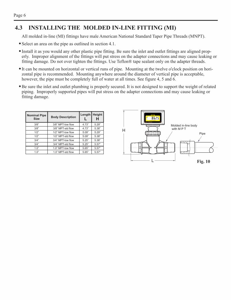
4.3 INSTALLING THE MOLDED IN-LINE FITTING (MI)
All molded in-line (MI) fittings have male American National Standard Taper Pipe Threads (MNPT).
Select an area on the pipe as outlined in section 4.1.
Install it as you would any other plastic pipe fitting. Be sure the inlet and outlet fittings are aligned prop-erly. Improper alignment of the fittings will put stress on the adapter connections and may cause leaking or fitting damage. Do not over tighten the fittings. Use Teflon® tape sealant only on the adapter threads.
It can be mounted on horizontal or vertical runs of pipe. Mounting at the twelve o'clock position on hori-zontal pipe is recommended. Mounting anywhere around the diameter of vertical pipe is acceptable, however, the pipe must be completely full of water at all times. See figure 4, 5 and 6.
Be sure the inlet and outlet plumbing is properly secured. It is not designed to support the weight of related piping. Improperly supported pipes will put stress on the adapter connections and may cause leaking or fitting damage.
!
!
!
!
Page 5
Pipe Cross Section
Flow Velocity Profile
Fully DevelopedTurbulent Flow
Laminar Disturbed Flow(due to swirling)
To determine which type of flow exists in your installation, the following is required:
Flow rate of the fluid in GPM -Q
Specific gravity of the fluid -G
Pipe inside diameter in inches -D
Fluid viscocity in centepoise -V
Use the following equation to determine the REYNOLDS NUMBER:
REYNOLDS NUMBER = 3160 x Q x GD x V
Flow conditions with a Reynolds Number greater than 4000 is fully developed turbulent flow. A Reynolds Number less than 2000 is laminar flow. It requires a Reynolds number greater than 4000 to maintain accuracy.
Fig. 3
MINIMUMINPUT
LENGTH
MINIMUMOUTPUTLENGTH
I.D.
FLO
W
Vertical Mount
Fig. 4
Horizontal Mount
MINIMUMINPUT
LENGTH
MINIMUMOUTPUTLENGTH
I.D.FLOW
MINIMUMINPUT
LENGTH
MINIMUMOUTPUTLENGTH
I.D.FLOW
Fig. 5
Fig. 6
RTRate - Totalizer
RESET
MODE
GALLONS PER MINUTE
RTRate - Totalizer
RESET
MODE
GALLONS PER MINUTE
Body Description
3/8” MPT-std flow
1/2” MPT-std flow
3/4” MPT-std flow
1.0” MPT-std flow
3/8” MPT-low flow
1/2” MPT-low flow
Length
L
4.73”
5.09”
5.25”
5.65”
4.73”
5.09”
3/4” MPT-low flow
1.0” MPT-low flow
5.25”
5.65”
Page 6
Height
H
5.38”
5.38”
5.57”
5.57”
5.29”
5.29”
5.38”
5.57”
Nominal Pipe Size
3/8”
1/2”
3/4”
1.0”
3/8”
1/2”
3/4”
1.0”
Fig. 10
Molded in-line body with M P T
PipeH
L
RTRate - Totalizer
RESET
MODE
GALLONS PER MINUTE
4.3 INSTALLING THE MOLDED IN-LINE FITTING (MI)
All molded in-line (MI) fittings have male American National Standard Taper Pipe Threads (MNPT).
Select an area on the pipe as outlined in section 4.1.
Install it as you would any other plastic pipe fitting. Be sure the inlet and outlet fittings are aligned prop-erly. Improper alignment of the fittings will put stress on the adapter connections and may cause leaking or fitting damage. Do not over tighten the fittings. Use Teflon® tape sealant only on the adapter threads.
It can be mounted on horizontal or vertical runs of pipe. Mounting at the twelve o'clock position on hori-zontal pipe is recommended. Mounting anywhere around the diameter of vertical pipe is acceptable, however, the pipe must be completely full of water at all times. See figure 4, 5 and 6.
Be sure the inlet and outlet plumbing is properly secured. It is not designed to support the weight of related piping. Improperly supported pipes will put stress on the adapter connections and may cause leaking or fitting damage.
!
!
!
!

5.0 HOW TO OPERATE
Note: The calibrated units of measure such as GPM, LPM, M3H, GALLONS, LITERS, CUBIC METERS, ect., And the decimal point location are pre-programmed at the factory to standard flow ranges (see chart). Any unit of measure can be factory programmed. Please contact the factory for details.
! The meter is shipped from the factory with 2 AAA batteries installed.
! When measuring continuous flow (i.e. 24 hours per day, 7 days per week), do not operate the meter in the upper 25% of the calibrated flow range. The paddle speed in these high flow ranges is fast. Damage to the paddle may occur if the meter is allowed to run continuously at the high flow rate, especially with corrosive or abrasive fluids.
R: The R is the basic rate meter. The meter will display the rate of flow from .01 through 999999 in any engineering units. Some standard units of measure are GPM, GPH, GPD, LPM, LPH, LPD, M3H, etc.
T: The T is the basic totalizer meter. The meter will display the total flow amounts from .01 through 999999 in any engineering units. Some standard units of measure are GALLONS, LITERS, CUBIC METERS. Pressing and holding the RESET button (located on the front panel) for at least 2.0 seconds resets the total to zero. This feature can be disabled -- see Fig. 12 below.
RT: The RT is the rate and totalizer meter. The meter will display the flow rate amounts and the total flow amounts from .01 through 999999 in any engineering units. Some standard units of measure are GALLONS PER MINUTE, GALLONS PER HOUR, GALLONS PER DAY, LITERS PER MINUTE, LITERS PER HOUR, LITERS PER DAY, CUBIC METERS PER HOUR, CUBIC METERS PER DAY. Pressing the RESET button (located on the front panel) toggles the display between flow rate and total flow. Pressing and holding the RESET button for at least 2.0 seconds while the total flow value is displayed will reset the total to zero. This feature can be disabled -- see Fig. 12 below.
!
!
!
Page 7
21
-+
Red wire(Positive lead)
Black wire(Negative lead)
Terminal blocks(AC Coil sensor input)
Jumpers(Front Panel Totalizer Reset
Enable/Disable)
Header pins(Tail membrane connector)
Battery size: two AAA (1.5 V each)
Screw size: #4 x .50 Philip oval “A”Mounting holes (x2)
Fig. 12
RTRate - Totalizer
RESETMODE
RBFlow Rate Meter
GPMGALLONS PER MINUTE
TBFlow Totalizer
RESET
GALLONS
R T RT
Circuit Board Jumper Not
Installed (open)JumperInstalled
JUMPER CONFIGURATION
Total flow resetto zero Enable
(Factory default)
Total flow resetto zero Disable
! It is factory calibrated to ± 2% of full scale rate reading. When measuring total flow, accumulated error over time must be considered. Accuracy is based on laboratory testing of nominal pipe dimensions. Your actual accuracy will vary based on your actual pipe I.D. And other installation factors.
! Due to increased wear on the paddle and axle, continuous operation at the upper 25% of the flow range is not recommended.
6.0 FLOW RANGES
Page 8
IPS PIPES
MOLDED INLINE BODIES - Standard Flow Range #1 [Min - Max]
2.00 - 20.00
6.00 - 60.00
6.00 - 60.00
Pipe Size
3/8” INLINE
1.5” INLINE
1 /2” INLINE
1.5” INLINE
2.0” INLINE
3/4” INLINE
1.5” INLINE
2.0” INLINE
1.0” INLINE
2.0” INLINE
2.0” INLINE
GPM 1
48.0 - 480.0
240 - 2400
.800 - 8.000
4.00 - 40.00
3.00 - 30.00
10.0 - 100.0
10.0 - 100.0
5.00 - 50.00
4.00 - 40.00
20.0 - 200.0
GPH 1
120 - 1200
360 - 3600
360 - 3600
300 - 3000
240 - 2400
1200 - 12000
GPD 1
1100 - 11000
5760 - 57600
2800 - 28000
8640 - 86400
8640 - 86400
4320 - 43200
14400 - 144000
14400 - 144000
7200 - 72000
5760 - 57600
28800 - 288000
180 - 1800
600 - 6000
600 - 6000
LPM 1
180 - 1800
900 - 9060
3.00 - 30.00
15.0 - 151.0
7.00 - 70.00
23.0 - 227.0
23.0 - 227.0
11.0 - 110.0
38.0 - 380.0
38.0 - 380.0
20.0 - 200.0
15.0 - 151.0
76.0 - 757.0
LPH 1
420 - 4200
1380 - 13620
1380 - 13620
660 - 6600
2280 - 22800
2280 - 22800
1200 - 12000
900 - 9060
4560 - 45420
M3H 1
0.180 - 1.800
0.900 - 9.060
0.420 - 4.200
1.380 - 13.620
1.380 - 13.620
0.660 - 6.600
2.280 - 22.800
2.280 - 22.800
1.20 - 12.00
0.900 - 9.060
4.560 - 45.420
MOLDED INLINE BODIES - Low Flow Range #2 [Min - Max]
.500 - 5.000
Pipe Size
3/8” INLINE
1 /2” INLINE
3/4” INLINE
1.0” INLINE
GPM 2
20.0 - 200.0.400 - 4.000
.800 - 8.000
2.00 - 20.00
GPH 2
30.00 - 300.0
120 - 1200
GPD 2
550 - 5500
700 - 7000
1100 - 11000
2800 - 28000
48.0 - 480.0
LPM 2
60.0 - 600.01.00 - 10.00
2.00 - 20.00
3.00 - 30.00
7.00 - 70.00
LPH 2
120 - 1200
180 - 1800
420 - 4200
M3H 2
0.060 - 0.600
0.120 - 1.200
0.180 - 1.800
0.420 - 4.200
(Meet ASTM-D-1785)

Page 9
8.0 TROUBLESHOOTINGSituation: Leaking
Cause: Improper installation .............................Solution: Page 6, section 4.3
Page 7, section 4.3.1 thru 4.3.4
Page 8, section 4.4, 4.5
Worn or damaged O-rings......................Solution: Page 12, section 7.3
Situation: Moisture inside enclosure
Cause: Condensation .........................................Solution: Page 12, section 7.4
Damaged panel gasket ...........................Solution: Page 12, section 7.5
Situation: Flow rate reading is inaccurate
Cause: Improper installation..............................Solution: Page 6, section 4.3
Improper velocity profile........................Solution: Page 4, section 4.1, 4.2
Improper alignment / installation...........Solution: Page 7, section 4.3.3
Worn paddle and/or axle.........................Solution: Page 12, section 7.1
Accumulated reading error......................Solution: Page 10, section 6.1
Situation: No display
Cause: Electronics damaged...............................Solution: Page 12, section 7.5
Dead batteries.........................................Solution: Page 12, section 7.6
Situation: Display shows zero flow
Cause: Electronics damaged...............................Solution: Page 12, section 7.6
Flow rate is out of range.........................Solution: Page 10, section 6.0
7.0 HOW TO MAINTAIN
It requires very little maintenance, however, some conditions will cause increased wear on the paddle and/or possible damage to the unit. Damage caused by corrosive or abrasive fluids is not covered under warranty.
! Periodically remove the sensor assembly from the pipe fitting and inspect the meter for signs of wear and obstruc-tions. Clean the paddle of any foreign objects. Paddle and axle wear can be caused by chemical attack and/or abrasive fluids. Replace the paddle and axle if worn. Various axle materials are available for corrosive fluids.
! Although the meter is capable of operating at the high end of the flow range, the meter should not be allowed to operate continuously at flow rates in the upper 1/4 or 25% of the calibrated flow range. The paddle and axle life is directly related to the rate of flow and the fluid being measured. Corrosive and abrasive fluids moving at high flow rates will cause increased wear requiring frequent inspection and maintenance. Ceramic, titanium or nickel axles are available for corrosive and abrasive fluids.
! O-rings should be inspected periodically. Immediately replace the o-rings at any sign of wear, swelling, cracking or discoloration.
! The meter is designed to withstand minor condensation inside the enclosure. Prolonged excessive moisture inside the enclosure, due to high humidity conditions, may damage the meter. Reduce the humidity or move the meter to a less humid location.
! Replace the two AAA batteries every 12 months. The program memory is “non-volitile” and will not erase when replacing the batteries. Processing power will be maintained for about 45 seconds, preventing the lose of totalizing data, while the batteries are being replaced. To replace the batteries, open the rear panel of the enclosure by removing the two Phillips screws. After replacing the batteries, be sure the foam insert is in place and the panel gasket seal is in good condition, before closing the rear panel.
! Test the electronics by removing the sensor assembly from the pipe fitting and spinning the paddle by hand. While spinning, the number “0” reading in the display window indicates that the battery is supplying power to the meter but a signal is not being processed by the circuitry. In this case, the circuitry must be serviced by an authorized service center.
! Although it is designed to withstand outdoor conditions, a cool, dry location where the unit can be easily serviced is recommended. The life of the LCD display will be severely reduced when installed in direct sunlight. Do not install the meter so that the LCD is in direct sunlight.
Arrow
Directi
on
Step 1: Locate notch on The sensor body.
Step 2: Push shaft out in the arrow pointing Direction.
Step 3: Replace the paddle, then press shaft back into place in the Opposite direction.
Fig. 13
Paddle Removal
Page 10
9.0 PARTS LIST
Item Part #
1 70000-783
2 90003-021
3 90007-589
4 71000-238
5 91001-051
6 90011-080
71000-386
7
90012-198
90012-199
90012-200
90012-201
90012-202
8 76001-187
10 90011-169
11 90013-215
12 90008-318
13 90006-590
14 90008-319
15 90002-203
16 90011-113
90012-221
90012-222
Description
Paddle assembly PVDF
O-ring 022 Viton E60
Axle PVDF
Sensor body assembly no paddle
Union nut
Screw #6 x .37 PH Pan B 18/8
Screw #4 x .25 Phil Pan “A”
Label R GPM
Label R GPH
Label R LPM
Label R LPH
Label R M3H3
Housing
Kit circuit board R
Foam pad 1.25 x 1.25 x 2.25
Battery each AAA
Gasket
Battery clip
Rear plate
Screw #4 x .50 Phil oval "A"
Label T overlay
Label R overlay
Qty
1
2
2
1
1
1
2
1
1
1
2
1
1
1
1
1
1
1
2
1
1
1
9 71000-387 Kit circuit board R 1
71000-388 Kit circuit board TB 1
Page 11
Pipe Fitting
RT Rate - Totalizer
RESET
MODE
GALLONS PER MINUTE
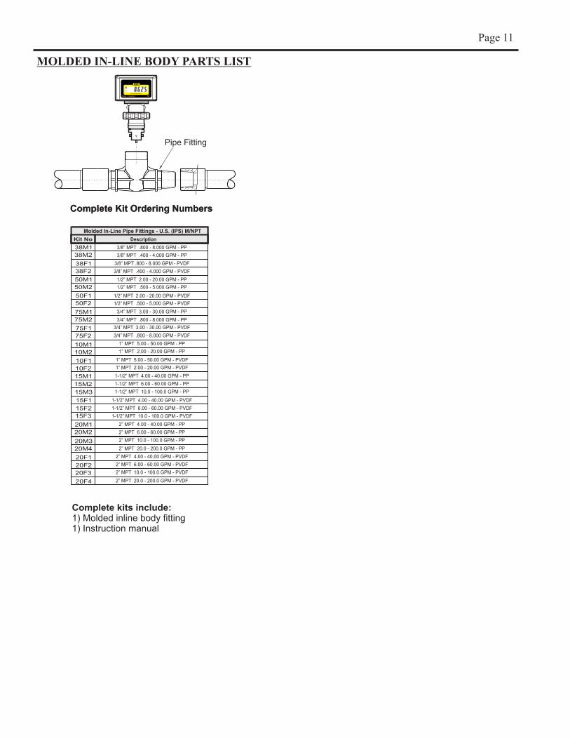
MOLDED IN-LINE BODY PARTS LIST
Complete Kit Ordering Numbers
Machined In-Line Pipe Fittings - U.S. (IPS) F/NPT
Kit No
38M1
38M2
38F1
38F2
50M1
50M2
50F1
50F2
75M1
75M2
75F1
75F2
10M1
10M2
10F1
10F2
Description
15M1
15M2
15M3
15F1
15F2
15F3
20M1
20M2
20F2
20F3
20F4
Complete Kit Ordering Numbers
Molded In-Line Pipe Fittings - U.S. (IPS) M/NPT
Kit No Description
3/8” MPT .800 - 8.000 GPM - PP
3/8” MPT .400 - 4.000 GPM - PP
3/8” MPT .800 - 8.000 GPM - PVDF
3/8” MPT .400 - 4.000 GPM - PVDF
1/2” MPT 2.00 - 20.00 GPM - PP
1/2” MPT .500 - 5.000 GPM - PP
3/4” MPT 3.00 - 30.00 GPM - PP
3/4” MPT .800 - 8.000 GPM - PP
1” MPT 5.00 - 50.00 GPM - PP
1” MPT 2.00 - 20.00 GPM - PP
1-1/2” MPT 4.00 - 40.00 GPM - PP
1/2” MPT 2.00 - 20.00 GPM - PVDF
1/2” MPT .500 - 5.000 GPM - PVDF
3/4” MPT 3.00 - 30.00 GPM - PVDF
3/4” MPT .800 - 8.000 GPM - PVDF
1” MPT 5.00 - 50.00 GPM - PVDF
1” MPT 2.00 - 20.00 GPM - PVDF
20M3
20M4
20F1
1-1/2” MPT 6.00 - 60.00 GPM - PP
1-1/2” MPT 10.0 - 100.0 GPM - PP
1-1/2” MPT 4.00 - 40.00 GPM - PVDF
1-1/2” MPT 6.00 - 60.00 GPM - PVDF
1-1/2” MPT 10.0 - 100.0 GPM - PVDF
2” MPT 4.00 - 40.00 GPM - PP
2” MPT 6.00 - 60.00 GPM - PP
2” MPT 10.0 - 100.0 GPM - PP
2” MPT 20.0 - 200.0 GPM - PP
2” MPT 4.00 - 40.00 GPM - PVDF
2” MPT 6.00 - 60.00 GPM - PVDF
2” MPT 10.0 - 100.0 GPM - PVDF
2” MPT 20.0 - 200.0 GPM - PVDF
Complete kits include:1) Molded inline body fitting1) Instruction manual
M-4631 / 0408

Page 11
Pipe Fitting
RT Rate - Totalizer
RESET
MODE
GALLONS PER MINUTE
MOLDED IN-LINE BODY PARTS LIST
Complete Kit Ordering Numbers
Machined In-Line Pipe Fittings - U.S. (IPS) F/NPT
Kit No
38M1
38M2
38F1
38F2
50M1
50M2
50F1
50F2
75M1
75M2
75F1
75F2
10M1
10M2
10F1
10F2
Description
15M1
15M2
15M3
15F1
15F2
15F3
20M1
20M2
20F2
20F3
20F4
Complete Kit Ordering Numbers
Molded In-Line Pipe Fittings - U.S. (IPS) M/NPT
Kit No Description
3/8” MPT .800 - 8.000 GPM - PP
3/8” MPT .400 - 4.000 GPM - PP
3/8” MPT .800 - 8.000 GPM - PVDF
3/8” MPT .400 - 4.000 GPM - PVDF
1/2” MPT 2.00 - 20.00 GPM - PP
1/2” MPT .500 - 5.000 GPM - PP
3/4” MPT 3.00 - 30.00 GPM - PP
3/4” MPT .800 - 8.000 GPM - PP
1” MPT 5.00 - 50.00 GPM - PP
1” MPT 2.00 - 20.00 GPM - PP
1-1/2” MPT 4.00 - 40.00 GPM - PP
1/2” MPT 2.00 - 20.00 GPM - PVDF
1/2” MPT .500 - 5.000 GPM - PVDF
3/4” MPT 3.00 - 30.00 GPM - PVDF
3/4” MPT .800 - 8.000 GPM - PVDF
1” MPT 5.00 - 50.00 GPM - PVDF
1” MPT 2.00 - 20.00 GPM - PVDF
20M3
20M4
20F1
1-1/2” MPT 6.00 - 60.00 GPM - PP
1-1/2” MPT 10.0 - 100.0 GPM - PP
1-1/2” MPT 4.00 - 40.00 GPM - PVDF
1-1/2” MPT 6.00 - 60.00 GPM - PVDF
1-1/2” MPT 10.0 - 100.0 GPM - PVDF
2” MPT 4.00 - 40.00 GPM - PP
2” MPT 6.00 - 60.00 GPM - PP
2” MPT 10.0 - 100.0 GPM - PP
2” MPT 20.0 - 200.0 GPM - PP
2” MPT 4.00 - 40.00 GPM - PVDF
2” MPT 6.00 - 60.00 GPM - PVDF
2” MPT 10.0 - 100.0 GPM - PVDF
2” MPT 20.0 - 200.0 GPM - PVDF
Complete kits include:1) Molded inline body fitting1) Instruction manual
M-4631 / 0408
