fpga based reconfigurable radix 4 and radix 2 fft ... · the disadvantage is that the development...
TRANSCRIPT

International Research Journal of Engineering and Technology (IRJET) e-ISSN: 2395 -0056
Volume: 03 Issue: 07 | July-2016 www.irjet.net p-ISSN: 2395-0072
© 2016, IRJET | Impact Factor value: 4.45 | ISO 9001:2008 Certified Journal | Page 226
FPGA based Reconfigurable Radix 4 and Radix 22 FFT Architecture for WiMAX
Harshith K1, Sulthan Mohyuddin2, Nazma Shaik 3 Kripa Kalkala4
1Assistant Professor, Dept. of Electrical & Electronics Engineering. SIT Mangalore, Karnataka, India 2 Associate Professor, Dept. of Electrical & Electronics Engineering. SIT Mangalore, Karnataka, India
3,4 Assistant Professor, Dept. of Electronics & Communication Engineering. SIT Mangalore, Karnataka, India
---------------------------------------------------------------------***---------------------------------------------------------------------
Abstract - To improve communication system, increasing the performance criterion is the best choice. This paper is concentrated on increasing the speed and performance of the OFDMA (Orthogonal Frequency Division Multiple Access) modulator and demodulator. Here in this we use high level implementation of high performance FFT architecture for OFDM modulator and demodulator. The design is in verilog codes and dumped into Xilinx Spartan 3 FPGA. These developed communication structure is targeted for OFDMA based communication modules, to enhance the performance of communication system by using FPGA based behavioral Radix 4 and Radix 22 algorithm.
Key Words: OFDMA, FPGA, Radix 4, Radix 22, FFT, WiMAX
1. INTRODUCTION Emerging technologies such as WiFi and WiMAX are profoundly changing the landscape of wireless broadband. As we evolve into future generation wireless networks, a primary challenge is the support of high data rate, integrated multimedia type traffic over a unified platform. Due to its inherent advantages in high-speed communication, orthogonal frequency division multiplexing (OFDM) has become the modem of choice for a number of high profile wireless systems (e.g., DVB-T, Wi-Fi, WiMAX, Ultra-wideband). WiMAX – which stands for Worldwide Interoperability for Microwave Access is bringing the wireless and Internet revolutions to portable devices across the globe. Just as broadcast television in the 1940’s and 1950’s changed the world of entertainment, advertising, and our social fabric, WiMAX is poised to broadcast the Internet throughout the world, and the changes in our lives will be dramatic. WiMAX is providing the capabilities of the Internet, without any wires, to every living room, portable computer, phone, and handheld device. The WiMAX modules utilize the OFDMA scheme in their physical layer of communication. For wireless communication systems, limited bandwidth allocations coupled with a potentially large pool of users restrict the bandwidth availability to the users. The success of wirelesses communication systems thus depends heavily on the development of bandwidth efficient data transmission schemes. Wireless multicarrier modulation (MCM-OFDM) is a technique of transmitting data by dividing the input data stream into parallel sub streams
that are each modulated and multiplexed onto the channel at different carrier frequencies.
Field-programmable gate-array (FPGA) devices are widely used in signal processing, communications, and network applications because of their reconfigurability and support of parallelism. FPGA has at least three advantages over a DSP processor: the inherit parallelism of an FPGA is equipped for vector processing; it has reduced instruction overhead; the processing capacity is scalable if the FPGA resource is available. The disadvantage is that the development cycle of the FPGA design is usually longer than the DSP implementation. But once an efficient architecture is developed and the parallel implementation is explored, FPGA is able to significantly improve the processing speed because of its intrinsic density advantage. Furthermore, FPGA also has several advantages over an ASIC implementation: an FPGA device is reconfigurable to accommodate system configuration changes even in run-time; it has significantly reduced prototyping latency comparing to ASIC; it is a cost-effective solution to meet the low volume short cycle product requirement. Hence, we introduce the FPGA-based FFT architectures for typical communication system.
2. ARCHITECTURE AND DESIGN METHODOLOGY A. Radix-22 Decimation in Frequency FFT Algorithm
A useful state-of-the-art review of hardware architectures for FFTs was given by He et al. [4] and different approaches were put into functional blocks with unified terminology. From the definition of DFT of size N [5]:
X (k) = WNnk, 0 ≤ k < N (1)
where WN denotes the primitive Nth root of unity, with its exponent evaluated modulo N, x(n) is the input sequence and X(k) is the DFT. He [4] applied a 3-dimensional linear index map,
n= + + n3 ) N
k= (k1 + 2k2 + 4k3) N (2)
International Research Journal of Engineering and Technology (IRJET) e-ISSN: 2395 -0056
Volume: 03 Issue: 07 | July-2016 www.irjet.net p-ISSN: 2395-0072
© 2016, IRJET | Impact Factor value: 4.45 | ISO 9001:2008 Certified Journal | Page 227
and Common factor algorithm (CFA) to derive a set of 4 DFTs of length N/4 as,
X(k1 + 2k2 + 4k3) =
WNn3(k1+2k2)]W n3k3 (3)
where n1,n2,n3 are the index terms of the input sample n and k1,k2,k3 are the index terms of the output sample k and where H(k1,k2,k3) is expressed in eqn (4).
H(k1, k2, n3) = [x(n3) + (-1)k1 x(n3 + )]+
(-j)(k1 +2k2)[x(n3+ ) +(-1)k1 x(n3+ ) (4)
Eqn (4) represents the first two stages of butterflies with only trivial multiplications in the SFG, as BFI and BFII. Full multipliers are required after the two butterflies in order to compute the product of the decomposed twiddle factor WN n3 (k1+ 2k2 ) in eqn (3). Equations are referred from [2] Note the order of the twiddle factors is different from that of radix-4 algorithm.
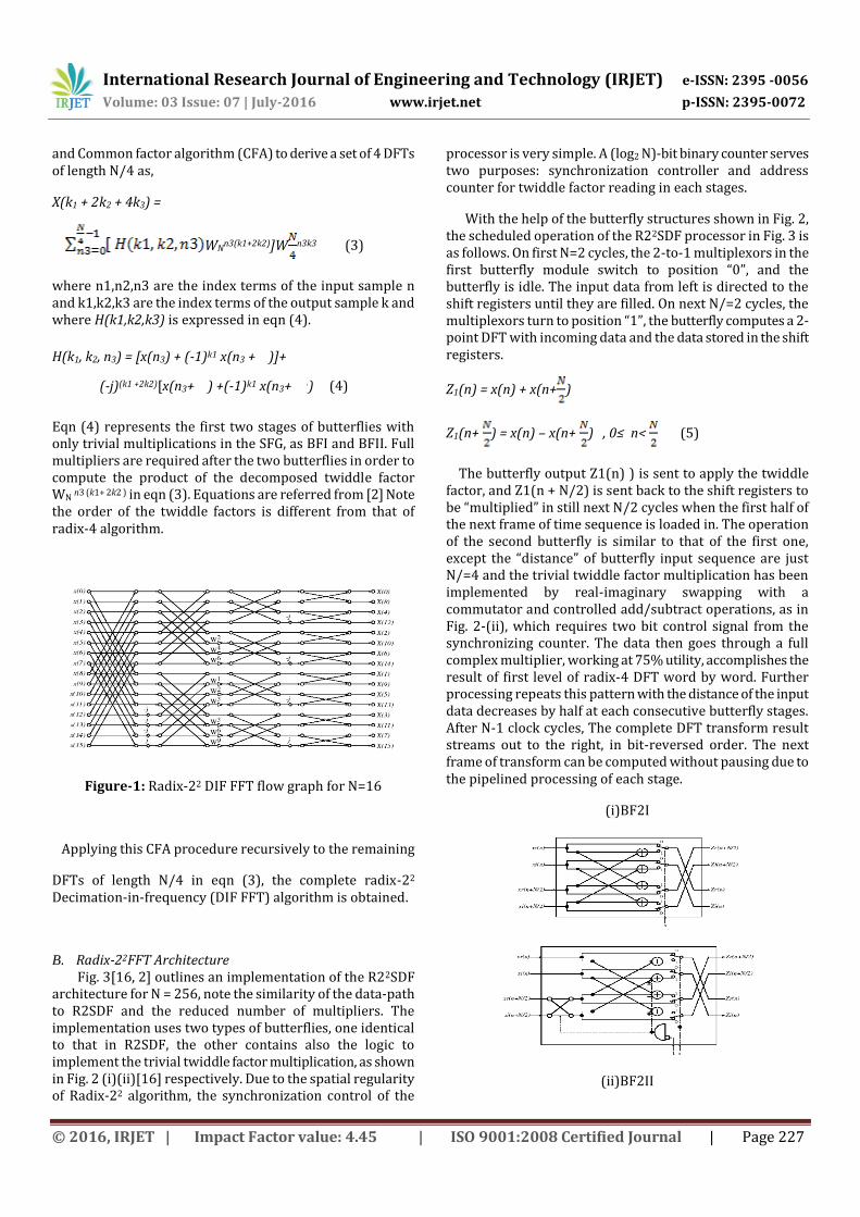
Figure-1: Radix-22 DIF FFT flow graph for N=16
Applying this CFA procedure recursively to the remaining
DFTs of length N/4 in eqn (3), the complete radix-22 Decimation-in-frequency (DIF FFT) algorithm is obtained.
B. Radix-22FFT Architecture Fig. 3[16, 2] outlines an implementation of the R22SDF architecture for N = 256, note the similarity of the data-path to R2SDF and the reduced number of multipliers. The implementation uses two types of butterflies, one identical to that in R2SDF, the other contains also the logic to implement the trivial twiddle factor multiplication, as shown in Fig. 2 (i)(ii)[16] respectively. Due to the spatial regularity of Radix-22 algorithm, the synchronization control of the
processor is very simple. A (log2 N)-bit binary counter serves two purposes: synchronization controller and address counter for twiddle factor reading in each stages.
With the help of the butterfly structures shown in Fig. 2, the scheduled operation of the R22SDF processor in Fig. 3 is as follows. On first N=2 cycles, the 2-to-1 multiplexors in the first butterfly module switch to position “0”, and the butterfly is idle. The input data from left is directed to the shift registers until they are filled. On next N/=2 cycles, the multiplexors turn to position “1”, the butterfly computes a 2-point DFT with incoming data and the data stored in the shift registers.
Z1(n) = x(n) + x(n+ )
Z1(n+ ) = x(n) – x(n+ ) , 0≤ n< (5)
The butterfly output Z1(n) ) is sent to apply the twiddle factor, and Z1(n + N/2) is sent back to the shift registers to be “multiplied” in still next N/2 cycles when the first half of the next frame of time sequence is loaded in. The operation of the second butterfly is similar to that of the first one, except the “distance” of butterfly input sequence are just N/=4 and the trivial twiddle factor multiplication has been implemented by real-imaginary swapping with a commutator and controlled add/subtract operations, as in Fig. 2-(ii), which requires two bit control signal from the synchronizing counter. The data then goes through a full complex multiplier, working at 75% utility, accomplishes the result of first level of radix-4 DFT word by word. Further processing repeats this pattern with the distance of the input data decreases by half at each consecutive butterfly stages. After N-1 clock cycles, The complete DFT transform result streams out to the right, in bit-reversed order. The next frame of transform can be computed without pausing due to the pipelined processing of each stage.
(i)BF2I
(ii)BF2II

International Research Journal of Engineering and Technology (IRJET) e-ISSN: 2395 -0056
Volume: 03 Issue: 07 | July-2016 www.irjet.net p-ISSN: 2395-0072
© 2016, IRJET | Impact Factor value: 4.45 | ISO 9001:2008 Certified Journal | Page 228
Figure-2: Butterfly structure for R22SDF FFT processor
In practical implementation, pipeline register should be inserted between each multiplier and butterfly stage to improve the performance. Shimming registers are also needed for control signals to comply with thus revised timing. The latency of the output is then increased to N-1 + 3(log4N-1) without affecting the throughput rate.
Figure-3: R22SDF pipeline FFT architecture for N = 256
3. IMPLEMENTATION OF FFT IN OFDM COMMUNICATION
SYSTEM
The fundamental principle of the OFDM system is to decompose the high rate data stream (bandwidth=W) into N lower rate data streams and then to transmit them simultaneously over a large number of subcarriers [11]. The IFFT and the FFT are used for, respectively, modulating and demodulating the data constellations on the orthogonal subcarriers [9].
Figure-4: OFDM Modem system
Figure 4 is the FFT based OFDM, the input digital data is processed by M- ary QAM modulator to map the data with N subcarriers that are implemented using the IFFT block. Quadrature amplitude Modulation (QAM) consist of serial input parallel output (SIPO) and mapping, input data serially given to SIPO with respect to clock high, and reset low, for each clock the input is transferred and appeared parallel at the output as in Fig 6, this is the input for mapping block, here with respect to the input location in the constellation graph is located and the 16 bit real and imaginary coefficients are given as output as shown in fig 7.
Figure-5: 16-QAM square constellation using Gray encoding.
(i)RTL schematics
(ii) output waveform Figure-6: SIPO results
(i)RTL schematics
(ii) output waveform Figure-7: Mapping results
Symbol generator used to generate a symbol of 64 bit using 16 bit as input from output of mapping, by concatenating 48 bit of inputs in 3 last clock cycle by considering reset bit.
Figure-8: Symbol Generator Results To make it 128bit 32 bit of zeros are concatenated to both
sides of the 64 bit input.
International Research Journal of Engineering and Technology (IRJET) e-ISSN: 2395 -0056
Volume: 03 Issue: 07 | July-2016 www.irjet.net p-ISSN: 2395-0072
© 2016, IRJET | Impact Factor value: 4.45 | ISO 9001:2008 Certified Journal | Page 229
Figure-9: Zero Padding Results
The cyclic prefix is actually a copy of the last portion of the data symbol appended to the front of the symbol during the guard interval. The cyclic prefix allows the data to be realigned at the receiver, thus regaining orthogonality. 128 bit output of the zero padding is given as input for IFFT, the output of IFFT is given to cyclic prefix as input
Figure-10: Cyclic prefix results
The Fast Fourier Transform (FFT) converts the signals from time domain representation to frequency domain representation and consequently the IFFT performs the reverse operation. Signals are processed in frequency domain due to simplified computation as compared to the time domain computation. These signals are converted back to time domain using IFFT block in order to reduce the number of backend RF-oscillators and demodulators.
Figure-11: IFFT results
Before transmitting the data are converted back to serial from parallel form and OFDM transmits a large number of narrowband carriers, closely spaced in the frequency domain. The available bandwidth in frequency is split into N sub-channels, one for each sub-carrier, where each has a power spectrum shape of a squared sinc pulse.
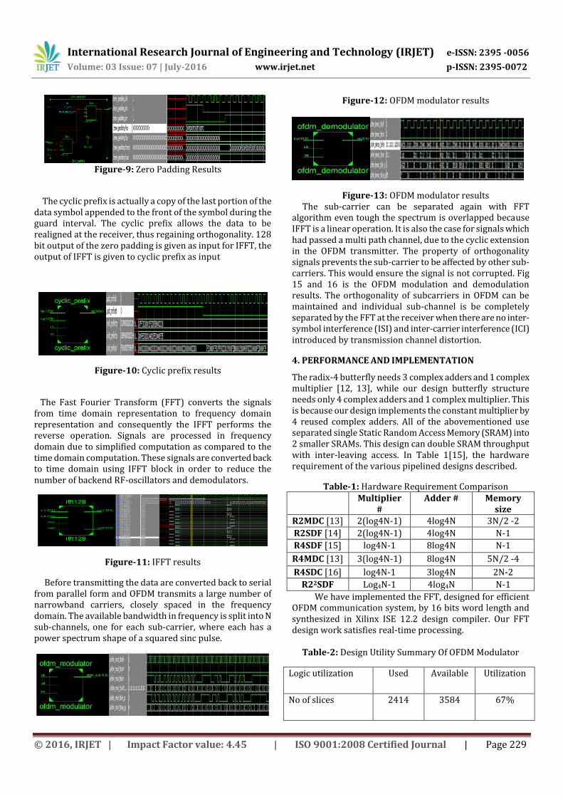
Figure-12: OFDM modulator results
Figure-13: OFDM modulator results The sub-carrier can be separated again with FFT algorithm even tough the spectrum is overlapped because IFFT is a linear operation. It is also the case for signals which had passed a multi path channel, due to the cyclic extension in the OFDM transmitter. The property of orthogonality signals prevents the sub-carrier to be affected by other sub-carriers. This would ensure the signal is not corrupted. Fig 15 and 16 is the OFDM modulation and demodulation results. The orthogonality of subcarriers in OFDM can be maintained and individual sub-channel is be completely separated by the FFT at the receiver when there are no inter-symbol interference (ISI) and inter-carrier interference (ICI) introduced by transmission channel distortion.
4. PERFORMANCE AND IMPLEMENTATION
The radix-4 butterfly needs 3 complex adders and 1 complex multiplier [12, 13], while our design butterfly structure needs only 4 complex adders and 1 complex multiplier. This is because our design implements the constant multiplier by 4 reused complex adders. All of the abovementioned use separated single Static Random Access Memory (SRAM) into 2 smaller SRAMs. This design can double SRAM throughput with inter-leaving access. In Table 1[15], the hardware requirement of the various pipelined designs described.
Table-1: Hardware Requirement Comparison Multiplier
# Adder # Memory
size R2MDC [13] 2(log4N-1) 4log4N 3N/2 -2
R2SDF [14] 2(log4N-1) 4log4N N-1
R4SDF [15] log4N-1 8log4N N-1
R4MDC [13] 3(log4N-1) 8log4N 5N/2 -4
R4SDC [16] log4N-1 3log4N 2N-2
R22SDF Log4N-1 4log4N N-1
We have implemented the FFT, designed for efficient OFDM communication system, by 16 bits word length and synthesized in Xilinx ISE 12.2 design compiler. Our FFT design work satisfies real-time processing.
Table-2: Design Utility Summary Of OFDM Modulator
Logic utilization Used Available Utilization
No of slices 2414 3584 67%

International Research Journal of Engineering and Technology (IRJET) e-ISSN: 2395 -0056
Volume: 03 Issue: 07 | July-2016 www.irjet.net p-ISSN: 2395-0072
© 2016, IRJET | Impact Factor value: 4.45 | ISO 9001:2008 Certified Journal | Page 230
No of slice flipflop 800 7168 11%
No of 4 input LUTs 4161 7168 58%
No of bonded IOBs 19 141 13%
No of MULT18X18s 12 16 75%
Table-3: Design Utility Summary Of OFDM Demodulator
Logic utilization Used Available Utilization
No of slices 1816 3584 50%
No of slice flipflop 1027 7168 14%
No of 4 input LUTs 2756 7168 38%
No of bonded IOBs 22 141 15%
No of MULT18X18s 6 16 37%
The design utilities of OFDM modulator and demodulators are in the table 2 and 3 from the simulation result. Further, we have implemented the FFT, designed for efficient mobile WiMAX, by 16 bits word length and synthesized in Xilinx ISE 12.2 design compiler.
5. CONCLUSIONS
We have a memory based recursive FFT design which has much less gate counts, lower power consumption and higher speed. The proposed architecture has three main advantages (1) fewer butterfly iteration to reduce power consumption, (2) pipeline of radix-22 butterfly to speed up clock frequency, (3) even distribution of memory access to make utilization efficiency in SRAM ports. In summary, the speed performance of our design easily satisfies most application requirements of Fixed 802.16d and Mobile 802.16e WiMAX, which uses OFDMA modulated wireless communication system. Our design also occupies lesser area, hence lower cost and power consumption.
REFERENCES
[1] Payaswini P and Manjaiah D.H “Analysis Of Effect Of Cyclic Prefix On Data Rates In Ofdm Modulation Techniques” International Journal of Advanced Computer and Mathematical Sciences ISSN 2230-9624. Vol 3, Issue 4, 2012, pp 465-470
[2] K. Harikrishna and T. R. Rao “FPGA Implementation of FFT algorithm for IEEE 802.16e (Mobile WiMAX)”International Journal of Computer Theory and Engineering, Vol. 3, No. 2, April 2011. ISSN: 1793-820
[3] Andrea M. Tonello, Salvatore D’Alessandro and Lutz Lampe “Cyclic Prefix Design and Allocation in Bit-loaded OFDM over Power Line Communication Channels” IEEE transactions on communications – preprint, june 2010
[4] S. He and M. Torkelson. A new approach to pipeline FFT processor, 10th Int. Parallel Processing Symp. (IPPS’96), p. 766–770, 1996.
[5] Digital Signal Processing: Principles, Algorithms and Applications (3rd Edition) by John G. Proakis and Dimitris K Manolakis - Prentice-Hall, Inc., - Oct 5, 1995.
[6] John F. Wakerly, “Digital Design Principles and Practices”, Pearson Education, 2006.
[7] Modelsim manual, http://support.xilinx.com.
[8] Xilinx, Inc. http://www.xilinx.com/.
[9] G. Bi and E. V. Jones, “A pipelined FFT processor for word sequential data”, IEEE Trans. Acoust., Speech, Signal Processing, 37(12):1982–1985, Dec. 1989.
[10] Xilinx, Inc. High-Performance 1024-Point Complex FFT/IFFT V2.0. http://www.xilinx.com/ipcenter/
[11] U. S. Jha and R. Prasad, “OFDM Towards Fixed and Mobile Broadband Wireless Access”, London: Artech House Inc., 2007.
[12] Chi-Hong Su and Jen-Ming Wu, “Reconfigurable FFT Design for Low Power OFDM Communication Systems”, Proc. of the 2006 IEEE 10th Intern. Symposium on Consumer Electronics (ISCE’06), 28 June - 1 July 2006, Russia, pp.1-4, 2006.
[13] Hui Liu and Guoqing Li, OFDM Based Broadband Wireless Networks, published by John Wiley & Sons, Inc., Hoboken, New Jersey, 2005.
[14] Dr.S.S.Riaz Ahamed “PERFORMANCE ANALYSIS OF OFDM” Journal of Theoretical and Applied Information Technology © 2008 JATIT. All rights reserved
[15] K. Harikrishna, T. Rama Rao and Vladimir A. Labay, “A RADIX 22 Pipeline FFT for Ultra Wide Band Technology”, International Conference on Computer & Network Technology (ICCNT), conference proceedings published by World Scientific Press,

International Research Journal of Engineering and Technology (IRJET) e-ISSN: 2395 -0056
Volume: 03 Issue: 07 | July-2016 www.irjet.net p-ISSN: 2395-0072
© 2016, IRJET | Impact Factor value: 4.45 | ISO 9001:2008 Certified Journal | Page 231
Singapore. Chennai, India, Jul 24-28, 2009.
[16] L.R. Rabiner and B. Gold. Theory and Application of Digital Signal Processing. Prentice-Hall, Inc., 1975.
[17] Angela DARIE, Ion BOGDAN “Pilot Symbol Assisted Modulation using 16-Level QAM for a Wireless System” Telecommunication Anul Lii, Nr. 1/2009