fpga rock band player -...
TRANSCRIPT
FPGA ROCK BAND PLAYER
A Design Project Report
Presented to the Engineering Division of the Graduate School
of Cornell University
in Partial Fulfillment of the Requirements for the Degree of
Master of Engineering (Electrical)
by
Jeffrey Yates and Thomas Gowing
Project Advisor: Bruce Land
Degree Date: May 2011

Abstract
Master of Electrical Engineering Program
Cornell University
Design Project Report
Project Title:
FPGA Rock Band Player
Authors:
Jeffrey Yates and Thomas Gowing
Abstract:
Rock Band 2 is a popular video game enjoyed by millions on their Xbox 360 console game systems. However, unlocking all of the available songs is a task that many players do not have time or patience for. In addition, many players wish they had talented players to achieve high scores with. We have designed a system that is able to beat Rock Band songs on any difficulty, playing up to four instruments at a time. Implemented on an FPGA, the design is capable of highly accurate, real-time results. Video is read directly from the Xbox without any external sensors mounted on the TV. Modifications were made to the Rock Band instruments that maintain their original functionality and wireless radios were used to allow users to play the game far away from the Xbox. Advanced detection algorithms allow this device to achieve near-perfect scores and compete with any human.

Table of Contents
1. Executive Summary............................................................................................................................................ 5
2. Design Problem and Requirements .................................................................................................................... 6
3. Possible Solutions and Related Work ................................................................................................................. 6
4. Chosen Solution and Specifications .................................................................................................................... 7
5. Division of Labor ................................................................................................................................................ 7
5.1 Jeff Yates ...................................................................................................................................................... 7
5.2 Tom Gowing ................................................................................................................................................. 8
6. Background Information .................................................................................................................................... 9
6.1 Rock Band .................................................................................................................................................... 9
6.2 The NTSC Video Standard............................................................................................................................ 10
7. High Level Design ............................................................................................................................................. 11
8. Implementation Details ................................................................................................................................... 12
8.1 Video Decoding .......................................................................................................................................... 12
8.2 Detection Overview .................................................................................................................................... 13
8.3 Guitar and Bass .......................................................................................................................................... 15 8.3.1 Detection Scheme ............................................................................................................................... 15
8.4 Drums ........................................................................................................................................................ 16 8.4.1 Detection Scheme ............................................................................................................................... 16
8.5 Vocals ........................................................................................................................................................ 18 8.5.1 Detection Scheme ............................................................................................................................... 18 8.5.2 Feedback Control System .................................................................................................................... 18 8.5.3 Sound Generation ............................................................................................................................... 19
8.6 Wireless Communication ............................................................................................................................ 20 8.6.1 Wireless Radios ................................................................................................................................... 20 8.6.2 Transmitting Data ................................................................................................................................ 21 8.6.3 Receiving Data ..................................................................................................................................... 23 8.6.4 Custom Circuit Board ........................................................................................................................... 23
8.7 Controller Modification ............................................................................................................................... 24
9. Design Process ................................................................................................................................................. 25
9.1 Designing and Implementation Timeline ..................................................................................................... 26
9.2 Cursor Module ............................................................................................................................................ 28
10. Results ........................................................................................................................................................... 29
11. Conclusions .................................................................................................................................................... 30
12. Future Work ................................................................................................................................................... 31
13. Special Thanks................................................................................................................................................ 31
14. References ..................................................................................................................................................... 31
15. Schematics ..................................................................................................................................................... 32
15.1 Transmitter Radio ..................................................................................................................................... 32
15.2 Receiver Board.......................................................................................................................................... 33
15.3 Controller Modification ............................................................................................................................. 34
16. Code............................................................................................................................................................... 35
16.1 Microcontroller Embedded Software ......................................................................................................... 35
16.2 FPGA ........................................................................................................................................................ 35

1. Executive Summary
Rock Band 2 is a video game played by millions across multiple platforms including the Xbox 360. Some play the game casually while others are looking to unlock content and beat high scores, both of which take a significant amount of time. To unlock new songs, the campaign mode must be completed, which can take many hours of concentration. Many people would like a way to unlock the songs without having to go through the entire game. Other players play the game in hopes of high scores and achievements, which can take even more time and be highly frustrating. Finally, there are players that wish they had more people to play with to fill their band.
The main problem we are addressing is designing a system that can play any song in Rock Band 2 without input from the user, allowing them to achieve higher scores, unlock songs, and play multiple instruments at a time. A major challenge is detecting notes scrolling on the screen more accurately than the human eye. Another challenge is timing the device correctly so the Xbox 360 receives the instrument inputs within the correct window to play the note successfully. Implementing accurate vocals without a human voice is another problem. Finally, another major challenge is being able to control the instruments wirelessly without destroying their functionality.
We have designed a fully automated Rock Band player implemented on an FPGA. Other implementations are only capable of playing one instrument, or require obstructive sensors to be attached to the television. Our design is capable of playing up to four players at the same time and makes its detection directly from the video output, so no external sensors are required. The device is capable of beating any song on expert and achieves competitive scores with all instruments. We use wireless radios along with microcontrollers to handle communication between the device and the instruments. We have modified the guitars and drums while still maintaining the functionality of the instruments when the device is not being used. We designed the device for testability, which included designing a separate cursor module to pinpoint pixel locations and their RGB values.
Our solution to note detection is to decode the video signal outputted by the Xbox 360 and send it to custom pixel detectors that can detect notes for each instrument. By exploiting the parallelism of an FPGA, we are able to instantiate many of these pixel detectors and run detection of every note in parallel all at the same time. Advanced conditions and color thresholds allow us to filter out background colors and potential false note triggers. Syncing with the video frame rate and inserting delays where appropriate allows us to meet timings required by the Xbox 360.
We handle the vocals by direct digital synthesis of a single frequency sound wave binned to 12 notes within a single octave. The sound is outputted from speakers and picked up by the unmodified Xbox Microphone. Other instruments were wired with optocouplers in parallel with the existing buttons to maintain original functionality. Radios were used as a means to send commands to the different instruments. A custom printed circuit board (PCB) was designed and printed to house the receiving radios and the microcontrollers that control the optocouplers. This solved the issue of wirelessly controlling the instruments with the FPGA.
With our device we are able to achieve high accuracies for all instruments playing simultaneously. The drums and guitars average 98% accuracy while the vocals average 77%. The Rock Band Player can handle any song on expert and consistently achieves these averages. We met our original design specifications with impressive accuracy. Future work can be done to improve detection, package the hardware more neatly, and improve the user interface. This project was a great learning experience and required knowledge of several ECE topics covered in our undergraduate and graduate studies.

2. Design Problem and Requirements
The overall problem and motivation for this project is to allow Rock Band 2 players to beat songs, achieve high scores, and unlock new material without having to do anything but turn on a device. There are several challenges associated with this goal including note detection, simulating human vocals, meeting the required timings, and communicating with the Xbox 360 without destroying any hardware.
The device must detect incoming notes on the screen. The first challenge associated with this is how to detect any video signal coming out of the Xbox. How do we convert the video output of the Xbox into digital data that the device can analyze? Once the device has the data, the next problem is deciding how the device will determine what is a note and what is just background color. Once a note is detected, it must be played at the appropriate time to meet the timing window that Rock Band requires. There are real-time deadlines that constrain how long the device has to calculate and also when it should send signals to be received by the Xbox at the right time.
Another problem is how the device should communicate with the Xbox 360 to actually play the game. Should the device directly communicate with the Xbox or should it communicate with the instruments. The decision had to be made whether to use wireless or direct connection for communication. If modifying instruments was necessary, we needed to find out what circuitry would simulate button presses without destroying the controller. We also needed to find a way to simulate human vocals.
3. Possible Solutions and Related Work
To convert the Xbox 360’s video output into digital data that the device can analyze we could either read off the monitor display or convert the video signal that comes directly out of the Xbox 360. We saw several implementations on the internet that use photo sensors that are put directly in front of the TV screen to detect notes [3]. The sensors must be positioned exactly where notes pass through on the screen. Another solution is to take the NTSC video directly from the Xbox and analyze it. One way of doing this is by counting horizontal sync signals to locate different lines and analyze the video signal voltage to detect a bright note using a comparator. This was done by two groups using microcontrollers [1][2]. A third option is to take the NTSC signal and convert it to digital RGB values to get accurate color information of any pixel on the screen.
Analyzing the incoming video data can be done on several different devices. One group has used a computer to analyze the data and apply threshold comparisons [3]. Other groups have used microcontrollers along with voltage comparators to determine when a note has been detected [1] [2]. Another option is to use an FPGA to do all the detection in hardware. Software detection is unable to take advantage of parallel pixel detections and may have trouble meeting the real-time deadlines of the game. A hardware implementation may require a lot of hardware to cover all possible cases of note detection.
There were several options considered for communication with the Xbox 360. We originally wanted to communicate directly with the Xbox using a wireless protocol. Most other implementations we saw required modification of the instruments using transistors as switches to simulate button presses. One group has wired them up in parallel so the existing buttons remain functional [1]. We had to consider the options of directly connecting the FPGA with these modified controllers or trying to wirelessly communicate with them.
Another group at Cornell was working on the Rock Band Vocals at the same time we were. They are using direct digital synthesis to create single frequency sounds that the microphone picks up and

treats like human voices [2]. Another option was to create an electrical signal to feed into the Xbox or microphone without making any sound at all.
4. Chosen Solution and Specifications
Ultimately we chose to decode the NTSC coming directly out of the Xbox 360 with a TV decoder chip. We didn’t want the mess and screen obstruction caused by placing photo sensors in front of the TV. Also, we wanted the precision of knowing 10-bit RGB values for any pixel to fine tune our detection with. We also chose to implement this device on an FPGA to exploit the parallelism in pixel detection to meet the timing deadlines. Being hardware engineers, we wanted to design hardware more than software and wanted more experience with Verilog. There are also several other components on the FPGA development board including the TV Decoder, VGA DAC, SDRAM, and an Audio CODEC. We didn’t think that microcontrollers would be able to handle detection for all 4 instruments simultaneously.
We learned that the Xbox 360 has a proprietary wireless protocol that we didn’t have access to, which ruled out the possibility of wirelessly communicating with it. We chose to modify the instruments with optocouplers which simulate pressing a button well. We wanted to be able to wire it up in parallel so the instruments would remain functional without use of the device. Ultimately we decided to use wireless communication from the FPGA to the modified instruments so we could spread the instruments around and reduce the number of connections to the FPGA. We also wanted to gain some experience using the wireless radios and interface them with microcontrollers. As for the vocals we decided to do DDS on the FPGA and output to a speaker instead of sending an electric signal to the microphone because we didn’t have the datasheet for the microphone and didn’t know what the characteristics of the signal were. In addition, we thought it would be fun for users to hear the device change the frequency of the output tone along with the music.
After addressing these different challenges with our planned solution, we came up with some specifications for our device:
1. It must be capable of playing all four instruments at the same time 2. It should be able to play any song on expert difficulty without changing any settings 3. It must take the video directly from the Xbox and not require obstructive photo sensors 4. It must use the existing controllers to play the game 5. The instruments must not be damaged in anyway and remain fully functional 6. Wireless communication will be used to send commands from the FPGA to the instruments 7. The device must meet timing deadlines of the game in order to successfully play notes in
real-time 8. The accuracy of the device must be competitive with at least an average Rock Band player
5. Division of Labor
Being a group of two, we tried to split up the work load as evenly as possible into tasks that could be worked on in parallel and interfaced with each other easily. We were both responsible for very specific components of the design.
5.1 Jeff Yates
Controller modification: The Rock Band guitars and drums needed to be modified to be controllable by electric signals coming from the microcontrollers. This had to be done without destroying the controllers in any way so that the instruments could be used without the device. This task included disassembling the controllers, soldering circuitry in parallel with the existing buttons, and designing a way to electrically control the switches. All three instruments were

successfully modified and allowed us to communicate with the Xbox by electronically controlling the instruments. The implementation details are covered in Section 8.7.
Custom printed circuit boards: Custom circuit boards needed to be designed to house the receiving radio, microcontroller, and optocoupler circuitry for each of the three modified instruments. All of the circuitry needed to fit on a specific size dual-layered circuit board. This task included designing the circuitry required for each board, laying out the components using ExpressPCB software, populating and soldering each board and testing each as well. A lot of time was spent in layout to make sure everything would fit and function because no testing software was available to guarantee functionality. All three boards completely worked and were used in the final implementation. The custom circuit board design is covered in Section 8.6.4.
Wireless communication: A way of communicating wirelessly from the FPGA to the instruments had to be designed and tested. Radios had to be selected, wired up, programmed and tested. A module on the FPGA was designed to send data to the transmitting radio at the correct baud rate and alternate instrument updates to share bandwidth evenly. Microcontrollers were programmed to receive incoming data and recognize when the FPGA was trying to send data to its specific instrument. There was a large amount of testing and debugging associated with getting the radios to work. In the end four radios were used and all successfully transmitted and received data to update the instruments with. Wireless communication is discussed in detail in Section 8.6.
Synthesis of sound for vocals: Sound needed to be synthesized according to desired pitch detected by the detection architecture. The sound needed to be the correct frequency and compatible with the Rock Band microphone to simulate a human vocalist. A control loop was designed to change pitch according to differences between desired and current pitch. Direct digital synthesis and discrete tone frequencies were programmed into the FPGA. This module interfaced with the vocal detection module and outputted signals from the FPGA to the speakers. The digital synthesis and control loop worked and allowed solid performance from the vocals in the final implementation. More vocal implementation details are discussed in Section 8.5.
5.2 Tom Gowing
Detection architecture for all instruments: For each instrument, the incoming pixels needed to be analyzed to determine if a note is detected. Modules were designed to look at a single pixel at a specific location and compare its RGB color values to thresholds that were chosen to match specific notes. These modules were grouped together into larger detectors and positioned carefully across the screen. A lot of time was spent in perfecting the detection conditions for each note and filtering out any background color or flashes on the screen. The detection scheme was optimized enough to achieve 98% detection accuracy in the final implementation. Detection details are covered in Section 8.2 and specifically for each instrument in Sections 8.3, 8.4, and 8.5.
Control and timing for drums and guitar: Control logic was needed to properly time when notes were sent to the instruments and picked up by the Xbox. A buffer was designed to store notes as they are detected until they needed to be strummed to trigger properly in the game. The buffer also required logic to determine when to merge multiple detections of the same note together or when to strum different notes at the same time. Modules were designed to hold notes on the instruments for appropriate amounts of time required for detection by the Xbox. Different modules were designed to simulate guitar strumming, kick pedal hitting, and pressing frets on the guitars. A lot of time was spent adjusting timings to land within the timing windows that the game required. The final control logic and timings were good enough to achieve high accuracy in the final implementation. Instrument control details are discussed in Sections 8.3, 8.4, and 8.5.
Cursor module for testing and debugging: A cursor module was needed to freeze the screen and determine the location and RGB values of any pixel on the screen. This required interfacing with the video decoder and extracting pixel location and color. The module also needed to draw pixels on the screen to aid in positioning the detectors. This module was crucial in testing and debugging the detection thresholds and positioning for each instrument. The cursor module is discussed in Section 9.2.
6. Background Information
Before a detailed description of our design is possible, an understanding of both Rock Band and the NTSC Video Standard is required. These two topics are crucial in our detection algorithms and the overlying project goals in general.
6.1 Rock Band
Rock Band is a video game that can be played on several different gaming consoles. We have chosen to focus on the Xbox 360 version of the game, as that is the console that we currently own. The game is in a sense a musical puzzle game where the user has to press the correct sequence of notes on a given instrument at the correct time to score points and move on to later levels. Music is played in the background and the notes to be played match the sounds being made by the instrument, so the player is essentially playing along with the music. Up to four people can play at a time, each with a different instrument (drums, guitar, vocals, or bass guitar). When playing together, the different players form a band and can tour around a virtual world playing different set lists of songs that are popular in real life.
The object of the game is to play as many notes correctly in a row as possible. Points are awarded when correct notes are played. Multipliers can be added once the player has hit several notes in a row, which is called a streak. Special notes that appear blue can be played to accumulate star power. Once star power is activated, a 2x multiplier is given on top of any existing multipliers. Players can fail a song if they do not play enough notes correctly or play notes at incorrect times. An initial number of songs can be chosen from and more can be unlocked after beating the game. To beat the game, a player must advance through a campaign of increasingly difficult songs, played at different venues across the world.
The physical layout of the game interface is straightforward. The Vocals are located along the top of the screen while from left to right are the Guitar, Drums, and Bass fret board runways where the notes scroll down. At the bottom of the runways is a bar indicating when the notes must be played. Each note has its own vertical column except for the bass drum pedal, which spans horizontally across 4 note columns. Along the Vocals runway are notes with different heights corresponding to different pitches that must be sung. The lyrics to be sung are listed along the bottom of the runway. The current pitch being sung is denoted by the arrow. The user must try to match the height of the arrow to the height of the incoming lines.
Playing the instruments is very intuitive. To play the guitars, the user must first press the fret buttons and then strum when the note must be played. This simulates a guitarist pressing a finger against a string before strumming with a pick. The drums must be hit by a stick and require no strum signal. The bass drum is hit by a separate foot pedal. The vocals are controlled by a microphone that you sing into.

Figure 1: Screenshot of the 4 player Rock Band interface (courtesy of IGN.com)
There are several features that make accurate video pixel detection tricky. In the background there is an animated concert taking place, which can shine through the fret board runways and interfere with color detection, causing false positives. Additionally, there are star power notes that are a different color than normal notes. When the star power is activated, the fret boards turn different colors, which often interfere with detection. Held notes have long tails after the note that can easily be confused with a new note. Hammer-on notes are smaller and have 2 white stripes on them, which can make detection harder.
6.2 The NTSC Video Standard
The Xbox 360 outputs video over a composite cable that adheres to the NTSC Video standard. Each frame of NTSC video has 525 horizontal lines, 486 of which make up the visible video raster. The frames are interlaced such that every other line is refreshed during a frame refresh. Refreshes occur at about 60Hz but only update every other line of the screen, so an entire screen refresh occurs at about 30Hz.
Each line that is drawn begins with a low pulse called an HSYNC pulse to synchronize the horizontal trace across the screen. These pulses can be counted to tell what line is being drawn. After the HSYNC is the Back Porch burst which is used to synchronize the receiver to the frequency of the chrominance sub-carrier frequency. Finally, after the Back Porch is the video signal. The video signal is comprised of luminance (black and white) and chrominance (color) components. Originally there was only black
Figure 2: Image of NTSC Video interlaced refresh scheme

and white, but later color was added on a sub-carrier to maintain backwards compatibility. After half of the lines have been drawn, a VSYNC pulse is received, signifying the start of a new frame. A lot of our circuitry uses a new frame signal to update detection values.
Figure 3: Timing diagram of a typical NTSC horizontal line trace
7. High Level Design
Our design is split into multiple components, each with a very specific task. The Xbox 360 is responsible for running the Rock Band 2 software as well as outputting composite video and taking input data from the four instruments. The video decoder chip exists on the DE2 development board along with the FPGA. The FPGA handles note detection, output control logic, and sound synthesis. Also on the DE2 is the audio codec, which converts the digitally synthesized sound to an analog signal that can be played on normal speakers. On a separate solder board next to the FPGA is the wireless transmitter used to send update commands to the guitar, bass, and drums. Each of these instruments has its own wireless receiver radio and microcontroller mounted on a custom PCB to receive commands and control the button presses of the instrument. The Xbox microphone is placed near the speakers to pick up the synthesized tones outputted by the speakers. All instruments are linked back to the Xbox input ports either by Xbox's proprietary wireless protocol or by a cable. A block diagram of the design is shown in Figure 4.
First, video is sent from the Xbox 360 to the DE2 on-board video decoder chip via composite cable. Here the analog NTSC signal is converted into a digital signal that can be further converted into the RGB color space within the FPGA. There is a separate module in the FPGA for each of the four instruments. Each instrument module receives the current pixel RGB data along with the location of the pixel on the screen.
Within each module, the pixel location and color data is used to detect notes at specific points on the screen according to specifically chosen color thresholds. There are several hardware modules dedicated to detecting the different notes that are encountered in the game. For the guitar and drums, notes are detected well before they actually need to be strummed to avoid flashing effects near the bottom of the screen that may cause false triggering. Because of this, we must store the notes in a FIFO buffer until they are ready to be committed and sent out to the instruments. Once outside of the buffer the guitars will determine what buttons should be pressed using the Fret Presser module and when to strum using the Strummer module. The Drums do not need to strum but instead need to hit the drums and pedal, which is taken care of by the Drum Hitter and Pedal Player respectively. For the Vocals, detection occurs in two places to determine the desired pitch

and the current pitch of the synthesized tone. A feedback control loop is used to make adjustments to the current pitch to properly match it with the desired pitch. This updates an increment used by the DDS to create digital sound waves.
Figure 4: High level block diagram of rock band player
The digital sound is sent to the on-board audio codec on the DE2 which converts it to analog and outputs it to a set of speakers. The microphone is placed near the speakers to pick up the sound and send it to the Xbox. The other instruments rely on commands sent wirelessly. Outputs of the guitar, bass and drums modules are sent to a Wireless module that sends data bit by bit to a wireless radio transmitter. Each of those instruments has its own wireless receiver to receive the command and send it to a microcontroller that is mounted along with the radio on a PCB. The microcontrollers control optocouplers that are wired in parallel to the physical buttons on the instruments, which allow them to simulate button pushes while also maintaining the original functionality of the buttons. The instruments are attached to the Xbox 360 and feed it input data needed for the Rock Band 2 game.
8. Implementation Details
This section will cover all of the logic implemented on the FPGA as well as the wireless transmitter and receivers, the custom circuit board, and the modified instruments.
8.1 Video Decoding
The video signal outputted from the Xbox 360 undergoes several stages of decoding before it can be analyzed by our detection modules and outputted to the monitor as a VGA signal. The Xbox 360 outputs video as NTSC standard video over a composite cable. On the DE2 development board there is a video-in port that accepts composite cables. This port leads directly to the ADV7181 TV Decoder chip that exists on the DE2 board external to the FPGA. Its function is to convert the analog
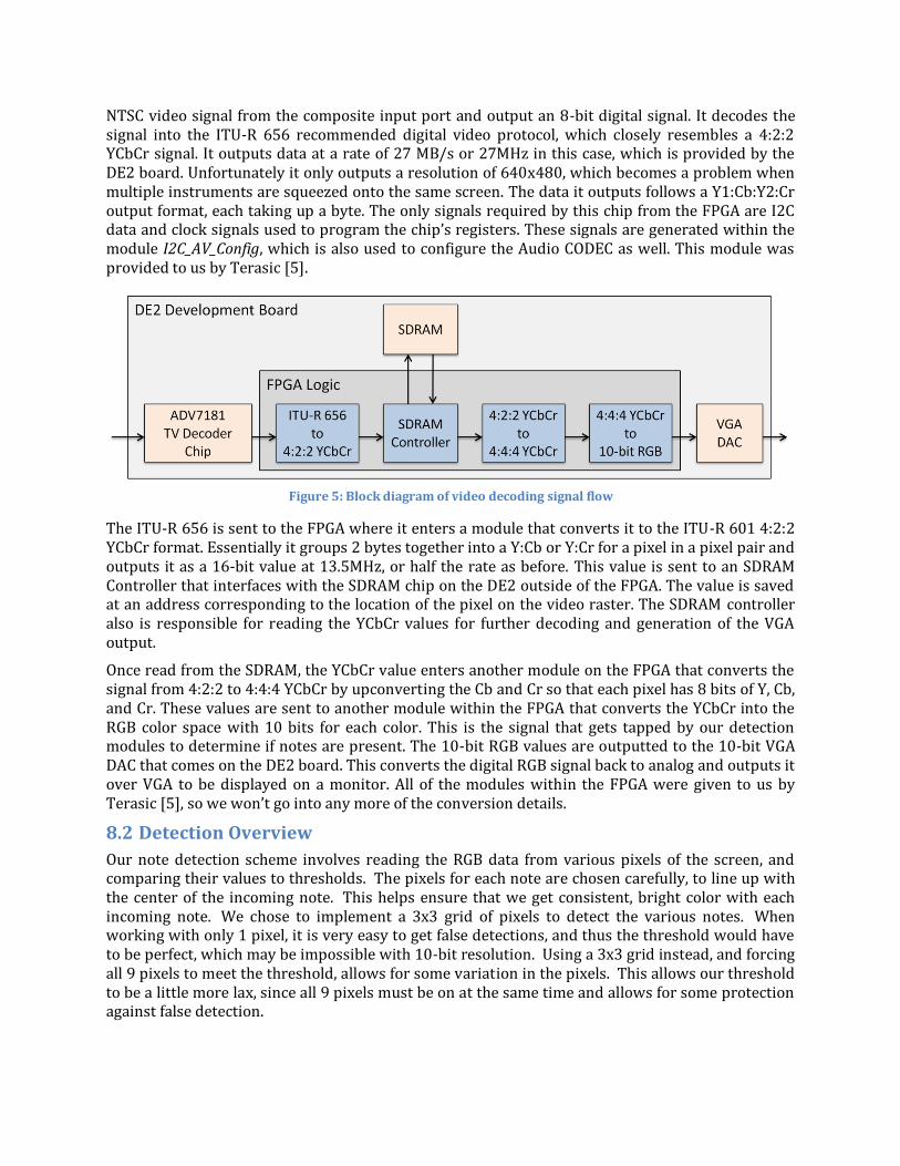
NTSC video signal from the composite input port and output an 8-bit digital signal. It decodes the signal into the ITU-R 656 recommended digital video protocol, which closely resembles a 4:2:2 YCbCr signal. It outputs data at a rate of 27 MB/s or 27MHz in this case, which is provided by the DE2 board. Unfortunately it only outputs a resolution of 640x480, which becomes a problem when multiple instruments are squeezed onto the same screen. The data it outputs follows a Y1:Cb:Y2:Cr output format, each taking up a byte. The only signals required by this chip from the FPGA are I2C data and clock signals used to program the chip’s registers. These signals are generated within the module I2C_AV_Config, which is also used to configure the Audio CODEC as well. This module was provided to us by Terasic [5].
Figure 5: Block diagram of video decoding signal flow
The ITU-R 656 is sent to the FPGA where it enters a module that converts it to the ITU-R 601 4:2:2 YCbCr format. Essentially it groups 2 bytes together into a Y:Cb or Y:Cr for a pixel in a pixel pair and outputs it as a 16-bit value at 13.5MHz, or half the rate as before. This value is sent to an SDRAM Controller that interfaces with the SDRAM chip on the DE2 outside of the FPGA. The value is saved at an address corresponding to the location of the pixel on the video raster. The SDRAM controller also is responsible for reading the YCbCr values for further decoding and generation of the VGA output.
Once read from the SDRAM, the YCbCr value enters another module on the FPGA that converts the signal from 4:2:2 to 4:4:4 YCbCr by upconverting the Cb and Cr so that each pixel has 8 bits of Y, Cb, and Cr. These values are sent to another module within the FPGA that converts the YCbCr into the RGB color space with 10 bits for each color. This is the signal that gets tapped by our detection modules to determine if notes are present. The 10-bit RGB values are outputted to the 10-bit VGA DAC that comes on the DE2 board. This converts the digital RGB signal back to analog and outputs it over VGA to be displayed on a monitor. All of the modules within the FPGA were given to us by Terasic [5], so we won’t go into any more of the conversion details.
8.2 Detection Overview
Our note detection scheme involves reading the RGB data from various pixels of the screen, and comparing their values to thresholds. The pixels for each note are chosen carefully, to line up with the center of the incoming note. This helps ensure that we get consistent, bright color with each incoming note. We chose to implement a 3x3 grid of pixels to detect the various notes. When working with only 1 pixel, it is very easy to get false detections, and thus the threshold would have to be perfect, which may be impossible with 10-bit resolution. Using a 3x3 grid instead, and forcing all 9 pixels to meet the threshold, allows for some variation in the pixels. This allows our threshold to be a little more lax, since all 9 pixels must be on at the same time and allows for some protection against false detection.

Our group of 3x3 pixel detectors is lumped into a hierarchical stage called the Grid Detector. This module is then instantiated 5 times for each guitar (since there are 5 notes) and 4 times for the drums (the drums 5th note is replaced by the bass pedal). The grid detectors are further grouped into a bar detector, as can be seen in Figure 6. This hierarchy is useful in the logical organization of the signals, and to group the pixel detectors by which color they are looking for.
We place our detectors about halfway up the screen. This is to allow for signal processing time, before we send the signals off to the instruments, and for correctness. We initially tried sampling the screen much closer to where the notes are played. Unfortunately we encountered problems due to the graphical effects of the note strike. When notes are played, they explode with bright color, and send ripples emanating outwards. These effects proved detrimental to our detection, so we moved the detection away from the note playing effects.
Because of this, we need to buffer the results of our detection, since we may be detecting more than one note (or chord) before we send the signal off to the instrument for playing. We made a circular buffer with 16 entries, which we deemed was more than enough for this purpose. The buffer has a head pointer and a tail pointer, which are both initialized to zero. When we add an element, we add it at the tail pointer, and increment the tail. When we read out an element, we read from the head pointer, and then increment the head. When the head pointer and the tail pointer are equal the queue is empty (it is too large to fill up) and we signal to other modules that any data that it may be seeing in the buffer is invalid. The buffer stores both the values of the notes that were detected, and the frame that they should be sent to the instrument on. This can be seen in the block diagram below.
This buffer is essential to the operation of our system. The frame number that is stored along with the notes is based off of a counter. This counter is an 8-bit counter, which ensures that it will only overflow every 256 frames. The number stored in the buffer is the current frame count at the detection plus a delay offset. This offset was experimentally determined to be 20 frames. We determine when new frames occur using a special module, aptly called NewFrame. This module monitors the current pixel coordinates of the input
stream, and pluses a signal every time those coordinates are (0,0). Since this only happens once per frame, this signifies a new frame to the rest of the hardware.
A key feature of our buffer is that it allows for merging of entries. It is possible that a chord (more than one note played together) could have the different notes involved be detected on different
Figure 6: Diagram of bar detector module which contains multiple pixel detector modules
Figure 7: FIFO buffer that stores notes and frame count

frames. In this case, we want to merge these entries into one. We have our buffer arranged so that an entry that is less than 3 frames in difference from the last frame written will be merged with the previous entry. This allows for chords where the notes are detected in adjacent frames to be played correctly as one chord.
The two major pieces of our detection scheme described above, namely the bar detector and the circular buffer, differ slightly between guitar and drum applications. The pictures drawn show the guitar application of these modules. The differences will be explained in the sections to come, where we dive into more detail about the instrument specific detection. The outputs from the buffer are monitored by instrument specific modules, which then processes the information before sending it to the wireless transmitter (to the instruments). These instrument specific modules will be discussed in detail below. The vocal detection is very different from the guitar, bass, and drum detection scheme, and will be described in detail in its own section of this report.
8.3 Guitar and Bass
The guitar and bass modules are lumped together because they are identical in every way, except for where they are located. Nothing differs between the guitar and bass in terms of detection, we simply look at different places on the screen, and send the information to a different physical instrument.
8.3.1 Detection Scheme
The detection starts with the pixel detector. This is where the threshold value is compared. The pixel detector has an input that tells it which color it is looking for, and it applies the appropriate threshold. If the RGB value of the pixel meets the requirements of the threshold, then a logic high is output through the oColor signal. The oColor signals from the various pixel detectors are then ANDed together inside of the Grid Detector to give an output for the detection of the note, since all pixel detectors are required to meet the threshold for a valid detection. An interesting modification that we had to make here was the introduction of what we have called the “wingman.” This is one extra pixel of detection that is situated outside of the normal 3x3 grid. This was put in to combat a problem we were seeing where notes that were supposed to be held were being seen as multiple notes.
Held notes have a tail coming out of the center of them that continues up the screen for as long as the note is held. Unfortunately, Rock Band tries to make this look cool, and it ripples somewhat. This causes our detectors to detect the note, then lose the detection in the rippling tail, but later regain it (believing it is a new note) and then strum, losing the held note and killing the streak multiplier. We solve this problem by introducing the wingman. The wingman is set some distance between 4 and 8 pixels away from the center of the main 3x3 grid. This pixel will detect the color when a note is present, but is far enough away from the tail of a held note, that it will not detect the tail. Since all 10 pixels are required to pass the check in order for a detection to be triggered, we will avoid false detections due to the note’s tail.
Unfortunately for us, solving this problem created another one. There are special notes in Rock Band called “hammer-ons” that can be played without requiring a strum of the guitar. These notes are designed differently so that a human player can distinguish them from the regular notes. The hammer-ons have a smaller amount of color, and bolder white edges. For hammer-on notes, the wingman does not pass through the colored portion of the note, it passes through the white edge. This requires a special case in our detection to detect this white edge. Adding in a special detection for this case was not a big problem, since this white case only occurs in a valid note.
Finally, we have the issue of “star power” or “overdrive” notes. These notes are special because they are white, instead of their usual color. If all of these notes are hit in succession, then the player

is awarded with power that can increase their streak multiplier. Similar to how we handled the hammer-ons, there is a special detection case for these notes. This is done in parallel with the standard detection, and is then combined with the standard output via an OR gate. This allows all color cases to be overwritten by the special detection if necessary.
Figure 8: Interactions between FIFO buffer, FretPresser, and Strummer modules
When a new valid note is detected it is store in our FIFO buffer, with a calculated delay, as described above. Then there are two instrument specific modules, FretPresser and Strummer, that constantly monitor the head of the buffer. The FretPresser is responsible for sending the signals that press the 5 fret buttons on the guitar. This module monitors the head of the buffer, and sends the new signals when the current frame count is 2 less than the stored frame count. We send the fret signals 2 frames earlier than the strum to eliminate any race conditions. The Strummer monitors the buffer and sends a strum signal when the current frame count is equal to the stored frame count. It then sends a signal to the buffer to indicate that the value was read, and the head pointer can be incremented. The fret signals are held constant until there is a new value to be sent, but the strum signal is sent as a pulse. The strum is held high for 2 frames, since only holding it for one frame caused the XBOX to occasionally miss the signal, and thus miss the note. This is likely due to the fact that the game is meant to be played by a human, and humans don’t strum at 60 Hz. Holding the strum value for 2 frames eliminated this problem. The interactions between the buffer, FretPresser, and Strummer are illustrated in Figure 8.
8.4 Drums
The operation of the drum detection scheme is very similar to the guitar detection scheme. There are a few minor differences though, such as the fact that there are now only 4 “notes” to represent the 4 drum pads. There is also the inclusion of the bass pedal, which is represented by an orange line that spans the area of all 4 notes. These changes will require slight modifications to the various modules described above, but their overall functionality remains nearly unchanged.
8.4.1 Detection Scheme
The pixel detection for the drums is very similar to that of the guitar, except for the addition of the pedal detection. Each pixel detector must check for both its assigned note color, and for the pedal. This requires an additional output bit for the pedal check. At the grid detector level, we now have two output signals as well, one being the AND of the note checks, and the other being the AND of the pedal checks. Since there is no such thing as a held note for the drums, there is no need for the wingman that we use in the guitar scheme. Therefore we have only 9 pixels per note in the drum detection. Also, there are no hammer-ons in the drums, so we need no special cases to detect for them. However there still are “star power” notes, and the special detection for those cases is carried out similarly in the drums as it was in the guitar module.
Detecting the pedal is not difficult, it just requires a separate threshold and a separate output. The interesting logic with regards to the pedal is determining if there is a valid pedal. There are a few different cases where the pedal will need to be hit. All 4 grid detectors could detect a pedal, or 3 could detect pedal and 1 detect a note, or 2 pedals and 2 notes. This is because there are cases when you can hit up to 2 pads along with the pedal. To solve this problem we OR our pedal output with the color detection at the pixel detector level. This way, all the way through the hierarchy, the pedal signal will be active high if the detector saw a pedal or a note. With this OR already done at a low level, when we are deciding to send a pedal signal to the controller or not, all we must do is AND the 4 pedal signals together.
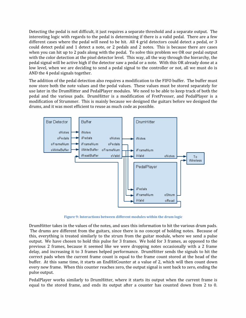
The addition of the pedal detection also requires a modification to the FIFO buffer. The buffer must now store both the note values and the pedal values. These values must be stored separately for use later in the DrumHitter and PedalPlayer modules. We need to be able to keep track of both the pedal and the various pads. DrumHitter is a modification of FretPresser, and PedalPlayer is a modification of Strummer. This is mainly because we designed the guitars before we designed the drums, and it was most efficient to reuse as much code as possible.
Figure 9: Interactions between different modules within the drum logic
DrumHitter takes in the values of the notes, and uses this information to hit the various drum pads. The drums are different from the guitars, since there is no concept of holding notes. Because of this, everything is treated similarly to the strum from the guitar module, where we send a pulse output. We have chosen to hold this pulse for 3 frames. We hold for 3 frames, as opposed to the previous 2 frames, because it seemed like we were dropping notes occasionally with a 2 frame delay, and increasing it to 3 frames helped performance. DrumHitter sends the signals to hit the correct pads when the current frame count is equal to the frame count stored at the head of the buffer. At this same time, it starts an EndHitCounter at a value of 2, which will then count down every new frame. When this counter reaches zero, the output signal is sent back to zero, ending the pulse output.
PedalPlayer works similarly to DrumHitter, where it starts its output when the current frame is equal to the stored frame, and ends its output after a counter has counted down from 2 to 0.
PedalPlayer is also responsible for signaling to the buffer that a value has been read, similar to how Strummer worked for the guitar module. There is a little bit of trickery here however, because we still need to signal that the value was read even if it is not a valid pedal. This is done by always signaling that the value was read, but only outputting the strum and starting the hit counter if the pedal was valid. This check is done within PedalPlayer, by ANDing the 4 pedal bits from the buffer. If all 4 bits are active, then we have a valid pedal, and must output the signal to the wireless module, and start the countdown timer. The interactions between the various modules can be seen in Figure 9.
8.5 Vocals
The vocal detection scheme is vastly different from the scheme for both the drums and the guitars. Since our vocal circuit is a feedback loop, we have two strips of detecting pixels. One strip detects the current output pitch, while the other detected the desired output pitch. Using the information from these two strips, we can adjust our pitch accordingly. We generate the output tones using a Direct Digital Synthesis (DDS) method. The different DDS increments are stored in a 12 entry look-up table (LUT), which is addressed by a variable level. This level is changed or kept constant based on the information from the two strip detectors.
8.5.1 Detection Scheme
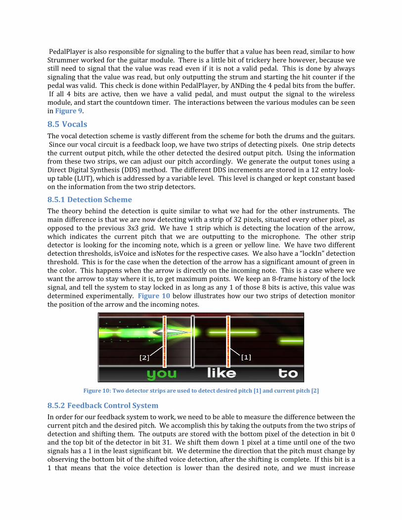
The theory behind the detection is quite similar to what we had for the other instruments. The main difference is that we are now detecting with a strip of 32 pixels, situated every other pixel, as opposed to the previous 3x3 grid. We have 1 strip which is detecting the location of the arrow, which indicates the current pitch that we are outputting to the microphone. The other strip detector is looking for the incoming note, which is a green or yellow line. We have two different detection thresholds, isVoice and isNotes for the respective cases. We also have a “lockIn” detection threshold. This is for the case when the detection of the arrow has a significant amount of green in the color. This happens when the arrow is directly on the incoming note. This is a case where we want the arrow to stay where it is, to get maximum points. We keep an 8-frame history of the lock signal, and tell the system to stay locked in as long as any 1 of those 8 bits is active, this value was determined experimentally. Figure 10 below illustrates how our two strips of detection monitor the position of the arrow and the incoming notes.
Figure 10: Two detector strips are used to detect desired pitch [1] and current pitch [2]
8.5.2 Feedback Control System
In order for our feedback system to work, we need to be able to measure the difference between the current pitch and the desired pitch. We accomplish this by taking the outputs from the two strips of detection and shifting them. The outputs are stored with the bottom pixel of the detection in bit 0 and the top bit of the detector in bit 31. We shift them down 1 pixel at a time until one of the two signals has a 1 in the least significant bit. We determine the direction that the pitch must change by observing the bottom bit of the shifted voice detection, after the shifting is complete. If this bit is a 1 that means that the voice detection is lower than the desired note, and we must increase
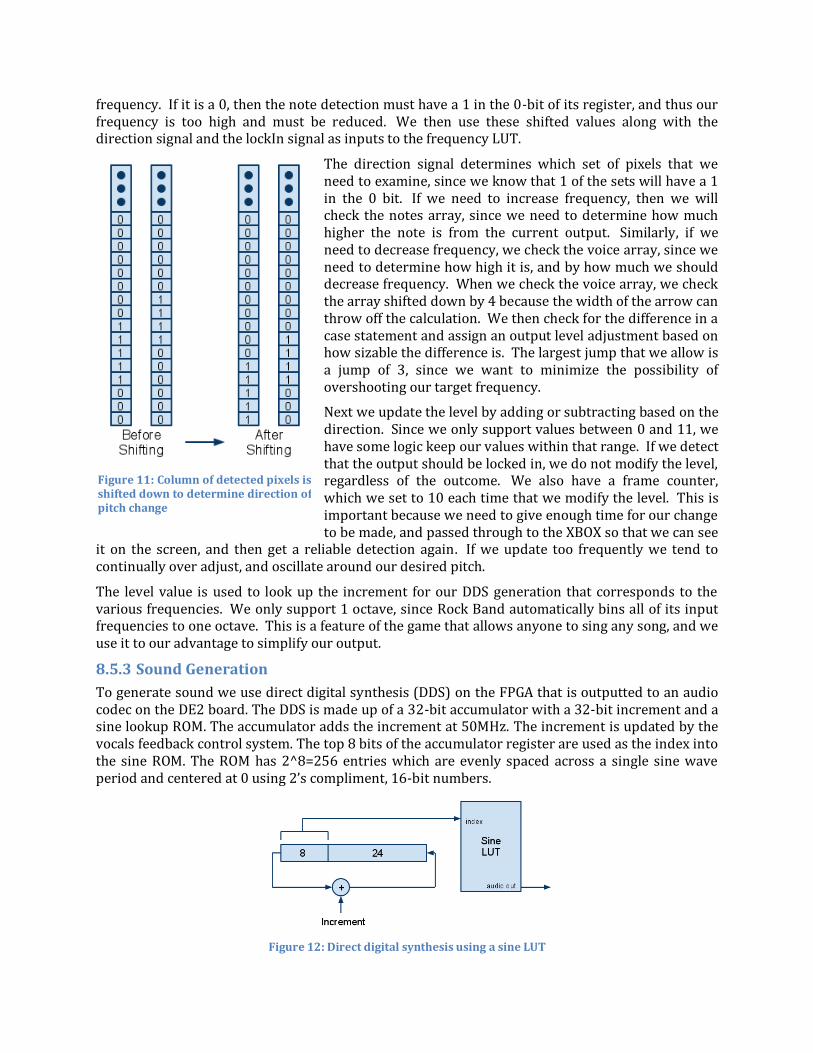
frequency. If it is a 0, then the note detection must have a 1 in the 0-bit of its register, and thus our frequency is too high and must be reduced. We then use these shifted values along with the direction signal and the lockIn signal as inputs to the frequency LUT.
The direction signal determines which set of pixels that we need to examine, since we know that 1 of the sets will have a 1 in the 0 bit. If we need to increase frequency, then we will check the notes array, since we need to determine how much higher the note is from the current output. Similarly, if we need to decrease frequency, we check the voice array, since we need to determine how high it is, and by how much we should decrease frequency. When we check the voice array, we check the array shifted down by 4 because the width of the arrow can throw off the calculation. We then check for the difference in a case statement and assign an output level adjustment based on how sizable the difference is. The largest jump that we allow is a jump of 3, since we want to minimize the possibility of overshooting our target frequency.
Next we update the level by adding or subtracting based on the direction. Since we only support values between 0 and 11, we have some logic keep our values within that range. If we detect that the output should be locked in, we do not modify the level, regardless of the outcome. We also have a frame counter, which we set to 10 each time that we modify the level. This is important because we need to give enough time for our change to be made, and passed through to the XBOX so that we can see
it on the screen, and then get a reliable detection again. If we update too frequently we tend to continually over adjust, and oscillate around our desired pitch.
The level value is used to look up the increment for our DDS generation that corresponds to the various frequencies. We only support 1 octave, since Rock Band automatically bins all of its input frequencies to one octave. This is a feature of the game that allows anyone to sing any song, and we use it to our advantage to simplify our output.
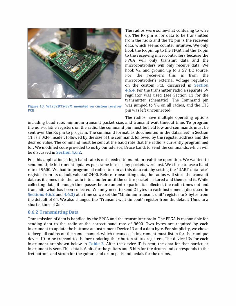
8.5.3 Sound Generation
To generate sound we use direct digital synthesis (DDS) on the FPGA that is outputted to an audio codec on the DE2 board. The DDS is made up of a 32-bit accumulator with a 32-bit increment and a sine lookup ROM. The accumulator adds the increment at 50MHz. The increment is updated by the vocals feedback control system. The top 8 bits of the accumulator register are used as the index into the sine ROM. The ROM has 2^8=256 entries which are evenly spaced across a single sine wave period and centered at 0 using 2’s compliment, 16-bit numbers.
Figure 12: Direct digital synthesis using a sine LUT
Figure 11: Column of detected pixels is shifted down to determine direction of pitch change

Our output is accurate to 0.01 Hz, which we can solve for by simply dividing the 50 MHz clock frequency by 2^32 for our 32-bit accumulator. With this we can accurately produce all of the 12 frequencies listed in Table 1. The 256 entry LUT has the data for one complete period of the sine wave, and how quickly we move through this table determines the frequency output. Therefore a higher frequency needs a higher increment and vice versa. A simple formula allows us to solve for the increment required for each frequency.
𝐼𝑛𝑐𝑟𝑒𝑚𝑒𝑛𝑡 = 𝐷𝑒𝑠𝑖𝑟𝑒𝑑 𝐹𝑟𝑒𝑞𝑢𝑒𝑛𝑐𝑦 ∗ 232
50 𝑀𝐻𝑧
The increment is added to an accumulator on every rising edge of the 50 MHz clock. The top 8-bits of this accumulate are the index to the LUT of sine values. The output of the sine table is then sent to the audio DAC for transmission on the speakers. The Audio DAC module used to drive the audio codec was provided to us by Terasic [5]. It runs on a 27MHz clock that we generate along with the video decoder clock in a PLL within the FPGA. We output the signal on both the left and right channels, so that we can use both stereo speakers to output the tone. Figure 12 illustrates how the DDS circuitry works.
Table 1: One octave of frequencies and their associated DDS increment values
Note Frequency (Hz) Increment Value A3 220 32’d18898 A3# 233.08 32’d20021 B3 246.94 32’d21212 C4 261.63 32’d22474 C4# 277.18 32’d23810 D4 293.66 32’d25255 D4# 311.13 32’d26726 E4 329.63 32’d28315 F4 349.23 32’d29999 F4# 369.99 32’d31782 G4 392 32’d33672 G4# 415.30 32’d35674
8.6 Wireless Communication
The FPGA communicates wirelessly with the drums, guitar, and bass via wireless radios. Each instrument has its own radio that receives commands from a single transmitter radio connected to the FPGA. The FPGA is responsible for sending data to the radio transmitter. The receiving radios are polled by microcontrollers to receive update commands. Each receiving radio and microcontroller is mounted on a custom printed circuit board (PCB), while the transmitting radio is mounted on a solder board connected to the FPGA.
8.6.1 Wireless Radios
The wireless radios chosen in this design are Radiotronix WI.232DTS low-power, long-range data transceivers [7]. They are each mounted on the WI.232DTS-EVM evaluation module, which contains a regulated voltage supply, antenna, and header pins for prototyping. The radios are a completely transparent UART to RF solution that act exactly like a direct UART connection. They are capable of multipoint-to-multipoint communication as well. The radios were donated to Cornell’s ECE department and given to us by our advisor, Bruce Land.
The radios were somewhat confusing to wire up. The Rx pin is for data to be transmitted from the radio and the Tx pin is the received data, which seems counter intuitive. We only hook the Rx pin up to the FPGA and the Tx pin to the receiving microcontrollers because the FPGA will only transmit data and the microcontrollers will only receive data. We hook Vdd and ground up to a 5V DC source. For the receivers this is from the microcontroller’s external voltage regulator on the custom PCB discussed in Section 4.6.4. For the transmitter radio a separate 5V regulator was used (see Section 11 for the transmitter schematic). The Command pin was jumped to Vdd on all radios, and the CTS pin was left unconnected.
The radios have multiple operating options including baud rate, minimum transmit packet size, and transmit wait timeout time. To program the non-volatile registers on the radio, the command pin must be held low and commands must be sent over the Rx pin to program. The command format, as documented in the datasheet in Section 11, is a 0xFF header, followed by the size of the command, followed by the register address and the desired value. The command must be sent at the baud rate that the radio is currently programmed for. We modified code provided to us by our advisor, Bruce Land, to send the commands, which will be discussed in Section 4.6.2.
For this application, a high baud rate is not needed to maintain real-time operation. We wanted to send multiple instrument updates per frame in case any packets were lost. We chose to use a baud rate of 9600. We had to program all radios to run at this data rate by setting the “UART data rate” register from its default value of 2400. Before transmitting data, the radios will store the transmit data as it comes into the radio into a buffer until the entire packet is stored and then send it. While collecting data, if enough time passes before an entire packet is collected, the radio times out and transmits what has been collected. We only need to send 2 bytes to each instrument (discussed in Sections 4.6.2 and 4.6.3) at a time so we set the “Minimum transmit unit” register to 2 bytes from the default of 64. We also changed the “Transmit wait timeout” register from the default 16ms to a shorter time of 2ms.
8.6.2 Transmitting Data
Transmission of data is handled by the FPGA and the transmitter radio. The FPGA is responsible for sending data to the radio at the correct baud rate of 9600. Two bytes are required by each instrument to update the buttons: an instrument Device ID and a data byte. For simplicity, we chose to keep all radios on the same channel, which means each instrument must listen for their unique device ID to be transmitted before updating their button status registers. The device IDs for each instrument are shown below in Table 2. After the device ID is sent, the data for that particular instrument is sent. This data is 6 bits for the guitars and 5 bits for the drums and corresponds to the fret buttons and strum for the guitars and drum pads and pedals for the drums.
Figure 13: WI.232DTS-EVM mounted on custom receiver PCB

Table 2: Instrument Device IDs
Instrument Device ID Guitar 0x40 Bass 0x80 Drums 0xC0
The data bits for each instrument are updated and sent to the transmitter module within the FPGA once a frame by each instruments button press modules. For most frames the values for each button will remain unchanged, but will be sent over the wireless regardless. The transmitter is oblivious to what data is changing and sends data to the instruments continuously. If the same data is sent, it is essentially the same as if a user were holding down the buttons with their fingers.
Figure 14: Block Diagram of the Wireless Module
The Wireless module decides what data to send to the radios and how quickly to send it. A separate module called SerialTransmitter handles sending out data bit by bit to the radio. Even though new instrument data is sent to the Wireless module only once a frame, the module transmits this data several times per frame to the instruments in case there are any packet losses. It sends the data continuously in a round-robin fashion, meaning it simply cycles through the instruments and sends them data as fast as possible. This is handled by a state machine that cycles between Guitar, Bass, and Drums. A status counter is updated each round to update which instrument to send data to. This counter is the select signal to a MUX that chooses which Device ID and data should be sent. The MUX will alternate between the Device ID and Data. The state machine also has states to handle idle time while the data is being sent 1 bit at a time by the transmitter. When it is time to send a new byte the state machine sends a StartSend signal to tell the transmitter to send the new data. In addition, the module also has a Baud clock generator that divides the clock appropriately to achieve a 9600 baud rate.
The SerialTransmitter module itself was provided to us by our advisor, Bruce Land, who had coded it up for a past project. Essentially it is a state machine that will cycle through each bit of a byte and send it to the radio at the baud clock rate given by the Wireless module. It requires a StartSend signal from the Wireless module to begin a new send.

The radio receives data from the SerialTransmitter via the FPGA’s GPIO ports. The radio is mounted on a solder board that sits next to the FPGA. On the board is a 5V regulator that converts the 9V supply from the wall to the needed 5V for the radio power supply. There are several other components associated with the regulator such as a capacitor to remove supply noise and a diode to prevent current from flowing the wrong way and destroying components. The FPGA only outputs 3.3V, which is below the 5V required input voltage needed by the radio. To solve this problem we used two PNP
transistors to level shift the FPGA output up to 5V. A photo of the
transmitter circuitry are shown in Figure 15.
8.6.3 Receiving Data
Each instrument has its own receiving radio hooked up to an ATmega644 microcontroller [6]. The radio receives all data transmitted by the FPGA for every instrument because all of the radios are on the same channel. The microcontroller is responsible for updating its data registers only when the appropriate Device ID has been received. The radio, microcontroller, and instrument controlling circuitry are mounted on the custom PCB discussed in Section 4.6.4.
The output from the radio is sent to the microcontroller’s UART Rx input pin (PIND.0). Each microcontroller is assigned a Device ID according to what instrument it is hooked up to, as found in Table 2. To receive data from the radios, we use the USART interrupt that enters an ISR when a new byte has been received. In order to do this, we enabled the Receiver Enable bit and RX Complete Interrupt Enable bits of the UCSR0B register, which set up the ISR. We also needed to make sure we were receiving the data at the correct baud rate of 9600, so we set the Baud rate prescalar assuming a 16MHz clock to be 103 by setting the UBRR0H and UBRR0L registers. We also use PORTC as an output to the optocouplers that press the buttons on the instruments. PIND is set to an input for the UART input.
The USART RX Complete ISR is entered when a new byte has been written to the UART receive register. When a byte is written to that register by the USART receiver a flag is set and when it is read the flag is reset. Upon entering the ISR, the byte is read into an rxByte register from the UDR0 receive register. First it checks to see if the received byte is a data byte or a Device ID byte by checking the top 2 bits (which are 0 only for data bytes). If it is a Device ID, then the ID is saved to the rxDeviceId byte. If it is a data byte, the current saved Device ID is checked against the unique ID saved in the microcontroller to determine if the data is intended for that instrument. If it is a match, PORTC is updated with the button data. PORTC drives the optocouplers that essentially “press” the buttons on the instruments.
8.6.4 Custom Circuit Board
A custom PCB was made to house the receiving radio, microcontroller, and 6 optocoupler chips for each instrument. The board was designed using ExpressPCB software and ordered through them online. We designed it on their standard two-layer board with silk screening according to their
Figure 15: Transmitter radio hooked up to the FPGA

design tips [8]. Our design started off with a board designed by Bruce Land and Nathan Chun for the ECE 4760 Microcontroller class. We were able to copy and edit that design, taking away unneeded pins to save space. We needed a lot of extra room for the large radio and 6-pin optocoupler chips. We also needed to add a 2 PNP level shifter circuit to convert the 3.3V output of the radios to 5V for the microcontroller to read. Pictures of the layout design and unpopulated board are shown in Figure 16.
Figure 16: Custom receiver PCB layout (left) and the unpopulated board (right)
8.7 Controller Modification
In order to communicate with the Xbox 360, we needed to modify the guitars and drums to allow us to simulate button presses. We were unable to communicate with the Xbox directly because they use a proprietary wireless protocol to communicate with the instruments that we did not have access to. We also wanted to modify the instruments while maintaining their original functionality so that the instruments could be used after modification when the device was not active. With these restrictions in mind, we decided to use optocouplers wired across the buttons in each of the instruments to simulate button presses with electronic signals from the microcontrollers on the receiver board.
Figure 17: Parallel tapping of wires leading from guitar buttons to the main circuit board

We chose the H11F1 optocoupler because it acts exactly like a resistor and can simulate a button press. When receiving a low signal, the optocoupler has a very high resistance, which models an open circuit just as if a button were not being pressed. When a high signal is sent to the optocoupler, it has a very low resistance, which closely models a closed circuit through the button when it is pressed and connects the two switch leads. We wire the optocoupler in parallel with the existing physical button so that either can be used to close the switch. When the device is in use the physical buttons are not used and vice versa when a user wants to play the instrument themselves. This allows us to maintain the existing functionality while also granting the FPGA control over the instruments when the device is in use. The modification schematic is in Section 15.1.
Parallel wiring requires tapping into both leads of the button switch on the instrument without disconnecting the original button. For the guitars, we simply had to intercept wires connecting the button switches to the main circuit board and tap our own wires off of them. We created a small solder board to serve as an intermediate stop for the switch wires on their way to the main board. We tap wires onto this solder board that lead to the optocouplers.
Figure 18: Tapping directly into switch lead vias on the drums
For the Drums the modification is a little more complicated. We attempted to intercept the wires from the drum pads themselves but found that they were sending short pulses to the main board to indicate acceleration on the drum pads. Instead, we chose to tap directly into the circuit board of the drums where the button leads are. We probed with a multi-meter to find the correct places on the board and luckily there were small via holes for all the button leads that we could solder to. We had to use very small diameter wire to fit into the vias and attached header pins to the wires to connect to the optocouplers. For all modifications, gaining access to the internals of the instruments was as simple as unscrewing several screws. However, this did void the warranty on the controllers.
9. Design Process
In this section we will document the design process of the device. Major milestones and challenges will be discussed along with our solutions and design decisions. The cursor module we designed for testing and debugging is discussed in detail in Section 9.2.

9.1 Designing and Implementation Timeline
Our project was done over the course of an entire year. In the first semester we planned out the entirety of the project, trying to plan for any major difficulties that we would encounter. We knew that we would need to be able to determine color information of specific pixels, so the first thing that we did was design the cursor module described above. We broke the design process up into various smaller milestones, so that we could divide up the work efficiently. Our goal for the first semester was to get single player guitar working with blinking LEDs, no interface with the guitar. This was to prove the concept of our detection scheme. Eliminating the guitar interface from this goal was mainly so that we could figure out the detection alone, and not worry if there was some hardware interface issue causing any problems that would arise.
With all of our modules, we tried to make them relate to how humans play the game, as much as we possibly could. For example, with the guitar module, a human plays with one hand on the fret buttons, and one hand strumming. Thus we created the FretPresser and Strummer modules to simulate this interaction. Splitting up the work into smaller modules was our plan from the beginning, because it often makes debugging easier. We also made it a point to descriptively name all of our signals between modules (and within modules). This made it much easier to keep track of all of the signals, and what their function was. When designing the single player module, we started with the pixel detector, and then worked up the hierarchy. Once we had a design for the detection we could output raw detection data to the LEDs, to be sure that we were getting detections before we moved on. Once we were sure that the detection was at least detecting (not necessarily correctly) we moved on to designing the two output modules. The FretPresser and Strummer came together pretty much as we expected that they would.
Once we had all the pieces in place, we could go through and ensure the detection was working as we thought. This was not an easy task, as matching blinking LEDs to fast moving notes on the screen is not the easiest thing to do. Since our detection grids were directly inside where the notes get hit on the screen, the timing of the LEDs was fairly in sync with what we were seeing on the screen. We debugged our detection and the thresholds using the LEDs until it appeared to be fairly accurate. This was our goal for the first semester, and we met it. A block diagram of the progress to this point can be seen in Figure 19. We would be able to truly test the accuracy once we connected our circuit to the guitar.
Figure 19: Block diagram of the design implemented after the first semester

Once we connected the circuit up to an actual guitar, everything changed. We started with a wired interface, so that we could test our circuitry without the added wireless component. We ran into a bunch of different problems during this phase of the design. First of all, we realized that we couldn’t do the detection at the bottom of the screen because there are special effects when the notes are hit. When you successfully hit a note, the note explodes and shoots out some extra color, and there are also some grey ripples that scatter on the screen. These effects cause false detection problems very regularly. Because of this, we had to move the detection grids about halfway up the screen, and add in the buffer to schedule the notes with a delay factor. Next we debugged the problem with the held notes by adding in the wingman as was described previously. After the wingman addition and some minor threshold tweaking, we were able to get the single player guitar to hit 100% of the notes on expert difficulty.
The next problem that we decided to tackle was the vocals. We had previous experience with Direct Digital Synthesis from our coursework, so designing that part of the system was straightforward. Designing the detection and thresholds was a little easier this time around, because we had a little more experience with the colors of the screen. We had to keep expanding the height of the detection strip, since we noticed that the arrow can go higher than we originally expected. When the arrow is at the top of the allowed range, and is higher than the nearby note, the arrow is angled such that the piece we were detecting is up higher than the height of the black area. This was unexpected, but easy enough to adjust for. The other main problem that we ran into was oscillations, which we solved by adding the “lock in” signal, and forcing the system to wait 10 frames in between adjustments. This got our vocal circuitry to a level that we were satisfied with, and we put it aside to eventually come back and attempt to tweak if we had extra time at the end of the year.
The next big step was getting the wireless communication to work, and designing and populating our custom PCBs. The design of the custom PCB involved modifying an existing design for the micro-controller from ECE4760. We added in our circuitry for the wireless radio and the interface to the instrument within the specifications of the standard size board from ExpressPCB. We tested the wireless circuit originally using the FPGA to transmit, and an STK500 to receive the signal. We had 8 switches on the FPGA correspond to the 8 LEDs on the STK500, and tested that we could transmit the status of the switches and display their state on the LEDs. It took us some time to get the radios configured the way we wanted them, since we had to program specific registers. Once we identified all of the registers that we needed to change it was not difficult to set them to the correct values. Once we had this working, we knew that we had the wireless radios working as expected, and we could populate our PCB. We populated the PCBs, which we found out had some minor space miscalculations, which we were able to deal with by grinding down our opto-couplers slightly, and using a 2-pin wide connector on the radio instead of a 1-pin wide connector.
Once we had the wireless up and running, we could start working with multiple instruments at a time. We now began to expand to 4 player mode, and set the system to “no fail mode” so that we could play through songs even if all of the instruments we not attached to the system. We first aligned the detection for the guitar and bass, and got 2 guitars playing. Then we got the vocals working, which was simply moving the detection from the bottom of the screen to the top of the screen. Then we got the drum system set up, which involved porting over and adjusting the guitar code, as previously described. Once we got all of the instruments running, we tried to optimize the detections to get the instruments to 100%. Unfortunately, because the area that we had to work with was now decreased significantly, there was lower pixel resolution per instrument, which made accurate detection more difficult. Using the wingman to solve the held note problem was easy when we had the whole screen for 1 instrument, but now with 3 instruments across the screen, everything is much more cramped. This made it impossible, in the amount of time we had, to get

the guitars back up to 100%. We were able to get all three instruments to get 97% and higher in our tests on the final day.
Overall, we progressed through our design by starting with 1 instrument’s detection with no interface, simply blinking LEDs. Then we added in a wired interface to the instrument. Then we got the wireless interface working, before expanding to all four instruments on one screen. We implemented and executed our design in this way to help minimize difficulty with debugging and testing. We have learned from our classes that things inevitably always go wrong in a complex design. Our key throughout this whole process was design for test, and that mindset is likely what helped us produce the results that we did, with a significant amount of the work being done over just one semester. We used a Cursor Module throughout the entire design for testing, which is described in Section 9.2 below.
9.2 Cursor Module
Before providing pixel locations and color thresholds to our note detection modules, we first needed to determine what pixels on the screen should be monitored and what colors to look out for to determine a note trigger. To make this process easier, we decided to make a simple module that could tell us the location and RGB value of any pixel on the screen. The module moves a single white pixel cursor around the screen and can display the 10 bit color value of red, green or blue on the red LEDs on the DE2 board. The movement of the cursor is controlled by the switches and a button on the board. The LEDs can display red, green or blue values based on switch settings as well. There is also a button to move the cursor by a factor of 10 in any direction and a button to reset the cursor to the middle of the screen. Finally, the location of the cursor is displayed on the 7-Segment displays.
The cursor module includes simple logic to display the cursor on the screen, move the cursor, display the cursor location, and display the appropriate color values to the LEDs. The module intercepts the SDRAM pixel color output to VGA along with the VGA controller’s requested pixel coordinates and blanking information. Inputs from the switches and buttons are used within the module for controlling the cursor. A pixel location is outputted to an external 7-segment display driver along with the 10 bit color value for the LEDs.
The cursor is displayed to the screen by implementing a MUX that selects between the SDRAM output and a white color value. The MUX selects the white color value when the VGA controller requests pixel data from the SDRAM at the cursor’s current location. Otherwise, the SDRAM data passes through the MUX as normal.
The position of the cursor is updated whenever the user presses KEY[3]. There is also a debouncing module discussed below that makes sure a held button pressed is only evaluated as a single update. When the update key is pressed, the cursor location registers are updated by incrementing or decrementing a pixel according to the direction specified by the user using SW[3:0]. The switch assignments are shown in Table 3 below. Additionally, the user has the option of moving the cursor by 10 pixels per button press by enabling SW[4]. This makes traversing the screen much faster. There is no check to make sure the user is not incrementing beyond the limits of the raster. The value of the cursor location registers is outputted to external 7-segment display drivers provided to us by Professor Land. Optionally, the user can move in both an X and Y direction at the same time. The position of the cursor can be reset to the center of the screen at any time by pressing KEY[0].
Finally, the red, green and blue values from the SRAM are read into the module and can be displayed to 10 of the red LEDs. Due to the small number of LEDs, we are only able to display one color channel’s value at a time. This value is MUXed using the switches as a select signal to choose between them. When SW[17] is off, no RGB values are displayed. When SW[17] is on, SW[16]
displays the red value, SW[15] the green, and SW[14] the blue. The LEDs are only updated when the location of the cursor is requested by the VGA controller so only 1 pixel’s color value is read. The value is held while the other pictures in the frame are read by the controller.
Table 3: Cursor module interface components and functionalities
Hardware Component Description of Use
LED_RED[9:0] Displays 10 bit color value for R, G or B SW[17] Enables Cursor Module SW[16] Select to display Red SW[15] Select to display Green SW[14] Select to display Blue SW[4] Move 10 pixels enable switch SW[3] Select to move up SW[2] Select to move down SW[1] Select to move left SW[0] Select to move right KEY[3] Move and update cursor KEY[0] Reset to the middle of screen
We eventually realized it would be helpful to display the location of all of our pixel detectors on the screen constantly while playing the song so we could visually inspect whether or not they were positioned properly. To implement this we added a pixel location check for each of the pixels we wanted displayed. When the correct location was being read from the raster in SDRAM, we change its color value to white, just as we had done with the single cursor pixel. We eventually instantiated this once for each pixel detector on the screen.
10. Results
The FPGA Rock Band Player is able to play Rock Band 2 with up to four instruments at a time on expert difficulty level. The wireless communication was successfully implemented and allows users to place the instruments far away from the FPGA without needing to hook up any additional wires. The controllers were modified successfully without destroying any of the original functionality. The device is capable of beating nearly any song on expert with very accurate performance from the guitars and bass, with an average accuracy of 98% for all three. The vocals are also strong but consistently lower in accuracy with an average of 77%. Additional statistics are listed in Table 4 below. It should be noted that the minimum score for the guitars and drums is 96%, which is impressive. The accuracies are easy to verify because Rock Band 2 displays them for us after each song; all we had to do was play through entire songs to get our data.
We are able to beat nearly any song on expert, but the final scores are not as competitive as we had hoped. We had hoped to achieve competitively high scores with a 5 star rating. The device can consistently get 3.5 stars on any expert song. However, this is largely due to the fact that we did not implement a way for the instruments to use star power, which would give them a significant score multiplier. The drums and guitars often hit several hundred notes in a row, which would greatly benefit from the star power multiplier. In addition, the screen flashes associated with hitting star power notes often breaks the note streak and resets the multiplier to 1x. This occurs quite often and greatly reduces the total score.
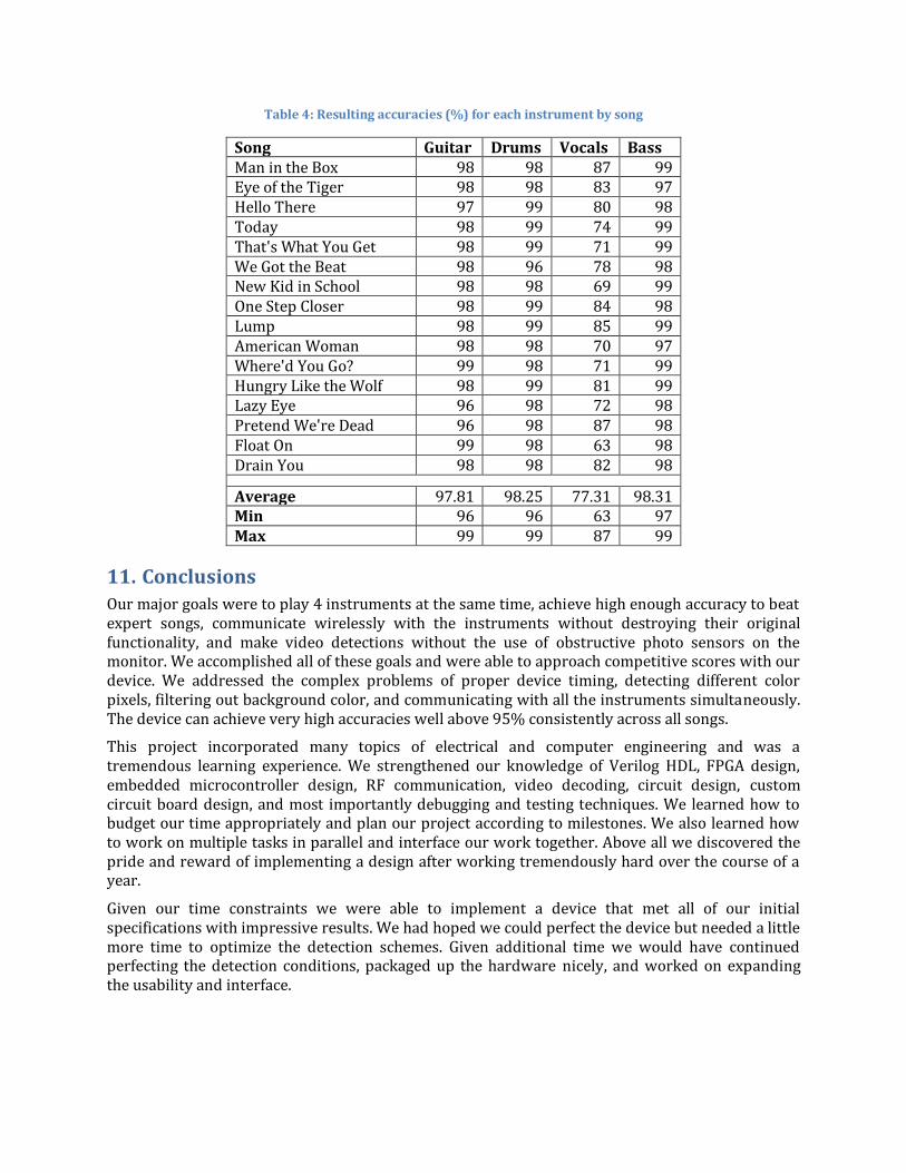
Table 4: Resulting accuracies (%) for each instrument by song
Song Guitar Drums Vocals Bass Man in the Box 98 98 87 99 Eye of the Tiger 98 98 83 97 Hello There 97 99 80 98 Today 98 99 74 99 That's What You Get 98 99 71 99 We Got the Beat 98 96 78 98 New Kid in School 98 98 69 99 One Step Closer 98 99 84 98 Lump 98 99 85 99 American Woman 98 98 70 97 Where'd You Go? 99 98 71 99 Hungry Like the Wolf 98 99 81 99 Lazy Eye 96 98 72 98 Pretend We're Dead 96 98 87 98 Float On 99 98 63 98 Drain You 98 98 82 98 Average 97.81 98.25 77.31 98.31 Min 96 96 63 97 Max 99 99 87 99
11. Conclusions
Our major goals were to play 4 instruments at the same time, achieve high enough accuracy to beat expert songs, communicate wirelessly with the instruments without destroying their original functionality, and make video detections without the use of obstructive photo sensors on the monitor. We accomplished all of these goals and were able to approach competitive scores with our device. We addressed the complex problems of proper device timing, detecting different color pixels, filtering out background color, and communicating with all the instruments simultaneously. The device can achieve very high accuracies well above 95% consistently across all songs.
This project incorporated many topics of electrical and computer engineering and was a tremendous learning experience. We strengthened our knowledge of Verilog HDL, FPGA design, embedded microcontroller design, RF communication, video decoding, circuit design, custom circuit board design, and most importantly debugging and testing techniques. We learned how to budget our time appropriately and plan our project according to milestones. We also learned how to work on multiple tasks in parallel and interface our work together. Above all we discovered the pride and reward of implementing a design after working tremendously hard over the course of a year.
Given our time constraints we were able to implement a device that met all of our initial specifications with impressive results. We had hoped we could perfect the device but needed a little more time to optimize the detection schemes. Given additional time we would have continued perfecting the detection conditions, packaged up the hardware nicely, and worked on expanding the usability and interface.

12. Future Work
There are several ways this design can be improved including perfected detection, device packaging and usability and interface. Currently there are several events in the game that cause us to miss notes or false trigger and break the hit streak. Once a series of star power notes are hit in a row they cause a flash on the screen that can cause false triggering. We would like to work on detecting the flashes and adjusting the thresholds accordingly during this time. We would like a way for the instruments to automatically activate star power. When star power is activated, the background changes significantly which makes it hard to detect notes. We would like to add additional threshold conditions that would be used only when the background has changed. We could tighten our current note detection to be less dependent on the background colors. Finally, we would like to perfect the balance between being able to hit held notes and hammer-on notes.
The packaging of our hardware can also be improved. We currently have the wireless receiving boards externally connected to the drums and guitars by wires. We would like to create a small enough board to fit inside the controllers by using surface mount microcontrollers and smaller radios. This way the receivers would not be in risk of getting disconnected or broken and would not be visible to the user. We could also design a board for the FPGA that includes the necessary external chips on the DE2 board without the large area overhead of unneeded components. We would take this board and place it in a small box that could be placed near the Xbox 360 out of site.
Finally, we would like to improve the interface to allow users to easily select different modes. We would want options to select different instruments to play and have the device turn on all the appropriate controllers and log each into the game without the user having to turn on each instrument individually. This would make for a much easier experience for the user without large setup times.
13. Special Thanks
We would like to thank the following people and vendors without whom we could not have made this project a success.
Radiotronix for donating the wireless radios to the ECE department at Cornell Atmel for donating the Mega644 microcontrollers to the ECE department at Cornell Terasic and Altera for sample code used with the DE2 development board The Electrical and Computer Engineering department at Cornell for giving us space to work,
access to lab equipment, and for dozens of circuit components we used in our project Bruce Land for guiding and supporting us throughout every stage of this project
14. References
[1] Jeff Yates and Li Yau. Automated Rock Band Player. 2010. http://people.ece.cornell.edu/land/courses/ece4760/FinalProjects/s2010/jay29_ly56/jay29_ly56/index.html
[2] Gautum Kamath and Dominick Grochowina. Rock Band Vocal Bot. 2011. http://people.ece.cornell.edu/land/courses/ece4760/FinalProjects/s2011/dsg88_gck43/dsg88_gck43/index.html
[3] http://hacknmod.com/hack/automate-rock-band-to-never-miss-a-beat/
[4] Wikipedia’s NTSC page. http://en.wikipedia.org/wiki/NTSC
[5] Terasic’s DE2 Board Resources Page. http://www.terasic.com.tw/cgi-bin/page/archive.pl?Language=English&CategoryNo=53&No=30&PartNo=4

[6] Atmel’s ATmega644 Resources Page. http://www.atmel.com/dyn/products/product_docs.asp?category_id=163&family_id=607&subfamily_id=760&part_id=3694
[7] Radiotronix’s Wi.232DTS Resource Page. http://www.radiotronix.com/products/proddb.asp?ProdID=179#docs
[8] ExpressPCB’s PCB Design Tips Page. http://www.expresspcb.com/ExpressPCBHtm/Tips.htm
15. Schematics
Below are schematics of the circuitry designed for this project.
15.1 Transmitter Radio

15.2 Receiver Board
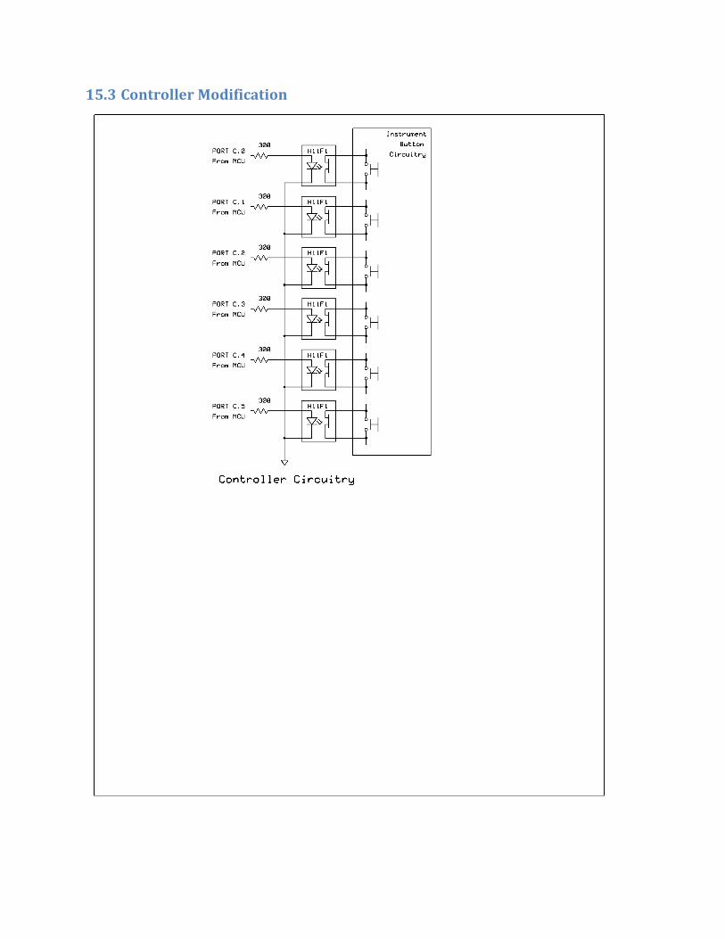
15.3 Controller Modification
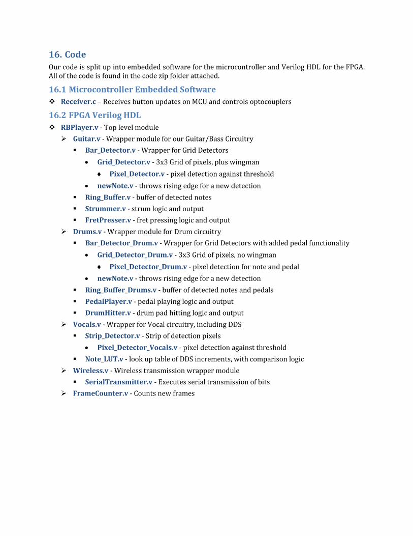
16. Code
Our code is split up into embedded software for the microcontroller and Verilog HDL for the FPGA. All of the code is found in the code zip folder attached.
16.1 Microcontroller Embedded Software
Receiver.c – Receives button updates on MCU and controls optocouplers
16.2 FPGA Verilog HDL
RBPlayer.v - Top level module
Guitar.v - Wrapper module for our Guitar/Bass Circuitry
Bar_Detector.v - Wrapper for Grid Detectors
Grid_Detector.v - 3x3 Grid of pixels, plus wingman
Pixel_Detector.v - pixel detection against threshold
newNote.v - throws rising edge for a new detection
Ring_Buffer.v - buffer of detected notes
Strummer.v - strum logic and output
FretPresser.v - fret pressing logic and output
Drums.v - Wrapper module for Drum circuitry
Bar_Detector_Drum.v - Wrapper for Grid Detectors with added pedal functionality
Grid_Detector_Drum.v - 3x3 Grid of pixels, no wingman
Pixel_Detector_Drum.v - pixel detection for note and pedal
newNote.v - throws rising edge for a new detection
Ring_Buffer_Drums.v - buffer of detected notes and pedals
PedalPlayer.v - pedal playing logic and output
DrumHitter.v - drum pad hitting logic and output
Vocals.v - Wrapper for Vocal circuitry, including DDS
Strip_Detector.v - Strip of detection pixels
Pixel_Detector_Vocals.v - pixel detection against threshold
Note_LUT.v - look up table of DDS increments, with comparison logic
Wireless.v - Wireless transmission wrapper module
SerialTransmitter.v - Executes serial transmission of bits
FrameCounter.v - Counts new frames