fpml russian regulatory reporting working group fpml russian
TRANSCRIPT
1
SEISMIC CAPACITY OF BUILDINGS MADE WITH REINFORCED CONCRETE PANELS CAST WITH WOOD BLOCKS SYSTEM.
Fabrizio COMODINI1, Alessandro FULCO2 and Marco MEZZI3
ABSTRACT
This paper presents the main results of a nonlinear analysis used for the seismic design of a building constructed with LLRCW - WBS panels (Large Lightly Reinforced Concrete Walls - Wood Blocks System). The building system has been characterized from the structural point of view via experimental tests that demonstrate suitable behavior in the constituent elements regarding vertical, horizontal and cyclic loads . The results obtained from experimental tests have been used to define the calculation models with the complete characterization of the seismic capacity of the LLRCW–WBS building system. The results of the numerical analyses in terms of the mechanical behavior of the panels, of their stress-strain states and of their global and local elastic-plastic behavior are then described.
INTRODUCTION
The structural system of reinforced concrete buildings traditionally consists of frames made out of beams and columns. Less attention has been reserved towards structures entirely built with r.c. shear walls, typically used in buildings of modest proportions. Unlike frame structures, this structural typology requires a much greater quantity of concrete in accordance to the vertical loads to be borne. Furthermore, the walls, which are generally joined to each other, constitute a box system of limited slenderness. This allows for elevated shear resistance in the r.c. wall plane that in turn allows for a reduction in the longitudinal reinforcement of the section (Paulay and Park 1975). Following this, the new building technology of large lightly-reinforced walls (LLRCW) was introduced. The use of these systems has recently become more widespread, often together with framed systems (Mezzi and Comodini, 2010). Examples of buildings built with such methods can be found in various countries (Moroni 2002). A famous example is the Hospital of Santa Monica in California which was damaged by the 1994 Northridge earthquake. The behavior of its walls was carefully examined (Orackal et al 2009) and from the analysis of these structures it emerged that their resistance to seismic forces depended on the relationship between the area of the walls and the surface of the floor. Systems of LLRCW can now be found in new building typologies brought about with the aim of uniting structural necessities with the technological needs of thermal-acoustic insulation. A particular structural system of reinforced concrete walls classified as LLRCW is that made by using technologies based on System Wood Blocks (WBS). In this case a light material, such as wood, constitutes a formwork for the reinforced concrete structure (EOTA 2002). This structural system is the subject of this paper. In recent years these kind of structures have been the subject of a huge amount of
1 Assistant Professor, University eCampus, Como, Italy, [email protected] 2 Ph.D. Student, University of Perugia, Perugia, Italy, [email protected] 3 Associate Professor, University of Perugia, Perugia, Italy, [email protected]
2
experimental analyses (Ceccoli et al. 2008; Comodini et al. 2013) and theoretical studies (Scotta 2010; Comodini et al. 2013). In large lightly reinforced concrete walls systems, the evaluation of the seismic response is of particular importance. It should be evaluated taking into account mainly the local response of the elements forming the building. The characterization of the elastic-plastic behavior of LLRCW-WBS panels, leads to the definition of global models able to reproduce the global behavior of the structures concerning the flexural rigidity and the shear stiffness of the elements that compose the generic structure. In recent years this kind of structures have been the subject of many experimental analyses (Trombetti et al. 2008) and showed a local ductility and an energy dissipation significantly greater than indicated in the norms (NTC 2008, EC8 2004) and in the guidelines (Linee guida CSLP 2011). The guidelines, in accordance with the Italian and European norms, set, for LLRCW-WBS systems, a structure factor q0 ≤ 2 or, in case of adequate numerical analyses supported by experimental results, less than or at least equal to 3. Furthermore the guidelines, in accordance with the norms, consider this kind of structures belonging to a low ductility class CD”B”, since the collapse mechanisms are mainly due to shear or flexural-shear mechanisms (Lineeguida CSLP 2011). In literature there are several theoretical-numerical approaches (Scotta 2010, Ceccoli et al. 2008) that can be used to evaluate the resistance of LLRCW-WBS panels under seismic actions. This paper shows the results of experimental tests conducted on LLRW-WBS panels. The building system must be characterized from the structural point of view via experimental tests that demonstrate suitable behavior in the constituent elements regarding vertical, horizontal and cyclic loads (Linee guida CSLP 2011). The guidelines (Linee guida CSLP 2011) set out four different types of tests as listed in Table 1. The results obtained from type 1 experimental tests can be used to define the calculation models for this structural typology. After all the tests required by the guidelines (Table 1) have been executed it will be possible to describe the complete characterization of the seismic capacity of the LLRCW-WBS building system. Data from experimental tests have been used to define the elastic-plastic models at the base of the local and global seismic behavior of building made with LLRCW-WBS. In this article two different methods for modeling the construction type are proposed. With reference to a case study, linear and non linear analyses have been conducted in order to study the seismic capacity of the structure in terms of ductility and global resistance. The examination of the results coming from the global analysis allows to evaluate the global structure factor q that has to be used in the linear analyses as a function of the local capacity of the panels that has been determined via experimental tests.
THE BUILDING TECNIQUE
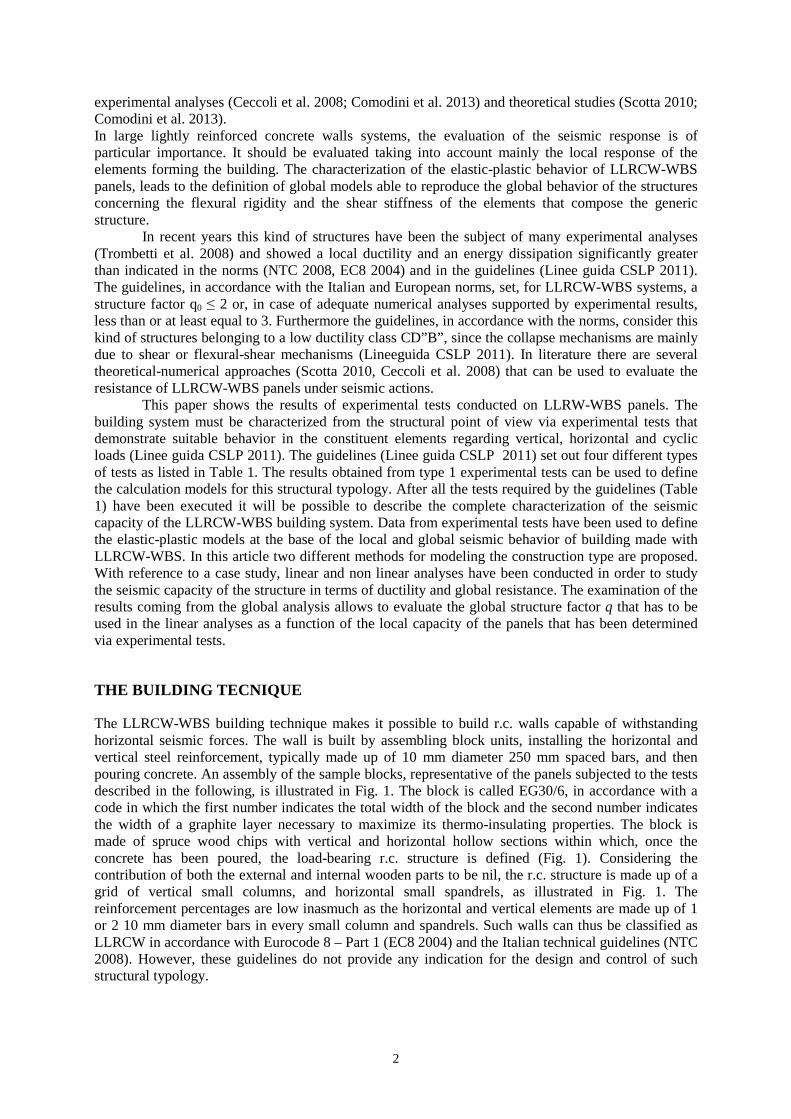
The LLRCW-WBS building technique makes it possible to build r.c. walls capable of withstanding horizontal seismic forces. The wall is built by assembling block units, installing the horizontal and vertical steel reinforcement, typically made up of 10 mm diameter 250 mm spaced bars, and then pouring concrete. An assembly of the sample blocks, representative of the panels subjected to the tests described in the following, is illustrated in Fig. 1. The block is called EG30/6, in accordance with a code in which the first number indicates the total width of the block and the second number indicates the width of a graphite layer necessary to maximize its thermo-insulating properties. The block is made of spruce wood chips with vertical and horizontal hollow sections within which, once the concrete has been poured, the load-bearing r.c. structure is defined (Fig. 1). Considering the contribution of both the external and internal wooden parts to be nil, the r.c. structure is made up of a grid of vertical small columns, and horizontal small spandrels, as illustrated in Fig. 1. The reinforcement percentages are low inasmuch as the horizontal and vertical elements are made up of 1 or 2 10 mm diameter bars in every small column and spandrels. Such walls can thus be classified as LLRCW in accordance with Eurocode 8 – Part 1 (EC8 2004) and the Italian technical guidelines (NTC 2008). However, these guidelines do not provide any indication for the design and control of such structural typology.
3
Fig. 1 Example of assembly of EG30/6 blocks: horizontal and vertical sections
EXPERIMENTAL TESTS To evaluate the strength and mechanical behavior of LLRCW-WBS panels a campaign of experimental tests was carried out. These included tests on centered axial compression and diagonal compression. In accordance with the relevant Italian guidelines (Linee guida CSLP 2011) the tests are aimed at both calculating the modulus of elasticity Eel and shear modulus Gel, and observing the collapse modes. The tests are carried out on square panels with a lateral width of 1000 mm. Horizontal cyclic pseudo-static tests have been carried out on real scale panels named SP1 and SP2 in order to determine their seismic capacity. Panels SP1 and SP2 have dimensions W x H (Width, Height) equal to 3,00 x 3,00 and 4,00 x 3,00 respectively. The total thickness of the panel, including the wooden formwork, is 300 mm, and the effective r.c. thickness teq is 160 mm. The panels are made by assembling EG30/6 wood blocks and are characterized by small 180 × 160 mm columns and small 140 × 100 mm (width × height) spandrels. The effective section of the panel is given only by the contribution of the small concrete columns. Therefore the total area A of the panel is A = 4 · Acol = 115800 mm2, where Acol is the area of a single small column. The thickness of the equivalent full wall with an area equivalent to the area of its small columns is teq = 115,20 mm. The reinforcement is inserted vertically and horizontally into the small columns and spandrels and consists of one 10 mm diameter bar for each small column and spandrel for the panels to be tested under axial compression and horizontal cyclic load, and of two 10 mm diameter bars for each small column and spandrel for the panels to be tested under diagonal compression. The panels are made of class C25/30 concrete and B450C steel (NTC 2008) characterized by a yielding strength of 450 N/mm2. Table 1 Experimental tests provided for the characterization of the building system (Linee guida CSLP, 2011)
Test type
Prototypes Loads Measured parameters
1 Panels (1x1) Axial compression Diagonal
Compression Elastic modulus
2 Panels (h(interstory)×b) b ≥ 1 m
Centred axial compression Buckling collapse load
3
Panels (h(interstory)×b) b ≥ 3 m
with/without openings
Constant axial compression + horizontal load in the plane of
the panel
Strength Displacement capacity
Energy dissipation
4 L and T
connections
Constant axial compression and moment applied to the
connection Joint efficiency
4
RESULTS OF THE TESTS
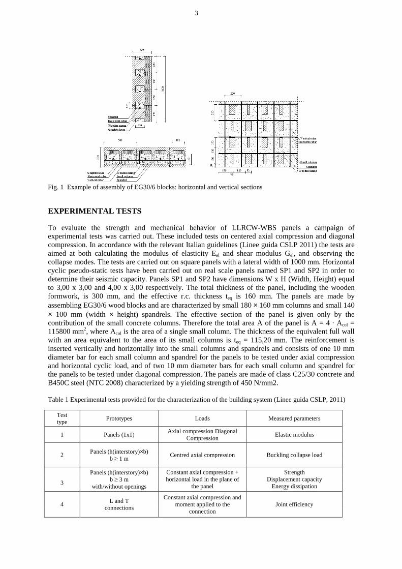
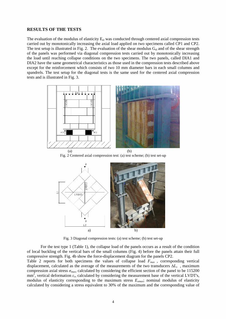
The evaluation of the modulus of elasticity Eel was conducted through centered axial compression tests carried out by monotonically increasing the axial load applied on two specimens called CP1 and CP2. The test setup is illustrated in Fig. 2. The evaluation of the shear modulus Gel and of the shear strength of the panels was performed via diagonal compression tests carried out by monotonically increasing the load until reaching collapse conditions on the two specimens. The two panels, called DIA1 and DIA2 have the same geometrical characteristics as those used in the compression tests described above except for the reinforcement which consists of two 10 mm diameter bars in each small columns and spandrels. The test setup for the diagonal tests is the same used for the centered axial compression tests and is illustrated in Fig. 3.
(a) (b)
Fig. 2 Centered axial compression test: (a) test scheme; (b) test set-up
a) b)
Fig. 3 Diagonal compression tests: (a) test scheme; (b) test set-up
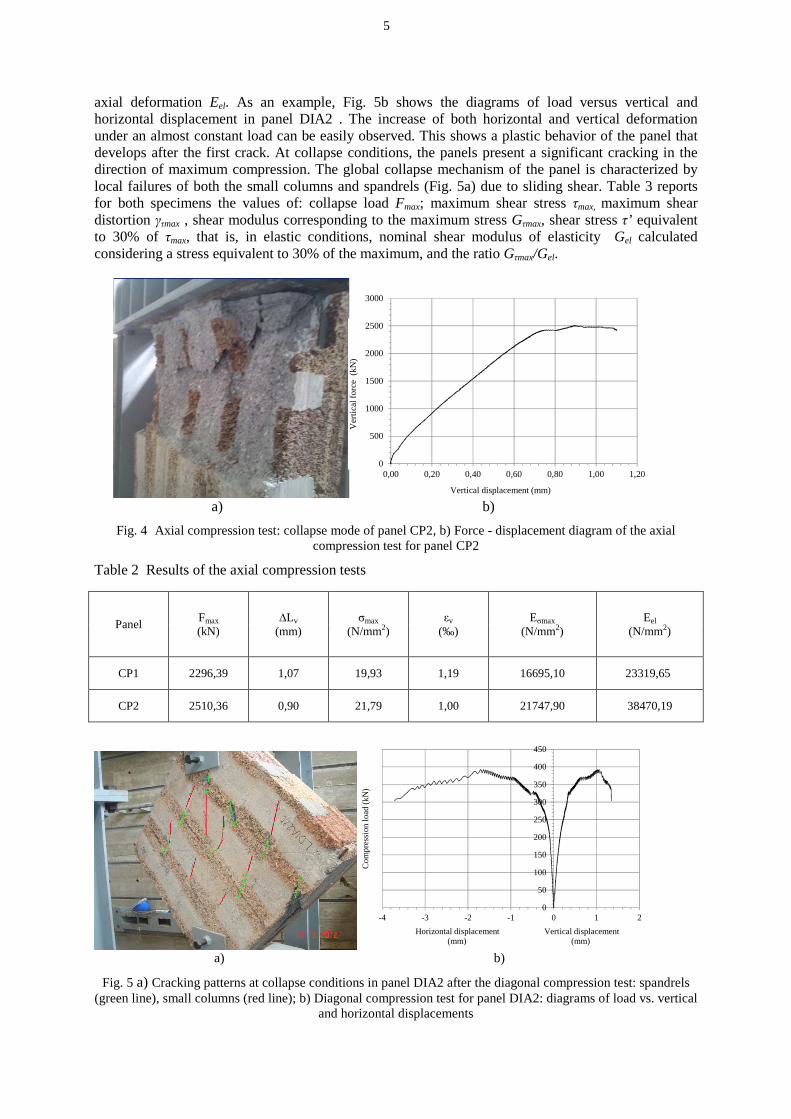
For the test type 1 (Table 1), the collapse load of the panels occurs as a result of the condition of local buckling of the vertical bars of the small columns (Fig. 4) before the panels attain their full compressive strength. Fig. 4b show the force-displacement diagram for the panels CP2. Table 2 reports for both specimens the values of collapse load Fmax , corresponding vertical displacement, calculated as the average of the measurements of the two transducers ∆Lv , maximum compression axial stress σmax, calculated by considering the efficient section of the panel to be 115200 mm2, vertical deformation εv, calculated by considering the measurement base of the vertical LVDT's, modulus of elasticity corresponding to the maximum stress Eσmax; nominal modulus of elasticity calculated by considering a stress equivalent to 30% of the maximum and the corresponding value of
5
axial deformation Eel. As an example, Fig. 5b shows the diagrams of load versus vertical and horizontal displacement in panel DIA2 . The increase of both horizontal and vertical deformation under an almost constant load can be easily observed. This shows a plastic behavior of the panel that develops after the first crack. At collapse conditions, the panels present a significant cracking in the direction of maximum compression. The global collapse mechanism of the panel is characterized by local failures of both the small columns and spandrels (Fig. 5a) due to sliding shear. Table 3 reports for both specimens the values of: collapse load Fmax; maximum shear stress τmax, maximum shear distortion γτmax , shear modulus corresponding to the maximum stress Gτmax, shear stress τ’ equivalent to 30% of τmax, that is, in elastic conditions, nominal shear modulus of elasticity Gel calculated considering a stress equivalent to 30% of the maximum, and the ratio Gτmax/Gel.
0
500
1000
1500
2000
2500
3000
0,00 0,20 0,40 0,60 0,80 1,00 1,20
Vertical displacement (mm)
Ver
tical
forc
e (k
N)
a) b)
Fig. 4 Axial compression test: collapse mode of panel CP2, b) Force - displacement diagram of the axial compression test for panel CP2
Table 2 Results of the axial compression tests
Panel Fmax (kN)
∆Lv (mm)
σmax (N/mm2)
εv
(‰) Eσmax
(N/mm2) Eel
(N/mm2)
CP1 2296,39 1,07 19,93 1,19 16695,10 23319,65
CP2 2510,36 0,90 21,79 1,00 21747,90 38470,19
0
50
100
150
200
250
300
350
400
450
-4 -3 -2 -1 0 1 2
Horizontal displacement Vertical displacement(mm) (mm)
Co
mp
ress
ion
loa
d (
kN)
a) b)
Fig. 5 a) Cracking patterns at collapse conditions in panel DIA2 after the diagonal compression test: spandrels (green line), small columns (red line); b) Diagonal compression test for panel DIA2: diagrams of load vs. vertical
and horizontal displacements
6
Table 3 Results of diagonal compression tests at maximum load conditions
Panel Fmax (kN)
τmax (N/mm2)
γτmax (‰)
Gτmax
(N/mm2) τ'
(N/mm2) γτ'
(‰) Gel
(N/mm2) Gτmax/Gel
DIA1 358,31 2,2 2,41 911,01 0,66 0,12 5273,42 0,18
DIA2 392,54 2,41 3,02 803,51 0,8 0,14 5039,9 0,16
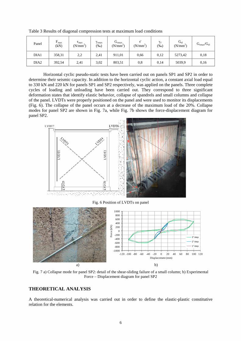
Horizontal cyclic pseudo-static tests have been carried out on panels SP1 and SP2 in order to determine their seismic capacity. In addition to the horizontal cyclic action, a constant axial load equal to 330 kN and 220 kN for panels SP1 and SP2 respectively, was applied on the panels. Three complete cycles of loading and unloading have been carried out. They correspond to three significant deformation states that identify elastic behavior, collapse of spandrels and small columns and collapse of the panel. LVDTs were properly positioned on the panel and were used to monitor its displacements (Fig. 6). The collapse of the panel occurs at a decrease of the maximum load of the 20%. Collapse modes for panel SP2 are shown in Fig. 7a, while Fig. 7b shows the force-displacement diagram for panel SP2.
Fig. 6 Position of LVDTs on panel
-1000
-800
-600
-400
-200
0
200
400
600
800
1000
-120 -100 -80 -60 -40 -20 0 20 40 60 80 100 120
Fo
rce
(kN
)
Displacement (mm)
3° step
2° step
1° step
a) b)
Fig. 7 a) Collapse mode for panel SP2: detail of the shear-sliding failure of a small column; b) Experimental Force – Displacement diagram for panel SP2
THEORETICAL ANALYSIS A theoretical-numerical analysis was carried out in order to define the elastic-plastic constitutive relation for the elements.
7
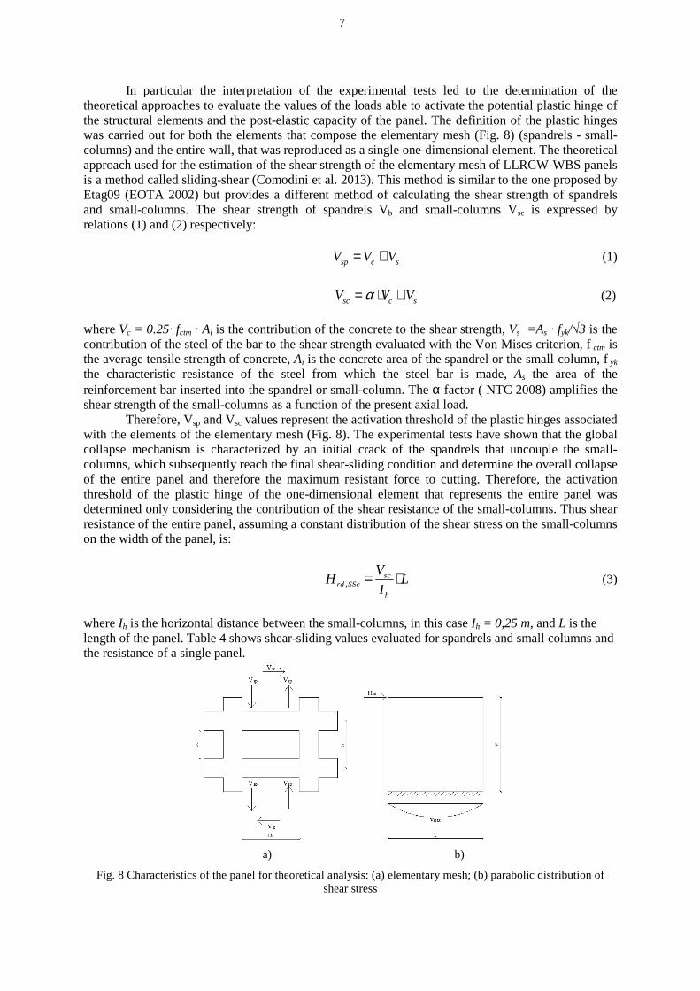
In particular the interpretation of the experimental tests led to the determination of the theoretical approaches to evaluate the values of the loads able to activate the potential plastic hinge of the structural elements and the post-elastic capacity of the panel. The definition of the plastic hinges was carried out for both the elements that compose the elementary mesh (Fig. 8) (spandrels - small-columns) and the entire wall, that was reproduced as a single one-dimensional element. The theoretical approach used for the estimation of the shear strength of the elementary mesh of LLRCW-WBS panels is a method called sliding-shear (Comodini et al. 2013). This method is similar to the one proposed by Etag09 (EOTA 2002) but provides a different method of calculating the shear strength of spandrels and small-columns. The shear strength of spandrels Vb and small-columns Vsc is expressed by relations (1) and (2) respectively: sp c sV V V= + (1)
sc c sV V Vα= ⋅ + (2)
where Vc = 0.25· fctm · Ai is the contribution of the concrete to the shear strength, Vs =As · fyk/√3 is the contribution of the steel of the bar to the shear strength evaluated with the Von Mises criterion, f ctm is the average tensile strength of concrete, Ai is the concrete area of the spandrel or the small-column, f yk the characteristic resistance of the steel from which the steel bar is made, As the area of the reinforcement bar inserted into the spandrel or small-column. The α factor ( NTC 2008) amplifies the shear strength of the small-columns as a function of the present axial load. Therefore, Vsp and Vsc values represent the activation threshold of the plastic hinges associated with the elements of the elementary mesh (Fig. 8). The experimental tests have shown that the global collapse mechanism is characterized by an initial crack of the spandrels that uncouple the small-columns, which subsequently reach the final shear-sliding condition and determine the overall collapse of the entire panel and therefore the maximum resistant force to cutting. Therefore, the activation threshold of the plastic hinge of the one-dimensional element that represents the entire panel was determined only considering the contribution of the shear resistance of the small-columns. Thus shear resistance of the entire panel, assuming a constant distribution of the shear stress on the small-columns on the width of the panel, is:
,sc
rd SSch
VH L
I= ⋅ (3)
where Ih is the horizontal distance between the small-columns, in this case Ih = 0,25 m, and L is the length of the panel. Table 4 shows shear-sliding values evaluated for spandrels and small columns and the resistance of a single panel.
a) b)
Fig. 8 Characteristics of the panel for theoretical analysis: (a) elementary mesh; (b) parabolic distribution of shear stress
8
Table 4 Resistance values for a single LLRCW-WBS panel
Panel Vsp(kN) Vsc (kN) Hrd,SSc (kN)
Unitary size 29,41 38,30 153,20
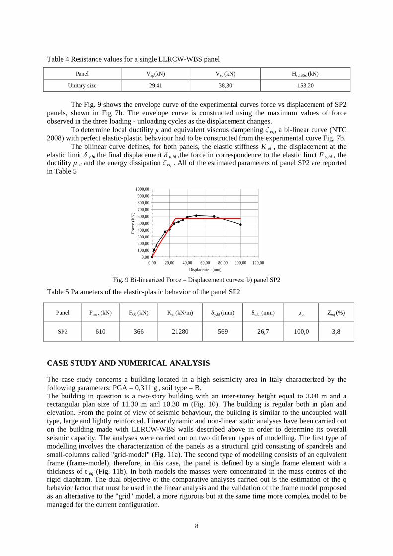
The Fig. 9 shows the envelope curve of the experimental curves force vs displacement of SP2 panels, shown in Fig 7b. The envelope curve is constructed using the maximum values of force observed in the three loading - unloading cycles as the displacement changes. To determine local ductility µ and equivalent viscous dampening ζ eq, a bi-linear curve (NTC 2008) with perfect elastic-plastic behaviour had to be constructed from the experimental curve Fig. 7b. The bilinear curve defines, for both panels, the elastic stiffness K el , the displacement at the elastic limit δ y,bl the final displacement δ u,bl ,the force in correspondence to the elastic limit F y,bl , the ductility µ bl and the energy dissipation ζ eq . All of the estimated parameters of panel SP2 are reported in Table 5
0,00
100,00
200,00
300,00
400,00
500,00
600,00
700,00
800,00
900,00
1000,00
0,00 20,00 40,00 60,00 80,00 100,00 120,00
Fo
rce
(kN
)
Displacement (mm)
Fig. 9 Bi-linearized Force – Displacement curves: b) panel SP2
Table 5 Parameters of the elastic-plastic behavior of the panel SP2
Panel Fmax (kN) F60 (kN) Kel (kN/m) δy,bl (mm) δu,bl (mm) µbl Ζeq (%)
SP2 610 366 21280 569 26,7 100,0 3,8
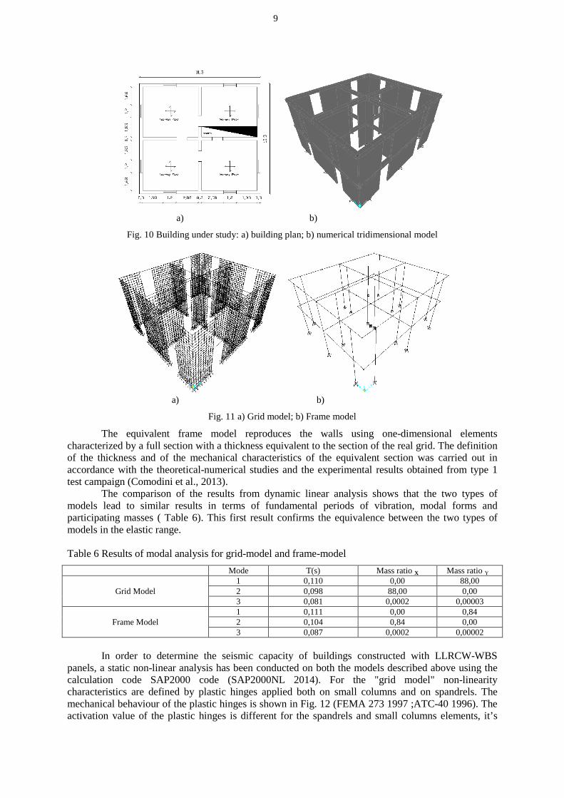
CASE STUDY AND NUMERICAL ANALYSIS The case study concerns a building located in a high seismicity area in Italy characterized by the following parameters: PGA = 0,311 g , soil type = B. The building in question is a two-story building with an inter-storey height equal to 3.00 m and a rectangular plan size of 11.30 m and 10.30 m (Fig. 10). The building is regular both in plan and elevation. From the point of view of seismic behaviour, the building is similar to the uncoupled wall type, large and lightly reinforced. Linear dynamic and non-linear static analyses have been carried out on the building made with LLRCW-WBS walls described above in order to determine its overall seismic capacity. The analyses were carried out on two different types of modelling. The first type of modelling involves the characterization of the panels as a structural grid consisting of spandrels and small-columns called "grid-model" (Fig. 11a). The second type of modelling consists of an equivalent frame (frame-model), therefore, in this case, the panel is defined by a single frame element with a thickness of t eq (Fig. 11b). In both models the masses were concentrated in the mass centres of the rigid diaphram. The dual objective of the comparative analyses carried out is the estimation of the q behavior factor that must be used in the linear analysis and the validation of the frame model proposed as an alternative to the "grid" model, a more rigorous but at the same time more complex model to be managed for the current configuration.
9
a) b)
Fig. 10 Building under study: a) building plan; b) numerical tridimensional model
a) b)
Fig. 11 a) Grid model; b) Frame model
The equivalent frame model reproduces the walls using one-dimensional elements characterized by a full section with a thickness equivalent to the section of the real grid. The definition of the thickness and of the mechanical characteristics of the equivalent section was carried out in accordance with the theoretical-numerical studies and the experimental results obtained from type 1 test campaign (Comodini et al., 2013). The comparison of the results from dynamic linear analysis shows that the two types of models lead to similar results in terms of fundamental periods of vibration, modal forms and participating masses ( Table 6). This first result confirms the equivalence between the two types of models in the elastic range.
Table 6 Results of modal analysis for grid-model and frame-model
Mode T(s) Mass ratio X Mass ratio Y
Grid Model 1 0,110 0,00 88,00 2 0,098 88,00 0,00 3 0,081 0,0002 0,00003
Frame Model 1 0,111 0,00 0,84 2 0,104 0,84 0,00 3 0,087 0,0002 0,00002
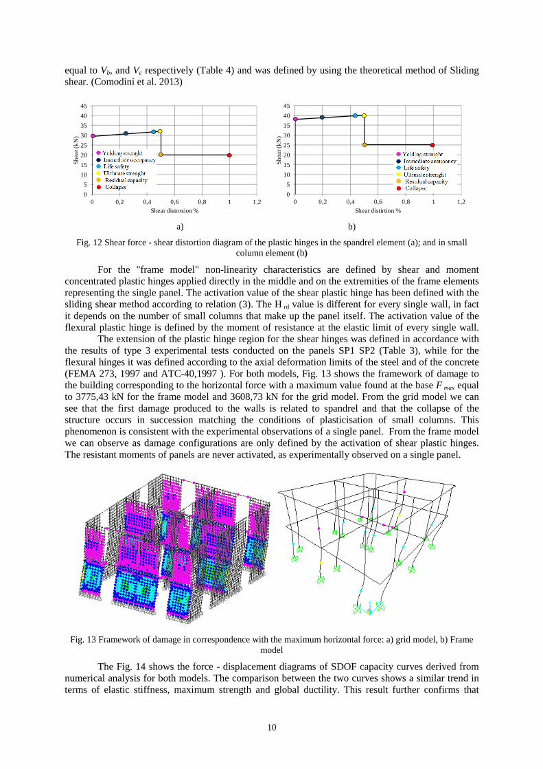
In order to determine the seismic capacity of buildings constructed with LLRCW-WBS panels, a static non-linear analysis has been conducted on both the models described above using the calculation code SAP2000 code (SAP2000NL 2014). For the "grid model" non-linearity characteristics are defined by plastic hinges applied both on small columns and on spandrels. The mechanical behaviour of the plastic hinges is shown in Fig. 12 (FEMA 273 1997 ;ATC-40 1996). The activation value of the plastic hinges is different for the spandrels and small columns elements, it’s
10
equal to Vb, and Vc respectively (Table 4) and was defined by using the theoretical method of Sliding shear. (Comodini et al. 2013)
0
5
10
15
20
25
30
35
40
45
0 0,2 0,4 0,6 0,8 1 1,2
Sh
ea
r (k
N)
Shear distorsion %
0
5
10
15
20
25
30
35
40
45
0 0,2 0,4 0,6 0,8 1 1,2
Sh
ea
r (k
N)
Shear distirtion %
a) b)
Fig. 12 Shear force - shear distortion diagram of the plastic hinges in the spandrel element (a); and in small column element (b)
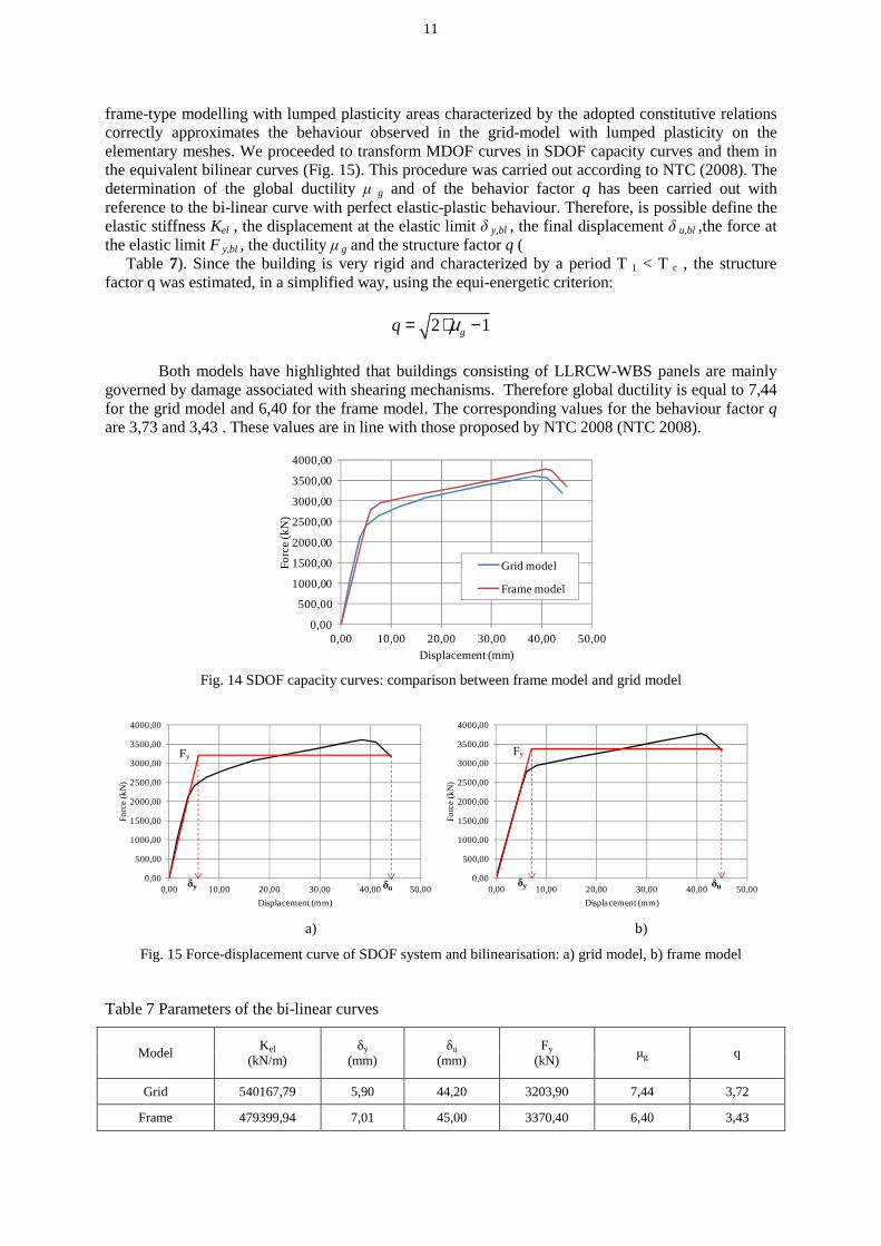
For the "frame model" non-linearity characteristics are defined by shear and moment concentrated plastic hinges applied directly in the middle and on the extremities of the frame elements representing the single panel. The activation value of the shear plastic hinge has been defined with the sliding shear method according to relation (3). The H rd value is different for every single wall, in fact it depends on the number of small columns that make up the panel itself. The activation value of the flexural plastic hinge is defined by the moment of resistance at the elastic limit of every single wall. The extension of the plastic hinge region for the shear hinges was defined in accordance with the results of type 3 experimental tests conducted on the panels SP1 SP2 (Table 3), while for the flexural hinges it was defined according to the axial deformation limits of the steel and of the concrete (FEMA 273, 1997 and ATC-40,1997 ). For both models, Fig. 13 shows the framework of damage to the building corresponding to the horizontal force with a maximum value found at the base F max equal to 3775,43 kN for the frame model and 3608,73 kN for the grid model. From the grid model we can see that the first damage produced to the walls is related to spandrel and that the collapse of the structure occurs in succession matching the conditions of plasticisation of small columns. This phenomenon is consistent with the experimental observations of a single panel. From the frame model we can observe as damage configurations are only defined by the activation of shear plastic hinges. The resistant moments of panels are never activated, as experimentally observed on a single panel.
Fig. 13 Framework of damage in correspondence with the maximum horizontal force: a) grid model, b) Frame model
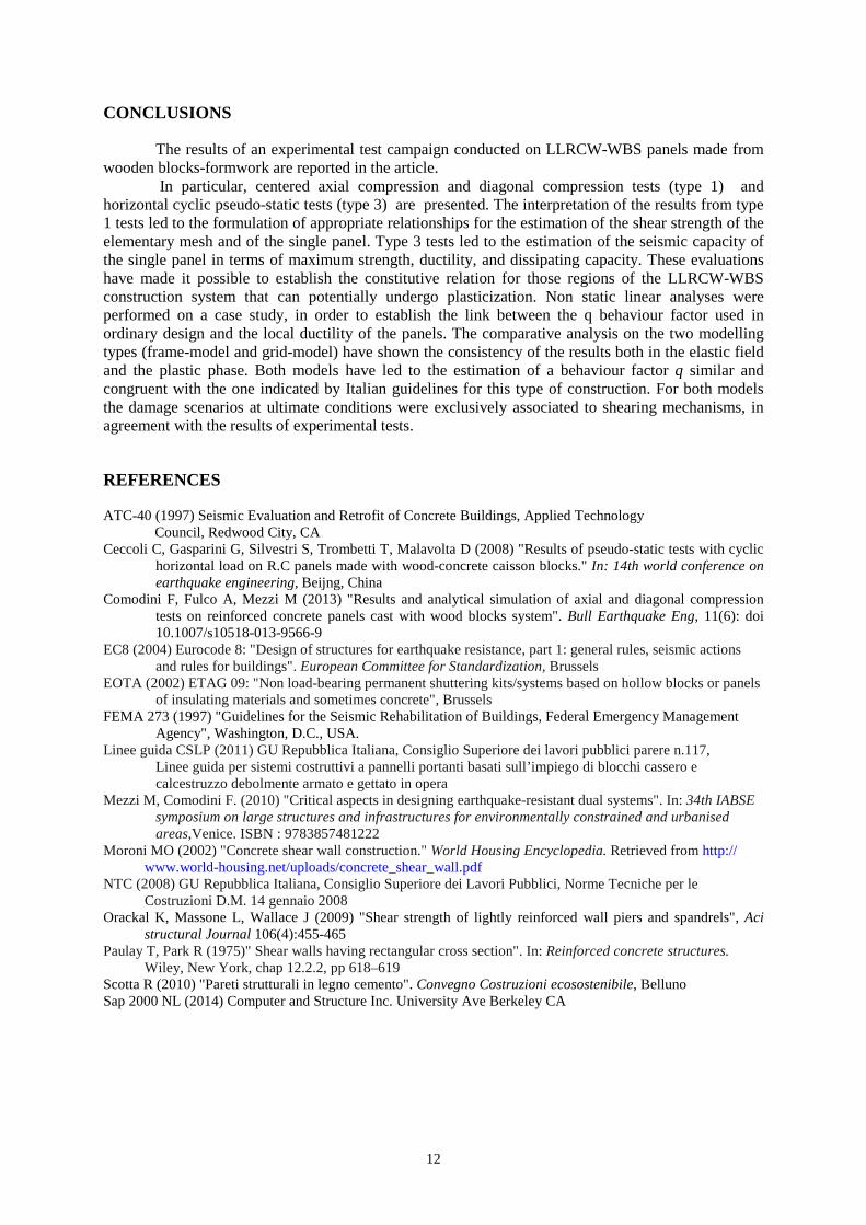
The Fig. 14 shows the force - displacement diagrams of SDOF capacity curves derived from numerical analysis for both models. The comparison between the two curves shows a similar trend in terms of elastic stiffness, maximum strength and global ductility. This result further confirms that
11
frame-type modelling with lumped plasticity areas characterized by the adopted constitutive relations correctly approximates the behaviour observed in the grid-model with lumped plasticity on the elementary meshes. We proceeded to transform MDOF curves in SDOF capacity curves and them in the equivalent bilinear curves (Fig. 15). This procedure was carried out according to NTC (2008). The determination of the global ductility µ g and of the behavior factor q has been carried out with reference to the bi-linear curve with perfect elastic-plastic behaviour. Therefore, is possible define the elastic stiffness Kel , the displacement at the elastic limit δ y,bl , the final displacement δ u,bl ,the force at the elastic limit F y,bl , the ductility µ g and the structure factor q (
Table 7). Since the building is very rigid and characterized by a period T 1 < T c , the structure factor q was estimated, in a simplified way, using the equi-energetic criterion:
2 1gq µ= ⋅ −
Both models have highlighted that buildings consisting of LLRCW-WBS panels are mainly
governed by damage associated with shearing mechanisms. Therefore global ductility is equal to 7,44 for the grid model and 6,40 for the frame model. The corresponding values for the behaviour factor q are 3,73 and 3,43 . These values are in line with those proposed by NTC 2008 (NTC 2008).
0,00
500,00
1000,00
1500,00
2000,00
2500,00
3000,00
3500,00
4000,00
0,00 10,00 20,00 30,00 40,00 50,00
Fo
rce
(kN
)
Displacement (mm)
Grid model
Frame model
Fig. 14 SDOF capacity curves: comparison between frame model and grid model
0,00
500,00
1000,00
1500,00
2000,00
2500,00
3000,00
3500,00
4000,00
0,00 10,00 20,00 30,00 40,00 50,00
Fo
rce
(kN
)
Displacement (mm)
δy δu0,00
500,00
1000,00
1500,00
2000,00
2500,00
3000,00
3500,00
4000,00
0,00 10,00 20,00 30,00 40,00 50,00
Fo
rce
(kN
)
Displacement (mm)
δy δu
a) b)
Fig. 15 Force-displacement curve of SDOF system and bilinearisation: a) grid model, b) frame model
Table 7 Parameters of the bi-linear curves
Model Kel
(kN/m) δy
(mm) δu
(mm) Fy
(kN) µg q
Grid 540167,79 5,90 44,20 3203,90 7,44 3,72
Frame 479399,94 7,01 45,00 3370,40 6,40 3,43
Fy Fy
12
CONCLUSIONS
The results of an experimental test campaign conducted on LLRCW-WBS panels made from wooden blocks-formwork are reported in the article. In particular, centered axial compression and diagonal compression tests (type 1) and horizontal cyclic pseudo-static tests (type 3) are presented. The interpretation of the results from type 1 tests led to the formulation of appropriate relationships for the estimation of the shear strength of the elementary mesh and of the single panel. Type 3 tests led to the estimation of the seismic capacity of the single panel in terms of maximum strength, ductility, and dissipating capacity. These evaluations have made it possible to establish the constitutive relation for those regions of the LLRCW-WBS construction system that can potentially undergo plasticization. Non static linear analyses were performed on a case study, in order to establish the link between the q behaviour factor used in ordinary design and the local ductility of the panels. The comparative analysis on the two modelling types (frame-model and grid-model) have shown the consistency of the results both in the elastic field and the plastic phase. Both models have led to the estimation of a behaviour factor q similar and congruent with the one indicated by Italian guidelines for this type of construction. For both models the damage scenarios at ultimate conditions were exclusively associated to shearing mechanisms, in agreement with the results of experimental tests.
REFERENCES
ATC-40 (1997) Seismic Evaluation and Retrofit of Concrete Buildings, Applied Technology Council, Redwood City, CA
Ceccoli C, Gasparini G, Silvestri S, Trombetti T, Malavolta D (2008) "Results of pseudo-static tests with cyclic horizontal load on R.C panels made with wood-concrete caisson blocks." In: 14th world conference on earthquake engineering, Beijng, China
Comodini F, Fulco A, Mezzi M (2013) "Results and analytical simulation of axial and diagonal compression tests on reinforced concrete panels cast with wood blocks system". Bull Earthquake Eng, 11(6): doi 10.1007/s10518-013-9566-9
EC8 (2004) Eurocode 8: "Design of structures for earthquake resistance, part 1: general rules, seismic actions and rules for buildings". European Committee for Standardization, Brussels EOTA (2002) ETAG 09: "Non load-bearing permanent shuttering kits/systems based on hollow blocks or panels of insulating materials and sometimes concrete", Brussels FEMA 273 (1997) "Guidelines for the Seismic Rehabilitation of Buildings, Federal Emergency Management Agency", Washington, D.C., USA. Linee guida CSLP (2011) GU Repubblica Italiana, Consiglio Superiore dei lavori pubblici parere n.117, Linee guida per sistemi costruttivi a pannelli portanti basati sull’impiego di blocchi cassero e calcestruzzo debolmente armato e gettato in opera Mezzi M, Comodini F. (2010) "Critical aspects in designing earthquake-resistant dual systems". In: 34th IABSE symposium on large structures and infrastructures for environmentally constrained and urbanised areas,Venice. ISBN : 9783857481222 Moroni MO (2002) "Concrete shear wall construction." World Housing Encyclopedia. Retrieved from http:// www.world-housing.net/uploads/concrete_shear_wall.pdf NTC (2008) GU Repubblica Italiana, Consiglio Superiore dei Lavori Pubblici, Norme Tecniche per le Costruzioni D.M. 14 gennaio 2008 Orackal K, Massone L, Wallace J (2009) "Shear strength of lightly reinforced wall piers and spandrels", Aci
structural Journal 106(4):455-465 Paulay T, Park R (1975)" Shear walls having rectangular cross section". In: Reinforced concrete structures. Wiley, New York, chap 12.2.2, pp 618–619 Scotta R (2010) "Pareti strutturali in legno cemento". Convegno Costruzioni ecosostenibile, Belluno Sap 2000 NL (2014) Computer and Structure Inc. University Ave Berkeley CA