fr-a500 instruction manual - amazon s3instruction manual fr-a500 outline chapter 1 installation and...
TRANSCRIPT

TRANSISTORIZE
INSTRUCTION MFR-A500
FR-A520-0.4K toFR-A540-0.4K to
HIGH FUN&
LOW ACOUS
FR-A
500-NA
,-EC TRANSISTORIZED INVERTER
INSTRUCTION MANUAL
HEAD OFFICE:MITSUBISHI DENKI BLDG MARUNOUCHI TOKYO 100-8310
IB(NA)-66790-J (0502) MDOC Printed in japan Specifications subject to change without notice.
D INV
ANUA
55K-N 55K-N
CTION
TIC NOISE
ERTER
L
OUTLINE Chapter 1
INSTALLATIONAND WIRING Chapter 2
OPERATION/CONTROL Chapter 3
PARAMETERS Chapter 4
AA,-EC
PROTECTIVEFUNCTIONS Chapter 5
SPECIFICATIONS Chapter 7
OPTIONS Chapter 8
PRECAUTIONS FORMAINTENANCE AND
INSPECTIONChapter 6

Thank you for choosing this Mitsubishi transistorized Inverter.This instruction manual gives handling information and precautions for use of this equipment.Incorrect handling might cause an unexpected fault. Before using the inverter, please read this manual carefully to use theequipment to its optimum.Please forward this manual to the end user.This instruction manual uses the International System of Units (SI). The measuring units in the yard and pound system areindicated in parentheses as reference values.
1. Electric Shock Prevention
2. Fire Prevention
3. Injury Prevention
This section is specifically about safety mattersDo not attempt to install, operate, maintain or inspect the inverter until you have read through this instruction manual andappended documents carefully and can use the equipment correctly.Do not use the inverter until you have a full knowledge of the equipment, safety information and instructions.In this instruction manual, the safety instruction levels are classified into "WARNING" and "CAUTION".
Assumes that incorrect handling may cause hazardous conditions, resulting in death or severeinjury.
Assumes that incorrect handling may cause hazardous conditions, resulting in medium orslight injury, or may cause physical damage only.
Note that the level may lead to a serious consequence according to conditions. Please follow the instructions of bothlevels because they are important to personnel safety.
WARNING While power is on or when the inverter is running, do not open the front cover. You may get an electric shock. Do not run the inverter with the front cover removed. Otherwise, you may access the exposed high-voltage terminals or the
charging part of the circuitry and get an electric shock. Even if power is off, do not remove the front cover except for wiring or periodic inspection. You may access the charged inverter
circuits and get an electric shock. Before starting wiring or inspection, check to make sure that the inverter power indicator lamp is off, wait for at least 10 minutes
after the power supply has been switched off, and check that there are no residual voltage using a tester or the like. The capacitor ischarged with high voltage for some time after power off and it is dangerous.
This inverter must be earthed (grounded). Earthing (grounding) must conform to the requirements of national and local safetyregulations and electrical code. (JIS, NEC section 250, IEC 536 class 1 and other applicable standards)
Any person who is involved in the wiring or inspection of this equipment should be fully competent to do the work. Always install the inverter before wiring. Otherwise, you may get an electric shock or be injured. Perform setting dial and key operations with dry hands to prevent an electric shock. Do not subject the cables to scratches, excessive stress, heavy loads or pinching. Otherwise, you may get an electric shock. Do not change the cooling fan while power is on. To do so will invite a hazardous condition.
CAUTION Mount the inverter on an incombustible surface. Installing the inverter directly on or near a combustible surface could lead to a fire. If the inverter has become faulty, switch off the inverter power. A continuous flow of large current could cause a fire. When using a brake resistor, make up a sequence that will turn off power when an alarm signal is output. Otherwise, the brake
resistor may excessively overheat due to damage of the brake transistor and such, causing a fire. Do not connect a resistor directly to the DC terminals P/+, N/-. This could cause a fire.
CAUTION Apply only the voltage specified in the instruction manual to each terminal to prevent damage etc. Ensure that the cables are connected to the correct terminals. Otherwise, damage etc. may occur. Always make sure that polarity is correct to prevent damage etc. While power is on and for some time after power-off, do not touch the inverter as it is hot and you may get burnt.
WARNING
CAUTION
CAUTION
A-1

4. Additional InstructionsAlso note the following points to prevent an accidental failure, injury, electric shock, etc.
(1) Transportation and installation
(2) Wiring
(3) Trial run
(4) Operation
CAUTION When carrying products, use correct lifting gear to prevent injury. Do not stack the inverter boxes higher than the number recommended. Ensure that installation position and material can withstand the weight of the inverter. Install according to the information in the
Instruction Manual. Do not operate if the inverter is damaged or has parts missing. Do not hold the inverter by the front cover; it may fall off. Do not stand or rest heavy objects on the inverter. Check the inverter mounting orientation is correct. Prevent screws, wire fragments, conductive bodies, oil or other flammable substances from entering the inverter. Do not drop the inverter, or subject it to impact. Use the inverter under the following environmental conditions:
Env
ironm
ent
Ambient temperature-10°C to +50°C (14°F to 122°F) (non-freezing)
(-10°C to +40°C with totally ecclosed structure specification attachment (FR-A5CV))(14°F to 104°F)
Ambient humidity 90%RH or less (non-condensing)Storage temperature -20°C to +65°C* (-4°F to 149°F)Ambience Indoors (free from corrosive gas, flammable gas, oil mist, dust and dirt)
Altitude, vibration
Maximum 1000m (3280.80 feet.) above sea level for standard operation.After that derate by 3% for every extra 500m(1640.40 feet.) up to 2500m(8202.00 feet.)(91%).5.9 m/s2 or less (conforming to JIS C 60068-2-6)
*Temperatures applicable for a short time, e.g. in transit.
CAUTION Do not fit capacitive equipment such as a power factor correction capacitor, surge suppressor or radio noise filter (option FR-BIF)
to the inverter output side. The connection orientation of the output cables (terminals U, V, W) to the motor will affect the direction of rotation of the motor.
CAUTION Check all parameters, and ensure that the machine will not be damaged by a sudden start-up.
WARNING When you have chosen the retry function, stay away from the equipment as it will restart suddenly after an alarm stop. The [STOP] key is valid only when the appropriate function setting has been made. Prepare an emergency stop switch separately. Make sure that the start signal is off before resetting the inverter alarm. A failure to do so may restart the motor suddenly. The load used should be a three-phase induction motor only. Connection of any other electrical equipment to the inverter output
may damage the equipment. Do not modify the equipment. Do not perform parts removal which is not instructed in this manual. Doing so may lead to fault or damage of the inverter.
CAUTION The electronic thermal relay function does not guarantee protection of the motor from overheating. Do not use a magnetic contactor on the inverter input for frequent starting/stopping of the inverter. Use a noise filter to reduce the effect of electromagnetic interference. Otherwise nearby electronic equipment may be affected. Take measures to suppress harmonics. Otherwise power supply harmonics from the inverter may heat/damage the power capacitor
and generator. When a 400V class motor is inverter-driven, please use an insulation-enhanced motor or measure taken to suppress surge
voltages. Surge voltages attributable to the wiring constants may occur at the motor terminals, deteriorating the insulation of themotor.
When parameter clear or all clear is performed, each parameter returns to the factory setting. Re-set the required parametersbefore starting operation.
The inverter can be easily set for high-speed operation. Before changing its setting, examine the performance of the motor andmachine.
In addition to the inverter's holding function, install a holding device to ensure safety. Before running an inverter which had been stored for a long period, always perform inspection and test operation.
A-2
(5) Emergency stop
(6) Maintenance, inspection and parts replacement
(7) Disposing of the inverter
(8) General instructions
CAUTION Provide a safety backup such as an emergency brake which will prevent the machine and equipment from hazardous conditions if
the inverter fails. When the breaker on the inverter primary side trips, check for the wiring fault (short circuit), damage to internal parts of the inverter,
etc. Identify the cause of the trip, then remove the cause and power on the breaker. When any protective function is activated, take the appropriate corrective action, then reset the inverter, and resume operation.
CAUTION Do not carry out a megger (insulation resistance) test on the control circuit of the inverter.
CAUTION Treat as industrial waste.
Many of the diagrams and drawings in this instruction manual show the inverter without a cover, or partially open. Never runthe inverter in this manner. Always replace the cover and follow this instruction manual when operating the inverter.
A-3

CONTENTS
CHAPTER 1 OUTLINE 11.1 Pre-Operation Information .................................................................................. 21.1.1 Precautions for operation ...................................................................................................................2
1.2 Basic Configuration............................................................................................. 31.2.1 Basic configuration.............................................................................................................................3
1.3 Structure ............................................................................................................... 41.3.1 Appearance and structure ..................................................................................................................41.3.2 Removal and reinstallation of the front cover .....................................................................................51.3.3 Removal and reinstallation of the operation panel .............................................................................7
CHAPTER 2 INSTALLATION AND WIRING 9
2.1 Installation .......................................................................................................... 102.1.1 Instructions for installation................................................................................................................10
2.2 Wiring.................................................................................................................. 122.2.1 Terminal connection diagram...........................................................................................................122.2.2 Wiring of the main circuit ..................................................................................................................152.2.3 Wiring of the control circuit ...............................................................................................................212.2.4 Connection to the PU connector ......................................................................................................252.2.5 Connection of stand-alone option units ............................................................................................282.2.6 Design information ...........................................................................................................................33
2.3 Other wiring........................................................................................................ 342.3.1 Power supply harmonics ..................................................................................................................342.3.2 Inverter-generated noises and their reduction techniques ...............................................................342.3.3 Leakage currents and countermeasures..........................................................................................372.3.4 Inverter-driven 400V class motor .....................................................................................................382.3.5 Peripheral devices............................................................................................................................392.3.6 Instructions for UL and cUL..............................................................................................................422.3.7 Instructions for compliance with the European Directives................................................................432.3.8 Earthing (EC version) .......................................................................................................................45
CHAPTER 3 OPERATION/CONTROL 47
3.1 Pre-Operation Information ................................................................................ 483.1.1 Devices and parts to be prepared for operation ...............................................................................483.1.2 Power on ..........................................................................................................................................50
3.2 Operation Panel ................................................................................................. 513.2.1 Names and functions of the operation panel (FR-DU04) .................................................................513.2.2 Monitor display changed by pressing the key .................................................................................523.2.3 Monitoring.........................................................................................................................................523.2.4 Frequency setting.............................................................................................................................523.2.5 Parameter setting method................................................................................................................533.2.6 Operation mode................................................................................................................................543.2.7 Help mode........................................................................................................................................543.2.8 Copy mode.......................................................................................................................................56
3.3 Operation ............................................................................................................ 573.3.1 Pre-operation checks .......................................................................................................................57
I

Con
tent
s
3.3.2 External operation mode (Operation using external input signals)...................................................583.3.3 PU operation mode
(Operation using the operation panel (FR-DU04)) ..........................................................................593.3.4 Combined operation mode
(Operation using the external input signals and PU)........................................................................60
CHAPTER 4 PARAMETERS 61
4.1 Parameter Lists .................................................................................................. 624.1.1 Parameter lists .................................................................................................................................624.1.2 List of parameters classified by purpose of use ...............................................................................694.1.3 Parameters recommended to be set by the user .............................................................................70
4.2 Parameter Function Details .............................................................................. 714.2.1 Torque boost (Pr. 0, Pr. 46, Pr. 112) ................................................................................................714.2.2 Output frequency range (Pr. 1, Pr. 2, Pr. 18) ...................................................................................724.2.3 Base frequency, base frequency voltage (Pr. 3, Pr. 19, Pr. 47, Pr. 113) .........................................734.2.4 Multi-speed operation (Pr. 4 to Pr. 6, Pr. 24 to Pr. 27, Pr. 232 to Pr. 239).......................................744.2.5 Acceleration/deceleration time (Pr. 7, Pr. 8, Pr. 20, Pr. 21, Pr. 44, Pr. 45, Pr. 110, Pr. 111) ..........754.2.6 Electronic overcurrent protection (Pr. 9)...........................................................................................764.2.7 DC injection brake (Pr. 10 to Pr. 12) ................................................................................................774.2.8 Starting frequency (Pr. 13) ...............................................................................................................784.2.9 Load pattern selection (Pr. 14) .........................................................................................................794.2.10 Jog operation (Pr. 15, Pr. 16) ...........................................................................................................804.2.11 MRS input selection (Pr. 17) ............................................................................................................814.2.12 Stall prevention (Pr. 22, Pr. 23, Pr. 66, Pr. 148, Pr. 149, Pr. 154)....................................................824.2.13 Multi-speed input compensation (Pr. 28)..........................................................................................834.2.14 Acceleration/deceleration pattern (Pr. 29, Pr. 140 to Pr. 143)..........................................................844.2.15 Regenerative brake duty (Pr. 30, Pr. 70)..........................................................................................854.2.16 Frequency jump (Pr. 31 to Pr. 36) ....................................................................................................864.2.17 Speed display (Pr. 37, Pr. 144) ........................................................................................................874.2.18 Up-to-frequency sensitivity (Pr. 41) ..................................................................................................884.2.19 Output frequency detection (Pr. 42, Pr. 43, Pr. 50, Pr. 116) ............................................................884.2.20 Second/third stall prevention (Pr. 48, Pr. 49, Pr. 114, Pr. 115) ........................................................894.2.21 Monitor display/FM, AM terminal function selection (Pr. 52 to Pr. 54, Pr. 158)................................904.2.22 Monitoring reference (Pr. 55, Pr. 56)................................................................................................934.2.23 Automatic restart after instantaneous power failure (Pr. 57, Pr. 58, Pr. 162, Pr. 165, Pr. 611).......944.2.24 Remote setting function selection (Pr. 59) .......................................................................................964.2.25 Intelligent mode selection (Pr. 60)....................................................................................................984.2.26 Acceleration/deceleration reference current (Pr. 61 to Pr. 64) .......................................................1004.2.27 Retry function (Pr. 65, Pr. 67 to Pr. 69) ..........................................................................................1014.2.28 Applied motor (Pr. 71) ....................................................................................................................1034.2.29 PWM carrier frequency (Pr. 72, Pr. 240) ........................................................................................1044.2.30 Voltage input (Pr. 73) .....................................................................................................................1054.2.31 Input filter time constant (Pr. 74) ....................................................................................................1064.2.32 Reset selection/disconnected PU detection/PU stop selection (Pr. 75) .........................................1064.2.33 Alarm code output selection (Pr. 76) ..............................................................................................1084.2.34 Parameter write disable selection (Pr. 77) .....................................................................................1094.2.35 Reverse rotation prevention selection (Pr. 78) ...............................................................................1104.2.36 Operation mode selection (Pr. 79) .................................................................................................1114.2.37 Motor capacity/number of motor poles/speed control gain (Pr. 80, Pr. 81, Pr. 89) ........................1144.2.38 Offline auto tuning function (Pr. 82 to Pr. 84, Pr. 90 to Pr. 94, Pr. 96) ...........................................1154.2.39 Online auto tuning selection (Pr. 95) ..............................................................................................123
II
4.2.40 V/F control frequency (voltage) (Pr. 100 to Pr. 109).......................................................................1254.2.41 Computer link operation (Pr. 117 to Pr. 124, Pr. 342) ....................................................................1264.2.42 PID control (Pr. 128 to Pr. 134) ......................................................................................................1374.2.43 Commercial power supply-inverter switchover function (Pr. 135 to Pr. 139)..................................1444.2.44 Output current detection function (Pr. 150, Pr. 151).......................................................................1494.2.45 Zero current detection (Pr. 152, Pr. 153)........................................................................................1504.2.46 RT signal activated condition selection (Pr. 155) ...........................................................................1514.2.47 Stall prevention function and current limit function (Pr. 156)..........................................................1514.2.48 OL signal output timer (Pr. 157) .....................................................................................................1534.2.49 User group selection (Pr. 160, Pr. 173 to Pr. 176) .........................................................................1544.2.50 Watt-hour meter clear/actual operation hour meter clear (Pr. 170, Pr. 171) ..................................1554.2.51 Input terminal function selection (Pr. 180 to Pr. 186) .....................................................................1554.2.52 Output terminal function selection (Pr. 190 to Pr. 195) ..................................................................1584.2.53 User initial value setting (Pr. 199) ..................................................................................................1604.2.54 Programmed operation function (Pr. 200 to Pr. 231) .....................................................................1614.2.55 Cooling fan operation selection (Pr. 244) .......................................................................................1654.2.56 Stop selection (Pr. 250)..................................................................................................................1664.2.57 Output phase failure protection selection (Pr. 251) ........................................................................1674.2.58 Override bias/gain (Pr. 252, Pr. 253)..............................................................................................1674.2.59 Power failure-time deceleration-to-stop function (Pr. 261 to Pr. 266) ............................................1684.2.60 Stop-on-contact, load torque high-speed frequency selection (Pr. 270) ........................................1694.2.61 High-speed frequency control (Pr. 271 to Pr. 274).........................................................................1704.2.62 Stop-on-contact control function (Pr. 275, Pr. 276) ........................................................................1744.2.63 Brake sequence function (Pr. 278 to Pr. 285) ................................................................................1774.2.64 Droop control (Pr. 286, Pr. 287) .....................................................................................................1814.2.65 Capacitor life alarm (Pr. 503, Pr. 504)............................................................................................1824.2.66 FM / AM terminal calibration (Pr. 900, Pr. 901) .............................................................................1834.2.67 Frequency setting voltage (current) bias and gain (Pr. 902 to Pr. 905)..........................................1854.2.68 PU buzzer control (Pr. 990)............................................................................................................190
CHAPTER 5 PROTECTIVE FUNCTIONS 191
5.1 Errors (Alarms)................................................................................................ 1925.1.1 Error (alarm) definitions..................................................................................................................1925.1.2 To know the operating status at the occurrence of an alarm .........................................................2015.1.3 Correspondences between digital and actual characters...............................................................2015.1.4 Alarm code output ..........................................................................................................................2025.1.5 Resetting the inverter .....................................................................................................................202
5.2 Troubleshooting............................................................................................... 2035.2.1 Motor remains stopped...................................................................................................................2035.2.2 Motor rotates in opposite direction .................................................................................................2035.2.3 Speed greatly differs from the setting.............................................................................................2035.2.4 Acceleration/deceleration is not smooth.........................................................................................2035.2.5 Motor current is large .....................................................................................................................2035.2.6 Speed does not increase................................................................................................................2045.2.7 Speed varies during operation .......................................................................................................2045.2.8 Operation mode is not changed properly .......................................................................................2045.2.9 Operation panel (FR-DU04) display is not provided.......................................................................2045.2.10 POWER lamp is not lit....................................................................................................................2045.2.11 Parameter write cannot be performed............................................................................................204
III
Con
tent
s
CHAPTER 6 PRECAUTIONS FOR MAINTENANCE AND INSPECTION205
6.1 Precautions for maintenance and inspection ............................................... 2066.1.1 Precautions for maintenance and inspection .................................................................................2066.1.2 Check items....................................................................................................................................2066.1.3 Periodic inspection .........................................................................................................................2066.1.4 Insulation resistance test using megger .........................................................................................2076.1.5 Pressure test ..................................................................................................................................2076.1.6 Daily and periodic inspection..........................................................................................................2076.1.7 Replacement of parts .....................................................................................................................2106.1.8 Inverter replacement ......................................................................................................................2116.1.9 Measurement of main circuit voltages, currents and powers .........................................................212
CHAPTER 7 SPECIFICATIONS 215
7.1 Standard Specifications .................................................................................. 2167.1.1 Model specifications .......................................................................................................................2167.1.2 Common specifications ..................................................................................................................2187.1.3 Outline dimension drawings ...........................................................................................................220
CHAPTER 8 OPTIONS 225
8.1 Option List ........................................................................................................ 2268.1.1 Stand-alone options .......................................................................................................................2268.1.2 Plug-in dedicated options ...............................................................................................................228
APPENDICES 239
Appendix1 Instruction Code List............................................................................ 240Appendix2 Operating the Inverter Using a Single-Phase Power Supply............. 247
IV


CHAPTER 1
OUTLINEChapter 1
Chapter 2
Chapter 3
Chapter 4
Chapter 5
Chapter 6
Chapter 7
Chapter 8
This chapter gives information on the basic "outline" of thisproduct.Always read the instructions in this chapter before using theequipment.
1.1 Pre-Operation Information....................................... 21.2 Basic Configuration ................................................. 31.3 Structure .................................................................. 4
<Abbreviations>• DU
Operation panel (FR-DU04)• PU
Operation panel (FR-DU04) and parameter unit (FR-PU04)• Inverter
Mitsubishi transistorized inverter FR-A500 series• Pr.
Parameter number• PU operation
Operation using the PU (FR-DU04/FR-PU04)• External operation
Operation using the control circuit signals• Combined operation
Operation using both the PU (FR-DU04/FR-PU04) and external operation
• FR-A200EMitsubishi transistorized inverter FR-A200 series
<EXCELLENT> series
1
2
OUTLINE
1.1 Pre-Operation Information
1.1.1 Precautions for operationIncorrect handling might cause the inverter to operate improperly, its life to be reduced considerably, or at theworst, the inverter to be damaged. Handle the inverter properly in accordance with the information in eachsection as well as the precautions and instructions of this manual to use it correctly.This manual is written for the FR-A500 series transistorized inverters.For handling information on the parameter unit (FR-PU04), plug-in options, stand-alone options, etc., refer tothe corresponding manuals.
(1) Unpacking and product check
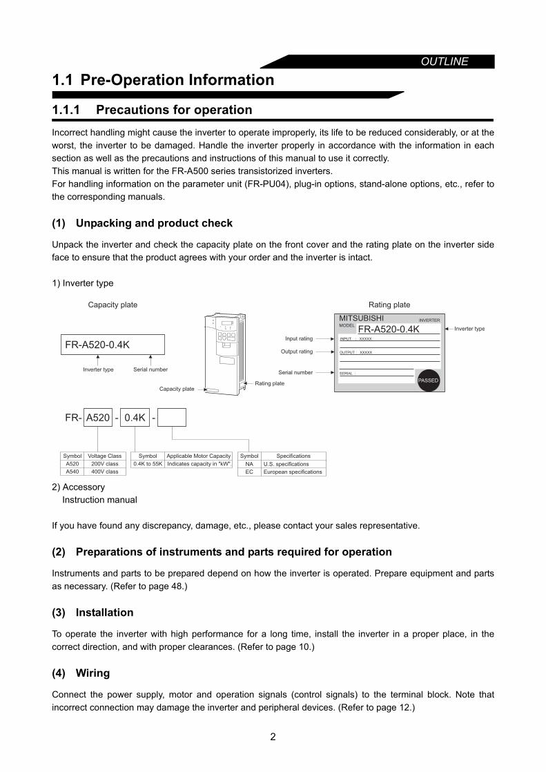
Unpack the inverter and check the capacity plate on the front cover and the rating plate on the inverter sideface to ensure that the product agrees with your order and the inverter is intact.
1) Inverter type
2) AccessoryInstruction manual
If you have found any discrepancy, damage, etc., please contact your sales representative.
(2) Preparations of instruments and parts required for operation
Instruments and parts to be prepared depend on how the inverter is operated. Prepare equipment and partsas necessary. (Refer to page 48.)
(3) Installation
To operate the inverter with high performance for a long time, install the inverter in a proper place, in thecorrect direction, and with proper clearances. (Refer to page 10.)
(4) Wiring
Connect the power supply, motor and operation signals (control signals) to the terminal block. Note thatincorrect connection may damage the inverter and peripheral devices. (Refer to page 12.)
FR-A520-0.4K
Capacity plate
Inverter type Serial number
Capacity plateRating plate
FR- A520 - 0.4K
Symbol Voltage Class
A520
A540
200V class
400V class
Symbol Applicable Motor Capacity
0.4K to 55K Indicates capacity in "kW".
Rating plate
Input rating
Output rating
Serial number
Inverter type
MITSUBISHIMODEL
INVERTER
FR-A520-0.4K INPUT :
OUTPUT :
SERIAL :
XXXXX
XXXXX
PASSED
NA U.S. specifications
EC European specifications
-
Symbol Specifications

3
OUTLINE
1
1.2 Basic Configuration
1.2.1 Basic configurationThe following devices are required to operate the inverter. Proper peripheral devices must be selected and correctconnections made to ensure proper operation. Incorrect system configuration and connections can cause theinverter to operate improperly, its life to be reduced considerably, and in the worst case, the inverter to be damaged.Please handle the inverter properly in accordance with the information in each section as well as the precautions andinstructions of this manual. (For connections of the peripheral devices, refer to the corresponding manuals.)
Name Description
Power supplyUse the power supply within the permissiblepower supply specifications of the inverter.(Refer to page 216.)
Earth leakage circuit breaker (ELB) or moulded case circuit breaker (MCCB)
The breaker should be selected with caresince a large inrush current flows in theinverter at power on. (Refer to page 39.)
Magneticcontactor
Install the magnetic contactor to ensuresafety. (Refer to page 41)Do not use this magnetic contactor to startand stop the inverter. Doing so will cause theinverter life to be shorter.(Refer to page 39.)
Reactors
The reactors must be used when the powerfactor is to be improved or the inverter isinstalled near a large power supply system(1000kVA or more and wiring distance within10m (32.81 feet)). Make selection carefully.
Inverter
• The life of the inverter is influenced byambient temperature. The ambienttemperature should be as low as possiblewithin the permissible range.This must be noted especially when theinverter is installed in an enclosure. (Refer to page 10.)
• Wrong wiring might lead to damage of theinverter. The control signal lines must bekept fully away from the main circuit toprotect them from noise. (Refer to page12.)
Devicesconnected to the output
• Do not install a power factor correctioncapacitor, surge suppressor or radio noisefilter on the output side.
• When installing a moulded case circuitbreaker (MCCB) on the output side of theinverter, contact each manufacturer forselection of the moulded case circuit breaker.
Earth (Ground)
To prevent an electric shock, always earth(ground) the motor and inverter.For reduction of induction noise from thepower line of the inverter, it is recommendedto wire the earth (ground) cable by returningit to the earth (ground) terminal of theinverter. (Refer to page 36.)
(MC)
Earth(Ground)
DC reactor(FR-BEL)
(MCCB) or
(ELB)
AC reactor(FR-BAL)
Earth(Ground)
OUTLINE
1.3 Structure
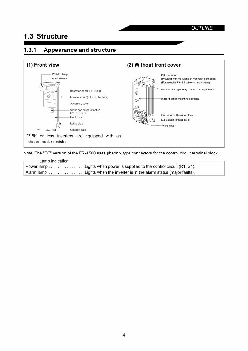
1.3.1 Appearance and structure
Note: The "EC" version of the FR-A500 uses pheonix type connectors for the control circuit terminal block.
(1) Front view
*7.5K or less inverters are equipped with aninboard brake resistor.
(2) Without front cover
Lamp indicationPower lamp . . . . . . . . . . . . . . . .Lights when power is supplied to the control circuit (R1, S1).Alarm lamp . . . . . . . . . . . . . . . .Lights when the inverter is in the alarm status (major faults).
POWER lamp
ALARM lamp
Operation panel (FR-DU04)
Brake resistor* (Fitted to the back)
Accessory cover
Wiring port cover for option
(DATA PORT)
Front cover
Rating plate
Capacity plate
Wiring cover
PU connector(Provided with modular jack type relay connector)(For use with RS-485 cable communication)
Modular jack type relay connector compartment
Inboard option mounting positions
Control circuit terminal block
Main circuit terminal block
4
OUTLINE
1
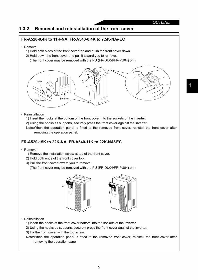
1.3.2 Removal and reinstallation of the front cover
FR-A520-0.4K to 11K-NA, FR-A540-0.4K to 7.5K-NA/-EC
• Removal1) Hold both sides of the front cover top and push the front cover down.2) Hold down the front cover and pull it toward you to remove.
(The front cover may be removed with the PU (FR-DU04/FR-PU04) on.)
• Reinstallation1) Insert the hooks at the bottom of the front cover into the sockets of the inverter.2) Using the hooks as supports, securely press the front cover against the inverter.Note:When the operation panel is fitted to the removed front cover, reinstall the front cover after
removing the operation panel.
FR-A520-15K to 22K-NA, FR-A540-11K to 22K-NA/-EC
• Removal1) Remove the installation screw at top of the front cover.2) Hold both ends of the front cover top.3) Pull the front cover toward you to remove.
(The front cover may be removed with the PU (FR-DU04/FR-PU04) on.)
• Reinstallation1) Insert the hooks at the front cover bottom into the sockets of the inverter.2) Using the hooks as supports, securely press the front cover against the inverter.3) Fix the front cover with the top screw.Note:When the operation panel is fitted to the removed front cover, reinstall the front cover after
removing the operation panel.
Front cover Inverter
hook
5
OUTLINE
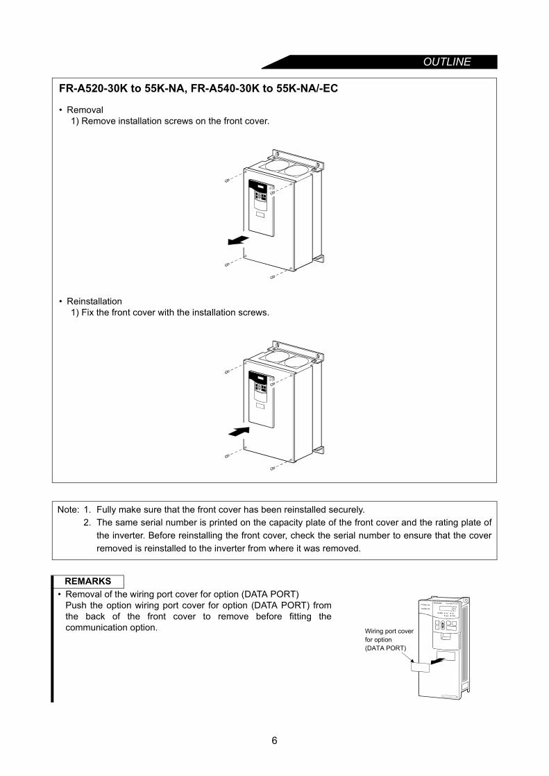
FR-A520-30K to 55K-NA, FR-A540-30K to 55K-NA/-EC
• Removal1) Remove installation screws on the front cover.
• Reinstallation1) Fix the front cover with the installation screws.
Note: 1. Fully make sure that the front cover has been reinstalled securely.2. The same serial number is printed on the capacity plate of the front cover and the rating plate of
the inverter. Before reinstalling the front cover, check the serial number to ensure that the coverremoved is reinstalled to the inverter from where it was removed.
REMARKS• Removal of the wiring port cover for option (DATA PORT)
Push the option wiring port cover for option (DATA PORT) fromthe back of the front cover to remove before fitting thecommunication option. Wiring port cover
for option(DATA PORT)
6

OUTLINE
1
1.3.3 Removal and reinstallation of the operation panelTo ensure safety, remove and reinstall the operation panel after powering off.
• RemovalHold down the top button of the operation panel and pull the operation panel toward you to remove.
When reinstalling the operation panel, insert it straight and reinstall it securely.
• Reinstallation using the connection cable1) Remove the operation panel.2) Disconnect the modular jack type relay connector. (Place the disconnected modular jack type relay
connector in the modular jack type relay connector compartment.)
3) Securely plug one end of the connection cable into the PU connector (modular jack type relayconnector) of the inverter and the other end into the operation panel. (Refer to page 25 for theconnection cable.)
Note: Install the operation panel only when the front cover is on the inverter.
Removal Reinstallation
Modular jack type relay connector compartment
Modular jack type relay connector
7

MEMO
8
CHAPTER 2
INSTALLATION AND WIRINGChapter 1
Chapter 2
Chapter 3
Chapter 4
Chapter 5
Chapter 6
Chapter 7
Chapter 8
This chapter explains the basic "installation and wiring" for useof this product.Always read the instructions and other information before usingthe equipment.
2.1 Installation .............................................................102.2 Wiring ....................................................................122.3 Other wiring ...........................................................34
9
INSTALLATION AND WIRING
2.1 Installation
2.1.1 Instructions for installation1) Handle the unit carefully.
The inverter uses plastic parts. Handle it gently to protect it from damage. Also, hold the unit with evenstrength and do not apply too much strength to the front cover alone.
2) Install the inverter in a place where it is immune to vibration. (5.9 m/s2 or less)Also note the cart, press, etc.
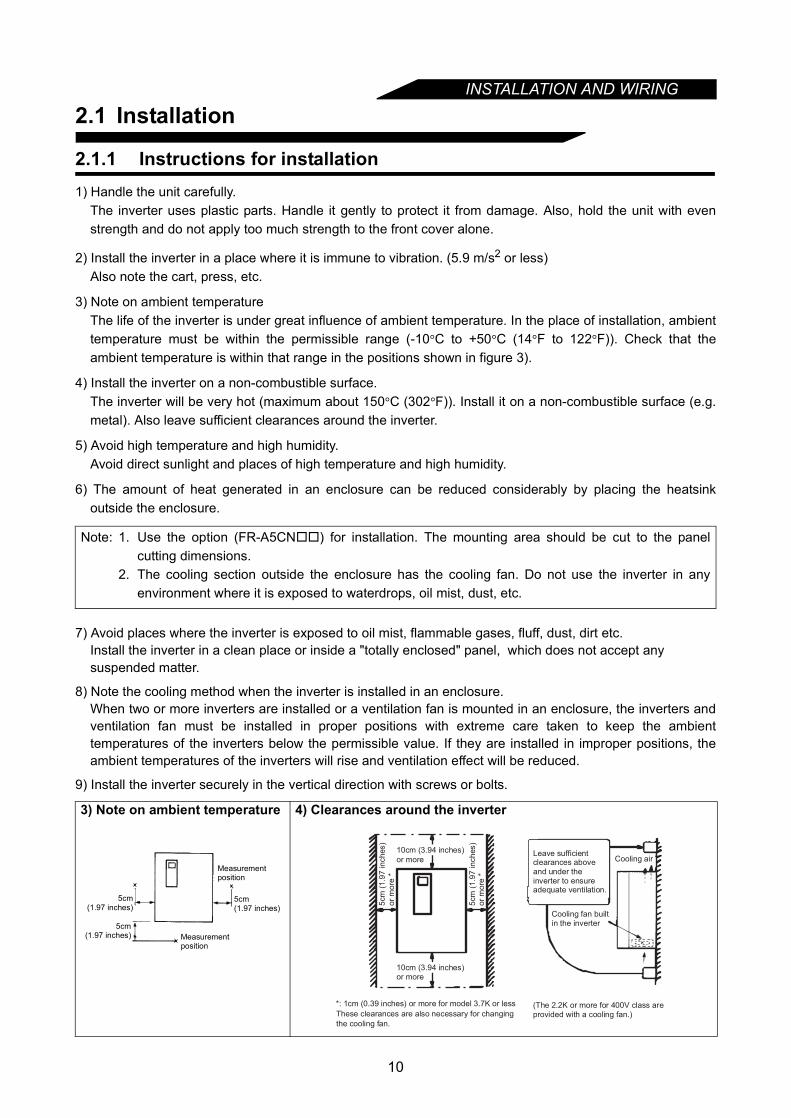
3) Note on ambient temperatureThe life of the inverter is under great influence of ambient temperature. In the place of installation, ambienttemperature must be within the permissible range (-10°C to +50°C (14°F to 122°F)). Check that theambient temperature is within that range in the positions shown in figure 3).
4) Install the inverter on a non-combustible surface.The inverter will be very hot (maximum about 150°C (302°F)). Install it on a non-combustible surface (e.g.metal). Also leave sufficient clearances around the inverter.
5) Avoid high temperature and high humidity.Avoid direct sunlight and places of high temperature and high humidity.
6) The amount of heat generated in an enclosure can be reduced considerably by placing the heatsinkoutside the enclosure.
7) Avoid places where the inverter is exposed to oil mist, flammable gases, fluff, dust, dirt etc.Install the inverter in a clean place or inside a "totally enclosed" panel, which does not accept any suspended matter.
8) Note the cooling method when the inverter is installed in an enclosure.When two or more inverters are installed or a ventilation fan is mounted in an enclosure, the inverters andventilation fan must be installed in proper positions with extreme care taken to keep the ambienttemperatures of the inverters below the permissible value. If they are installed in improper positions, theambient temperatures of the inverters will rise and ventilation effect will be reduced.
9) Install the inverter securely in the vertical direction with screws or bolts.
Note: 1. Use the option (FR-A5CN) for installation. The mounting area should be cut to the panelcutting dimensions.
2. The cooling section outside the enclosure has the cooling fan. Do not use the inverter in anyenvironment where it is exposed to waterdrops, oil mist, dust, etc.
3) Note on ambient temperature 4) Clearances around the inverter
Measurementposition
Measurementposition
5cm(1.97 inches)
5cm(1.97 inches)
5cm(1.97 inches)
Leave sufficientclearances above and under the inverter to ensureadequate ventilation.
Cooling fan builtin the inverter
Cooling air10cm (3.94 inches)
5cm
(1
.97
in
ch
es)
or
mo
re *
*: 1cm (0.39 inches) or more for model 3.7K or less
5cm
(1
.97
in
ch
es)
or
mo
re *
or more
10cm (3.94 inches)or more
These clearances are also necessary for changing
the cooling fan.
(The 2.2K or more for 400V class are provided with a cooling fan.)
10

INSTALLATION AND WIRING
2
(1) Wiring cover and handling (22K or less)
1) When cable conduits are not connectedCut the protective bushes of the wiring cover with nippers or a cutter before running the cables.
2) When cable conduits are connectedRemove the corresponding protective bushes and connect the cable conduits.
8) For installation in an enclosure
9) Vertical mounting
WARNINGDo not remove the protective bushes. Otherwise, the cable sheathes may be scratched by the wiring cover edges, resulting in a short circuit or earth (ground) fault.
Ventilation fan
(Correct example)
Position of Ventilation Fan
Inverter Inverter
Inverter
(Correct example) (Incorrect example)
Built-in cooling fan
InverterInverter
Inverter
Accommodation of two or more inverters
(Incorrect example)
Wiring cover
Protective bush
11

INSTALLATION AND WIRING
2.2 Wiring
2.2.1 Terminal connection diagram
When using current input for frequency setting signal, turn the AU signal on.
* Not needed when the operation panel (FR-DU04) orparameter unit (FR-PU04) is used for calibration. Used whencalibration must be made near the frequency meter for such areason as a remote frequency meter. However, the frequencymeter needle may not deflect to full-scale if the calibrationresistor is connected. In this case, use this resistor and theoperation panel or parameter unit together to make calibration.
MCCB
PC
STF
STR
STOP
RH
RM
RL
JOG
RT
MRS
RES
AU
CS
SD
10E(+10V)
10(+5V)
2
5
2
3
1
1
4 (4 to 20mADC)
Frequency setting
potentiometer
1/2W1kW
RUN
SU
IPF
OL
FU
SE
FM
SD
IM
A
B
C
U
V
W
P1
PX
PR
+ -
(-)
(+)AM
5
Earth(Ground)
3-phase AC power supply
Jumper
24VDC power output and external transistor common(Contact input common for source logic)
Forward rotation start
Reverse rotation start
Start self-holding selection
High
Middle
Low
Jog mode
Second acceleration/deceleration time selection
Output stop
Reset
Current input selection
Selection of automatic restart after instantaneous power failure
(Contact input common for sink logic)
Control input signals (no voltage input allowed)
Frequency setting signals (analog)
Common
Auxiliary input
Current input
0 to 5VDC
0 to 10VDCSelected
(Analog common)
0 to ± 5VDC
0 to ±10VDCSelected
PUconnector
(Note)
(Note)
Motor
Earth(Ground)
JumperRemove this jumper when using FR-BEL.
Jumper
Alarm output
Running
Up to frequency
Instantaneous power failure
Overload
Frequency detection
Open collector output commonCommon to sink and source
Open collector outputs
Meter(e.g. frequency meter)
Moving-coil type1mA full-scale
Analog signal output(0 to 10VDC)
Multi-speed selection
Calibrationresistor*
Main circuit terminal Control circuit terminal
P/+
N/–
MCCB
L1
L2
L3
L11
L21
3-phase AC power supply
Jumper
EC version
P1
+
PX
PR
–
EC version
R
Note: Terminals PR, PX are provided for 0.4K to 7.5K.
Remove this jumper when using FR-ABR.
R/L1
S/L2
T/L3
R1/L11
S1/L21
12
INSTALLATION AND WIRING
2
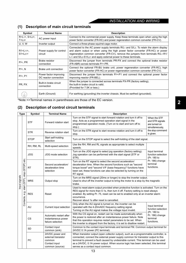
(1) Description of main circuit terminals
*Note:<>Terminal names in parentheses are those of the EC version.
(2) Description of control circuit terminals
Symbol Terminal Name DescriptionR<L1>, S<L2>, T<L3> AC power input Connect to the commercial power supply. Keep these terminals open when using the high
power factor converter (FR-HC) and power regeneration common converter (FR-CV).U, V, W Inverter output Connect a three-phase squirrel-cage motor.
R1<L11>, S1<L21>
Power supply for control circuit
Connected to the AC power supply terminals R/L1 and S/L2. To retain the alarm displayand alarm output or when using the high power factor converter (FR-HC) or powerregeneration common converter (FR-CV), remove the jumpers from terminals R/L1-R1/L11 and S/L2-S1/L21 and apply external power to these terminals.
P/+, PR Brake resistor connection
Disconnect the jumper from terminals PR-PX and connect the optional brake resistor(FR-ABR) across terminals P/+-PR.
P/+, N Brake unit connection Connect the optional FR-BU brake unit, power regeneration converter (FR-RC), highpower factor converter (FR-HC) or power regeneration common converter (FR-CV).
P/+, P1 Power factor improving DC reactor connection
Disconnect the jumper from terminals P/+-P1 and connect the optional power factorimproving reactor (FR-BEL).
PR, PX Built-in brake circuit connection
When the jumper is connected across terminals PX-PR (factory setting), the built-in brake circuit is valid.(Provided for 7.5K or less.)
Earth (Ground) For earthing (grounding) the inverter chassis. Must be earthed (grounded).
Type Symbol Terminal Name Description
Inpu
t sig
nals
Con
tact
s, e
.g. s
tart
(STF
), st
op (S
TOP
) etc
.
STF Forward rotation start
Turn on the STF signal to start forward rotation and turn it off to stop. Acts as a programmed operation start signal in the programmed operation mode. (Turn on to start and turn off to stop.)
When the STF and STR signals are turned on simultaneously, the stop command is given.STR Reverse rotation start Turn on the STR signal to start reverse rotation and turn it off to
stop.
STOP Start self-holding selection Turn on the STOP signal to select the self-holding of the start signal.
RH, RM, RL Multi-speed selection Use the RH, RM and RL signals as appropriate to select multiple speeds.
Input terminal function selection (Pr. 180 to Pr. 186) change terminal functions.
JOG JOG mode selectionTurn on the JOG signal to select jog operation (factory setting). Jog operation can be performed with the start signal (STF or STR).
RTSecond acceleration/deceleration time selection
Turn on the RT signal to select the second acceleration/ deceleration time. When the second functions such as "second torque boost" and "second V/F (base frequency)" functions have been set, these functions can also be selected by turning on the RT signal.
MRS Output stopTurn on the MRS signal (20ms or longer) to stop the inverter output. Used to shut off the inverter output to bring the motor to a stop by the magnetic brake.
RES Reset
Used to reset alarm output provided when protective function is activated. Turn on the RES signal for more than 0.1s, then turn it off. Factory setting is reset always enabled. By setting Pr. 75, reset can be set to enabled only at an inverter alarm occurrence.Recover about 1s after reset is cancelled.
AU Current input selectionOnly when the AU signal is turned on, the inverter can be operated with the 4-20mADC frequency setting signal.Turning on the AU signal makes the voltage input invalid.
Input terminal function selection (Pr. 180 toPr. 186) change terminal functions.
CSAutomatic restart after instantaneous power failure selection
With the CS signal on, restart can be made automatically when the power is restored after an instantaneous power failure. Note that this operation requires restart parameters to be set. When the inverter is shipped from the factory, it is set to disallow restart.
SD Contact inputcommon (sink)
Common to the contact input terminals and terminal FM. Common output terminal for 24VDC 0.1A power (PC terminal).
PC
24VDC power and external transistor commonContact inputcommon (source)
When transistor output (open collector output), such as a programmable controller, is connected, connect the external power supply common for transistor output to this terminal to prevent a fault caused by undesirable current. This terminal can be used as a 24VDC, 0.1A power output. When source logic has been selected, this terminal serves as a contact input common.
13
INSTALLATION AND WIRING
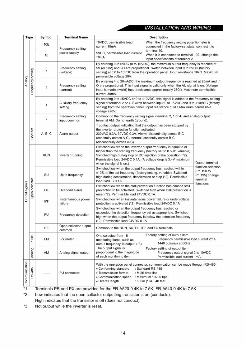
*1: Terminals PR and PX are provided for the FR-A520-0.4K to 7.5K, FR-A540-0.4K to 7.5K.*2: Low indicates that the open collector outputting transistor is on (conducts).
High indicates that the transistor is off (does not conduct).*3: Not output while the inverter is reset.
Type Symbol Terminal Name Description
Ana
log
Freq
uenc
y se
tting
10EFrequency setting power supply
10VDC, permissible load current 10mA
When the frequency setting potentiometer is connected in the factory-set state, connect it to terminal 10.When it is connected to terminal 10E, change the input specifications of terminal 2.
10 5VDC, permissible load current 10mA
2 Frequency setting (voltage)
By entering 0 to 5VDC (0 to 10VDC), the maximum output frequency is reached at 5V (or 10V) and I/O are proportional. Switch between input 0 to 5VDC (factory setting) and 0 to 10VDC from the operation panel. Input resistance 10kΩ. Maximum permissible voltage 20V.
4 Frequency setting (current)
By entering 4 to 20mADC, the maximum output frequency is reached at 20mA and I/O are proportional. This input signal is valid only when the AU signal is on. (Voltage input is made invalid) Input resistance approximately 250Ω. Maximum permissible current 30mA.
1 Auxiliary frequency setting
By entering 0 to ±5VDC or 0 to ±10VDC, this signal is added to the frequency setting signal of terminal 2 or 4. Switch between input 0 to ±5VDC and 0 to ±10VDC (factory setting) from the operation panel. Input resistance 10kΩ. Maximum permissible voltage ±20V.
5 Frequency setting input common
Common to the frequency setting signal (terminal 2, 1 or 4) and analog output terminal AM. Do not earth (ground).
Out
put s
igna
ls
Con
tact
A, B, C Alarm output
1 contact output indicating that the output has been stopped by the inverter protective function activated.230VAC 0.3A, 30VDC 0.3A. Alarm: discontinuity across B-C (continuity across A-C), normal: continuity across B-C (discontinuity across A-C).
Output terminal function selection (Pr. 190 to Pr. 195) change terminal functions.
Ope
n co
llect
or
RUN Inverter running
Switched low when the inverter output frequency is equal to or higher than the starting frequency (factory set to 0.5Hz, variable). Switched high during stop or DC injection brake operation (*2). Permissible load 24VDC 0.1A. (A voltage drop is 3.4V maximum when the signal is on.)
SU Up to frequency
Switched low when the output frequency has reached within ±10% of the set frequency (factory setting, variable). Switched high during acceleration, deceleration or stop (*2). Permissible load 24VDC 0.1A.
OL Overload alarmSwitched low when the stall prevention function has caused stall prevention to be activated. Switched high when stall prevention is reset (*2). Permissible load 24VDC 0.1A.
IPF Instantaneous power failure
Switched low when instantaneous power failure or undervoltage protection is activated (*2). Permissible load 24VDC 0.1A.
FU Frequency detection
Switched low when the output frequency has reached or exceeded the detection frequency set as appropriate. Switched high when the output frequency is below the detection frequency (*2). Permissible load 24VDC 0.1A
SE Open collector output common Common to the RUN, SU, OL, IPF and FU terminals.
Pul
se FM For meterOne selected from 16 monitoring items, such as output frequency, is output. (*3) The output signal is proportional to the magnitude of each monitoring item.
Factory setting of output item:Frequency permissible load current 2mA1440 pulses/s at 60Hz
Ana
log
AM Analog signal outputFactory setting of output item:
Frequency output signal 0 to 10VDCPermissible load current 1mA
Com
mun
icat
ion
RS
-485
PU connector
With the operation panel connector, communication can be made through RS-485.• Conforming standard : Standard RS-485• Transmission format : Multi-drop link• Communication speed : Maximum 19200 bps• Overall length : 500m (1640.40 feet.)
14

INSTALLATION AND WIRING
2
2.2.2 Wiring of the main circuit
(1) Wiring instructions
1) Crimping terminals with insulation sleeves are recommended for use with the power and motor cables.2) Cut the protective bushes of the wiring cover when running the cables. (22K or less)3) Power must not be applied to the output terminals (U, V, W) of the inverter. Otherwise the inverter will be
damaged.4) After wiring, wire off-cuts must not be left in the inverter.
Wire off-cuts can cause an alarm, failure or malfunction. Always keep the inverter clean.When drilling mounting holes in a control box etc., exercise care to prevent chips and other foreignmatter from entering the inverter.
5) Use cables of the recommended size for wiring to make the voltage drop 2% or less.If the wiring distance is long between the inverter and motor, a main circuit cable voltage drop will causethe motor torque to decrease especially at the output of a low frequency. (A selection example for thewiring length of 20m (65.62 feet) is shown on page 19.)
6) The overall wiring length should be 500m (1640.40 feet) maximum.Especially for long distance wiring, the overcurrent protection may be misactivated or the devicesconnected to the output side may misoperate or become faulty under the influence of a charging currentdue to the stray capacitance of the wiring. Therefore, the maximum overall wiring length should be asindicated in the following table. (When two or more motors are connected to the inverter, the total wiringlength should be within the indicated value.)
7) Connect only the recommended optional brake resistor between the terminals P and PR <+ and PR>.These terminals must not be shorted.
8) Electromagnetic wave interferenceThe input/output (main circuit) of the inverter includes high frequency, which may interfere with thecommunication devices (such as AM radios) used near the inverter. In this case, install the FR-BIFoptional radio noise filter (for use on the input side only) or FR-BSF01 or FR-BLF line noise filter tominimize interference.
Inverter Capacity 0.4K 0.75K 1.5K or moreNon-low acoustic noise mode 300m (984.24 feet) 500m (1640.40 feet) 500m (1640.40 feet)Low acoustic noise mode 200m (656.16 feet) 300m (984.24 feet) 500m (1640.40 feet)
Overall wiring length (1.5K or more)
300m (984.24 feet) + 300m (984.24 feet) = 600m (1968.48 feet)
500m (1640.40 feet) maximum
300m (984.24 feet)
300m (984.24 feet)
15

INSTALLATION AND WIRING
9) Do not install a power capacitor, surge suppressor or radio noise filter (FR-BIF option) on the output sideof the inverter.This will cause the inverter to trip or the capacitor and surge suppressor to be damaged. If any of theabove devices are installed, immediately remove them. (If the FR-BIF radio noise filter is connected,switching power off during motor operation may result in E.UVT. In this case, connect the radio noisefilter on the primary side of the electromagnetic contactor.)
10) When rewiring after operation, make sure that the POWER lamp has gone off, and when more than 10minutes have elapsed after power-off, check with a meter that the voltage is zero. After that, startrewiring work. For some time after power-off, there is a dangerous voltage in the capacitor.
11) Use the space on the left-hand side of the main circuit terminal block to wire the cables for connection ofthe control circuit power supply terminals R1, S1 <L11, L21> of the FR-A520-11K.
CAUTION
Do not use residual current protective device as the only protection against indirect contact.Protective earth (ground) connection essential.
Do not connect more than 2 wires on the protective earth (ground) terminal.
Use contactor and no fuse breaker EN/IEC standard compliant.
Use transformer or surge absorber EN/IEC standard compliant.
Notes on Earthing (Grounding)
• Leakage currents flow in the inverter. To prevent an electric shock, the inverter and motor must beearthed (grounded). Earthing (grounding) must conform to the requirements of national and local safetyregulations and electrical code. (JIS, NEC section 250, IEC 536 class 1 and other applicable standards)
• Use the dedicated earth (ground) terminal to earth (ground) the inverter. (Do not use the screw in thecase, chassis, etc.)
• Use the thickest possible earth (ground) cable.Usethe cable whose size is equal to or greater thanthat indicated below, and minimize the cablelength. The earthing (grounding) point should beas near as possible to the inverter.
• Earth (Ground) the motor on the inverter sideusing one wire of the 4-core cable.
(Unit: mm2)
Motor CapacityEarth (Ground) Cable Gauge
200V class 400V class2.2kW (3HP) or less 2 23.7kW (5HP) 3.5 25.5kW, 7.5kW (7.5HP, 10HP) 5.5 3.511kW to 15kW (15 to 20HP) 14 818.5kW to 37kW (25 to 50HP) 22 1445kW, 55kW (60, 75HP) 38 22
U V W
P1
Screw size (M5)
Connection cable
Charge lamp
R1 S1
T⟨L3⟩
R⟨L1⟩
S⟨L2⟩
⟨L11⟩ ⟨L21⟩
N⟨−⟩
P⟨+⟩
16
INSTALLATION AND WIRING
2
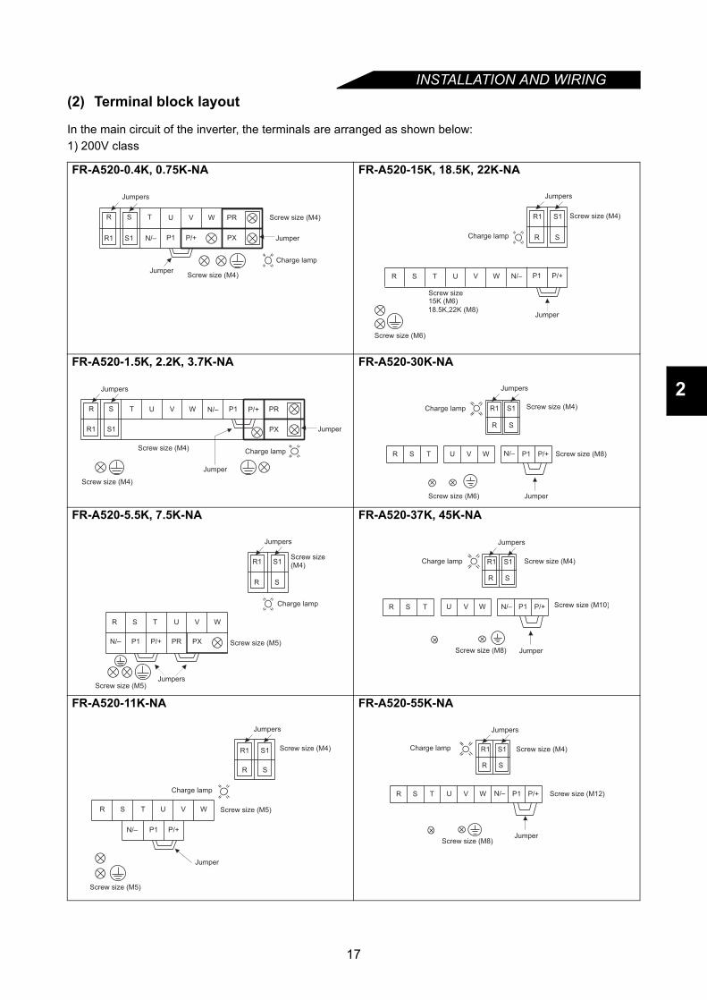
(2) Terminal block layout
In the main circuit of the inverter, the terminals are arranged as shown below:1) 200V class
FR-A520-0.4K, 0.75K-NA FR-A520-15K, 18.5K, 22K-NA
FR-A520-1.5K, 2.2K, 3.7K-NA FR-A520-30K-NA
FR-A520-5.5K, 7.5K-NA FR-A520-37K, 45K-NA
FR-A520-11K-NA FR-A520-55K-NA
U V W PR
P1
Screw size (M4)
PX
Jumper
Screw size (M4)
Charge lamp
N/– P/+
R
R1
S T
S1
Jumpers
Jumper
15K (M6)
18.5K,22K (M8)
R
R1
S
R S
T
S1
U V W
Charge lamp
Screw size
Screw size (M6)
Screw size (M4)
Jumper
P1N/– P/+
Jumpers
U V W PRP1
PX
Screw size (M4)
Jumper
Screw size (M4)Charge lamp
N/– P/+R
R1
S T
S1 Jumper
Jumpers
R S T U V W
R1 S1
N/– P1 P/+
R S
Charge lamp Screw size (M4)
Screw size (M8)
Screw size (M6) Jumper
Jumpers
N/– P/+
U V W
P1 PR PX
Charge lamp
Screw size (M5)
Screw size (M5)
Screw size(M4)
Jumpers
R
R1
S
R S
T
S1
Jumpers
N/– P/+U V W P1
Charge lamp Screw size (M4)
Screw size (M10)
Screw size (M8) Jumper
R
R1
S
R S
T
S1
Jumpers
N/– P/+P1
Jumper
R
R1
S
R S
T
S1
U V W
Screw size (M4)
Charge lamp
Screw size (M5)
Screw size (M5)
Jumpers
N/– P/+U V W P1
Charge lamp Screw size (M4)
Screw size (M12)
Screw size (M8)Jumper
R
R1
S
R S
T
S1
Jumpers
17

INSTALLATION AND WIRING
2) 400V class
Note: Terminal names in parenthesis are those of the EC version.
FR-A540-0.4K, 0.75K, 1.5K, 2.2K, 3.7K-NA/-EC FR-A540-30K-NA/-EC
FR-A540-5.5K, 7.5K-NA/-EC FR-A540-37K, 45K, 55K-NA/-EC
FR-A540-11K, 15K, 18.5K, 22K-NA/-EC
U V W PR
PX
Screw size (M4)
Screw size (M4)
Jumper
Charge lamp
P1N/– P/+
Jumper
Jumpers
R<L1>
S<L2>
T<L3>
R1<L11>
S1<L21>
<L21><L11>
<L2><L1>
SR<L1> <L2> <L3>
T
R S
R1 S1
Jumpers
U V W P1
Jumper
Screw size (M4)
Screw size (M6)
Screw size (M6)
Charge lamp
N/– P/+
Screw size (M4)
R<L1>
S<L2>
T<L3>
R<L1>
S<L2>
R1<L11>
S1<L21>
Jumpers
U V W
P1 PR PX
Screw size (M4)
Charge lamp
Screw size (M4)
Jumpers
N/– P/+
SR T
R S
R1 S1
<L1>
<L1> <L2>
<L11> <L21>
<L2> <L3>
Jumpers
U V W P1
Jumper
Screw size (M4)
Screw size (M8)
Screw size (M8)
Charge lamp
N/– P/+
SL2
R
<L1> < > < >TL3
RL1
SL2
R1L11
S1L21< >
< >
< >
< >
U V W P1
Jumper
Screw size (M4)
Charge lamp
Screw size (M6)
Screw size (M6)
N/– P/+
Jumpers
18
INSTALLATION AND WIRING
2
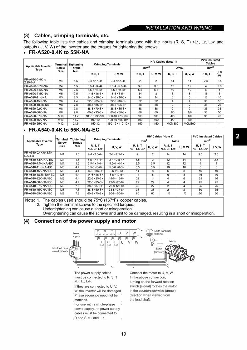
(3) Cables, crimping terminals, etc.The following table lists the cables and crimping terminals used with the inputs (R, S, T) <L1, L2, L3> andoutputs (U, V, W) of the inverter and the torques for tightening the screws:• FR-A520-0.4K to 55K-NA
• FR-A540-0.4K to 55K-NA/-EC
(4) Connection of the power supply and motor
Applicable InverterType
Terminal Screw Size
TighteningTorque
N⋅m
Crimping TerminalsHIV Cables (Note 1) PVC insulated
Cablesmm2 AWG mm2
R, S, T U, V, W R, S, T U, V, W R, S, T U, V, W R, S, T U, V, W
FR-A520-0.4K to 2.2K-NA M4 1.5 2-4 <2.5-4> 2-4 <2.5-4> 2 2 14 14 2.5 2.5
FR-A520-3.7K-NA M4 1.5 5.5-4 <4-4> 5.5-4 <2.5-4> 3.5 3.5 12 12 4 2.5FR-A520-5.5K-NA M5 2.5 5.5-5 <6-5> 5.5-5 <4-5> 5.5 5.5 10 10 6 4FR-A520-7.5K-NA M5 2.5 14-5 <16-5> 8-5 <6-5> 14 8 6 8 16 6FR-A520-11K-NA M5 2.5 14-5 <16-5> 14-5 <16-5> 14 14 6 6 16 10FR-A520-15K-NA M6 4.4 22-6 <35-6> 22-6 <16-6> 22 22 4 4 35 16FR-A520-18.5K-NA M8 7.8 38-8 <35-8> 38-8 <25-8> 38 38 2 2 35 25FR-A520-22K-NA M8 7.8 38-8 <70-8> 38-8 <35-8> 38 38 2 2 35 35FR-A520-30K-NA M8 7.8 60-8 <95-8> 60-8 <30-8> 60 60 1/0 1/0 50 50FR-A520-37K-NA M10 14.7 100-10 <95-10> 100-10 <70-10> 100 100 4/0 4/0 95 70FR-A520-45K-NA M10 14.7 100-10 100-10 <95-10> 100 100 4/0 4/0 - -FR-A520-55K-NA M12 24.5 150-12 150-12 <110-12> 150 150 MCM300 MCM300 - -
Applicable InverterType
Terminal Screw Size
TighteningTorque
N⋅m
Crimping TerminalsHIV Cables (Note 1) PVC insulated Cables
mm2 AWG mm2
R, S, T<L1, L2, L3> U, V, W R, S, T
<L1, L2, L3> U, V, W R, S, T<L1, L2, L3> U, V, W R, S, T
<L1, L2, L3> U, V, W
FR-A540-0.4K to 3.7K-NA/-EC M4 1.5 2-4 <2.5-4> 2-4 <2.5-4> 2 2 14 14 2.5 2.5
FR-A540-5.5K-NA/-EC M4 1.5 5.5-4 <4-4> 2-4 <2.5-4> 3.5 2 12 14 4 2.5FR-A540-7.5K-NA/-EC M4 1.5 5.5-4 <4-4> 5.5-4 <4-4> 3.5 3.5 12 12 4 4FR-A540-11K-NA/-EC M6 4.4 5.5-6 <6-6> 5.5-6 <6-6> 5.5 5.5 10 10 6 6FR-A540-15K-NA/-EC M6 4.4 14-6 <16-6> 8-6 <10-6> 14 8 6 8 16 10FR-A540-18.5K-NA/-EC M6 4.4 14-6 <16-6> 8-6 <10-6> 14 8 6 8 16 10FR-A540-22K-NA/-EC M6 4.4 22-6 <25-6> 14-6 <16-6> 22 14 4 6 25 16FR-A540-30K-NA/-EC M6 4.4 22-6 <25-6> 22-6 <25-6> 22 22 4 4 25 25FR-A540-37K-NA/-EC M8 7.8 38-8 <37-8> 22-8 <25-8> 38 22 2 4 35 25FR-A540-45K-NA/-EC M8 7.8 38-8 <50-8> 38-8 <37-8> 38 38 2 2 50 35FR-A540-55K-NA/-EC M8 7.8 60-8 <70-8> 60-8 <50-8> 60 60 1/0 1/0 50 50
Note: 1. The cables used should be 75°C (167°F) copper cables.2. Tighten the terminal screws to the specified torques.
Undertightening can cause a short or misoperation.Overtightening can cause the screws and unit to be damaged, resulting in a short or misoperation.
Earth
(Ground)
Earth (Ground)terminalPower
supply
Motor
Moulded case circuit breaker
Connect the motor to U, V, W.
In the above connection,
turning on the forward rotation
switch (signal) rotates the motor
in the counterclockwise (arrow)
direction when viewed from
the load shaft.
U V W
U V W
R<L1>
S T
R S T
The power supply cables
must be connected to R, S, T
<L1, L2, L3>.
If they are connected to U, V,
W, the inverter will be damaged.
Phase sequence need not be
matched.
For use with a single-phase
power supply,the power supply
cables must be connected to
R and S <L1 and L2>.
<L1>
<L2> <L3>
<L2> <L3>
19
INSTALLATION AND WIRING
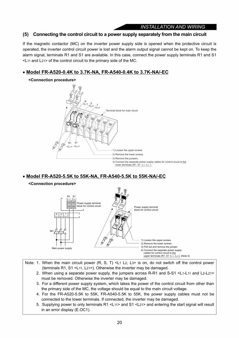
(5) Connecting the control circuit to a power supply separately from the main circuitIf the magnetic contactor (MC) on the inverter power supply side is opened when the protective circuit isoperated, the inverter control circuit power is lost and the alarm output signal cannot be kept on. To keep thealarm signal, terminals R1 and S1 are available. In this case, connect the power supply terminals R1 and S1<L11 and L21> of the control circuit to the primary side of the MC.
• Model FR-A520-0.4K to 3.7K-NA, FR-A540-0.4K to 3.7K-NA/-EC<Connection procedure>
• Model FR-A520-5.5K to 55K-NA, FR-A540-5.5K to 55K-NA/-EC<Connection procedure>
Note: 1. When the main circuit power (R, S, T) <L1 L2, L3> is on, do not switch off the control power(terminals R1, S1 <L11, L21>). Otherwise the inverter may be damaged.
2. When using a separate power supply, the jumpers across R-R1 and S-S1 <L1-L11 and L2-L21>must be removed. Otherwise the inverter may be damaged.
3. For a different power supply system, which takes the power of the control circuit from other thanthe primary side of the MC, the voltage should be equal to the main circuit voltage.
4. For the FR-A520-5.5K to 55K, FR-A540-5.5K to 55K, the power supply cables must not beconnected to the lower terminals. If connected, the inverter may be damaged.
5. Supplying power to only terminals R1 <L11> and S1 <L21> and entering the start signal will resultin an error display (E.OC1).
Terminal block for main circuit
1) Loosen the upper screws
2) Remove the lower screws.
3) Remove the jumpers.
R <L1> S
<L2> T <L3>
R1
<L11>
S1
<L21>
4) Connect the separate power supply cables for control circuit to the
lower terminals (R1, S1 L11, L21 ).
MC
Power supply terminal block for control circuit
Main power supply
Power supply terminalblock for control circuit
R⟨L1⟩
S⟨L2⟩
T⟨L3⟩
R1⟨L11⟩
S1⟨L21⟩
1) Loosen the upper screws.2) Remove the lower screws.3) Pull out and remove the jumper.4) Connect the separate power supply cables for control circuit to the upper terminals (R1, S1 ⟨L11, L21⟩). (Note 4)
20

INSTALLATION AND WIRING
2
2.2.3 Wiring of the control circuit
(1) Wiring instructions
1) Terminals SD, SE and 5 are common to the I/O signals and isolated from each other. Do not earth(ground) these terminals. Avoid connecting the terminals SD and 5 and the terminals SE and 5.
2) Use shielded or twisted cables for connection to the control circuit terminals and run them away from themain and power circuits (including the 200V relay sequence circuit).
3) Since the control circuit input signals are micro currents, use two or more parallel micro signal contacts ora twin contact to prevent a contact fault.
4) It is recommended to use the cables of 0.75mm2 gauge for connection to the control circuit terminals.If the cable gauge used is 1.25mm2 or more, the front cover may be lifted when there are many cablesrunning or the cables are run improperly, resulting in an operation panel or parameter unit contact fault.
(2) Terminal block layout
• NA versionIn the control circuit of the inverter, the terminals are arranged as shown below:Terminal screw size: M3.5Tightening torque: 1.2N⋅m
•EC versionTerminal screw size: M3Tightening torque: 1.2N⋅m
<Wiring procedure>1) For the wiring of the control circuit, strip the sheaths of the cables and use them as they are.
Strip the sheath to the following dimension. A too long stripping dimension may cause a short circuit withthe neighboring cable. A too short dimension may cause cable disconnection.
2) Loosen the terminal screw and insert the cable into the terminal.3) Tighten the screw to the specified torque.
Undertightening can cause cable disconnection or malfunction. Overtightening can cause a short circuit ormalfunction due to the screw or unit damaged.
Note: Wire the stripped cable by twisting it to prevent it from becoming loose. (Do not plate the cable withsolder.)
Note: 1. Use a MCCB (Moulded case circuit breaker) or fuse on the inverter input (primary) side.2. Make sure that the control circuit terminal wiring does not touch power circuit terminals (or
screws) or conducting power circuit.
A
RL
SE RUN SU IPF OL FU SD STF STR JOG CS
RM RH RT AU STOP MRS RES SD FM
B C PC AM 10E 10 2 5 4 1
A
SE RUN SU LPF OL STOP MRS RES PC STF
B C SD AM 10E 10 2 5 4 1 RL RM RH RT AU
STR JOG CS FM SDFU
6mm ± 1mm
21

INSTALLATION AND WIRING
(3) Changing the control logicThe input signals are set to sink logic for the NA version, and to source Logic for the EC version.To change the control logic, the jumper connector on the back of the control circuit terminal block must bemoved to the other position.(The output signals may be used in either the sink or source logic independently of the jumper connectorposition.)1) Loosen the two installation screws in both ends of the control circuit terminal block. (The screws cannot be
removed.)Pull down the terminal block from the back of the control circuit terminals.
2) Remove the jumper connector in the sink logic position on the back surface of the control circuit terminalblock and fit it in the source logic position.
3) Using care not to bend the pins of the control circuit connector, reinstall the control circuit terminal blockand fix it with the installation screws.
Note: 1. Make sure that the control circuit connector is fitted correctly.2. While power is on, never disconnect the control circuit terminal block.3. The sink-source logic change-over jumper connector must be fitted in only one of those positions.
If it is fitted in both positions at the same time, the inverter may be damaged.
CON1
SIN
KC
ON
3
CO
N2
SOU
RC
E
SINK
CO
N3
CO
N2
SOU
RC
E
SOU
RC
E
CO
N3
CO
N2
SINK
EC version NA version
22
INSTALLATION AND WIRING
2
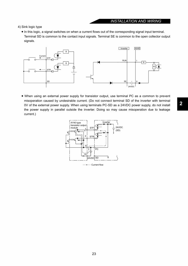
4) Sink logic type• In this logic, a signal switches on when a current flows out of the corresponding signal input terminal.
Terminal SD is common to the contact input signals. Terminal SE is common to the open collector outputsignals.
• When using an external power supply for transistor output, use terminal PC as a common to preventmisoperation caused by undesirable current. (Do not connect terminal SD of the inverter with terminal0V of the external power supply. When using terminals PC-SD as a 24VDC power supply, do not installthe power supply in parallel outside the inverter. Doing so may cause misoperation due to leakagecurrent.)
AX40Inverter
R
R
RUN
SE
1
9
24VDC
R
STF
STR
SD
Current
R
9
10
24VDC SD
PC
24VDC(SD)
AY40 type transistor output module
Inverter
1
2 STR
STF
Current flow
23
INSTALLATION AND WIRING
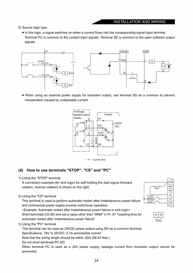
5) Source logic type• In this logic, a signal switches on when a current flows into the corresponding signal input terminal.Terminal PC is common to the contact input signals. Terminal SE is common to the open collector outputsignals.
• When using an external power supply for transistor output, use terminal SD as a common to preventmisoperation caused by undesirable current.
(4) How to use terminals "STOP", "CS" and "PC"
3) Using the "PC" terminalThis terminal can be used as 24VDC power output using SD as a common terminal.Specifications: 18V to 26VDC, 0.1A permissible currentNote that the wiring length should be within 30m (98.43 feet.).Do not short terminals PC-SD.When terminal PC is used as a 24V power supply, leakage current from transistor output cannot beprevented.
1) Using the "STOP" terminalA connection example (for sink logic) for self-holding the start signal (forward rotation, reverse rotation) is shown on the right.
2) Using the "CS" terminalThis terminal is used to perform automatic restart after instantaneous power failure and commercial power supply-inverter switchover operation.<Example: Automatic restart after instantaneous power failure in sink logic>Short terminals CS-SD and set a value other than "9999" in Pr. 57 "coasting time for automatic restart after instantaneous power failure".
AX80
24VDC
RUN
SE
1
9
R
Inverter
R
PC
STF
STRR
R
Current
AY-80 typetransistor outputmodule. 9
1
2
10
PC
STF
STR
SD
24VDC(SD)
24V
DC
Inverter
Current flow
MRS
RES
SD
STF
STR
STOP
Reverserotation
Stop
Forwardrotation
CS SD
(Short)
24
INSTALLATION AND WIRING
2
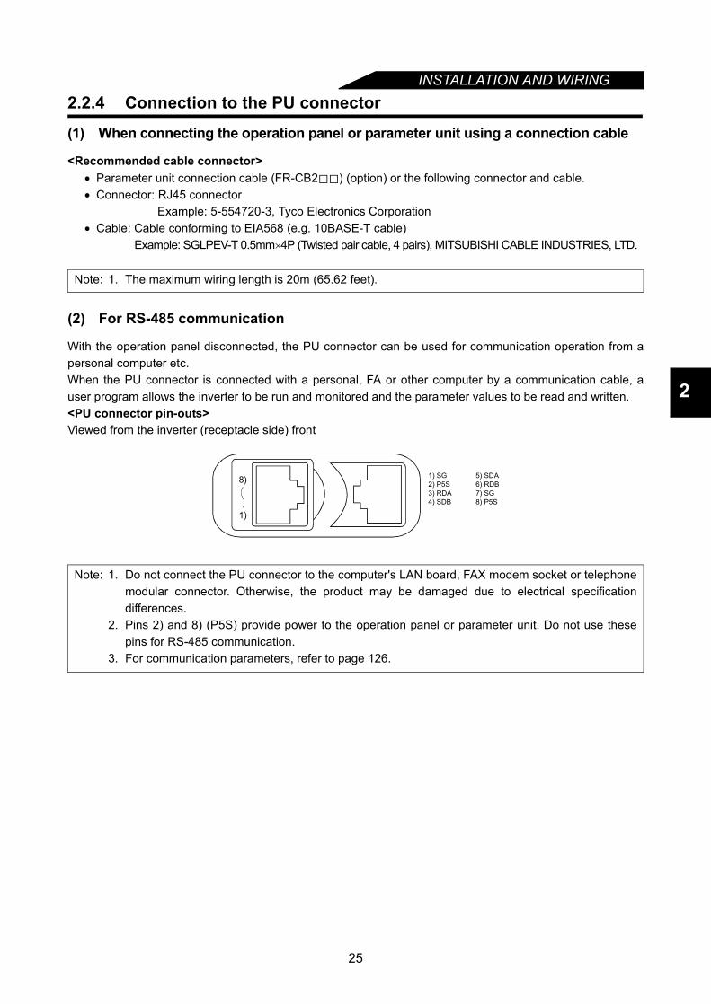
2.2.4 Connection to the PU connector
(1) When connecting the operation panel or parameter unit using a connection cable
<Recommended cable connector>• Parameter unit connection cable (FR-CB2 ) (option) or the following connector and cable.• Connector: RJ45 connector
Example: 5-554720-3, Tyco Electronics Corporation• Cable: Cable conforming to EIA568 (e.g. 10BASE-T cable)
Example: SGLPEV-T 0.5mm×4P (Twisted pair cable, 4 pairs), MITSUBISHI CABLE INDUSTRIES, LTD.
(2) For RS-485 communication
With the operation panel disconnected, the PU connector can be used for communication operation from apersonal computer etc.When the PU connector is connected with a personal, FA or other computer by a communication cable, auser program allows the inverter to be run and monitored and the parameter values to be read and written.<PU connector pin-outs>Viewed from the inverter (receptacle side) front
Note: 1. The maximum wiring length is 20m (65.62 feet).
Note: 1. Do not connect the PU connector to the computer's LAN board, FAX modem socket or telephonemodular connector. Otherwise, the product may be damaged due to electrical specificationdifferences.
2. Pins 2) and 8) (P5S) provide power to the operation panel or parameter unit. Do not use thesepins for RS-485 communication.
3. For communication parameters, refer to page 126.
1) SG2) P5S3) RDA4) SDB
5) SDA6) RDB7) SG8) P5S
1)
8)
25

INSTALLATION AND WIRING
<System configuration example>1) Connection of a computer to the inverter (1:1 connection)
Computer-inverter connection cableFor a connection cable between the computer having RS-232C and the inverter (RS-232C⇔RS-485converter), refer to the table below. Example of product available on the market (as of Apr., 2004)
*The converter cable cannot connect two or more inverters (the computer and inverter are connected on a1:1 basis). Since the product is packed with the RS-232C cable and RS-485 cable (10BASE-T + RJ-45connector), the cable and connector need not be prepared separately. Contact a maker for details of theproduct.
2) Connection of a computer to multiple inverters (1:n connection)
Model MakerFA-T-RS40 * Mitsubishi Electric Engineering Co., Ltd.
REMARKS Refer to the following when fabricating the cable on the user side.
Example of product available on the market (as of Apr., 2004)
REMARKSRefer to the following when fabricating the cable on the user side.Example of product available on the market (as of Apr., 2004)
RS-485 connector
InverterStation 0Computer
RS-485interface/terminal
10BASE-T cable 1)RJ-45 connector 2)
RS-485connector
InverterStation 0Computer
10BASE-T cable 1)
RJ-45 connector 2)
RS-232Ccable
RS-232Cconnector
RS-232C RS-485converter
Max. 15m(49.21 feet)
Product Model Maker
1) 10BASE-T cable SGLPEV-T 0.5mm × 4P* Do not use No. 2 and No. 8 pin (P5S). Mitsubishi Cable Industries, Ltd.
2) RJ-45 connector 5-554720-3 Tyco Electronics Corporation
Max. 15m(49.21 feet)
Computer
RS-232Cconnector
RS-232C cable
Converter
Inverter
Station 0Computer
Termination resistor
RS-485connector
10BASE-T cable 1)
RS-485interface/terminal
RJ-45 connector 2)
Station 1
Station n
(Max. 32 inverters)
Inverter
Station 1
RS-485connector
Inverter
Station 2
Inverter
Station n
10BASE-T cable 1) RJ-45 connector 2)
Inverter
RS-485connector
Inverter
RS-485connector
RS-485connector
RS-485connector
Termination resistor
Distributor
Distributor
* Do not use No. 2 and No. 8 pin (P5S) of the 10 BASE-T cable.
Product Model Maker1) 10BASE-T cable SGLPEV-T 0.5mm × 4P* Mitsubishi Cable Industries, Ltd.2) RJ-45 connector 5-554720-3 Tyco Electronics Corporation
26

INSTALLATION AND WIRING
2
<Wiring method>1) Wiring of one RS-485 computer and one inverter
2) Wiring of one RS-485 computer and "n" inverters (several inverters)
Note: 1. Make connections in accordance with the instruction manual of the computer used.Fully check the terminal numbers of the computer as they differ between models.
2. There may be the influence of reflection depending on the transmission speed and/ortransmission distance. If this reflection hinders communication, provide a terminal resistor. If thePU connector is used to make a connection, use a distributor as a terminal resistor cannot befitted. Connect the terminal resistor only to the inverter remotest from the computer. (Terminalresistor: 100Ω)
Computer Side Terminals
Signal name Description
RDA
RDB
SDA
SDB
RSA
RSB
CSA
CSB
SG
FG
Receive data
Receive data
Send data
Send data
Request to send
Request to send
Clear to send
Clear to send
Signal ground
Frame ground
PU connector
SDA
SDB
RDA
RDB
SG
(Note 1)
0.2mm or more2
Cable connection and signal direction
10BASE-T Cable
Inverter
(Note 1)
Computer
RDARDB
SDASDB
RSARSBCSACSB
SGFG Station 1
SG
RD
BR
DA
SDB
SDA
Station 2
SG
RD
BR
DA
SDB
SDA
Station n
SGR
DB
RD
ASD
BSD
A
Inverter Inverter Inverter
Cable connection and signal direction
10BASE-T Cable
Terminationresistor(Note 2)
27
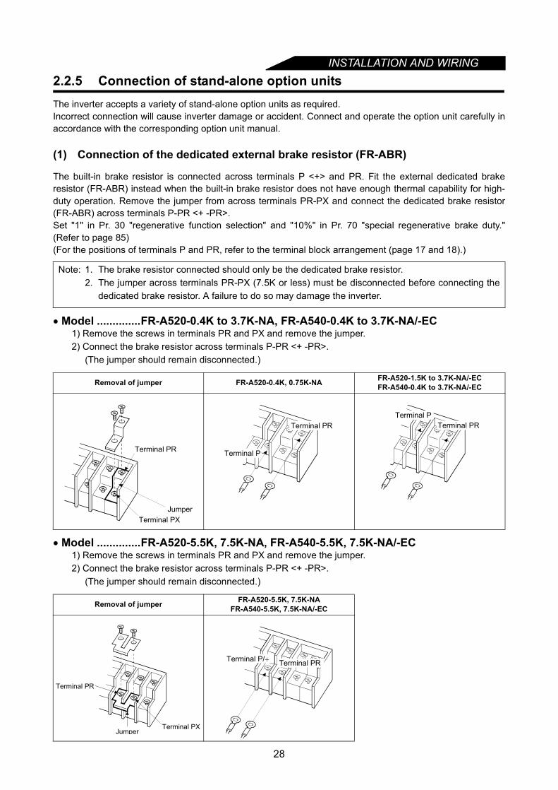
INSTALLATION AND WIRING
2.2.5 Connection of stand-alone option unitsThe inverter accepts a variety of stand-alone option units as required.Incorrect connection will cause inverter damage or accident. Connect and operate the option unit carefully inaccordance with the corresponding option unit manual.(1) Connection of the dedicated external brake resistor (FR-ABR)
The built-in brake resistor is connected across terminals P <+> and PR. Fit the external dedicated brakeresistor (FR-ABR) instead when the built-in brake resistor does not have enough thermal capability for high-duty operation. Remove the jumper from across terminals PR-PX and connect the dedicated brake resistor(FR-ABR) across terminals P-PR <+ -PR>.Set "1" in Pr. 30 "regenerative function selection" and "10%" in Pr. 70 "special regenerative brake duty."(Refer to page 85)(For the positions of terminals P and PR, refer to the terminal block arrangement (page 17 and 18).)
• Model ..............FR-A520-0.4K to 3.7K-NA, FR-A540-0.4K to 3.7K-NA/-EC1) Remove the screws in terminals PR and PX and remove the jumper.2) Connect the brake resistor across terminals P-PR <+ -PR>.
(The jumper should remain disconnected.)
• Model ..............FR-A520-5.5K, 7.5K-NA, FR-A540-5.5K, 7.5K-NA/-EC1) Remove the screws in terminals PR and PX and remove the jumper.2) Connect the brake resistor across terminals P-PR <+ -PR>.
(The jumper should remain disconnected.)
Note: 1. The brake resistor connected should only be the dedicated brake resistor.2. The jumper across terminals PR-PX (7.5K or less) must be disconnected before connecting the
dedicated brake resistor. A failure to do so may damage the inverter.
Removal of jumper FR-A520-0.4K, 0.75K-NA FR-A520-1.5K to 3.7K-NA/-ECFR-A540-0.4K to 3.7K-NA/-EC
Removal of jumper FR-A520-5.5K, 7.5K-NAFR-A540-5.5K, 7.5K-NA/-EC
Terminal PX
Terminal PR
Jumper
Terminal PR
Terminal P
Terminal PRTerminal P
Jumper
Terminal PR
Terminal PX
Terminal PRTerminal P/+
28

INSTALLATION AND WIRING
2
(2) Connection of the brake unit (FR-BU)
Connect the optional FR-BU brake unit as shown below to improve the braking capability during deceleration.
Note: 1. Connect the inverter terminals (P, N) <+, -> and FR-BU brake unit terminals so that their terminalsignals match with each other. (Incorrect connection will damage the inverter.) For model 7.5K orless, the jumper across terminals PR-PX must be removed.
2. The wiring distance between the inverter, brake unit and resistor unit should be within 5m (16.40feet). If twisted wires are used, the distance should be within 10m (32.81 feet).
3. When the transistor in the brake unit fails, the brake transistor becomes extremely hot and it hasa chance to get fire. Therefore, install a magnetic contactor on the inverter's power supply side toshut off a current in case of failure.
4. When the power supply is 400V class, install a step-down transformer.
MC
U
V
W
P/+
N/–
PR
PX
IM
PR
P/+
N/-
HA
HB
HC
Brake unitFR-BU-(H)
Resistor unitFR-BR-(H)
THS TH2
PPR
ON
MC
OFFMC
Inverter
Motor
T (Note 4)
TH1
Powersupply
R <L1>< >< >
S L2
T L3
Normal : TH1 - TH2....close
Remove jumper. Alarm : TH1 - TH2....open
29
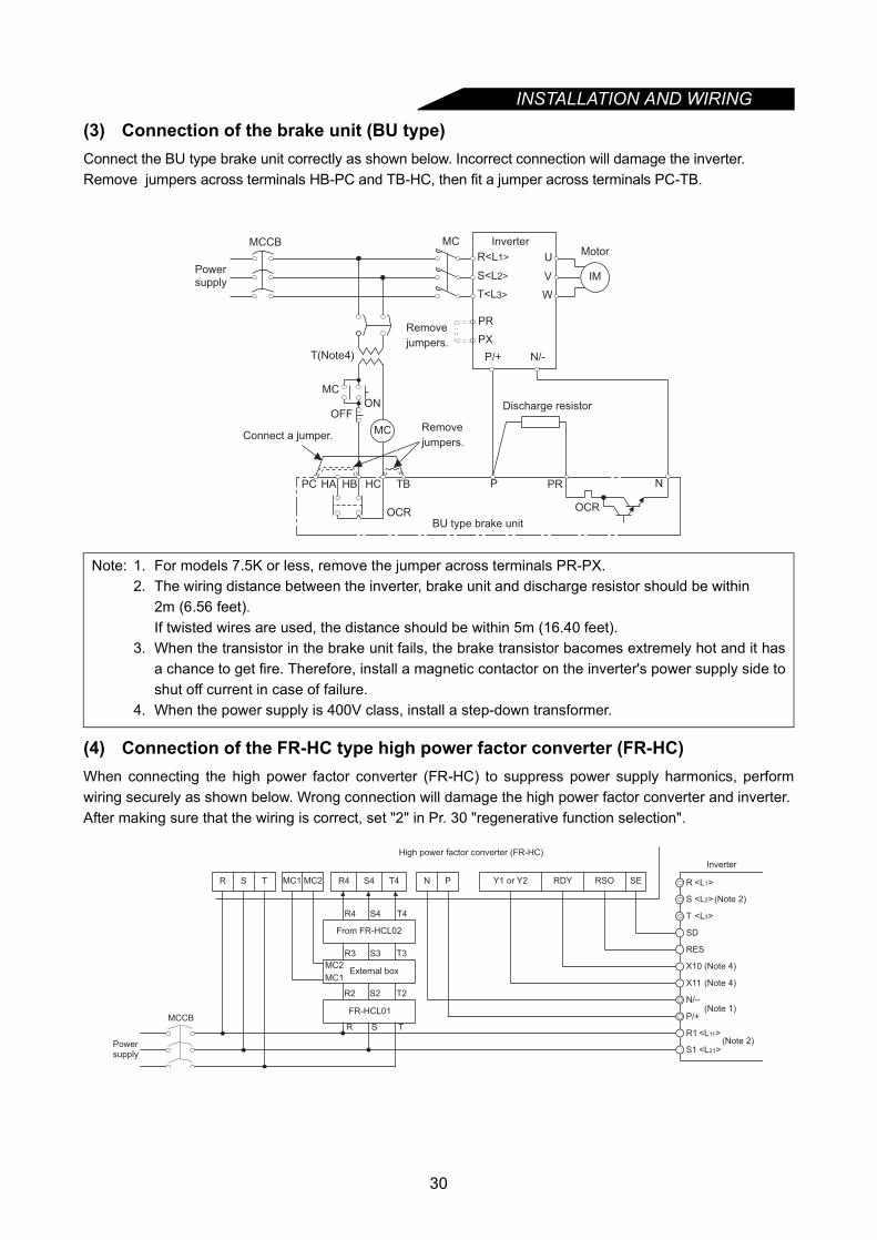
INSTALLATION AND WIRING
(3) Connection of the brake unit (BU type)Connect the BU type brake unit correctly as shown below. Incorrect connection will damage the inverter.Remove jumpers across terminals HB-PC and TB-HC, then fit a jumper across terminals PC-TB.
(4) Connection of the FR-HC type high power factor converter (FR-HC)When connecting the high power factor converter (FR-HC) to suppress power supply harmonics, performwiring securely as shown below. Wrong connection will damage the high power factor converter and inverter.After making sure that the wiring is correct, set "2" in Pr. 30 "regenerative function selection".
Note: 1. For models 7.5K or less, remove the jumper across terminals PR-PX.2. The wiring distance between the inverter, brake unit and discharge resistor should be within
2m (6.56 feet).If twisted wires are used, the distance should be within 5m (16.40 feet).
3. When the transistor in the brake unit fails, the brake transistor bacomes extremely hot and it hasa chance to get fire. Therefore, install a magnetic contactor on the inverter's power supply side toshut off current in case of failure.
4. When the power supply is 400V class, install a step-down transformer.
R<L1>
S<L2>
T<L3>
(Note4)
Remove
jumpers.
PR
PX
MotorInverter
BU type brake unit
T
MC
U
V
W
HCHBHA TB P
OCR
PR
MCCB
PC
ONOFF
MC
OCR
N
MC Remove
jumpers.
IM
Discharge resistor
N/-P/+
Powersupply
Connect a jumper.
R1
S1
T
S (Note 2)
R
(Note 2)
<L2>
<L1>
<L3>
<L11>
<L21>
X10 (Note 4)
X11 (Note 4)
N/–
P/+
RES
SD
Y1 or Y2 RDY RSO SE
Inverter
High power factor converter (FR-HC)
MCCB
R S T R4 S4 T4 N P
From FR-HCL02
Powersupply
MC1 MC2
External boxMC1
MC2
FR-HCL01
R4 S4 T4
R3 S3 T3
R2 S2 T2
R S T
(Note 1)
30
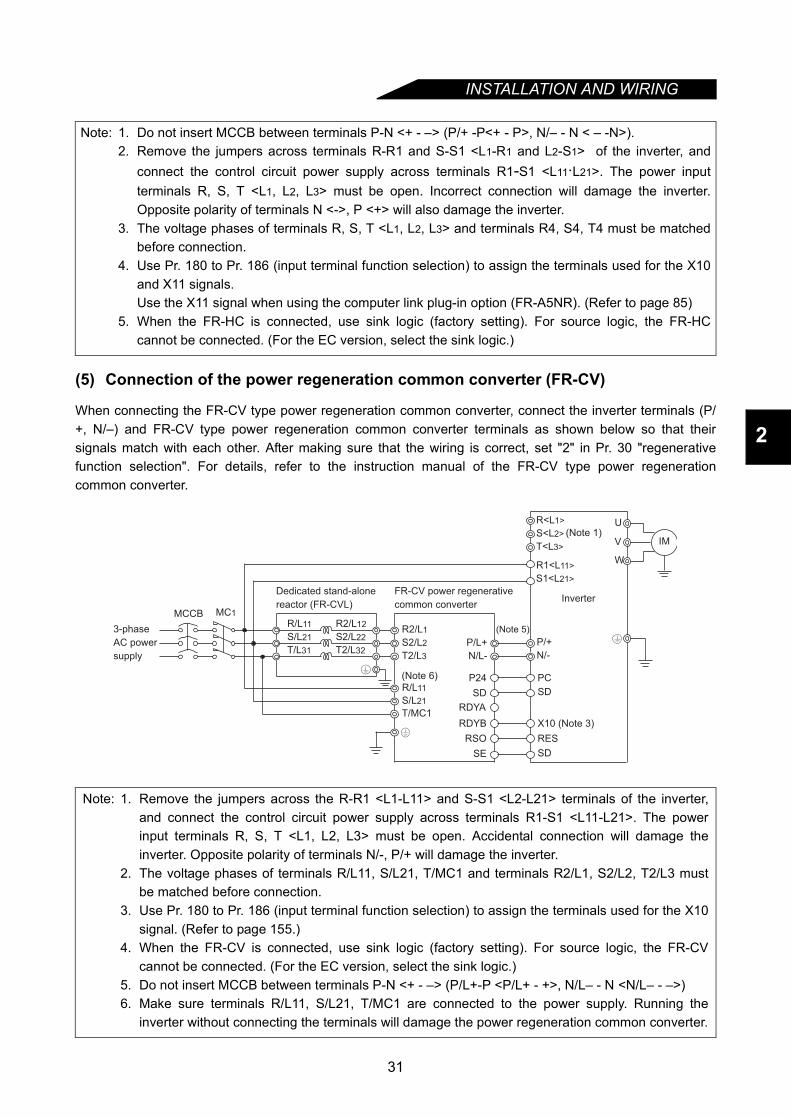
INSTALLATION AND WIRING
2
(5) Connection of the power regeneration common converter (FR-CV)
When connecting the FR-CV type power regeneration common converter, connect the inverter terminals (P/+, N/–) and FR-CV type power regeneration common converter terminals as shown below so that theirsignals match with each other. After making sure that the wiring is correct, set "2" in Pr. 30 "regenerativefunction selection". For details, refer to the instruction manual of the FR-CV type power regenerationcommon converter.
Note: 1. Do not insert MCCB between terminals P-N <+ - –> (P/+ -P<+ - P>, N/– - N < – -N>).2. Remove the jumpers across terminals R-R1 and S-S1 <L1-R1 and L2-S1> of the inverter, and
connect the control circuit power supply across terminals R1-S1 <L11·L21>. The power inputterminals R, S, T <L1, L2, L3> must be open. Incorrect connection will damage the inverter.Opposite polarity of terminals N <->, P <+> will also damage the inverter.
3. The voltage phases of terminals R, S, T <L1, L2, L3> and terminals R4, S4, T4 must be matchedbefore connection.
4. Use Pr. 180 to Pr. 186 (input terminal function selection) to assign the terminals used for the X10and X11 signals.Use the X11 signal when using the computer link plug-in option (FR-A5NR). (Refer to page 85)
5. When the FR-HC is connected, use sink logic (factory setting). For source logic, the FR-HCcannot be connected. (For the EC version, select the sink logic.)
Note: 1. Remove the jumpers across the R-R1 <L1-L11> and S-S1 <L2-L21> terminals of the inverter,and connect the control circuit power supply across terminals R1-S1 <L11-L21>. The powerinput terminals R, S, T <L1, L2, L3> must be open. Accidental connection will damage theinverter. Opposite polarity of terminals N/-, P/+ will damage the inverter.
2. The voltage phases of terminals R/L11, S/L21, T/MC1 and terminals R2/L1, S2/L2, T2/L3 mustbe matched before connection.
3. Use Pr. 180 to Pr. 186 (input terminal function selection) to assign the terminals used for the X10signal. (Refer to page 155.)
4. When the FR-CV is connected, use sink logic (factory setting). For source logic, the FR-CVcannot be connected. (For the EC version, select the sink logic.)
5. Do not insert MCCB between terminals P-N <+ - –> (P/L+-P <P/L+ - +>, N/L– - N <N/L– - –>)6. Make sure terminals R/L11, S/L21, T/MC1 are connected to the power supply. Running the
inverter without connecting the terminals will damage the power regeneration common converter.
MC1MCCBR/L11
Dedicated stand-alone
reactor (FR-CVL)
S/L21
T/L31
R2/L12
S2/L22
T2/L32
R2/L1
S2/L2
T2/L3
R/L11
S/L21
T/MC1
P/L+
N/L-
U
V
W
IM
3-phase
AC power
supply
FR-CV power regenerative
common converterInverter
PC
SD
X10 (Note 3)
RES
P24
SD
RDYB
RSO
SE
RDYA
(Note 6)
(Note 5)
P/+
N/-
R<L1>
S<L2>
T<L3>
R1<L11>
S1<L21>
(Note 1)
SD
31

INSTALLATION AND WIRING
(6) Connection of the power regeneration converter (FR-RC)(For power coordination, always install the power factor improving reactor (FR-BAL).)When connecting the FR-RC type power regeneration converter, connect the inverter terminals (P/+, N/-) and FR-RC type power regeneration converter terminals as shown below so that their signals match with eachother. After making sure that the wiring is correct, set "0" in Pr. 30 "regenerative function selection".For details, refer to the FR-RC type power regeneration converter manual.
(7) Connection of the power factor improving DC reactor (option)
Note: 1. For models 7.5K or less, the jumper across terminals PR-PX must be removed.2. How to connect the FR-BAL power factor improving AC reactor (option)
When using two or more inverters in the same system, small impedance between the inverterswill cause a regenerative current from the power regeneration converter to leak into the otherinverters, resulting in overcurrent alarm of the other inverters. To prevent this, install a powerfactor improving AC reactor on the power supply side for all the inverters.
3. Do not insert MCCB between terminals P-N <+ - –> (P/+ -P/+ <+ - P/+>, N/– - N/– <– - N/->).
Connect the FR-BEL power factor improving DCreactor between terminals P1-P <P1- +>. In thiscase, the jumper connected across terminals P1-P<P1- +> must be removed. Otherwise, the reactorwill not function.
<Connection method>
Note: 1. The wiring distance should be within 5m (16.40 feet).2. The size of the cables used should be equal to or larger than that of the power supply cables
(R, S, T) <L1, L2, L3>.
N/– P/+
MCCB FR-BAL R/L1 S/L2 T/L3
P/+
N/-
FR-RC power regeneration converter
Power supply
Inverter
R<L1> <L2> <L3>
S T
(Note 3)
P1
FR-BEL
Remove the jumper.
P/+
32
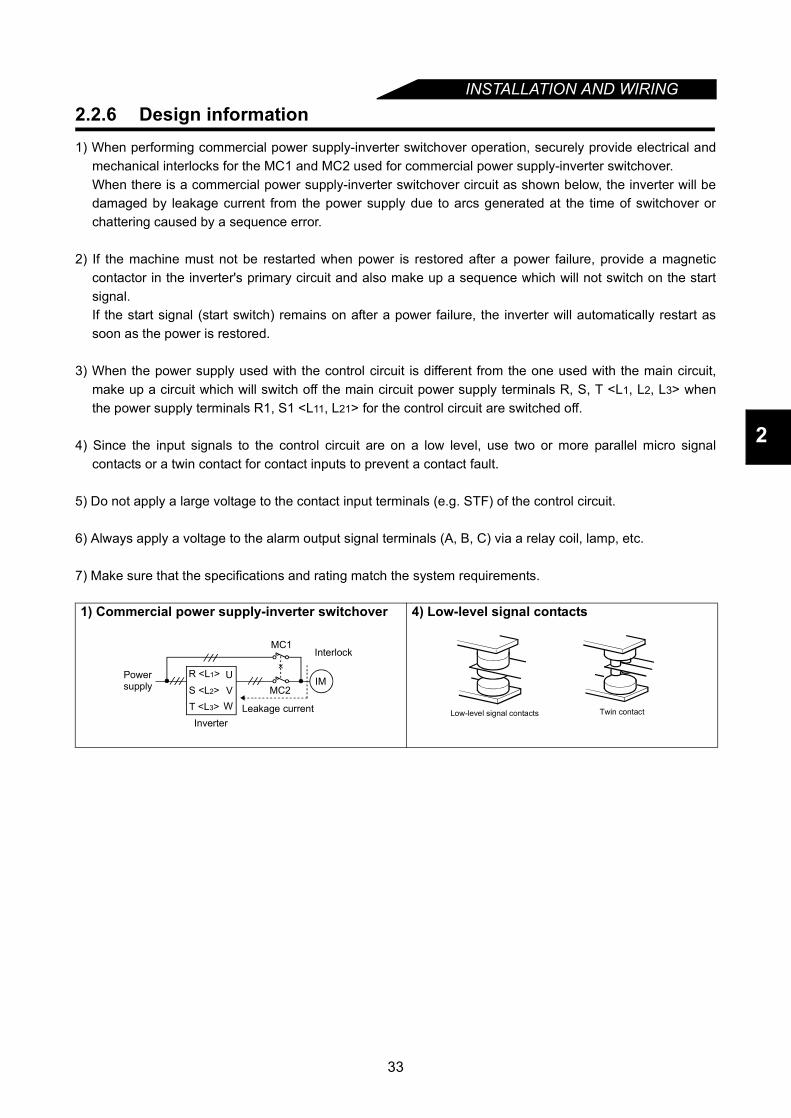
INSTALLATION AND WIRING
2
2.2.6 Design information1) When performing commercial power supply-inverter switchover operation, securely provide electrical and
mechanical interlocks for the MC1 and MC2 used for commercial power supply-inverter switchover.When there is a commercial power supply-inverter switchover circuit as shown below, the inverter will bedamaged by leakage current from the power supply due to arcs generated at the time of switchover orchattering caused by a sequence error.
2) If the machine must not be restarted when power is restored after a power failure, provide a magneticcontactor in the inverter's primary circuit and also make up a sequence which will not switch on the startsignal.If the start signal (start switch) remains on after a power failure, the inverter will automatically restart assoon as the power is restored.
3) When the power supply used with the control circuit is different from the one used with the main circuit,make up a circuit which will switch off the main circuit power supply terminals R, S, T <L1, L2, L3> whenthe power supply terminals R1, S1 <L11, L21> for the control circuit are switched off.
4) Since the input signals to the control circuit are on a low level, use two or more parallel micro signalcontacts or a twin contact for contact inputs to prevent a contact fault.
5) Do not apply a large voltage to the contact input terminals (e.g. STF) of the control circuit.
6) Always apply a voltage to the alarm output signal terminals (A, B, C) via a relay coil, lamp, etc.
7) Make sure that the specifications and rating match the system requirements.
1) Commercial power supply-inverter switchover 4) Low-level signal contacts
Interlock
Leakage currentInverter
Powersupply MC2
MC1
UVW
IMR <L1>
S <L2>T <L3> Twin contactLow-level signal contacts
33

INSTALLATION AND WIRING
2.3 Other wiring
2.3.1 Power supply harmonicsPower supply harmonics may be generated from the converter section of the inverter, affecting power supplyequipment, power capacitors, etc. Power supply harmonics are different in generation source, frequency andtransmission path from radio frequency (RF) noise and leakage currents. Take the following measures.
• The differences between harmonics and RF noise are indicated below:
2.3.2 Inverter-generated noises and their reduction techniques
Some noises enter the inverter to malfunction it and others are radiated by the inverter to malfunctionperipheral devices. Though the inverter is designed to be insusceptible to noise, it handles low-level signals,so it requires the following basic measures to be taken. Also, since the inverters chops outputs at high carrierfrequency, that could generate noise. If these noises cause peripheral devices to malfunction, measuresshould be taken to suppress the noise. These techniques differ slightly depending on noise propagationpaths.
1) Basic techniques• Do not run the power cables (I/O cables) and signal cables of the inverter in parallel with each other and
do not bundle them.• Use twisted pair shielded cables for the detector connection and control signal cables, and connect the
sheathes of the shielded cables to terminal SD.• Earth (Ground) the inverter, motor, etc. at one point.
Item Harmonics RF Noise
Frequency Normally 40th to 50th degrees or less, (up to 3kHz or less) High frequency (several 10kHz to 1GHz order)
Environment To wire paths, power impedance Across spaces, distance, laying pathsQuantitative understanding Logical computation is possible Occurs randomly, quantitative understanding is difficult.
Generated amount Approximately proportional to load capacity According to current fluctuation rate (larger with faster switching)
Immunity of affected device Specified in standards for each device. Differs according to maker's device specifications.Example of safeguard Install a reactor Increase the distance.
• SafeguardThe harmonic current generated from the inverter to thepower supply differs according to various conditions such asthe wiring impedance, whether a power factor improvingreactor is used or not, and output frequency and outputcurrent on the load side.For the output frequency and output current, the adequatemethod is to obtain them under rated load at the maximumoperating frequency.
Note: A power factor improving capacitor or surge suppressor on the inverter's output may overheat orbe damaged due to the harmonics of the inverter output. Also, since an excessive current flows inthe inverter to activate overcurrent protection, do not provide a capacitor and surge suppressor onthe inverter output side when the motor is driven by the inverter. To improve the power factor,insert a power factor improving reactor on the inverter's primary side or in the DC circuit.For details, refer to the FR-A500/E500 series technical information.
MCCB
IMInverter
Power factorimproving DCreactor
Motor
Do not insert power factor improving capacitor
Power factorimproving ACreactor
34
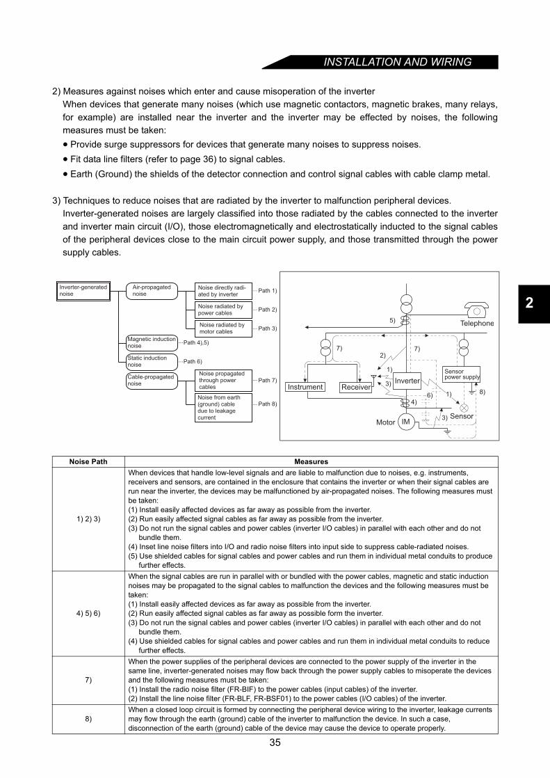
INSTALLATION AND WIRING
2
2) Measures against noises which enter and cause misoperation of the inverterWhen devices that generate many noises (which use magnetic contactors, magnetic brakes, many relays,for example) are installed near the inverter and the inverter may be effected by noises, the followingmeasures must be taken:• Provide surge suppressors for devices that generate many noises to suppress noises.• Fit data line filters (refer to page 36) to signal cables.• Earth (Ground) the shields of the detector connection and control signal cables with cable clamp metal.
3) Techniques to reduce noises that are radiated by the inverter to malfunction peripheral devices.Inverter-generated noises are largely classified into those radiated by the cables connected to the inverterand inverter main circuit (I/O), those electromagnetically and electrostatically inducted to the signal cablesof the peripheral devices close to the main circuit power supply, and those transmitted through the powersupply cables.
Noise Path Measures
1) 2) 3)
When devices that handle low-level signals and are liable to malfunction due to noises, e.g. instruments, receivers and sensors, are contained in the enclosure that contains the inverter or when their signal cables are run near the inverter, the devices may be malfunctioned by air-propagated noises. The following measures must be taken:(1) Install easily affected devices as far away as possible from the inverter.(2) Run easily affected signal cables as far away as possible from the inverter.(3) Do not run the signal cables and power cables (inverter I/O cables) in parallel with each other and do not
bundle them.(4) Inset line noise filters into I/O and radio noise filters into input side to suppress cable-radiated noises.(5) Use shielded cables for signal cables and power cables and run them in individual metal conduits to produce
further effects.
4) 5) 6)
When the signal cables are run in parallel with or bundled with the power cables, magnetic and static induction noises may be propagated to the signal cables to malfunction the devices and the following measures must be taken:(1) Install easily affected devices as far away as possible from the inverter.(2) Run easily affected signal cables as far away as possible form the inverter.(3) Do not run the signal cables and power cables (inverter I/O cables) in parallel with each other and do not
bundle them.(4) Use shielded cables for signal cables and power cables and run them in individual metal conduits to reduce
further effects.
7)
When the power supplies of the peripheral devices are connected to the power supply of the inverter in the same line, inverter-generated noises may flow back through the power supply cables to misoperate the devices and the following measures must be taken:(1) Install the radio noise filter (FR-BIF) to the power cables (input cables) of the inverter.(2) Install the line noise filter (FR-BLF, FR-BSF01) to the power cables (I/O cables) of the inverter.
8)When a closed loop circuit is formed by connecting the peripheral device wiring to the inverter, leakage currents may flow through the earth (ground) cable of the inverter to malfunction the device. In such a case, disconnection of the earth (ground) cable of the device may cause the device to operate properly.
Air-propagatednoise
Magnetic inductionnoise
Static inductionnoise
Cable-propagatednoise
Noise directly radi-ated by inverter
Noise radiated bypower cables
Noise radiated bymotor cables
Noise propagatedthrough power cables
Noise from earth(ground) cabledue to leakagecurrent
Path 4),5)
Path 6)
Path 1)
Path 2)
Path 3)
Path 7)
Path 8)
Inverter-generatednoise
...
...
...
...
...
...
...
IM
Telephone5)
7)7)2)
1)
3)
6)4)
MotorSensor
8)
Sensor power supply
ReceiverInstrumentInverter
1)
3)
35
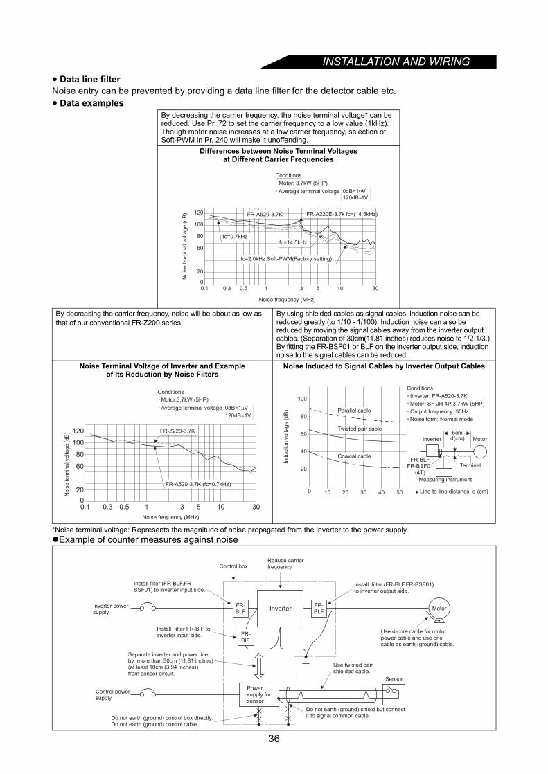
INSTALLATION AND WIRING
• Data line filterNoise entry can be prevented by providing a data line filter for the detector cable etc.• Data examples*Noise terminal voltage: Represents the magnitude of noise propagated from the inverter to the power supply.Example of counter measures against noise
By decreasing the carrier frequency, the noise terminal voltage* can be reduced. Use Pr. 72 to set the carrier frequency to a low value (1kHz).Though motor noise increases at a low carrier frequency, selection of Soft-PWM in Pr. 240 will make it unoffending.
Differences between Noise Terminal Voltagesat Different Carrier Frequencies
By decreasing the carrier frequency, noise will be about as low as that of our conventional FR-Z200 series.
By using shielded cables as signal cables, induction noise can be reduced greatly (to 1/10 - 1/100). Induction noise can also be reduced by moving the signal cables away from the inverter output cables. (Separation of 30cm(11.81 inches) reduces noise to 1/2-1/3.)By fitting the FR-BSF01 or BLF on the inverter output side, induction noise to the signal cables can be reduced.
Noise Terminal Voltage of Inverter and Example of Its Reduction by Noise Filters
Noise Induced to Signal Cables by Inverter Output Cables
0.1 0.3 0.5 1 3 5 10 30
20
60
80
100
120
0
fc=0.7kHzfc=14.5kHz
fc=2.0kHz Soft-PWM(Factory setting)
No
ise
te
rmin
al vo
lta
ge
(d
B)
Noise frequency (MHz)
Conditions
Motor: 3.7kW (5HP)
Average terminal voltage 0dB=1mV120dB=1V
FR-A220E-3.7k fc=(14.5kHz)FR-A520-3.7K
0.1 0.3 0.5 1 3 5 10 30
20
60
80
100
120
0
FR-Z220-3.7K
Noise frequency (MHz)
Nois
e term
inal voltage (
dB
)
Conditions
Motor:3.7kW (5HP)
Average terminal voltage 0dB=1µV
120dB=1V
FR-A520-3.7K (fc=0.7kHz)
20
40
60
80
100
100 20 30 40 50
5cmd(cm)
FR-BLFFR-BSF01
(4T)
Line-to-line distance, d (cm)
Ind
uctio
n v
olta
ge
(d
B) Parallel cable
Twisted pair cable
Coaxial cable
Inverter Motor
Terminal
Measuring instrument
Conditions
Inverter: FR-A520-3.7K
Motor: SF-JR 4P 3.7kW (5HP)
Output frequency: 30Hz
Noise form: Normal mode
FR-BLF
FR-BIF
FR-BLF
Install filter (FR-BLF,FR-BSF01) to inverter input side.
Control boxReduce carrierfrequency.
Install filter (FR-BLF,FR-BSF01)to inverter output side.
Use 4-core cable for motorpower cable and use onecable as earth (ground) cable.
Use twisted pairshielded cable.
Sensor
Do not earth (ground) shield but connectit to signal common cable.Do not earth (ground) control box directly.
Do not earth (ground) control cable.
Control powersupply
Install filter FR-BIF toinverter input side.
Inverter powersupply
Powersupply forsensor
Inverter Motor
Separate inverter and power line by more than 30cm (11.81 inches) (at least 10cm (3.94 inches)) from sensor circuit.
36

INSTALLATION AND WIRING
2
2.3.3 Leakage currents and countermeasuresLeakage currents flow through static capacitances existing in the inverter I/O wiring and motor. Since theirvalues depend on the static capacitances, carrier frequency, etc., take the following measures.
(1) To-earth (ground) leakage currentsLeakage currents may flow not only into the inverter's own line but also into the other line through the earth(ground) cable, etc. These leakage currents may operate earth (ground) leakage circuit breakers and earth(ground) leakage relays unnecessarily.
• Countermeasures⋅ Decrease the carrier frequency (Pr. 72) of the inverter.
Note that motor noise increases. Selection of Soft-PWM (Pr. 240) will make it unoffending.⋅ By using earth(ground) leakage circuit breakers designed for harmonic and surge suppression in the
inverter's own line and other line, operation can be performed with the carrier frequency kept high (withlow noise).
• To-earth (ground) leakage current⋅ Note that a long wiring length will increase leakage currents. Decrease the carrier frequency of the
inverter to reduce leakage currents.⋅ Higher motor capacity leads to larger leakage currents. Larger leakage currents occur in 400V class than
in 200V class.
(2) Line-to-line leakage currentsHarmonics of leakage currents flowing in static capacities between the inverter output cables may operatethe external thermal relay unnecessarily. When the wiring length is long (50m (164.04 feet) or more) for the400V class small-capacity model (7.5kW (10HP) or less), the external thermal relay is likely to operateunnecessarily because the ratio of the leakage current to the rated motor current increases.• Line-to-Line Leakage Current Data Example (200V class)
* Leakage current of the 400V class is about twice larger.
• Countermeasures⋅ Use the electronic thermal relay function (Pr. 9) of the inverter.⋅ Decrease the carrier frequency. Note that motor noise increases. Selection of Soft-PWM (Pr. 240) will
make it unoffending.To ensure that the motor is protected against line-to-line leakage currents, it is recommended to use atemperature sensor to directly detect motor temperature.
Motor Capacity(kW)
Rated MotorCurrent (A)
Leakage Current (mA)
Motor: SF-JR 4PCarrier frequency: 14.5kHz
Cable used: 2mm2 4-core captyre cable
Wiring length 50m Wiring length 100m 0.4 1.8 310 500
0.75 3.2 340 5301.5 5.8 370 5602.2 8.1 400 5903.7 12.8 440 6305.5 19.4 490 6807.5 25.6 535 725
MCCB
Line-to-Line Leakage Current Path
Power supply
Thermal relay
Line static capacitances
Motor
Inverter IM
37
INSTALLATION AND WIRING
2.3.4 Inverter-driven 400V class motorIn the PWM type inverter, a surge voltage attributable to wiring constants is generated at the motor terminals.Especially for a 400V class motor, the surge voltage may deteriorate the insulation. When the 400V classmotor is driven by the inverter, consider the following measures.• MeasuresIt is recommended to take either of the following measures:
(1) Rectifying the motor insulation
For the 400V class motor, use an insulation-rectified motor. Specifically,1) Specify the "400V class inverter-driven, insulation-rectified motor".2) For the dedicated motor such as the constant-torque motor and low-vibration motor, use the "inverter-
driven, dedicated motor".
(2) Suppressing the surge voltage on the inverter side
On the secondary side of the inverter, connect the optional surge voltage suppression filter (FR-ASF-H).
38
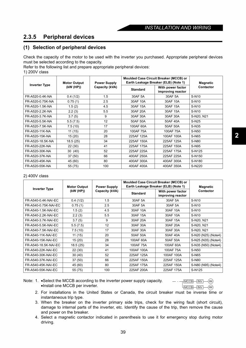
INSTALLATION AND WIRING
2
2.3.5 Peripheral devices
(1) Selection of peripheral devices
Check the capacity of the motor to be used with the inverter you purchased. Appropriate peripheral devicesmust be selected according to the capacity.Refer to the following list and prepare appropriate peripheral devices:1) 200V class
2) 400V class
Inverter Type Motor Output (kW (HP))
Power Supply Capacity (kVA)
Moulded Case Circuit Breaker (MCCB) or Earth Leakage Breaker (ELB) (Note 1) Magnetic
ContactorStandard With power factor
improving reactorFR-A520-0.4K-NA 0.4 (1/2) 1.5 30AF 5A 30AF 5A S-N10FR-A520-0.75K-NA 0.75 (1) 2.5 30AF 10A 30AF 10A S-N10FR-A520-1.5K-NA 1.5 (2) 4.5 30AF 15A 30AF 15A S-N10FR-A520-2.2K-NA 2.2 (3) 5.5 30AF 20A 30AF 15A S-N10FR-A520-3.7K-NA 3.7 (5) 9 30AF 30A 30AF 30A S-N20, N21FR-A520-5.5K-NA 5.5 (7.5) 12 50AF 50A 50AF 40A S-N25FR-A520-7.5K-NA 7.5 (10) 17 100AF 60A 50AF 50A S-N35FR-A520-11K-NA 11 (15) 20 100AF 75A 100AF 75A S-N50FR-A520-15K-NA 15 (20) 28 225AF 125A 100AF 100A S-N65FR-A520-18.5K-NA 18.5 (25) 34 225AF 150A 225AF 125A S-N80FR-A520-22K-NA 22 (30) 41 225AF 175A 225AF 150A S-N95FR-A520-30K-NA 30 (40) 52 225AF 225A 225AF 175A S-N125FR-A520-37K-NA 37 (50) 66 400AF 250A 225AF 225A S-N150FR-A520-45K-NA 45 (60) 80 400AF 300A 400AF 300A S-N180FR-A520-55K-NA 55 (75) 100 400AF 400A 400AF 350A S-N220
Inverter Type Motor Output(kW (HP))
Power Supply Capacity (kVA)
Moulded Case Circuit Breaker (MCCB) or Earth Leakage Breaker (ELB) (Note 1) Magnetic
ContactorStandard With power factor
improving reactorFR-A540-0.4K-NA/-EC 0.4 (1/2) 1.5 30AF 5A 30AF 5A S-N10FR-A540-0.75K-NA/-EC 0.75 (1) 2.5 30AF 5A 30AF 5A S-N10FR-A540-1.5K-NA/-EC 1.5 (2) 4.5 30AF 10A 30AF 10A S-N10FR-A540-2.2K-NA/-EC 2.2 (3) 5.5 30AF 15A 30AF 10A S-N10FR-A540-3.7K-NA/-EC 3.7 (5) 9 30AF 20A 30AF 15A S-N20, N21FR-A540-5.5K-NA/-EC 5.5 (7.5) 12 30AF 30A 30AF 20A S-N20, N21FR-A540-7.5K-NA/-EC 7.5 (10) 17 30AF 30A 30AF 30A S-N20, N21FR-A540-11K-NA/-EC 11 (15) 20 50AF 50A 50AF 40A S-N20 (N25) (Note4)FR-A540-15K-NA/-EC 15 (20) 28 100AF 60A 50AF 50A S-N25 (N35) (Note4)FR-A540-18.5K-NA/-EC 18.5 (25) 34 100AF 75A 100AF 60A S-N35 (N50) (Note4)FR-A540-22K-NA/-EC 22 (30) 41 100AF 100A 100AF 75A S-N50FR-A540-30K-NA/-EC 30 (40) 52 225AF 125A 100AF 100A S-N65FR-A540-37K-NA/-EC 37 (50) 66 225AF 150A 225AF 125A S-N80FR-A540-45K-NA/-EC 45 (60) 80 225AF 175A 225AF 150A S-N80 (N95) (Note4)FR-A540-55K-NA/-EC 55 (75) 100 225AF 200A 225AF 175A S-N125
Note: 1. •Select the MCCB according to the inverter power supply capacity.•Install one MCCB per inverter.
2. For installations in the United States or Canada, the circuit breaker must be inverse time orinstantaneous trip type.
3. When the breaker on the inverter primary side trips, check for the wiring fault (short circuit),damage to internal parts of the inverter, etc. Identify the cause of the trip, then remove the causeand power on the breaker.
4. Select a magnetic contactor indicated in parenthesis to use it for emergency stop during motordriving.
MCCB INV
MCCB INV
IM
IM
39
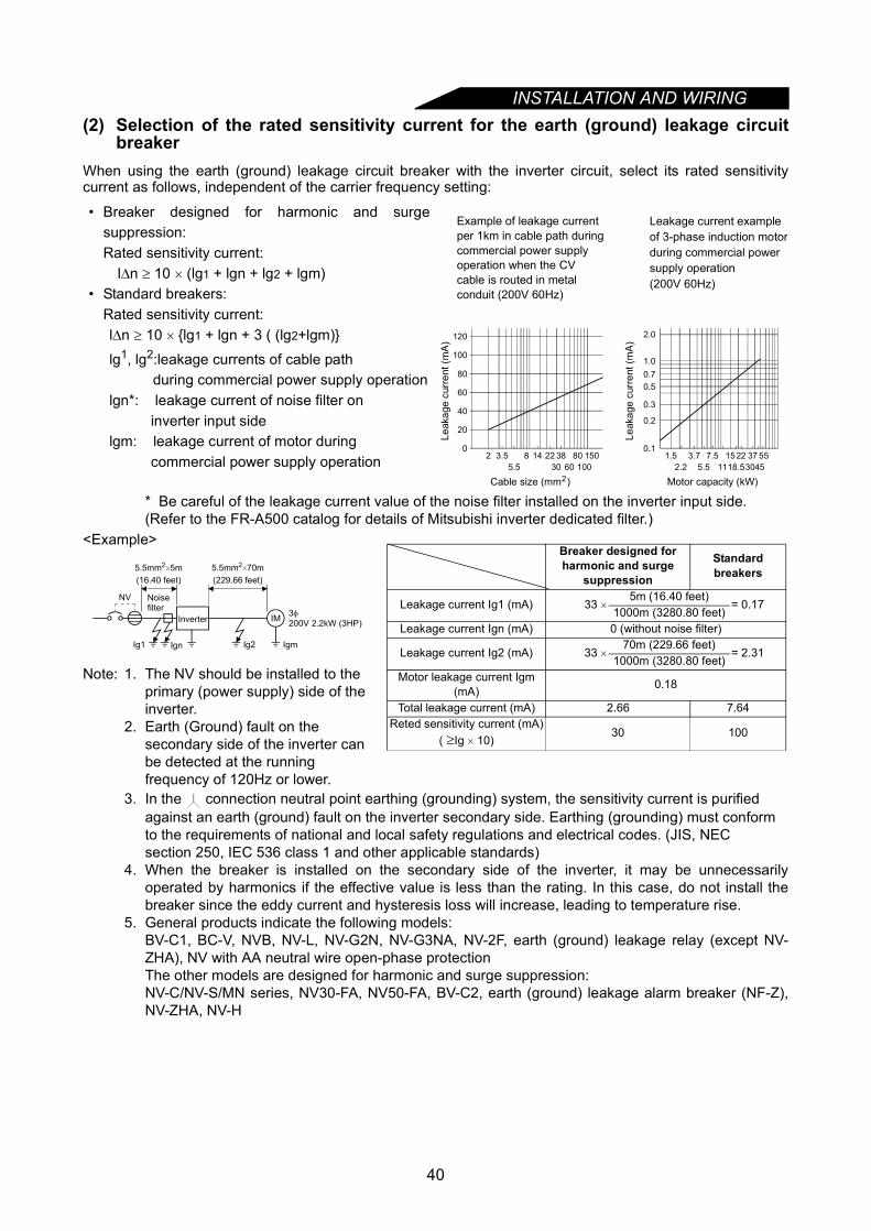
INSTALLATION AND WIRING
(2) Selection of the rated sensitivity current for the earth (ground) leakage circuitbreakerWhen using the earth (ground) leakage circuit breaker with the inverter circuit, select its rated sensitivitycurrent as follows, independent of the carrier frequency setting:
* Be careful of the leakage current value of the noise filter installed on the inverter input side.(Refer to the FR-A500 catalog for details of Mitsubishi inverter dedicated filter.)
<Example>
Note: 1. The NV should be installed to the primary (power supply) side of the inverter.
2. Earth (Ground) fault on the secondary side of the inverter can be detected at the running frequency of 120Hz or lower.
3. In the connection neutral point earthing (grounding) system, the sensitivity current is purified against an earth (ground) fault on the inverter secondary side. Earthing (grounding) must conform to the requirements of national and local safety regulations and electrical codes. (JIS, NEC section 250, IEC 536 class 1 and other applicable standards)
4. When the breaker is installed on the secondary side of the inverter, it may be unnecessarilyoperated by harmonics if the effective value is less than the rating. In this case, do not install thebreaker since the eddy current and hysteresis loss will increase, leading to temperature rise.
5. General products indicate the following models: BV-C1, BC-V, NVB, NV-L, NV-G2N, NV-G3NA, NV-2F, earth (ground) leakage relay (except NV-ZHA), NV with AA neutral wire open-phase protectionThe other models are designed for harmonic and surge suppression: NV-C/NV-S/MN series, NV30-FA, NV50-FA, BV-C2, earth (ground) leakage alarm breaker (NF-Z),NV-ZHA, NV-H
• Breaker designed for harmonic and surgesuppression: Rated sensitivity current:
l∆n ≥ 10 × (lg1 + lgn + lg2 + lgm)• Standard breakers:
Rated sensitivity current: l∆n ≥ 10 × lg1 + lgn + 3 ( (lg2+lgm)
lg1, lg2:leakage currents of cable path during commercial power supply operation
lgn*: leakage current of noise filter on inverter input side
lgm: leakage current of motor during commercial power supply operation
0
20
40
60
80
100
120
2 3.55.5
8 14 2230
3860
80100
1500.1
1.5 3.72.2
7.5 152211
3730
5545
0.2
0.3
0.50.71.0
2.0
5.5 18.5
Leakage current exampleof 3-phase induction motorduring commercial powersupply operation(200V 60Hz)
Leak
age
curr
ent (
mA
)
Leak
age
curr
ent (
mA
)
Cable size (mm )2 Motor capacity (kW)
Example of leakage current per 1km in cable path during commercial power supplyoperation when the CV cable is routed in metal conduit (200V 60Hz)
Breaker designed for harmonic and surge
suppression
Standard breakers
Leakage current Ig1 (mA) 33 ×5m (16.40 feet)
= 0.171000m (3280.80 feet)
Leakage current Ign (mA) 0 (without noise filter)
Leakage current Ig2 (mA) 33 ×70m (229.66 feet)
= 2.311000m (3280.80 feet)
Motor leakage current Igm (mA) 0.18
Total leakage current (mA) 2.66 7.64Reted sensitivity current (mA)
( ≥Ig × 10)30 100
NV
Ig1 Ign Ig2 Igm
IMInverter
Noisefilter
5.5mm2×5m(16.40 feet)
5.5mm2×70m(229.66 feet)
3φ200V 2.2kW (3HP)
40

INSTALLATION AND WIRING
2
(3) Power-off and magnetic contactor (MC)
On the inverter primary side, it is recommended to provide an MC for the following purposes (Refer to page39 for selection.):1)To release the inverter from the power supply when the inverter protective function is activated or the drive
becomes faulty (e.g. emergency stop operation).When cycle operation or heavy-duty operation is performed with an optional brake resistor connected,overheat and burnout of the electrical-discharge resistor can be prevented if a regenerative braketransistor is damaged due to insufficient heat capacity of the electrical-discharge resistor and excessregenerative brake duty.
2)To prevent an accident due to an automatic restart made at power restoration after an inverter stop madeby a power failure.
3)To rest the inverter for an extended period of time.The control power supply for inverter is always running and consumes a little power. When stopping theinverter for an extended period of time, powering off the inverter will save power slightly.
4)To separate the inverter from the power supply to ensure safe maintenance and inspection work.As the inverter's primary MC is used for the above purposes, select the one of class JEM1038-AC3 for theinverter input side current when making an emergency stop during normal operation.
Note: The MC may be switched on/off to start/stop the inverter. However, since reapeated inrushcurrents at power-on will shorten the life of the converter circuit (swithing life is about 100,000times), frequent starts and stops must be avoided. Turn on/off the inverter start controllingterminals (STF, STR) to run/stop the inverter.
•Circuit example of start/stop of the inverter.As shown on the right, always use the start signal (ON or OFF across terminals STF or STR-SD) to make a start or stop. (Refer to page 13.)
REMARKS*1. For the 400V class power supply, install a voltage-reducing transformer.*2. Connect the power supply terminals R1 and S1 <L11 and L21> of the control circuit to the primary side of the MC to hold an
alarm signal when the inverter's protective circuit is activated. At this time, remove jumpers across terminals R-R1 and S-S1<L1-L11, L2-L21>. (For removal of jumpers, refer to page 20)
MCCB
OFFON
MCMC
RA
U
V
W
SD
MC
STF(STR)
RARA
MC
T *1
A
B
C
Power
supply To motor
Inverter
Start/Stop
OFF
Operation
Operation ready
R<L1>
S<L2>
T<L3>
R1<L11>
S1<L21>*2
41
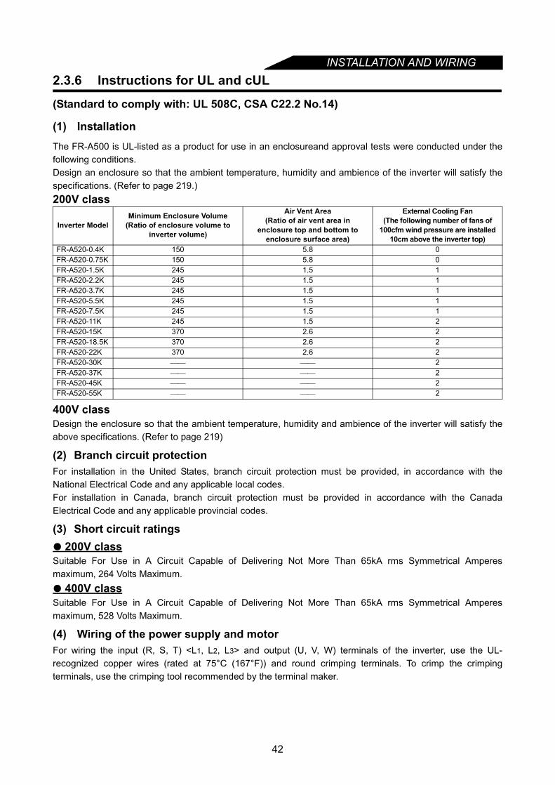
INSTALLATION AND WIRING
2.3.6 Instructions for UL and cUL(Standard to comply with: UL 508C, CSA C22.2 No.14)
(1) InstallationThe FR-A500 is UL-listed as a product for use in an enclosureand approval tests were conducted under thefollowing conditions. Design an enclosure so that the ambient temperature, humidity and ambience of the inverter will satisfy thespecifications. (Refer to page 219.)200V class
400V classDesign the enclosure so that the ambient temperature, humidity and ambience of the inverter will satisfy theabove specifications. (Refer to page 219)
(2) Branch circuit protectionFor installation in the United States, branch circuit protection must be provided, in accordance with theNational Electrical Code and any applicable local codes.For installation in Canada, branch circuit protection must be provided in accordance with the CanadaElectrical Code and any applicable provincial codes.
(3) Short circuit ratings 200V class
Suitable For Use in A Circuit Capable of Delivering Not More Than 65kA rms Symmetrical Amperesmaximum, 264 Volts Maximum.
400V classSuitable For Use in A Circuit Capable of Delivering Not More Than 65kA rms Symmetrical Amperesmaximum, 528 Volts Maximum.
(4) Wiring of the power supply and motorFor wiring the input (R, S, T) <L1, L2, L3> and output (U, V, W) terminals of the inverter, use the UL-recognized copper wires (rated at 75°C (167°F)) and round crimping terminals. To crimp the crimpingterminals, use the crimping tool recommended by the terminal maker.
Inverter ModelMinimum Enclosure Volume
(Ratio of enclosure volume to inverter volume)
Air Vent Area (Ratio of air vent area in
enclosure top and bottom to enclosure surface area)
External Cooling Fan (The following number of fans of
100cfm wind pressure are installed 10cm above the inverter top)
FR-A520-0.4K 150 5.8 0FR-A520-0.75K 150 5.8 0FR-A520-1.5K 245 1.5 1FR-A520-2.2K 245 1.5 1FR-A520-3.7K 245 1.5 1FR-A520-5.5K 245 1.5 1FR-A520-7.5K 245 1.5 1FR-A520-11K 245 1.5 2FR-A520-15K 370 2.6 2FR-A520-18.5K 370 2.6 2FR-A520-22K 370 2.6 2FR-A520-30K 2FR-A520-37K 2FR-A520-45K 2FR-A520-55K 2
42
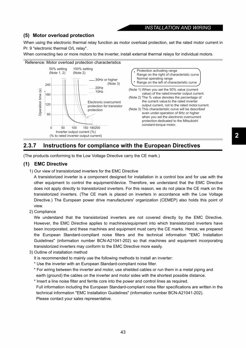
INSTALLATION AND WIRING
2
(5) Motor overload protectionWhen using the electronic thermal relay function as motor overload protection, set the rated motor current inPr. 9 "electronic thermal O/L relay".When connecting two or more motors to the inverter, install external thermal relays for individual motors.
2.3.7 Instructions for compliance with the European Directives(The products conforming to the Low Voltage Directive carry the CE mark.)
(1) EMC Directive1) Our view of transistorized inverters for the EMC Directive
A transistorized inverter is a component designed for installation in a control box and for use with theother equipment to control the equipment/device. Therefore, we understand that the EMC Directivedoes not apply directly to transistorized inverters. For this reason, we do not place the CE mark on thetransistorized inverters. (The CE mark is placed on inverters in accordance with the Low VoltageDirective.) The European power drive manufacturers' organization (CEMEP) also holds this point ofview.
2) ComplianceWe understand that the transistorized inverters are not covered directly by the EMC Directive.However, the EMC Directive applies to machines/equipment into which transistorized inverters havebeen incorporated, and these machines and equipment must carry the CE marks. Hence, we preparedthe European Standard-compliant noise filters and the technical information "EMC InstallationGuidelines" (information number BCN-A21041-202) so that machines and equipment incorporatingtransistorized inverters may conform to the EMC Directive more easily.
3) Outline of installation methodIt is recommended to mainly use the following methods to install an inverter:* Use the inverter with an European Standard-compliant noise filter.* For wiring between the inverter and motor, use shielded cables or run them in a metal piping and
earth (ground) the cables on the inverter and motor sides with the shortest possible distance.* Insert a line noise filter and ferrite core into the power and control lines as required.
Full information including the European Standard-compliant noise filter specifications are written in thetechnical information "EMC Installation Guidelines" (information number BCN-A21041-202).Please contact your sales representative.
Reference: Motor overload protection characteristics
(Note 1) When you set the 50% value (current value) of the rated inverter output current.(Note 2) The % value denotes the percentage of the current value to the rated inverter output current, not to the rated motor current.(Note 3) This characteristic curve will be described even under operation of 6Hz or higher when you set the electronic overcurrent protection dedicated to the Mitsubishi constant-torque motor.
Protection activating range Range on the right of characteristic curveNormal operating rangeRange on the left of characteristic curve
0 50 100 150 180200
240
180
120
60Op
era
tio
n t
ime
(s)
50% setting(Note 1, 2)
100% setting(Note 2)
30Hz or higher (Note 3)
Inverter output current (%)(% to rated inverter output current)
Electronic overcurrent protection for transistorprotection
20Hz10Hz
43
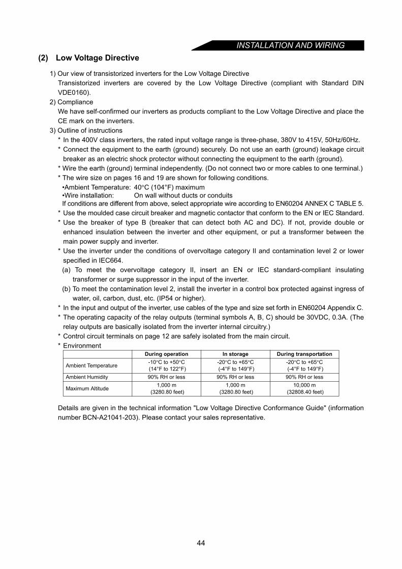
INSTALLATION AND WIRING
(2) Low Voltage Directive1) Our view of transistorized inverters for the Low Voltage DirectiveTransistorized inverters are covered by the Low Voltage Directive (compliant with Standard DINVDE0160).
2) ComplianceWe have self-confirmed our inverters as products compliant to the Low Voltage Directive and place theCE mark on the inverters.
3) Outline of instructions* In the 400V class inverters, the rated input voltage range is three-phase, 380V to 415V, 50Hz/60Hz.* Connect the equipment to the earth (ground) securely. Do not use an earth (ground) leakage circuit
breaker as an electric shock protector without connecting the equipment to the earth (ground).* Wire the earth (ground) terminal independently. (Do not connect two or more cables to one terminal.)* The wire size on pages 16 and 19 are shown for following conditions.
•Ambient Temperature: 40°C (104°F) maximum•Wire installation: On wall without ducts or conduitsIf conditions are different from above, select appropriate wire according to EN60204 ANNEX C TABLE 5.
* Use the moulded case circuit breaker and magnetic contactor that conform to the EN or IEC Standard.* Use the breaker of type B (breaker that can detect both AC and DC). If not, provide double or
enhanced insulation between the inverter and other equipment, or put a transformer between themain power supply and inverter.
* Use the inverter under the conditions of overvoltage category II and contamination level 2 or lowerspecified in IEC664.(a) To meet the overvoltage category II, insert an EN or IEC standard-compliant insulating
transformer or surge suppressor in the input of the inverter.(b) To meet the contamination level 2, install the inverter in a control box protected against ingress of
water, oil, carbon, dust, etc. (IP54 or higher).* In the input and output of the inverter, use cables of the type and size set forth in EN60204 Appendix C.* The operating capacity of the relay outputs (terminal symbols A, B, C) should be 30VDC, 0.3A. (The
relay outputs are basically isolated from the inverter internal circuitry.)* Control circuit terminals on page 12 are safely isolated from the main circuit.* Environment
Details are given in the technical information "Low Voltage Directive Conformance Guide" (informationnumber BCN-A21041-203). Please contact your sales representative.
During operation In storage During transportation
Ambient Temperature -10°C to +50°C (14°F to 122°F)
-20°C to +65°C (-4°F to 149°F)
-20°C to +65°C (-4°F to 149°F)
Ambient Humidity 90% RH or less 90% RH or less 90% RH or less
Maximum Altitude 1,000 m (3280.80 feet)
1,000 m (3280.80 feet)
10,000 m (32808.40 feet)
44

INSTALLATION AND WIRING
2
2.3.8 Earthing (EC version)
(1) Earthing and Earth Leakage Current(a) Purpose of Earthing
Electrical equipment usually has an Earthing Terminal, this must be connected to earth before usingequipment.For protection, electric circuits are normally housed inside an insulated case. However it is impossibleto manufacture insulating materials that prevent all current from leaking across them, therefore it isthe function of the earth (safety earth) to prevent electric shocks when touching the case.There is however, another important earthing function, which is to prevent equipment that uses veryweak signals (Audio equipment, sensors, transducers, etc.) or micro processors from being affectedby Radio Frequency Interference, (RFI) from external sources.
(b) Points to remember when EarthingAs detailed above there are two entirely different types of earthing and to attempt to use the sameearth for both will lead to problems. It is necessary to separate the "safety" earthing (a yellow/greenwire to prevent electric shocks) from the "FRI" earthing (a braided wire strap to counter radio noise).The inverter output voltage does not take the form of a sine wave but of a modulated pulse wave formcausing "noisy" leakage current due to the capacitance of the insulation.The same type of leakage current will occur in the motor due to the charging and discharging of theinsulation from the high frequency wave form. This trend becomes more pronounced with highercarrier frequencies.To solve this problem it is necessary to use separate "dirty" earthing for inverter and motorinstallations an "clean" earting for equipment such as sensors, computers and audio equipment.
(2) Earthing methodsTwo main types of earth
1-To prevent electrical shocksYellow and green cable
2-To prevent RFI induced malfunctionBraided strap
It is important to make a clear distinction between these two, and to keep them separate by following themeasures below.a) When possible earth the inverter independently of other equipment.
If independent earthing is not possible, use a common earthing point.Avoid connecting earthing wires together particularly on high power equipment such as motors andinverters.Independent earthing should always be used between sensitive equipment and inverters.
b) Safety earths should be...For 400V duty - 10Ω or lessFor 200V duty - 100Ω or less
c) The safety earth should be as thick as possible, minimum thickness as stated in below table.d) The earthing point should be as close to the inverter as possible, and the wire as short as possible.
Other
equipmentInverter
Other
equipmentInverter
Other
equipmentInverter
(a) Independent earthing (b) common earthing (c) Grounding wire of
other equipment
45
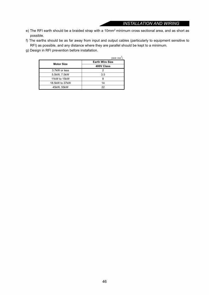
INSTALLATION AND WIRING
e) The RFI earth should be a braided strap with a 10mm2 minimum cross sectional area, and as short aspossible.f) The earths should be as far away from input and output cables (particularly to equipment sensitive to
RFI) as possible, and any distance where they are parallel should be kept to a minimum.g) Design in RFI prevention before installation.
(Unit: mm2)
Motor SizeEarth Wire Size
400V Class3.7kW or less 25.5kW, 7.5kW 3.511kW to 15kW 8
18.5kW to 37kW 1445kW, 55kW 22
46

CHAPTER 3
OPERATION/CONTROLChapter 1
Chapter 2
Chapter 4
Chapter 5
Chapter 6
Chapter 7
Chapter 8
Chapter 3
This chapter explains the basic "operation/control" for use of thisproduct.Always read the instructions and other information before usingthe equipment.
3.1 Pre-Operation Information.....................................483.2 Operation Panel ....................................................513.3 Operation...............................................................57
47
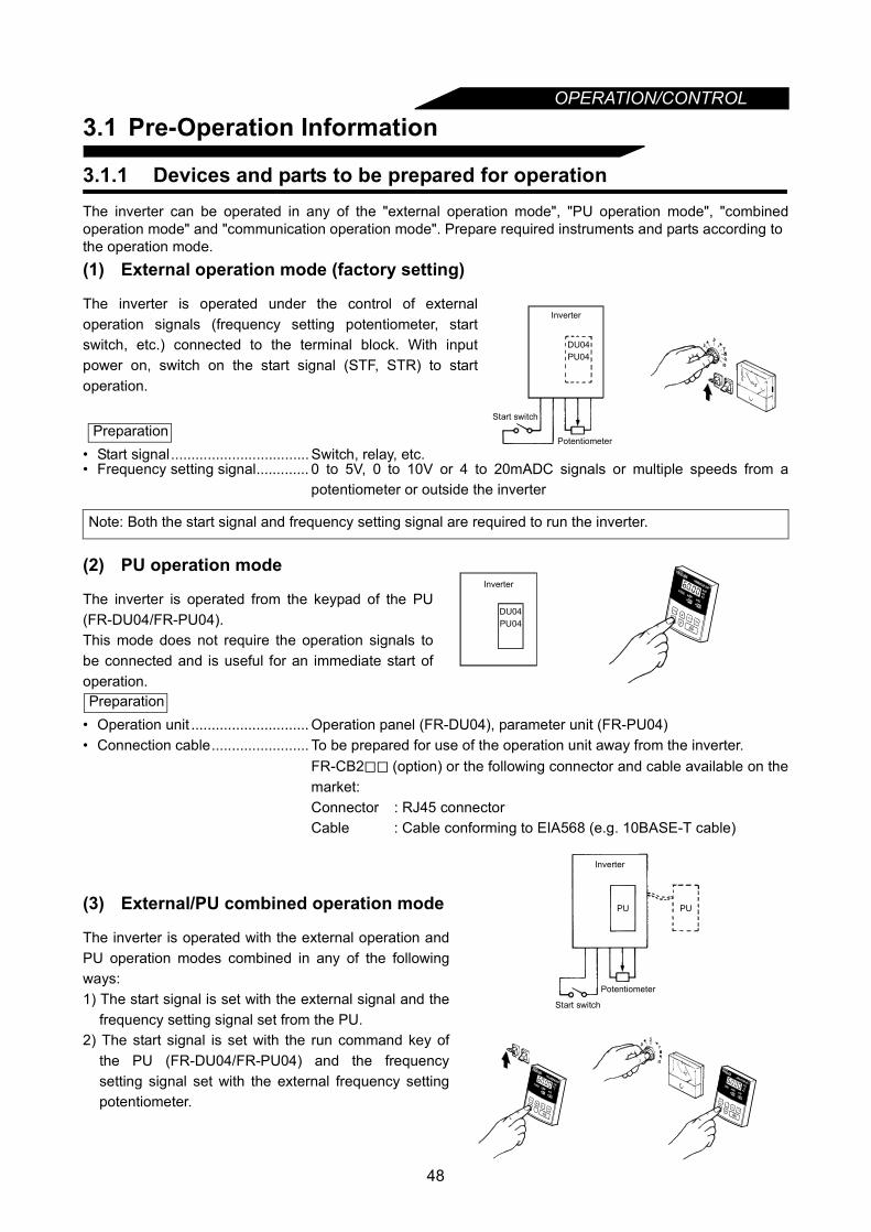
OPERATION/CONTROL
3.1 Pre-Operation Information
3.1.1 Devices and parts to be prepared for operationThe inverter can be operated in any of the "external operation mode", "PU operation mode", "combinedoperation mode" and "communication operation mode". Prepare required instruments and parts according to the operation mode.
• Frequency setting signal............. 0 to 5V, 0 to 10V or 4 to 20mADC signals or multiple speeds from apotentiometer or outside the inverter
• Operation unit ............................. Operation panel (FR-DU04), parameter unit (FR-PU04)• Connection cable........................ To be prepared for use of the operation unit away from the inverter.
FR-CB2 (option) or the following connector and cable available on themarket:Connector : RJ45 connectorCable : Cable conforming to EIA568 (e.g. 10BASE-T cable)
(1) External operation mode (factory setting)
The inverter is operated under the control of externaloperation signals (frequency setting potentiometer, startswitch, etc.) connected to the terminal block. With inputpower on, switch on the start signal (STF, STR) to startoperation.
• Start signal.................................. Switch, relay, etc.
Note: Both the start signal and frequency setting signal are required to run the inverter.
(2) PU operation mode
The inverter is operated from the keypad of the PU(FR-DU04/FR-PU04).This mode does not require the operation signals tobe connected and is useful for an immediate start ofoperation.
(3) External/PU combined operation mode
The inverter is operated with the external operation andPU operation modes combined in any of the followingways:1) The start signal is set with the external signal and the
frequency setting signal set from the PU.2) The start signal is set with the run command key of
the PU (FR-DU04/FR-PU04) and the frequencysetting signal set with the external frequency settingpotentiometer.
Preparation
DU04PU04
Potentiometer
Inverter
Start switch
DU04PU04
Inverter
Preparation
PU PU
Potentiometer
Inverter
Start switch
48
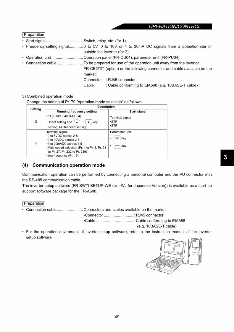
OPERATION/CONTROL
3
• Start signal.................................. Switch, relay, etc. (for 1)• Frequency setting signal............. 0 to 5V, 0 to 10V or 4 to 20mA DC signals from a potentiometer or
outside the inverter (for 2)• Operation unit ............................. Operation panel (FR-DU04), parameter unit (FR-PU04)• Connection cable........................ To be prepared for use of the operation unit away from the inverter
FR-CB2 (option) or the following connector and cable available on themarket:Connector : RJ45 connectorCable : Cable conforming to EIA568 (e.g. 10BASE-T cable)
3) Combined operation modeChange the setting of Pr. 79 "operation mode selection" as follows:
(4) Communication operation mode
Communication operation can be performed by connecting a personal computer and the PU connector withthe RS-485 communication cable.The inverter setup software (FR-SW -SETUP-WE (or - WJ for Japanese Version)) is available as a start-upsupport software package for the FR-A500.
• Connection cable........................ Connectors and cables available on the market•Connector ........................... : RJ45 connector•Cable .................................. : Cable conforming to EIA568
(e.g. 10BASE-T cable)• For the operation enviroment of inverter setup software, refer to the instruction manual of the inverter
setup software.
SettingDescription
Running frequency setting Start signal
3PU (FR-DU04/FR-PU04)
•Direct setting and / key setting, Multi-speed setting
Terminal signal•STF•STR
4
Terminal signal•0 to 5VDC across 2-5•0 to 10VDC across 2-5•4 to 20mADC across 4-5•Multi-speed selection (Pr. 4 to Pr. 6, Pr. 24 to Pr. 27, Pr. 232 to Pr. 239)
•Jog frequency (Pr. 15)
Parameter unit
• key
• key
Preparation
FWD
REV
Preparation
49
OPERATION/CONTROL
3.1.2 Power onBefore switching power on, check the following.
Installation check
Make sure that the inverter is installed correctly in a proper location. (Refer to page 10.)•Wiring checkMake sure that the main and control circuits are wired correctly.Make sure that the options and peripheral devices are selected and connected correctly. (Refer to page 12.)
Switch power on.
Power-on is complete when the POWER lamp is lit correctly and the operation panel (FR-DU04)displays correct data.
50

OPERATION/CONTROL
3
3.2 Operation PanelWith the operation panel (FR-DU04), you can set the running frequency, monitor the operation commanddisplay, set parameters, display an error, and copy parameters.
3.2.1 Names and functions of the operation panel (FR-DU04)
•Key indications
•Unit indications, operating status indications
Key Description
key You can select the operation mode or setting mode.
key You can determine the frequency and parameter setting.
key• Used to increase or decrease the running frequency consecutively. Hold down this key to change the
frequency.• Press this key in the setting mode to change the parameter setting consecutively.
key Used to give a forward rotation command.
key Used to give a reverse rotation command.
key • Used to stop operation.• Used to reset the inverter when its output is stopped by the protective function activated (major fault).
Indication DescriptionHz Lit to indicate the frequency. A Lit to indicate the current.V Lit to indicate the voltage.
MON Lit in the monitor display mode.PU Lit in the PU operation mode.
EXT Lit in external operation mode.FWD Flickers to indicate forward rotation.REV Flickers to indicate reverse rotation.
DisplayLED ×4 digits
Mode key
Set key
Unit indication Hz (frequency) A (current) V (voltage)
Operation status indication
Forward rotation key
Stop and reset key
FR-DU04HzAV
MON EXT PU
CONTROL PANEL
FWD
MODE
SET
REV FWD
STOPRESET
REV
Up down key
Reverse rotation key
MODE
SET
FWD
REV
STOPRESET
51
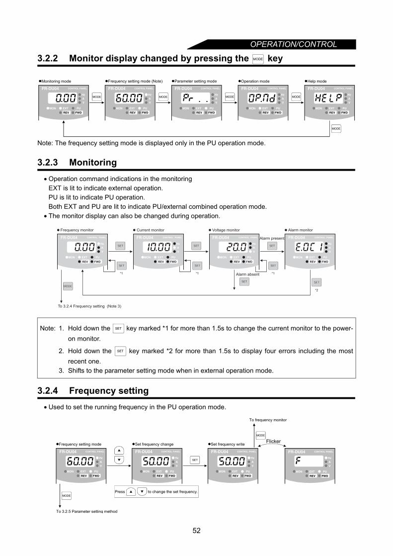
OPERATION/CONTROL
3.2.2 Monitor display changed by pressing the key
Note: The frequency setting mode is displayed only in the PU operation mode.
3.2.3 Monitoring• Operation command indications in the monitoring
EXT is lit to indicate external operation.PU is lit to indicate PU operation.Both EXT and PU are lit to indicate PU/external combined operation mode.
• The monitor display can also be changed during operation.
3.2.4 Frequency setting• Used to set the running frequency in the PU operation mode.
Note: 1. Hold down the key marked *1 for more than 1.5s to change the current monitor to the power-on monitor.
2. Hold down the key marked *2 for more than 1.5s to display four errors including the mostrecent one.
3. Shifts to the parameter setting mode when in external operation mode.
MODE
MODE MODE MODE MODE
MODE
Help modeMonitoring mode Parameter setting mode Operation mode
FR-DU04 CONTROL PANEL
Hz
MON EXT PU
AV
REV FWD
Frequency setting mode (Note)
FR-DU04 CONTROL PANEL
Hz
MON EXT PU
AV
REV FWD
FR-DU04 CONTROL PANEL
Hz
MON EXT PU
AV
REV FWD
FR-DU04 CONTROL PANEL
Hz
MON EXT PU
AV
REV FWD
FR-DU04 CONTROL PANEL
Hz
MON EXT PU
AV
REV FWD
To 3.2.4 Frequency setting (Note 3)
Frequency monitor Current monitor Voltage monitor Alarm monitor
Alarm present
Alarm absent*1 *1 *1
*2
SET
SET
MODE
SET
MODE
To 3.2.5 Parameter setting method
Set frequency writeSet frequency change
Press to change the set frequency.
To frequency monitor
FR-DU04 CONTROL PANEL
Hz
MON EXT PU
AV
REV FWD
FR-DU04 CONTROL PANEL
Hz
MON EXT PU
AV
REV FWD
FR-DU04 CONTROL PANEL
Hz
MON EXT PU
AV
REV FWD
Frequency setting mode Flicker
FR-DU04 CONTROL PANEL
Hz
MON EXT PU
AV
REV FWD
52
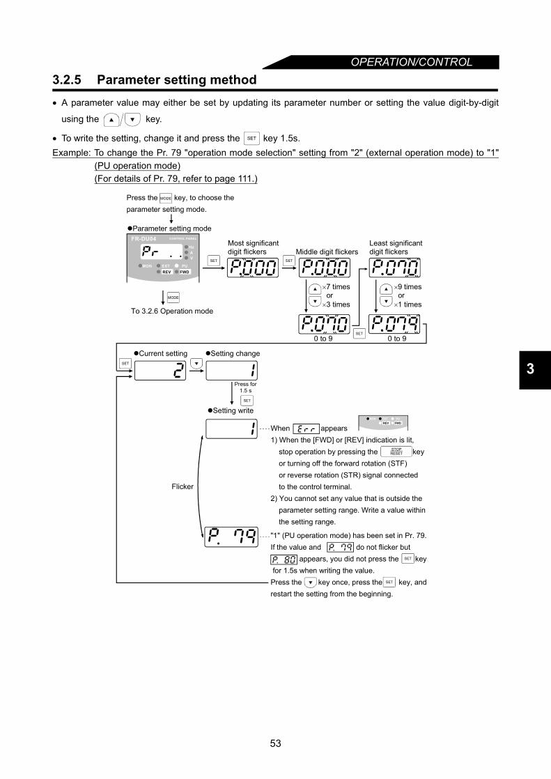
OPERATION/CONTROL
3
3.2.5 Parameter setting method• A parameter value may either be set by updating its parameter number or setting the value digit-by-digit
using the key.
• To write the setting, change it and press the key 1.5s.Example: To change the Pr. 79 "operation mode selection" setting from "2" (external operation mode) to "1"
(PU operation mode)(For details of Pr. 79, refer to page 111.)
SET
STOPRESET
MODE
SET
SET
SET
SET
SET
SET SET
When appears1) When the [FWD] or [REV] indication is lit, stop operation by pressing the key or turning off the forward rotation (STF) or reverse rotation (STR) signal connected to the control terminal.2) You cannot set any value that is outside the parameter setting range. Write a value within the setting range.
Current setting Setting change
Press for1.5 s
Middle digit flickersMost significantdigit flickers
Least significantdigit flickers
0 to 9
Setting write
Flicker
To 3.2.6 Operation mode
0 to 9
×7 times or×3 times
×9 times or×1 times
"1" (PU operation mode) has been set in Pr. 79.If the value and do not flicker but appears, you did not press the key for 1.5s when writing the value.Press the key once, press the key, and restart the setting from the beginning.
FR-DU04 CONTROL PANEL
Hz
MON EXT PU
AV
REV FWD
MON EXT PUREV FWD
Parameter setting mode
Press the key, to choose the parameter setting mode.
MODE
53

OPERATION/CONTROL
3.2.6 Operation mode
Note: If the operation mode cannot be changed, refer to page 204.
3.2.7 Help mode
(1) Alarm historyFour past alarms can be displayed with the key.("." is appended to the most recent alarm.)When no alarm exists, E._ _0 is displayed.
MODE MODEMODE
To 3.2.7 Help mode
External operation PU operation PU jog operation
FR-DU04 CONTROL PANEL
Hz
MON EXT PU
AV
REV FWD
FR-DU04 CONTROL PANEL
Hz
MON EXT PU
AV
REV FWD
FR-DU04 CONTROL PANEL
Hz
MON EXT PU
AV
REV FWD
MODE
To 3.2.3 Monitoring
Alarm history Alarm history clear
Parameter clear All clear User clear Software version readFR-DU04 CONTROL PANEL
Hz
MON EXT PU
AV
REV FWD
Most recent alarm
Frequency Current Voltage
Cumulative
energization time
At alarm occurrence
54
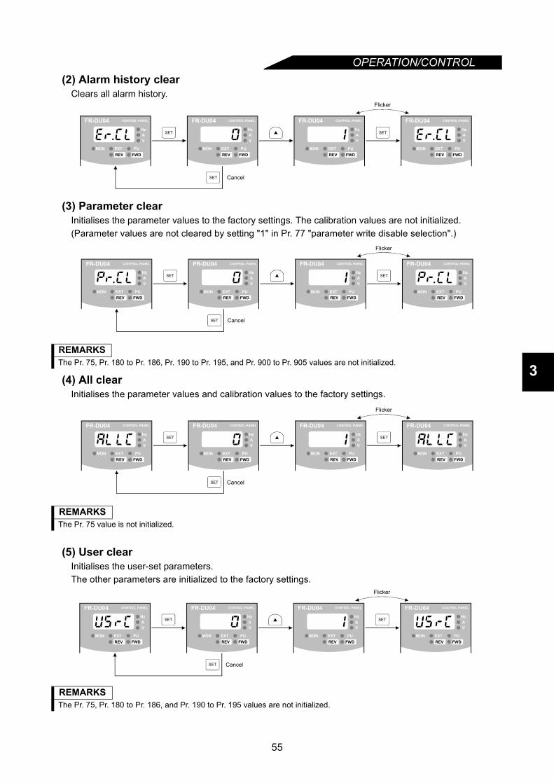
OPERATION/CONTROL
3
(2) Alarm history clearClears all alarm history.
(3) Parameter clearInitialises the parameter values to the factory settings. The calibration values are not initialized.(Parameter values are not cleared by setting "1" in Pr. 77 "parameter write disable selection".)
(4) All clearInitialises the parameter values and calibration values to the factory settings.
(5) User clearInitialises the user-set parameters.The other parameters are initialized to the factory settings.
REMARKSThe Pr. 75, Pr. 180 to Pr. 186, Pr. 190 to Pr. 195, and Pr. 900 to Pr. 905 values are not initialized.
REMARKSThe Pr. 75 value is not initialized.
REMARKSThe Pr. 75, Pr. 180 to Pr. 186, and Pr. 190 to Pr. 195 values are not initialized.
SET SET
SET
Flicker
Cancel
FR-DU04 CONTROL PANEL
Hz
MON EXT PU
AV
REV FWD
FR-DU04 CONTROL PANEL
Hz
MON EXT PU
AV
REV FWD
FR-DU04 CONTROL PANEL
Hz
MON EXT PU
AV
REV FWD
FR-DU04 CONTROL PANEL
Hz
MON EXT PU
AV
REV FWD
SET SET
SET
Flicker
Cancel
FR-DU04 CONTROL PANEL
Hz
MON EXT PU
AV
REV FWD
FR-DU04 CONTROL PANEL
Hz
MON EXT PU
AV
REV FWD
FR-DU04 CONTROL PANEL
Hz
MON EXT PU
AV
REV FWD
FR-DU04 CONTROL PANEL
Hz
MON EXT PU
AV
REV FWD
SET SET
SET
Flicker
Cancel
FR-DU04 CONTROL PANEL
Hz
MON EXT PU
AV
REV FWD
FR-DU04 CONTROL PANEL
Hz
MON EXT PU
AV
REV FWD
FR-DU04 CONTROL PANEL
Hz
MON EXT PU
AV
REV FWD
FR-DU04 CONTROL PANEL
Hz
MON EXT PU
AV
REV FWD
SET SET
SET
Flicker
Cancel
FR-DU04 CONTROL PANEL
Hz
MON EXT PU
AV
REV FWD
FR-DU04 CONTROL PANEL
Hz
MON EXT PU
AV
REV FWD
FR-DU04 CONTROL PANEL
Hz
MON EXT PU
AV
REV FWD
FR-DU04 CONTROL PANEL
Hz
MON EXT PU
AV
REV FWD
55
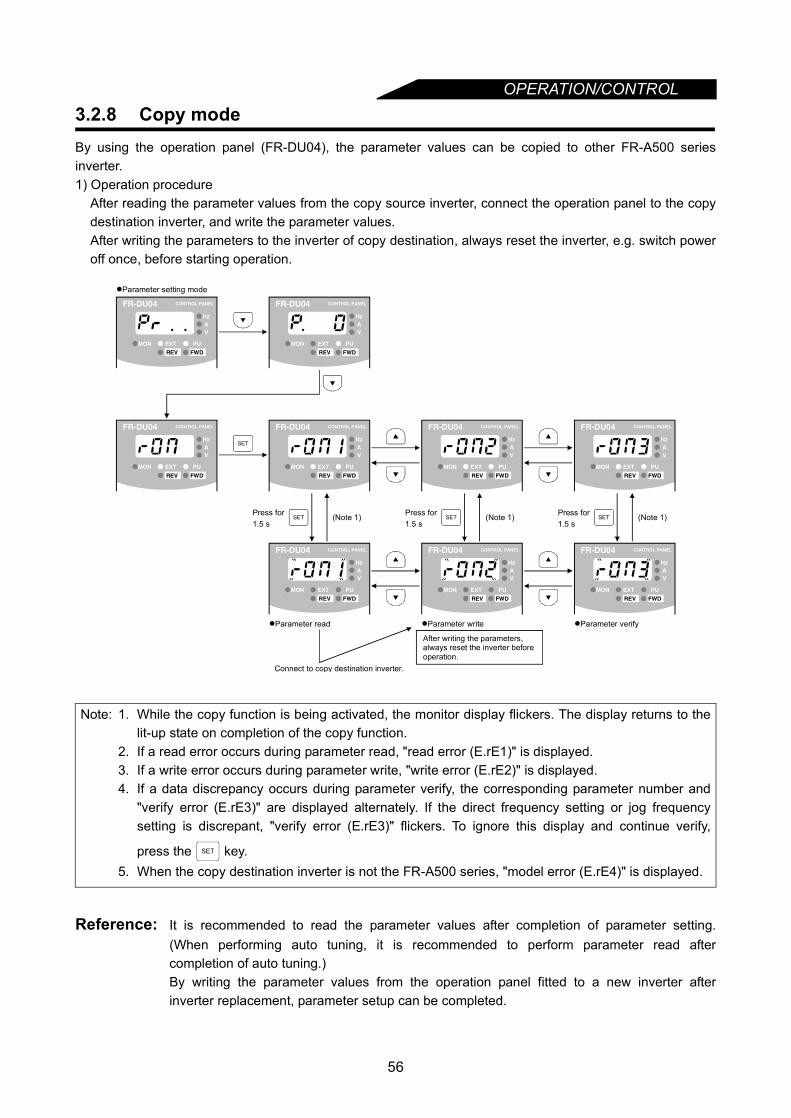
OPERATION/CONTROL
3.2.8 Copy modeBy using the operation panel (FR-DU04), the parameter values can be copied to other FR-A500 seriesinverter.1) Operation procedureAfter reading the parameter values from the copy source inverter, connect the operation panel to the copydestination inverter, and write the parameter values.After writing the parameters to the inverter of copy destination, always reset the inverter, e.g. switch poweroff once, before starting operation.
Reference: It is recommended to read the parameter values after completion of parameter setting.(When performing auto tuning, it is recommended to perform parameter read aftercompletion of auto tuning.)By writing the parameter values from the operation panel fitted to a new inverter afterinverter replacement, parameter setup can be completed.
Note: 1. While the copy function is being activated, the monitor display flickers. The display returns to thelit-up state on completion of the copy function.
2. If a read error occurs during parameter read, "read error (E.rE1)" is displayed.3. If a write error occurs during parameter write, "write error (E.rE2)" is displayed.4. If a data discrepancy occurs during parameter verify, the corresponding parameter number and
"verify error (E.rE3)" are displayed alternately. If the direct frequency setting or jog frequencysetting is discrepant, "verify error (E.rE3)" flickers. To ignore this display and continue verify,
press the key.5. When the copy destination inverter is not the FR-A500 series, "model error (E.rE4)" is displayed.
SET SET SET
SET
Connect to copy destination inverter.
Parameter setting mode
(Note 1) (Note 1) (Note 1)
Parameter read Parameter write Parameter verify
Press for 1.5 s
Press for 1.5 s
Press for 1.5 s
FR-DU04 CONTROL PANEL
Hz
MON EXT PU
AV
REV FWD
FR-DU04 CONTROL PANEL
Hz
MON EXT PU
AV
REV FWD
FR-DU04 CONTROL PANEL
Hz
MON EXT PU
AV
REV FWD
FR-DU04 CONTROL PANEL
Hz
MON EXT PU
AV
REV FWD
FR-DU04 CONTROL PANEL
Hz
MON EXT PU
AV
REV FWD
FR-DU04 CONTROL PANEL
Hz
MON EXT PU
AV
REV FWD
FR-DU04 CONTROL PANEL
Hz
MON EXT PU
AV
REV FWD
FR-DU04 CONTROL PANEL
Hz
MON EXT PU
AV
REV FWD
FR-DU04 CONTROL PANEL
Hz
MON EXT PU
AV
REV FWD
After writing the parameters, always reset the inverter before operation.
SET
56
OPERATION/CONTROL
3
3.3 Operation
3.3.1 Pre-operation checksBefore starting operation, check the following:
• SafetyPerform test operation after making sure that safety is ensured if the machine should become out ofcontrol.
• MachineMake sure that the machine is free of damage.
• ParametersSet the parameter values to match the operating machine system environment.
• Test operationPerform test operation and make sure that the machine operates safely under light load at a low frequency.After that, start operation.
57

OPERATION/CONTROL
3.3.2 External operation mode (Operation using external input signals)(1) Operation at 60Hz<Connection example>
For details of each terminal, refer to page 13 .
(2) External jog operation
Step Description Image
1
Power-on → Operation mode checkSwitch power on and make sure that the operation command indication "EXT" is lit.(If it is not lit, press the key to choose the operation mode and press the key to switch to external operation.)
2
StartTurn on the start switch (STF or STR).The operation status indication "FWD" or "REV" flickers.
3
Acceleration → Constant speedSlowly turn the potentiometer (frequency setting potentiometer) full clockwise.The frequency shown on the display increases gradually to 60.00Hz.
4
DecelerationSlowly turn the potentiometer (frequency setting potentiometer) full counterclockwise.The frequency shown on the display decreases gradually to 0.00Hz.The motor stops running.
5
StopTurn off the start switch (STF or STR).
Keep the start switch (STF or STR) on to perform operation, and switch it off to stop.1) Set Pr. 15 "jog frequency" and Pr. 16 "jog acceleration/deceleration" time.2) Set the external operation mode.3) Switch on the jog signal. Keep the start switch (STF or STR) on to perform
operation.Use any of Pr. 180 to Pr. 186 (input terminal function selection) to assign theterminal used for the jog signal.
<Connection example>
AU *
54
STFSTR
SD*Short terminals AU-SD for current input.Frequency setting
potentiometer0 to 10VDC
1025
Inverter
STFSTR
SD
Frequency setting by current inputFrequency setting by voltage input
4 to 20mADCCurrent input Inverter
MODE
ON
FR-DU04 CONTROL PANEL
Hz
MON EXT PU
AV
REV FWD
Note: The motor does not start if both the forward and reverserotation switches are turned on.If both switches are turned on during operation, the motordecelerates to a stop.
Reverserotation
Forwardrotation
FR-DU04 CONTROL PANEL
Hz
MON EXT PU
AV
REV FWD
FR-DU04 CONTROL PANEL
Hz
MON EXT PU
AV
REV FWD
FR-DU04 CONTROL PANEL
Hz
MON EXT PU
AV
REV FWD
OFF
Stop
Forwardrotation
Reverserotation
Inverter
STFSTR
SDJOG
58

OPERATION/CONTROL
3
3.3.3 PU operation mode (Operation using the operation panel (FR-DU04))
(1) Operation at 60HzWhile the motor is running, repeat the following steps 2 and 3 to vary the speed:
(2) PU jog operation
Hold down the or key to perform operation, and release it to stop.
1) Set Pr. 15 "jog frequency" and Pr. 16 "jog acceleration/deceleration".2) Select the PU jog operation. (Press the key to choose the operation mode and press the
key to switch to PU jog operation.)3) Hold down the or key to perform operation.
(If the motor remains stopped, check Pr. 13 "starting frequency". The motor will not start if its setting islower than the starting frequency.)
Step Description Image
1
Power-on → Operation mode checkSwitch power on and make sure that the operation commandindication "PU" is lit.(If it is not lit, press the key to choose the operation mode and press the key to switch to PU operation. )
2
Running frequency settingSet the running frequency to 60Hz.First, press the key to select the frequency setting mode. Then,press the key to change the setting, and press thekey to write the frequency
3
StartPress the or key.The motor starts running. The monitoring mode is automatically selected and the output frequency is displayed.
4
StopPress the key.The motor is decelerated to a stop.
MODE
ON
FR-DU04 CONTROL PANEL
Hz
MON EXT PU
AV
REV FWD
MODE
SET
(or)
FR-DU04 CONTROL PANEL
Hz
MON EXT PU
AV
REV FWD
FWD REVREVFWD (or)
FR-DU04 CONTROL PANEL
Hz
MON EXT PU
AV
REV FWD
STOPRESET
FR-DU04 CONTROL PANEL
Hz
MON EXT PU
AV
REV FWD
FWD REV
MODE
FWD REV
59

OPERATION/CONTROL
3.3.4 Combined operation mode(Operation using the external input signals and PU)When entering the start signal from outside the inverter (switch, relay, etc,) and setting the running frequency
from the PU (Pr. 79 = 3)The external frequency setting signals and the PU's FWD, REV and STOP keys are not accepted. (Note)
Note: The stop key is made valid when the Pr.75 "PU stop selection" value is set to any of 14 to 17.
Step Description Image
1
Power-onSwitch power on.
2
Operation mode selectionSet "3" in Pr. 79 "operation mode selection".The combined operation mode is selected and the operation statusindication "EXT" and "PU" are lit.
3
StartTurn on the start switch (STF or STR).
4
Running frequency settingUsing the parameter unit, set the running frequency to 60Hz.The operation command indication "REV" or "FWD" flickers.•Select the frequency setting mode and make step setting.
5
StopTurn off the start switch (STF or STR).The motor stops running.
ON
Flicker
Note: The motor does not start if both the forward and reverserotation switches are turned on. If both switches are turnedon during operation, the motor decelerates (when Pr. 250= "9999") to a stop.
ON
Reverserotation
Forwardrotation
FR-DU04 CONTROL PANEL
Hz
MON EXT PU
AV
REV FWD
Note: Step setting is the way of changing the frequency
consecutively by pressing the key.
Hold down the key to change the frequency.
<Step setting>
FR-DU04 CONTROL PANEL
Hz
MON EXT PU
AV
REV FWD
60
CHAPTER 4
PARAMETERSChapter 1
Chapter 2
Chapter 3
Chapter 4
Chapter 5
Chapter 6
Chapter 7
Chapter 8
This chapter explains the "parameters" for use of this product.The inverter is designed to perform simple variable-speedoperation with the factory settings of the parameters. Set thenecessary parameters according to the load and operationspecifications.Always read the instructions and other information before usingthe equipment.
4.1 Parameter Lists .....................................................624.2 Parameter Function Details ...................................71
Note: By making parameter settings, you can change the functions of contact inputterminals RL, RM, RH, RT, AU, JOG, CS and open collector output terminalsRUN, SU, IPF, OL, FU. Therefore, signal names corresponding to the functionsare used in the description of this chapter (except in the wiring examples). Notethat they are not terminal names.Note: The settings in parenthesis refer to the "EC" version default settings.
61
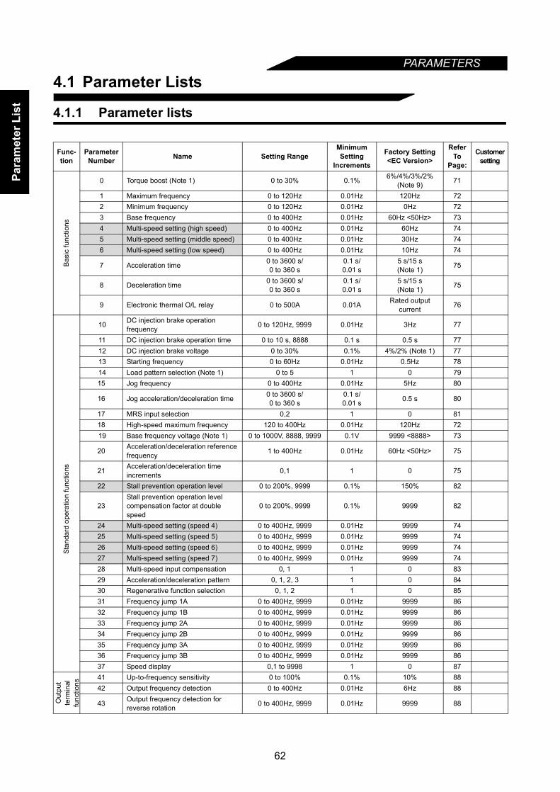
Para
met
er L
ist
PARAMETERS
4.1 Parameter Lists
4.1.1 Parameter lists
Func-tion
Parameter Number Name Setting Range
Minimum Setting
Increments
Factory Setting<EC Version>
Refer To
Page:
Customersetting
Basi
c fu
nctio
ns
0 Torque boost (Note 1) 0 to 30% 0.1% 6%/4%/3%/2%(Note 9) 71
1 Maximum frequency 0 to 120Hz 0.01Hz 120Hz 722 Minimum frequency 0 to 120Hz 0.01Hz 0Hz 723 Base frequency 0 to 400Hz 0.01Hz 60Hz <50Hz> 734 Multi-speed setting (high speed) 0 to 400Hz 0.01Hz 60Hz 745 Multi-speed setting (middle speed) 0 to 400Hz 0.01Hz 30Hz 746 Multi-speed setting (low speed) 0 to 400Hz 0.01Hz 10Hz 74
7 Acceleration time 0 to 3600 s/0 to 360 s
0.1 s/0.01 s
5 s/15 s(Note 1) 75
8 Deceleration time 0 to 3600 s/0 to 360 s
0.1 s/0.01 s
5 s/15 s(Note 1) 75
9 Electronic thermal O/L relay 0 to 500A 0.01A Rated output current 76
Stan
dard
ope
ratio
n fu
nctio
ns
10 DC injection brake operation frequency 0 to 120Hz, 9999 0.01Hz 3Hz 77
11 DC injection brake operation time 0 to 10 s, 8888 0.1 s 0.5 s 7712 DC injection brake voltage 0 to 30% 0.1% 4%/2% (Note 1) 7713 Starting frequency 0 to 60Hz 0.01Hz 0.5Hz 7814 Load pattern selection (Note 1) 0 to 5 1 0 7915 Jog frequency 0 to 400Hz 0.01Hz 5Hz 80
16 Jog acceleration/deceleration time 0 to 3600 s/0 to 360 s
0.1 s/0.01 s 0.5 s 80
17 MRS input selection 0,2 1 0 8118 High-speed maximum frequency 120 to 400Hz 0.01Hz 120Hz 7219 Base frequency voltage (Note 1) 0 to 1000V, 8888, 9999 0.1V 9999 <8888> 73
20 Acceleration/deceleration reference frequency 1 to 400Hz 0.01Hz 60Hz <50Hz> 75
21 Acceleration/deceleration time increments 0,1 1 0 75
22 Stall prevention operation level 0 to 200%, 9999 0.1% 150% 82
23Stall prevention operation level compensation factor at double speed
0 to 200%, 9999 0.1% 9999 82
24 Multi-speed setting (speed 4) 0 to 400Hz, 9999 0.01Hz 9999 7425 Multi-speed setting (speed 5) 0 to 400Hz, 9999 0.01Hz 9999 7426 Multi-speed setting (speed 6) 0 to 400Hz, 9999 0.01Hz 9999 7427 Multi-speed setting (speed 7) 0 to 400Hz, 9999 0.01Hz 9999 7428 Multi-speed input compensation 0, 1 1 0 8329 Acceleration/deceleration pattern 0, 1, 2, 3 1 0 8430 Regenerative function selection 0, 1, 2 1 0 8531 Frequency jump 1A 0 to 400Hz, 9999 0.01Hz 9999 8632 Frequency jump 1B 0 to 400Hz, 9999 0.01Hz 9999 8633 Frequency jump 2A 0 to 400Hz, 9999 0.01Hz 9999 8634 Frequency jump 2B 0 to 400Hz, 9999 0.01Hz 9999 8635 Frequency jump 3A 0 to 400Hz, 9999 0.01Hz 9999 8636 Frequency jump 3B 0 to 400Hz, 9999 0.01Hz 9999 8637 Speed display 0,1 to 9998 1 0 87
Out
put
term
inal
func
tions
41 Up-to-frequency sensitivity 0 to 100% 0.1% 10% 8842 Output frequency detection 0 to 400Hz 0.01Hz 6Hz 88
43 Output frequency detection for reverse rotation 0 to 400Hz, 9999 0.01Hz 9999 88
62
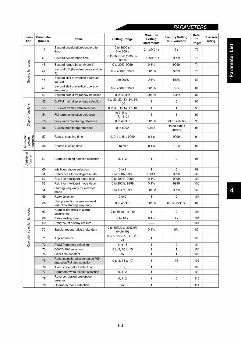
Para
met
er L
ist
PARAMETERS
4
Sec
ond
func
tions
44 Second acceleration/deceleration time
0 to 3600 s/0 to 360 s 0.1 s/0.01 s 5 s 75
45 Second deceleration time 0 to 3600 s/0 to 360 s, 9999 0.1 s/0.01 s 9999 75
46 Second torque boost (Note 1) 0 to 30%, 9999 0.1% 9999 71
47 Second V/F (base frequency) (Note 1) 0 to 400Hz, 9999 0.01Hz 9999 73
48 Second stall prevention operation current 0 to 200% 0.1% 150% 89
49 Second stall prevention operation frequency 0 to 400Hz, 9999 0.01Hz 0Hz 89
50 Second output frequency detection 0 to 400Hz 0.01Hz 30Hz 88
Dis
play
func
tions
52 DU/PU main display data selection 0 to 20, 22, 23, 24, 25, 100 1 0 90
53 PU level display data selection 0 to 3, 5 to 14, 17, 18 1 1 90
54 FM terminal function selection 1 to 3, 5 to 14,17, 18, 21 1 1 90
55 Frequency monitoring reference 0 to 400Hz 0.01Hz 60Hz <50Hz> 93
56 Current monitoring reference 0 to 500A 0.01A Rated output current 93
Auto
mat
icre
star
tfu
nctio
ns 57 Restart coasting time 0, 0.1 to 5 s, 9999 0.1 s 9999 94
58 Restart cushion time 0 to 60 s 0.1 s 1.0 s 94
Add
ition
alfu
nctio
n
59 Remote setting function selection 0, 1, 2 1 0 96
Ope
ratio
n se
lect
ion
func
tions
60 Intelligent mode selection 0 to 8 1 0 9861 Reference I for intelligent mode 0 to 500A, 9999 0.01A 9999 10062 Ref. I for intelligent mode accel. 0 to 200%, 9999 0.1% 9999 10063 Ref. I for intelligent mode decel. 0 to 200%, 9999 0.1% 9999 100
64 Starting frequency for elevator mode 0 to 10Hz, 9999 0.01Hz 9999 100
65 Retry selection 0 to 5 1 0 101
66 Stall prevention operation level reduction starting frequency 0 to 400Hz 0.01Hz 60Hz <50Hz> 82
67 Number of retries at alarm occurrence 0 to 10,101 to 110 1 0 101
68 Retry waiting time 0 to 10 s 0.1 s 1 s 10169 Retry count display erasure 0 0 101
70 Special regenerative brake duty 0 to 15%/0 to 30%/0% (Note 10) 0.1% 0% 85
71 Applied motor 0 to 8, 13 to 18, 20, 23, 24 1 0 103
72 PWM frequency selection 0 to 15 1 2 10473 0-5V/0-10V selection 0 to 5, 10 to 15 1 1 10574 Filter time constant 0 to 8 1 1 106
75 Reset selection/disconnected PU detection/PU stop selection 0 to 3, 14 to 17 1 14 106
76 Alarm code output selection 0, 1, 2, 3 1 0 10877 Parameter write disable selection 0, 1, 2 1 0 109
78 Reverse rotation prevention selection 0, 1, 2 1 0 110
79 Operation mode selection 0 to 8 1 0 111
Func-tion
Parameter Number Name Setting Range
Minimum Setting
Increments
Factory Setting<EC Version>
Refer To
Page:
Customersetting
63
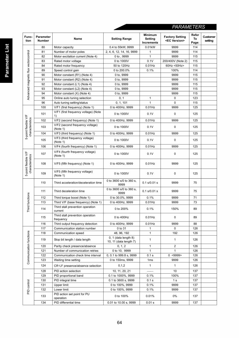
Para
met
er L
ist
PARAMETERS
Advan
ced
mag
netic
flux
vec
torc
ontro
l
80 Motor capacity 0.4 to 55kW, 9999 0.01kW 9999 11481 Number of motor poles 2, 4, 6, 12, 14, 16, 9999 1 9999 11482 Motor excitation current (Note 4) 0 to , 9999 1 9999 11583 Rated motor voltage 0 to 1000V 0.1V 200/400V (Note 2) 11584 Rated motor frequency 50 to 120Hz 0.01Hz 60Hz <50Hz> 11589 Speed control gain 0 to 200.0% 0.1% 100% 11490 Motor constant (R1) (Note 4) 0 to, 9999 9999 11591 Motor constant (R2) (Note 4) 0 to, 9999 9999 11592 Motor constant (L1) (Note 4) 0 to, 9999 9999 11593 Motor constant (L2) (Note 4) 0 to, 9999 9999 11594 Motor constant (X) (Note 4) 0 to, 9999 9999 11595 Online auto tuning selection 0, 1 1 0 12396 Auto tuning setting/status 0, 1, 101 1 0 115
5-po
int f
lexi
ble
V/F
char
acte
ristic
s
100 V/F1 (first frequency) (Note 1) 0 to 400Hz, 9999 0.01Hz 9999 125
101 V/F1 (first frequency voltage) (Note 1) 0 to 1000V 0.1V 0 125
102 V/F2 (second frequency) (Note 1) 0 to 400Hz, 9999 0.01Hz 9999 125
103 V/F2 (second frequency voltage) (Note 1) 0 to 1000V 0.1V 0 125
104 V/F3 (third frequency) (Note 1) 0 to 400Hz, 9999 0.01Hz 9999 125
105 V/F3 (third frequency voltage) (Note 1) 0 to 1000V 0.1V 0 125
106 V/F4 (fourth frequency) (Note 1) 0 to 400Hz, 9999 0.01Hz 9999 125
5-po
int f
lexi
ble
V/F
char
acte
ristic
s 107 V/F4 (fourth frequency voltage)(Note 1) 0 to 1000V 0.1V 0 125
108 V/F5 (fifth frequency) (Note 1) 0 to 400Hz, 9999 0.01Hz 9999 125
109 V/F5 (fifth frequency voltage)(Note 1) 0 to 1000V 0.1V 0 125
Third
func
tions
110 Third acceleration/deceleration time 0 to 3600 s/0 to 360 s, 9999 0.1 s/0.01 s 9999 75
111 Third deceleration time 0 to 3600 s/0 to 360 s, 9999 0.1 s/0.01 s 9999 75
112 Third torque boost (Note 1) 0 to 30.0%, 9999 0.1% 9999 71113 Third V/F (base frequency) (Note 1) 0 to 400Hz, 9999 0.01Hz 9999 73
114 Third stall prevention operation current 0 to 200% 0.1% 150% 89
115 Third stall prevention operation frequency 0 to 400Hz 0.01Hz 0 89
116 Third output frequency detection 0 to 400Hz, 9999 0.01Hz 9999 88
Com
mun
icat
ion
func
tions
117 Communication station number 0 to 31 1 0 126118 Communication speed 48, 96, 192 1 192 126
119 Stop bit length / data length 0, 1 (data length 8)10, 11 (data length 7) 1 1 126
120 Parity check presence/absence 0, 1, 2 1 2 126121 Number of communication retries 0 to 10, 9999 1 1 126122 Communication check time interval 0, 0.1 to 999.8 s, 9999 0.1 s 0 <9999> 126123 Waiting time setting 0 to 150ms, 9999 1ms 9999 126
124 CR⋅LF presence/absence selection 0,1,2 1 1 126
PID
con
trol
128 PID action selection 10, 11, 20, 21 10 137129 PID proportional band 0.1 to 1000%, 9999 0.1% 100% 137130 PID integral time 0.1 to 3600 s, 9999 0.1 s 1 s 137131 Upper limit 0 to 100%, 9999 0.1% 9999 137132 Lower limit 0 to 100%, 9999 0.1% 9999 137
133 PID action set point for PU operation 0 to 100% 0.01% 0% 137
134 PID differential time 0.01 to 10.00 s, 9999 0.01 s 9999 137
Func-tion
Parameter Number Name Setting Range
Minimum Setting
Increments
Factory Setting<EC Version>
Refer To
Page:
Customersetting
64

Para
met
er L
ist
PARAMETERS
4
Com
mer
cial
pow
er s
uppl
y-in
verte
r sw
itcho
ver
135Commercial power supply-inverter switchover sequence output terminal selection
0, 1 1 0 144
136 MC switchover interlock time 0 to 100.0 s 0.1 s 1.0 s 144137 Start waiting time 0 to 100.0 s 0.1 s 0.5 s 144
138Commercial power supply-inverter switchover selection at alarm occurrence
0, 1 1 0 144
139 Automatic inverter-commercial power supply switchover frequency 0 to 60.00Hz, 9999 0.01Hz 9999 144
Bac
klas
h
140 Backlash acceleration stopping frequency (Note 7) 0 to 400Hz 0.01Hz 1.00Hz 84
141 Backlash acceleration stopping time (Note 7) 0 to 360 s 0.1 s 0.5 s 84
142 Backlash deceleration stopping frequency (Note 7) 0 to 400Hz 0.01Hz 1.00Hz 84
143 Backlash deceleration stopping time (Note 7) 0 to 360 s 0.1 s 0.5 s 84
Dis
play
144 Speed setting switchover 0, 2, 4, 6, 8, 10, 102,104, 106, 108, 110 1 4 87
Addi
tiona
lfu
nctio
ns
145 PU display language selection
148 Stall prevention operation level at 0V input 0 to 200% 0.1% 150% 82
149 Stall prevention operation level at 10V input 0 to 200% 0.1% 200% 82
Cur
rent
dete
ctio
n 152 Zero current detection level 0 to 200.0% 0.1% 5.0% 150
153 Zero current detection period 0 to 1 s 0.01 s 0.5 s 150
Cur
rent
dete
ctio
n 150 Output current detection level 0 to 200% 0.1% 150% 149
151 Output current detection period 0 to 10 s 0.1 s 0 149
Sub
func
tions
154 Voltage reduction selection during stall prevention operation 0, 1 1 1 82
155 RT signal activated condition 0, 10 1 0 151156 Stall prevention operation selection 0 to 31, 100, 101 1 0 151157 OL signal waiting time 0 to 25 s, 9999 0.1 s 0 153
158 AM terminal function selection 1 to 3, 5 to 14, 17, 18, 21 1 1 90
Addi
tiona
lfu
nctio
n
160 User group read selection 0, 1, 10, 11 1 0 154
Aut
omat
ic re
star
t af
ter i
nsta
ntan
eous
pow
er fa
ilure
162 Automatic restart after instantaneous power failure selection 0, 1 1 0 94
163 First cushion time for restart 0 to 20 s 0.1 s 0 s 94164 First cushion voltage for restart 0 to 100% 0.1% 0% 94
165 Restart stall prevention operation level 0 to 200% 0.1% 150% 94
Addi
tiona
l fu
nctio
ns 168Maker setting parameters. Do not make setting.
169
Initi
alm
onito
r 170 Watt-hour meter clear 0 0 155
171 Actual operation hour meter clear 0 0 155
Use
r fun
ctio
ns 173 User group 1 registration 0 to 999 1 0 154174 User group 1 deletion 0 to 999, 9999 1 0 154175 User group 2 registration 0 to 999 1 0 154
176 User group 2 deletion 0 to 999, 9999 1 0 154
Func-tion
Parameter Number Name Setting Range
Minimum Setting
Increments
Factory Setting<EC Version>
Refer To
Page:
Customersetting
65

Para
met
er L
ist
PARAMETERS
Termin
al a
ssig
nmen
t fun
ctio
ns
180 RL terminal function selection
0 to 99, 9999
1 0 155181 RM terminal function selection 1 1 155182 RH terminal function selection 1 2 155183 RT terminal function selection 1 3 155184 AU terminal function selection 1 4 155185 JOG terminal function selection 1 5 155186 CS terminal function selection 1 6 155190 RUN terminal function selection
0 to 199, 9999
1 0 158191 SU terminal function selection 1 1 158192 IPF terminal function selection 1 2 158193 OL terminal function selection 1 3 158194 FU terminal function selection 1 4 158195 A, B, C terminal function selection 1 99 158
Addi
ti-on
alfu
nctio
199 User's initial value setting 0 to 999, 9999 1 0 160
Pro
gram
med
ope
ratio
n
200 Programmed operation minute/second selection
0, 2: Minute, second1, 3: Hour, minute 1 0 161
201 to 210 Program set 11 to 10
0-2: Rotation direction0-400, 99990-99.59: Time
10.1Hz
Minute orsecond
09999
0161
211 to 220 Program set11 to 20
0-2: Rotation direction0-400, 9999: Frequency
10.1Hz
Minute orsecond
09999
0161
221 to 230 Program set 321 to 30
0-2: Rotation direction0-400, 9999: Frequency0-99.59: Time
10.1Hz
Minute orsecond
09999
0161
231 Timer setting 0 to 99.59 0 161
Mul
ti-sp
eed
oper
atio
n
232 Multi-speed setting (speed 8) 0 to 400Hz, 9999 0.01Hz 9999 74233 Multi-speed setting (speed 9) 0 to 400Hz, 9999 0.01Hz 9999 74234 Multi-speed setting (speed 10) 0 to 400Hz, 9999 0.01Hz 9999 74235 Multi-speed setting (speed 11) 0 to 400Hz, 9999 0.01Hz 9999 74236 Multi-speed setting (speed 12) 0 to 400Hz, 9999 0.01Hz 9999 74237 Multi-speed setting (speed 13) 0 to 400Hz, 9999 0.01Hz 9999 74238 Multi-speed setting (speed 14) 0 to 400Hz, 9999 0.01Hz 9999 74239 Multi-speed setting (speed 15) 0 to 400Hz, 9999 0.01Hz 9999 74
Sub
func
tions 240 Soft-PWM setting 0, 1 1 1 104
244 Cooling fan operation selection 0, 1 1 1 165
Stop
sel
ectio
nfu
nctio
ns
250 Stop selection 0 to 100 s, 9999 0.1 s 9999 166
Add
ition
alfu
nctio
n 251 Output phase failure protection selection 0,1 1 1 167
252 Override bias 0 to 200% 0.1% 50% 167
253 Override gain 0 to 200% 0.1% 150% 167
Func-tion
Parameter Number Name Setting Range
Minimum Setting
Increments
Factory Setting<EC Version>
Refer To
Page:
Customersetting
66
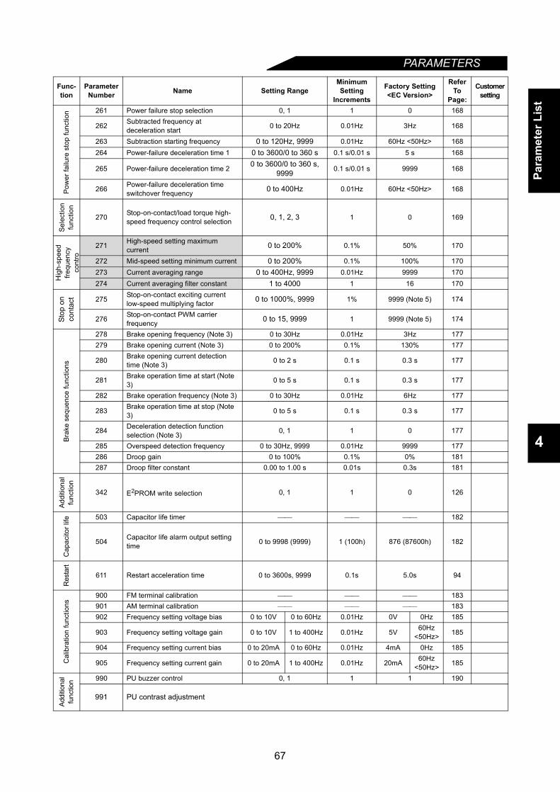
Para
met
er L
ist
PARAMETERS
4
Pow
er fa
ilure
sto
p fu
nctio
n 261 Power failure stop selection 0, 1 1 0 168
262 Subtracted frequency at deceleration start 0 to 20Hz 0.01Hz 3Hz 168
263 Subtraction starting frequency 0 to 120Hz, 9999 0.01Hz 60Hz <50Hz> 168264 Power-failure deceleration time 1 0 to 3600/0 to 360 s 0.1 s/0.01 s 5 s 168
265 Power-failure deceleration time 2 0 to 3600/0 to 360 s, 9999 0.1 s/0.01 s 9999 168
266 Power-failure deceleration time switchover frequency 0 to 400Hz 0.01Hz 60Hz <50Hz> 168
Sele
ctio
nfu
nctio
n
270 Stop-on-contact/load torque high-speed frequency control selection 0, 1, 2, 3 1 0 169
Hig
h-sp
eed
frequ
ency
cont
ro
271 High-speed setting maximum current 0 to 200% 0.1% 50% 170
272 Mid-speed setting minimum current 0 to 200% 0.1% 100% 170273 Current averaging range 0 to 400Hz, 9999 0.01Hz 9999 170274 Current averaging filter constant 1 to 4000 1 16 170
Stop
on
cont
act 275 Stop-on-contact exciting current
low-speed multiplying factor 0 to 1000%, 9999 1% 9999 (Note 5) 174
276 Stop-on-contact PWM carrier frequency 0 to 15, 9999 1 9999 (Note 5) 174
Brak
e se
quen
ce fu
nctio
ns
278 Brake opening frequency (Note 3) 0 to 30Hz 0.01Hz 3Hz 177279 Brake opening current (Note 3) 0 to 200% 0.1% 130% 177
280 Brake opening current detection time (Note 3) 0 to 2 s 0.1 s 0.3 s 177
281 Brake operation time at start (Note 3) 0 to 5 s 0.1 s 0.3 s 177
282 Brake operation frequency (Note 3) 0 to 30Hz 0.01Hz 6Hz 177
283 Brake operation time at stop (Note 3) 0 to 5 s 0.1 s 0.3 s 177
284 Deceleration detection function selection (Note 3) 0, 1 1 0 177
285 Overspeed detection frequency 0 to 30Hz, 9999 0.01Hz 9999 177286 Droop gain 0 to 100% 0.1% 0% 181287 Droop filter constant 0.00 to 1.00 s 0.01s 0.3s 181
Addi
tiona
lfu
nctio
n
342 E2PROM write selection 0, 1 1 0 126
Cap
acito
r life 503 Capacitor life timer 182
504 Capacitor life alarm output setting time 0 to 9998 (9999) 1 (100h) 876 (87600h) 182
Res
tart
611 Restart acceleration time 0 to 3600s, 9999 0.1s 5.0s 94
Cal
ibra
tion
func
tions
900 FM terminal calibration 183901 AM terminal calibration 183902 Frequency setting voltage bias 0 to 10V 0 to 60Hz 0.01Hz 0V 0Hz 185
903 Frequency setting voltage gain 0 to 10V 1 to 400Hz 0.01Hz 5V 60Hz<50Hz> 185
904 Frequency setting current bias 0 to 20mA 0 to 60Hz 0.01Hz 4mA 0Hz 185
905 Frequency setting current gain 0 to 20mA 1 to 400Hz 0.01Hz 20mA 60Hz<50Hz> 185
Addi
tiona
lfu
nctio
n 990 PU buzzer control 0, 1 1 1 190
991 PU contrast adjustment
Func-tion
Parameter Number Name Setting Range
Minimum Setting
Increments
Factory Setting<EC Version>
Refer To
Page:
Customersetting
67
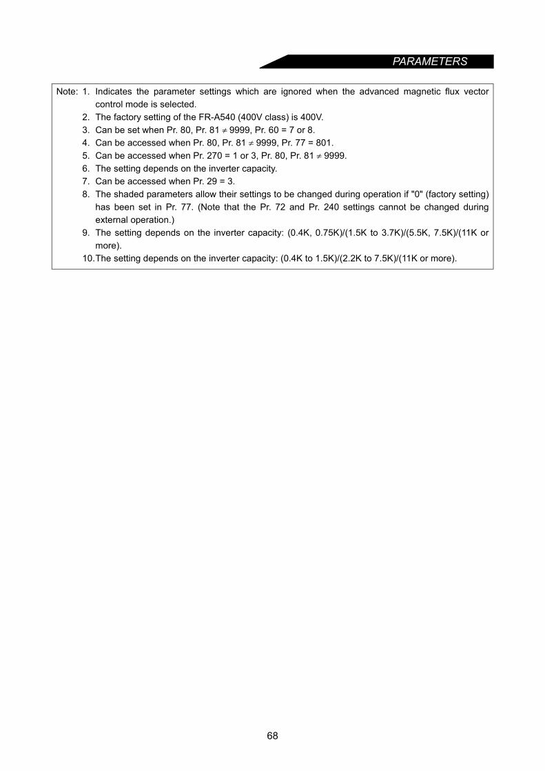
PARAMETERS
Note: 1. Indicates the parameter settings which are ignored when the advanced magnetic flux vectorcontrol mode is selected.
2. The factory setting of the FR-A540 (400V class) is 400V.3. Can be set when Pr. 80, Pr. 81 ≠ 9999, Pr. 60 = 7 or 8.4. Can be accessed when Pr. 80, Pr. 81 ≠ 9999, Pr. 77 = 801.5. Can be accessed when Pr. 270 = 1 or 3, Pr. 80, Pr. 81 ≠ 9999.6. The setting depends on the inverter capacity.7. Can be accessed when Pr. 29 = 3.8. The shaded parameters allow their settings to be changed during operation if "0" (factory setting)
has been set in Pr. 77. (Note that the Pr. 72 and Pr. 240 settings cannot be changed duringexternal operation.)
9. The setting depends on the inverter capacity: (0.4K, 0.75K)/(1.5K to 3.7K)/(5.5K, 7.5K)/(11K ormore).
10.The setting depends on the inverter capacity: (0.4K to 1.5K)/(2.2K to 7.5K)/(11K or more).
68
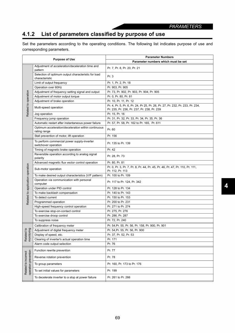
PARAMETERS
4
4.1.2 List of parameters classified by purpose of useSet the parameters according to the operating conditions. The following list indicates purpose of use andcorresponding parameters.
Purpose of UseParameter Numbers
Parameter numbers which must be set
Rel
ated
to o
pera
tion
Adjustment of acceleration/deceleration time and pattern Pr. 7, Pr. 8, Pr. 20, Pr. 21
Selection of optimum output characteristic for load characteristic Pr. 3
Limit of output frequency Pr. 1, Pr. 2, Pr. 18Operation over 60Hz Pr. 903, Pr. 905Adjustment of frequency setting signal and output Pr. 73, Pr. 902, Pr. 903, Pr. 904, Pr. 905Adjustment of motor output torque Pr. 0, Pr. 80, Pr. 81Adjustment of brake operation Pr. 10, Pr. 11, Pr. 12
Multi-speed operation Pr. 4, Pr. 5, Pr. 6, Pr. 24, Pr 25, Pr. 26, Pr. 27, Pr. 232, Pr. 233, Pr. 234, Pr. 235, Pr. 236, Pr. 237, Pr. 238, Pr. 239
Jog operation Pr. 15, Pr. 16Frequency jump operation Pr. 31, Pr. 32, Pr. 33, Pr. 34, Pr. 35, Pr. 36Automatic restart after instantaneous power failure Pr. 57, Pr. 58, Pr. 162 to Pr. 165, Pr. 611Optimum acceleration/deceleration within continuous rating range Pr. 60
Stall prevention of motor, lift operation Pr. 156
Rel
ated
to a
pplic
atio
n op
erat
ion
To perform commercial power supply-inverter switchover operation Pr. 135 to Pr. 139
Timing of magnetic brake operation Pr. 42Reversible operation according to analog signal polarity Pr. 28, Pr. 73
Advanced magnetic flux vector control operation Pr. 80, Pr. 81
Sub-motor operation Pr. 0, Pr. 3, Pr. 7, Pr. 8, Pr. 44, Pr. 45, Pr. 46, Pr. 47, Pr. 110, Pr. 111, Pr. 112, Pr. 113
To make desired output characteristics (V/F pattern) Pr. 100 to Pr. 109Operation via communication with personal computer Pr. 117 to Pr. 124, Pr. 342
Operation under PID control Pr. 128 to Pr. 134To make backlash compensation Pr. 140 to Pr. 143To detect current Pr. 150 to Pr. 153Programmed operation Pr. 200 to Pr. 231High-speed frequency control operation Pr. 271 to Pr. 274To exercise stop-on-contact control Pr. 275, Pr. 276To exercise droop control Pr. 286, Pr. 287To suppress noise Pr. 72, Pr. 240
Rel
ated
tom
onito
ring
Calibration of frequency meter Pr. 54,Pr. 55, Pr. 56, Pr. 158, Pr. 900, Pr. 901Adjustment of digital frequency meter Pr. 54,Pr. 55, Pr. 56, Pr. 900Display of speed, etc. Pr. 37, Pr. 52, Pr. 53Clearing of inverter's actual operation time Pr. 171Alarm code output selection Pr. 76
Rel
ated
to in
corre
ctop
erat
ion
prev
entio
n Function rewrite prevention Pr. 77
Reverse rotation prevention Pr. 78
To group parameters Pr. 160, Pr. 173 to Pr. 176
To set initial values for parameters Pr. 199
To decelerate inverter to a stop at power failure Pr. 261 to Pr. 266
69
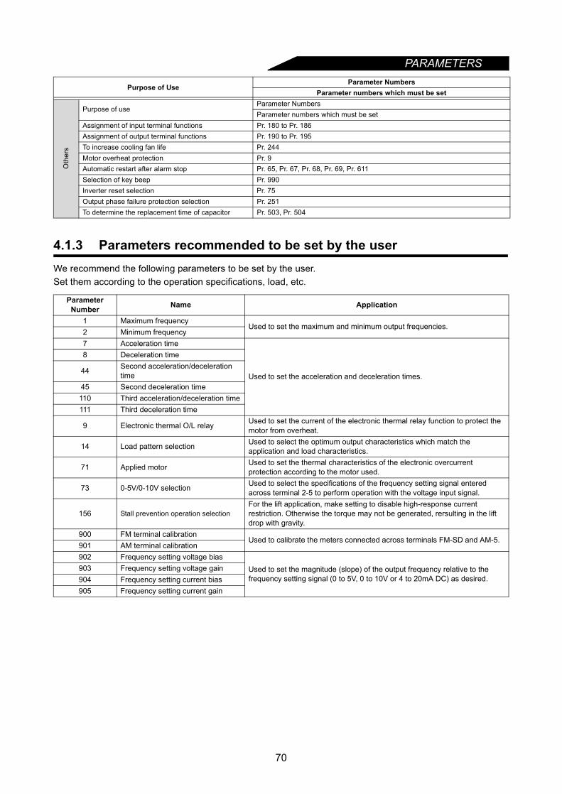
PARAMETERS
4.1.3 Parameters recommended to be set by the userWe recommend the following parameters to be set by the user.Set them according to the operation specifications, load, etc.
Oth
ers
Purpose of useParameter NumbersParameter numbers which must be set
Assignment of input terminal functions Pr. 180 to Pr. 186Assignment of output terminal functions Pr. 190 to Pr. 195To increase cooling fan life Pr. 244Motor overheat protection Pr. 9Automatic restart after alarm stop Pr. 65, Pr. 67, Pr. 68, Pr. 69, Pr. 611Selection of key beep Pr. 990Inverter reset selection Pr. 75Output phase failure protection selection Pr. 251To determine the replacement time of capacitor Pr. 503, Pr. 504
Parameter Number Name Application
1 Maximum frequencyUsed to set the maximum and minimum output frequencies.
2 Minimum frequency7 Acceleration time
Used to set the acceleration and deceleration times.
8 Deceleration time
44 Second acceleration/deceleration time
45 Second deceleration time110 Third acceleration/deceleration time111 Third deceleration time
9 Electronic thermal O/L relay Used to set the current of the electronic thermal relay function to protect the motor from overheat.
14 Load pattern selection Used to select the optimum output characteristics which match the application and load characteristics.
71 Applied motor Used to set the thermal characteristics of the electronic overcurrent protection according to the motor used.
73 0-5V/0-10V selection Used to select the specifications of the frequency setting signal entered across terminal 2-5 to perform operation with the voltage input signal.
156 Stall prevention operation selectionFor the lift application, make setting to disable high-response current restriction. Otherwise the torque may not be generated, rersulting in the lift drop with gravity.
900 FM terminal calibrationUsed to calibrate the meters connected across terminals FM-SD and AM-5.
901 AM terminal calibration902 Frequency setting voltage bias
Used to set the magnitude (slope) of the output frequency relative to the frequency setting signal (0 to 5V, 0 to 10V or 4 to 20mA DC) as desired.
903 Frequency setting voltage gain904 Frequency setting current bias905 Frequency setting current gain
Purpose of UseParameter Numbers
Parameter numbers which must be set
70
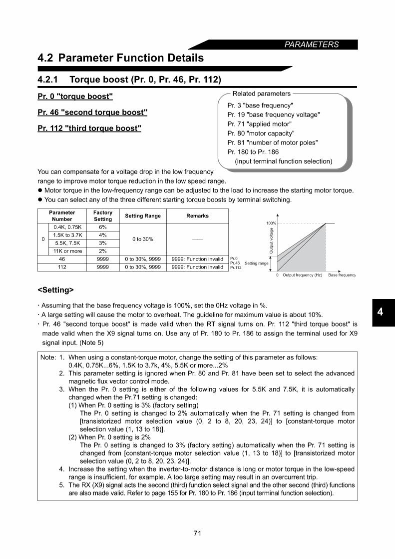
71
PARAMETERS
4
4.2 Parameter Function Details
4.2.1 Torque boost (Pr. 0, Pr. 46, Pr. 112)
Pr. 0 "torque boost"
Pr. 46 "second torque boost"
Pr. 112 "third torque boost"
You can compensate for a voltage drop in the low frequencyrange to improve motor torque reduction in the low speed range. Motor torque in the low-frequency range can be adjusted to the load to increase the starting motor torque. You can select any of the three different starting torque boosts by terminal switching.
<Setting>
Assuming that the base frequency voltage is 100%, set the 0Hz voltage in %. A large setting will cause the motor to overheat. The guideline for maximum value is about 10%. Pr. 46 "second torque boost" is made valid when the RT signal turns on. Pr. 112 "third torque boost" is
made valid when the X9 signal turns on. Use any of Pr. 180 to Pr. 186 to assign the terminal used for X9signal input. (Note 5)
Parameter Number
Factory Setting Setting Range Remarks
0
0.4K, 0.75K 6%
0 to 30%
1.5K to 3.7K 4%5.5K, 7.5K 3%
11K or more 2%46 9999 0 to 30%, 9999 9999: Function invalid112 9999 0 to 30%, 9999 9999: Function invalid
Note: 1. When using a constant-torque motor, change the setting of this parameter as follows:0.4K, 0.75K...6%, 1.5K to 3.7k, 4%, 5.5K or more...2%
2. This parameter setting is ignored when Pr. 80 and Pr. 81 have been set to select the advancedmagnetic flux vector control mode.
3. When the Pr. 0 setting is either of the following values for 5.5K and 7.5K, it is automaticallychanged when the Pr.71 setting is changed:(1) When Pr. 0 setting is 3% (factory setting)
The Pr. 0 setting is changed to 2% automatically when the Pr. 71 setting is changed from[transistorized motor selection value (0, 2 to 8, 20, 23, 24)] to [constant-torque motorselection value (1, 13 to 18)].
(2) When Pr. 0 setting is 2%The Pr. 0 setting is changed to 3% (factory setting) automatically when the Pr. 71 setting ischanged from [constant-torque motor selection value (1, 13 to 18)] to [transistorized motorselection value (0, 2 to 8, 20, 23, 24)].
4. Increase the setting when the inverter-to-motor distance is long or motor torque in the low-speedrange is insufficient, for example. A too large setting may result in an overcurrent trip.
5. The RX (X9) signal acts the second (third) function select signal and the other second (third) functionsare also made valid. Refer to page 155 for Pr. 180 to Pr. 186 (input terminal function selection).
Pr. 3 "base frequency"Pr. 19 "base frequency voltage"Pr. 71 "applied motor"Pr. 80 "motor capacity"Pr. 81 "number of motor poles"Pr. 180 to Pr. 186 (input terminal function selection)
Related parameters
Pr.0Pr.46
0
100%
Base frequencyO
utp
ut
vo
lta
ge
Setting range
Output frequency (Hz)
Pr.112
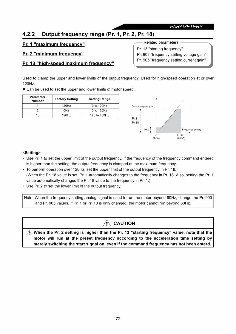
72
PARAMETERS4.2.2 Output frequency range (Pr. 1, Pr. 2, Pr. 18)
Pr. 1 "maximum frequency"
Pr. 2 "minimum frequency"
Pr. 18 "high-speed maximum frequency"
Used to clamp the upper and lower limits of the output frequency. Used for high-speed operation at or over120Hz. Can be used to set the upper and lower limits of motor speed.
<Setting>• Use Pr. 1 to set the upper limit of the output frequency. If the frequency of the frequency command entered
is higher than the setting, the output frequency is clamped at the maximum frequency.• To perform operation over 120Hz, set the upper limit of the output frequency in Pr. 18.
(When the Pr. 18 value is set, Pr. 1 automatically changes to the frequency in Pr. 18. Also, setting the Pr. 1value automatically changes the Pr. 18 value to the frequency in Pr. 1.)
• Use Pr. 2 to set the lower limit of the output frequency.
Parameter Number Factory Setting Setting Range
1 120Hz 0 to 120Hz2 0Hz 0 to 120Hz
18 120Hz 120 to 400Hz
Note: When the frequency setting analog signal is used to run the motor beyond 60Hz, change the Pr. 903and Pr. 905 values. If Pr. 1 or Pr. 18 is only changed, the motor cannot run beyond 60Hz.
CAUTION
When the Pr. 2 setting is higher than the Pr. 13 "starting frequency" value, note that themotor will run at the preset frequency according to the acceleration time setting bymerely switching the start signal on, even if the command frequency has not been enterd.
Related parametersPr. 13 "starting frequency"Pr. 903 "frequency setting voltage gain"Pr. 905 "frequency setting current gain"
Pr.1
Pr.2
5,10V0
Frequency setting
Output frequency (Hz)
(20mA)(4mA)
Pr.18
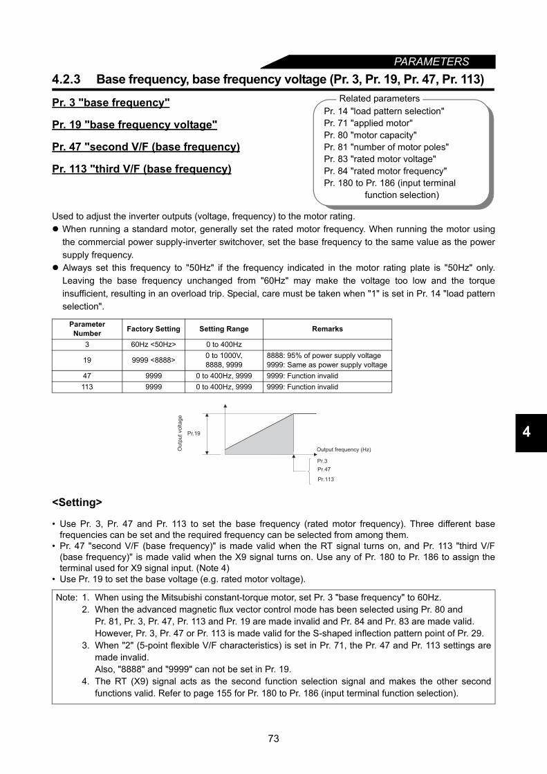
73
PARAMETERS
4
4.2.3 Base frequency, base frequency voltage (Pr. 3, Pr. 19, Pr. 47, Pr. 113)
Pr. 3 "base frequency"
Pr. 19 "base frequency voltage"
Pr. 47 "second V/F (base frequency)
Pr. 113 "third V/F (base frequency)
Used to adjust the inverter outputs (voltage, frequency) to the motor rating. When running a standard motor, generally set the rated motor frequency. When running the motor using
the commercial power supply-inverter switchover, set the base frequency to the same value as the powersupply frequency.
Always set this frequency to "50Hz" if the frequency indicated in the motor rating plate is "50Hz" only.Leaving the base frequency unchanged from "60Hz" may make the voltage too low and the torqueinsufficient, resulting in an overload trip. Special, care must be taken when "1" is set in Pr. 14 "load patternselection".
<Setting>
• Use Pr. 3, Pr. 47 and Pr. 113 to set the base frequency (rated motor frequency). Three different basefrequencies can be set and the required frequency can be selected from among them.
• Pr. 47 "second V/F (base frequency)" is made valid when the RT signal turns on, and Pr. 113 "third V/F(base frequency)" is made valid when the X9 signal turns on. Use any of Pr. 180 to Pr. 186 to assign theterminal used for X9 signal input. (Note 4)
• Use Pr. 19 to set the base voltage (e.g. rated motor voltage).
Parameter Number Factory Setting Setting Range Remarks
3 60Hz <50Hz> 0 to 400Hz
19 9999 <8888> 0 to 1000V, 8888, 9999
8888: 95% of power supply voltage9999: Same as power supply voltage
47 9999 0 to 400Hz, 9999 9999: Function invalid113 9999 0 to 400Hz, 9999 9999: Function invalid
Note: 1. When using the Mitsubishi constant-torque motor, set Pr. 3 "base frequency" to 60Hz.2. When the advanced magnetic flux vector control mode has been selected using Pr. 80 and
Pr. 81, Pr. 3, Pr. 47, Pr. 113 and Pr. 19 are made invalid and Pr. 84 and Pr. 83 are made valid.However, Pr. 3, Pr. 47 or Pr. 113 is made valid for the S-shaped inflection pattern point of Pr. 29.
3. When "2" (5-point flexible V/F characteristics) is set in Pr. 71, the Pr. 47 and Pr. 113 settings aremade invalid.Also, "8888" and "9999" can not be set in Pr. 19.
4. The RT (X9) signal acts as the second function selection signal and makes the other secondfunctions valid. Refer to page 155 for Pr. 180 to Pr. 186 (input terminal function selection).
Related parametersPr. 14 "load pattern selection"Pr. 71 "applied motor"Pr. 80 "motor capacity"Pr. 81 "number of motor poles"Pr. 83 "rated motor voltage"Pr. 84 "rated motor frequency"Pr. 180 to Pr. 186 (input terminal function selection)
Pr.19
Output frequency (Hz)Ou
tpu
t vo
lta
ge
Pr.3
Pr.47
Pr.113
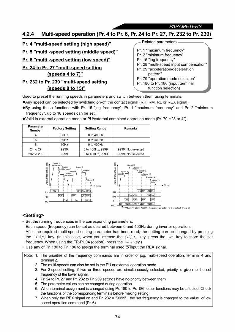
74
PARAMETERS4.2.4 Multi-speed operation (Pr. 4 to Pr. 6, Pr. 24 to Pr. 27, Pr. 232 to Pr. 239)
Pr. 4 "multi-speed setting (high speed)"Pr. 5 "multi -speed setting (middle speed)"Pr. 6 "multi -speed setting (low speed)"Pr. 24 to Pr. 27 "multi-speed setting (speeds 4 to 7)"Pr. 232 to Pr. 239 "multi-speed setting (speeds 8 to 15)"Used to preset the running speeds in parameters and switch between them using terminals.Any speed can be selected by switching on-off the contact signal (RH, RM, RL or REX signal).By using these functions with Pr. 15 "jog frequency", Pr. 1 "maximum frequency" and Pr. 2 "minimum
frequency", up to 18 speeds can be set.Valid in external operation mode or PU/external combined operation mode (Pr. 79 = "3 or 4").
<Setting>• Set the running frequencies in the corresponding parameters.
Each speed (frequency) can be set as desired between 0 and 400Hz during inverter operation.After the required multi-speed setting parameter has been read, the setting can be changed by pressingthe key. (In this case, when you release the key, press the key to store the setfrequency. When using the FR-PU04 (option), press the key.)
• Use any of Pr. 180 to Pr. 186 to assign the terminal used to input the REX signal.
Parameter Number Factory Setting Setting Range Remarks
4 60Hz 0 to 400Hz5 30Hz 0 to 400Hz6 10Hz 0 to 400Hz
24 to 27 9999 0 to 400Hz, 9999 9999: Not selected232 to 239 9999 0 to 400Hz, 9999 9999: Not selected
Note: 1. The priorities of the frequency commands are in order of jog, multi-speed operation, terminal 4 andterminal 2.
2. The multi-speeds can also be set in the PU or external operation mode.3. For 3-speed setting, if two or three speeds are simultaneously selected, priority is given to the set
frequency of the lower signal.4. Pr. 24 to Pr. 27 and Pr. 232 to Pr. 239 settings have no priority between them.5. The parameter values can be changed during operation.6. When terminal assignment is changed using Pr. 180 to Pr. 186, other functions may be affected. Check
the functions of the corresponding terminals before making setting.7. When only the REX signal on and Pr. 232 = "9999", the set frequency is changed to the value of low
speed operation command (Pr. 6).
Related parameters
Pr. 1 "maximum frequency"Pr. 2 "minimum frequency"Pr. 15 "jog frequency"Pr. 28 "multi-speed input compensation"Pr. 29 "acceleration/deceleration
pattern"Pr. 79 "operation mode selection"Pr. 180 to Pr. 186 (input terminal
function selection)
ON
ON ON ON ON
ON ON
ONONON
ONRH
RM
RL
Speed 7
Out
put f
requ
ency
(Hz) Speed 1
(high speed)Speed 2
(middle speed)
Speed 3(low speed)
Speed 4
Time
Speed 5
Speed 6
ONON ON ON ON ON ON ON
ON ON ON ON
ON ON ON ON
ON ON ON ONRH
RM
RL
REX
Speed 15
Out
put f
requ
ency
(Hz)
Time
Speed 9Speed 8
Speed 10Speed 11
Speed 12
Speed 13
Speed 14
When Pr. 232 = "9999" , frequency as set in Pr. 6 is output (Note 7)
SET
WRITE

PARAMETERS
4
4.2.5 Acceleration/deceleration time (Pr. 7, Pr. 8, Pr. 20, Pr. 21, Pr. 44, Pr. 45, Pr. 110, Pr. 111)
Pr. 7 "acceleration time"Pr. 8 "deceleration time"Pr. 20 "acceleration/deceleration reference frequency"Pr. 21 "acceleration/deceleration time increments"Pr. 44 "second acceleration/deceleration time"Pr. 45 "second deceleration time"Pr. 110 "third acceleration/deceleration time"Pr. 111 "third deceleration time"Used to set motor acceleration/deceleration time.Set a larger value for a slower speed increase/decrease or a smaller value for a faster speed increase/decrease.For acceleration time at restart after instantaneous power failure, refer to Pr. 611 "restart acceleration time." (page 94)
<Setting>• Use Pr. 21 to set the acceleration/deceleration time and minimum setting increments:
Set value "0" (factory setting)........... 0 to 3600s (minimum setting increments: 0.1s)Set value "1" .................................... 0 to 360s (minimum setting increments: 0.01s)
• When the Pr. 21 setting was changed, reset acceleration / deceleration time. (Note 5)• Use Pr. 7, Pr. 44 and Pr. 110 to set the acceleration time required to reach the frequency set in Pr. 20 from
0Hz.• Use Pr. 8, Pr. 45 and Pr. 111 to set the deceleration time required to reach 0Hz from the frequency set in
Pr. 20.• Pr. 44 and Pr. 45 are valid when the RT signal is on, and Pr. 110 and Pr. 111 are valid when the X9 signal is
on. When both RT and X9 are on, Pr. 110 and Pr. 111 are valid. (When the RT (X9) signal is on, the othersecond (third) functions such as second (third) torque boost are also selected.)
• Use any of Pr. 180 to Pr. 186 to assign the terminal used to input the X9 signal.• Set "9999" in Pr. 45 and Pr. 111 to make the deceleration time equal to the acceleration time (Pr. 44, Pr. 110).• When "9999" is set in Pr. 110, the function is made invalid.
Parameter Number Factory Setting Setting Range Remarks
77.5K or less 5 s
0 to 3600 s/0 to 360 s11K or more 15 s
87.5K or less 5 s
0 to 3600 s/0 to 360 s11K or more 15 s20 60Hz <50Hz> 1 to 400Hz21 0 0, 1 0: 0 to 3600 s, 1: 0 to 360 s
447.5K or less
5s 0 to 3600 s/0 to 360 s11K or more
457.5K or less
9999 0 to 3600 s/0 to 360 s, 9999 9999: Acceleration time = deceleration time11K or more
1107.5K or less
9999 0 to 3600 s/0 to 360 s, 9999 9999: Function invalid11K or more
1117.5K or less
9999 0 to 3600 s/0 to 360 s, 9999 9999: Acceleration time = deceleration time11K or more
Related parametersPr. 3 "base frequency"Pr. 29 "acceleration/deceleration
pattern"Pr. 180 to Pr. 186 (input terminal function selection)
Pr.20
Pr.7
Pr.44
Pr.8
Pr.45
Decelerationtime
Ou
tpu
t fr
eq
ue
ncy (
Hz)
Running frequency
Time
Accelerationtime
Pr.110 Pr.111
75

PARAMETERS
4.2.6 Electronic overcurrent protection (Pr. 9)
Pr. 9 "electronic thermal O/L relay"
Set the current of the electronic overcurrent protection to protect the motor from overheat. This featureprovides the optimum protective characteristics, including reduced motor cooling capability, at low speed.
*0.4K and 0.75K are set to 85% of the rated inverter current.
<Setting>• Set the rated current [A] of the motor.
(Normally set the rated current value at 50Hz if the motor has both 50Hz and 60Hz rated current.)• Setting of "0" makes the electronic overcurrent protection (motor protective function) invalid. (The inverter's
output transistor protective function is valid.)• When using the Mitsubishi constant torque motor, first set any of "1" or "13 to 18" in Pr.71. (This provides a
100% continuous torque characteristic in the low-speed range.) Then, set the rated motor current in Pr. 9.
Note: 1. In S-shaped acceleration/deceleration pattern A (refer to page 84), the set time is a periodrequired to reach the base frequency set in Pr. 3.• Acceleration/deceleration time calculation expression when the set frequency is the base
frequency or higher
t = × × f2 + T
T: Acceleration/deceleration time setting(s) f: Set frequency (Hz)
• Guideline for acceleration/deceleration time at the base frequency of 60Hz (0Hz to set frequency)
2. If the Pr. 20 setting is changed, the settings of calibration functions Pr. 903 and Pr. 905(frequency setting signal gains) remain unchanged. To adjust the gains, adjust calibrationfunctions Pr. 903 and Pr. 905.
3. When the setting of Pr. 7, Pr. 8, Pr. 44, Pr. 45, Pr. 110 or Pr. 111 is "0", the acceleration/deceleration time is 0.04s. At this time, set 120Hz or less in Pr. 20.
4. If the shortest acceleration/deceleration time is set, the actual motor acceleration/deceleration timecannot be made shorter than the shortest acceleration/deceleration time determined by the mechanicalsystem's J (moment of inertia) and motor torque.
5. Changing the Pr. 21 setting changes the setting values of acceleration/deceleration time (Pr. 7, Pr. 8, Pr.16, Pr. 44, Pr. 45, Pr. 110, Pr. 111, Pr. 264, Pr. 265). (The Pr. 611 setting is not changed.)<Example>When Pr. 21 = "0", setting "5.0"s in Pr. 7 and "1" in Pr. 21 changes the Pr. 7 setting to "0.5"s
Parameter Number Factory Setting Setting Range9 Rated output current* 0 to 500A
Note: 1. When two or more motors are connected to the inverter, they cannot be protected by theelectronic overcurrent protection. Install an external thermal relay to each motor.
2. When a difference between the inverter and motor capacities is large and the setting is small, theprotective characteristics of the electronic overcurrent protection will be deteriorated. In this case,use an external thermal relay.
3. A special motor cannot be protected by the electronic overcurrent protection. Use an externalthermal relay.
49
T(Pr.3)2
59
Frequency setting (Hz)Acceleration/decelerationtime (s)
60 120 200 400
5 5 12 27 10215 15 35 82 305
Related parametersPr. 71 "applied motor"
76
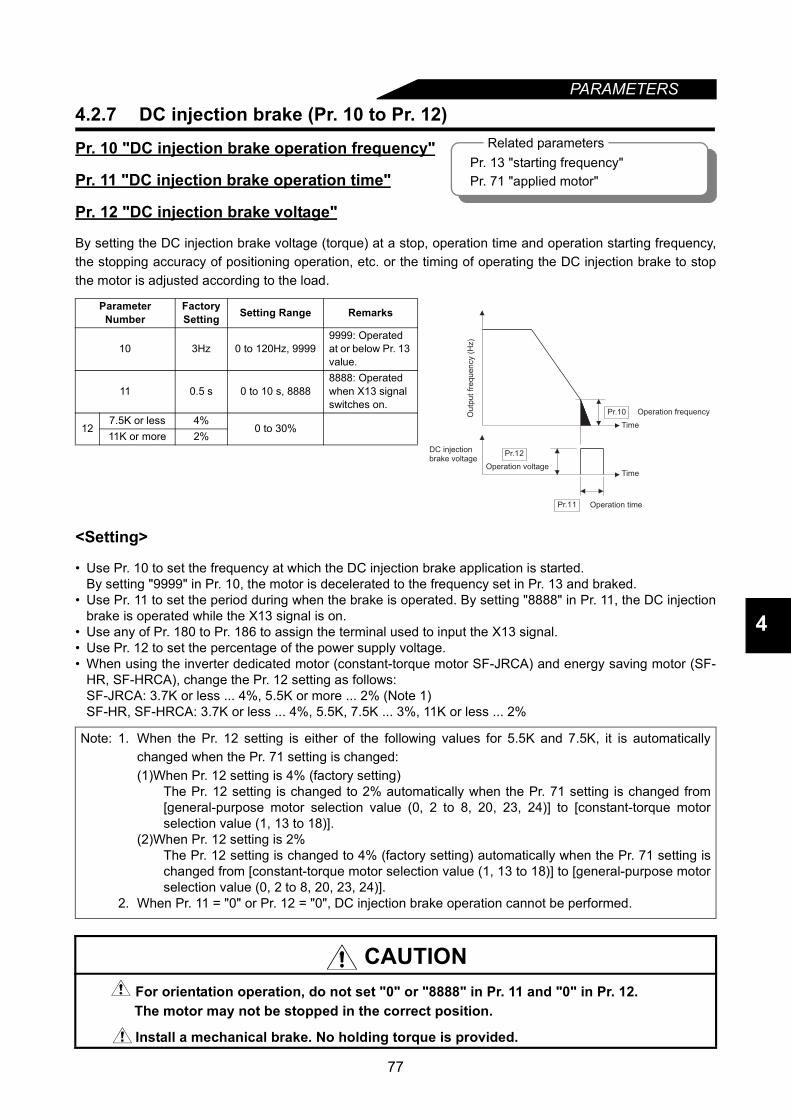
77
PARAMETERS
4
4.2.7 DC injection brake (Pr. 10 to Pr. 12)
Pr. 10 "DC injection brake operation frequency"
Pr. 11 "DC injection brake operation time"
Pr. 12 "DC injection brake voltage"
By setting the DC injection brake voltage (torque) at a stop, operation time and operation starting frequency,the stopping accuracy of positioning operation, etc. or the timing of operating the DC injection brake to stopthe motor is adjusted according to the load.
<Setting>
• Use Pr. 10 to set the frequency at which the DC injection brake application is started.By setting "9999" in Pr. 10, the motor is decelerated to the frequency set in Pr. 13 and braked.
• Use Pr. 11 to set the period during when the brake is operated. By setting "8888" in Pr. 11, the DC injectionbrake is operated while the X13 signal is on.
• Use any of Pr. 180 to Pr. 186 to assign the terminal used to input the X13 signal.• Use Pr. 12 to set the percentage of the power supply voltage.• When using the inverter dedicated motor (constant-torque motor SF-JRCA) and energy saving motor (SF-
HR, SF-HRCA), change the Pr. 12 setting as follows:SF-JRCA: 3.7K or less ... 4%, 5.5K or more ... 2% (Note 1)SF-HR, SF-HRCA: 3.7K or less ... 4%, 5.5K, 7.5K ... 3%, 11K or less ... 2%
Parameter Number
Factory Setting Setting Range Remarks
10 3Hz 0 to 120Hz, 99999999: Operated at or below Pr. 13 value.
11 0.5 s 0 to 10 s, 88888888: Operated when X13 signal switches on.
127.5K or less 4%
0 to 30%11K or more 2%
Note: 1. When the Pr. 12 setting is either of the following values for 5.5K and 7.5K, it is automaticallychanged when the Pr. 71 setting is changed:(1)When Pr. 12 setting is 4% (factory setting)
The Pr. 12 setting is changed to 2% automatically when the Pr. 71 setting is changed from[general-purpose motor selection value (0, 2 to 8, 20, 23, 24)] to [constant-torque motorselection value (1, 13 to 18)].
(2)When Pr. 12 setting is 2%The Pr. 12 setting is changed to 4% (factory setting) automatically when the Pr. 71 setting ischanged from [constant-torque motor selection value (1, 13 to 18)] to [general-purpose motorselection value (0, 2 to 8, 20, 23, 24)].
2. When Pr. 11 = "0" or Pr. 12 = "0", DC injection brake operation cannot be performed.
CAUTIONFor orientation operation, do not set "0" or "8888" in Pr. 11 and "0" in Pr. 12.The motor may not be stopped in the correct position.
Install a mechanical brake. No holding torque is provided.
Related parametersPr. 13 "starting frequency"Pr. 71 "applied motor"
Pr.10
Pr.12
Pr.11 Operation time
Ou
tpu
t fr
eq
ue
ncy (
Hz)
Operation frequency
Time
DC injectionbrake voltage
Operation voltageTime
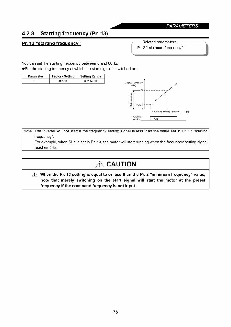
78
PARAMETERS4.2.8 Starting frequency (Pr. 13)
Pr. 13 "starting frequency"
You can set the starting frequency between 0 and 60Hz.Set the starting frequency at which the start signal is switched on.
Parameter Factory Setting Setting Range13 0.5Hz 0 to 60Hz
Note: The inverter will not start if the frequency setting signal is less than the value set in Pr. 13 "startingfrequency".For example, when 5Hz is set in Pr. 13, the motor will start running when the frequency setting signalreaches 5Hz.
CAUTION When the Pr. 13 setting is equal to or less than the Pr. 2 "minimum frequency" value,note that merely switching on the start signal will start the motor at the presetfrequency if the command frequency is not input.
60
Pr.13
ON
0
Forward rotation
Output frequency (Hz)
Setti
ng ra
nge
Frequency setting signal (V) Time
Related parametersPr. 2 "minimum frequency"
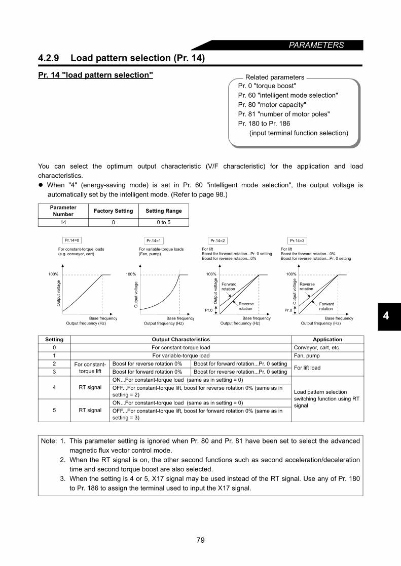
79
PARAMETERS
4
4.2.9 Load pattern selection (Pr. 14)
Pr. 14 "load pattern selection"
You can select the optimum output characteristic (V/F characteristic) for the application and loadcharacteristics. When "4" (energy-saving mode) is set in Pr. 60 "intelligent mode selection", the output voltage is
automatically set by the intelligent mode. (Refer to page 98.).
Parameter Number Factory Setting Setting Range
14 0 0 to 5
Setting Output Characteristics Application0 For constant-torque load Conveyor, cart, etc.1 For variable-torque load Fan, pump2 For constant-
torque liftBoost for reverse rotation 0% Boost for forward rotation...Pr. 0 setting
For lift load3 Boost for forward rotation 0% Boost for reverse rotation...Pr. 0 setting
4 RT signalON...For constant-torque load (same as in setting = 0)
Load pattern selection switching function using RT signal
OFF...For constant-torque lift, boost for reverse rotation 0% (same as in setting = 2)
5 RT signalON...For constant-torque load (same as in setting = 0)OFF...For constant-torque lift, boost for forward rotation 0% (same as in setting = 3)
Note: 1. This parameter setting is ignored when Pr. 80 and Pr. 81 have been set to select the advancedmagnetic flux vector control mode.
2. When the RT signal is on, the other second functions such as second acceleration/decelerationtime and second torque boost are also selected.
3. When the setting is 4 or 5, X17 signal may be used instead of the RT signal. Use any of Pr. 180to Pr. 186 to assign the terminal used to input the X17 signal.
Pr. 0 "torque boost"Pr. 60 "intelligent mode selection"Pr. 80 "motor capacity"Pr. 81 "number of motor poles"Pr. 180 to Pr. 186 (input terminal function selection)
Related parameters
100%
Pr.14=0
Output frequency (Hz)
For constant-torque loads(e.g. conveyor, cart)
Out
put v
olta
ge
Base frequencyOutput frequency (Hz)
For variable-torque loads(Fan, pump)
100%
Out
put v
olta
ge
Base frequency
Pr.14=1
Output frequency (Hz)
For liftBoost for forward rotation...Pr. 0 settingBoost for reverse rotation...0%
100%
Pr.0
Out
put v
olta
ge
Forwardrotation
Reverserotation
Base frequency
Pr.14=2
100%
Pr.0
Pr.14=3
Output frequency (Hz)
For liftBoost for forward rotation...0%Boost for reverse rotation...Pr. 0 setting
Out
put v
olta
ge Reverserotation
Forwardrotation
Base frequency
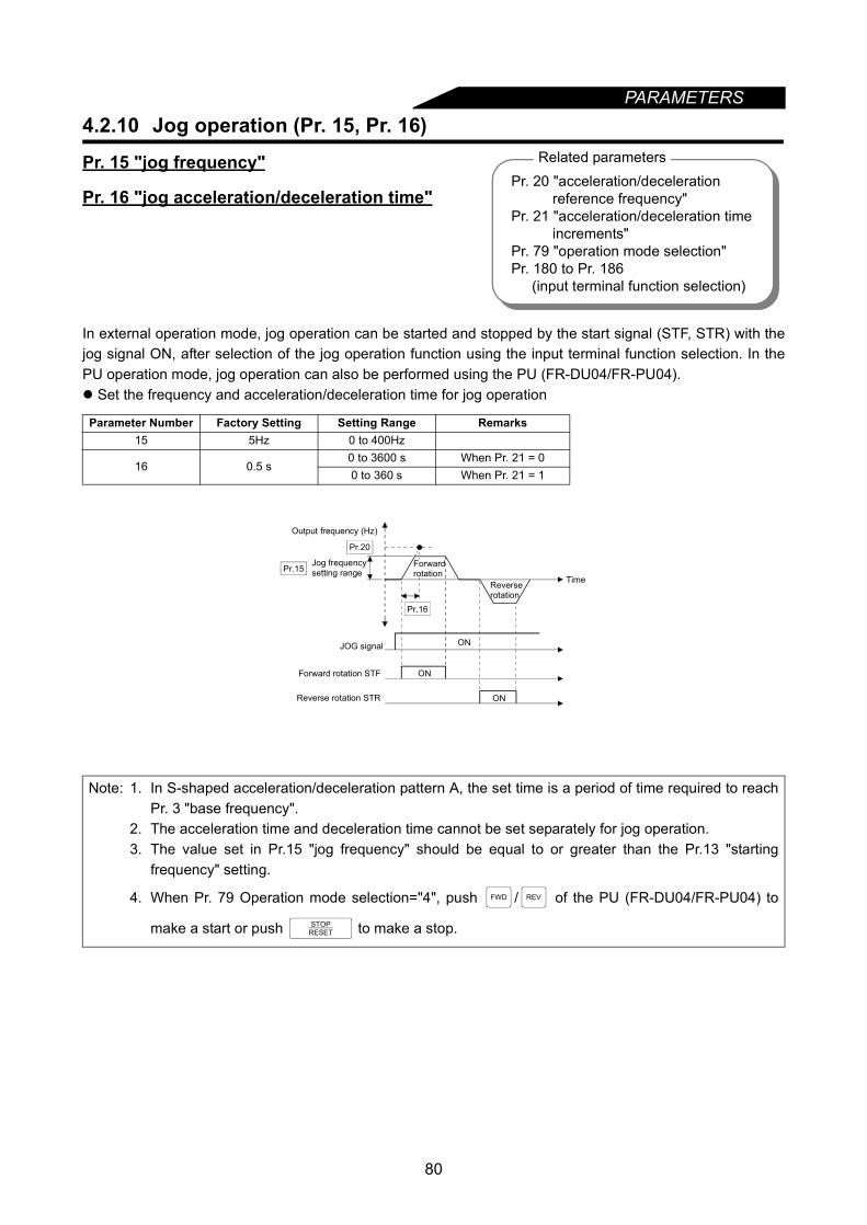
PARAMETERS
4.2.10 Jog operation (Pr. 15, Pr. 16)Pr. 15 "jog frequency"
Pr. 16 "jog acceleration/deceleration time"
In external operation mode, jog operation can be started and stopped by the start signal (STF, STR) with thejog signal ON, after selection of the jog operation function using the input terminal function selection. In thePU operation mode, jog operation can also be performed using the PU (FR-DU04/FR-PU04). Set the frequency and acceleration/deceleration time for jog operation
Parameter Number Factory Setting Setting Range Remarks15 5Hz 0 to 400Hz
16 0.5 s0 to 3600 s When Pr. 21 = 00 to 360 s When Pr. 21 = 1
Note: 1. In S-shaped acceleration/deceleration pattern A, the set time is a period of time required to reachPr. 3 "base frequency".
2. The acceleration time and deceleration time cannot be set separately for jog operation.3. The value set in Pr.15 "jog frequency" should be equal to or greater than the Pr.13 "starting
frequency" setting.
4. When Pr. 79 Operation mode selection="4", push / of the PU (FR-DU04/FR-PU04) to
make a start or push to make a stop.
Related parametersPr. 20 "acceleration/deceleration
reference frequency"Pr. 21 "acceleration/deceleration time
increments"Pr. 79 "operation mode selection"Pr. 180 to Pr. 186
(input terminal function selection)
Pr.20
Pr.15
Pr.16
ON
ON
ONReverse rotation STR
Output frequency (Hz)
Jog frequencysetting range
Reverserotation
Time
Forwardrotation
Forward rotation STF
JOG signal
FWD REV
STOPRESET
80
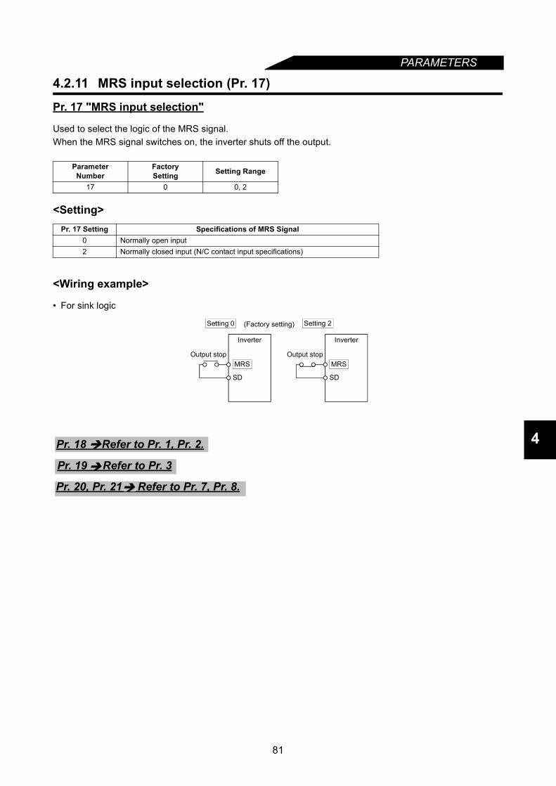
PARAMETERS
4
4.2.11 MRS input selection (Pr. 17)
Pr. 17 "MRS input selection"
Used to select the logic of the MRS signal.When the MRS signal switches on, the inverter shuts off the output.
<Setting>
<Wiring example>
• For sink logic
ParameterNumber
FactorySetting Setting Range
17 0 0, 2
Pr. 17 Setting Specifications of MRS Signal0 Normally open input2 Normally closed input (N/C contact input specifications)
MRS
SD
MRS
SD
Setting 0 (Factory setting) Setting 2
Output stop Output stop
Inverter Inverter
Pr. 18 Refer to Pr. 1, Pr. 2.
Pr. 19 Refer to Pr. 3
Pr. 20, Pr. 21 Refer to Pr. 7, Pr. 8.
81

PARAMETERS
4.2.12 Stall prevention (Pr. 22, Pr. 23, Pr. 66, Pr. 148, Pr. 149, Pr. 154)Pr. 22 "stall prevention operation level"Pr. 23 "stall prevention operation level compensation factor at double speed"Pr. 66 "stall prevention operation level reduction starting frequency"Pr. 148 "stall prevention operation level at 0V input"Pr. 149 "stall prevention operation level at 10V
input"Pr. 154 "voltage reduction selection during stall
prevention operation" Set the output current level (% to the inverter rated current) at which the output frequency is adjusted so
that the inverter will not come to an alarm stop due to overcurrent etc. For high-speed operation at or over the more base frequency, acceleration may not be made because the
motor current does not increase. To improve the operation characteristics of the motor in such a case, thestall prevention level in the high-frequency range can be reduced. This is effective for operation of acentrifugal separator up to the high-speed range. Normally, set 60Hz <50Hz> in Pr. 66 and 100% in Pr. 23.
For operation in the high-frequency range, the current in the locked motor state is smaller than the ratedoutput current of the inverter and the inverter does not result in an alarm (protective function is not activated)if the motor is at a stop. To improve this and activate the alarm, the stall prevention level can be reduced.
In order to provide torque during stall prevention, Pr. 154 is factory-set not to reduce the output voltage.The setting of reducing the output voltage further decreases the probability of overcurrent trip occurrence.
The stall prevention operation level can be varied by entering the analog signal into terminal 1.Parameter
NumberFactorySetting Setting Range Remarks
22 150% 0 to 200%, 9999 9999: Analog variable23 9999 0 to 200%, 9999 9999: Constant according to Pr. 2266 60Hz<50Hz> 0 to 400Hz148 150% 0 to 200% (Bias)149 200% 0 to 200% (Gain)
154 1 0, 1 0: Output voltage reduced1: Output voltage not reduced
Related parametersPr. 48 "second stall prevention operation current"Pr. 49 "second stall prevention operation frequency"Pr. 73 "0-5V/0-10V selection"Pr. 114 "third stall prevention operation current"Pr. 115 "third stall prevention operation frequency"Pr. 156 "stall prevention operation selection"
Pr.22
Pr.23
Pr.66 400Hz Output frequency (Hz)
Stal
l pre
vent
ion
oper
atio
n le
vel (
%)
Pr. 23 = 9999
Reduction ratiocompensation factor (%)
150
90
604530
22.5
600 100 200 300 400Output frequency (Hz)
Setting example (Pr.22=150%, Pr.23=100%, Pr.66=60Hz)
Stal
l pre
vent
ion
oper
atio
n le
vel (
%)
( )
( )
0%
0V
Pr.148
Pr.149
10(5)V
Input voltage (V)(across frequency setting terminals 1-5)S
tall
pre
ve
ntio
n o
pe
ratio
n le
ve
l (%
)
130%
170%
82

PARAMETERS
4
<Setting>
• In Pr. 22, set the stall prevention operation level. Normally set it to 150% (factory setting). Set "0" in Pr. 22to disable the stall prevention operation.
• To reduce the stall prevention operation level in the high-frequency range, set the reduction startingfrequency in Pr. 66 and the reduction ratio compensation factor in Pr. 23.
Formula for stall prevention operation level
• By setting "9999" (factory setting) in Pr. 23, the stall prevention operation level is constant at the Pr. 22setting up to 400Hz.
• Set "9999" in Pr. 22 to vary the stall prevention operation level using the analog signal (0-5V/0-10V)entered to the frequency setting auxiliary input terminal [1]. (Use Pr. 73 to select between 10V and 5V.)
• Use Pr. 148 and Pr. 149 to adjust the gain and bias of the analog signal.• Set "0" in Pr. 154 to reduce the output voltage during stall prevention operation.
4.2.13 Multi-speed input compensation (Pr. 28)
Pr. 28 "multi-speed input compensation"
By entering a compensation signal into the frequency setting auxiliary input terminal 1 (Note 2), the speeds(frequencies) of multi-speed settings or the speed setting made by remote setting function can becompensated for.
Stall prevention operation level (%) = A + B × [ Pr.22-A ] ×[Pr.23-100 ]Pr.22-B 100
where, A = Pr.66 (Hz) × Pr.22 (%) ,B= Pr.66 (Hz) × Pr.22(%)output frequency (Hz) 400Hz
Note: 1. When Pr. 22 = "9999", terminal 1 is exclusively used for setting the stall prevention operationlevel. The auxiliary input and override functions are not activated.
2. When high-response current limit is set in Pr. 156 (factory setting), do not set the Pr. 22 value to170% or higher. If such setting is made, torque will not be developed.
CAUTIONDo not set a too small value as the stall prevention operation current. Otherwise, torque generated will reduce.Test operation must be performed. Stall prevention operation during acceleration mayincrease the acceleration time.Stall prevention operation during constant speed may change the speed suddenly.Stall prevention operation during deceleration may increase the deceleration time, increasing the deceleration distance.
Parameter Number
FactorySetting Setting Range Remarks
28 0 0, 1 0: Not compensated,1: Compensated
Note: 1. Use Pr. 73 to select the compensation input voltage between 0 to ±5V and 0 to ±10V.2. When any of "4, 5, 14 and 15" is set in Pr. 73, the compensation signal is entered into terminal 2.
(Override functions)
Pr. 24 to Pr. 27 Refer to Pr. 4 to Pr. 6.
Pr. 4 to Pr. 6, Pr. 24 to Pr.27, Pr. 232 toPr. 239 (multi-speed operation) Pr. 59 "remote setting function selection"Pr. 73 "0-5V/0-10V selection"
Related parameters
83
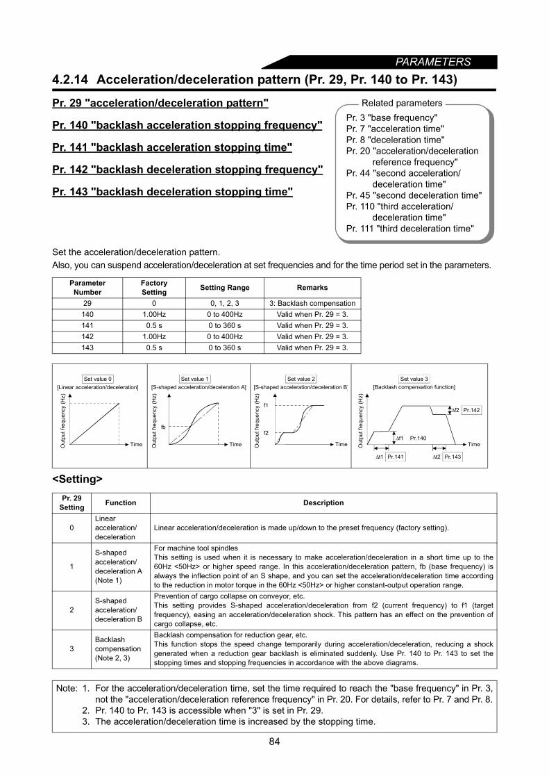
84
PARAMETERS4.2.14 Acceleration/deceleration pattern (Pr. 29, Pr. 140 to Pr. 143)
Pr. 29 "acceleration/deceleration pattern"
Pr. 140 "backlash acceleration stopping frequency"
Pr. 141 "backlash acceleration stopping time"
Pr. 142 "backlash deceleration stopping frequency"
Pr. 143 "backlash deceleration stopping time"
Set the acceleration/deceleration pattern.Also, you can suspend acceleration/deceleration at set frequencies and for the time period set in the parameters.
<Setting>
Parameter Number
FactorySetting Setting Range Remarks
29 0 0, 1, 2, 3 3: Backlash compensation140 1.00Hz 0 to 400Hz Valid when Pr. 29 = 3.141 0.5 s 0 to 360 s Valid when Pr. 29 = 3.142 1.00Hz 0 to 400Hz Valid when Pr. 29 = 3.143 0.5 s 0 to 360 s Valid when Pr. 29 = 3.
Pr. 29 Setting Function Description
0Linear acceleration/deceleration
Linear acceleration/deceleration is made up/down to the preset frequency (factory setting).
1
S-shaped acceleration/deceleration A (Note 1)
For machine tool spindlesThis setting is used when it is necessary to make acceleration/deceleration in a short time up to the60Hz <50Hz> or higher speed range. In this acceleration/deceleration pattern, fb (base frequency) isalways the inflection point of an S shape, and you can set the acceleration/deceleration time accordingto the reduction in motor torque in the 60Hz <50Hz> or higher constant-output operation range.
2S-shaped acceleration/deceleration B
Prevention of cargo collapse on conveyor, etc.This setting provides S-shaped acceleration/deceleration from f2 (current frequency) to f1 (targetfrequency), easing an acceleration/deceleration shock. This pattern has an effect on the prevention ofcargo collapse, etc.
3Backlash compensation (Note 2, 3)
Backlash compensation for reduction gear, etc.This function stops the speed change temporarily during acceleration/deceleration, reducing a shockgenerated when a reduction gear backlash is eliminated suddenly. Use Pr. 140 to Pr. 143 to set thestopping times and stopping frequencies in accordance with the above diagrams.
Note: 1. For the acceleration/deceleration time, set the time required to reach the "base frequency" in Pr. 3,not the "acceleration/deceleration reference frequency" in Pr. 20. For details, refer to Pr. 7 and Pr. 8.
2. Pr. 140 to Pr. 143 is accessible when "3" is set in Pr. 29.3. The acceleration/deceleration time is increased by the stopping time.
Related parametersPr. 3 "base frequency"Pr. 7 "acceleration time"Pr. 8 "deceleration time"Pr. 20 "acceleration/deceleration
reference frequency"Pr. 44 "second acceleration/
deceleration time"Pr. 45 "second deceleration time"Pr. 110 "third acceleration/
deceleration time"Pr. 111 "third deceleration time"
Time
[Linear acceleration/deceleration]
Out
put f
requ
ency
(Hz)
Set value 0
fb
[S-shaped acceleration/deceleration A]
TimeOut
put f
requ
ency
(Hz)
Set value 1
f1
f2
[S-shaped acceleration/deceleration B]
Out
put f
requ
ency
(Hz)
Time
Set value 2
Pr.142
Pr.143Pr.141
Out
put f
requ
ency
(Hz)
Set value 3[Backlash compensation function]
Time
t2t1
Pr.140f1
f2
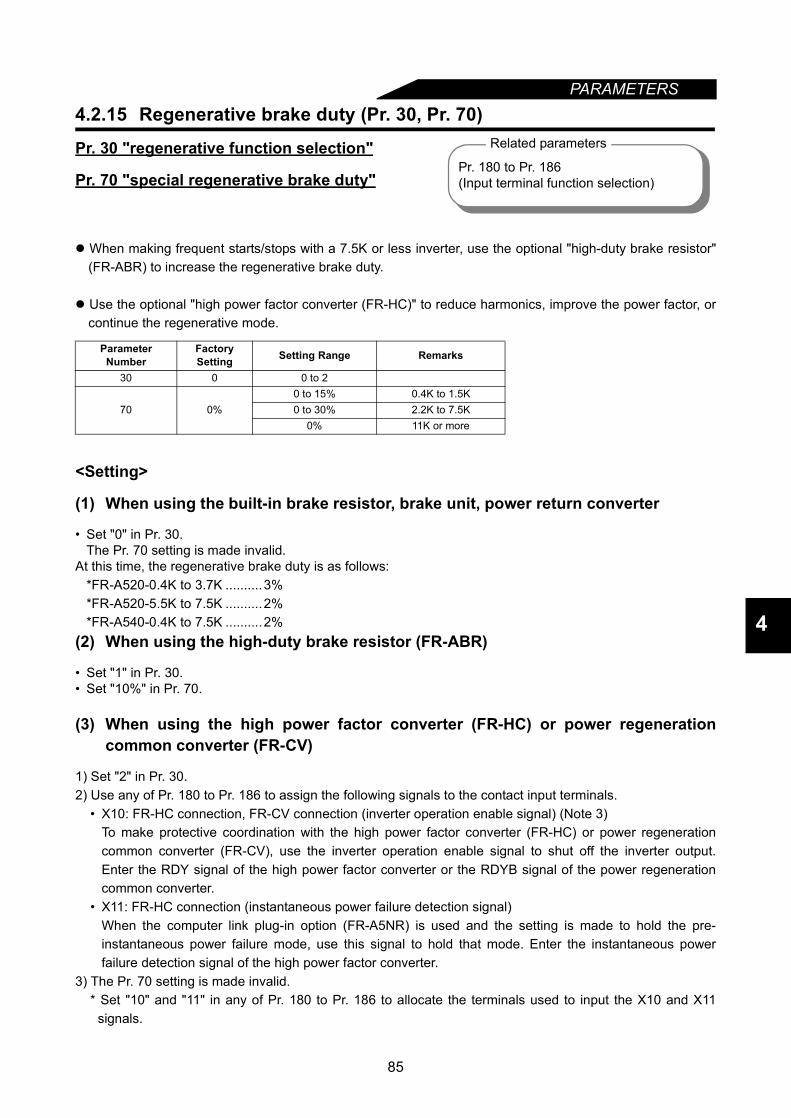
PARAMETERS
4
4.2.15 Regenerative brake duty (Pr. 30, Pr. 70)
Pr. 30 "regenerative function selection"
Pr. 70 "special regenerative brake duty"
When making frequent starts/stops with a 7.5K or less inverter, use the optional "high-duty brake resistor"(FR-ABR) to increase the regenerative brake duty.
Use the optional "high power factor converter (FR-HC)" to reduce harmonics, improve the power factor, orcontinue the regenerative mode.
<Setting>
(1) When using the built-in brake resistor, brake unit, power return converter
• Set "0" in Pr. 30.The Pr. 70 setting is made invalid.
At this time, the regenerative brake duty is as follows:*FR-A520-0.4K to 3.7K ..........3%*FR-A520-5.5K to 7.5K ..........2%*FR-A540-0.4K to 7.5K ..........2%
(2) When using the high-duty brake resistor (FR-ABR)
• Set "1" in Pr. 30.• Set "10%" in Pr. 70.
(3) When using the high power factor converter (FR-HC) or power regenerationcommon converter (FR-CV)
1) Set "2" in Pr. 30.2) Use any of Pr. 180 to Pr. 186 to assign the following signals to the contact input terminals.
• X10: FR-HC connection, FR-CV connection (inverter operation enable signal) (Note 3)To make protective coordination with the high power factor converter (FR-HC) or power regenerationcommon converter (FR-CV), use the inverter operation enable signal to shut off the inverter output.Enter the RDY signal of the high power factor converter or the RDYB signal of the power regenerationcommon converter.
• X11: FR-HC connection (instantaneous power failure detection signal)When the computer link plug-in option (FR-A5NR) is used and the setting is made to hold the pre-instantaneous power failure mode, use this signal to hold that mode. Enter the instantaneous powerfailure detection signal of the high power factor converter.
3) The Pr. 70 setting is made invalid.* Set "10" and "11" in any of Pr. 180 to Pr. 186 to allocate the terminals used to input the X10 and X11
signals.
Parameter Number
Factory Setting Setting Range Remarks
30 0 0 to 2
70 0%0 to 15% 0.4K to 1.5K0 to 30% 2.2K to 7.5K
0% 11K or more
Related parameters
Pr. 180 to Pr. 186(Input terminal function selection)
85
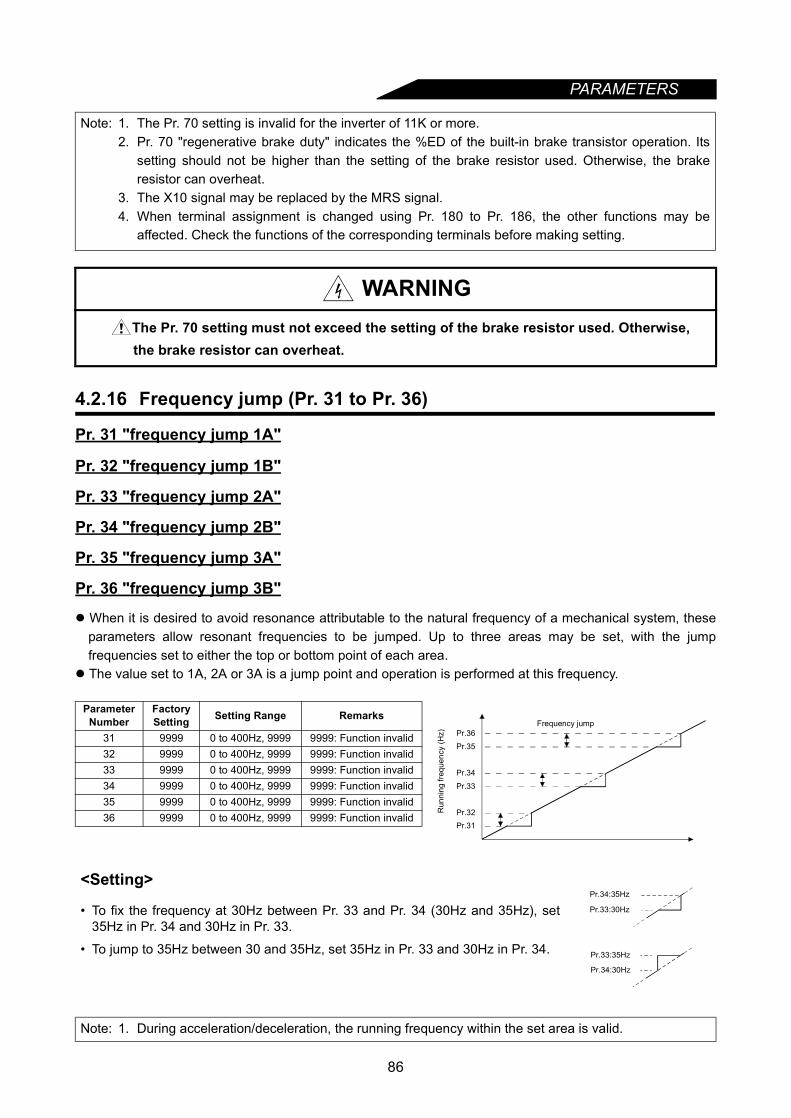
PARAMETERS
4.2.16 Frequency jump (Pr. 31 to Pr. 36)
Pr. 31 "frequency jump 1A"
Pr. 32 "frequency jump 1B"
Pr. 33 "frequency jump 2A"
Pr. 34 "frequency jump 2B"
Pr. 35 "frequency jump 3A"
Pr. 36 "frequency jump 3B"
When it is desired to avoid resonance attributable to the natural frequency of a mechanical system, theseparameters allow resonant frequencies to be jumped. Up to three areas may be set, with the jumpfrequencies set to either the top or bottom point of each area.
The value set to 1A, 2A or 3A is a jump point and operation is performed at this frequency.
Note: 1. The Pr. 70 setting is invalid for the inverter of 11K or more.2. Pr. 70 "regenerative brake duty" indicates the %ED of the built-in brake transistor operation. Its
setting should not be higher than the setting of the brake resistor used. Otherwise, the brakeresistor can overheat.
3. The X10 signal may be replaced by the MRS signal.4. When terminal assignment is changed using Pr. 180 to Pr. 186, the other functions may be
affected. Check the functions of the corresponding terminals before making setting.
WARNINGThe Pr. 70 setting must not exceed the setting of the brake resistor used. Otherwise, the brake resistor can overheat.
Parameter Number
Factory Setting Setting Range Remarks
31 9999 0 to 400Hz, 9999 9999: Function invalid32 9999 0 to 400Hz, 9999 9999: Function invalid33 9999 0 to 400Hz, 9999 9999: Function invalid34 9999 0 to 400Hz, 9999 9999: Function invalid35 9999 0 to 400Hz, 9999 9999: Function invalid36 9999 0 to 400Hz, 9999 9999: Function invalid
<Setting>
• To fix the frequency at 30Hz between Pr. 33 and Pr. 34 (30Hz and 35Hz), set35Hz in Pr. 34 and 30Hz in Pr. 33.
• To jump to 35Hz between 30 and 35Hz, set 35Hz in Pr. 33 and 30Hz in Pr. 34.
Note: 1. During acceleration/deceleration, the running frequency within the set area is valid.
Pr.31Pr.32
Pr.33
Pr.34
Pr.35
Pr.36Frequency jump
Run
ning
freq
uenc
y (H
z)
Pr.34:35Hz
Pr.33:30Hz
Pr.33:35Hz
Pr.34:30Hz
86
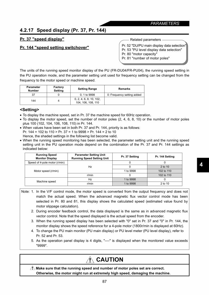
87
PARAMETERS
4
4.2.17 Speed display (Pr. 37, Pr. 144)
Pr. 37 "speed display"
Pr. 144 "speed setting switchover"
The units of the running speed monitor display of the PU (FR-DU04/FR-PU04), the running speed setting inthe PU operation mode, and the parameter setting unit used for frequency setting can be changed from thefrequency to the motor speed or machine speed.
<Setting>• To display the machine speed, set in Pr. 37 the machine speed for 60Hz operation.• To display the motor speed, set the number of motor poles (2, 4, 6, 8, 10) or the number of motor poles
plus 100 (102, 104, 106, 108, 110) in Pr. 144.• When values have been set in both Pr. 37 and Pr. 144, priority is as follows:
Pr. 144 = 102 to 110 > Pr. 37 = 1 to 9998 > Pr. 144 = 2 to 10Hence, the shaded settings in the following list become valid.
• When the running speed monitoring has been selected, the parameter setting unit and the running speedsetting unit in the PU operation mode depend on the combination of the Pr. 37 and Pr. 144 settings asindicated below:
Parameter Number
FactorySetting Setting Range Remarks
37 0 0, 1 to 9998 0: Frequency setting added
144 4 0, 2, 4, 6, 8, 10, 102,104, 106, 108, 110
Running SpeedMonitor Display
Parameter Setting UnitRunning Speed Setting Unit Pr. 37 Setting Pr. 144 Setting
Speed of 4-pole motor (r/min)Hz
0 0
Motor speed (r/min)0 2 to 10
1 to 9998 102 to 110r/min 0 102 to 110
Machine speedHz 1 to 9998 0
r/min 1 to 9998 2 to 10
Note: 1. In the V/F control mode, the motor speed is converted from the output frequency and does notmatch the actual speed. When the advanced magnetic flux vector control mode has beenselected in Pr. 80 and 81, this display shows the calculated speed (estimated value found bymotor slippage calculation).
2. During encoder feedback control, the data displayed is the same as in advanced magnetic fluxvector control. Note that the speed displayed is the actual speed from the encoder.
3. When the running speed display has been selected with "0" set in Pr. 37 and "0" in Pr. 144, themonitor display shows the speed reference for a 4-pole motor (1800r/min is displayed at 60Hz).
4. To change the PU main monitor (PU main display) or PU level meter (PU level display), refer toPr. 52 and Pr. 53.
5. As the operation panel display is 4 digits, "----" is displayed when the monitored value exceeds"9999".
CAUTIONMake sure that the running speed and number of motor poles set are correct.Otherwise, the motor might run at extremely high speed, damaging the machine.
Related parameters
Pr. 52 "DU/PU main display data selection"Pr. 53 "PU level display data selection"Pr. 80 "motor capacity"Pr. 81 "number of motor poles"
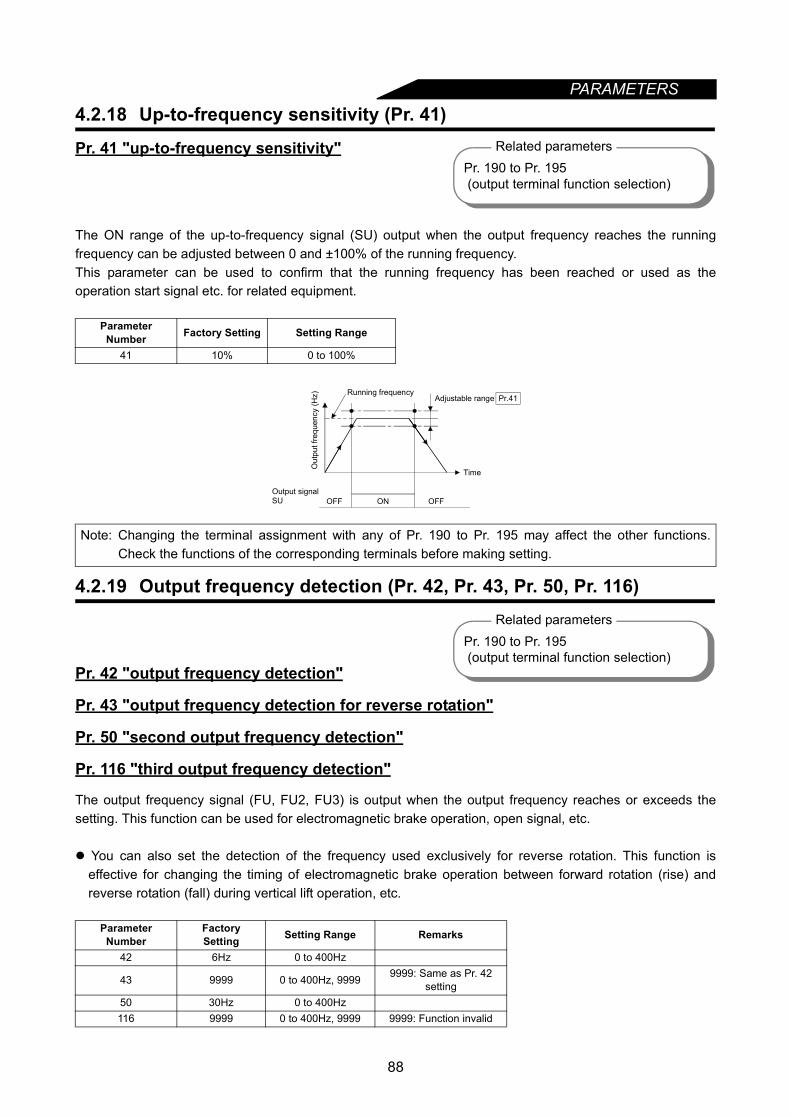
PARAMETERS
4.2.18 Up-to-frequency sensitivity (Pr. 41)Pr. 41 "up-to-frequency sensitivity"
The ON range of the up-to-frequency signal (SU) output when the output frequency reaches the runningfrequency can be adjusted between 0 and ±100% of the running frequency.This parameter can be used to confirm that the running frequency has been reached or used as theoperation start signal etc. for related equipment.
4.2.19 Output frequency detection (Pr. 42, Pr. 43, Pr. 50, Pr. 116)
Pr. 42 "output frequency detection"
Pr. 43 "output frequency detection for reverse rotation"
Pr. 50 "second output frequency detection"
Pr. 116 "third output frequency detection"
The output frequency signal (FU, FU2, FU3) is output when the output frequency reaches or exceeds thesetting. This function can be used for electromagnetic brake operation, open signal, etc.
You can also set the detection of the frequency used exclusively for reverse rotation. This function iseffective for changing the timing of electromagnetic brake operation between forward rotation (rise) andreverse rotation (fall) during vertical lift operation, etc.
Parameter Number Factory Setting Setting Range
41 10% 0 to 100%
Note: Changing the terminal assignment with any of Pr. 190 to Pr. 195 may affect the other functions.Check the functions of the corresponding terminals before making setting.
ParameterNumber
FactorySetting Setting Range Remarks
42 6Hz 0 to 400Hz
43 9999 0 to 400Hz, 9999 9999: Same as Pr. 42 setting
50 30Hz 0 to 400Hz116 9999 0 to 400Hz, 9999 9999: Function invalid
Related parametersPr. 190 to Pr. 195 (output terminal function selection)
ON
Pr.41
Output signalSU
Out
put f
requ
ency
(Hz) Running frequency
Adjustable range
Time
OFF OFF
Related parametersPr. 190 to Pr. 195 (output terminal function selection)
88
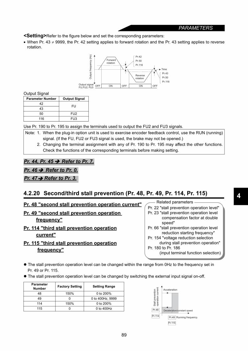
PARAMETERS
4
<Setting>Refer to the figure below and set the corresponding parameters:• When Pr. 43 ≠ 9999, the Pr. 42 setting applies to forward rotation and the Pr. 43 setting applies to reverse
rotation.
Output Signal
Use Pr. 190 to Pr. 195 to assign the terminals used to output the FU2 and FU3 signals.
4.2.20 Second/third stall prevention (Pr. 48, Pr. 49, Pr. 114, Pr. 115)
Pr. 48 "second stall prevention operation current"Pr. 49 "second stall prevention operation frequency"Pr. 114 "third stall prevention operation current"Pr. 115 "third stall prevention operation frequency"
The stall prevention operation level can be changed within the range from 0Hz to the frequency set in Pr. 49 or Pr. 115.
The stall prevention operation level can be changed by switching the external input signal on-off.
Parameter Number Output Signal42
FU4350 FU2116 FU3
Note: 1. When the plug-in option unit is used to exercise encoder feedback control, use the RUN (running)signal. (If the FU, FU2 or FU3 signal is used, the brake may not be opened.)
2. Changing the terminal assignment with any of Pr. 190 to Pr. 195 may affect the other functions.Check the functions of the corresponding terminals before making setting.
Parameter Number Factory Setting Setting Range
48 150% 0 to 200%49 0 0 to 400Hz, 9999114 150% 0 to 200%115 0 0 to 400Hz
Output signalFU,FU2
Ou
tpu
t fr
eq
ue
ncy (
Hz)
Forwardrotation
Reverserotation
Time
OFF OFF OFFON ON
Pr.50
Pr.42
Pr.116
Pr.50
Pr.43
Pr.116
, FU3
Pr. 44, Pr. 45 Refer to Pr. 7.
Pr. 46 Refer to Pr. 0.Pr. 47 Refer to Pr. 3.
Related parametersPr. 22 "stall prevention operation level"Pr. 23 "stall prevention operation level
compensation factor at double speed"
Pr. 66 "stall prevention operation level reduction starting frequency"
Pr. 154 "voltage reduction selection during stall prevention operation"
Pr. 180 to Pr. 186 (input terminal function selection)
Running frequency
Sta
ll p
reve
ntio
no
pe
ratio
n c
urr
en
t
Acceleration
Deceleration/constant speed
Pr.49
Pr.48
Pr.115
Pr.114
89
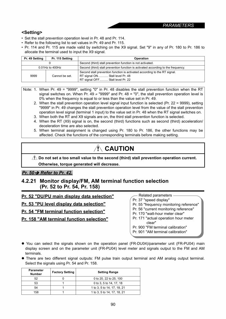
PARAMETERS
<Setting>• Set the stall prevention operation level in Pr. 48 and Pr. 114.• Refer to the following list to set values in Pr. 49 and Pr. 115.• Pr. 114 and Pr. 115 are made valid by switching on the X9 signal. Set "9" in any of Pr. 180 to Pr. 186 toallocate the terminal used to input the X9 signal.
4.2.21 Monitor display/FM, AM terminal function selection (Pr. 52 to Pr. 54, Pr. 158)
Pr. 52 "DU/PU main display data selection"Pr. 53 "PU level display data selection"Pr. 54 "FM terminal function selection"Pr. 158 "AM terminal function selection"
You can select the signals shown on the operation panel (FR-DU04)/parameter unit (FR-PU04) maindisplay screen and on the parameter unit (FR-PU04) level meter and signals output to the FM and AMterminals.
There are two different signal outputs: FM pulse train output terminal and AM analog output terminal.Select the signals using Pr. 54 and Pr. 158.
Pr. 49 Setting Pr. 115 Setting Operation0 Second (third) stall prevention function is not activated.
0.01Hz to 400Hz Second (third) stall prevention function is activated according to the frequency.
9999 Cannot be set.Second stall prevention function is activated according to the RT signal.RT signal ON............ Stall level Pr. 48RT signal OFF.......... Stall level Pr. 22
Note: 1. When Pr. 49 = "9999", setting "0" in Pr. 48 disables the stall prevention function when the RTsignal switches on. When Pr. 49 ≠ "9999" and Pr. 48 = "0", the stall prevention operation level is0% when the frequency is equal to or less than the value set in Pr. 49.
2. When the stall prevention operation level signal input function is selected (Pr. 22 = 9999), setting"9999" in Pr. 49 changes the stall prevention operation level from the value of the stall preventionoperation level signal (terminal 1 input) to the value set in Pr. 48 when the RT signal switches on.
3. When both the RT and X9 signals are on, the third stall prevention function is selected.4. When the RT (X9) signal is on, the second (third) functions such as second (third) acceleration/
deceleration time are also selected.5. When terminal assignment is changed using Pr. 180 to Pr. 186, the other functions may be
affected. Check the functions of the corresponding terminals before making setting.
CAUTIONDo not set a too small value to the second (third) stall prevention operation current. Otherwise, torque generated will decrease.
Parameter Number Factory Setting Setting Range
52 0 0 to 20, 22 to 25, 10053 1 0 to 3, 5 to 14, 17, 1854 1 1 to 3, 5 to 14, 17, 18, 21158 1 1 to 3, 5 to 14, 17, 18, 21
Pr. 50 Refer to Pr. 42.
Pr. 37 "speed display"Pr. 55 "frequency monitoring reference"Pr. 56 "current monitoring reference"Pr. 170 "watt-hour meter clear"Pr. 171 "actual operation hour meter
clear"Pr. 900 "FM terminal calibration"Pr. 901 "AM terminal calibration"
Related parameters
90
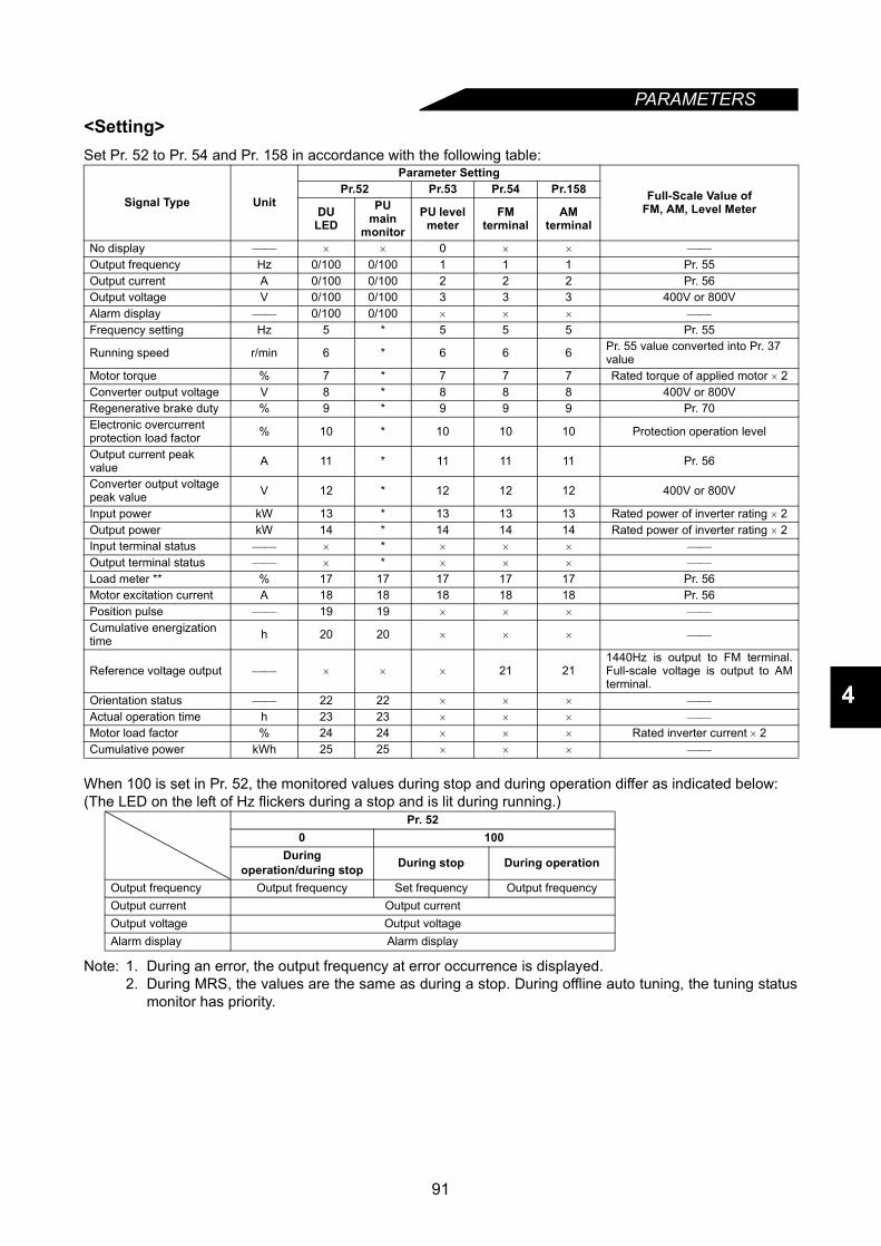
PARAMETERS
4
<Setting>Set Pr. 52 to Pr. 54 and Pr. 158 in accordance with the following table:
When 100 is set in Pr. 52, the monitored values during stop and during operation differ as indicated below:(The LED on the left of Hz flickers during a stop and is lit during running.)
Note: 1. During an error, the output frequency at error occurrence is displayed.2. During MRS, the values are the same as during a stop. During offline auto tuning, the tuning status
monitor has priority.
Signal Type Unit
Parameter Setting
Full-Scale Value ofFM, AM, Level Meter
Pr.52 Pr.53 Pr.54 Pr.158
DULED
PU main
monitorPU level
meterFM
terminalAM
terminal
No display × × 0 × ×
Output frequency Hz 0/100 0/100 1 1 1 Pr. 55Output current A 0/100 0/100 2 2 2 Pr. 56Output voltage V 0/100 0/100 3 3 3 400V or 800VAlarm display 0/100 0/100 × × ×
Frequency setting Hz 5 * 5 5 5 Pr. 55
Running speed r/min 6 * 6 6 6 Pr. 55 value converted into Pr. 37 value
Motor torque % 7 * 7 7 7 Rated torque of applied motor × 2Converter output voltage V 8 * 8 8 8 400V or 800VRegenerative brake duty % 9 * 9 9 9 Pr. 70Electronic overcurrent protection load factor % 10 * 10 10 10 Protection operation level
Output current peak value A 11 * 11 11 11 Pr. 56
Converter output voltage peak value V 12 * 12 12 12 400V or 800V
Input power kW 13 * 13 13 13 Rated power of inverter rating × 2Output power kW 14 * 14 14 14 Rated power of inverter rating × 2Input terminal status × * × × ×
Output terminal status × * × × ×
Load meter ** % 17 17 17 17 17 Pr. 56Motor excitation current A 18 18 18 18 18 Pr. 56Position pulse 19 19 × × ×
Cumulative energization time h 20 20 × × ×
Reference voltage output × × × 21 211440Hz is output to FM terminal.Full-scale voltage is output to AMterminal.
Orientation status 22 22 × × ×
Actual operation time h 23 23 × × ×
Motor load factor % 24 24 × × × Rated inverter current × 2Cumulative power kWh 25 25 × × ×
Pr. 520 100
Duringoperation/during stop During stop During operation
Output frequency Output frequency Set frequency Output frequencyOutput current Output currentOutput voltage Output voltageAlarm display Alarm display
91
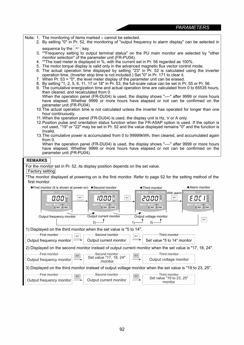
PARAMETERS
Note: 1. The monitoring of items marked × cannot be selected.2. By setting "0" in Pr. 52, the monitoring of "output frequency to alarm display" can be selected in
sequence by the key.3. *"Frequency setting to output terminal status" on the PU main monitor are selected by "other
monitor selection" of the parameter unit (FR-PU04).4. **The load meter is displayed in %, with the current set in Pr. 56 regarded as 100%.5. The motor torque display is valid only in the advanced magnetic flux vector control mode.6. The actual operation time displayed by setting "23" in Pr. 52 is calculated using the inverter
operation time. (Inverter stop time is not included.) Set "0" in Pr. 171 to clear it.7. When Pr. 53 = "0", the level meter display of the parameter unit can be erased.8. By setting "1, 2, 5, 6, 11, 17 or 18" in Pr. 53, the full-scale value can be set in Pr. 55 or Pr. 56.9. The cumulative energization time and actual operation time are calculated from 0 to 65535 hours,
then cleared, and recalculated from 0.When the operation panel (FR-DU04) is used, the display shows "----" after 9999 or more hourshave elapsed. Whether 9999 or more hours have elapsed or not can be confirmed on theparameter unit (FR-PU04).
10.The actual operation time is not calculated unless the inverter has operated for longer than onehour continuously.
11.When the operation panel (FR-DU04) is used, the display unit is Hz, V or A only.12.Position pulse and orientation status function when the FR-A5AP option is used. If the option is
not used, "19" or "22" may be set in Pr. 52 and the value displayed remains "0" and the function isinvalid.
13.The cumulative power is accumulated from 0 to 99999kWh, then cleared, and accumulated againfrom 0. When the operation panel (FR-DU04) is used, the display shows "----" after 9999 or more hourshave elapsed. Whether 9999 or more hours have elapsed or not can be confirmed on theparameter unit (FR-PU04).
REMARKSFor the monitor set in Pr. 52, its display position depends on the set value. Factory setting *The monitor displayed at powering on is the first monitor. Refer to page 52 for the setting method of the
first monitor.
1) Displayed on the third monitor when the set value is "5 to 14".
2) Displayed on the second monitor instead of output current monitor when the set value is "17, 18, 24".
3) Displayed on the third monitor instead of output voltage monitor when the set value is "19 to 23, 25".
SET
SET SET
SET
FR-DU04 CONTROL PANEL
Hz
MON EXT PU
AV
REV FWD
FR-DU04 CONTROL PANEL
Hz
MON EXT PU
AV
REV FWD
FR-DU04 CONTROL PANEL
Hz
MON EXT PU
AV
REV FWD
FR-DU04 CONTROL PANEL
Hz
MON EXT PU
AV
REV FWD
SET
Output frequency monitor Output current monitor
With alarm
Output voltage monitor
First monitor (It is shown at power-on) Second monitor Third monitor Alarm monitor
2) 1) 3)
Output frequency monitorFirst monitor SET Second monitor
Output current monitorThird monitor
Set value "5 to 14" monitorSET
Output frequency monitor
First monitorSET
Second monitor Third monitor
Output voltage monitorSET
monitorSet value "17, 18, 24"
Output frequency monitor
First monitorSET
Second monitor
Output current monitor
Third monitorSET
Set value "19 to 23, 25"monitor
92
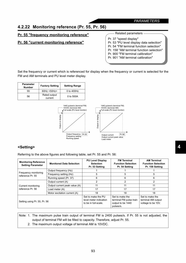
93
PARAMETERS
4
4.2.22 Monitoring reference (Pr. 55, Pr. 56)
Pr. 55 "frequency monitoring reference"
Pr. 56 "current monitoring reference"
Set the frequency or current which is referenced for display when the frequency or current is selected for theFM and AM terminals and PU level meter display.
<Setting>
Referring to the above figures and following table, set Pr. 55 and Pr. 56:
Parameter Number Factory Setting Setting Range
55 60Hz <50Hz> 0 to 400Hz
56 Rated output current 0 to 500A
Monitoring Reference Setting Parameter Monitored Data Selection
PU Level Display Selection
Pr. 53 Setting
FM TerminalFunction Selection
Pr. 54 Setting
AM TerminalFunction Selection
Pr. 158 Setting
Frequency monitoring reference Pr. 55
Output frequency (Hz) 1 1 1Frequency setting (Hz) 5 5 5Running speed (Pr. 37) 6 6 6
Current monitoring reference Pr. 56
Output current (A) 2 2 2Output current peak value (A) 11 11 11Load meter (A) 17 17 17Motor excitation current (A) 18 18 18
Setting using Pr. 55, Pr. 56
Set to make the PU level meter indication to be in full-scale.
Set to make the terminal FM pulse train output to be 1440 pulses/s.
Set to make the terminal AM output voltage to be 10V.
Note: 1. The maximum pulse train output of terminal FM is 2400 pulses/s. If Pr. 55 is not adjusted, theoutput of terminal FM will be filled to capacity. Therefore, adjust Pr. 55.
2. The maximum output voltage of terminal AM is 10VDC.
Related parameters
Pr. 37 "speed display"Pr. 53 "PU level display data selection"Pr. 54 "FM terminal function selection"Pr. 158 "AM terminal function selection"Pr. 900 "FM terminal calibration"Pr. 901 "AM terminal calibration"
Pr.56Pr.55
1440 pulses/s (terminal FM)10VDC (terminal AM)Full scale (PU level monitor)
Out
put o
r dis
play
Out
put o
r dis
play
Output frequencyFrequency settingRunning speed
Output currentOutput current peak valueLoad meter
1440 pulses/s (terminal FM)10VDC (terminal AM)Full scale (PU level monitor)
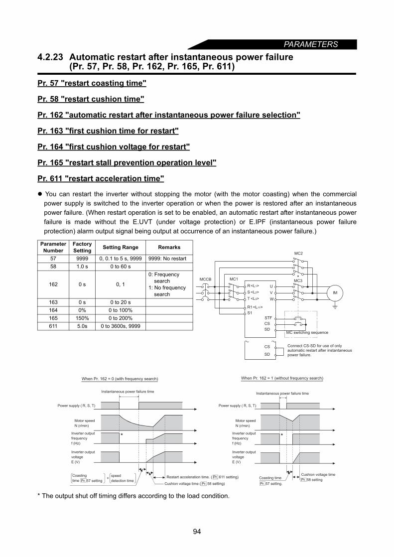
PARAMETERS
4.2.23 Automatic restart after instantaneous power failure(Pr. 57, Pr. 58, Pr. 162, Pr. 165, Pr. 611)
Pr. 57 "restart coasting time"
Pr. 58 "restart cushion time"
Pr. 162 "automatic restart after instantaneous power failure selection"
Pr. 163 "first cushion time for restart"
Pr. 164 "first cushion voltage for restart"
Pr. 165 "restart stall prevention operation level"
Pr. 611 "restart acceleration time"
You can restart the inverter without stopping the motor (with the motor coasting) when the commercialpower supply is switched to the inverter operation or when the power is restored after an instantaneouspower failure. (When restart operation is set to be enabled, an automatic restart after instantaneous powerfailure is made without the E.UVT (under voltage protection) or E.IPF (instantaneous power failureprotection) alarm output signal being output at occurrence of an instantaneous power failure.)
* The output shut off timing differs according to the load condition.
Parameter Number
Factory Setting Setting Range Remarks
57 9999 0, 0.1 to 5 s, 9999 9999: No restart58 1.0 s 0 to 60 s
162 0 s 0, 1
0: Frequency search
1: No frequency search
163 0 s 0 to 20 s164 0% 0 to 100%165 150% 0 to 200%611 5.0s 0 to 3600s, 9999
STF
IM
MCCB
CS
SD
CS
SD
MC1
MC2
MC3
W
V
U
Connect CS-SD for use of onlyautomatic restart after instantaneous power failure.
MC switching sequence
S1
R1<L11>
T
S
R<L1>
<L2>
<L3>
Instantaneous power failure time
*
Power supply ( R, S, T)
Motor speed
N (r/min)
Inverter output
frequency
f (Hz)
Inverter output
voltage
E (V)
Coasting
time
speed
detection time+
Pr. 57 setting
When Pr. 162 = 0 (with frequency search)
Coasting time
Pr. 57 setting.
Cushion voltage time
Pr. 58 setting
When Pr. 162 = 1 (without frequency search)
Instantaneous power failure time
Motor speed
N (r/min)
Inverter output
frequency
f (Hz)
Inverter output
voltage
E (V)
Power supply ( R, S, T)
Cushion voltage time ( Pr. 58 setting)
*
Restart acceleration time. ( Pr. 611 setting)
94

PARAMETERS
4
<Setting>Refer to the above figures and following table, and set the parameters:
Parameter Number Setting Description
162
0 Frequency search madeFrequency search is made after detection of an instantaneous power failure.
1No frequency searchIndependently of the motor coasting speed, the output voltage is gradually increased withthe frequency kept as preset.
57
00.4K to 1.5K 0.5 s coasting time
Generally use this setting.2.2K to 7.5K 1.0 s coasting time11K or more 3.0 s coasting time
0.1 to 5sWaiting time for inverter-triggered restart after power is restored from an instantaneous power failure. (Set this time between 0.1 s and 5 s according to the moment of inertia (J) and torque of the load.)
9999 No restart58 0 to 60 s
Normally the motor may be run with the factory settings. These values are adjustable to the load (moment of inertia, torque).
163 0 to 20 s164 0 to 100%165 0 to 200%
6110 to 3600s Set the acceleration time taken to reach the set frequency at a restart.
9999 Acceleration time at a restart is determined by the Pr. 7, Pr. 44 or Pr. 110 setting.
Note: 1. When restart operation is selected, UVT and IPF among the alarm output signals are not outputat occurrence of an instantaneous power failure.
2. If the inverter capacity is more than one rank higher than the motor capacity when Pr.162 = "0" (withspeed search), an overcurrent (OCT) alarm may take place, disabling the motor from starting.
3. When Pr. 57 ≠ 9999, the inverter will not run if the CS signal remain off.4. When Pr. 162 = "0", connection of two or more motors to one inverter will make the inverter
function improperly. (The inverter will not start properly.)5. When Pr. 162 = "0", the DC injection brake is operated instantly on detection of restarting speed.
Therefore, if the moment of inertia (J) of the load is small, the speed may reduce.6. When Pr. 162 = "1", the output frequency before an instantaneous power failure is stored and
output at the time of restart. If the power of the inverter control circuit is lost, the frequency beforean instantaneous power failure cannot be stored and the inverter will start at 0Hz.
7. The SU and FU signals are not output during restart but are output after the restart cushion timehas elapsed.
8. Changing the Pr. 21 "acceleration/deceleration time increments" setting will not change the Pr.611 setting increments.
9. The speed also increases according to the Pr. 611 setting after frequency search at the retry timeby the retry function. Refer to page 101 for retry function.
10.Note that when copying parameters to the inverter without this function, copying Pr. 611 = "9999"greatly increases acceleration time to 6553.5s.If accidentaly copied, set parameters again in the following procedure.1) Pr. 77 = "0" →"801"2) Pr. 611 = "6553.5" → "5"3) Pr. 77 = "801" → "0"
CAUTIONProvide mechanical interlocks for MC1 and MC2.The inverter will be damaged if power is entered into the inverter output section. When automatic restart after instantaneous power failure has been selected, the motorand machine will start suddenly (after the reset time has elapsed) after occurrence ofan instantaneous power failure. Stay away from the motor and machine.When you have selected automatic restart after instantaneous power failure, apply thesupplied CAUTION seals in easily visible places.
95
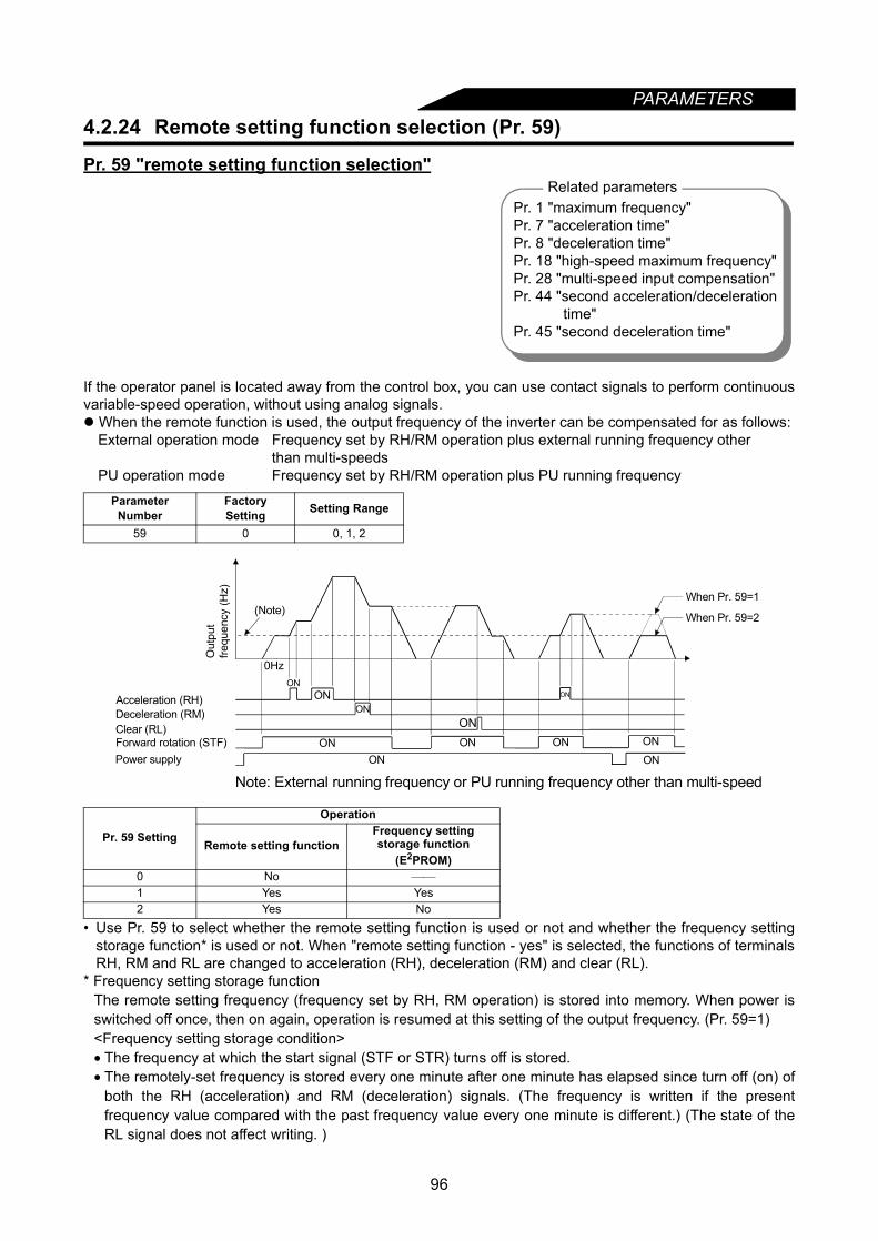
PARAMETERS
4.2.24 Remote setting function selection (Pr. 59)Pr. 59 "remote setting function selection"
If the operator panel is located away from the control box, you can use contact signals to perform continuousvariable-speed operation, without using analog signals. When the remote function is used, the output frequency of the inverter can be compensated for as follows:
External operation mode Frequency set by RH/RM operation plus external running frequency otherthan multi-speeds
PU operation mode Frequency set by RH/RM operation plus PU running frequency
• Use Pr. 59 to select whether the remote setting function is used or not and whether the frequency settingstorage function* is used or not. When "remote setting function - yes" is selected, the functions of terminalsRH, RM and RL are changed to acceleration (RH), deceleration (RM) and clear (RL).
* Frequency setting storage function The remote setting frequency (frequency set by RH, RM operation) is stored into memory. When power isswitched off once, then on again, operation is resumed at this setting of the output frequency. (Pr. 59=1)<Frequency setting storage condition>• The frequency at which the start signal (STF or STR) turns off is stored.• The remotely-set frequency is stored every one minute after one minute has elapsed since turn off (on) of
both the RH (acceleration) and RM (deceleration) signals. (The frequency is written if the presentfrequency value compared with the past frequency value every one minute is different.) (The state of theRL signal does not affect writing. )
ParameterNumber
FactorySetting Setting Range
59 0 0, 1, 2
Pr. 59 Setting
Operation
Remote setting functionFrequency setting storage function
(E2PROM)0 No
1 Yes Yes2 Yes No
Related parametersPr. 1 "maximum frequency"Pr. 7 "acceleration time"Pr. 8 "deceleration time"Pr. 18 "high-speed maximum frequency"Pr. 28 "multi-speed input compensation"Pr. 44 "second acceleration/deceleration
time"Pr. 45 "second deceleration time"
Deceleration (RM)Clear (RL)
Acceleration (RH)
Forward rotation (STF) ON ONPower supply ON
0Hz
(Note)
ONON
ONON
ON
ON
When Pr. 59=1
When Pr. 59=2
ON
ON
Out
put
frequ
ency
(Hz)
Note: External running frequency or PU running frequency other than multi-speed
96

PARAMETERS
4
Note: 1. The frequency can be varied by RH (acceleration) and RM (deceleration) between 0 and themaximum frequency (Pr. 1 or Pr. 18 setting).
2. When the acceleration or deceleration signal switches on, the set frequency varies according tothe slope set in Pr. 44 or Pr. 45. The output frequency acceleration/deceleration times are as setin Pr. 7 and Pr. 8, respectively. Therefore, the longer preset times are used to vary the actualoutput frequency.
3. If the start signal (STF or STR) is off, switching on the acceleration (RH) or deceleration (RM)signal varies the set frequency.
4. When making frequent on/off of the start signal and frequency changes by the RH and RMsignals, set the frequency setting storage signal (write setting values into the E2PROM) invalid(Pr. 59 = "2").When the signal is set valid (Pr. 59 = "1"), frequent writing of frequencies into the E2PROM willshorten the life of the E2PROM.
REMARKSThis function is invalid during jog operation and PID control operation.
• Even when the remotely-set frequency is cleared by turning on the RL (clear) signal after turn off (on) ofboth the RH and RM signals, the inverter operates at the remotely-set frequency stored in the lastoperation if power is reapplied before one minute has elapsed since turn off (on) of both the RH and RMsignals.
• When the remotely-set frequency is cleared by turning on the RL (clear) signal after turn off (on) of boththe RH and RM signals, the inverter operates at the frequency in the remotely-set frequency clearedstate if power is reapplied after one minute has elapsed since turn off (on) of both the RH and RMsignals.
CAUTION When selecting this function, re-set the maximum frequency according to the machine.
When the set frequency is 0
Clear (RL)
Acceleration (RH)
Forward rotation (STF)
Output
frequency
(Hz)
ON
Power supply ON
ON
ON
ON
ON
Within one minute
Remotely -set frequency
stored in the last operation
Deceleration (RM)OFF
Remotely -set frequency
stored in the last operation
Operation at a setfrequency of 0Hz
ONON
ON
ON
ONON
1 minute
OFF
Clear (RL)
Acceleration (RH)
Forward rotation (STF)
Outputfrequency
(Hz)
Power supply
More thanone minute
Remotely -set frequencystored in the last operation
Deceleration (RM)
97

PARAMETERS
4.2.25 Intelligent mode selection (Pr. 60)Pr. 60 "intelligent mode selection"
The inverter automatically sets appropriate parameters for operation. If you do not set the acceleration and deceleration times and V/F pattern, you can run the inverter as if
appropriate values had been set in the corresponding parameters. This operation mode is useful to startoperation immediately without making fine parameter settings.
If the intelligent operation mode has been selected, entry of the jog signal or RT (second functionselection) signal during an inverter stop starts ordinary operation, with priority given to jog operation orsecond function selection. After a start in the intelligent operation mode, neither the JOG signal nor the RTsignal is accepted.
<Setting>
Parameter Number Factory Setting Setting Range
60 0 0 to 8
Pr. 60 Setting Operation Mode Description Automatically Set
Parameters
0 Ordinary operation mode
1, 2Shortest acceleration/deceleration mode
Set to accelerate/decelerate the motor in the shortest time. The inverter makes acceleration/deceleration in the shortest time using its full capabilities. During deceleration, an insufficient brake capability may cause the regenerative overvoltage alarm (E.OV3)."1": Stall prevention operation level 150%"2": Stall prevention operation level 180%
Pr. 7, Pr. 8
3
Optimum acceleration/deceleration mode(Note 2, 4)
Optimum operation can be carried out by fully utilizing the inverter capabilities in the continuous rating range.Self-learning automatically sets the corresponding parameters so that the average current during acceleration/deceleration is equal to the rated current. Appropriate for applications where the load will not vary by a large amount.
Pr. 0, Pr. 7, Pr. 8
4 Energy-saving mode (Note 3, 5)
Tunes the output voltage online to minimize the inverter output power during constant-speed operation.Appropriate for energy-saving applications such as fan and pump operation.
Output voltage
5, 6 Elevator mode(Note 3)
Automatically controls the inverter output voltage to deliver the maximum torque in both the driving and regenerative modes. Appropriate for a counterbalanced elevator."5": Stall prevention operation level 150%"6": Stall prevention operation level 180%
Pr. 0, Pr. 13, Pr. 19
7
Brake sequence mode
Mechanicalbrake opening completion signal input
This function causes the inverter to output the mechanical brake operation timing signal for elevating application. For function details and related parameter setting, refer to Pr. 278 to Pr. 285 (brake sequence functions).
8
Mechanicalbrake opening completion signal not input
Related parametersPr. 0 "torque boost"Pr. 7 "acceleration time"Pr. 8 "deceleration time"Pr. 13 "starting frequency"Pr. 19 "base frequency voltage"Pr. 80, Pr. 81 (advanced magnetic flux vector control)Pr. 278 to Pr. 285 (brake sequence functions)
98
PARAMETERS
4
Note: 1. When more accurate control is required for your application, set the other parameters asappropriate.
2. Because of the learning system, this control is not valid at the first time in the optimumacceleration/deceleration mode. Also, this mode is only valid for frequency setting of 30.01Hz ormore.
3. When the advanced magnetic flux vector control has been selected using Pr. 80 and Pr. 81, thesettings of the energy-saving mode and elevator mode are ignored. (Advanced magnetic fluxvector control has higher priority.)
4. If an overvoltage (OV3) trip has occurred during operation in the optimum acceleration/deceleration mode (setting "3"), re-set Pr. 8 "deceleration time" to a larger value and restartoperation in this mode.
5. When the "energy-saving mode" (setting "4") is used to decelerate the motor to a stop, thedeceleration time may be longer than the preset value. Also, overvoltage is more likely to occur inthis mode as compared to the constant-torque load characteristics, therefore set the decelerationtime to a larger value.
99
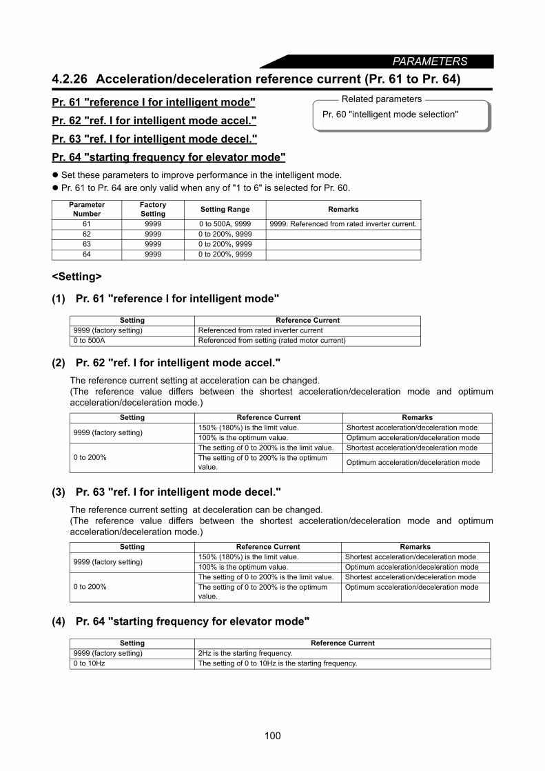
100
PARAMETERS4.2.26 Acceleration/deceleration reference current (Pr. 61 to Pr. 64)
Pr. 61 "reference I for intelligent mode"Pr. 62 "ref. I for intelligent mode accel."Pr. 63 "ref. I for intelligent mode decel."Pr. 64 "starting frequency for elevator mode" Set these parameters to improve performance in the intelligent mode. Pr. 61 to Pr. 64 are only valid when any of "1 to 6" is selected for Pr. 60.
<Setting>
(1) Pr. 61 "reference I for intelligent mode"
(2) Pr. 62 "ref. I for intelligent mode accel."The reference current setting at acceleration can be changed.(The reference value differs between the shortest acceleration/deceleration mode and optimumacceleration/deceleration mode.)
(3) Pr. 63 "ref. I for intelligent mode decel."The reference current setting at deceleration can be changed.(The reference value differs between the shortest acceleration/deceleration mode and optimumacceleration/deceleration mode.)
(4) Pr. 64 "starting frequency for elevator mode"
Parameter Number
FactorySetting Setting Range Remarks
61 9999 0 to 500A, 9999 9999: Referenced from rated inverter current.62 9999 0 to 200%, 999963 9999 0 to 200%, 999964 9999 0 to 200%, 9999
Setting Reference Current9999 (factory setting) Referenced from rated inverter current0 to 500A Referenced from setting (rated motor current)
Setting Reference Current Remarks
9999 (factory setting)150% (180%) is the limit value. Shortest acceleration/deceleration mode100% is the optimum value. Optimum acceleration/deceleration mode
0 to 200%The setting of 0 to 200% is the limit value. Shortest acceleration/deceleration modeThe setting of 0 to 200% is the optimum value. Optimum acceleration/deceleration mode
Setting Reference Current Remarks
9999 (factory setting)150% (180%) is the limit value. Shortest acceleration/deceleration mode100% is the optimum value. Optimum acceleration/deceleration mode
0 to 200%The setting of 0 to 200% is the limit value. Shortest acceleration/deceleration modeThe setting of 0 to 200% is the optimum value.
Optimum acceleration/deceleration mode
Setting Reference Current9999 (factory setting) 2Hz is the starting frequency.0 to 10Hz The setting of 0 to 10Hz is the starting frequency.
Related parameters
Pr. 60 "intelligent mode selection"
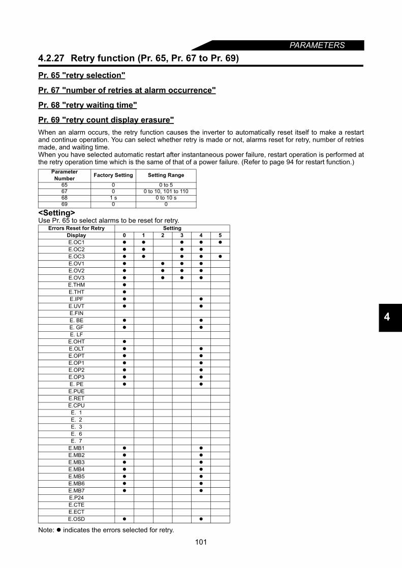
PARAMETERS
4
4.2.27 Retry function (Pr. 65, Pr. 67 to Pr. 69)
Pr. 65 "retry selection"
Pr. 67 "number of retries at alarm occurrence"
Pr. 68 "retry waiting time"
Pr. 69 "retry count display erasure"When an alarm occurs, the retry function causes the inverter to automatically reset itself to make a restartand continue operation. You can select whether retry is made or not, alarms reset for retry, number of retriesmade, and waiting time.When you have selected automatic restart after instantaneous power failure, restart operation is performed atthe retry operation time which is the same of that of a power failure. (Refer to page 94 for restart function.)
<Setting>Use Pr. 65 to select alarms to be reset for retry.
Note: indicates the errors selected for retry.
Parameter Number Factory Setting Setting Range
65 0 0 to 567 0 0 to 10, 101 to 11068 1 s 0 to 10 s69 0 0
Errors Reset for Retry SettingDisplay 0 1 2 3 4 5E.OC1
E.OC2
E.OC3
E.OV1
E.OV2
E.OV3
E.THM
E.THT
E.IPF
E.UVT
E.FINE. BE
E. GF
E. LFE.OHT
E.OLT
E.OPT
E.OP1
E.OP2
E.OP3
E. PE
E.PUEE.RETE.CPUE. 1E. 2E. 3E. 6E. 7
E.MB1
E.MB2
E.MB3
E.MB4
E.MB5
E.MB6
E.MB7
E.P24E.CTEE.ECTE.OSD
101

PARAMETERS
• Use Pr. 67 to set the number of retries at alarm occurrence.• Use Pr. 68 to set the waiting time from when an inverter alarm occurs until a restart in the range 0 to 10s.• Reading the Pr. 69 value provides the cumulative number of successful restart times made by retry. The
setting of "0" erases the cumulative number of times.
Pr. 67 Setting Number of Retries Alarm Signal Output0 Retry is not made.
1 to 10 1 to 10 times Not output.101 to 110 1 to 10 times Output
Note: 1. The cumulative number in Pr. 69 is incremented by "1" when retry operation is regarded assuccessful, i.e. when normal operation is continued without any alarm occurring during a periodmore than four times longer than the time set in Pr. 68.
2. If alarms occur consecutively within a period four times longer than the above waiting time, theoperation panel (FR-DU04) may show data different from the most recent data or the parameterunit (FR-PU04) may show data different from the first retry data. The data stored as the errorreset for retry is only that of the alarm which occurred the first time.
3. When an inverter alarm is reset at the restart time, the stored data of the electronic overcurrentprotection, regeneration converter duty, etc. are not cleared. (Different from the power-on reset.)
CAUTION When you have selected the retry function, stay away from the motor and machine unless required. They will start suddenly (after the reset time has elapsed) after occurrence of an alarm.When you have selected the retry function, apply the supplied CAUTION seals in easily visible places.
Pr. 66 Refer to Pr. 22.
Pr. 70 Refer to Pr. 30.
102

103
PARAMETERS
4
4.2.28 Applied motor (Pr. 71)
Pr. 71 "applied motor"
Set the motor used.
<Setting>
• Refer to the following list and set this parameter accordingto the motor used.
• For the 5.5K and 7.5K, the Pr. 0 and Pr. 12 settings are automatically changed depending on the Pr. 71setting.
Parameter Number
Factory Setting Setting Range
71 0 0 to 8, 13 to 18, 20, 23, 24
Pr. 71 Setting Thermal Characteristics of Electronic Overcurrent Protection
Motor
Standard ConstantTorque
0 Thermal characteristics of a standard motor
1 Thermal characteristics of a Mitsubishi constant-torque motor
2 Thermal characteristics matching a standard motor5-point flexible V/F characteristics (Refer to page 125)
20 Thermal characteristics for advanced magnetic flux vector control of the Mitsubishi standard motor SF-JR4P (1.5kW (2HP) or less)
3 Standard motor
Select "offline auto tuning setting".
13 Constant-torque motor
23 Mitsubishi general-purpose motor SF-JR4P (1.5kW (2HP) or less)
4 Standard motorRead auto tuning data, settings can be changed.
14 Auto tuning data can be read or set anew.
24 Mitsubishi general-purpose motor SF-JR4P (1.5kW (2HP) or less)
5 Standard motor Star connectionMotor constants can be entered directly.
15 Constant-torque motor
6 Standard motor Delta connection
16 Constant-torque motor
7 Standard motor Standard motor Direct motor constant entry and offline auto tuning
17 Constant-torque motor
8 Standard motor Delta connection
18 Constant-torque motor
Pr. 71 0, 2, 3 to 8, 20, 23, 24 1, 13 to 18Pr. 0 3% 2%
Pr. 12 4% 2%
Note: 1. When "8888" or "9999" is set in Pr. 19, "2" cannot be set in Pr. 71. To set "2" in Pr. 71, set theappropriate value (other than "8888" and "9999") in Pr. 19.
2. When "2" is set in Pr. 71, Pr. 100 to Pr. 109 are displayed on the parameter unit (FR-PU04). Inother settings, if any of Pr. 100 to Pr. 109 settings is changed, the new setting is not displayed inthe "Default parameter list" and "Set parameter list".
3. Refer to Pr. 96 for offline auto tuning.4. Set any of "3, 7, 8, 13, 17 and 18" to perform offline auto tuning.
CAUTIONSet this parameter correctly according to the motor used.Incorrect setting may cause the motor to overheat and burn.
Related parametersPr. 0 "torque boost"Pr. 12 "DC injection brake voltage"Pr. 19 "base frequency voltage"Pr. 60 "intelligent mode selection"Pr. 80 "motor capacity"Pr. 81 "number of motor poles"Pr. 96 "auto tuning setting/status"Pr. 100 to Pr. 109 (V/F frequency/voltage)
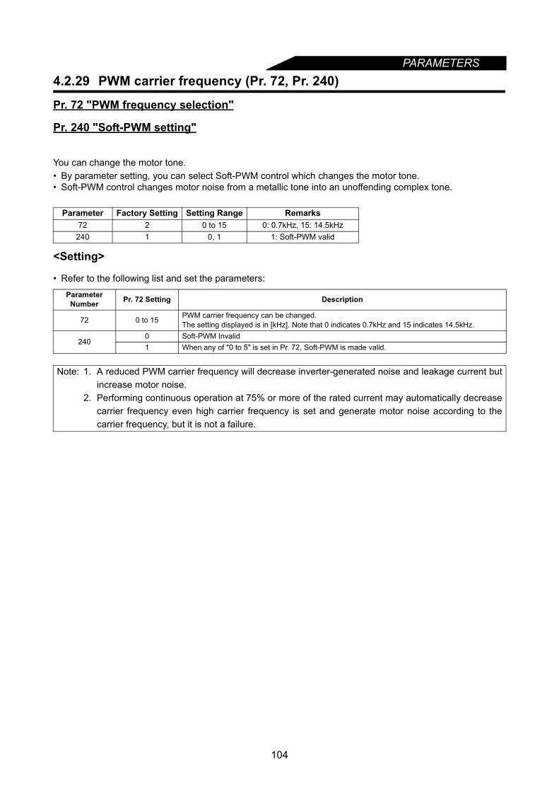
104
PARAMETERS4.2.29 PWM carrier frequency (Pr. 72, Pr. 240)
Pr. 72 "PWM frequency selection"
Pr. 240 "Soft-PWM setting"
You can change the motor tone.• By parameter setting, you can select Soft-PWM control which changes the motor tone.• Soft-PWM control changes motor noise from a metallic tone into an unoffending complex tone.
<Setting>
• Refer to the following list and set the parameters:
Parameter Factory Setting Setting Range Remarks72 2 0 to 15 0: 0.7kHz, 15: 14.5kHz
240 1 0, 1 1: Soft-PWM valid
Parameter Number Pr. 72 Setting Description
72 0 to 15 PWM carrier frequency can be changed.The setting displayed is in [kHz]. Note that 0 indicates 0.7kHz and 15 indicates 14.5kHz.
2400 Soft-PWM Invalid1 When any of "0 to 5" is set in Pr. 72, Soft-PWM is made valid.
Note: 1. A reduced PWM carrier frequency will decrease inverter-generated noise and leakage current butincrease motor noise.
2. Performing continuous operation at 75% or more of the rated current may automatically decreasecarrier frequency even high carrier frequency is set and generate motor noise according to thecarrier frequency, but it is not a failure.
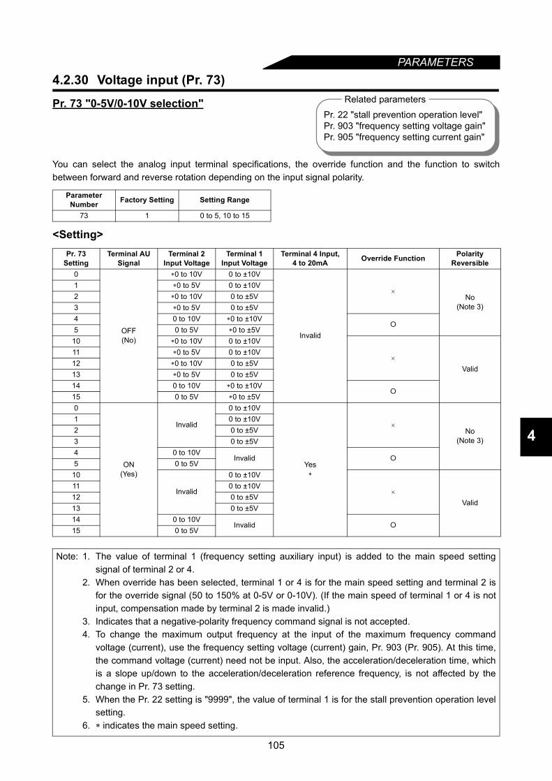
105
PARAMETERS
4
4.2.30 Voltage input (Pr. 73)
Pr. 73 "0-5V/0-10V selection"
You can select the analog input terminal specifications, the override function and the function to switchbetween forward and reverse rotation depending on the input signal polarity.
<Setting>
Parameter Number Factory Setting Setting Range
73 1 0 to 5, 10 to 15
Pr. 73 Setting
Terminal AU Signal
Terminal 2 Input Voltage
Terminal 1 Input Voltage
Terminal 4 Input, 4 to 20mA Override Function Polarity
Reversible0
OFF(No)
∗0 to 10V 0 to ±10V
Invalid
×
No(Note 3)
1 ∗0 to 5V 0 to ±10V2 ∗0 to 10V 0 to ±5V3 ∗0 to 5V 0 to ±5V4 0 to 10V ∗0 to ±10V
5 0 to 5V ∗0 to ±5V
10 ∗0 to 10V 0 to ±10V
×
Valid
11 ∗0 to 5V 0 to ±10V12 ∗0 to 10V 0 to ±5V13 ∗0 to 5V 0 to ±5V14 0 to 10V ∗0 to ±10V
15 0 to 5V ∗0 to ±5V0
ON(Yes)
Invalid
0 to ±10V
Yes∗
×
No(Note 3)
1 0 to ±10V2 0 to ±5V3 0 to ±5V4 0 to 10V
Invalid 5 0 to 5V
10
Invalid
0 to ±10V
×
Valid
11 0 to ±10V12 0 to ±5V13 0 to ±5V14 0 to 10V
Invalid 15 0 to 5V
Note: 1. The value of terminal 1 (frequency setting auxiliary input) is added to the main speed settingsignal of terminal 2 or 4.
2. When override has been selected, terminal 1 or 4 is for the main speed setting and terminal 2 isfor the override signal (50 to 150% at 0-5V or 0-10V). (If the main speed of terminal 1 or 4 is notinput, compensation made by terminal 2 is made invalid.)
3. Indicates that a negative-polarity frequency command signal is not accepted.4. To change the maximum output frequency at the input of the maximum frequency command
voltage (current), use the frequency setting voltage (current) gain, Pr. 903 (Pr. 905). At this time,the command voltage (current) need not be input. Also, the acceleration/deceleration time, whichis a slope up/down to the acceleration/deceleration reference frequency, is not affected by thechange in Pr. 73 setting.
5. When the Pr. 22 setting is "9999", the value of terminal 1 is for the stall prevention operation levelsetting.
6. ∗ indicates the main speed setting.
Related parametersPr. 22 "stall prevention operation level"Pr. 903 "frequency setting voltage gain"Pr. 905 "frequency setting current gain"
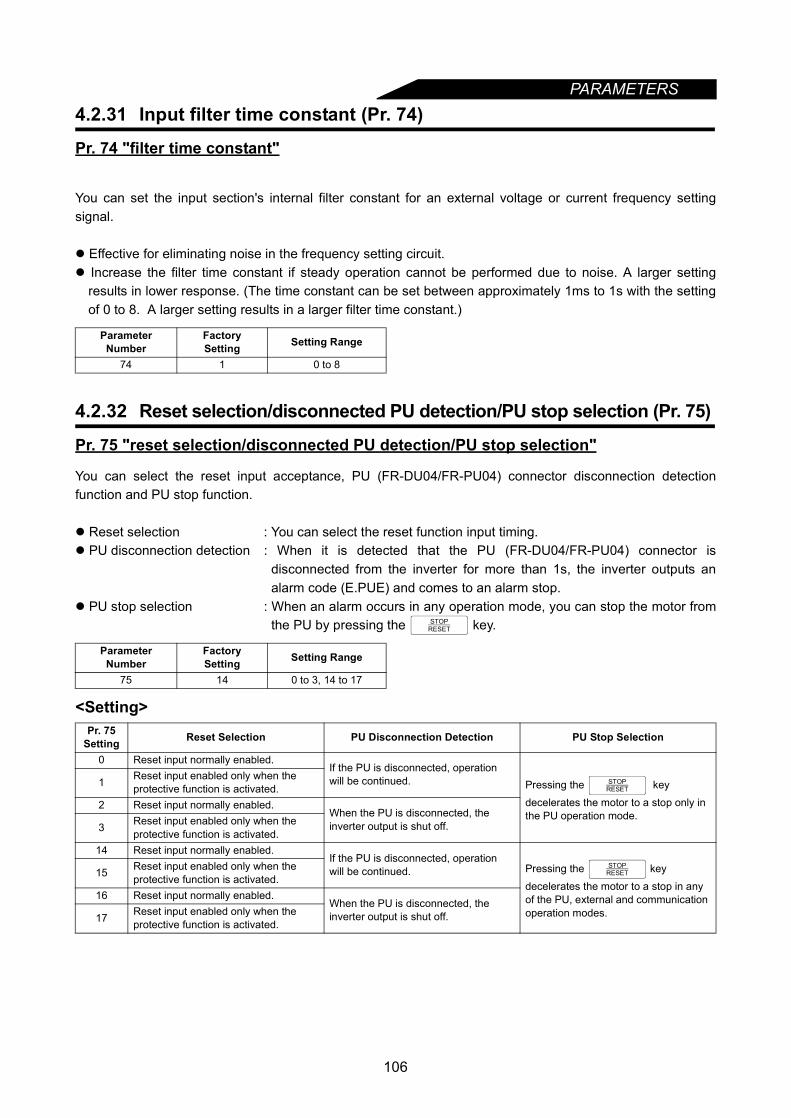
PARAMETERS
4.2.31 Input filter time constant (Pr. 74)Pr. 74 "filter time constant"
You can set the input section's internal filter constant for an external voltage or current frequency settingsignal.
Effective for eliminating noise in the frequency setting circuit. Increase the filter time constant if steady operation cannot be performed due to noise. A larger setting
results in lower response. (The time constant can be set between approximately 1ms to 1s with the settingof 0 to 8. A larger setting results in a larger filter time constant.)
4.2.32 Reset selection/disconnected PU detection/PU stop selection (Pr. 75)
Pr. 75 "reset selection/disconnected PU detection/PU stop selection"
You can select the reset input acceptance, PU (FR-DU04/FR-PU04) connector disconnection detectionfunction and PU stop function.
Reset selection : You can select the reset function input timing. PU disconnection detection : When it is detected that the PU (FR-DU04/FR-PU04) connector is
disconnected from the inverter for more than 1s, the inverter outputs analarm code (E.PUE) and comes to an alarm stop.
PU stop selection : When an alarm occurs in any operation mode, you can stop the motor fromthe PU by pressing the key.
<Setting>
Parameter Number
FactorySetting Setting Range
74 1 0 to 8
Parameter Number
FactorySetting Setting Range
75 14 0 to 3, 14 to 17
Pr. 75 Setting Reset Selection PU Disconnection Detection PU Stop Selection
0 Reset input normally enabled.If the PU is disconnected, operation will be continued. Pressing the key
decelerates the motor to a stop only in the PU operation mode.
1 Reset input enabled only when the protective function is activated.
2 Reset input normally enabled.When the PU is disconnected, the inverter output is shut off.3 Reset input enabled only when the
protective function is activated.14 Reset input normally enabled.
If the PU is disconnected, operation will be continued. Pressing the key
decelerates the motor to a stop in any of the PU, external and communication operation modes.
15 Reset input enabled only when the protective function is activated.
16 Reset input normally enabled.When the PU is disconnected, the inverter output is shut off.17 Reset input enabled only when the
protective function is activated.
STOPRESET
STOPRESET
STOPRESET
106
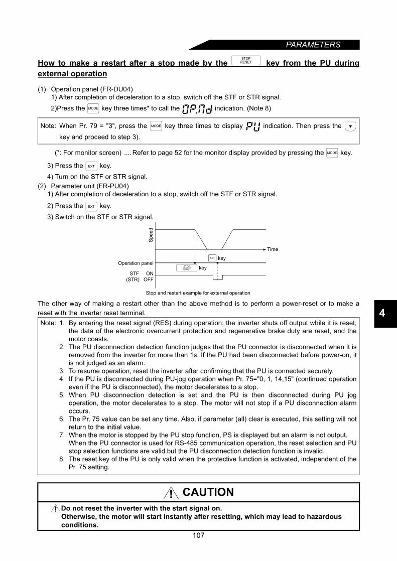
PARAMETERS
4
How to make a restart after a stop made by the key from the PU duringexternal operation
(1) Operation panel (FR-DU04)1) After completion of deceleration to a stop, switch off the STF or STR signal.2)Press the key three times* to call the indication. (Note 8)
(*: For monitor screen) ....Refer to page 52 for the monitor display provided by pressing the key.
3) Press the key.4) Turn on the STF or STR signal.
(2) Parameter unit (FR-PU04)1) After completion of deceleration to a stop, switch off the STF or STR signal.
2) Press the key.
3) Switch on the STF or STR signal.
The other way of making a restart other than the above method is to perform a power-reset or to make areset with the inverter reset terminal.
Note: When Pr. 79 = "3", press the key three times to display indication. Then press the
key and proceed to step 3).
Note: 1. By entering the reset signal (RES) during operation, the inverter shuts off output while it is reset,the data of the electronic overcurrent protection and regenerative brake duty are reset, and themotor coasts.
2. The PU disconnection detection function judges that the PU connector is disconnected when it isremoved from the inverter for more than 1s. If the PU had been disconnected before power-on, itis not judged as an alarm.
3. To resume operation, reset the inverter after confirming that the PU is connected securely.4. If the PU is disconnected during PU-jog operation when Pr. 75="0, 1, 14,15" (continued operation
even if the PU is disconnected), the motor decelerates to a stop.5. When PU disconnection detection is set and the PU is then disconnected during PU jog
operation, the motor decelerates to a stop. The motor will not stop if a PU disconnection alarmoccurs.
6. The Pr. 75 value can be set any time. Also, if parameter (all) clear is executed, this setting will notreturn to the initial value.
7. When the motor is stopped by the PU stop function, PS is displayed but an alarm is not output.When the PU connector is used for RS-485 communication operation, the reset selection and PUstop selection functions are valid but the PU disconnection detection function is invalid.
8. The reset key of the PU is only valid when the protective function is activated, independent of thePr. 75 setting.
CAUTIONDo not reset the inverter with the start signal on.Otherwise, the motor will start instantly after resetting, which may lead to hazardous conditions.
STOPRESET
MODE
MODE
MODE
EXT
EXT
STF ON(STR) OFF
Spee
d
Operation panel
Time
Stop and restart example for external operation
keySET
keySTOPRESET
107

PARAMETERS
4.2.33 Alarm code output selection (Pr. 76)Pr. 76 "alarm code output selection"
When an alarm occurs, its code can be output as a 4-bit digital signal from the open collector outputterminals. When programmed operation has been selected, this parameter also serves to output a groupoperation signal.The alarm code can be read by a programmable controller, etc. to show its remedy on a display. Also youcan look at the progress of programmed operation.
<Setting>
•Alarm code output
Parameter Number Factory Setting Setting Range
76 0 0 to 3
Pr. 76 SettingOutput Terminals
SU IPF OL FU0 Alarm code is not output. (Depends on Pr. 190 to Pr. 195).1 Alarm code bit 3 Alarm code bit 2 Alarm code bit 1 Alarm code bit 0
2 When an alarm occurs, an alarm code signal is output. (Output signal is the same as in 1.)When operation is normal, an operation status signal is output. (Output signal is the same as in 0.)
3(during programmed
operation)Output at time-out During group 3 operation During group 2 operation During group 1 operation
Note: 1. For alarm code definitions, refer to page 202.2. The Pr. 76 setting overrides the Pr. 190 to Pr. 195 settings. Therefore, if you assign other signals
to output terminals SU, IPF, OL and FU using Pr. 190 to Pr. 195, these terminals provide theoutput signals as listed above when any of "1 to 3" is set in Pr. 76. This should be noted whenusing the functions which use the output signals to exercise control.
Related parametersPr. 79 "operation mode selection"Pr. 190 to Pr. 195 (output terminal function selection)Pr. 200 to Pr. 231 (programmed operation)
Example: When using the brake sequence functions (Pr. 278 to Pr. 285), assign the brakeopening request signal (BOF) to the RUN terminal by setting "20" in Pr. 190.
108

109
PARAMETERS
4
4.2.34 Parameter write disable selection (Pr. 77)
Pr. 77 "parameter write disable selection"
You can select between write-enable and disable for parameters. This function is used to prevent parametervalues from being rewritten by accident.
<Setting>
Parameter Number
FactorySetting Setting Range
77 0 0, 1, 2
Pr. 77 Setting Function
0 Write enabled during a stop only.Parameter values may only be written during a stop in the PU operation mode. (Note 1)
1 Write disabled.Values of Pr. 22, Pr. 75, Pr. 77 and Pr. 79 "operation mode selection" can be written.
2 Write enabled even during operation.
Note: 1. The shaded parameters in the parameter list can be set at any time. (Refer to page 62.)(Pr. 72 and Pr. 240 values cannot be set during external operation.)
2. If Pr. 77 = "2", the values of the following parameters cannot be written during operation. Stopoperation when changing their parameter settings.
3. By setting "1" in Pr. 77, the following clear operations can be inhibited:•Parameter clear•All clear•User clear
Pr. 79 "operation mode selection"Related parameters
Parameter Number Name
23 Stall prevention operation level compensation factor at double speed
48 Second stall prevention operation current49 Second stall prevention operation frequency60 Intelligent mode selection61 Reference current
66 Stall prevention operation reduction starting frequency
71 Applied motor79 Operation mode selection80 Motor capacity81 Number of motor poles83 Rated motor voltage84 Rated motor frequency95 Advanced mode selection96 Auto tuning setting/status
100 V/F1 (first frequency)101 V/F1 (first frequency voltage)102 V/F2 (second frequency)103 V/F2 (second frequency voltage)104 V/F3 (third frequency)105 V/F3 (third frequency voltage)106 V/F4 (fourth frequency)107 V/F4 (fourth frequency voltage)
108 V/F5 (fifth frequency)109 V/F5 (fifth frequency voltage)
135 Commercial power supply-inverter switchover sequence output terminal selection
136 MC switchover interlock time137 Start waiting time
138 Commercial power supply-inverter switchover selection at alarm occurrenc
139 Automatic inverter-commercial power supply switchover frequency
180 RL terminal function selection181 RM terminal function selection182 RH terminal function selection183 RT terminal function selection184 AU terminal function selection185 JOG terminal function selection186 CS terminal function selection190 RUN terminal function selection191 SU terminal function selection192 IPF terminal function selection193 OL terminal function selection194 FU terminal function selection195 A, B, C terminal function selection
Parameter Number Name

110
PARAMETERS4.2.35 Reverse rotation prevention selection (Pr. 78)
Pr. 78 "reverse rotation prevention selection"
This function can prevent any reverse rotation fault resulting from the incorrect input of the start signal.
Used for a machine which runs only in one direction, e.g. fan, pump.(The setting of this function is valid for the PU, external and communication operations.)
<Setting>
Parameter Number
FactorySetting Setting Range
78 0 0, 1, 2
Pr. 78 Setting Function0 Both forward and reverse rotations allowed1 Reverse rotation disallowed2 Forward rotation disallowed
Related parametersPr. 79 "operation mode selection"
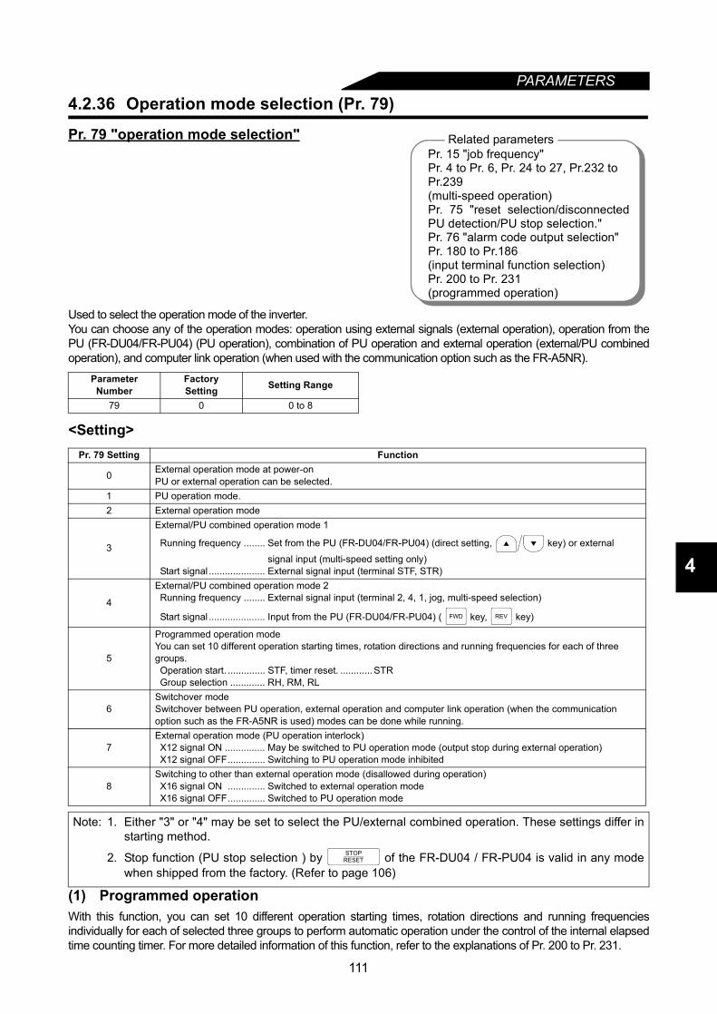
PARAMETERS
4
4.2.36 Operation mode selection (Pr. 79)
Pr. 79 "operation mode selection"
Used to select the operation mode of the inverter.You can choose any of the operation modes: operation using external signals (external operation), operation from thePU (FR-DU04/FR-PU04) (PU operation), combination of PU operation and external operation (external/PU combinedoperation), and computer link operation (when used with the communication option such as the FR-A5NR).
<Setting>
(1) Programmed operationWith this function, you can set 10 different operation starting times, rotation directions and running frequenciesindividually for each of selected three groups to perform automatic operation under the control of the internal elapsedtime counting timer. For more detailed information of this function, refer to the explanations of Pr. 200 to Pr. 231.
Parameter Number
FactorySetting Setting Range
79 0 0 to 8
Pr. 79 Setting Function
0 External operation mode at power-onPU or external operation can be selected.
1 PU operation mode.2 External operation mode
3
External/PU combined operation mode 1
Running frequency ........ Set from the PU (FR-DU04/FR-PU04) (direct setting, key) or external
signal input (multi-speed setting only)Start signal ..................... External signal input (terminal STF, STR)
4
External/PU combined operation mode 2Running frequency ........ External signal input (terminal 2, 4, 1, jog, multi-speed selection)
Start signal ..................... Input from the PU (FR-DU04/FR-PU04) ( key, key)
5
Programmed operation modeYou can set 10 different operation starting times, rotation directions and running frequencies for each of three groups.Operation start. .............. STF, timer reset. ............ STRGroup selection ............. RH, RM, RL
6Switchover modeSwitchover between PU operation, external operation and computer link operation (when the communication option such as the FR-A5NR is used) modes can be done while running.
7External operation mode (PU operation interlock)X12 signal ON ............... May be switched to PU operation mode (output stop during external operation)X12 signal OFF.............. Switching to PU operation mode inhibited
8Switching to other than external operation mode (disallowed during operation)X16 signal ON .............. Switched to external operation modeX16 signal OFF.............. Switched to PU operation mode
Note: 1. Either "3" or "4" may be set to select the PU/external combined operation. These settings differ instarting method.
2. Stop function (PU stop selection ) by of the FR-DU04 / FR-PU04 is valid in any modewhen shipped from the factory. (Refer to page 106)
Related parametersPr. 15 "job frequency"Pr. 4 to Pr. 6, Pr. 24 to 27, Pr.232 toPr.239(multi-speed operation)Pr. 75 "reset selection/disconnectedPU detection/PU stop selection."Pr. 76 "alarm code output selection"Pr. 180 to Pr.186(input terminal function selection)Pr. 200 to Pr. 231(programmed operation)
FWD REV
STOPRESET
111
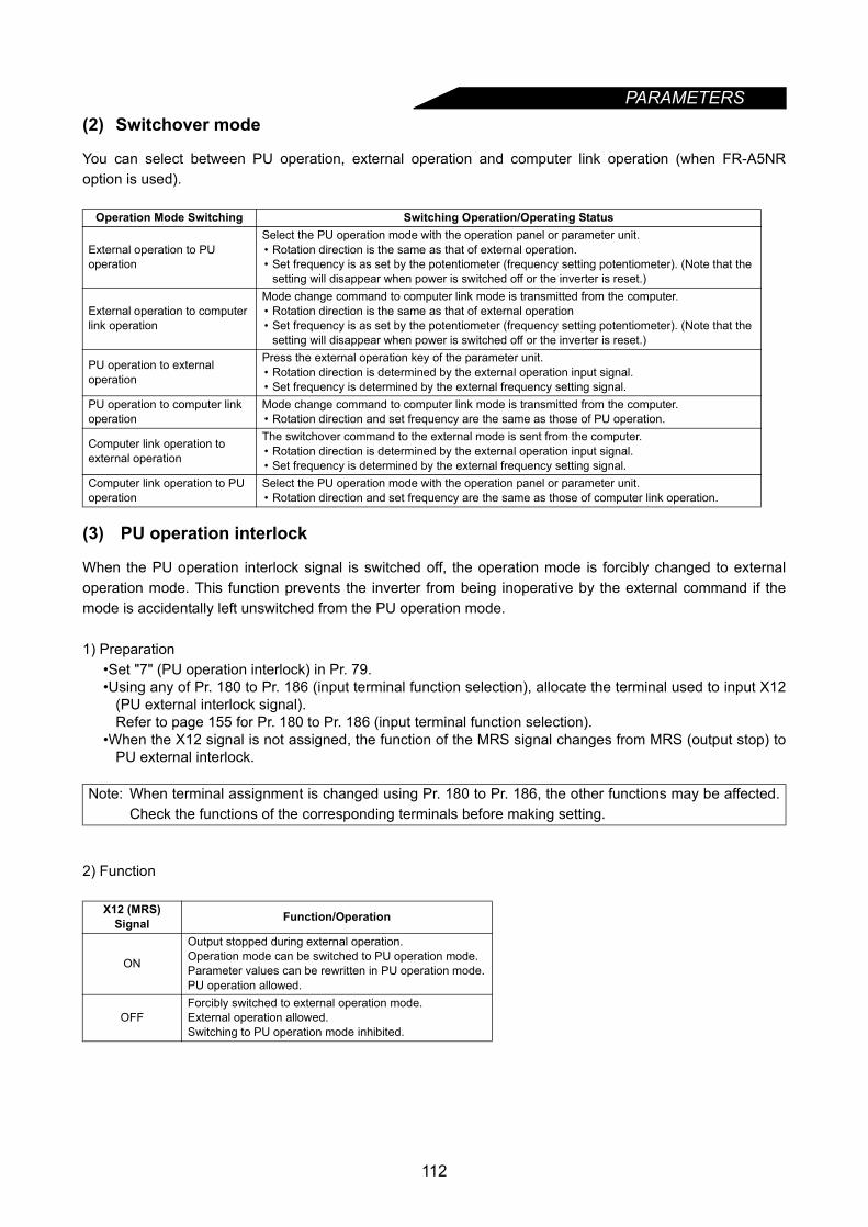
PARAMETERS
(2) Switchover modeYou can select between PU operation, external operation and computer link operation (when FR-A5NRoption is used).
(3) PU operation interlock
When the PU operation interlock signal is switched off, the operation mode is forcibly changed to externaloperation mode. This function prevents the inverter from being inoperative by the external command if themode is accidentally left unswitched from the PU operation mode.
1) Preparation•Set "7" (PU operation interlock) in Pr. 79.•Using any of Pr. 180 to Pr. 186 (input terminal function selection), allocate the terminal used to input X12
(PU external interlock signal).Refer to page 155 for Pr. 180 to Pr. 186 (input terminal function selection).
•When the X12 signal is not assigned, the function of the MRS signal changes from MRS (output stop) toPU external interlock.
2) Function
Operation Mode Switching Switching Operation/Operating Status
External operation to PU operation
Select the PU operation mode with the operation panel or parameter unit.• Rotation direction is the same as that of external operation.• Set frequency is as set by the potentiometer (frequency setting potentiometer). (Note that the
setting will disappear when power is switched off or the inverter is reset.)
External operation to computer link operation
Mode change command to computer link mode is transmitted from the computer.• Rotation direction is the same as that of external operation• Set frequency is as set by the potentiometer (frequency setting potentiometer). (Note that the
setting will disappear when power is switched off or the inverter is reset.)
PU operation to external operation
Press the external operation key of the parameter unit.• Rotation direction is determined by the external operation input signal.• Set frequency is determined by the external frequency setting signal.
PU operation to computer link operation
Mode change command to computer link mode is transmitted from the computer.• Rotation direction and set frequency are the same as those of PU operation.
Computer link operation to external operation
The switchover command to the external mode is sent from the computer.• Rotation direction is determined by the external operation input signal.• Set frequency is determined by the external frequency setting signal.
Computer link operation to PU operation
Select the PU operation mode with the operation panel or parameter unit.• Rotation direction and set frequency are the same as those of computer link operation.
Note: When terminal assignment is changed using Pr. 180 to Pr. 186, the other functions may be affected.Check the functions of the corresponding terminals before making setting.
X12 (MRS) Signal Function/Operation
ON
Output stopped during external operation.Operation mode can be switched to PU operation mode.Parameter values can be rewritten in PU operation mode.PU operation allowed.
OFFForcibly switched to external operation mode.External operation allowed.Switching to PU operation mode inhibited.
112
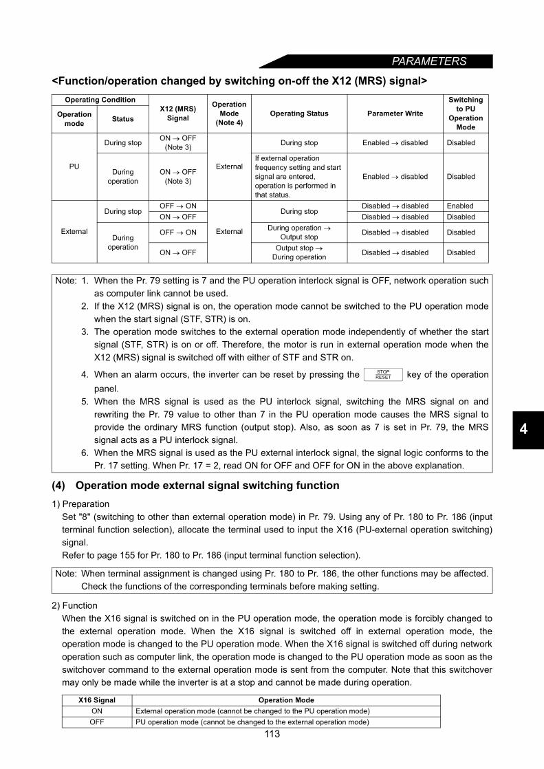
PARAMETERS
4
<Function/operation changed by switching on-off the X12 (MRS) signal>
(4) Operation mode external signal switching function1) Preparation
Set "8" (switching to other than external operation mode) in Pr. 79. Using any of Pr. 180 to Pr. 186 (inputterminal function selection), allocate the terminal used to input the X16 (PU-external operation switching)signal.Refer to page 155 for Pr. 180 to Pr. 186 (input terminal function selection).
2) FunctionWhen the X16 signal is switched on in the PU operation mode, the operation mode is forcibly changed tothe external operation mode. When the X16 signal is switched off in external operation mode, theoperation mode is changed to the PU operation mode. When the X16 signal is switched off during networkoperation such as computer link, the operation mode is changed to the PU operation mode as soon as theswitchover command to the external operation mode is sent from the computer. Note that this switchovermay only be made while the inverter is at a stop and cannot be made during operation.
Operating ConditionX12 (MRS)
Signal
Operation Mode
(Note 4)Operating Status Parameter Write
Switching to PU
Operation Mode
Operation mode Status
PU
During stop ON → OFF(Note 3)
External
During stop Enabled → disabled Disabled
During operation
ON → OFF(Note 3)
If external operation frequency setting and start signal are entered, operation is performed in that status.
Enabled → disabled Disabled
External
During stopOFF → ON
External
During stopDisabled → disabled Enabled
ON → OFF Disabled → disabled Disabled
During operation
OFF → ON During operation → Output stop Disabled → disabled Disabled
ON → OFF Output stop →During operation Disabled → disabled Disabled
Note: 1. When the Pr. 79 setting is 7 and the PU operation interlock signal is OFF, network operation suchas computer link cannot be used.
2. If the X12 (MRS) signal is on, the operation mode cannot be switched to the PU operation modewhen the start signal (STF, STR) is on.
3. The operation mode switches to the external operation mode independently of whether the startsignal (STF, STR) is on or off. Therefore, the motor is run in external operation mode when theX12 (MRS) signal is switched off with either of STF and STR on.
4. When an alarm occurs, the inverter can be reset by pressing the key of the operationpanel.
5. When the MRS signal is used as the PU interlock signal, switching the MRS signal on andrewriting the Pr. 79 value to other than 7 in the PU operation mode causes the MRS signal toprovide the ordinary MRS function (output stop). Also, as soon as 7 is set in Pr. 79, the MRSsignal acts as a PU interlock signal.
6. When the MRS signal is used as the PU external interlock signal, the signal logic conforms to thePr. 17 setting. When Pr. 17 = 2, read ON for OFF and OFF for ON in the above explanation.
Note: When terminal assignment is changed using Pr. 180 to Pr. 186, the other functions may be affected.Check the functions of the corresponding terminals before making setting.
X16 Signal Operation ModeON External operation mode (cannot be changed to the PU operation mode)OFF PU operation mode (cannot be changed to the external operation mode)
STOPRESET
113
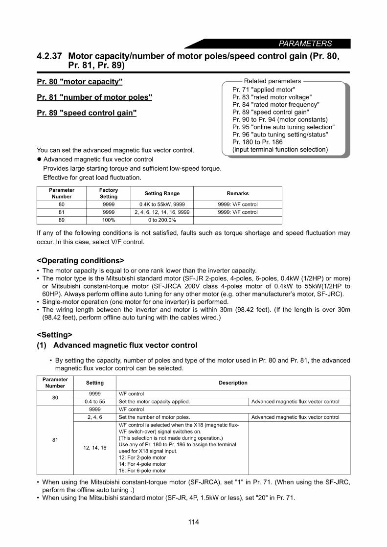
PARAMETERS
4.2.37 Motor capacity/number of motor poles/speed control gain (Pr. 80,Pr. 81, Pr. 89)
Pr. 80 "motor capacity"
Pr. 81 "number of motor poles"
Pr. 89 "speed control gain"
You can set the advanced magnetic flux vector control. Advanced magnetic flux vector control
Provides large starting torque and sufficient low-speed torque.Effective for great load fluctuation.
If any of the following conditions is not satisfied, faults such as torque shortage and speed fluctuation mayoccur. In this case, select V/F control.
<Operating conditions>• The motor capacity is equal to or one rank lower than the inverter capacity.• The motor type is the Mitsubishi standard motor (SF-JR 2-poles, 4-poles, 6-poles, 0.4kW (1/2HP) or more)
or Mitsubishi constant-torque motor (SF-JRCA 200V class 4-poles motor of 0.4kW to 55kW(1/2HP to60HP). Always perform offline auto tuning for any other motor (e.g. other manufacturer’s motor, SF-JRC).
• Single-motor operation (one motor for one inverter) is performed.• The wiring length between the inverter and motor is within 30m (98.42 feet). (If the length is over 30m
(98.42 feet), perform offline auto tuning with the cables wired.)
<Setting>(1) Advanced magnetic flux vector control
• By setting the capacity, number of poles and type of the motor used in Pr. 80 and Pr. 81, the advancedmagnetic flux vector control can be selected.
• When using the Mitsubishi constant-torque motor (SF-JRCA), set "1" in Pr. 71. (When using the SF-JRC,perform the offline auto tuning .)
• When using the Mitsubishi standard motor (SF-JR, 4P, 1.5kW or less), set "20" in Pr. 71.
Parameter Number
FactorySetting Setting Range Remarks
80 9999 0.4K to 55kW, 9999 9999: V/F control81 9999 2, 4, 6, 12, 14, 16, 9999 9999: V/F control89 100% 0 to 200.0%
ParameterNumber Setting Description
809999 V/F control
0.4 to 55 Set the motor capacity applied. Advanced magnetic flux vector control
81
9999 V/F control2, 4, 6 Set the number of motor poles. Advanced magnetic flux vector control
12, 14, 16
V/F control is selected when the X18 (magnetic flux-V/F switch-over) signal switches on.(This selection is not made during operation.)Use any of Pr. 180 to Pr. 186 to assign the terminal used for X18 signal input.12: For 2-pole motor14: For 4-pole motor16: For 6-pole motor
Related parametersPr. 71 "applied motor"Pr. 83 "rated motor voltage"Pr. 84 "rated motor frequency"Pr. 89 "speed control gain"Pr. 90 to Pr. 94 (motor constants)Pr. 95 "online auto tuning selection"Pr. 96 "auto tuning setting/status"Pr. 180 to Pr. 186(input terminal function selection)
114

PARAMETERS
4
For adjustment of motor speed fluctuation due to load variationPr. 89 can be used to adjust motor speed fluctuation when the load varies. (When you have changed theconventional model FR-A200E series for the FR-A500 series, advanced magnetic flux vector control iseffective when motor speed does not match.)
4.2.38 Offline auto tuning function (Pr. 82 to Pr. 84, Pr. 90 to Pr. 94, Pr. 96)
Pr. 82 "motor excitation current"
Pr. 83 "rated motor voltage"
Pr. 84 "rated motor frequency"
Pr. 90 "motor constant (R1)"
Pr. 91 "motor constant (R2)"
Pr. 92 "motor constant (L1)"
Pr. 93 "motor constant (L2)"
Pr. 94 "motor constant (X)"
Pr. 96 "auto-tuning setting/status"
Note: 1. Speed fluctuation is slightly greater than in the V/F control. (Advanced magnetic flux vectorcontrol may not be suitable for machines which attach importance to little speed fluctuation at lowspeed, e.g. grinders, lapping machines.)
2. When the surge voltage suppression filter (FR-ASF-H) is used between the inverter and motor,output torque may reduce.
3. When the terminal functions are changed using Pr. 180 to Pr. 186, the other functions may beaffected. Confirm the functions of the corresponding terminals before making setting.
What is auto tuning?(1) In the magnetic flux vector control system, the motor performance is unleashed to perform operation.(2) Using the auto tuning function improves the operational performance of the motor.(3) There are two ways of auto tuning: offline auto tuning and online auto tuning (Refer to page 123.).(4) There are two ways of offline auto tuning: motor-unrotated method and motor-rotated method.(5) Speed characteristic accuracy
Online>>offline (rotated)>offline (unrotated)>>no tuning
Speed
Load
torq
ue
Related parametersPr. 7 "acceleration time"Pr. 9 "electronic thermal O/L relay"Pr. 71 "applied motor"Pr. 80 "motor capacity"Pr. 81 "number of motor poles"Pr. 95 "online auto tuning selection"Pr. 156 "stall prevention operation
selection"
115
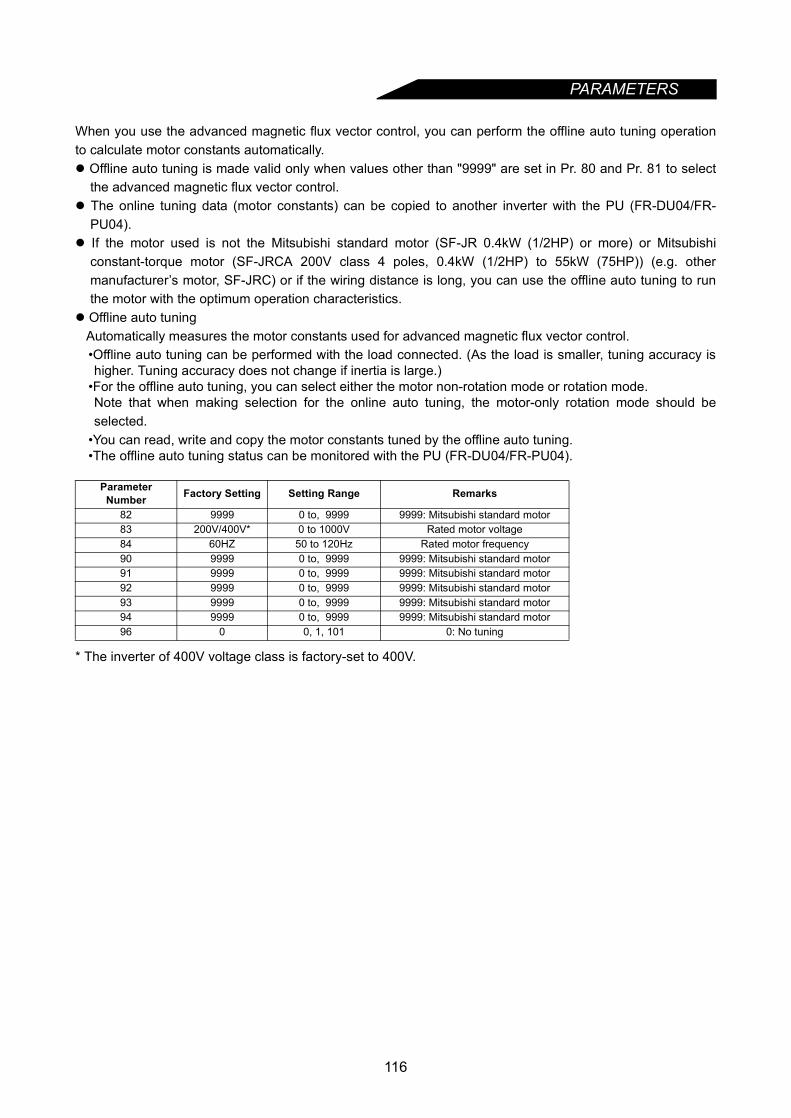
PARAMETERS
When you use the advanced magnetic flux vector control, you can perform the offline auto tuning operationto calculate motor constants automatically. Offline auto tuning is made valid only when values other than "9999" are set in Pr. 80 and Pr. 81 to select
the advanced magnetic flux vector control. The online tuning data (motor constants) can be copied to another inverter with the PU (FR-DU04/FR-
PU04). If the motor used is not the Mitsubishi standard motor (SF-JR 0.4kW (1/2HP) or more) or Mitsubishi
constant-torque motor (SF-JRCA 200V class 4 poles, 0.4kW (1/2HP) to 55kW (75HP)) (e.g. othermanufacturer’s motor, SF-JRC) or if the wiring distance is long, you can use the offline auto tuning to runthe motor with the optimum operation characteristics.
Offline auto tuningAutomatically measures the motor constants used for advanced magnetic flux vector control.•Offline auto tuning can be performed with the load connected. (As the load is smaller, tuning accuracy ishigher. Tuning accuracy does not change if inertia is large.)
•For the offline auto tuning, you can select either the motor non-rotation mode or rotation mode.Note that when making selection for the online auto tuning, the motor-only rotation mode should beselected.
•You can read, write and copy the motor constants tuned by the offline auto tuning.•The offline auto tuning status can be monitored with the PU (FR-DU04/FR-PU04).
* The inverter of 400V voltage class is factory-set to 400V.
Parameter Number Factory Setting Setting Range Remarks
82 9999 0 to, 9999 9999: Mitsubishi standard motor83 200V/400V* 0 to 1000V Rated motor voltage84 60HZ 50 to 120Hz Rated motor frequency90 9999 0 to, 9999 9999: Mitsubishi standard motor91 9999 0 to, 9999 9999: Mitsubishi standard motor92 9999 0 to, 9999 9999: Mitsubishi standard motor93 9999 0 to, 9999 9999: Mitsubishi standard motor94 9999 0 to, 9999 9999: Mitsubishi standard motor96 0 0, 1, 101 0: No tuning
116

PARAMETERS
4
<Operating conditions>• The motor is connected.• The motor capacity is equal to or one rank lower than the inverter capacity. (0.4kW or more)• The maximum frequency is 120Hz.• Special motors such as high-slip motor and high-speed motor cannot be tuned.• When "101" (offline auto tuning with motor running) is set in Pr. 96, note the following:
1) Torque may not be enough during tuning.2) The motor may be run at nearly its rated frequency (Pr. 84 setting) without problem.3) The brake is open.4) No external force is applied to rotate the motor.
• If "1" (tuning without motor running) is set in Pr. 96, the motor may run slightly. Therefore, fix the motorsecurely with a mechanical brake, or before tuning, make sure that there will be no problem in safety if themotor runs.This instruction must be followed especially for vertical lift applications.Note that if the motor runs slightly, tuning performance is unaffected.
<Setting>(1) Parameter setting• Using Pr. 80 and Pr. 81, select the advanced magnetic flux vector control.• Refer to the parameter details list and set the following parameters:
1) Set "1" or "101" in Pr. 96.•For setting of "1" .................................................................Tuning without motor running.
It takes about 25s untiltuning completes.At this time, exciting noise isgenerated.
•For setting of "101" .............................................................Tuning with motor running.It takes about 40s untiltuning completes.The motor rotates at 60Hz.
2) Set the rated motor current (A) in Pr. 9.3) Set the rated motor voltage (V) in Pr. 83.4) Set the rated motor frequency (Hz) in Pr. 84.5) Select the motor using Pr. 71.
•Standard motor ....................................................................................... Pr. 71 = "3"•Constant-torque motor............................................................................ Pr. 71 = "13"•Mitsubishi standard motor SF-JR 4 poles (1.5kW (2HP) or less) . . . . . Pr. 71 = "23"
Note: Offline auto tuning will not be performed properly if it is performed when the reactor or surge voltagesuppression filter (FR-ASF-H) is connected between the inverter and motor.Remove it before starting tuning.
Note: 1. Pr. 83 and Pr. 84 are only displayed when the advanced magnetic flux vector control is selected(Pr. 80, Pr. 81).
2. In these parameters, set the values given on the motor rating plate. When the standard motor hasmore than one rated value, set 200V/60Hz or 400V/60Hz.After tuning is finished, set the Pr. 9 "electronic thermal O/L relay" value to the rated current at theoperating voltage/frequency.
117

PARAMETERS
Parameter details(2) Tuning execution
• For PU operation, press the or key.• For external operation, switch on the run command.
Parameter Number Setting Description
9 0 to 500A Set the rated motor current (A).
71 (Note1)
0 Electronic overcurrent protection thermal characteristics suitable for standard motor
1 Electronic overcurrent protection thermal characteristics suitable for Mitsubishi constant-torque motor
2 Electronic overcurrent protection thermal characteristics suitable for standard motor5-point flexible V/F characteristics
20 Mitsubishi SF-JR4P standard motor (1.5kW (2HP) or less), electronic overcurrent protection thermal characteristics for advanced magnetic flux vector control
3 Standard motor
Select "offline auto tuning setting"13 Constant-torque motor
23 Mitsubishi SF-JR4P standard motor (1.5kW (2HP) or less)
4 Standard motorAuto tuning read or change setting enabled
14 Constant-torque motor
24 Mitsubishi SF-JR4P standard motor (1.5kW (2HP) or less)
5 Standard motor Star connection Direct input of motor constants enabled
15 Constant-torque motor6 Standard motor Delta connection16 Constant-torque motor7 Standard motor Star connection Direct input of
motor constants and offline auto tuning
17 Constant-torque motor8 Standard motor Delta connection18 Constant-torque motor
83 0 to 1000V Set the rated motor voltage (V).84 50 to 120HZ Set the rated motor frequency (Hz).90 0 to, 9999
Tuning data(Values measured by offline auto tuning are set automatically.)
91 0 to, 999992 0 to, 999993 0 to, 9999
94 99990 to 100%
96 (Note2)0 Offline auto tuning is not performed.1 Offline auto tuning is performed without motor running.
101 Offline auto tuning is performed with motor running.
Note: 1. The electronic overcurrent protection characteristics are also selected simultaneously.2. Select "101" to increase tuning accuracy.
Note: 1. When "101" is set in Pr. 96, guard against hazards because the motor rotates.2. To force tuning to end
• Switch on the MRS or RES signal or press the key to end.• Switch off the tuning start command or make a forced stop.
3. During offline auto tuning, the following I/O signals are only valid:• Input signals
STOP, OH, MRS, RT, CS, RES, STF, STR• Output signals
RUN, OL, IPF, FM, AM, A, B, C4. Special caution should be exercised when a sequence has been designed to open the
mechanical brake with the RUN signal.5. When executing offline auto tuning, give the run command after switching on the main circuit
power supply (R, S, T <L1, L2, L3>) of the inverter.
FWD REV
STOPRESET
118
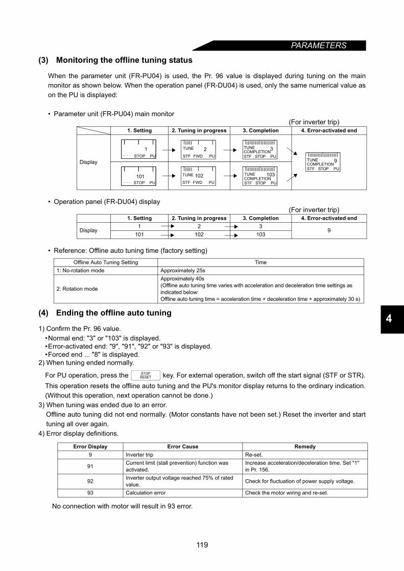
PARAMETERS
4
(3) Monitoring the offline tuning status
When the parameter unit (FR-PU04) is used, the Pr. 96 value is displayed during tuning on the mainmonitor as shown below. When the operation panel (FR-DU04) is used, only the same numerical value ason the PU is displayed:
• Parameter unit (FR-PU04) main monitor(For inverter trip)
• Operation panel (FR-DU04) display(For inverter trip)
• Reference: Offline auto tuning time (factory setting)
(4) Ending the offline auto tuning
1) Confirm the Pr. 96 value.•Normal end: "3" or "103" is displayed.•Error-activated end: "9", "91", "92" or "93" is displayed.•Forced end ... "8" is displayed.
2) When tuning ended normally.
For PU operation, press the key. For external operation, switch off the start signal (STF or STR).This operation resets the offline auto tuning and the PU's monitor display returns to the ordinary indication.(Without this operation, next operation cannot be done.)
3) When tuning was ended due to an error.Offline auto tuning did not end normally. (Motor constants have not been set.) Reset the inverter and starttuning all over again.
4) Error display definitions.
No connection with motor will result in 93 error.
1. Setting 2. Tuning in progress 3. Completion 4. Error-activated end
Display
1. Setting 2. Tuning in progress 3. Completion 4. Error-activated end
Display1 2 3
9101 102 103
Offline Auto Tuning Setting Time1: No-rotation mode Approximately 25s
2: Rotation mode
Approximately 40s(Offline auto tuning time varies with acceleration and deceleration time settings as indicated below:Offline auto tuning time = acceleration time + deceleration time + approximately 30 s)
Error Display Error Cause Remedy9 Inverter trip Re-set.
91 Current limit (stall prevention) function was activated.
Increase acceleration/deceleration time. Set "1" in Pr. 156.
92 Inverter output voltage reached 75% of rated value. Check for fluctuation of power supply voltage.
93 Calculation error Check the motor wiring and re-set.
FWD PU2
STF
TUNE
STOP PU
3STF
TUNECOMPLETION
STOP PU1
STOP PU
9STF
TUNECOMPLETION
STOP PU101
FWD PU102
STF
TUNE
STOP PU
103STF
TUNECOMPLETION
STOPRESET
119

PARAMETERS
5) When tuning was ended focibly.A forced end occurs when tuning is forced to end by pressing the key or turning off the startsignal (STF or STR) during tuning.In this case, offline auto tuning was not brought to a normal end. (The motor constants are not yet set.)Reset the inverter and restart tuning.
<Setting the motor constants as desired>The motor constants (Pr. 90 to Pr. 94) may be set as desired in either of two ways; the data measuredin the offline auto tuning is read and utilized or changed, or the motor constants are set without theoffline auto tuning data being used.
To utilize or change the offline auto tuning data<Operating procedure>1. Set any of the following values in Pr. 71:
• Standard motor ................................................................................. Pr. 71 = "4"• Constant-torque motor...................................................................... Pr. 71 = "14"• Mitsubishi standard motor SF-JR 4 poles (1.5kW (2HP) or less) Pr. 71 = "24"
2. Set "801" in Pr. 77.(Only when the Pr. 80 and Pr. 81 settings are other than "9999", the parameter values of the motorexciting current (Pr. 82) and motor constants (Pr. 90 to Pr. 94) can be displayed. Though theparameter values of other than Pr. 82 and Pr. 90 to Pr. 94 can be displayed, they are parameters formanufacturer setting and shall not be changed.)
3. In the parameter setting mode, read the following parameters and set desired values. (Note 1)
4. Return the Pr. 77 setting to the original value.
Note: 1. The motor constants measured once in the offline auto tuning are stored as parameters and theirdata is held until the offline auto tuning is performed again.
2. An instantaneous power failure occurring during tuning will result in a tuning error. After power isrestored, the inverter goes into the ordinary operation mode. Therefore, when STF (STR) is on,the motor runs in forward (reverse) rotation.
3. When "8888" is set in Pr. 11, the tuning is forced to end and the DC injection brake is startedupon input of the MRS signal.
4. Any alarm occurring during tuning is handled as in the ordinary mode.Note that if an error retry has been set, retry is ignored.
5. The set frequency monitor displayed during the offline auto tuning is 0Hz.
CAUTION
Note that the motor may start running suddenly. When the offline auto tuning is used in vertical lift application, e.g. a lifter, it may drop due to insufficient torque.
ParameterNumber Name Setting Range SettingIncre
mentsFactorySetting
82 Motor exciting current 0 to ****, 9999 1 999990 Motor constant R1 0 to ****, 9999 1 999991 Motor constant R2 0 to ****, 9999 1 999992 Motor constant L1 0 to ****, 9999 1 999993 Motor constant L2 0 to ****, 9999 1 999994 Motor constant X 0 to ****, 9999 1 9999
STOPRESET
120
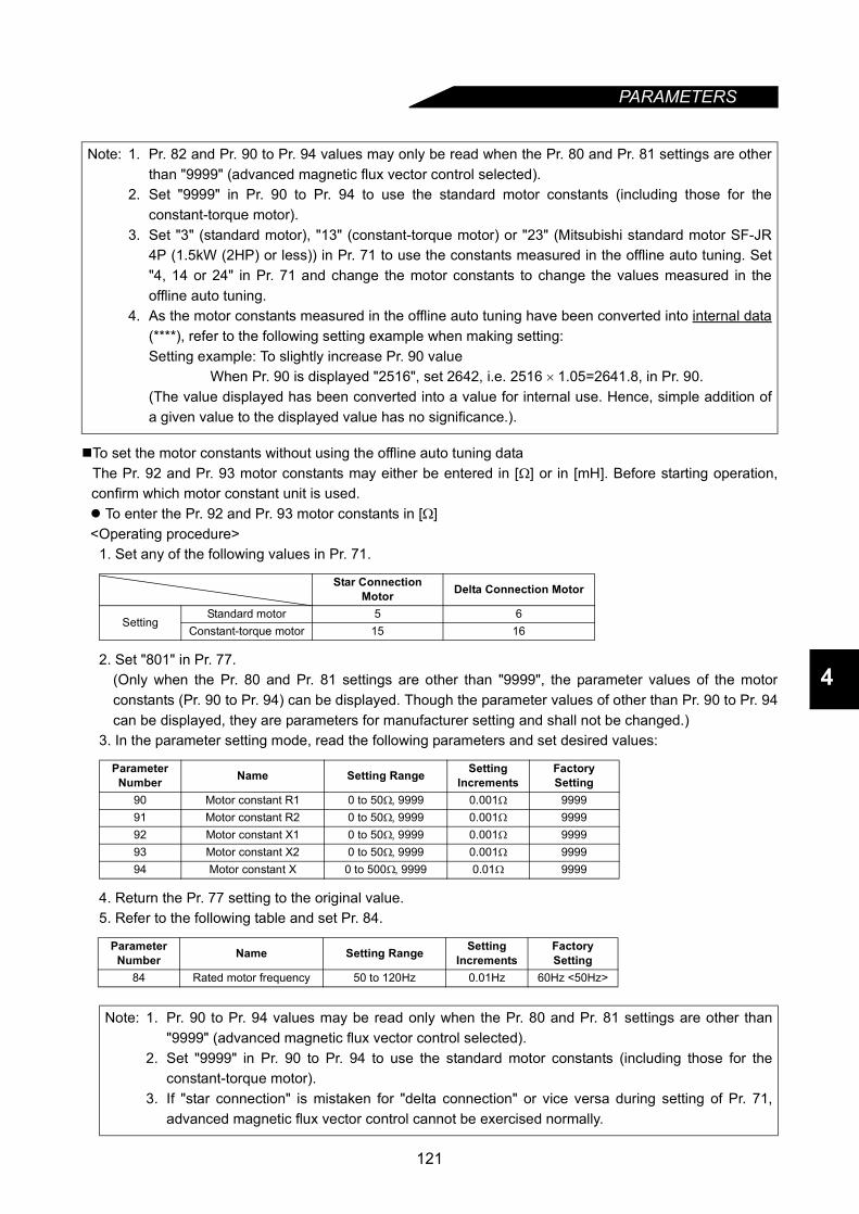
PARAMETERS
4
To set the motor constants without using the offline auto tuning dataThe Pr. 92 and Pr. 93 motor constants may either be entered in [Ω] or in [mH]. Before starting operation,confirm which motor constant unit is used. To enter the Pr. 92 and Pr. 93 motor constants in [Ω]<Operating procedure>
1. Set any of the following values in Pr. 71.
2. Set "801" in Pr. 77. (Only when the Pr. 80 and Pr. 81 settings are other than "9999", the parameter values of the motorconstants (Pr. 90 to Pr. 94) can be displayed. Though the parameter values of other than Pr. 90 to Pr. 94can be displayed, they are parameters for manufacturer setting and shall not be changed.)
3. In the parameter setting mode, read the following parameters and set desired values:
4. Return the Pr. 77 setting to the original value.5. Refer to the following table and set Pr. 84.
Note: 1. Pr. 82 and Pr. 90 to Pr. 94 values may only be read when the Pr. 80 and Pr. 81 settings are otherthan "9999" (advanced magnetic flux vector control selected).
2. Set "9999" in Pr. 90 to Pr. 94 to use the standard motor constants (including those for theconstant-torque motor).
3. Set "3" (standard motor), "13" (constant-torque motor) or "23" (Mitsubishi standard motor SF-JR4P (1.5kW (2HP) or less)) in Pr. 71 to use the constants measured in the offline auto tuning. Set"4, 14 or 24" in Pr. 71 and change the motor constants to change the values measured in theoffline auto tuning.
4. As the motor constants measured in the offline auto tuning have been converted into internal data(****), refer to the following setting example when making setting:Setting example: To slightly increase Pr. 90 value
When Pr. 90 is displayed "2516", set 2642, i.e. 2516 × 1.05=2641.8, in Pr. 90.(The value displayed has been converted into a value for internal use. Hence, simple addition ofa given value to the displayed value has no significance.).
Star Connection Motor Delta Connection Motor
SettingStandard motor 5 6
Constant-torque motor 15 16
Parameter Number Name Setting Range Setting
IncrementsFactory Setting
90 Motor constant R1 0 to 50Ω, 9999 0.001Ω 999991 Motor constant R2 0 to 50Ω, 9999 0.001Ω 999992 Motor constant X1 0 to 50Ω, 9999 0.001Ω 999993 Motor constant X2 0 to 50Ω, 9999 0.001Ω 999994 Motor constant X 0 to 500Ω, 9999 0.01Ω 9999
Parameter Number Name Setting Range Setting
IncrementsFactory Setting
84 Rated motor frequency 50 to 120Hz 0.01Hz 60Hz <50Hz>
Note: 1. Pr. 90 to Pr. 94 values may be read only when the Pr. 80 and Pr. 81 settings are other than"9999" (advanced magnetic flux vector control selected).
2. Set "9999" in Pr. 90 to Pr. 94 to use the standard motor constants (including those for theconstant-torque motor).
3. If "star connection" is mistaken for "delta connection" or vice versa during setting of Pr. 71,advanced magnetic flux vector control cannot be exercised normally.
121
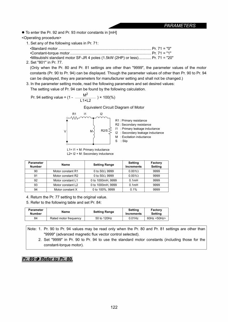
PARAMETERS
To enter the Pr. 92 and Pr. 93 motor constants in [mH]<Operating procedure>1. Set any of the following values in Pr. 71:•Standard motor ....................................................................................... Pr. 71 = "0"•Constant-torque motor ............................................................................ Pr. 71 = "1"•Mitsubishi standard motor SF-JR 4 poles (1.5kW (2HP) or less)............ Pr. 71 = "20"
2. Set "801" in Pr. 77. (Only when the Pr. 80 and Pr. 81 settings are other than "9999", the parameter values of the motorconstants (Pr. 90 to Pr. 94) can be displayed. Though the parameter values of other than Pr. 90 to Pr. 94can be displayed, they are parameters for manufacturer setting and shall not be changed.)
3. In the parameter setting mode, read the following parameters and set desired values:The setting value of Pr. 94 can be found by the following calculation.
Equivalent Circuit Diagram of Motor
4. Return the Pr. 77 setting to the original value.5. Refer to the following table and set Pr. 84:
Pr. 94 setting value = (1 - M2) × 100(%)
L1×L2
Parameter Number Name Setting Range Setting
IncrementsFactory Setting
90 Motor constant R1 0 to 50Ω, 9999 0.001Ω 999991 Motor constant R2 0 to 50Ω, 9999 0.001Ω 999992 Motor constant L1 0 to 1000mH, 9999 0.1mH 999993 Motor constant L2 0 to 1000mH, 9999 0.1mH 999994 Motor constant X 0 to 100%, 9999 0.1% 9999
Parameter Number Name Setting Range Setting
IncrementsFactory Setting
84 Rated motor frequency 50 to 120Hz 0.01Hz 60Hz <50Hz>
Note: 1. Pr. 90 to Pr. 94 values may be read only when the Pr. 80 and Pr. 81 settings are other than"9999" (advanced magnetic flux vector control selected).
2. Set "9999" in Pr. 90 to Pr. 94 to use the standard motor constants (including those for theconstant-torque motor).
L1= I1 + M: Primary inductanceL2= I2 + M: Secondary inductance
MV R2/S
R1 : Primary resistanceR2 : Secondary resistanceI1 : Primary leakage inductanceI2 : Secondary leakage inductanceM : Excitation inductanceS : Slip
R1 I1 I2
Pr. 89 Refer to Pr. 80.
122
PARAMETERS
4
4.2.39 Online auto tuning selection (Pr. 95)
Pr. 95 "online auto tuning selection"
By online auto tuning, the motor conditions are tuned rapidly at the start. This enables precise operationunaffected by motor temperatures and steady high-torque operation down to super-low speed. After settingthe Pr. 80 and Pr. 81 values, select online auto tuning with Pr. 95. Online auto tuning
Use this function when steady high-torque operation is required for low-speed operation under advancedmagnetic flux vector control.
• Before starting the online auto tuning, perform the offline auto tuning. Data must be calculated.
<Operating conditions>• Data required for online auto tuning is calculated in offline auto tuning. Before starting the operation of
this function, always execute the offline auto tuning once more. The offline auto tuning is also requiredfor use of the Mitsubishi standard motor (SF-JR) or constant-torque motor (SF-JRCA).
• Offline auto tuning should be carried out with "101" (motor running) set in Pr. 96 and with the motordisconnected from the load. (The motor may be connected with inertia load.)
<Operating procedure>1) Read the Pr. 96 value and make sure that its setting is "3 or 103" (offline auto tuning complete).2) Set "1" in Pr. 95 to select the online auto tuning.3) Before starting operation, make sure that the following parameter values have been set:
Parameter Number
FactorySetting Setting Range Remarks
95 0 0.1 1: Online auto tuning
Parameter Number Description
9 (Used as either the rated motor current or electronic overcurrent protection parameter)71 Applied motor80 Motor capacity (down to one rank lower, between 0.4kW and 55kW)81 Number of motor poles
Related parametersPr. 71 "applied motor"Pr. 80 "motor capacity"Pr. 81 "number of motor poles"Pr. 83 "rated motor voltage"Pr. 84 "rated motor frequency"Pr. 89 "speed control gain"Pr. 90 to Pr. 94 (motor constants)Pr. 96 "auto tuning setting/status"
123
PARAMETERS
4) Give the run command in the PU or external operation mode.Note: 1. If any of the inverter starting conditions are not satisfied, e.g. when MRS is input, if the setfrequency is lower than the starting frequency (Pr. 13) value, or during an inverter error, theonline auto tuning is not activated.
2. For a restart during deceleration or DC injection brake operation, the online auto tuning is notactivated.
3. The online auto tuning is invalid for programmed operation or jog operation.4. When automatic restart after instantaneous power failure is selected, it overrides the online
auto tuning.5. For use in vertical lift application, examine the use of a brake sequence for brake opening
timing at the start. Though the tuning ends in about a maximum of 500ms after a start, enoughtorque is not provided during that period. Therefore, note that the load may drop with gravity.
6. Zero current detection and output current detection are also valid during the online autotuning.
7. The RUN signal is not output during the online auto tuning. The RUN signal switches on at astart.
8. When programmed operation is selected (Pr. 79 = 5), the online auto tuning is invalid and isnot executed.
9. If the period between inverter stop and restart is within 4s, the online auto tuning is executedbut operation will not reflect the tuning results.
Pr. 96 Refer to Pr. 82.
124
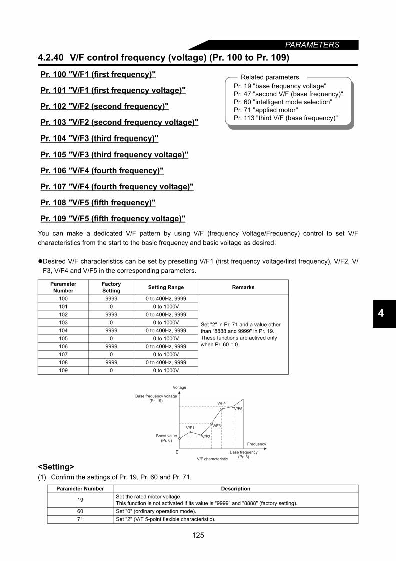
PARAMETERS
4
4.2.40 V/F control frequency (voltage) (Pr. 100 to Pr. 109)
You can make a dedicated V/F pattern by using V/F (frequency Voltage/Frequency) control to set V/Fcharacteristics from the start to the basic frequency and basic voltage as desired.
Desired V/F characteristics can be set by presetting V/F1 (first frequency voltage/first frequency), V/F2, V/F3, V/F4 and V/F5 in the corresponding parameters.
<Setting>(1) Confirm the settings of Pr. 19, Pr. 60 and Pr. 71.
Pr. 100 "V/F1 (first frequency)"
Pr. 101 "V/F1 (first frequency voltage)"
Pr. 102 "V/F2 (second frequency)"
Pr. 103 "V/F2 (second frequency voltage)"
Pr. 104 "V/F3 (third frequency)"
Pr. 105 "V/F3 (third frequency voltage)"
Pr. 106 "V/F4 (fourth frequency)"
Pr. 107 "V/F4 (fourth frequency voltage)"
Pr. 108 "V/F5 (fifth frequency)"
Pr. 109 "V/F5 (fifth frequency voltage)"
Parameter Number
FactorySetting Setting Range Remarks
100 9999 0 to 400Hz, 9999
Set "2" in Pr. 71 and a value other than "8888 and 9999" in Pr. 19. These functions are actived only when Pr. 60 = 0.
101 0 0 to 1000V102 9999 0 to 400Hz, 9999103 0 0 to 1000V104 9999 0 to 400Hz, 9999105 0 0 to 1000V106 9999 0 to 400Hz, 9999107 0 0 to 1000V108 9999 0 to 400Hz, 9999109 0 0 to 1000V
Parameter Number Description
19 Set the rated motor voltage.This function is not activated if its value is "9999" and "8888" (factory setting).
60 Set "0" (ordinary operation mode).71 Set "2" (V/F 5-point flexible characteristic).
Related parametersPr. 19 "base frequency voltage"Pr. 47 "second V/F (base frequency)"Pr. 60 "intelligent mode selection"Pr. 71 "applied motor"Pr. 113 "third V/F (base frequency)"
0
V/F5
V/F4
V/F3
V/F2
V/F1
Voltage
Base frequency voltage(Pr. 19)
Boost value(Pr. 0)
V/F characteristic
Base frequency(Pr. 3)
Frequency
125
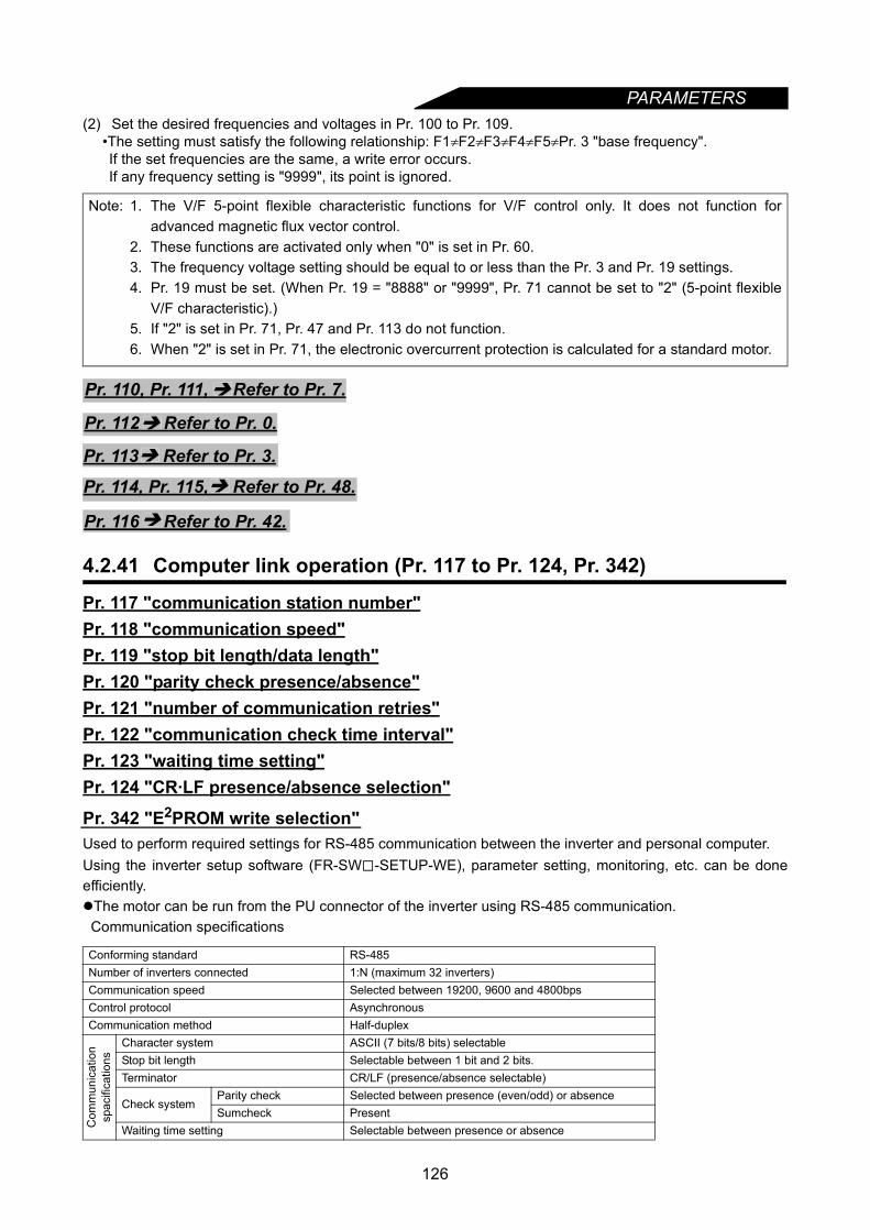
PARAMETERS
(2) Set the desired frequencies and voltages in Pr. 100 to Pr. 109.•The setting must satisfy the following relationship: F1≠F2≠F3≠F4≠F5≠Pr. 3 "base frequency".If the set frequencies are the same, a write error occurs.If any frequency setting is "9999", its point is ignored.
4.2.41 Computer link operation (Pr. 117 to Pr. 124, Pr. 342)
Pr. 117 "communication station number"Pr. 118 "communication speed"Pr. 119 "stop bit length/data length"Pr. 120 "parity check presence/absence"Pr. 121 "number of communication retries"Pr. 122 "communication check time interval"Pr. 123 "waiting time setting"Pr. 124 "CR·LF presence/absence selection"
Pr. 342 "E2PROM write selection"Used to perform required settings for RS-485 communication between the inverter and personal computer.Using the inverter setup software (FR-SW -SETUP-WE), parameter setting, monitoring, etc. can be doneefficiently.The motor can be run from the PU connector of the inverter using RS-485 communication.Communication specifications
Note: 1. The V/F 5-point flexible characteristic functions for V/F control only. It does not function foradvanced magnetic flux vector control.
2. These functions are activated only when "0" is set in Pr. 60.3. The frequency voltage setting should be equal to or less than the Pr. 3 and Pr. 19 settings.4. Pr. 19 must be set. (When Pr. 19 = "8888" or "9999", Pr. 71 cannot be set to "2" (5-point flexible
V/F characteristic).)5. If "2" is set in Pr. 71, Pr. 47 and Pr. 113 do not function.6. When "2" is set in Pr. 71, the electronic overcurrent protection is calculated for a standard motor.
Conforming standard RS-485Number of inverters connected 1:N (maximum 32 inverters)Communication speed Selected between 19200, 9600 and 4800bpsControl protocol AsynchronousCommunication method Half-duplex
Com
mun
icat
ion
spac
ifica
tions
Character system ASCII (7 bits/8 bits) selectableStop bit length Selectable between 1 bit and 2 bits.Terminator CR/LF (presence/absence selectable)
Check systemParity check Selected between presence (even/odd) or absenceSumcheck Present
Waiting time setting Selectable between presence or absence
Pr. 110, Pr. 111, Refer to Pr. 7.
Pr. 112 Refer to Pr. 0.
Pr. 113 Refer to Pr. 3.
Pr. 114, Pr. 115, Refer to Pr. 48.
Pr. 116 Refer to Pr. 42.
126

PARAMETERS
4
For the instruction codes of the parameters, refer to the instruction code list in the appendices.
* When making communication, set any value other than 0 in Pr. 122 "communication check time interval".<Setting>To make communication between the personal computer and inverter, the communication specificationsmust be set to the inverter initially. If initial setting is not made or there is a setting fault, data transfer cannotbe made.Note: After making the initial setting of the parameters, always reset the inverter. After you have changed the
communication-related parameters, communication cannot be made until the inverter is reset.
* When you have set write to RAM, powering off the inverter clears the parameter values that have beenchanged. Therefore the parameter values available when power is switched on again are those storedpreviously in E2PROM.When changing parameter values frequently, set "1" in Pr. 342 to choose write to RAM.The Pr. 342 " E2PROM write selection" setting is also valid when the communication option is fitted.Performing frequent parameter write with E2PROM write set will shorten the life of the E2PROM.
REMARKSFor computer link operation, set the value "8888" as 65520 (HFFF0) and the value "9999" as 65535(HFFFF).
Parameter Number Factory Setting Setting Range117 0 0 to 31118 192 48, 96, 192
119 1Data length 8 0, 1Data length 7 10, 11
120 2 0, 1, 2121 1 0 to 10, 9999122* 0<9999> 0, 0.1 to 999.8s, 9999123 9999 0 to 150ms, 9999124 1 0, 1, 2342 0 0, 1
Parameter Number Description Setting Description
117 Communication station number 0 to 31
Station number specified for communication from the PU connector. Set the inverter station numbers when two or more inverters are connected to one personal computer.
118 Communication speed
48 4800 bps96 9600 bps
192 19200 bps
119 Stop bit length/data length
8 bits0 Stop bit length 1 bit1 Stop bit length 2 bits
7 bits10 Stop bit length 1 bit11 Stop bit length 2 bits
120Parity check presence/absence
0 Absent1 Odd parity present2 Even parity present
121Number of communication retries
0 to 10Set the permissible number of retries at occurrence of data receive error. If the number of consecutive errors exceeds the permissible value, the inverter will come to an alarm stop.
9999(65535)If a communication error occurs, the inverter will not come to an alarm stop. At this time, the inverter can be coasted to a stop by MRS or RES input. During a communication error (H0 to H5), the minor fault signal (LF) is switched on. Allocate the used terminal with any of Pr. 190 to Pr. 195 (output terminal function selection).
122Communication check time interval
0 No communication0.1 to 999.8 Set the communication check time [s] interval.
9999 If a no-communication state persists for longer than the permissible time, the inverter will come to an alarm stop.
123 Waiting time setting
0 to 150ms Set the waiting time between data transmission to the inverter and response.9999 Set with communication data.
124CR • LF presence/absence selection
0 Without CR • LF1 With CR • Without LF2 With CR • LF
342* E2PROM write selection
0 When parameter write is performed from the computer, parameters are written to E2PROM.
1 When parameter write is performed from the computer, parameters are written to RAM.
127

PARAMETERS
<Computer programming>(1) Communication protocolData communication between the computer and inverter is performed using the following procedure:
*1. If a data error is detected and a retry must be made, execute retry operation from the user program. The inverter comes to an alarm stop if the number of consecutive retries exceeds the parameter setting.
*2. On receipt of a data error occurrence, the inverter returns "reply data 3)" to the computer again. Theinverter comes to an alarm stop if the number of consecutive data errors reaches or exceeds theparameter setting.
(2) Communication operation presence/absence and data format typesCommunication operation presence/absence and data format types are as follows:
* In the communication request data given from the computer to the inverter, 10ms or more is also requiredafter "no data error (ACK)". (Refer to page 130.)
(3) Data formatHexadecimal data is used. Data is automatically transferred in ASCII between the computer and inverter.(1) Data format types
1) Communication request data from computer to inverter
No. Operation Run Command
Running Frequency
Parameter Write
Inverter Reset Monitoring Parameter
Read
1) Communication request is sent to the inverter in accordance with the user program. A’ A A A B B
2) Inverter data processing time Present Present Present Absent Present Present
3)
Reply data from the inverter(Data 1) is checked for error)
No error* (Request accepted) C C C Absent E
E’ E
With error (request rejected) D D D Absent F F
4) Computer processing delay time Absent Absent Absent Absent Absent Absent
5)
Answer from computer in response to reply data 3)(Data 3) is checked for error)
No error* (No inverter processing)
Absent Absent Absent Absent G G
With error.Inverter outputs 3) again.
Absent Absent Absent Absent H H
*1
*2
Computer
Inverter
↓ (Data flow)
Computer
↓ (Data flow)
Inverter
Data read
Data write
Time1)
2) 3)
4) 5)
*1ENQ *4
1 2 3 4 5 6 7 8 9 10 11 12 13
*1ENQ *4
1 2 3 4 5 6 7 8 9 10 11
*1ENQ *4
1 2 3 4 5 6 7 8 9
[Data format]
Format A
[Data read]
Format A'
Format B
*2 Inverterstationnumber
Instructioncode
*3Waiting
time
Data
Sumcheck
Instructioncode
Instructioncode
*3Waiting
time
*3Waiting
time
Data
Sumcheck
Sumcheck
←Number of characters
←Number of characters
←Number of characters
*2 Inverterstationnumber
*2 Inverterstationnumber
128
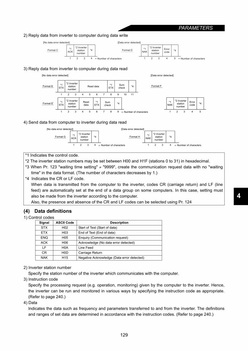
PARAMETERS
4
2) Reply data from inverter to computer during data write
3) Reply data from inverter to computer during data read
4) Send data from computer to inverter during data read
(4) Data definitions1) Control codes
2) Inverter station numberSpecify the station number of the inverter which communicates with the computer.
3) Instruction codeSpecify the processing request (e.g. operation, monitoring) given by the computer to the inverter. Hence,the inverter can be run and monitored in various ways by specifying the instruction code as appropriate.(Refer to page 240.)
4) DataIndicates the data such as frequency and parameters transferred to and from the inverter. The definitionsand ranges of set data are determined in accordance with the instruction codes. (Refer to page 240.)
*1 Indicates the control code.*2 The inverter station numbers may be set between H00 and H1F (stations 0 to 31) in hexadecimal.*3 When Pr. 123 "waiting time setting" ≠ "9999", create the communication request data with no "waiting
time" in the data format. (The number of characters decreases by 1.)*4 Indicates the CR or LF code.
When data is transmitted from the computer to the inverter, codes CR (carriage return) and LF (linefeed) are automatically set at the end of a data group on some computers. In this case, setting mustalso be made from the inverter according to the computer.Also, the presence and absence of the CR and LF codes can be selected using Pr. 124
Signal ASCII Code DescriptionSTX H02 Start of Text (Start of data)ETX H03 End of Text (End of data)ENQ H05 Enquiry (Communication request)ACK H06 Acknowledge (No data error detected)LF H0A Line FeedCR H0D Carriage Return
NAK H15 Negative Acknowledge (Data error detected)
*1ACK
*4
1 2 3 4
*1NAK
1 2 3 4
*4
5
[No data error detected] [Data error detected]
Format C Format D*2 Inverter
stationnumber
Errorcode
←Number of characters←Number of characters
*2 Inverterstationnumber
1 2 3 4 5
1 2 3 4 5 6 7 8 9 10 11
[No data error detected]
1 2 3 4 5 6 7 8 9
*1STXFormat E
Readdata
Sumcheck
←Number of characters
Format E'
*1ETX *4Read data
Sumcheck *4*1
ETX*1
STX
[Data error detected]
Format F
*1NAK
Errorcode *4
*2 Inverterstationnumber
*2 Inverterstationnumber
*2 Inverterstationnumber
1 2 3 4 1 2 3 4
[No data error detected]
*1ACKFormat G
←Number of characters
Format H*4 *1NAK
[Data error detected]
*4*2 Inverter
stationnumber
←Number of characters
*2 Inverterstationnumber
129
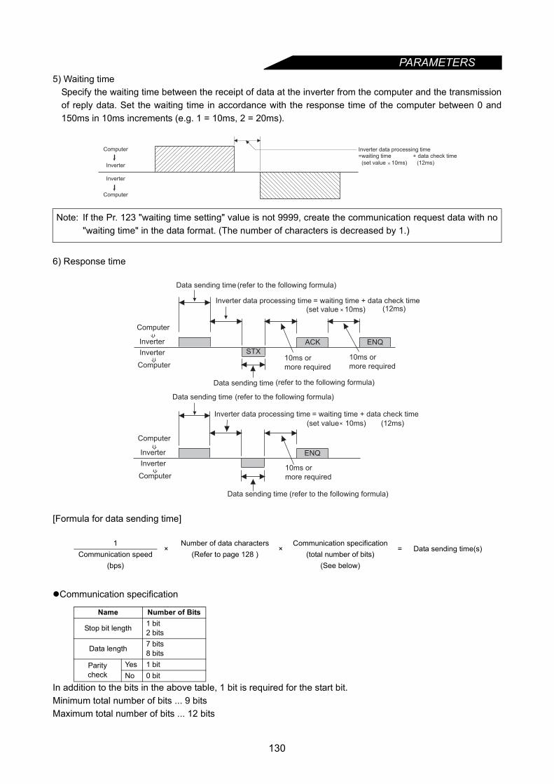
PARAMETERS
5) Waiting timeSpecify the waiting time between the receipt of data at the inverter from the computer and the transmissionof reply data. Set the waiting time in accordance with the response time of the computer between 0 and150ms in 10ms increments (e.g. 1 = 10ms, 2 = 20ms).
6) Response time
[Formula for data sending time]
Communication specification
In addition to the bits in the above table, 1 bit is required for the start bit.Minimum total number of bits ... 9 bitsMaximum total number of bits ... 12 bits
Note: If the Pr. 123 "waiting time setting" value is not 9999, create the communication request data with no"waiting time" in the data format. (The number of characters is decreased by 1.)
1×
Number of data characters×
Communication specification= Data sending time(s)
Communication speed (Refer to page 128 ) (total number of bits)(bps) (See below)
Name Number of Bits
Stop bit length 1 bit2 bits
Data length 7 bits8 bits
Parity check
Yes 1 bitNo 0 bit
Computer
Inverter
Inverter
Computer
Inverter data processing time=waiting time + data check time
(set value 10ms) (12ms)
(set value 10ms)
(set value 10ms)
Inverter
Computer
(refer to the following formula)
Inverter data processing time = waiting time + data check time(12ms)
10ms or
more required10ms or
more required
(refer to the following formula)
STX
ACK ENQ
(refer to the following formula)
Inverter data processing time = waiting time + data check time
(12ms)
10ms or
more required
Data sending time (refer to the following formula)
ENQ
Data sending time
Data sending time
Data sending time
Computer
Inverter
Inverter
Computer
Computer
Inverter
130

PARAMETERS
4
7) Break in the cable detection• If disconnection (communication stop) is detected between the inverter and computer as a result of
disconnection check, a communication error (E.PUE) occurs and the inverter output is shut off.• Disconnection check is made when the setting is any of "0.1s" to "999.8s".To make disconnection check, it
is necessary to send data (control code refer to page 129) from the computer within the communicationcheck time interval. (The send data has nothing to do with the station number)
• Communication check is started at the first communication in the operation mode having the operationsource (PU operation mode in the default setting).
• When the setting is "9999", communication check (disconnection detection) is not made.• When the setting is "0", communication from the PU connector cannot be performed.
8) Sum check codeThe sum check code is 2-digit ASCII (hexadecimal) representing the lower 1 byte (8 bits) of the sum(binary) derived from the checked ASCII data.
9) Error codeIf any error is found in the data received by the inverter, its definition is sent back to the computer togetherwith the NAK code. (Refer to page 135.)
Computer
Operation Mode
Example: Pr. 122 = "0.1 to 999.8s"
External PU
Check start
Alarm(E.PUE)
InverterInverter
Computer
Pr.122E
NQ
Communication
check counter
10 1 E 1 0 7 A D F 4
H05 H30 H31 H31H45 H31 H30 H37 H41 H44 H46 H34
(Example1)
Computer→Inverter
ASCII code→
Stationnumber
Instructioncode Data Sum check
code
←Binary code
Sum
↓
30 + 31 + 45 + 31 + 31 + 30 + 37 + 41 + 44
=1F4
HH H H H H H H H
H
0 1 1 7 0 3 0H02 H30 H31 H37H31 H37 H30 H03 H33 H30
7
(Example2)
Inverter→Computer
ASCII code→
←Binary code
Sum checkcode
STX Stationnumber Read data ETX
Sum
↓
30 + 31 + 31 + 37 + 37 + 30
=130
HH H H H H
H
ENQ
*When Pr. 123 "waiting time setting" ≠ 9999, create the communication request data with no "waiting time" in the data format. (The number of characters is decreased by 1.)
*Wai
ting
time
131
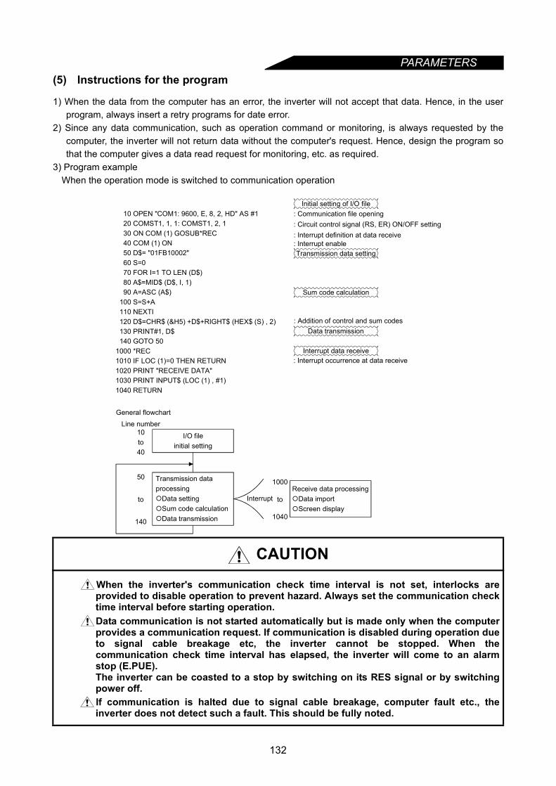
PARAMETERS
(5) Instructions for the program1) When the data from the computer has an error, the inverter will not accept that data. Hence, in the userprogram, always insert a retry programs for date error.
2) Since any data communication, such as operation command or monitoring, is always requested by thecomputer, the inverter will not return data without the computer's request. Hence, design the program sothat the computer gives a data read request for monitoring, etc. as required.
3) Program exampleWhen the operation mode is switched to communication operation
CAUTION
When the inverter's communication check time interval is not set, interlocks areprovided to disable operation to prevent hazard. Always set the communication checktime interval before starting operation.Data communication is not started automatically but is made only when the computerprovides a communication request. If communication is disabled during operation dueto signal cable breakage etc, the inverter cannot be stopped. When thecommunication check time interval has elapsed, the inverter will come to an alarmstop (E.PUE).The inverter can be coasted to a stop by switching on its RES signal or by switchingpower off.If communication is halted due to signal cable breakage, computer fault etc., theinverter does not detect such a fault. This should be fully noted.
I/O file initial setting
10 OPEN "COM1: 9600, E, 8, 2, HD" AS #1 20 COMST1, 1, 1: COMST1, 2, 1 30 ON COM (1) GOSUB*REC 40 COM (1) ON 50 D$= "01FB10002" 60 S=0 70 FOR I=1 TO LEN (D$) 80 A$=MID$ (D$, I, 1) 90 A=ASC (A$) 100 S=S+A 110 NEXTI 120 D$=CHR$ (&H5) +D$+RIGHT$ (HEX$ (S) , 2) 130 PRINT#1, D$ 140 GOTO 501000 *REC1010 IF LOC (1)=0 THEN RETURN1020 PRINT "RECEIVE DATA"1030 PRINT INPUT$ (LOC (1) , #1)1040 RETURN
Initial setting of I/O file: Communication file opening: Circuit control signal (RS, ER) ON/OFF setting: Interrupt definition at data receive: Interrupt enableTransmission data setting
Sum code calculation
: Addition of control and sum codesData transmission
Interrupt data receive: Interrupt occurrence at data receive
Receive data processingData importScreen display
General flowchartLine number
10
40
50
140
Transmission data processingData settingSum code calculationData transmission
Interrupt
1000
1040
to
to to
132

PARAMETERS
4
<Setting items and set data>After completion of parameter setting, set the instruction codes and data and start communication from thecomputer to allow various types of operation control and monitoring.
No. Item Instruction Code Description Number of
Data Digits
1 Operation mode
Read H7BH0000: Communication option operationH0001: External operationH0002: Communication operation (PU connector)
4 digits
Write HFBH0000: Communication option operationH0001: External operationH0002: Communication operation (PU connector)
2
Mon
itorin
g
Output frequency [speed] H6F
H0000 to HFFFF: Output frequency (hexadecimal) in 0.01Hz increments[Speed (hexadecimal) in r/min increments if Pr. 37 = 1 to 9998 or Pr. 144 = 2 to 10, 102 to 110.]
4 digits
Output current H70 H0000 to HFFFF: Output current (hexadecimal) in 0.01A increments 4 digitsOutput voltage H71 H0000 to HFFFF: Output voltage (hexadecimal) in 0.1V increments 4 digitsSpecial monitor H72 H0000 to HFFFF: Monitored data selected by instruction code HF3 4 digits
Special monitor selection No.
Read H73
H01 to H0E Monitor selection data
2 digits
Write HF3
Alarm definition H74 to H77
H0000 to HFFFF: Two most recent alarm definitions
Alarm data
4 digits
Data Description Incre-ments
H01 Output frequency 0.01HzH02 Output current 0.01AH03 Output voltage 0.1VH05 Frequency setting 0.01HzH06 Running speed 1 r/minH07 Motor torque 0.1%
H08 Converter output voltage 0.1V
H09 Regenerative brake 0.1%
H0A
Electronic overcurrent protection load factor
0.1%
H0B Output current peak value 0.01A
H0C Converter output voltage peak value 0.1V
H0D Input power 0.01kWH0E Output power 0.01kW
Data Description Incre-ments
Read data: [Example] H30A0
Most recent alarm(HA0)
b15 b8b7 b0
0 0 1 1 0 0 0 0 0 0 0 0 00 1 1
(Previous alarm ........ THT)(Most recent alarm ..... OPT)
Previous alarm(H30)
Data Description
H00 No alarmH10 0C1H11 0C2H12 0C3H20 0V1H21 0V2H22 0V3H30 THTH31 THMH40 FINH50 IPFH51 UVTH60 OLTH70 BE
H80 GFH81 LFH90 OHTHA0 OPTHA1 OP1HA2 OP2HA3 OP3HB0 PEHB1 PUEHB2 RETHC1 CTEHC2 P24HD1 OSDHD2 ECT
Data Description
HD5 MB1HD6 MB2HD7 MB3HD8 MB4HD9 MB5HDA MB6HDB MB7HF1 E. 1HF2 E. 2HF3 E. 3HF6 E. 6HF7 E. 7
Data Description
133

PARAMETERS
3 Run command HFA 2 digits
4 Inverter status monitor H7A
*The output data depends on the Pr. 190 to Pr. 195 settings.
2 digits
5
Set frequency read (E2PROM)
H6EReads the set frequency (RAM or E2PROM).H0000 to H9C40: 0.01Hz increments (hexadecimal)
4 digitsSet frequency read (RAM) H6D
Set frequency write (E2PROM)
HEE H0000 to H9C40: 0.01Hz increments (hexadecimal)(0 to 400.00 Hz)To change the set frequency consecutively, write data to the inverter RAM. (Instruction code: HED)
4 digitsSet frequency write (RAM) HED
6 Inverter reset HFDH9696: Resets the inverter.As the inverter is reset at start of communication by the computer, the inverter cannot send reply data back to the computer.
4 digits
7 Alarm definition batch clear HF4 H9696: Batch clear of alarm history 4 digits
8 All parameter clear HFC
All parameters return to the factory settings.Any of four different clear operations is performed according to the data.
When all parameter clear is executed for H9696 or H9966, communication-related parameter settings also return to the factory settings. When resuming operation, set the parameters again.*Pr. 75 value is not cleared
4 digits
9 User clear HFC
H9669: User clear is made.
*Pr. 75, Pr. 180 to Pr. 186 and Pr. 190 to Pr. 195 values are not cleared.
4 digits
10 Parameter write H80 to HE3 Refer to the data list (Appendix 1) and write and/or read parameter values as required. 4 digits
11 Parameter read H00 to H63
12
Link parameter expansion setting
Read H7F Changes the parameter details by setting H00 to H09. For details of setting values, refer to the parameter instruction code list (page 240)
2 digitsWrite HFF
No. Item Instruction Code Description Number of
Data Digits
b0: b1: Forward rotation (STF)b2: Reverse rotation (STR)b3: b4: b5: b6: b7:
0 0 0 0 0 0 01
b7 b0
[Example 1] H02 ... Forward rotation[Example 2] H00 ... Stop
(For example 1)
b0: Inverter running (RUN) *
b1: Forward rotation
b2: Reverse rotation
b3: Up to frequency (SU) *
b4: Overload (OL) *
b5: Instantaneous power
failure (IPF) *
b6: Frequency detection (FU) *
b7: Alarm occurrence *
0 0 0 0 0 0 01
b7 b0
[Example 1] H02
... During forward rotation
[Example 2] H80
... Stop due to alarm
(For example 1)
Pr. Communi-cation Pr. Calibration Other Pr. *
HECHF3HFFData
H9696 ×
H9966
H5A5A × ×
H55AA ×
Communication Pr. Calibration Other Pr. *HECHF3HFF
×
134

PARAMETERS
4
<Error code list>The corresponding error code in the following list is displayed if an error is detected in any communicationrequest data form the computer.
13
Second parameter changing (Code FF = 1)
Read H6CWhen setting the programmed operation (instruction code H3D to H5A, HBD to HDA) parameter
H00: Running frequencyH01: TimeH02: Rotation direction
When setting the bias/gain (instruction code H5E to H61, HDE to HE1) parameter
H00: Offset/gainH01: Analog
H02: Analog value of terminal
2 digits
Write HEC
REMARKSOnce the HFF, HEC or HF3 instruction code is written, the set value is held, but is reset to 0 when theinverter is reset or all clear is performed.
ErrorCode Item Definition Inverter Operation
H0 Computer NAK errorThe number of errors consecutively detected in communication request data from the computer is greater than allowed number of retry times.
Brought to an alarm stop (E.PUE) if error occurs continuously more than the allowable number of retry times.
H1 Parity error The parity check result does not match the specified parity.
H2 Sum check error The sum check code in the computer does not match that of the data received by the inverter.
H3 Protocol errorData received by the inverter is in the wrong protocol, data receive is not completed within the given time, or CR and LF are not as set in the parameter.
H4 Framing error The stop bit length is not as specified.
H5 Overrun error New data has been sent by the computer before the inverter completes receiving the preceding data.
H6
H7 Character error The character received is invalid (other than 0 to 9, A to F, control code)
Does not accept receive data but is not brought to an alarm stop.
H8
H9
HA Mode error Parameter write was attempted in other than the computer link operation mode or during inverter operation. Does not accept or
receive data but is not brought to an alarm stop.
HB Instruction code error The specified command does not exist.
HC Data range error Invalid data has been specified for parameter write, frequency setting, etc.
HD
HE
HF
No. Item Instruction Code Description Number of
Data Digits
6 3 3 BTime
(Minute)Minute
(Second)
135
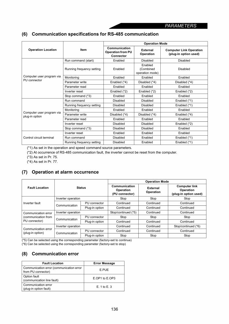
PARAMETERS
(6) Communication specifications for RS-485 communication
(*1) As set in the operation and speed command source parameters.(*2) At occurrence of RS-485 communication fault, the inverter cannot be reset from the computer.(*3) As set in Pr. 75.(*4) As set in Pr. 77.
(7) Operation at alarm occurrence
(*5) Can be selected using the corresponding parameter (factory-set to continue)(*6) Can be selected using the corresponding parameter (factory-set to stop)
(8) Communication error
Operation Location Item
Operation ModeCommunication
Operation from PU Connector
External Operation
Computer Link Operation (plug-in option used)
Computer user program via PU connector
Run command (start) Enabled Disabled Disabled
Running frequency setting EnabledEnabled
(Combined operation mode)
Disabled
Monitoring Enabled Enabled EnabledParameter write Enabled (*4) Disabled (*4) Disabled (*4)Parameter read Enabled Enabled EnabledInverter reset Enabled (*2) Enabled (*2) Enabled (*2)Stop command (*3) Enabled Enabled Enabled
Computer user program via plug-in option
Run command Disabled Disabled Enabled (*1)Running frequency setting Disabled Disabled Enabled (*1)Monitoring Enabled Enabled EnabledParameter write Disabled (*4) Disabled (*4) Enabled (*4)Parameter read Enabled Enabled EnabledInverter reset Disabled Disabled Enabled (*2)Stop command (*3) Disabled Disabled Enabled
Control circuit terminalInverter reset Enabled Enabled EnabledRun command Disabled Enabled Enabled (*1)Running frequency setting Disabled Enabled Enabled (*1)
Fault Location Status
Operation ModeCommunication
Operation(PU connector)
External Operation
Computer link Operation
(plug-in option used)
Inverter faultInverter operation Stop Stop Stop
CommunicationPU connector Continued Continued ContinuedPlug-in option Continued Continued Continued
Communication error (communication from PU connector)
Inverter operation Stop/continued (*5) Continued Continued
CommunicationPU connector Stop Stop StopPlug-in option Continued Continued Continued
Communication error (plug-in option)
Inverter operation Continued Continued Stop/continued (*6)
CommunicationPU connector Continued Continued ContinuedPlug-in option Stop Stop Stop
Fault Location Error MessageCommunication error (communication error from PU connector) E.PUE
Option fault(communication line fault) E.OP1 to E.OP3
Communication error(plug-in option fault) E. 1 to E. 3
136
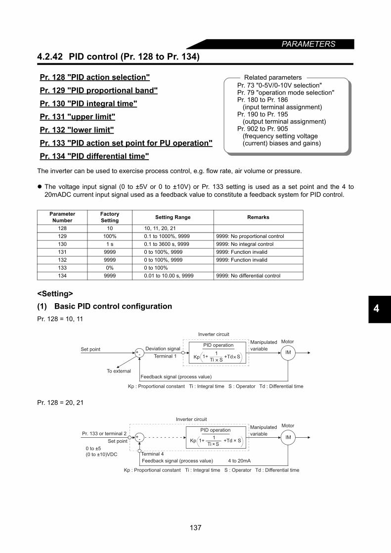
PARAMETERS
4
4.2.42 PID control (Pr. 128 to Pr. 134)
The inverter can be used to exercise process control, e.g. flow rate, air volume or pressure.
The voltage input signal (0 to ±5V or 0 to ±10V) or Pr. 133 setting is used as a set point and the 4 to20mADC current input signal used as a feedback value to constitute a feedback system for PID control.
<Setting>(1) Basic PID control configurationPr. 128 = 10, 11
Pr. 128 = 20, 21
Pr. 128 "PID action selection"Pr. 129 "PID proportional band"Pr. 130 "PID integral time"Pr. 131 "upper limit"Pr. 132 "lower limit"Pr. 133 "PID action set point for PU operation"Pr. 134 "PID differential time"
Parameter Number
FactorySetting Setting Range Remarks
128 10 10, 11, 20, 21129 100% 0.1 to 1000%, 9999 9999: No proportional control130 1 s 0.1 to 3600 s, 9999 9999: No integral control131 9999 0 to 100%, 9999 9999: Function invalid132 9999 0 to 100%, 9999 9999: Function invalid133 0% 0 to 100%134 9999 0.01 to 10.00 s, 9999 9999: No differential control
Related parametersPr. 73 "0-5V/0-10V selection"Pr. 79 "operation mode selection"Pr. 180 to Pr. 186 (input terminal assignment)Pr. 190 to Pr. 195 (output terminal assignment)Pr. 902 to Pr. 905 (frequency setting voltage (current) biases and gains)
+- IMDeviation signal
Feedback signal (process value)
Ti S
11+ +Td SKp
PID operation
To external
Set point
Inverter circuit
Motor
Terminal 1
Kp : Proportional constant Ti : Integral time S : Operator Td : Differential time
Manipulated
variable
+- IM
Ti ×SKp 1+ +Td × S
1
PID operation
4 to 20mAFeedback signal (process value)
Set point
Inverter circuit
Motor
Terminal 4
Manipulated
variablePr. 133 or terminal 2
0 to ±5
(0 to ±10)VDC
Kp : Proportional constant Ti : Integral time S : Operator Td : Differential time
137

PARAMETERS
(2) PID action overview1) PI actionA combination of proportional control action (P) and integral control action (I) for providing a manipulatedvariable in response to deviation and changes with time.
2) PD actionA combination of proportional control action (P) and differential control action (D) for providing a manipulated variable in response to deviation speed to improve the transient characteristic.
3) PID action
[Operation example for stepped changes of process value]
Note: PI action is the sum of P and I actions.
[Operation example for proportional changes of process value]
Note: PD action is the sum of P and D actions.
The PI action and PD action are combined to utilize theadvantages of both actions for control.
Note: The PID action is the sum of P and I and D actions.
Time
Time
Time
Process value
P action
I action
PI action
Deviation Set point
Time
Time
Time
Deviation
P action
D action
PD action
Set point
Processvalue
PID action
I action
y=at2 + bt + c
Time
Deviation
P action
D action
Set point
Processvalue
Time
Time
Time
138
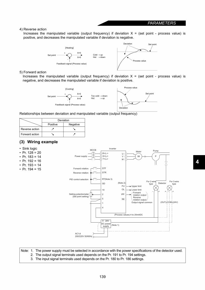
PARAMETERS
4
4) Reverse actionIncreases the manipulated variable (output frequency) if deviation X = (set point - process value) ispositive, and decreases the manipulated variable if deviation is negative.
5) Forward actionIncreases the manipulated variable (output frequency) if deviation X = (set point - process value) isnegative, and decreases the manipulated variable if deviation is positive.
Relationships between deviation and manipulated variable (output frequency)
(3) Wiring example• Sink logic• Pr. 128 = 20• Pr. 183 = 14• Pr. 192 = 16• Pr. 193 = 14• Pr. 194 = 15
DeviationPositive Negative
Reverse action
Forward action
Note: 1. The power supply must be selected in accordance with the power specifications of the detector used.2. The output signal terminals used depends on the Pr. 191 to Pr. 194 settings.3. The input signal terminals used depends on the Pr. 180 to Pr. 186 settings.
X>0
X<0
+
-Process value
Set point
[Heating]
Feedback signal (Process value)
Cold → upHot → down
Deviation Set point
X>0
X<0
+
-
Set pointToo cold → downHot → up
Set point
[Cooling]
Feedback signal (Process value)
Process value
Deviation
MCCB
0 24V
AC1
200/220V 50/60Hz
STF
STR
RT(Note 3)
SD
10
2
5
1
4
U
V
W
(Note 2)
FU
OL
SE
(Process values) 4 to 20mADC
IM P
-+ + +-
(OUT) (24V)
IPF
(Note 1)
Power supply
Forward rotation
Reverse rotation
PID control selection
Setting potentiometer(Set point setting)
Inverter
Motor Pump
Upper limit
Lower limit
Forwardrotation outputReverserotation output
Output signal common
For 2-wiretype Detector
For 3-wiretype
DC powersupply
(COM)
R<L1>
S<L2>
T<L3>
139
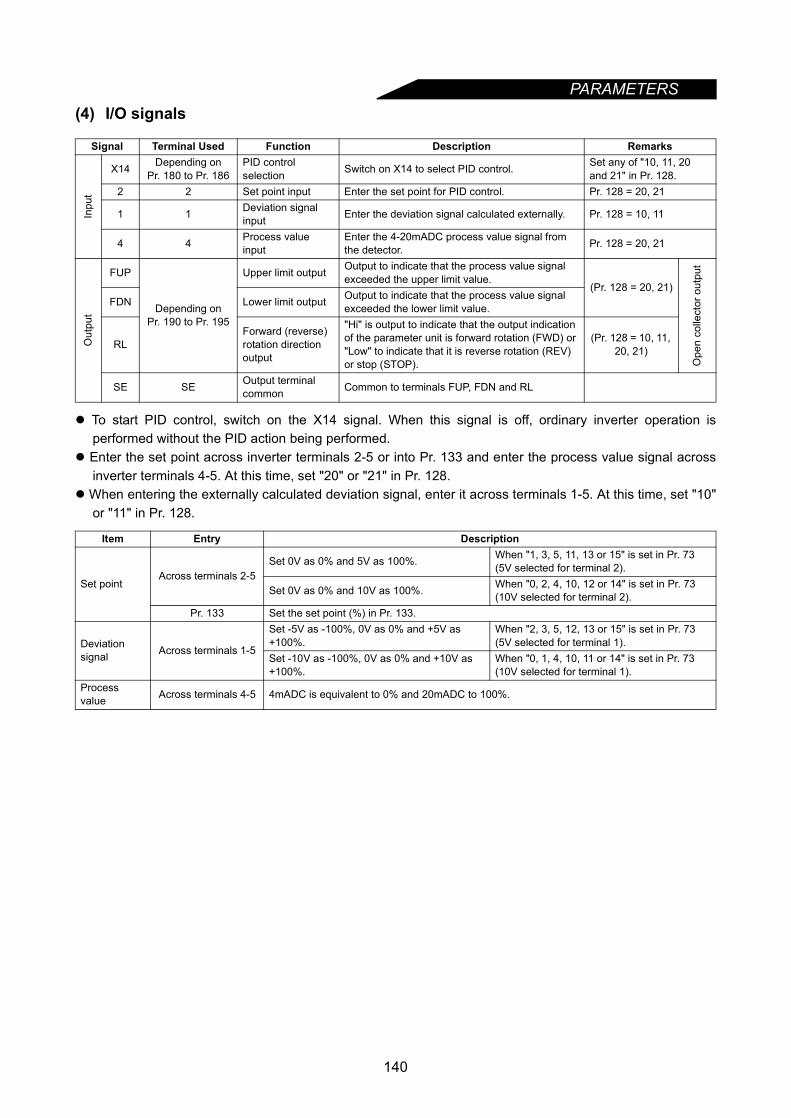
PARAMETERS
(4) I/O signalsTo start PID control, switch on the X14 signal. When this signal is off, ordinary inverter operation isperformed without the PID action being performed.
Enter the set point across inverter terminals 2-5 or into Pr. 133 and enter the process value signal acrossinverter terminals 4-5. At this time, set "20" or "21" in Pr. 128.
When entering the externally calculated deviation signal, enter it across terminals 1-5. At this time, set "10"or "11" in Pr. 128.
Signal Terminal Used Function Description Remarks
Inpu
t
X14 Depending onPr. 180 to Pr. 186
PID control selection Switch on X14 to select PID control. Set any of "10, 11, 20
and 21" in Pr. 128.2 2 Set point input Enter the set point for PID control. Pr. 128 = 20, 21
1 1 Deviation signal input Enter the deviation signal calculated externally. Pr. 128 = 10, 11
4 4 Process value input
Enter the 4-20mADC process value signal from the detector. Pr. 128 = 20, 21
Out
put
FUP
Depending onPr. 190 to Pr. 195
Upper limit output Output to indicate that the process value signal exceeded the upper limit value.
(Pr. 128 = 20, 21)
Ope
n co
llect
or o
utpu
t
FDN Lower limit output Output to indicate that the process value signal exceeded the lower limit value.
RLForward (reverse) rotation direction output
"Hi" is output to indicate that the output indication of the parameter unit is forward rotation (FWD) or "Low" to indicate that it is reverse rotation (REV) or stop (STOP).
(Pr. 128 = 10, 11, 20, 21)
SE SE Output terminal common Common to terminals FUP, FDN and RL
Item Entry Description
Set pointAcross terminals 2-5
Set 0V as 0% and 5V as 100%. When "1, 3, 5, 11, 13 or 15" is set in Pr. 73 (5V selected for terminal 2).
Set 0V as 0% and 10V as 100%. When "0, 2, 4, 10, 12 or 14" is set in Pr. 73 (10V selected for terminal 2).
Pr. 133 Set the set point (%) in Pr. 133.
Deviation signal Across terminals 1-5
Set -5V as -100%, 0V as 0% and +5V as +100%.
When "2, 3, 5, 12, 13 or 15" is set in Pr. 73 (5V selected for terminal 1).
Set -10V as -100%, 0V as 0% and +10V as +100%.
When "0, 1, 4, 10, 11 or 14" is set in Pr. 73 (10V selected for terminal 1).
Process value Across terminals 4-5 4mADC is equivalent to 0% and 20mADC to 100%.
140

PARAMETERS
4
(5) Parameter setting
(6) Adjustment procedure
Parameter Number Setting Name Description
128
10
PID action selection
For heating, pressure control, etc. Deviation value signal input(terminal 1)
PID reverse action
11 For cooling, etc. PID forward action
20 For heating, pressure control, etc. Set point (terminal 2 or Pr. 133), process value input (terminal 4)
PID reverse action
21 For cooling, etc. PID forward action
1290.1 to 1000% PID proportional
band
If the proportional band is narrow (parameter setting is small), the manipulated variable varies greatly with a slight change of the process value. Hence, as the proportional band narrows, the response sensitivity (gain) improves but the stability deteriorates, e.g. hunting occurs.Gain K = 1/proportional band
9999 No proportional control
1300.1 to 3600 s
PID integral time
Time required for the integral (I) action to provide the same manipulated variable as that for the proportional (P) action. As the integral time decreases, the set point is reached earlier but hunting occurs more easily.
9999 No integral control.
1310 to 100%
Upper limitSet the upper limit. If the feedback value exceeds the setting, the FUP signal is output. (Process value of 4mA is equivalent to 0% and 20mA to 100%.)
9999 No function
1320 to 100%
Lower limit
Set the lower limit. (If the process value falls below the setting range, an alarm can be output. In this case, the process value of 4mA is equivalent to 0% and 20mA to 100%.)
9999 No function
133 0 to 100%PID action set point for PU operation
Only valid for the PU command in the PU operation or PU/external combined mode.For external operation, the voltage across 2-5 is the set point.(Pr. 902 value is equivalent to 0% and Pr. 903 value to 100%.)
1340.01 to 10.00 s PID differential
time
Time only required for the differential (D) action to provide the same process value as that for the proportional (P) action. As the differential time increases, greater response is made to a deviation change.
9999 No differential control.
Set the I/O terminals for PID control.(Pr. 180 to Pr. 186, Pr. 190 to Pr. 195)Pr. 128 = 10, 11, 20, 21
Parameter setting
Terminal setting
Switch X14 signal on.
Run
Adjust the PID control parameters, Pr. 128 to Pr. 134.
141

PARAMETERS
(7) Calibration example
(A detector of 4mA at 0°C (32°F) and 20mA at 50°C (122°F) is used to adjust the room temperature to 25°C(77°F) under PID control.The set point is given to across inverter terminals 2-5 (0-5V).)
Yes
No
START
Determine the set point.
Determine the set point of theitem to be adjusted.
Convert the set point into %.
Calculate the ratio of the setpoint to the detector output.
Make calibration.
Set the set point.
Enter a voltage to acrossterminals 2-5 according tothe set point (%).
Operation
Set the proportional band (Pr.129)and integral time (Pr. 130) to slightly
higher values and the differential
time (Pr. 134) to "9999" (functioninvalid) and switch on the start signal.
Is the process value steady?
Adjust parameters.
Set the proportional band (Pr. 129)and integral time (Pr. 130) to slightlyhigher values and set the differentialtime (Pr.134) to a slightly lower valueto stabilize the process value.
END
Optimize parameters.
While the process value is steady,the proportional band (Pr. 129) and integral time may (Pr. 130) be reduced and thedifferential time (Pr. 134) increasedthroughout the operation.
......Set the room temperature to 25°C (77°F).Set Pr. 128 and switch on the X14 signal to enable PID control.
......Detector specificationsWhen the detector used has the specifications that 0°C is equivalent to4mA and 50°C (122°F) to 20mA, the set point of 25°C (77°F) is 50%because 4mA is equivalent to 0% and 20mA to 100%.
......When the set point setting input (0 to 5V) and detector output (4 to20mA) must be calibrated, make the following calibration*.
......Set point = 50%Since the specifications of terminal 2 are such that 0% is equivalent to0V and 100% to 5V, enter 2.5V into terminal 2.
......For PU operation, set the set point (0 to 100%) in Pr. 133.During operation, set the proportional band (Pr. 129) and integral time(Pr. 130) to slightly higher values and set the differential time to "9999"(function invalid). In accordance with the system operation, reduce theproportional band and increase integral time (Pr. 130) for the slowresponce system, gradually increase the differential time (Pr. 134) usingdifferential control.
*When calibration is required, use Pr. 902 and Pr. 903 (terminal 2) or Pr. 904 and Pr. 905 (terminal 4)to calibrate the detector output and set point setting input.Perform calibration in the PU mode during an inverter stop.
142
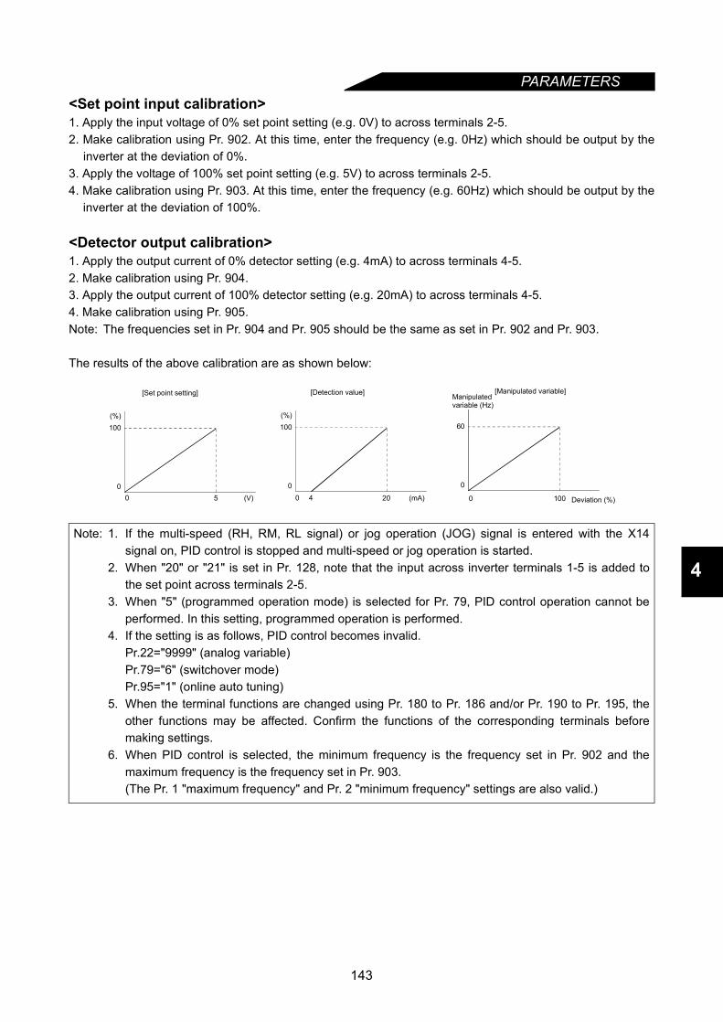
PARAMETERS
4
<Set point input calibration>1. Apply the input voltage of 0% set point setting (e.g. 0V) to across terminals 2-5.2. Make calibration using Pr. 902. At this time, enter the frequency (e.g. 0Hz) which should be output by the
inverter at the deviation of 0%.3. Apply the voltage of 100% set point setting (e.g. 5V) to across terminals 2-5.4. Make calibration using Pr. 903. At this time, enter the frequency (e.g. 60Hz) which should be output by the
inverter at the deviation of 100%.
<Detector output calibration>1. Apply the output current of 0% detector setting (e.g. 4mA) to across terminals 4-5.2. Make calibration using Pr. 904.3. Apply the output current of 100% detector setting (e.g. 20mA) to across terminals 4-5.4. Make calibration using Pr. 905.Note: The frequencies set in Pr. 904 and Pr. 905 should be the same as set in Pr. 902 and Pr. 903.
The results of the above calibration are as shown below:
Note: 1. If the multi-speed (RH, RM, RL signal) or jog operation (JOG) signal is entered with the X14signal on, PID control is stopped and multi-speed or jog operation is started.
2. When "20" or "21" is set in Pr. 128, note that the input across inverter terminals 1-5 is added tothe set point across terminals 2-5.
3. When "5" (programmed operation mode) is selected for Pr. 79, PID control operation cannot beperformed. In this setting, programmed operation is performed.
4. If the setting is as follows, PID control becomes invalid.Pr.22="9999" (analog variable)Pr.79="6" (switchover mode)Pr.95="1" (online auto tuning)
5. When the terminal functions are changed using Pr. 180 to Pr. 186 and/or Pr. 190 to Pr. 195, theother functions may be affected. Confirm the functions of the corresponding terminals beforemaking settings.
6. When PID control is selected, the minimum frequency is the frequency set in Pr. 902 and themaximum frequency is the frequency set in Pr. 903.(The Pr. 1 "maximum frequency" and Pr. 2 "minimum frequency" settings are also valid.)
100
00 5 (V)
(%)
[Set point setting]
100
0
0 20 (mA)
(%)
4
[Detection value]
60
0
0 100 Deviation (%)
[Manipulated variable]Manipulatedvariable (Hz)
143
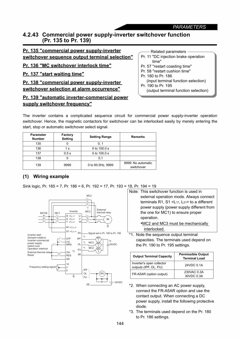
PARAMETERS
4.2.43 Commercial power supply-inverter switchover function(Pr. 135 to Pr. 139)
Pr. 135 "commercial power supply-inverterswitchover sequence output terminal selection"
Pr. 136 "MC switchover interlock time"
Pr. 137 "start waiting time"
Pr. 138 "commercial power supply-inverter switchover selection at alarm occurrence"
Pr. 139 "automatic inverter-commercial powersupply switchover frequency"
The inverter contains a complicated sequence circuit for commercial power supply-inverter operationswitchover. Hence, the magnetic contactors for switchover can be interlocked easily by merely entering thestart, stop or automatic switchover select signal.
(1) Wiring example
Sink logic, Pr. 185 = 7, Pr. 186 = 6, Pr. 192 = 17, Pr. 193 = 18, Pr. 194 = 19
Parameter Number
FactorySetting Setting Range Remarks
135 0 0, 1136 1 s 0 to 100.0 s137 0.5 s 0 to 100.0 s138 0 0,1
139 9999 0 to 60.0Hz, 9999 9999: No automatic switchover
Note: This switchover function is used in external operation mode. Always connect terminals R1, S1 <L11, L21> to a different power supply (power supply different from the one for MC1) to ensure proper operation.•MC2 and MC3 must be mechanically
interlocked.*1. Note the sequence output terminal
capacities. The terminals used depend on the Pr. 190 to Pr. 195 settings.
*2. When connecting an AC power supply, connect the FR-A5AR option and use the contact output. When connecting a DC power supply, install the following protective diode.
*3. The terminals used depend on the Pr. 180 to Pr. 186 settings.
Related parametersPr. 11 "DC injection brake operation
time"Pr. 57 "restart coasting time"Pr. 58 "restart cushion time"Pr. 180 to Pr. 186
(input terminal function selection)Pr. 190 to Pr. 195
(output terminal function selection)
MC1
STF
CSMRS
RES
SD
10
2
5
U
V
W
MC2
MC3
IM
IPF
OL
SE
*1
*1
*1
*2MC3
MC2
24VDC
MC1
FU
MCCB
MC2
MC3*3OH
SU
IPF
OL
FU
SE24VDC
External thermal relayReset
Frequency setting signal
Externalthermal relay
Signal set in Pr. 190 to Pr. 195
Inverter
Operation interlock
Inverter start (forward rotation)Inverter-commercial power supply switch-over
RA
R L< >
< >
< >
< >
< >
1
S L2
T L3
R1 L11
S1 L21
Output Terminal Capacity Permissible Output Terminal Load
Inverter's open collector outputs (IPF, OL, FU) 24VDC 0.1A
FR-A5AR (option output) 230VAC 0.3A30VDC 0.3A
144

PARAMETERS
4
• Roles of the magnetic contactors (MC1, MC2, MC3)
<I/O signals>1) When this function is used (Pr. 135 = "1"), the input signals are switched on-off as indicated below:
Note: • In the above MC operation field, [-] indicates that MC1 is on, MC2 is off and MC3 is on in inverteroperation and MC1 is on, MC2 is on and MC3 is off in commercial power supply operation.[Unchanged] indicates that the status before signal-on or -off is held.
• The CS signal only functions when the MRS signal is on. STF (STR) only functions when MRS andCS are on.
• MC1 switches off when an inverter fault occurs.• If the MRS signal is not switched on, neither commercial power supply nor inverter operation can be
performed.• For the RES signal, reset input acceptance selection can be made using reset selection (Pr. 75).
2) The output signals are output as follows:
Magnetic Contactor Place of Installation Role
MC1 Between power supply and inverter Normally shorted with the following exception:Opened only when an inverter fault occurs (shorted again by resetting)
MC2 Between power supply and motor
Shorted for commercial power supply operation, opened for inverter operation.Shorted when an inverter fault occurs (selected with parameter, except for external thermal relay operation)
MC3 Between inverter output and motorShorted for inverter operation, opened for commercial power supply operationOpened when an inverter fault occurs
Signal Terminal Used Function On-OffMC Operation (:ON, ×:OFF)
MC1 MC2 MC3
MRS MRS Operation enable/disable selection
Commercial power supply-inverter operation enable..................................ONCommercial power supply-inverter operation disable..................................OFF
−
×
−
Unchanged
CS Depending onPr. 180 to Pr.186
Inverter-commercial power supply switchover
Inverter operation ONCommercial power supply operation................OFF
×
×
STF(STR)
STF(STR)
Inverter operation command (invalid for commercial power supply) (Note)
Forward (reverse) rotation..................................ONStop..........................OFF
×
×
OH Depending onPr. 180 to Pr.186
External thermal relay input
Motor normal..........ONMotor fault................OFF
×
−
×
−
×
RES RES Operating condition initialization
Initialization.............ONNormal operation...OFF
Unchanged
×
−
Unchanged−
Signal Terminal Used DescriptionMC1
Depending on Pr. 190 to Pr. 195
MC1's operation signal is outputMC2 MC2's operation signal is outputMC3 MC3's operation signal is output
145
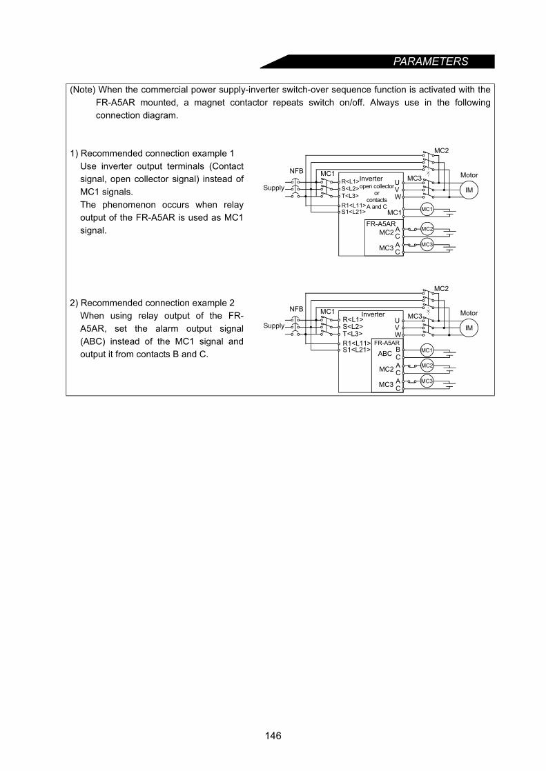
PARAMETERS
(Note) When the commercial power supply-inverter switch-over sequence function is activated with theFR-A5AR mounted, a magnet contactor repeats switch on/off. Always use in the followingconnection diagram.
1) Recommended connection example 1Use inverter output terminals (Contactsignal, open collector signal) instead ofMC1 signals.The phenomenon occurs when relayoutput of the FR-A5AR is used as MC1signal.
2) Recommended connection example 2When using relay output of the FR-A5AR, set the alarm output signal(ABC) instead of the MC1 signal andoutput it from contacts B and C.
IM
NFB MC1
MC2
WVU MC3
MC1 MC1
MC2
MC3
FR-A5ARAC
Supply
MotorInverter
MC2
AC
MC3
S1<L21>R1<L11>T<L3>S<L2>R<L1>
open collectoror
contactsA and C
IM
NFB MC1
MC2
WVU MC3
ABC MC1FR-A5AR
Supply
MotorInverter
MC2
CMC2
MC3
AC
MC3
B
AC
S1<L21>R1<L11>T<L3>S<L2>R<L1>
146

PARAMETERS
4
(2) Parameter setting
Note: 1. Pr. 139 functions when Pr. 135 setting is other than "0".2. When the motor started by the inverter reaches the automatic switchover frequency, inverter
operation is switched to commercial power supply operation. If the inverter's operation commandvalue is then lowered to or below the switchover frequency, commercial power supply operation isnot automatically switched to inverter operation.Switch off the inverter operation command signal (STF or STR) to switch commercial power supplyoperation to inverter operation and decelerate the motor to a stop.
<Operation sequence>
Parameter Number Name Setting Description
135
Commercial power supply-inverter switchover sequence output terminal selection
0 Sequence output is not provided. (Pr. 136, Pr. 137, Pr. 138 and Pr. 139 settings are ignored.)
1
Sequence output is provided.When MC1 to MC3 are assigned with Pr. 190 to Pr. 195 (output terminal function selection), open collector outputs are provided. When they are not assigned, relay outputs are provided from the FR-A5AR (option).
136 MC switchover interlock time 0 to 100.0 s Sets the MC2 and MC3 operation interlock time.
137 Start waiting time 0 to 100.0 s Set a slightly longer (about 0.3 to 0.5 s) value than the time from when the ON signal enters inverter operation MC3 to when it actually switches on.
138
Commercial power supply-inverter switchover selection at alarm occurrence
0Stops inverter operation and coasts the motor.The inverter stops when an inverter fault occurs (both MC2 and MC3 switch off).
1
Stops inverter operation and automatically switches inverter operation to commercial power supply operation.When an inverter fault occurs, inverter operation is automatically switched to commercial power supply operation (MC2: ON, MC3: OFF).
139
Automatic inverter-commercial power supply switchover frequency
0 to 60.0Hz
The motor is started and run by the inverter up to the set frequency, and when the output frequency reaches or exceeds the set frequency, inverter operation is automatically switched to commercial power supply operation. Start and stop are controlled by the inverter operation command (STF or STR).
9999 Automatic switchover is not done.
ON
OFF
ON
OFF
ON
OFF
ON
OFF
(MRS)
(STF)
(CS)
ON
OFF(MC1)
ON
OFF(MC3)
ON
OFF(MC2)
A A,B AC,D
A C,DB Each timerA: Pr. 136 MC switch-over interlock time B: Pr. 137 MC3 start commencement (start waiting time)C: Pr. 57 (reset time)D: Pr. 58 (switch-over cushion time)
Power
Operation interlock
Inverter operation command
Inverter-commercial power supply switch-over
Commercial power supply-inverter switch-over
Commercial power supply-inverter switch-over
Commercial power supply-inverter switch-over
Each timer
Operating status(Motor speed)
Off for inverter fault only
Operation commandActual operation (Note)
Coast to stop
Commercial power supply stop
Inverteroperation
Coasting
Commercial powersupply operation
Coasting Inverter operation
Stop Inverter operation
ON: Operation enable
OFF: Operation disable
ON: Forward rotation
ON: Inverter operation
OFF: Stop
OFF: Commercial power supply operation
Note: Indicates a delay until MC switches on.
147
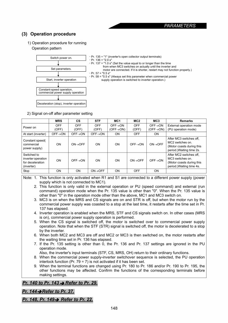
PARAMETERS
(3) Operation procedure
1) Operation procedure for runningOperation pattern
2) Signal on-off after parameter setting
MRS CS STF MC1 MC2 MC3 Remarks
Power on OFF(OFF)
OFF(OFF)
OFF(OFF)
OFF→ON(OFF→ON)
OFF(OFF)
OFF→ON(OFF→ON)
External operation mode (PU operation mode)
At start (inverter) OFF→ON OFF→ON OFF→ON ON OFF ON
Constant speed( commercial power supply)
ON ON→OFF ON ON OFF→ON ON→OFF
After MC3 switches off, MC2 switches on.(Motor coasts during this period.)Waiting time 2s.
Switched to inverter operation for deceleration (inverter)
ON OFF→ON ON ON ON→OFF OFF→ON
After MC2 switches off, MC3 switches on.(Motor coasts during this period.)Waiting time 4s.
Stop ON ON ON→OFF ON OFF ON
Note: 1. This function is only activated when R1 and S1 are connected to a different power supply (powersupply which is not connected to MC1).
2. This function is only valid in the external operation or PU (speed command) and external (runcommand) operation mode when the Pr. 135 value is other than "0". When the Pr. 135 value isother than "0" in the operation mode other than the above, MC1 and MC3 switch on.
3. MC3 is on when the MRS and CS signals are on and STR is off, but when the motor run by thecommercial power supply was coasted to a stop at the last time, it restarts after the time set in Pr.137 has elapsed.
4. Inverter operation is enabled when the MRS, STF and CS signals switch on. In other cases (MRSis on), commercial power supply operation is performed.
5. When the CS signal is switched off, the motor is switched over to commercial power supplyoperation. Note that when the STF (STR) signal is switched off, the motor is decelerated to a stopby the inverter.
6. When both MC2 and MC3 are off and MC2 or MC3 is then switched on, the motor restarts afterthe waiting time set in Pr. 136 has elapsed.
7. If the Pr. 135 setting is other than 0, the Pr. 136 and Pr. 137 settings are ignored in the PUoperation mode.Also, the inverter's input terminals (STF, CS, MRS, OH) return to their ordinary functions.
8. When the commercial power supply-inverter switchover sequence is selected, the PU operationinterlock function (Pr. 79 = 7) is not activated if it has been set.
9. When the terminal functions are changed using Pr. 180 to Pr. 186 and/or Pr. 190 to Pr. 195, theother functions may be affected. Confirm the functions of the corresponding terminals beforemaking settings.
Pr. 135 = "1" (inverter's open collector output terminals) Pr. 136 = "2.0 s" Pr. 137 = "1.0 s" (Set the value equal to or longer than the time from when MC3 switches on actually until the inverter and motor are connected. If it is shorter, restart may not function properly.) Pr. 57 = "0.5 s" Pr. 58 = "0.5 s" (Always set this parameter when commercial power supply operation is switched to inverter operation.)
Constant-speed operation,commercial power supply operation
Switch power on.
Set parameters.
Start, inverter operation
Deceleration (stop), inverter operation
Pr. 140 to Pr. 143 Refer to Pr. 29.
Pr. 144 Refer to Pr. 37.
Pr. 148, Pr. 149 Refer to Pr. 22.
148
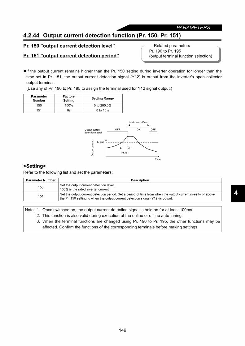
149
PARAMETERS
4
4.2.44 Output current detection function (Pr. 150, Pr. 151)
Pr. 150 "output current detection level"
Pr. 151 "output current detection period"
If the output current remains higher than the Pr. 150 setting during inverter operation for longer than thetime set in Pr. 151, the output current detection signal (Y12) is output from the inverter's open collectoroutput terminal.(Use any of Pr. 190 to Pr. 195 to assign the terminal used for Y12 signal output.)
<Setting>Refer to the following list and set the parameters:
Parameter Number
FactorySetting Setting Range
150 150% 0 to 200.0%151 0s 0 to 10 s
Parameter Number Description
150 Set the output current detection level.100% is the rated inverter current.
151 Set the output current detection period. Set a period of time from when the output current rises to or above the Pr. 150 setting to when the output current detection signal (Y12) is output.
Note: 1. Once switched on, the output current detection signal is held on for at least 100ms.2. This function is also valid during execution of the online or offline auto tuning.3. When the terminal functions are changed using Pr. 190 to Pr. 195, the other functions may be
affected. Confirm the functions of the corresponding terminals before making settings.
Related parametersPr. 190 to Pr. 195(output terminal function selection)
Pr.151
Pr.150
OFF ON OFF
Minimum 100ms
Time
Output currentdetection signal
Out
put c
urre
nt
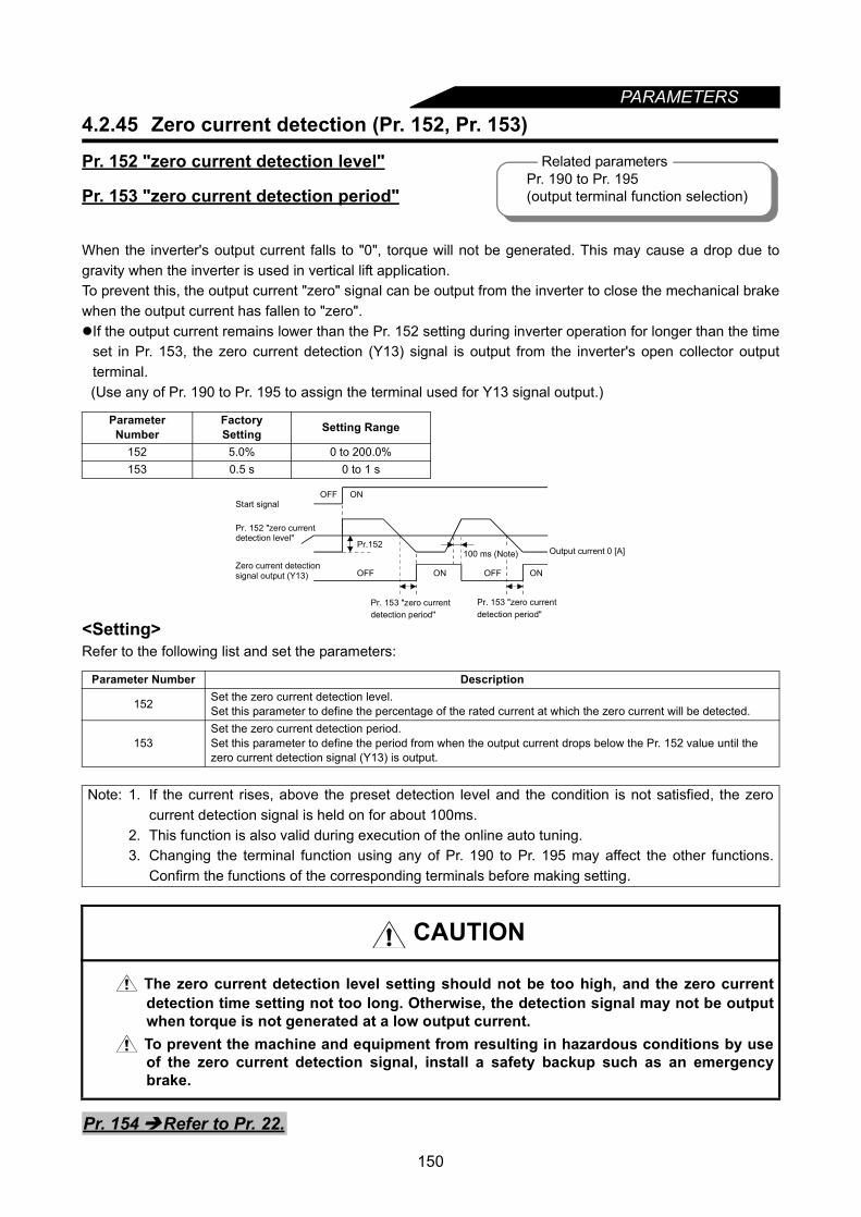
PARAMETERS
4.2.45 Zero current detection (Pr. 152, Pr. 153)Pr. 152 "zero current detection level"
Pr. 153 "zero current detection period"
When the inverter's output current falls to "0", torque will not be generated. This may cause a drop due togravity when the inverter is used in vertical lift application.To prevent this, the output current "zero" signal can be output from the inverter to close the mechanical brakewhen the output current has fallen to "zero".If the output current remains lower than the Pr. 152 setting during inverter operation for longer than the time
set in Pr. 153, the zero current detection (Y13) signal is output from the inverter's open collector outputterminal.(Use any of Pr. 190 to Pr. 195 to assign the terminal used for Y13 signal output.)
<Setting>Refer to the following list and set the parameters:
Parameter Number
FactorySetting Setting Range
152 5.0% 0 to 200.0%153 0.5 s 0 to 1 s
Parameter Number Description
152 Set the zero current detection level.Set this parameter to define the percentage of the rated current at which the zero current will be detected.
153Set the zero current detection period.Set this parameter to define the period from when the output current drops below the Pr. 152 value until the zero current detection signal (Y13) is output.
Note: 1. If the current rises, above the preset detection level and the condition is not satisfied, the zerocurrent detection signal is held on for about 100ms.
2. This function is also valid during execution of the online auto tuning.3. Changing the terminal function using any of Pr. 190 to Pr. 195 may affect the other functions.
Confirm the functions of the corresponding terminals before making setting.
CAUTION
The zero current detection level setting should not be too high, and the zero currentdetection time setting not too long. Otherwise, the detection signal may not be outputwhen torque is not generated at a low output current.
To prevent the machine and equipment from resulting in hazardous conditions by useof the zero current detection signal, install a safety backup such as an emergencybrake.
Related parametersPr. 190 to Pr. 195(output terminal function selection)
Output current 0 [A]
OFF ON
OFF ON
Pr.152
OFF ON
100 ms (Note)
Start signal
Pr. 152 "zero currentdetection level"
Zero current detectionsignal output (Y13)
Pr. 153 "zero currentdetection period"
Pr. 153 "zero currentdetection period"
Pr. 154 Refer to Pr. 22.
150
PARAMETERS
4
4.2.46 RT signal activated condition selection (Pr. 155)
Set the condition of activating the RT terminal to select the second control functions by switching on-off theRT signal.
<Setting>Refer to the following table and set the parameters:
4.2.47 Stall prevention function and current limit function (Pr. 156)
You can make setting to prevent stall caused by overcurrent and/or to prevent the inverter from resulting inan overcurrent trip (to disable fast-response current restriction that limits the current) when an excessivecurrent flows due to sudden load fluctuation or ON-OFF on the output side of a running inverter. An OL signaloutput delay can be set in Pr. 157.
Stall preventionAutomatically change the output speed of the inverter to reduce the amount of current when the currentflow exceeds the current limit level.
Fast response current limitShut off the output of the inverter to prevent overcurrent when the current flows exceeds the currentrestriction value.
Pr. 155 "RT signal activated condition"
Parameter Number
FactorySetting Setting Range
155 0 0, 10
Pr. 155 Setting Description0 Made valid immediately by switching the RT signal on-off.
10 Made valid only when the RT signal is on at constant speed.(Invalid during acceleration/deceleration)
Pr. 156 "stall prevention operation selection"
Parameter Number Factory Setting Setting Range
156 0 0 to 31, 100, 101
Related parametersPr. 14 "load pattern selection"Pr. 44 to Pr. 49(second function selection)Pr. 81 "number of motor poles"Pr. 180 to Pr. 186(input terminal function selection)
Related parametersPr. 22 "stall prevention operation level"Pr. 23 "stall prevention operation level
compensation factor at double speed"Pr. 48 "second stall prevention operation
current"Pr. 49 "second stall prevention operation
frequency"Pr. 114 "third stall prevention operation
current"Pr. 115 "third stall prevention operation
frequency"Pr. 154 "voltage reduction selection
during stall prevention operation"Pr. 157 "OL signal output waiting time"
151
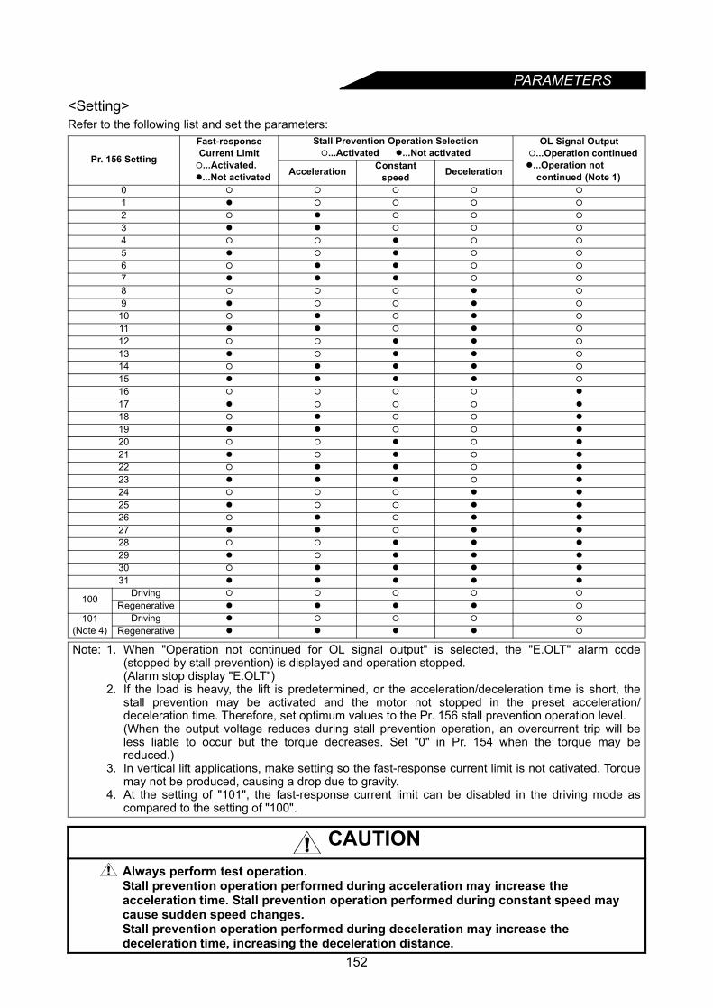
PARAMETERS
<Setting>Refer to the following list and set the parameters:
Pr. 156 Setting
Fast-response Current Limit
...Activated. ...Not activated
Stall Prevention Operation Selection...Activated ...Not activated
OL Signal Output ...Operation continued ...Operation not continued (Note 1)Acceleration Constant
speed Deceleration
0
1
2
3
4
5
6
7
8
9
10
11
12
13
14
15
16
17
18
19
20
21
22
23
24
25
26
27
28
29
30
31
100 Driving
Regenerative
101(Note 4)
Driving
Regenerative
Note: 1. When "Operation not continued for OL signal output" is selected, the "E.OLT" alarm code(stopped by stall prevention) is displayed and operation stopped.(Alarm stop display "E.OLT")
2. If the load is heavy, the lift is predetermined, or the acceleration/deceleration time is short, thestall prevention may be activated and the motor not stopped in the preset acceleration/deceleration time. Therefore, set optimum values to the Pr. 156 stall prevention operation level.(When the output voltage reduces during stall prevention operation, an overcurrent trip will beless liable to occur but the torque decreases. Set "0" in Pr. 154 when the torque may bereduced.)
3. In vertical lift applications, make setting so the fast-response current limit is not cativated. Torquemay not be produced, causing a drop due to gravity.
4. At the setting of "101", the fast-response current limit can be disabled in the driving mode ascompared to the setting of "100".
CAUTION Always perform test operation.Stall prevention operation performed during acceleration may increase the acceleration time. Stall prevention operation performed during constant speed may cause sudden speed changes.Stall prevention operation performed during deceleration may increase the deceleration time, increasing the deceleration distance.
152
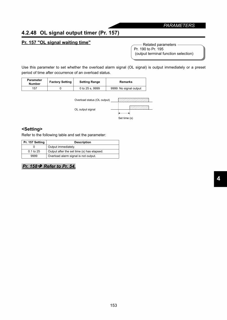
153
PARAMETERS
4
4.2.48 OL signal output timer (Pr. 157)
Pr. 157 "OL signal waiting time"
Use this parameter to set whether the overload alarm signal (OL signal) is output immediately or a presetperiod of time after occurrence of an overload status.
<Setting>Refer to the following table and set the parameter:
Parameter Number Factory Setting Setting Range Remarks
157 0 0 to 25 s, 9999 9999: No signal output
Pr. 157 Setting Description0 Output immediately.
0.1 to 25 Output after the set time (s) has elapsed.9999 Overload alarm signal is not output.
Related parametersPr. 190 to Pr. 195 (output terminal function selection)
Set time (s)
Overload status (OL output)
OL output signal
Pr. 158 Refer to Pr. 54.

PARAMETERS
4.2.49 User group selection (Pr. 160, Pr. 173 to Pr. 176)Pr. 160 "user group read selection"Pr. 173 "user group 1 registration"Pr. 174 "user group 1 deletion"Pr. 175 "user group 2 registration"Pr. 176 "user group 2 deletion"• Pr. 160 "user group read selection" is used to limit the parameters which may be read.• From among all parameters, a total of 32 parameters can be registered to two different user groups.The registered parameters may only be accessed for reading and writing.Parameters other than those registered to the user groups cannot be read.
<Examples of use>(1) Parameter registration to user group (when registering Pr. 3 to user group 1)
(2) Parameter deletion from user group (when deleting Pr. 5 from user group 1)
(3) By setting the required value in Pr. 160, make the user groups valid or invalid.
Parameter Number Factory Setting Setting Range Remarks160 0 0, 1, 10, 11173 0 0 to 999174 0 0 to 999, 9999 9999: Batch deletion175 0 0 to 999176 0 0 to 999, 9999 9999: Batch deletion
Pr. 160 Setting Description0 All parameters can be accessed for reading and writing (factory setting)1 Parameters registered to user group 1 may only be accessed for reading and writing.10 Parameters registered to user group 2 may only be accessed for reading and writing.11 Parameters registered to user groups 1 and 2 may only be accessed for reading and writing.
Note: 1. Pr. 77, Pr. 160 and Pr. 991 values can always be read independently of the user group setting.2. When Pr. 173 or Pr. 174 is read, the number of parameters registered to user group 1 appears.
When Pr. 175 or Pr. 176 is read, the number of parameters registered to user group 2 appears.3. "0" set in the second digit of the 2-digit Pr. 160 setting is not displayed. However, it is displayed
when "0" is set in the first digit only.4. When "9999" is set in Pr. 174 or Pr. 176, the parameters registered to the corresponding user
group is batch-deleted.
Pr. 162 to Pr. 165 Refer to Pr. 57.
Pr. 173 reading
1.5 s
The number of parameters registered for user setting appears.
Using the key, choose the parameter number to be registered.
Pr. 3 is registered to user group 1.
Using the key, move to the next parameter to be registered. Using the key, make registration.
.....
Flickering
.....
.....
.....
Pr. 174 reading
1.5 s
The number of parameters registered for user setting appears.
Using the key, choose the parameter number to be deleted.
Pr. 5 is deleted from user group 1.
Using the key, choose the parameter to be deleted. Using the key, make deletion.
.....
Flickering
.....
.....
.....
154
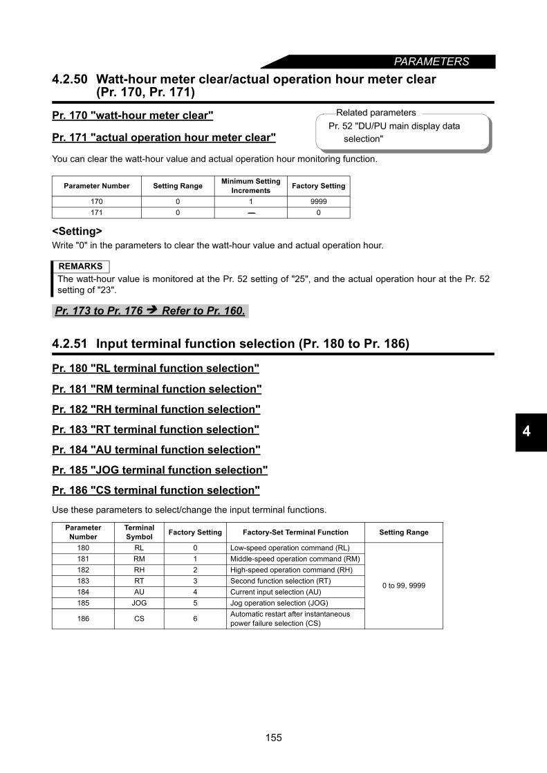
PARAMETERS
4
4.2.50 Watt-hour meter clear/actual operation hour meter clear (Pr. 170, Pr. 171)
Pr. 170 "watt-hour meter clear"
Pr. 171 "actual operation hour meter clear"
You can clear the watt-hour value and actual operation hour monitoring function.
<Setting>Write "0" in the parameters to clear the watt-hour value and actual operation hour.
4.2.51 Input terminal function selection (Pr. 180 to Pr. 186)
Pr. 180 "RL terminal function selection"
Pr. 181 "RM terminal function selection"
Pr. 182 "RH terminal function selection"
Pr. 183 "RT terminal function selection"
Pr. 184 "AU terminal function selection"
Pr. 185 "JOG terminal function selection"
Pr. 186 "CS terminal function selection"Use these parameters to select/change the input terminal functions.
Parameter Number Setting Range Minimum Setting Increments Factory Setting
170 0 1 9999171 0 ------- 0
REMARKSThe watt-hour value is monitored at the Pr. 52 setting of "25", and the actual operation hour at the Pr. 52setting of "23".
Pr. 173 to Pr. 176 Refer to Pr. 160.
Parameter Number
Terminal Symbol Factory Setting Factory-Set Terminal Function Setting Range
180 RL 0 Low-speed operation command (RL)
0 to 99, 9999
181 RM 1 Middle-speed operation command (RM)182 RH 2 High-speed operation command (RH)183 RT 3 Second function selection (RT)184 AU 4 Current input selection (AU)185 JOG 5 Jog operation selection (JOG)
186 CS 6 Automatic restart after instantaneous power failure selection (CS)
Related parametersPr. 52 "DU/PU main display data selection"
155
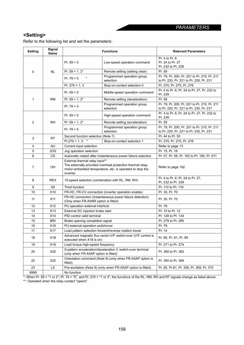
PARAMETERS
<Setting>Refer to the following list and set the parameters:*: When Pr. 59 = "1 or 2", Pr. 79 = "5", and Pr. 270 = "1 or 3", the functions of the RL, RM, RH and RT signals change as listed above.**: Operated when the relay contact "opens".
Setting Signal Name Functions Relevant Parameters
0 RL
Pr. 59 = 0 Low-speed operation commandPr. 4 to Pr. 6Pr. 24 to Pr. 27Pr. 232 to Pr. 239
Pr. 59 = 1, 2* Remote setting (setting clear) Pr. 59
Pr. 79 = 5 * Programmed operation group selection
Pr. 79, Pr. 200, Pr. 201 to Pr. 210, Pr. 211 to Pr. 220, Pr. 221 to Pr. 230, Pr. 231
Pr. 270 = 1, 3 Stop-on-contact selection 0 Pr. 270, Pr. 275, Pr. 276
1 RM
Pr. 59 = 0 Middle-speed operation command Pr. 4 to Pr. 6, Pr. 24 to Pr. 27, Pr. 232 to Pr. 239
Pr. 59 = 1, 2* Remote setting (deceleration) Pr. 59
Pr. 79 = 5 Programmed operation group selection
Pr. 79, Pr. 200, Pr. 201 to Pr. 210, Pr. 211 to Pr. 220, Pr. 221 to Pr. 230, Pr. 231
2 RH
Pr. 59 = 0 High-speed operation command Pr. 4 to Pr. 6, Pr. 24 to Pr. 27, Pr. 232 to Pr. 239
Pr. 59 = 1, 2* Remote setting (acceleration) Pr. 59
Pr. 79 = 5 Programmed operation group selection
Pr. 79, Pr. 200, Pr. 201 to Pr. 210, Pr. 211 to Pr. 220, Pr. 221 to Pr. 230, Pr. 231
3 RT Second function selection (Note 7) Pr. 44 to Pr. 50Pr.270 = 1, 3 * Stop-on-contact selection 1 Pr. 270, Pr. 275, Pr. 276
4 AU Current input selection Refer to page 135 JOG Jog operation selection Pr. 15, Pr. 166 CS Automatic restart after instantaneous power failure selection Pr. 57, Pr. 58, Pr. 162 to Pr. 165, Pr. 611
7 OH
External thermal relay input**The externally provided overheat protection thermal relay, motor-embedded temperature, etc. is operated to stop the inverter.
Refer to page 192
8 REX 15-speed selection (combination with RL, RM, RH) Pr. 4 to Pr. 6, Pr. 24 to Pr. 27, Pr. 232 to Pr. 239
9 X9 Third function Pr. 110 to Pr. 11610 X10 FR-HC, FR-CV connection (inverter operation enable) Pr. 30, Pr. 70
11 X11 FR-HC connection (instantaneous power failure detection) (Only when FR-A5NR option is fitted) Pr. 30, Pr. 70
12 X12 PU operation external interlock Pr. 7913 X13 External DC injection brake start Pr. 10 to Pr. 1214 X14 PID control valid terminal Pr. 128 to Pr. 13415 BRI Brake opening completion signal Pr. 278 to Pr. 28516 X16 PU-external operation switchover Pr. 7917 X17 Load pattern selection forward/reverse rotation boost Pr. 14
18 X18 Advanced magnetic flux vector-V/F switch-over (V/F control is executed when X18 is on) Pr. 80, Pr. 81, Pr. 89
19 X19 Load torque high-speed frequency Pr. 271 to Pr. 274
20 X20 S-pattern acceleration/deceleration C switch-over terminal (only when FR-A5AP option is fitted) Pr. 380 to Pr. 383
22 X22 Orientation command (Note 8) (only when FR-A5AP option is fitted) Pr. 350 to Pr. 369
23 LX Pre-excitation (Note 9) (only when FR-A5AP option is fitted) Pr. 80, Pr.81, Pr. 359, Pr. 369, Pr. 3709999 No function
156
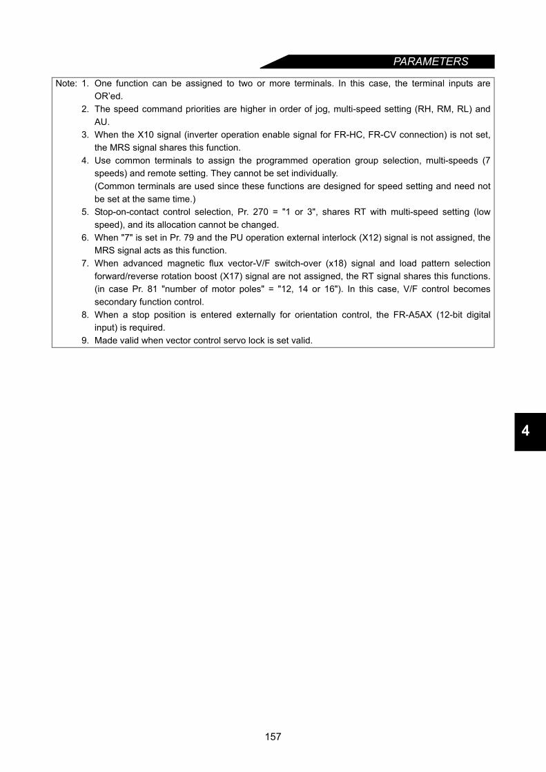
PARAMETERS
4
Note: 1. One function can be assigned to two or more terminals. In this case, the terminal inputs areOR’ed.
2. The speed command priorities are higher in order of jog, multi-speed setting (RH, RM, RL) andAU.
3. When the X10 signal (inverter operation enable signal for FR-HC, FR-CV connection) is not set,the MRS signal shares this function.
4. Use common terminals to assign the programmed operation group selection, multi-speeds (7speeds) and remote setting. They cannot be set individually.(Common terminals are used since these functions are designed for speed setting and need notbe set at the same time.)
5. Stop-on-contact control selection, Pr. 270 = "1 or 3", shares RT with multi-speed setting (lowspeed), and its allocation cannot be changed.
6. When "7" is set in Pr. 79 and the PU operation external interlock (X12) signal is not assigned, theMRS signal acts as this function.
7. When advanced magnetic flux vector-V/F switch-over (x18) signal and load pattern selectionforward/reverse rotation boost (X17) signal are not assigned, the RT signal shares this functions.(in case Pr. 81 "number of motor poles" = "12, 14 or 16"). In this case, V/F control becomessecondary function control.
8. When a stop position is entered externally for orientation control, the FR-A5AX (12-bit digitalinput) is required.
9. Made valid when vector control servo lock is set valid.
157

PARAMETERS
4.2.52 Output terminal function selection (Pr. 190 to Pr. 195)Pr. 190 "RUN terminal function selection"Pr. 191 "SU terminal function selection"Pr. 192 "IPF terminal function selection"Pr. 193 "OL terminal function selection"Pr. 194 "FU terminal function selection"Pr. 195 "A, B, C terminal function selection"You can change the functions of the open collector and contact output terminals.
<Setting>Refer to the following table and set the parameters:
Parameter Number
Terminal Symbol Factory Setting Factory-Set
Terminal Function Setting Range
190 RUN 0 Inverter running
0 to 199, 9999
191 SU 1 Up to frequency
192 IPF 2 Instantaneous power failure/undervoltage
193 OL 3 Overload alarm
194 FU 4 Output frequency detection
195 A, B, C 99 Alarm output
SettingSignal Name Function Operation Related
parameterPositive logic
Negative logic
0 100 RUN Inverter running Output during operation when the inverter output frequency rises to or above the starting frequency.
1 101 SU Up to frequency Refer to Pr. 41 "up-to-frequency sensitivity". (Note 2) Pr. 41
2 102 IPF Instantaneous power failure or undervoltage
Output when an instantaneous power failure or undervoltage occurs.
3 103 OL Overload alarm Output while stall prevention function is activated.Pr. 22, Pr. 23, Pr. 66, Pr. 148, Pr. 149, Pr. 154
4 104 FU Output frequency detection Refer to Pr. 42, Pr. 43 (output frequency detection). Pr. 42, Pr. 43
5 105 FU2 Second output frequency detection
Refer to Pr. 50 (second output frequency detection). Pr. 50
6 106 FU3 Third output frequency detection
Refer to Pr. 116 (third output frequency detection). Pr. 116
7 107 RBP Regenerative brake pre-alarm Output when 85% of the regenerative brake duty set in Pr. 70 is reached. Pr. 70
8 108 THP Electronic overcurrent protection pre-alarm
Output when the cumulative electronic overcurrent protection value reaches 85% of the preset level.
Pr. 9
9 109 PRG Programmed mode Output in the programmed mode. (Note 3) Pr. 79, Pr. 200 to Pr. 231
10 110 PU PU operation mode Output when the PU operation mode is selected.
11 111 RY Inverter operation ready Output when the inverter can be started by switching the start signal on or while it is running.
12 112 Y12 Output current detection Refer to Pr. 150 and Pr. 151 (output current detection). Pr. 150, Pr. 151
13 113 Y13 Zero current detection Refer to Pr. 152 and Pr. 153 (zero current detection). Pr. 152, Pr. 153
14 114 FDN PID lower limit
Refer to Pr. 128 to Pr. 134 (PID control). Pr. 128 to Pr. 134
15 115 FUP PID upper limit
16 116 RL PID forward-reverse rotation output
158
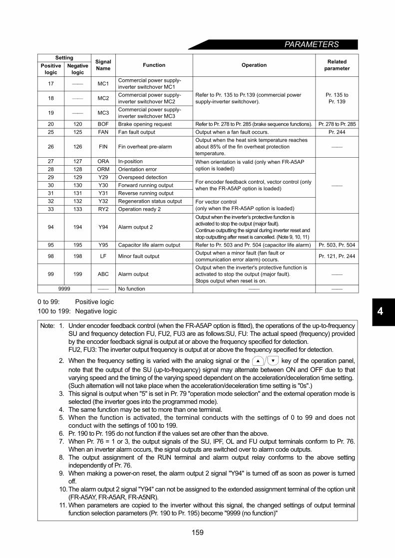
PARAMETERS
4
0 to 99: Positive logic100 to 199: Negative logic17 MC1 Commercial power supply-inverter switchover MC1
Refer to Pr. 135 to Pr.139 (commercial power supply-inverter switchover).
Pr. 135 toPr. 13918 MC2 Commercial power supply-
inverter switchover MC2
19 MC3 Commercial power supply-inverter switchover MC3
20 120 BOF Brake opening request Refer to Pr. 278 to Pr. 285 (brake sequence functions). Pr. 278 to Pr. 28525 125 FAN Fan fault output Output when a fan fault occurs. Pr. 244
26 126 FIN Fin overheat pre-alarmOutput when the heat sink temperature reaches about 85% of the fin overheat protection temperature.
27 127 ORA In-position When orientation is valid (only when FR-A5AP option is loaded)
28 128 ORM Orientation error29 129 Y29 Overspeed detection
For encoder feedback control, vector control (only when the FR-A5AP option is loaded)30 130 Y30 Forward running output
31 131 Y31 Reverse running output32 132 Y32 Regeneration status output For vector control
(only when the FR-A5AP option is loaded)33 133 RY2 Operation ready 2
94 194 Y94 Alarm output 2
Output when the inverter’s protective function is activated to stop the output (major fault).Continue outputting the signal during inverter reset and stop outputting after reset is cancelled. (Note 9, 10, 11)
95 195 Y95 Capacitor life alarm output Refer to Pr. 503 and Pr. 504 (capacitor life alarm) Pr. 503, Pr. 504
98 198 LF Minor fault output Output when a minor fault (fan fault or communication error alarm) occurs. Pr. 121, Pr. 244
99 199 ABC Alarm outputOutput when the inverter's protective function is activated to stop the output (major fault).Stops output when reset is on.
9999 No function
Note: 1. Under encoder feedback control (when the FR-A5AP option is fitted), the operations of the up-to-frequencySU and frequency detection FU, FU2, FU3 are as follows:SU, FU: The actual speed (frequency) providedby the encoder feedback signal is output at or above the frequency specified for detection.FU2, FU3: The inverter output frequency is output at or above the frequency specified for detection.
2. When the frequency setting is varied with the analog signal or the key of the operation panel,note that the output of the SU (up-to-frequency) signal may alternate between ON and OFF due to thatvarying speed and the timing of the varying speed dependent on the acceleration/deceleration time setting.(Such alternation will not take place when the acceleration/deceleration time setting is "0s".)
3. This signal is output when "5" is set in Pr. 79 "operation mode selection" and the external operation mode isselected (the inverter goes into the programmed mode).
4. The same function may be set to more than one terminal.5. When the function is activated, the terminal conducts with the settings of 0 to 99 and does not
conduct with the settings of 100 to 199.6. Pr. 190 to Pr. 195 do not function if the values set are other than the above.7. When Pr. 76 = 1 or 3, the output signals of the SU, IPF, OL and FU output terminals conform to Pr. 76.
When an inverter alarm occurs, the signal outputs are switched over to alarm code outputs.8. The output assignment of the RUN terminal and alarm output relay conforms to the above setting
independently of Pr. 76.9. When making a power-on reset, the alarm output 2 signal "Y94" is turned off as soon as power is turned
off.10.The alarm output 2 signal "Y94" can not be assigned to the extended assignment terminal of the option unit
(FR-A5AY, FR-A5AR, FR-A5NR).11. When parameters are copied to the inverter without this signal, the changed settings of output terminal
function selection parameters (Pr. 190 to Pr. 195) become "9999 (no function)"
SettingSignal Name Function Operation Related
parameterPositive logic
Negative logic
159
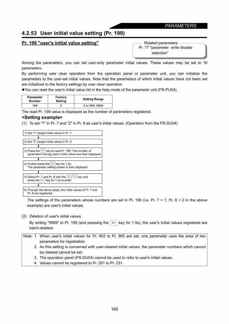
160
PARAMETERS4.2.53 User initial value setting (Pr. 199)
Pr. 199 "user's initial value setting"
Among the parameters, you can set user-only parameter initial values. These values may be set to 16parameters.By performing user clear operation from the operation panel or parameter unit, you can initialize theparameters to the user-set initial values. Note that the parameters of which initial values have not been setare initialized to the factory settings by user clear operation.You can read the user's initial value list in the help mode of the parameter unit (FR-PU04).
The read Pr. 199 value is displayed as the number of parameters registered.<Setting example>(1) To set "1" in Pr. 7 and "2" in Pr. 8 as user's initial values. (Operation from the FR-DU04)
The settings of the parameters whose numbers are set in Pr. 199 (i.e. Pr. 7 = 1, Pr. 8 = 2 in the aboveexample) are user's initial values.
(2) Deletion of user's initial values
By writing "9999" to Pr. 199 (and pressing the key for 1.5s), the user's initial values registered arebatch-deleted.
Parameter Number
FactorySetting Setting Range
199 0 0 to 999, 9999
Note: 1. When user's initial values for Pr. 902 to Pr. 905 are set, one parameter uses the area of twoparameters for registration.
2. As this setting is concerned with user-cleared initial values, the parameter numbers which cannotbe cleared cannot be set.
3. The operation panel (FR-DU04) cannot be used to refer to user's initial values.4. Values cannot be registered to Pr. 201 to Pr. 231.
Related parametersPr. 77 "parameter write disable
selection"
6) Through the above steps, the initial values of Pr. 7 and Pr. 8 are registered.
1) Set "1" (target initial value) in Pr. 7.
2) Set "2" (target initial value) in Pr. 8.
3) Press the key to read Pr. 199. The number of parameters having user's initial values are then displayed.
4) Further press the key for 1.5s. The parameter setting screen is then displayed.
5) Select Pr. 7 and Pr. 8 with the key and press the key for 1.5s to enter.
SET
SET
SET
SET
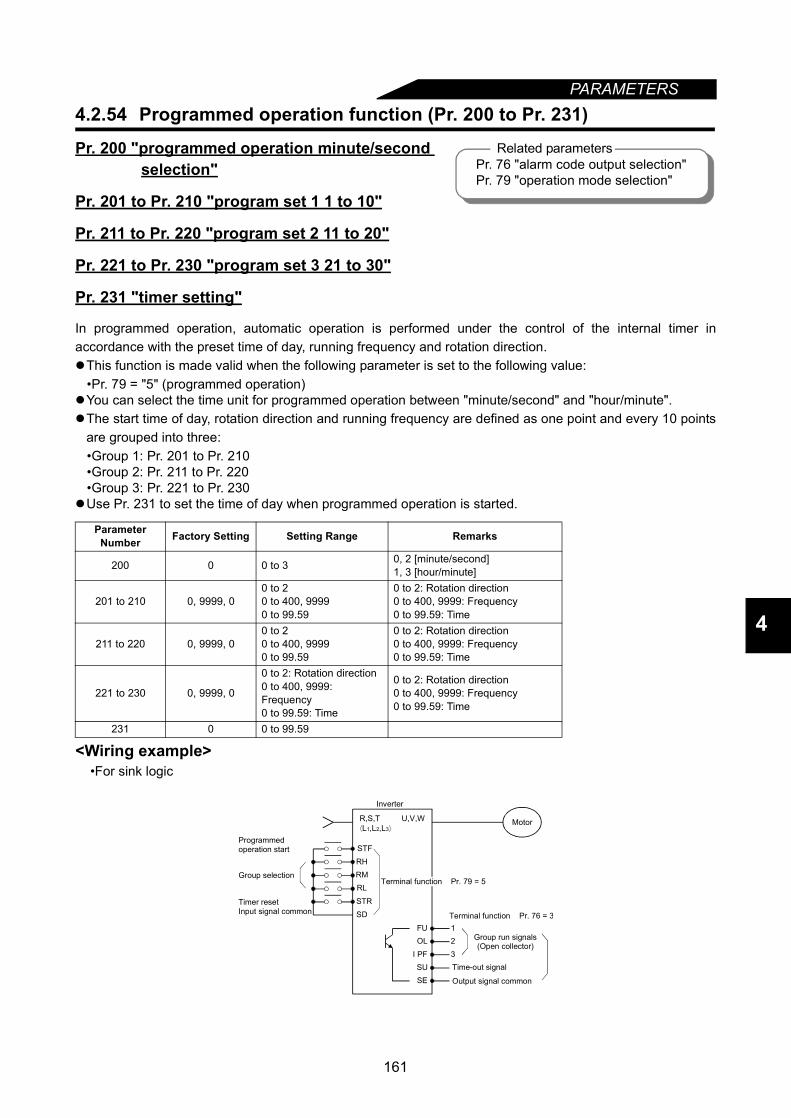
PARAMETERS
4
4.2.54 Programmed operation function (Pr. 200 to Pr. 231)
Pr. 200 "programmed operation minute/second selection"
Pr. 201 to Pr. 210 "program set 1 1 to 10"
Pr. 211 to Pr. 220 "program set 2 11 to 20"
Pr. 221 to Pr. 230 "program set 3 21 to 30"
Pr. 231 "timer setting"
In programmed operation, automatic operation is performed under the control of the internal timer inaccordance with the preset time of day, running frequency and rotation direction.This function is made valid when the following parameter is set to the following value:
•Pr. 79 = "5" (programmed operation)You can select the time unit for programmed operation between "minute/second" and "hour/minute". The start time of day, rotation direction and running frequency are defined as one point and every 10 points
are grouped into three:•Group 1: Pr. 201 to Pr. 210•Group 2: Pr. 211 to Pr. 220•Group 3: Pr. 221 to Pr. 230
Use Pr. 231 to set the time of day when programmed operation is started.
<Wiring example>•For sink logic
Parameter Number Factory Setting Setting Range Remarks
200 0 0 to 3 0, 2 [minute/second]1, 3 [hour/minute]
201 to 210 0, 9999, 00 to 20 to 400, 99990 to 99.59
0 to 2: Rotation direction0 to 400, 9999: Frequency0 to 99.59: Time
211 to 220 0, 9999, 00 to 20 to 400, 99990 to 99.59
0 to 2: Rotation direction0 to 400, 9999: Frequency0 to 99.59: Time
221 to 230 0, 9999, 0
0 to 2: Rotation direction0 to 400, 9999: Frequency0 to 99.59: Time
0 to 2: Rotation direction0 to 400, 9999: Frequency0 to 99.59: Time
231 0 0 to 99.59
Related parametersPr. 76 "alarm code output selection"Pr. 79 "operation mode selection"
STF
RHRMRL
STR
SD
FUOL
PFSUSE
I
1 2
3
U,V,W
Output signal common
Programmed operation start
Group selection
Timer resetInput signal common
Inverter
Motor
Terminal function Pr. 79 = 5
Terminal function Pr. 76 = 3
Group run signals(Open collector)
Time-out signal
R,S,T⟨L1,L2,L3⟩
161

PARAMETERS
<Setting>(1) Set the time unit for programmed operation in Pr. 200. Select either of "minute/second" and "hour/
minute".
(2) The inverter has an internal timer (RAM). When the reference time of day is set in Pr. 231, programmedoperation is started at this time of day.
1) Setting rangeThe time unit depends on the Pr. 200 setting.
2) Resetting the reference time of dayThe reference time of day is cleared by switching on the timer reset signal (STR) or by resetting theinverter. Note that the reference time-of-day value set in Pr. 231 is also reset to "0".
(3) Program settingThe rotation direction, running frequency and start time of day are defined as one point and every 10points are grouped into three. The values can be set by using Pr. 201 to Pr. 231.
Setting Description0 Minute/second unit (voltage monitor)1 Hour/minute unit (voltage monitor)2 Minute/second unit (reference time of day monitor)3 Hour/minute unit (reference time of day monitor)
Note: 1. When "2" or "3" is set in Pr. 200, the reference time-of-day monitor screen is displayedinstead of the voltage monitor screen.
2. Note that when the Pr. 200 setting is changed, the units for Pr. 201 to Pr. 231 setting willchange.
Pr. 200 Setting Pr. 231 Setting Range Pr. 200 Setting Pr. 231 Setting Range0 Maximum 99 minutes 59 s 2 Maximum 99 minutes 59 s1 Maximum 99 hours 59 minutes 3 Maximum 99 hours 59 minutes
Note: The reference time-of-day timer returns to "0" when both the start signal and group selectsignal are entered. Set the reference time of day in Pr. 231 when both signals are on.
Parameter Number Name Setting Range Factory
Setting Remarks
201 to 230Programmed operation minute/second selection
0 to 2 0 Rotation direction setting0: Stop, 1: Forward rotation, 2: Reverse rotation
0 to 400Hz 9999 Frequency setting0 to 99:59 0 Time of day setting
No.1 Pr. 201 2 Pr. 202 3 Pr. 203 4 Pr. 204
10 Pr. 210
No.11 Pr. 211
20 Pr. 220
No.21 Pr. 221
30 Pr. 230
Group 3
Setting Point Rotation Direction, Frequency, Start Time of Day
Group 1
Group 2
162
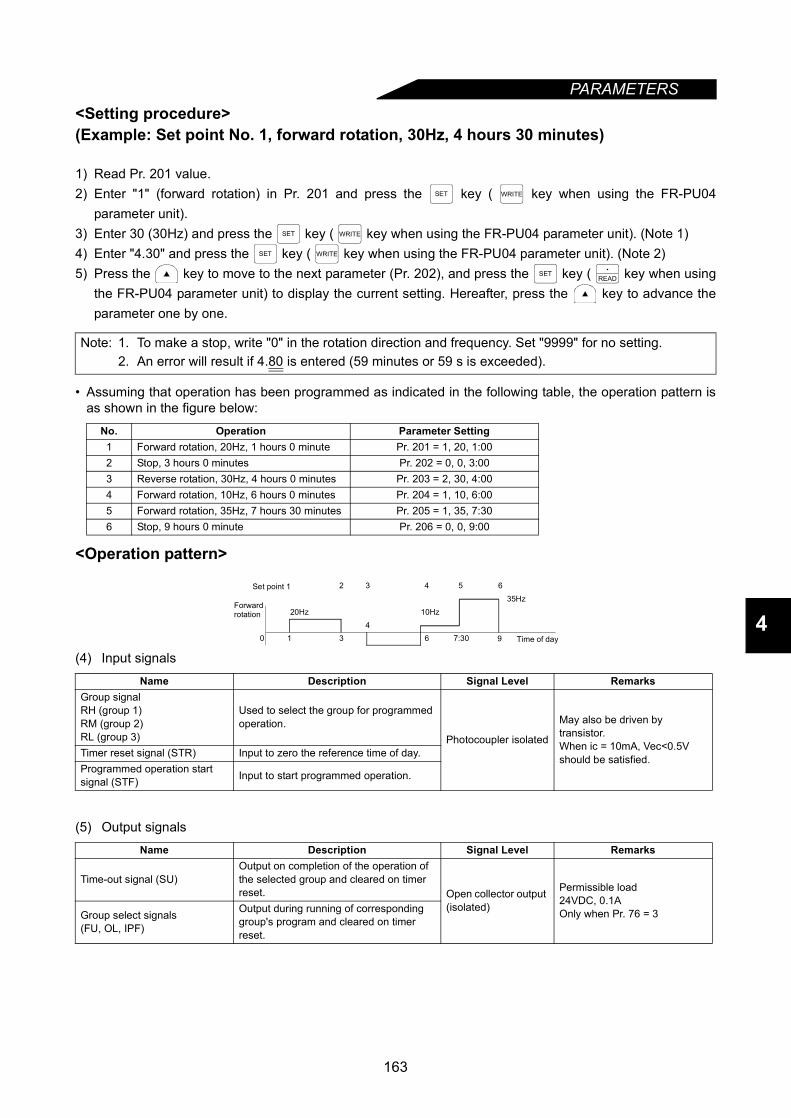
PARAMETERS
4
<Setting procedure>(Example: Set point No. 1, forward rotation, 30Hz, 4 hours 30 minutes)
1) Read Pr. 201 value.2) Enter "1" (forward rotation) in Pr. 201 and press the key ( key when using the FR-PU04
parameter unit).3) Enter 30 (30Hz) and press the key ( key when using the FR-PU04 parameter unit). (Note 1)4) Enter "4.30" and press the key ( key when using the FR-PU04 parameter unit). (Note 2)5) Press the key to move to the next parameter (Pr. 202), and press the key ( key when using
the FR-PU04 parameter unit) to display the current setting. Hereafter, press the key to advance theparameter one by one.
• Assuming that operation has been programmed as indicated in the following table, the operation pattern isas shown in the figure below:
<Operation pattern>
(4) Input signals
(5) Output signals
Note: 1. To make a stop, write "0" in the rotation direction and frequency. Set "9999" for no setting.2. An error will result if 4.80 is entered (59 minutes or 59 s is exceeded).
No. Operation Parameter Setting1 Forward rotation, 20Hz, 1 hours 0 minute Pr. 201 = 1, 20, 1:002 Stop, 3 hours 0 minutes Pr. 202 = 0, 0, 3:003 Reverse rotation, 30Hz, 4 hours 0 minutes Pr. 203 = 2, 30, 4:004 Forward rotation, 10Hz, 6 hours 0 minutes Pr. 204 = 1, 10, 6:005 Forward rotation, 35Hz, 7 hours 30 minutes Pr. 205 = 1, 35, 7:306 Stop, 9 hours 0 minute Pr. 206 = 0, 0, 9:00
Name Description Signal Level RemarksGroup signalRH (group 1)RM (group 2)RL (group 3)
Used to select the group for programmed operation.
Photocoupler isolated
May also be driven by transistor.When ic = 10mA, Vec<0.5V should be satisfied.Timer reset signal (STR) Input to zero the reference time of day.
Programmed operation start signal (STF) Input to start programmed operation.
Name Description Signal Level Remarks
Time-out signal (SU)Output on completion of the operation of the selected group and cleared on timer reset. Open collector output
(isolated)
Permissible load24VDC, 0.1AOnly when Pr. 76 = 3Group select signals
(FU, OL, IPF)
Output during running of corresponding group's program and cleared on timer reset.
SET WRITE
SET WRITE
SET WRITE
SETREAD
20Hz
0 1 34
6 9
10Hz
32 4 5 6
7:30
35Hz
Time of day
Set point 1
Forwardrotation
163

PARAMETERS
(6) Operation1) Ordinary operationAfter completion of all preparations and settings, turn on the desired group select signal (any of RH(group 1), RM (group 2) and RL (group 3)), then turn on the start signal (STF). This causes the internaltimer (reference time of day) to be reset automatically and the operation of that group to be performedin sequence in accordance with the settings. When the operation of the group ends, a signal is outputfrom the time-out output terminal. (The open collector signal of SU is turned on.)Note: Use the programmed operation function with "5" set in Pr. 79. Programmed operation will not be
performed if any of the group select signals is switched on during PU operation or data linkoperation.
2) Multi-group select operationWhen two or more groups are selected at the same time, the operations of the selected groups areexecuted in sequence of group 1, group 2 and group 3.For example, if group 1 and group 2 have been selected, the operation of group 1 is first carried out,and after that operation ends, the reference time of day is reset, the operation of group 2 is started, andthe time-out signal (SU) is output after the operation of group 2 ends.
(7) To repeat the operation of the same group, reset the timer using the time-out signal as shown below.1) To repeat the operation of only group 1 2) To repeat the operation of groups 1 and 2
Note: 1. If the inverter power is switched off, then on (including an instantaneous power failure) during theexecution of the programmed operation, the internal timer is reset and the inverter does notrestart if the power is restored.To resume the operation, turn the programmed operation start signal (STF) off, then on. (At thistime, when it is required to set the reference time of day, switch the start signal on before setting.)
2. When the inverter is wired for programmed operation specifications, the following signals areinvalid:AU, STOP, 2, 4, 1, JOG
3. During programmed operation, the inverter cannot be operated in any other mode. When theprogrammed operation start signal (STF) and timer reset signal (STR) are on, the operation modecannot be switched between PU operation and external operation.).
Pr. 232 to Pr. 239 Refer to Pr. 4.Pr. 240 Refer to Pr. 72.
t1 t2 t3 t4 t5 t6
f1f2 f3
f4f5
0 0
Note that the operation is not started if thetimer reset signal (STR) is on.
Start signalSTF
Group 1 RH
Inverter outputfrequency
Time-out signal (SU)
Setting of group 1
t1 t2 t3 t4 t5 t1 t2 t3 t4 t5 t6
f1f2 f3
f4f5
f1f2 f3 f4
0 0 0
0t'1 t'2
t'3t'4 t'5 t'1 t'2 t'3 t'4
t'5
Time-out signal (SU)
Start signalSTF
Group 1 RH
Group 2 RM
Inverter output frequency
Group 1 select signal (FU)
Group 2 select signal (OL)
Setting of group 1 Setting of group 2
STF
STR
SU
SD
SE
(Group 3) RL
Inverter
(Group 1) RH(Group 2) RM
STF
STR
SU
SD
SE
(Group 3) RL
Inverter
(Group 1) RH
(Group 2) RM
164
165
PARAMETERS
4
4.2.55 Cooling fan operation selection (Pr. 244)
Pr. 244 "cooling fan operation selection"
You can control the operation of the cooling fan built in the inverter (200V class... 1.5K or more, 400V class...2.2K or more).
<Setting>
<Reference>In either of the following cases, fan operation is regarded as faulty, [FN] is shown on the operation panel, andthe fan fault (FAN) and light fault (LF) signals are output. Use Pr. 190 to Pr. 195 (output terminal functionselection) to allocate the terminals used to output the FAN and LF signals.
1) Pr. 244 = "0"When the fan comes to a stop with power on.
2) Pr. 244 = "1"When the fan stops during the fan ON command while the inverter is running.
Parameter Number Factory Setting Setting Range
244 0 0,1
Setting Description0 Operated at power on (independently of whether the inverter is running or at a stop).
1Cooling fan on-off control valid(The cooling fan is always on while the inverter is running. During a stop, the inverter status is monitored and the fan switches on-off according to temperature.)
Note: When the terminal functions are changed using Pr. 190 to Pr. 195, the other functions may beaffected. Confirm the functions of the corresponding terminals before making setting.

166
PARAMETERS4.2.56 Stop selection (Pr. 250)
Pr. 250 "stop selection"
Used to select the stopping method (deceleration to a stop or coasting) when the start signal (STF/STR)turns off.
(1) Pr. 250 = "9999"When the start signal switches off, the motor is decelerated to a stop.
(2) Pr. 250 = other than "9999" (Output is shut off after preset time.)The output is shut off when the time set in Pr. 250 has elapsed after the start signal had turned off. Themotor coasts to a stop.
Parameter Number Factory Setting Setting Range
250 9999 0 to 100 s, 9999
Note: 1. The RUN signal turns off when the output stops.2. When the start signal is turned on again during motor coasting, the motor starts at 0Hz.
Related parametersPr. 7 "acceleration time"Pr. 8 "deceleration time"Pr. 44 "second acceleration/deceleration
time"Pr. 45 "second deceleration time"Pr. 110 "third acceleration/deceleration
time"Pr. 111 "third deceleration time"
Time
ON OFF
DC brake
Start signal
Out
put f
requ
ency
(Hz)
Decelerated when start signal switches off.
Deceleration time (time set in Pr. 8, etc.)
OFF
OFF
Start signal
RUN signal
Time
Output is shut off when time set in Pr. 250 haselapsed after start signal had switched off.
Motor coasts to a stop.
Out
put f
requ
ency
(Hz)
167
PARAMETERS
4
4.2.57 Output phase failure protection selection (Pr. 251)
Pr. 251 "output phase failure protection selection"
You can make the output phase failure protection (E.LF) function which stops the inverter output invalid if oneof the three phases (U, V, W) on the inverter's output side (load side) becomes open.
4.2.58 Override bias/gain (Pr. 252, Pr. 253)
Pr. 252 "override bias"
Pr. 253 "override gain"
When override is selected in Pr. 73 "0 to 5V, 0 to 10V selection", the override range can be extended from50%-150% to 0%-200% and set as desired.
Parameter Number
Setting Range
Minimum Setting
IncrementsFactory Setting Description
251 0,1 1 1 0: Without output phase failure protection1: With output phase failure protection
Parameter Number Setting Range Minimum Setting Increments Factory Setting
252 0 to 200% 0.1% 50%253 0 to 200% 0.1% 150%
Related parameters
Pr. 73 "0 - 5V / 0 - 10V selection"
Ove
rrid
e va
lue
(%)
Pr. 252
0V 2.5V(5V)
5V(10V)
0
50
100
150
200
Factory setting(50% to 150%)
Voltage across 2-5
Pr. 253

PARAMETERS
4.2.59 Power failure-time deceleration-to-stop function (Pr. 261 to Pr. 266)Pr. 261"power failure stop selection"
Pr. 262"subtracted frequency at decelerationstart"
Pr. 263"subtraction starting frequency"
Pr. 264"power-failure deceleration time 1"
Pr. 265"power-failure deceleration time 2"
Pr. 266"power-failure deceleration time switch-over frequency"
When an instantaneous power failure or undervoltage occurs, the inverter can be decelerated to a stop.Remove the jumpers from across terminals R-R1 <L1-L11> and terminals S-S1 <L2-L21> and connect
terminal R1 <L11> to terminal P <+> and terminal S1 <L21> to terminal N <->.
<Setting>
Parameter Number Factory Setting Setting Range
261 0 0, 1262 3Hz 0 to 20Hz263 60Hz <50Hz> 0 to 120Hz, 9999264 5 s 0 to 3600/0 to 360 s265 9999 0 to 3600/0 to 360 s, 9999266 60Hz <50Hz> 0 to 400Hz
Parameter Number Setting Description
2610 Coasting to stop
When undervoltage or power failure occurs, the inverter output is shut off.1 When undervoltage or power failure occurs, the inverter is decelerated to a stop.
262 0 to 20HzNormally, operation can be performed with the factory setting unchanged. The frequency can be adjusted within the range 0 to 20Hz according to the load specifications (moment of inertia, torque).
2630 to 120Hz
If the output frequency at occurrence of undervoltage or power failure is equal to or greaterthan the frequency set in Pr. 263, deceleration starts at the value found by subtracting thefrequency set in Pr. 262 from the output frequency at that time. If the output frequency atoccurrence of undervoltage or power failure is less than the frequency set in Pr. 263, theinverter is decelerated to a stop, starting at the output frequency at that time.
9999 The inverter is decelerated to a stop, starting at the value found by subtracting the frequency set in Pr. 262 from the output frequency at occurrence of undervoltage or power failure.
264Pr. 21 = 0 0 to 3600 s Set a deceleration slope down to the frequency set in Pr. 266. Set the slope in terms of time
required for deceleration from the frequency set in Pr. 20 to 0Hz.Pr. 21 = 1 0 to 360 s
265Pr. 21 = 0 0 to 3600 s Set a deceleration slope below the frequency set in Pr. 266. Set the slope in terms of time
required for deceleration from the frequency set in Pr. 20 to 0Hz.Pr. 21 = 1 0 to 360 s9999 Same slope as in Pr. 264
266 0 to 400Hz Set the frequency at which the deceleration slope is is switched from the Pr. 264 setting to the Pr. 265 setting.
Related parametersPr. 12 "DC injection brake voltage" Pr. 20 "acceleration/deceleration
reference frequency"
Pr.262Pr.264
Pr.265
Pr.266
Time
Power supply
Out
put f
requ
ency
(Hz)
Switch-over frequency
Subtracted frequencyPower-failure deceleration time 1
Power-failure deceleration time 2
168
PARAMETERS
4
4.2.60 Stop-on-contact, load torque high-speed frequency selection (Pr. 270)
Pr. 270 "stop-on-contact/load torquehigh-speed control selection"
To ensure accurate positioning at the upper limit, etc. of a lift, stop-on-contact control causes a mechanicalbrake to be closed while the motor is developing a holding torque to keep the load in contact with amechanical stopper, etc.This function suppresses vibration which is liable to occur when the load is stopped upon contact in verticalmotion applications, ensuring steady precise positioning.
Load torque high-speed frequency control automatically sets the maximum operating frequency according tothe load.Specifically, the weight of the load is determined after a start by the average current at a given time; whenthe load is light, the preset frequency can be increased for operation.When the load is light, speed can be automatically increased in a sky parking lot, for example, to reduceincoming and outgoing times.
Using Pr. 270, select stop-on-contact control and/or high-speed frequency control (control whichautomatically switches between high- and middle-speed operations according to load torque).•When stop-on-contact control is selected, select advanced magnetic flux vector control. For functiondetails, refer to Pr. 275 and Pr. 276.
•For function details of load torque high-speed frequency control, refer to Pr. 271 to Pr. 274.
Note: 1. This function is invalid when the automatic restart after instantaneous power failure function isset.
2. If (output frequency at occurrence of undervoltage or power failure) minus (frequency set in Pr.263) is negative, the calculation result is regarded as 0Hz.
3. The power failure stop function is not activated during a stop or error.4. If power is restored during deceleration, the inverter is kept decelerating to a stop.
To restart, switch off the start signal once, then switch it on again.5. When the high power factor converter is used (Pr. 30 = 2), this function is made invalid
CAUTION
If power-failure deceleration operation is set, some loads may cause the inverter to trip and the motor to coast. If enough regenerative energy is not given by the motor, the motor will coast.
Parameter Number
Factory Setting Setting Range Description
270 0
0 Without stop-on-contact control and load torque high-speed frequency control1 Stop-on-contact control2 Load torque high-speed frequency control3 Stop-on-contact control and load torque high-speed frequency control
Pr. 271 "high-speed setting maximum current"Pr. 272 "mid-speed setting minimum current"Pr. 273 "current averaging range"Pr. 274 "current averaging filter constant"Pr. 275 "stop-on-contact excitation
current low-speed multiplying factor"Pr. 276 "stop-on-contact PWM carrier frequency"
Related parameters
169
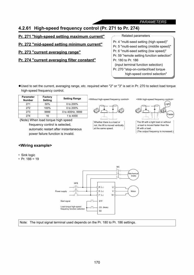
PARAMETERS
4.2.61 High-speed frequency control (Pr. 271 to Pr. 274)Pr. 271 "high-speed setting maximum current"
Pr. 272 "mid-speed setting minimum current"
Pr. 273 "current averaging range"
Pr. 274 "current averaging filter constant"
Used to set the current, averaging range, etc. required when "2" or "3" is set in Pr. 270 to select load torquehigh-speed frequency control.
<Wiring example>
• Sink logic• Pr. 186 = 19
Parameter Number
FactorySetting Setting Range
271 50% 0 to 200%272 100% 0 to 200%273 9999 0 to 400Hz, 9999274 16 1 to 4000
(Note) When load torque high speed frequency control is selected, automatic restart after instantaneous power failure function is invalid.
Note: The input signal terminal used depends on the Pr. 180 to Pr. 186 settings.
Related parameters
Pr. 4 "multi-seed setting (high speed)"Pr. 5 "multi-seed setting (middle speed)"Pr. 6 "multi-seed setting (low speed)"Pr. 59 "remote setting function selection"Pr. 180 to Pr. 186 (input terminal function selection)Pr. 270 "stop-on-contact/load torque
high-speed control selection"
The lift with a light load or without a load is moved faster than thelift with a load.(The output frequency is increased.)
<With high-speed frequency control><Without high-speed frequency control>
Whether there is a load ornot, the lift is moved verticallyat the same speed.
Light
Faster
U
V
W
MC
STF
SD
NFB
MotorPower supply
Start signal
Load torque high-speed frequency function selection
CS (Note)
Mechanical brake
R ⟨L1⟩
S ⟨L2⟩
T ⟨L3⟩
170
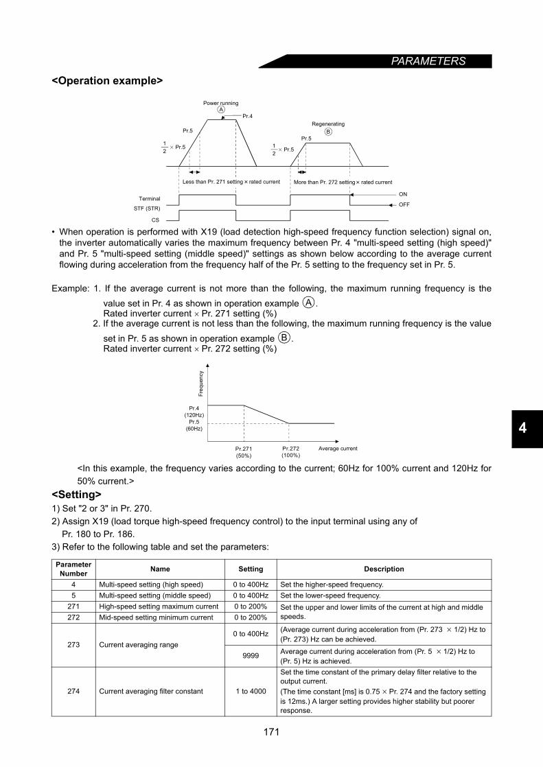
PARAMETERS
4
<Operation example>
• When operation is performed with X19 (load detection high-speed frequency function selection) signal on,the inverter automatically varies the maximum frequency between Pr. 4 "multi-speed setting (high speed)"and Pr. 5 "multi-speed setting (middle speed)" settings as shown below according to the average currentflowing during acceleration from the frequency half of the Pr. 5 setting to the frequency set in Pr. 5.
Example: 1. If the average current is not more than the following, the maximum running frequency is thevalue set in Pr. 4 as shown in operation example .Rated inverter current × Pr. 271 setting (%)
2. If the average current is not less than the following, the maximum running frequency is the valueset in Pr. 5 as shown in operation example .Rated inverter current × Pr. 272 setting (%)
<In this example, the frequency varies according to the current; 60Hz for 100% current and 120Hz for50% current.>
<Setting>1) Set "2 or 3" in Pr. 270.2) Assign X19 (load torque high-speed frequency control) to the input terminal using any of
Pr. 180 to Pr. 186.3) Refer to the following table and set the parameters:
Parameter Number Name Setting Description
4 Multi-speed setting (high speed) 0 to 400Hz Set the higher-speed frequency.5 Multi-speed setting (middle speed) 0 to 400Hz Set the lower-speed frequency.
271 High-speed setting maximum current 0 to 200% Set the upper and lower limits of the current at high and middle speeds.272 Mid-speed setting minimum current 0 to 200%
273 Current averaging range0 to 400Hz (Average current during acceleration from (Pr. 273 × 1/2) Hz to
(Pr. 273) Hz can be achieved.
9999 Average current during acceleration from (Pr. 5 × 1/2) Hz to (Pr. 5) Hz is achieved.
274 Current averaging filter constant 1 to 4000
Set the time constant of the primary delay filter relative to the output current.(The time constant [ms] is 0.75 × Pr. 274 and the factory setting is 12ms.) A larger setting provides higher stability but poorer response.
CS
STF (STR)OFF
ON
Pr.5
Pr.4
Pr.5
A
× Pr.512 × Pr.5
12
B
Terminal
Less than Pr. 271 setting rated current More than Pr. 272 setting rated current
Power running
Regenerating
B
Pr.4(120Hz)
Pr.5(60Hz)
Pr.271(50%)
Pr.272(100%)
Average current
Freq
uenc
y
171
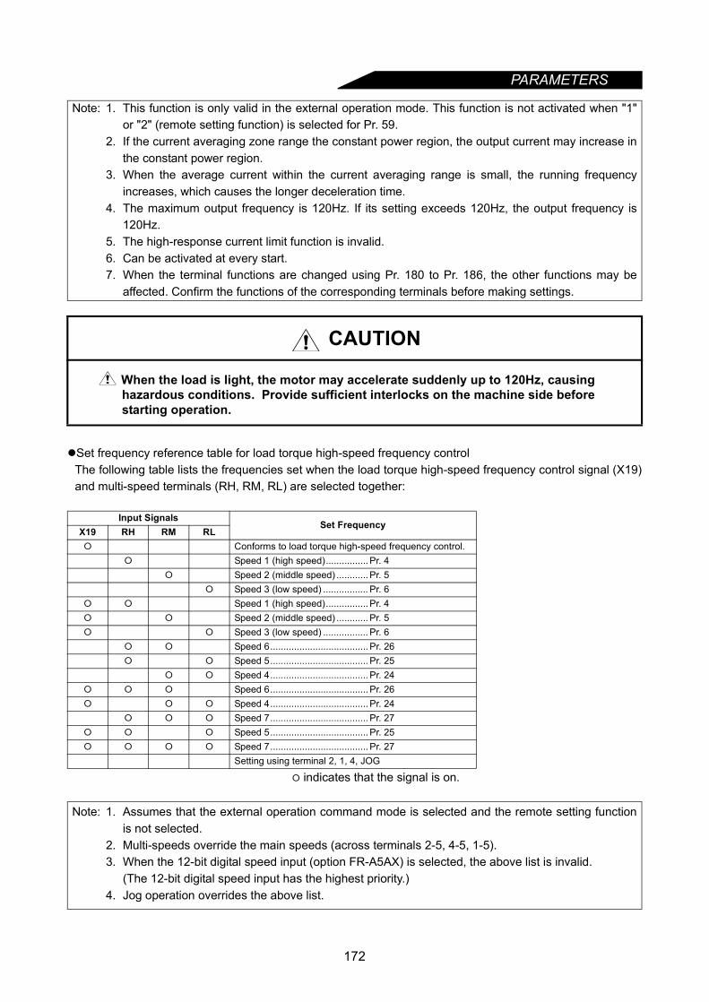
PARAMETERS
Set frequency reference table for load torque high-speed frequency controlThe following table lists the frequencies set when the load torque high-speed frequency control signal (X19)and multi-speed terminals (RH, RM, RL) are selected together:
indicates that the signal is on.
Note: 1. This function is only valid in the external operation mode. This function is not activated when "1"or "2" (remote setting function) is selected for Pr. 59.
2. If the current averaging zone range the constant power region, the output current may increase inthe constant power region.
3. When the average current within the current averaging range is small, the running frequencyincreases, which causes the longer deceleration time.
4. The maximum output frequency is 120Hz. If its setting exceeds 120Hz, the output frequency is120Hz.
5. The high-response current limit function is invalid.6. Can be activated at every start.7. When the terminal functions are changed using Pr. 180 to Pr. 186, the other functions may be
affected. Confirm the functions of the corresponding terminals before making settings.
CAUTION
When the load is light, the motor may accelerate suddenly up to 120Hz, causing hazardous conditions. Provide sufficient interlocks on the machine side before starting operation.
Input SignalsSet Frequency
X19 RH RM RL Conforms to load torque high-speed frequency control.
Speed 1 (high speed)................ Pr. 4 Speed 2 (middle speed) ............ Pr. 5
Speed 3 (low speed) ................. Pr. 6 Speed 1 (high speed)................ Pr. 4 Speed 2 (middle speed) ............ Pr. 5 Speed 3 (low speed) ................. Pr. 6
Speed 6..................................... Pr. 26 Speed 5..................................... Pr. 25
Speed 4..................................... Pr. 24 Speed 6..................................... Pr. 26 Speed 4..................................... Pr. 24
Speed 7..................................... Pr. 27 Speed 5..................................... Pr. 25 Speed 7..................................... Pr. 27
Setting using terminal 2, 1, 4, JOG
Note: 1. Assumes that the external operation command mode is selected and the remote setting functionis not selected.
2. Multi-speeds override the main speeds (across terminals 2-5, 4-5, 1-5).3. When the 12-bit digital speed input (option FR-A5AX) is selected, the above list is invalid.
(The 12-bit digital speed input has the highest priority.)4. Jog operation overrides the above list.
172
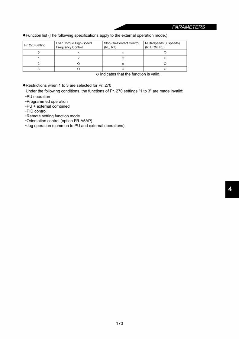
PARAMETERS
4
Function list (The following specifications apply to the external operation mode.)
Indicates that the function is valid.
Restrictions when 1 to 3 are selected for Pr. 270Under the following conditions, the functions of Pr. 270 settings "1 to 3" are made invalid:•PU operation•Programmed operation•PU + external combined•PID control•Remote setting function mode•Orientation control (option FR-A5AP)•Jog operation (common to PU and external operations)
Pr. 270 Setting Load Torque High-SpeedFrequency Control
Stop-On-Contact Control(RL, RT)
Multi-Speeds (7 speeds)(RH, RM, RL)
0 × ×
1 ×
2 ×
3
173

PARAMETERS
4.2.62 Stop-on-contact control function (Pr. 275, Pr. 276)Pr. 275 "stop-on-contact excitation currentlow-speed multiplying factor"
Pr. 276 "stop-on-contact PWM carrierfrequency"
Set "1 or 3" (stop-on-contact control) in Pr. 270. Also advanced magnetic flux vector control must beselected.
<Wiring and operation examples>• Sink logic
When both the RT and RL terminals are switched on, the inverter enters the stop-on-contact mode, in whichoperation is performed at the frequency set in Pr. 6 "multi-speed setting (low speed)" independently of thepreceding speed.
Parameter Number
FactorySetting Setting Range
270 0 0, 1, 2, 3, 275 9999 0 to 1000%, 9999276 9999 0 to 15, 9999
Note: The input signal terminals used depend on the Pr. 180 to Pr. 186 settings.
Related parametersPr. 4 "multi-seed setting (high speed)"Pr. 5 "multi-seed setting (middle speed)"Pr. 6 "multi-seed setting (low speed)"Pr. 48 "second stall preventionPr. 72 "PWM carrier frequency"
operation current"Pr. 180 to Pr. 186
(input terminal function selection)Pr. 270 "stop-on-contact, load torque
high-speed frequency selection"
Lift
<Without stop-on-contact control> <With stop-on-contact control>
Vibration Complete stop
Lift
NFB
STFRH
RM
RL
RT
SD
U
V
W
MC
MotorPower supply
Stop-on-contact selection 2
Start signalMulti-speed selection 1
Multi-speed selection 2Stop-on-contact selection 1
Mechanicalbrake
R ⟨L1⟩
S ⟨L2⟩
T ⟨L3⟩
(a) (b) (c)
Time
Pr.4
RHONOFF
RMONOFF
RLONOFF
RTONOFF
Pr.5
Pr.6
Output frequency
0
Ordinary mode Stop-on-contact control
Goes into stop-on-contact control mode when both RL and RT switch on.Note: (RL and RT may be switched on in any order with any time difference.) (a) Acceleration time (Pr. 7) (b) Deceleration time (Pr. 8) (c) Second deceleration time (Pr. 44)
174
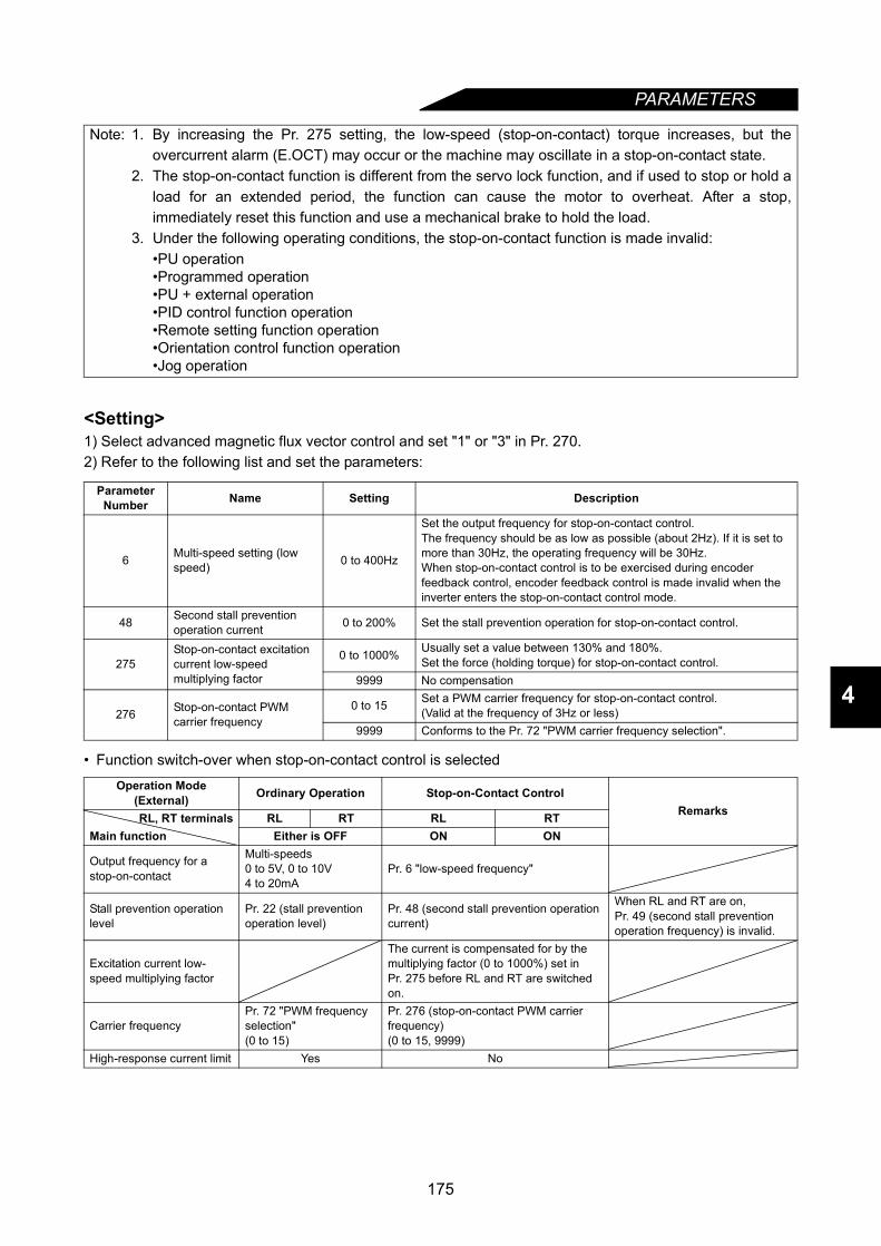
PARAMETERS
4
<Setting>1) Select advanced magnetic flux vector control and set "1" or "3" in Pr. 270.2) Refer to the following list and set the parameters:
• Function switch-over when stop-on-contact control is selected
Note: 1. By increasing the Pr. 275 setting, the low-speed (stop-on-contact) torque increases, but theovercurrent alarm (E.OCT) may occur or the machine may oscillate in a stop-on-contact state.
2. The stop-on-contact function is different from the servo lock function, and if used to stop or hold aload for an extended period, the function can cause the motor to overheat. After a stop,immediately reset this function and use a mechanical brake to hold the load.
3. Under the following operating conditions, the stop-on-contact function is made invalid:•PU operation•Programmed operation•PU + external operation•PID control function operation•Remote setting function operation•Orientation control function operation•Jog operation
Parameter Number Name Setting Description
6 Multi-speed setting (low speed) 0 to 400Hz
Set the output frequency for stop-on-contact control.The frequency should be as low as possible (about 2Hz). If it is set to more than 30Hz, the operating frequency will be 30Hz.When stop-on-contact control is to be exercised during encoder feedback control, encoder feedback control is made invalid when the inverter enters the stop-on-contact control mode.
48 Second stall prevention operation current 0 to 200% Set the stall prevention operation for stop-on-contact control.
275Stop-on-contact excitation current low-speed multiplying factor
0 to 1000% Usually set a value between 130% and 180%.Set the force (holding torque) for stop-on-contact control.
9999 No compensation
276 Stop-on-contact PWM carrier frequency
0 to 15 Set a PWM carrier frequency for stop-on-contact control.(Valid at the frequency of 3Hz or less)
9999 Conforms to the Pr. 72 "PWM carrier frequency selection".
Operation Mode(External) Ordinary Operation Stop-on-Contact Control
RemarksRL, RT terminals RL RT RL RTMain function Either is OFF ON ON
Output frequency for a stop-on-contact
Multi-speeds0 to 5V, 0 to 10V4 to 20mA
Pr. 6 "low-speed frequency"
Stall prevention operation level
Pr. 22 (stall prevention operation level)
Pr. 48 (second stall prevention operation current)
When RL and RT are on, Pr. 49 (second stall prevention operation frequency) is invalid.
Excitation current low-speed multiplying factor
The current is compensated for by the multiplying factor (0 to 1000%) set inPr. 275 before RL and RT are switched on.
Carrier frequencyPr. 72 "PWM frequency selection"(0 to 15)
Pr. 276 (stop-on-contact PWM carrier frequency)(0 to 15, 9999)
High-response current limit Yes No
175
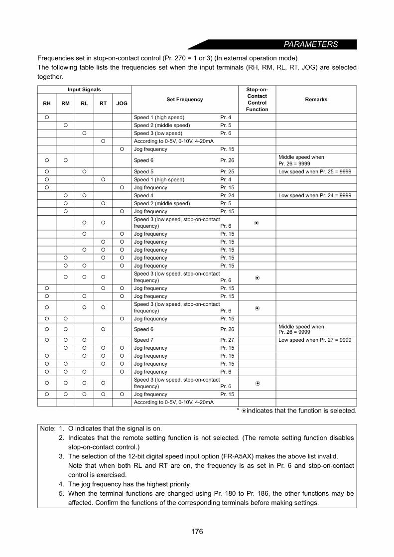
PARAMETERS
Frequencies set in stop-on-contact control (Pr. 270 = 1 or 3) (In external operation mode)The following table lists the frequencies set when the input terminals (RH, RM, RL, RT, JOG) are selectedtogether.
* indicates that the function is selected.
Input Signals
Set Frequency
Stop-on-Contact Control
Function
RemarksRH RM RL RT JOG
Speed 1 (high speed) Pr. 4 Speed 2 (middle speed) Pr. 5
Speed 3 (low speed) Pr. 6 According to 0-5V, 0-10V, 4-20mA
Jog frequency Pr. 15
Speed 6 Pr. 26 Middle speed whenPr. 26 = 9999
Speed 5 Pr. 25 Low speed when Pr. 25 = 9999 Speed 1 (high speed) Pr. 4 Jog frequency Pr. 15
Speed 4 Pr. 24 Low speed when Pr. 24 = 9999 Speed 2 (middle speed) Pr. 5 Jog frequency Pr. 15
Speed 3 (low speed, stop-on-contact frequency) Pr. 6
Jog frequency Pr. 15 Jog frequency Pr. 15
Jog frequency Pr. 15 Jog frequency Pr. 15 Jog frequency Pr. 15
Speed 3 (low speed, stop-on-contact frequency) Pr. 6
Jog frequency Pr. 15 Jog frequency Pr. 15
Speed 3 (low speed, stop-on-contact frequency) Pr. 6
Jog frequency Pr. 15
Speed 6 Pr. 26 Middle speed whenPr. 26 = 9999
Speed 7 Pr. 27 Low speed when Pr. 27 = 9999 Jog frequency Pr. 15
Jog frequency Pr. 15 Jog frequency Pr. 15 Jog frequency Pr. 6
Speed 3 (low speed, stop-on-contact frequency) Pr. 6
Jog frequency Pr. 15According to 0-5V, 0-10V, 4-20mA
Note: 1. O indicates that the signal is on.2. Indicates that the remote setting function is not selected. (The remote setting function disables
stop-on-contact control.)3. The selection of the 12-bit digital speed input option (FR-A5AX) makes the above list invalid.
Note that when both RL and RT are on, the frequency is as set in Pr. 6 and stop-on-contactcontrol is exercised.
4. The jog frequency has the highest priority.5. When the terminal functions are changed using Pr. 180 to Pr. 186, the other functions may be
affected. Confirm the functions of the corresponding terminals before making settings.
176

PARAMETERS
4
4.2.63 Brake sequence function (Pr. 278 to Pr. 285)
Pr. 278 "brake opening frequency"
Pr. 279 "brake opening current"
Pr. 280 "brake opening current detection time"
Pr. 281 "brake operation time at start"
Pr. 282 "brake operation frequency"
Pr. 283 "brake operation time at stop"
Pr. 284 "deceleration detection function selection"
Pr. 285 "overspeed detection frequency"
This function is used to output from the inverter the mechanical brake opening completion signal timingsignal in vertical lift and other applications.This function prevents the load from dropping with gravity at starting due to the operation timing fault of themechanical brake or an overcurrent alarm at a stop, ensuring secure operation.
The mechanical brake opening completion signal may either be entered or not entered into the inverter.This function is only valid when "7" or "8" is set in Pr. 60 to select advanced magnetic flux vector control in
the external operation mode. (With the exception of Pr. 285)
(Note) When the brake sequence function is selected, automatic restart after instantaneous power failurefunction is invalid.
<Wiring example>• Sink logic• Pr. 184 = 15• Pr. 190 = 20
Parameter Number
FactorySetting Setting Range
278 3Hz 0 to 30Hz279 130% 0 to 200%280 0.3 s 0 to 2 s281 0.3 s 0 to 5 s282 6Hz 0 to 30Hz283 0.3 s 0 to 5 s284 0 0, 1285 9999 0 to 30Hz, 9999
Note: 1. The input signal terminal used depends on the Pr. 180 to Pr. 186 settings.2. The output signal terminal used depends on the Pr. 190 to Pr. 195 settings.
Related parametersPr. 60 "intelligent mode selection"Pr. 80 "motor capacity"Pr. 81 "number of motor poles"Pr. 180 to Pr. 186 (input terminal function selection)Pr. 190 to Pr. 195 (output terminal function selection)
Brake opening request signal (BOF signal) *Note the permissible current of the inverter's internal transistor. (24VDC 0.1A)
U
V
W
MC
STF
RH
SD SE
MC MC
24VDC
NFB
Start signal
Multi-speed signal
Brake opening completion signal
(Note 2) RUN
AU (Note 1)
Mechanical brake
Motor
(BRI signal)
Power supply
*
R ⟨L1⟩
S ⟨L2⟩
T ⟨L3⟩
177
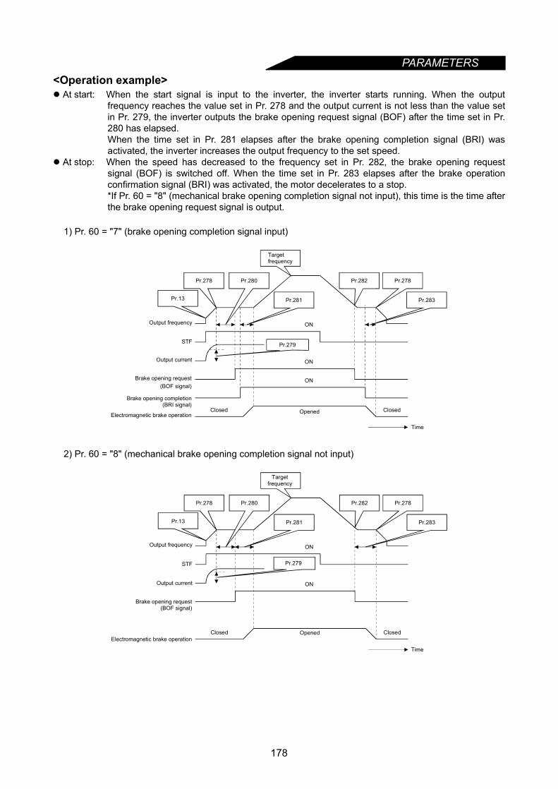
PARAMETERS
<Operation example> At start: When the start signal is input to the inverter, the inverter starts running. When the outputfrequency reaches the value set in Pr. 278 and the output current is not less than the value setin Pr. 279, the inverter outputs the brake opening request signal (BOF) after the time set in Pr.280 has elapsed.When the time set in Pr. 281 elapses after the brake opening completion signal (BRI) wasactivated, the inverter increases the output frequency to the set speed.
At stop: When the speed has decreased to the frequency set in Pr. 282, the brake opening requestsignal (BOF) is switched off. When the time set in Pr. 283 elapses after the brake operationconfirmation signal (BRI) was activated, the motor decelerates to a stop.*If Pr. 60 = "8" (mechanical brake opening completion signal not input), this time is the time afterthe brake opening request signal is output.
1) Pr. 60 = "7" (brake opening completion signal input)
2) Pr. 60 = "8" (mechanical brake opening completion signal not input)
STF
ON
ON
Pr.280Pr.278
Pr.13 Pr.281
Pr.278Pr.282
Pr.283
ON
Pr.279
Time
Targetfrequency
Output frequency
Output current
Brake opening request(BOF signal)
Brake opening completion(BRI signal)
Electromagnetic brake operationClosed Opened Closed
STF
ON
ON
Pr.280Pr.278
Pr.13 Pr.281
Pr.278Pr.282
Pr.283
Pr.279
Time
Targetfrequency
Output frequency
Output current
Brake opening request(BOF signal)
Electromagnetic brake operationClosed Opened Closed
178

PARAMETERS
4
<Setting>(1) Parameter setting
1) Select advanced magnetic flux vector control. (Pr. 80, Pr. 81 ≠ "9999")2) Set "7 or 8" (brake sequence mode) in Pr. 60.
To ensure more complete sequence control, it is recommended to set "7" (brake opening completion signalinput) in Pr. 60. Note that the automatic restart after instantaneous power failure function is not activatedwhen the brake sequence mode is selected.
3) Refer to the following table and set the parameters:
* When vector control is executed with the FR-A5AP, this is replaced with excessive speed deviationdetection frequency. (Refer to the instruction manual of the FR-A5AP for details.)
Note: When using this function, set the acceleration time to 1s or longer.
(2) Explanations of terminals used
The terminals must be allocated using Pr. 180 to Pr. 186 and Pr. 190 to Pr. 195.
Parameter Number Name Setting Description
278 Brake opening frequency 0 to 30Hz Set to the rated slip frequency of the motor + about 1.0Hz.This parameter
may only be set if Pr. 278 ≤ Pr. 282.
279 Brake opening current 0 to 200%Generally, set this parameter to about 50 to 90%. If the setting is too low, the load is liable to drop with gravity at start.Suppose that the rated inverter current is 100%.
280 Brake opening current detection time 0 to 2 s Generally, set this parameter to about 0.1 to 0.3s.
281 Brake operation time at start 0 to 5 s
Pr. 60 = 7: Set the mechanical delay time until the brake is loosened.Pr. 60 = 8: Set the mechanical delay time until the brake is loosened +
about 0.1-0.2s.
282 Brake closing frequency 0 to 30Hz
At this frequency, the brake opening request signal (BOF) is switched off. Generally, set this parameter to the Pr. 278 setting + 3-4Hz.This parameter may only be set if Pr. 282 Pr. 278.
283 Brake operation time at stop 0 to 5 s
Pr. 60 = 7: Set the mechanical delay time until the brake is closed + 0.1s.Pr. 60 = 8: Set the mechanical delay time until the brake is closed + about 0.2 to 0.3 s.
284 Deceleration detection function selection
0 Deceleration is not detected.
1If deceleration is not normal during deceleration operation, the inverter alarm (E.MB2) is provided to shut off the output and switch off the brake opening request signal (BOF).
285 Overspeed detection frequency*
0 to 30HzIf (detected frequency) - (output frequency) > Pr. 285 in the encoder feedback control mode, the inverter alarm (E.MB1) is provided to shut off the output and switch off the brake opening request signal (BOF).
9999 Overspeed is not detected.
Signal Terminals UsedBrake Sequence Mode
Pr. 60 = 7 (with mechanical brake opening completion signal)
Pr. 60 = 8 (without mechanical brake opening completion signal)
BOF According to Pr. 190 to Pr. 195 Brake opening request Brake opening requestBRI According to Pr. 180 to Pr. 186 Brake opening completion signal
Note: 1. The brake opening completion signal (BRI) is a parameter valid when Pr. 60 = 7.2. When the terminal functions are changed using Pr. 180 to 186 and Pr. 190 to Pr. 195, the other
functions may be affected. Confirm the functions of the corresponding terminals before makingsettings.
179
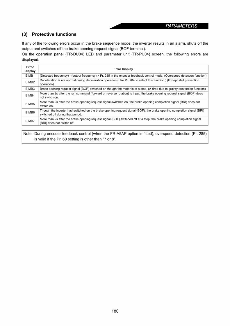
PARAMETERS
(3) Protective functions
If any of the following errors occur in the brake sequence mode, the inverter results in an alarm, shuts off theoutput and switches off the brake opening request signal (BOF terminal).On the operation panel (FR-DU04) LED and parameter unit (FR-PU04) screen, the following errors aredisplayed:
Error Display Error Display
E.MB1 (Detected frequency) - (output frequency) > Pr. 285 in the encoder feedback control mode. (Overspeed detection function)
E.MB2 Deceleration is not normal during deceleration operation (Use Pr. 284 to select this function.) (Except stall prevention operation)
E.MB3 Brake opening request signal (BOF) switched on though the motor is at a stop. (A drop due to gravity prevention function)
E.MB4 More than 2s after the run command (forward or reverse rotation) is input, the brake opening request signal (BOF) does not switch on.
E.MB5 More than 2s after the brake opening request signal switched on, the brake opening completion signal (BRI) does not switch on.
E.MB6 Though the inverter had switched on the brake opening request signal (BOF), the brake opening completion signal (BRI) switched off during that period.
E.MB7 More than 2s after the brake opening request signal (BOF) switched off at a stop, the brake opening completion signal (BRI) does not switch off.
Note: During encoder feedback control (when the FR-A5AP option is fitted), overspeed detection (Pr. 285)is valid if the Pr. 60 setting is other than "7 or 8".
180
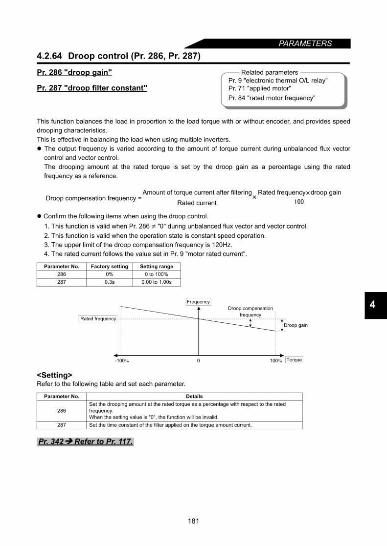
181
PARAMETERS
4
4.2.64 Droop control (Pr. 286, Pr. 287)
Pr. 286 "droop gain"
Pr. 287 "droop filter constant"
This function balances the load in proportion to the load torque with or without encoder, and provides speeddrooping characteristics.This is effective in balancing the load when using multiple inverters. The output frequency is varied according to the amount of torque current during unbalanced flux vector
control and vector control.The drooping amount at the rated torque is set by the droop gain as a percentage using the ratedfrequency as a reference.
Confirm the following items when using the droop control.1. This function is valid when Pr. 286 ≠ "0" during unbalanced flux vector and vector control.2. This function is valid when the operation state is constant speed operation.3. The upper limit of the droop compensation frequency is 120Hz.4. The rated current follows the value set in Pr. 9 "motor rated current".
<Setting>Refer to the following table and set each parameter.
Parameter No. Factory setting Setting range286 0% 0 to 100%287 0.3s 0.00 to 1.00s
Parameter No. Details
286Set the drooping amount at the rated torque as a percentage with respect to the rated frequency.When the setting value is "0", the function will be invalid.
287 Set the time constant of the filter applied on the torque amount current.
Related parametersPr. 9 "electronic thermal O/L relay"Pr. 71 "applied motor"Pr. 84 "rated motor frequency"
Droop compensation frequency =Amount of torque current after filtering
Rated currentRated frequency droop gain
100
Droop compensationfrequency
Torque100%
Droop gain
-100%
Frequency
0
Rated frequency
Pr. 342 Refer to Pr. 117.
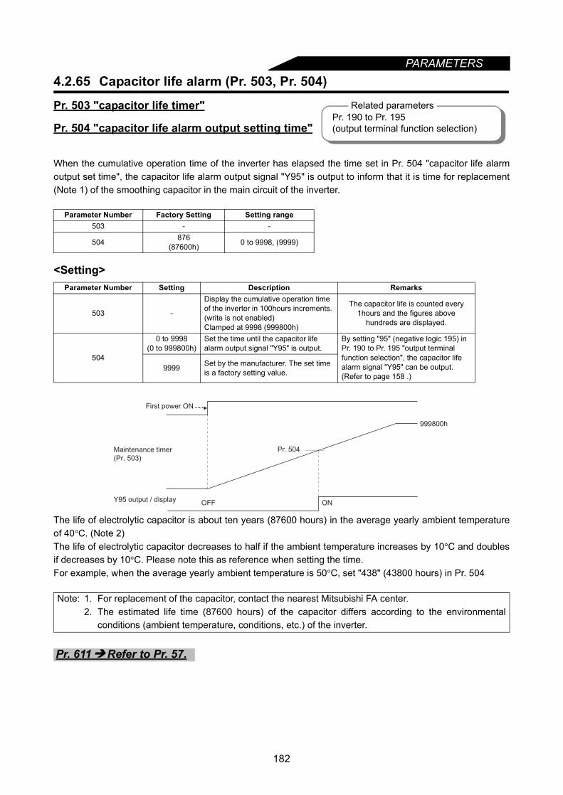
182
PARAMETERS4.2.65 Capacitor life alarm (Pr. 503, Pr. 504)
Pr. 503 "capacitor life timer"
Pr. 504 "capacitor life alarm output setting time"
When the cumulative operation time of the inverter has elapsed the time set in Pr. 504 "capacitor life alarmoutput set time", the capacitor life alarm output signal "Y95" is output to inform that it is time for replacement(Note 1) of the smoothing capacitor in the main circuit of the inverter.
<Setting>
The life of electrolytic capacitor is about ten years (87600 hours) in the average yearly ambient temperatureof 40°C. (Note 2)The life of electrolytic capacitor decreases to half if the ambient temperature increases by 10°C and doublesif decreases by 10°C. Please note this as reference when setting the time.For example, when the average yearly ambient temperature is 50°C, set "438" (43800 hours) in Pr. 504
Parameter Number Factory Setting Setting range503 - -
504 876(87600h) 0 to 9998, (9999)
Parameter Number Setting Description Remarks
503 -
Display the cumulative operation time of the inverter in 100hours increments. (write is not enabled)Clamped at 9998 (999800h)
The capacitor life is counted every 1hours and the figures above
hundreds are displayed.
504
0 to 9998(0 to 999800h)
Set the time until the capacitor life alarm output signal "Y95" is output.
By setting "95" (negative logic 195) in Pr. 190 to Pr. 195 "output terminal function selection", the capacitor life alarm signal "Y95" can be output. (Refer to page 158 .)
9999 Set by the manufacturer. The set time is a factory setting value.
Note: 1. For replacement of the capacitor, contact the nearest Mitsubishi FA center.2. The estimated life time (87600 hours) of the capacitor differs according to the environmental
conditions (ambient temperature, conditions, etc.) of the inverter.
Related parametersPr. 190 to Pr. 195 (output terminal function selection)
First power ON
Maintenance timer
(Pr. 503)
Y95 output / display OFF ON
Pr. 504
999800h
Pr. 611 Refer to Pr. 57.
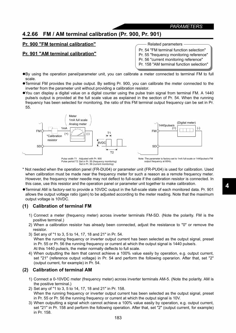
PARAMETERS
4
4.2.66 FM / AM terminal calibration (Pr. 900, Pr. 901)
Pr. 900 "FM terminal calibration"
Pr. 901 "AM terminal calibration"
By using the operation panel/parameter unit, you can calibrate a meter connected to terminal FM to fullscale.
Terminal FM provides the pulse output. By setting Pr. 900, you can calibrate the meter connected to theinverter from the parameter unit without providing a calibration resistor.
You can display a digital value on a digital counter using the pulse train signal from terminal FM. A 1440pulse/s output is provided at the full scale value as explained in the section of Pr. 54. When the runningfrequency has been selected for monitoring, the ratio of this FM terminal output frequency can be set in Pr.55.
* Not needed when the operation panel (FR-DU04) or parameter unit (FR-PU04) is used for calibration. Usedwhen calibration must be made near the frequency meter for such a reason as a remote frequency meter.However, the frequency meter needle may not deflect to full-scale if the calibration resistor is connected. Inthis case, use this resistor and the operation panel or parameter unit together to make calibration.
Terminal AM is factory-set to provide a 10VDC output in the full-scale state of each monitored data. Pr. 901allows the output voltage ratio (gain) to be adjusted according to the meter reading. Note that the maximumoutput voltage is 10VDC.
(1) Calibration of terminal FM
1) Connect a meter (frequency meter) across inverter terminals FM-SD. (Note the polarity. FM is thepositive terminal.)
2) When a calibration resistor has already been connected, adjust the resistance to "0" or remove theresistor.
3) Set any of "1 to 3, 5 to 14, 17, 18 and 21" in Pr. 54.When the running frequency or inverter output current has been selected as the output signal, presetin Pr. 55 or Pr. 56 the running frequency or current at which the output signal is 1440 pulse/s.At this 1440 pulse/s, the meter normally deflects to full scale.
4) When outputting the item that cannot achieve a 100% value easily by operation, e.g. output current,set "21" (reference output voltage) in Pr. 54 and perform the following operarion. After that, set "2"(output current, for example) in Pr. 54.
(2) Calibration of terminal AM
1) Connect a 0-10VDC meter (frequency meter) across inverter terminals AM-5. (Note the polarity. AM isthe positive terminal.)
2) Set any of "1 to 3, 5 to 14, 17, 18 and 21" in Pr. 158.When the running frequency or inverter output current has been selected as the output signal, presetin Pr. 55 or Pr. 56 the running frequency or current at which the output signal is 10V.
3) When outputting a signal which cannot achieve a 100% value easily by operation, e.g. output current,set "21" in Pr. 158 and perform the following operation. After that, set "2" (output current, for example)in Pr. 158.
Related parametersPr. 54 "FM terminal function selection"Pr. 55 "frequency monitoring reference"Pr. 56 "current monitoring reference"Pr. 158 "AM terminal function selection"
8VDC
T2
T1
(Digital meter)
(-)(+)1440pulse/s
FM
SD
Meter 1mA full scaleAnalog meter
(-)(+)
1mAFM
SD
*Calibration resistor
Pulse width T1 Pulse period T2
:Adjusted with Pr. 900:Set in Pr. 55 (frequency monitoring) Set in Pr. 56 (current monitoring)
Note: The parameter is factory-set to 1mA full-scale or 1440pulse/s FM output frequency at 60Hz.
183
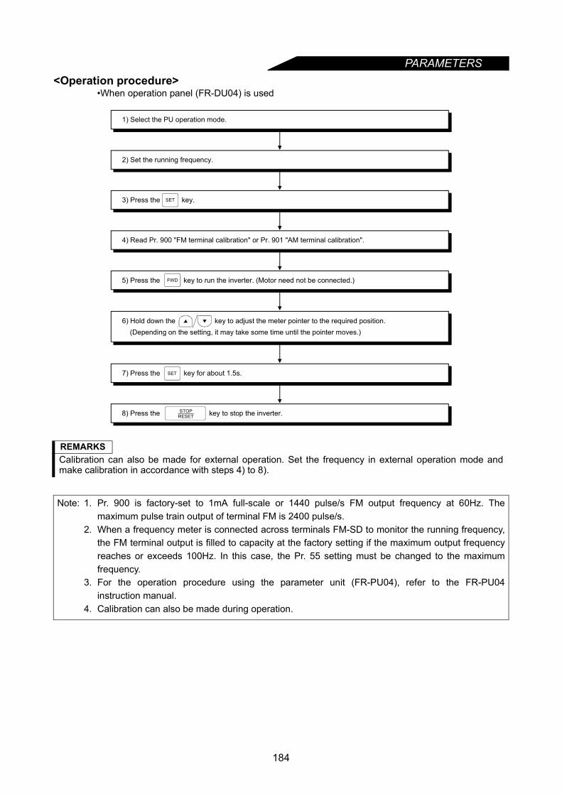
PARAMETERS
<Operation procedure>•When operation panel (FR-DU04) is used
REMARKSCalibration can also be made for external operation. Set the frequency in external operation mode andmake calibration in accordance with steps 4) to 8).
Note: 1. Pr. 900 is factory-set to 1mA full-scale or 1440 pulse/s FM output frequency at 60Hz. Themaximum pulse train output of terminal FM is 2400 pulse/s.
2. When a frequency meter is connected across terminals FM-SD to monitor the running frequency,the FM terminal output is filled to capacity at the factory setting if the maximum output frequencyreaches or exceeds 100Hz. In this case, the Pr. 55 setting must be changed to the maximumfrequency.
3. For the operation procedure using the parameter unit (FR-PU04), refer to the FR-PU04instruction manual.
4. Calibration can also be made during operation.
8) Press the key to stop the inverter.
1) Select the PU operation mode.
2) Set the running frequency.
3) Press the key.
4) Read Pr. 900 "FM terminal calibration" or Pr. 901 "AM terminal calibration".
5) Press the key to run the inverter. (Motor need not be connected.)
7) Press the key for about 1.5s.
6) Hold down the key to adjust the meter pointer to the required position. (Depending on the setting, it may take some time until the pointer moves.)
STOPRESET
FWD
SET
SET
184
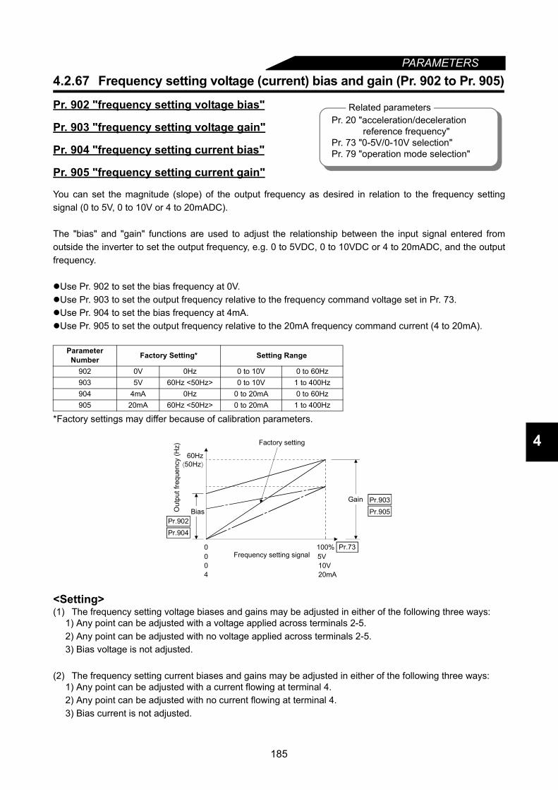
PARAMETERS
4
4.2.67 Frequency setting voltage (current) bias and gain (Pr. 902 to Pr. 905)
Pr. 902 "frequency setting voltage bias"
Pr. 903 "frequency setting voltage gain"
Pr. 904 "frequency setting current bias"
Pr. 905 "frequency setting current gain"
You can set the magnitude (slope) of the output frequency as desired in relation to the frequency settingsignal (0 to 5V, 0 to 10V or 4 to 20mADC).
The "bias" and "gain" functions are used to adjust the relationship between the input signal entered fromoutside the inverter to set the output frequency, e.g. 0 to 5VDC, 0 to 10VDC or 4 to 20mADC, and the outputfrequency.
Use Pr. 902 to set the bias frequency at 0V.Use Pr. 903 to set the output frequency relative to the frequency command voltage set in Pr. 73.Use Pr. 904 to set the bias frequency at 4mA.Use Pr. 905 to set the output frequency relative to the 20mA frequency command current (4 to 20mA).
*Factory settings may differ because of calibration parameters.
<Setting>(1) The frequency setting voltage biases and gains may be adjusted in either of the following three ways:
1) Any point can be adjusted with a voltage applied across terminals 2-5.2) Any point can be adjusted with no voltage applied across terminals 2-5.3) Bias voltage is not adjusted.
(2) The frequency setting current biases and gains may be adjusted in either of the following three ways:1) Any point can be adjusted with a current flowing at terminal 4.2) Any point can be adjusted with no current flowing at terminal 4.3) Bias current is not adjusted.
Parameter Number Factory Setting* Setting Range
902 0V 0Hz 0 to 10V 0 to 60Hz903 5V 60Hz <50Hz> 0 to 10V 1 to 400Hz904 4mA 0Hz 0 to 20mA 0 to 60Hz905 20mA 60Hz <50Hz> 0 to 20mA 1 to 400Hz
Related parametersPr. 20 "acceleration/deceleration reference frequency"Pr. 73 "0-5V/0-10V selection"Pr. 79 "operation mode selection"
Pr.902
Pr.904
Pr.903
Pr.73
Pr.905
Gain
Out
put f
requ
ency
(Hz)
Bias
Factory setting
Frequency setting signal004
05V10V20mA
100%
60Hz⟨50Hz⟩
185
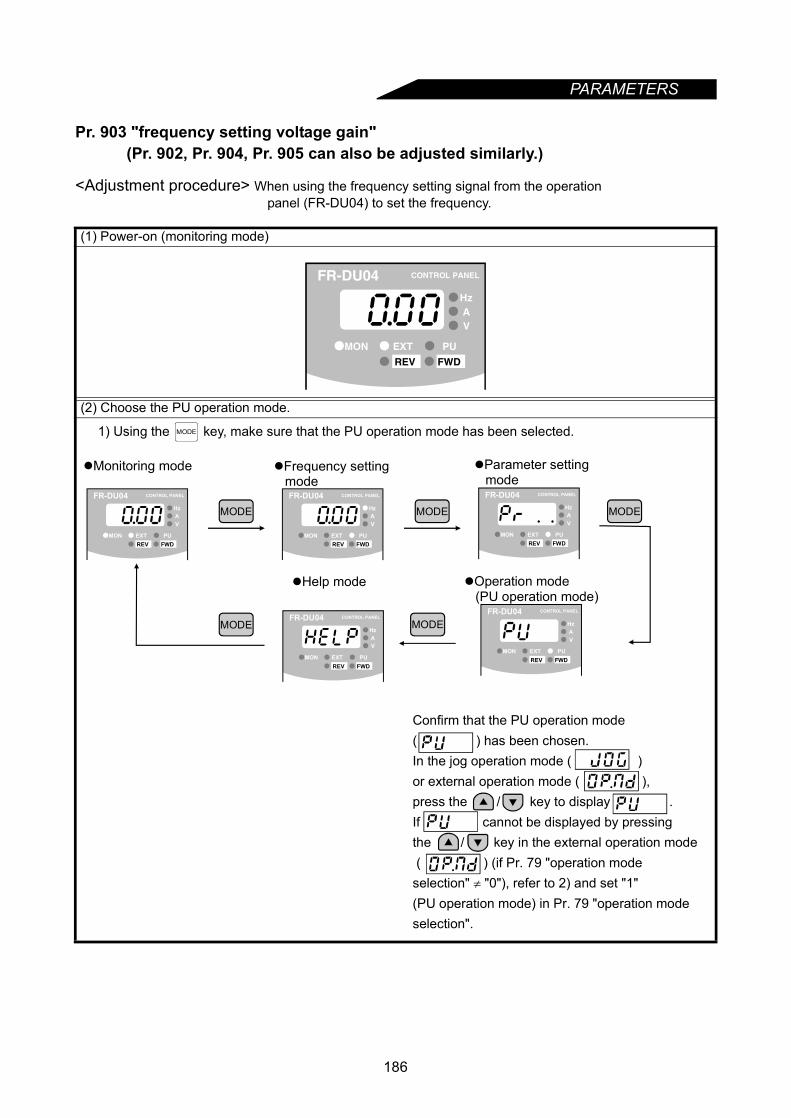
PARAMETERS
Pr. 903 "frequency setting voltage gain" (Pr. 902, Pr. 904, Pr. 905 can also be adjusted similarly.)
<Adjustment procedure> When using the frequency setting signal from the operation panel (FR-DU04) to set the frequency.
(1) Power-on (monitoring mode)
(2) Choose the PU operation mode.
1) Using the key, make sure that the PU operation mode has been selected.
FR-DU04 CONTROL PANEL
Hz
MON EXT PU
AV
REV FWD
MODE
Monitoring mode
MODE
Frequency setting mode
Parameter setting mode
Help mode Operation mode (PU operation mode)
MODE MODE
MODE MODE
Confirm that the PU operation mode ( ) has been chosen.In the jog operation mode ( ) or external operation mode ( ), press the / key to display .If cannot be displayed by pressing the / key in the external operation mode ( ) (if Pr. 79 "operation modeselection" ≠ "0"), refer to 2) and set "1"(PU operation mode) in Pr. 79 "operation modeselection".
FR-DU04 CONTROL PANEL
Hz
MON EXT PU
AV
REV FWD
FR-DU04 CONTROL PANEL
Hz
MON EXT PU
AV
REV FWD
FR-DU04 CONTROL PANEL
Hz
MON EXT PU
AV
REV FWD
FR-DU04 CONTROL PANEL
Hz
MON EXT PU
AV
REV FWD
FR-DU04 CONTROL PANEL
Hz
MON EXT PU
AV
REV FWD
186

PARAMETERS
4
2) Set "1" (PU operation mode) in Pr. 79 "operation mode selection".Example: To change the external operation mode (Pr. 79=2) to the PU operation mode (Pr. 79=1)
SET
SET
Current setting Setting change
Press for1.5 s
SET
Middle digit flickersMost significantdigit flickers
SET
Least significantdigit flickers
0 to 9
SET
Parameter setting mode
Using the key,
choose the "parameter
setting mode" as in 1).
MODE
×7 times ×9 times
Setting write
Flicker
0 to 9
If appears, make sure that the forwardrotation (STF) or reverse rotation (STR) signalconnected to the control terminal is not on.If it is on, turn it off.
SET
"1" (PU operation mode) has been set in Pr. 79.If appears, you did not press the key for 1.5s when writing the setting.Restart the procedure from the beginning.
FR-DU04 CONTROL PANEL
Hz
MON EXT PU
AV
REV FWD
Press the key once, press the key, andrestart the setting from the begining.
SET
187
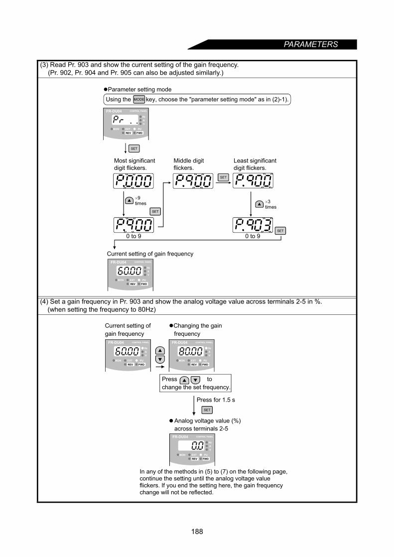
PARAMETERS
(3) Read Pr. 903 and show the current setting of the gain frequency.(Pr. 902, Pr. 904 and Pr. 905 can also be adjusted similarly.)
(4) Set a gain frequency in Pr. 903 and show the analog voltage value across terminals 2-5 in %. (when setting the frequency to 80Hz)
SET
0 to 9 0 to 9
Most significantdigit flickers.
Middle digitflickers.
Least significantdigit flickers.
Current setting of gain frequency
SET
SET
SET
Parameter setting modeUsing the key, choose the "parameter setting mode" as in (2)-1).MODE
×9times ×3
times
FR-DU04 CONTROL PANEL
Hz
MON EXT PU
AV
REV FWD
FR-DU04 CONTROL PANEL
Hz
MON EXT PU
AV
REV FWD
Press for 1.5 s
Current setting ofgain frequency
Changing the gain frequency
Press tochange the set frequency.
SET
In any of the methods in (5) to (7) on the following page, continue the setting until the analog voltage value flickers. If you end the setting here, the gain frequency change will not be reflected.
FR-DU04 CONTROL PANEL
Hz
MON EXT PU
AV
REV FWD
FR-DU04 CONTROL PANEL
Hz
MON EXT PU
AV
REV FWD
FR-DU04 CONTROL PANEL
Hz
MON EXT PU
AV
REV FWD
Analog voltage value (%) across terminals 2-5
188
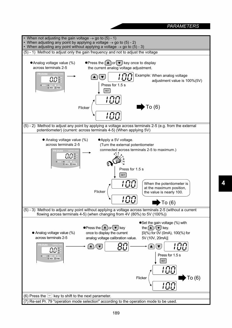
PARAMETERS
4
• When not adjusting the gain voltage → go to (5) - 1)• When adjusting any point by applying a voltage → go to (5) - 2)• When adjusting any point without applying a voltage → go to (5) - 3)(5) - 1) Method to adjust only the gain frequency and not to adjust the voltage
(5) - 2) Method to adjust any point by applying a voltage across terminals 2-5 (e.g. from the external potentiometer) (current: across terminals 4-5) (When applying 5V)
(5) - 3) Method to adjust any point without applying a voltage across terminals 2-5 (without a current flowing across terminals 4-5) (when changing from 4V (80%) to 5V (100%))
(6) Press the key to shift to the next parameter.(7) Re-set Pr. 79 "operation mode selection" according to the operation mode to be used.
Press for 1.5 sSET
Flicker
Press the or key once to display the current analog voltage adjustment.
Example: When analog voltageadjustment value is 100%(5V)
FR-DU04 CONTROL PANEL
Hz
MON EXT PU
AV
REV FWD
Analog voltage value (%)across terminals 2-5
To (6)
Press for 1.5 s
Flicker
Apply a 5V voltage. (Turn the external potentiometer connected across terminals 2-5 to maximum.)
SET
When the potentiometer isat the maximum position, the value is nearly 100.
FR-DU04 CONTROL PANEL
Hz
MON EXT PU
AV
REV FWD
Analog voltage value (%)across terminals 2-5
To (6)
Press for 1.5 s
Flicker
SET
Press the or key once to display the current analog voltage calibration value.
Set the gain voltage (%) with the key. [0(%) for 0V (0mA), 100(%) for 5V (10V, 20mA)]
/
/FR-DU04 CONTROL PANEL
Hz
MON EXT PU
AV
REV FWD
Analog voltage value (%)across terminals 2-5
To (6)
SET
189
PARAMETERS
4.2.68 PU buzzer control (Pr. 990)
Pr. 990 " PU buzzer control"
You can make the buzzer "beep" when you press any key of the operation panel or parameter unit.
Note: 1. If the Pr. 903 or Pr. 905 (gain adjustment) value is changed, the Pr. 20 value does not change.The input signal to terminal 1 (frequency setting auxiliary input) is added to the frequency settingsignal.
2. For the operation procedure using the parameter unit (FR-PU04), refer to the FR-PU04instruction manual.
CAUTIONBe careful when setting any value other than "0" as the bias frequency at 0V. Even without the speed command, the motor will start running at the set frequency by merely switching on the start signal.
Parameter Number
FactorySetting Setting Range Remarks
990 1 0,1 0: Without beep, 1: With beep
190

CHAPTER 5
PROTECTIVE FUNCTIONSChapter 1
Chapter 2
Chapter 3
Chapter 4
Chapter 5
Chapter 6
Chapter 7
Chapter 8
This chapter explains the "protective functions" for use of thisproduct.Always read the instructions and other information before using the equipment.
5.1 Errors (Alarms) ....................................................1925.2 Troubleshooting...................................................203
191
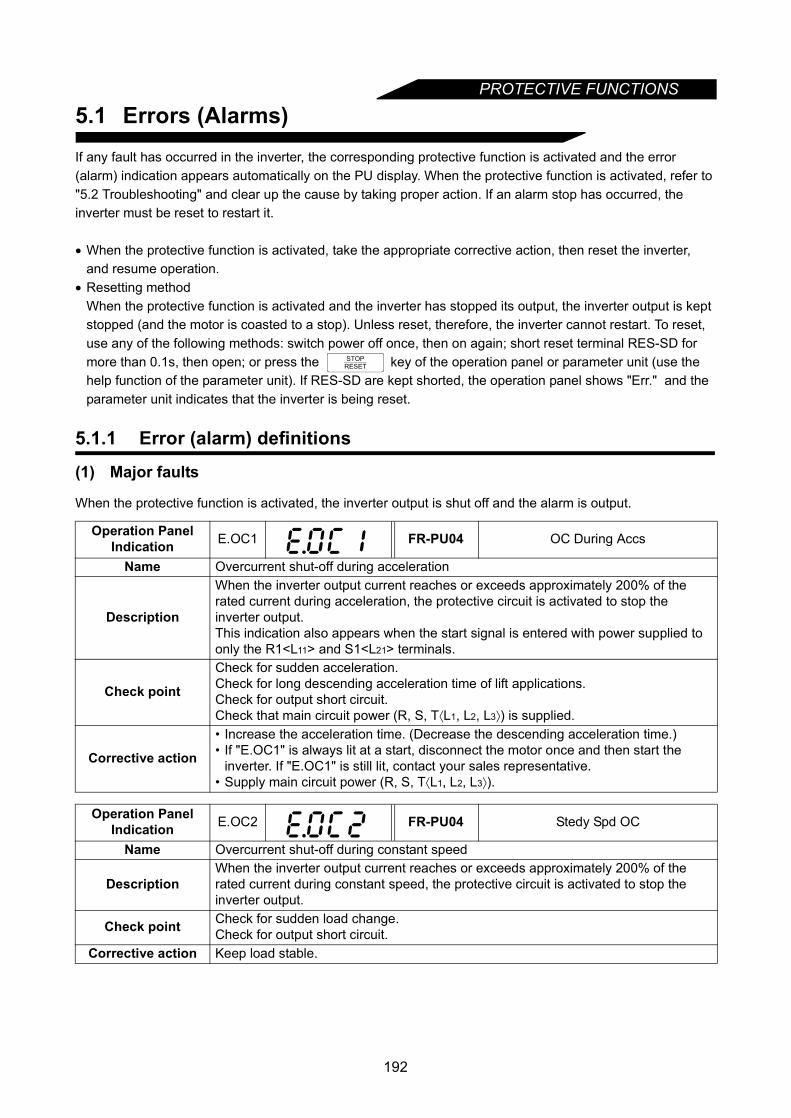
PROTECTIVE FUNCTIONS
5.1 Errors (Alarms)If any fault has occurred in the inverter, the corresponding protective function is activated and the error (alarm) indication appears automatically on the PU display. When the protective function is activated, refer to "5.2 Troubleshooting" and clear up the cause by taking proper action. If an alarm stop has occurred, the inverter must be reset to restart it.
• When the protective function is activated, take the appropriate corrective action, then reset the inverter, and resume operation.
• Resetting methodWhen the protective function is activated and the inverter has stopped its output, the inverter output is kept stopped (and the motor is coasted to a stop). Unless reset, therefore, the inverter cannot restart. To reset, use any of the following methods: switch power off once, then on again; short reset terminal RES-SD for more than 0.1s, then open; or press the key of the operation panel or parameter unit (use the help function of the parameter unit). If RES-SD are kept shorted, the operation panel shows "Err." and the parameter unit indicates that the inverter is being reset.
5.1.1 Error (alarm) definitions
(1) Major faults
When the protective function is activated, the inverter output is shut off and the alarm is output.
Operation Panel Indication E.OC1 FR-PU04 OC During Accs
Name Overcurrent shut-off during acceleration
Description
When the inverter output current reaches or exceeds approximately 200% of the rated current during acceleration, the protective circuit is activated to stop the inverter output.This indication also appears when the start signal is entered with power supplied to only the R1<L11> and S1<L21> terminals.
Check point
Check for sudden acceleration.Check for long descending acceleration time of lift applications.Check for output short circuit.Check that main circuit power (R, S, T⟨L1, L2, L3⟩) is supplied.
Corrective action
• Increase the acceleration time. (Decrease the descending acceleration time.)• If "E.OC1" is always lit at a start, disconnect the motor once and then start the
inverter. If "E.OC1" is still lit, contact your sales representative.• Supply main circuit power (R, S, T⟨L1, L2, L3⟩).
Operation Panel Indication E.OC2 FR-PU04 Stedy Spd OC
Name Overcurrent shut-off during constant speed
DescriptionWhen the inverter output current reaches or exceeds approximately 200% of the rated current during constant speed, the protective circuit is activated to stop the inverter output.
Check point Check for sudden load change.Check for output short circuit.
Corrective action Keep load stable.
STOPRESET
192

PROTECTIVE FUNCTIONS
5
Operation Panel Indication E.OC3 FR-PU04 OC During Dec
Name Overcurrent shut-off during deceleration
DescriptionWhen the inverter output current reaches or exceeds approximately 200% of the rated current during deceleration (other than acceleration or constant speed), the protective circuit is activated to stop the inverter output.
Check pointCheck for sudden speed reduction.Check for output short circuit.Check for too fast operation of motor's mechanical brake.
Corrective action Increase the deceleration time.Check mechanical brake operation.
Operation Panel Indication E.OV1 FR-PU04 OV During Acc
Name Regenerative overvoltage shut-off during acceleration
Description
A prealarm (RB indication) occurs if the inverter's internal main circuit DC voltage reaches or exceeds the specified value, the protective circuit is activated to stop the inverter output. It may also be activated by a surge voltage generated in the power supply system.
Check point Check for too slow acceleration. (e,g, during descending acceleration with lifting load)
Corrective action Decrease the acceleration time.
Operation Panel Indication E.OV2 FR-PU04 Stedy Spd OV
Name Regenerative overvoltage shut-off during constant speed
Description
A prealarm (RB indication) occurs if the inverter's internal main circuit DC voltage reaches or exceeds the specified value, the protective circuit is activated to stop the inverter output. It may also be activated by a surge voltage generated in the power supply system.
Check point Check for sudden load change.
Corrective action • Keep load stable.• Use the brake unit or power regeneration common converter (FR-CV) as required.
Operation Panel Indication E.OV3 FR-PU04 OV During Dec
Name Regenerative overvoltage shut-off during deceleration or stop
Description
A prealarm (RB indication) occurs if the inverter's internal main circuit DC voltage reaches or exceeds the specified value, the protective circuit is activated to stop the inverter output. It may also be activated by a surge voltage generated in the power supply system.
Check point Check for sudden speed reduction.
Corrective action
• Increase the deceleration time. (Set the deceleration time which matches the inertia moment of the load.)
• Decrease the braking duty.• Use the brake unit or power regeneration common converter (FR-CV) as required.
193
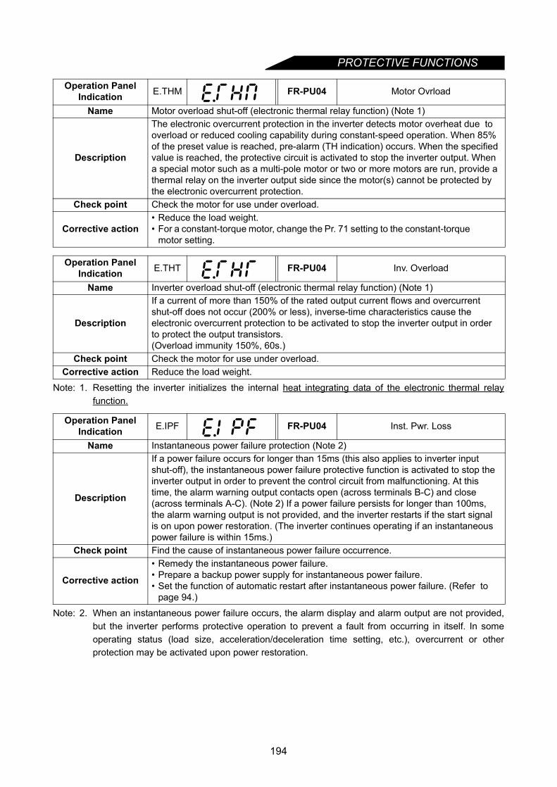
PROTECTIVE FUNCTIONS
Note: 1. Resetting the inverter initializes the internal heat integrating data of the electronic thermal relayfunction.
Note: 2. When an instantaneous power failure occurs, the alarm display and alarm output are not provided,but the inverter performs protective operation to prevent a fault from occurring in itself. In someoperating status (load size, acceleration/deceleration time setting, etc.), overcurrent or otherprotection may be activated upon power restoration.
Operation Panel Indication E.THM FR-PU04 Motor Ovrload
Name Motor overload shut-off (electronic thermal relay function) (Note 1)
Description
The electronic overcurrent protection in the inverter detects motor overheat due to overload or reduced cooling capability during constant-speed operation. When 85% of the preset value is reached, pre-alarm (TH indication) occurs. When the specified value is reached, the protective circuit is activated to stop the inverter output. When a special motor such as a multi-pole motor or two or more motors are run, provide a thermal relay on the inverter output side since the motor(s) cannot be protected by the electronic overcurrent protection.
Check point Check the motor for use under overload.
Corrective action• Reduce the load weight.• For a constant-torque motor, change the Pr. 71 setting to the constant-torque
motor setting.
Operation Panel Indication E.THT FR-PU04 Inv. Overload
Name Inverter overload shut-off (electronic thermal relay function) (Note 1)
Description
If a current of more than 150% of the rated output current flows and overcurrent shut-off does not occur (200% or less), inverse-time characteristics cause the electronic overcurrent protection to be activated to stop the inverter output in order to protect the output transistors.(Overload immunity 150%, 60s.)
Check point Check the motor for use under overload.Corrective action Reduce the load weight.
Operation Panel Indication E.IPF FR-PU04 Inst. Pwr. Loss
Name Instantaneous power failure protection (Note 2)
Description
If a power failure occurs for longer than 15ms (this also applies to inverter input shut-off), the instantaneous power failure protective function is activated to stop the inverter output in order to prevent the control circuit from malfunctioning. At this time, the alarm warning output contacts open (across terminals B-C) and close (across terminals A-C). (Note 2) If a power failure persists for longer than 100ms, the alarm warning output is not provided, and the inverter restarts if the start signal is on upon power restoration. (The inverter continues operating if an instantaneous power failure is within 15ms.)
Check point Find the cause of instantaneous power failure occurrence.
Corrective action
• Remedy the instantaneous power failure.• Prepare a backup power supply for instantaneous power failure.• Set the function of automatic restart after instantaneous power failure. (Refer to
page 94.)
194

PROTECTIVE FUNCTIONS
5
Note: 3. This function is activated only when OH has been set to any of Pr. 180 to Pr. 186 (input terminalfunction selection).
Operation Panel Indication E.UVT FR-PU04 Under Voltage
Name Undervoltage protection
Description
If the power supply voltage of the inverter reduces, the control circuit will not operate properly and will result in decreased motor torque or increased heat generation. To prevent this, if the power supply voltage reduces below 150V (about 300V for the 400V class), this function stops the inverter output.When a jumper is not connected across P/+-P1, the undervoltage protective function is activated.
Check point Check for start of large-capacity motor.Check that a jumper or DC reactor is connected across terminals P/+-P1.
Corrective action Check the power supply system equipment such as power supply.Connect a jumper or DC reactor across terminals P/+-P1.
Operation Panel Indication E.FIN FR-PU04 H/Sink O/Temp
Name Fin overheat
Description If the heatsink overheats, the temperature sensor is actuated to stop the inverter output.
Check point • Check for too high ambient temperature.• Check for heatsink clogging.
Corrective action Set the ambient temperature to within the specifications.
Operation Panel Indication E.GF FR-PU04 Ground Fault
Name Output side earth (ground) fault overcurrent protection
DescriptionThis function stops the inverter output if an earth (ground) fault overcurrent flowsdue to an earth (ground) fault which occurred on the inverter's output side (loadside).
Check point Check for an earth (ground) fault in the motor and connection cable.Corrective action Remedy the earth (ground) fault portion.
Operation Panel Indication E.OHT FR-PU04 OH Fault
Name External thermal relay operation (Note 3)
Description
If the external thermal relay provided for motor overheat protection or the internally mounted temperature relay in the motor switches on (contacts open), the inverter output is stopped. If the relay contacts are reset automatically, the inverter will not restart unless it is reset.
Check point• Check for motor overheating.• Check that the value of "7" (OH signal) is set correctly in any of Pr. 180 to Pr. 186
(input terminal function selection).Corrective action Reduce the load and operating duty.
195
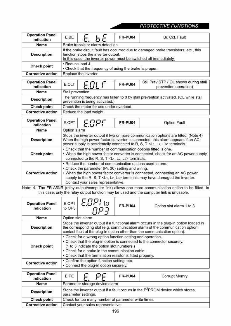
PROTECTIVE FUNCTIONS
Note: 4. The FR-A5NR (relay output/computer link) allows one more communication option to be fitted. Inthis case, only the relay output function may be used and the computer link is unusable.
Operation Panel Indication E.BE FR-PU04 Br. Cct. Fault
Name Brake transistor alarm detection
DescriptionIf the brake circuit fault has occurred due to damaged brake transistors, etc., this function stops the inverter output.In this case, the inverter power must be switched off immediately.
Check point • Reduce load J.• Check that the frequency of using the brake is proper.
Corrective action Replace the inverter.
Operation Panel Indication E.OLT FR-PU04 Still Prev STP ( OL shown during stall
prevention operation)Name Stall prevention
Description The running frequency has fallen to 0 by stall prevention activated. (OL while stall prevention is being activated.)
Check point Check the motor for use under overload.Corrective action Reduce the load weight.
Operation Panel Indication E.OPT FR-PU04 Option Fault
Name Option alarm
DescriptionStops the inverter output if two or more communication options are fitted. (Note 4) When the high power factor converter is connected, this alarm appears if an AC power supply is accidentally connected to R, S, T <L1, L2, L3> terminals.
Check point• Check that the number of communication options fitted is one.• When the high power factor converter is connected, check for an AC power supply
connected to the R, S, T <L1, L2, L3> terminals.
Corrective action
• Reduce the number of communication options used to one.• Check the parameter (Pr. 30) setting and wiring.• When the high power factor converter is connected, connecting an AC power
supply to the R, S, T <L1, L2, L3> terminals may have damaged the inverter. Contact your sales representative.
Operation Panel Indication
E.OP1 to OP3 FR-PU04 Option slot alarm 1 to 3
Name Option slot alarm
DescriptionStops the inverter output if a functional alarm occurs in the plug-in option loaded in the corresponding slot (e.g. communication alarm of the communication option, contact fault of the plug-in option other than the communication option).
Check point
• Check for a wrong option function setting and operation.• Check that the plug-in option is connected to the connector securely.
(1 to 3 indicate the option slot numbers.)• Check for a brake in the communication cable.• Check that the termination resistor is fitted properly.
Corrective action • Confirm the option function setting, etc.• Connect the plug-in option securely.
Operation Panel Indication E.PE FR-PU04 Corrupt Memry
Name Parameter storage device alarm
Description Stops the inverter output if a fault occurs in the E2PROM device which stores parameter settings.
Check point Check for too many number of parameter write times.Corrective action Contact your sales representative.
to
196

PROTECTIVE FUNCTIONS
5
Operation Panel Indication E.PUE FR-PU04 PU Leave Out
Name Parameter unit disconnection
Description
This function stops the inverter output if communication between the inverter and PU is suspended, e.g. the operation panel or PU is disconnected, when "2", "3", "16" or "17" was set in Pr. 75 "reset selection/disconnected PU detection/PU stop selection". This function stops the inverter output if the number of successive communication errors is greater than the permissible number of retries when the Pr. 121 ≠ "9999" for RS-485 communication from the PU connector. This function stops the inverter output if communication is broken for the time set in Pr. 122.
Check point • Check for loose fitting of the DU or PU.• Check the Pr. 75 setting.
Corrective action Fit the DU and PU securely.
Operation Panel Indication E.RET FR-PU04 Retry No Over
Name Retry count exceeded
Description If operation cannot be resumed properly within the number of retries set, this function stops the inverter output.
Check point Find the cause of alarm occurrence.Corrective action Eliminate the cause of the error preceding this error indication.
Operation Panel Indication E.LF FR-PU04
Name Output phase failure protection
Description • This function stops the inverter output if one of the three phases (U, V, W) on the inverter′s output side (load side) results in open phase.
Check point • Check the wiring (Check the motor for a fault).• Check that the capacity of the used motor is not smaller than the inverter capacity.
Corrective action • Check the cables properly.• Check the setting of Pr. 251 "output phase failure protection selection".
Operation Panel Indication E.CPU FR-PU04 CPU Fault
Name CPU error
Description If the arithmetic operation of the built-in CPU does not end within a predetermined period, the inverter self-determines it as an alarm and stops the output.
Check point
Corrective action • Make connection securely.• Contact your sales representative.
Operation Panel Indication
E. 1 to
E. 3FR-PU04 Fault 1 to Fault 3
Name Option fault
Description The inverter output is stopped if a contact fault occurs at the connector between the inverter and communication option, a fault of the communication option itself, etc. occurs.
Check point• Check that the communication option is plugged in the connector securely.(1 to 3 indicate the option slot numbers.)• Check for excess electrical noises around the inverter.
Corrective action
• Connect the communication option securely.• If there are any devices generating excess electrical noises around the inverter,
take measures against noises.• Contact your sales representative.
197
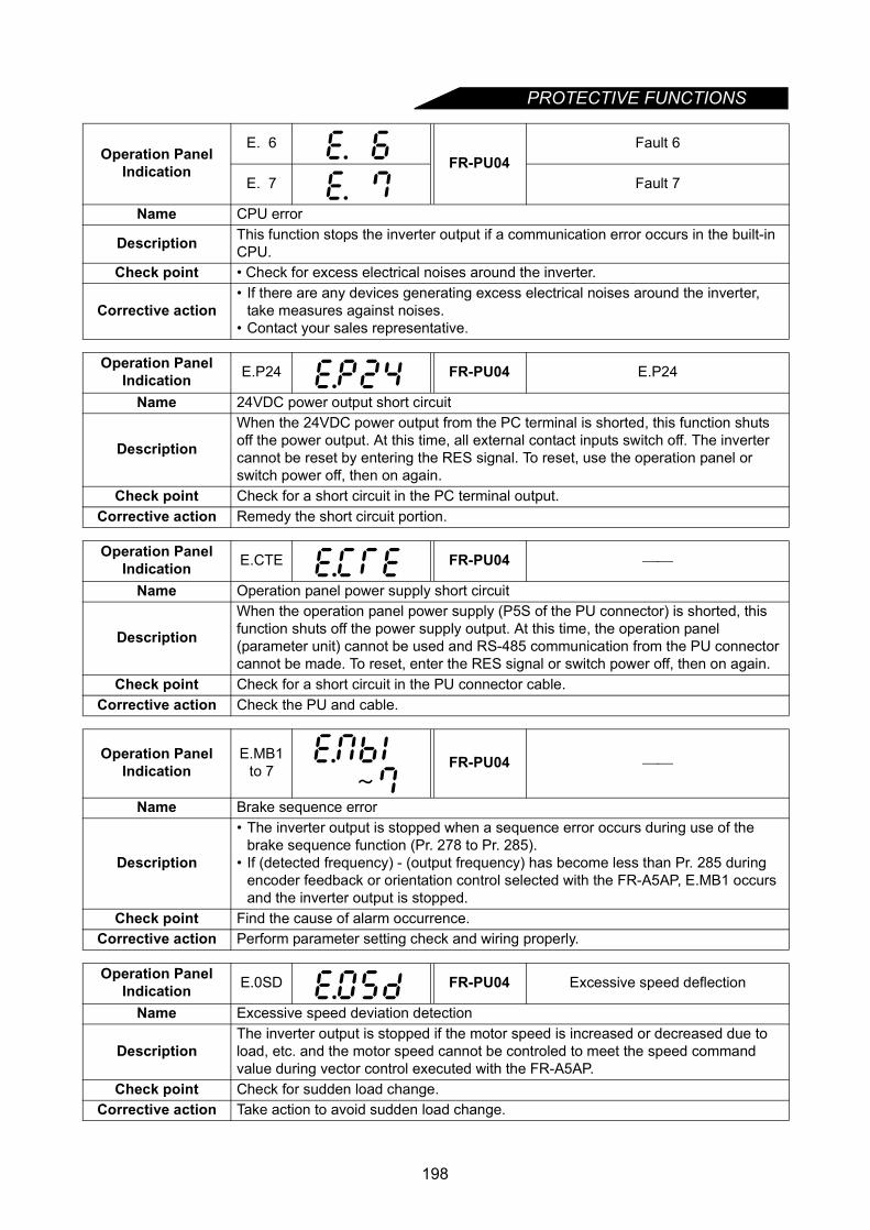
PROTECTIVE FUNCTIONS
Operation Panel Indication
E. 6FR-PU04
Fault 6
E. 7 Fault 7
Name CPU error
Description This function stops the inverter output if a communication error occurs in the built-in CPU.
Check point • Check for excess electrical noises around the inverter.
Corrective action• If there are any devices generating excess electrical noises around the inverter,
take measures against noises.• Contact your sales representative.
Operation Panel Indication E.P24 FR-PU04 E.P24
Name 24VDC power output short circuit
Description
When the 24VDC power output from the PC terminal is shorted, this function shuts off the power output. At this time, all external contact inputs switch off. The inverter cannot be reset by entering the RES signal. To reset, use the operation panel or switch power off, then on again.
Check point Check for a short circuit in the PC terminal output.Corrective action Remedy the short circuit portion.
Operation Panel Indication E.CTE FR-PU04
Name Operation panel power supply short circuit
Description
When the operation panel power supply (P5S of the PU connector) is shorted, this function shuts off the power supply output. At this time, the operation panel (parameter unit) cannot be used and RS-485 communication from the PU connector cannot be made. To reset, enter the RES signal or switch power off, then on again.
Check point Check for a short circuit in the PU connector cable.Corrective action Check the PU and cable.
Operation Panel Indication
E.MB1 to 7 FR-PU04
Name Brake sequence error
Description
• The inverter output is stopped when a sequence error occurs during use of the brake sequence function (Pr. 278 to Pr. 285).
• If (detected frequency) - (output frequency) has become less than Pr. 285 during encoder feedback or orientation control selected with the FR-A5AP, E.MB1 occurs and the inverter output is stopped.
Check point Find the cause of alarm occurrence.Corrective action Perform parameter setting check and wiring properly.
Operation Panel Indication E.0SD FR-PU04 Excessive speed deflection
Name Excessive speed deviation detection
DescriptionThe inverter output is stopped if the motor speed is increased or decreased due to load, etc. and the motor speed cannot be controled to meet the speed command value during vector control executed with the FR-A5AP.
Check point Check for sudden load change.Corrective action Take action to avoid sudden load change.
198
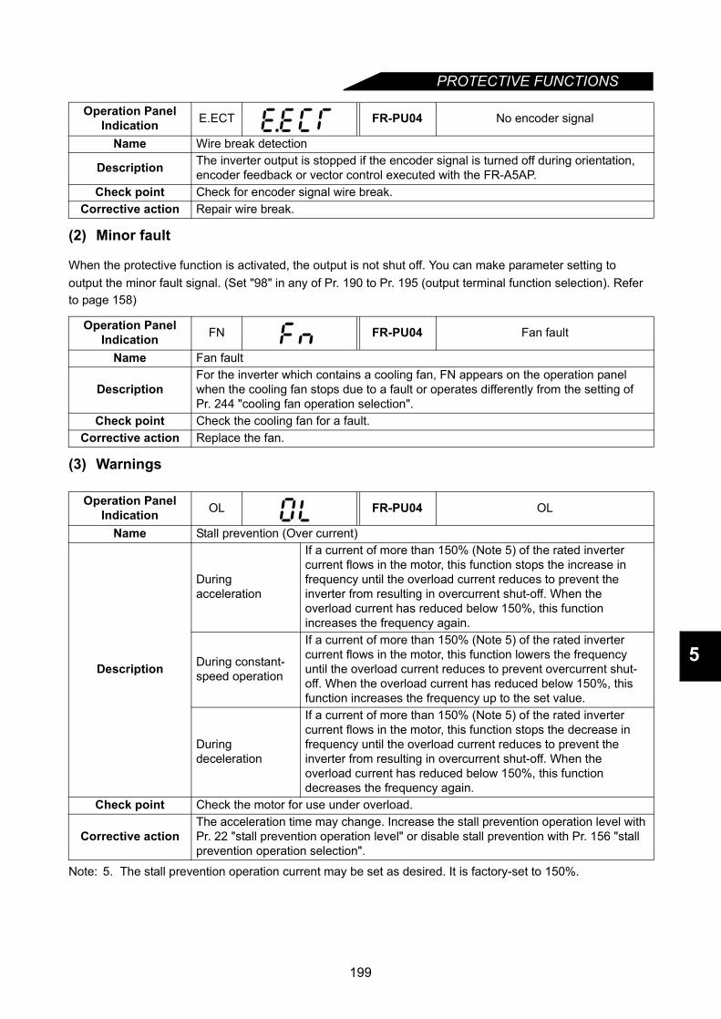
PROTECTIVE FUNCTIONS
5
(2) Minor fault
When the protective function is activated, the output is not shut off. You can make parameter setting to output the minor fault signal. (Set "98" in any of Pr. 190 to Pr. 195 (output terminal function selection). Refer to page 158)
(3) Warnings
Note: 5. The stall prevention operation current may be set as desired. It is factory-set to 150%.
Operation Panel Indication E.ECT FR-PU04 No encoder signal
Name Wire break detection
Description The inverter output is stopped if the encoder signal is turned off during orientation, encoder feedback or vector control executed with the FR-A5AP.
Check point Check for encoder signal wire break.Corrective action Repair wire break.
Operation Panel Indication FN FR-PU04 Fan fault
Name Fan fault
DescriptionFor the inverter which contains a cooling fan, FN appears on the operation panel when the cooling fan stops due to a fault or operates differently from the setting of Pr. 244 "cooling fan operation selection".
Check point Check the cooling fan for a fault.Corrective action Replace the fan.
Operation Panel Indication OL FR-PU04 OL
Name Stall prevention (Over current)
Description
During acceleration
If a current of more than 150% (Note 5) of the rated inverter current flows in the motor, this function stops the increase in frequency until the overload current reduces to prevent the inverter from resulting in overcurrent shut-off. When the overload current has reduced below 150%, this function increases the frequency again.
During constant-speed operation
If a current of more than 150% (Note 5) of the rated inverter current flows in the motor, this function lowers the frequency until the overload current reduces to prevent overcurrent shut-off. When the overload current has reduced below 150%, this function increases the frequency up to the set value.
During deceleration
If a current of more than 150% (Note 5) of the rated inverter current flows in the motor, this function stops the decrease in frequency until the overload current reduces to prevent the inverter from resulting in overcurrent shut-off. When the overload current has reduced below 150%, this function decreases the frequency again.
Check point Check the motor for use under overload.
Corrective actionThe acceleration time may change. Increase the stall prevention operation level with Pr. 22 "stall prevention operation level" or disable stall prevention with Pr. 156 "stall prevention operation selection".
199

PROTECTIVE FUNCTIONS
Operation Panel Indication oL FR-PU04 oL
Name Stall prevention (overvoltage)
Description During deceleration
If the regenerative energy of the motor increases too much to exceed the brake capability, this function stops the decrease in frequency to prevent overvoltage shut-off. As soon as the regenerative energy has reduced, deceleration resumes.
Check point Check for sudden speed reduction.
Corrective action The deceleration time may change. Increase the deceleration time using Pr. 8 "deceleration time".
Operation Panel Indication PS FR-PU04 PS
Name PU stop
Description A stop made by pressing the key of the PU has been set in Pr. 75 "PU stop selection".
Check point Check for a stop made by pressing the key of the operation panel.
Corrective action Refer to page 106.
Operation Panel Indication RB FR-PU04 RB
Name Regenerative brake prealarm
Description
This alarm appears if the regenerative brake duty reaches 85% of the value set in Pr. 70 "special regenerative brake duty".Regenerative overvoltage (E.OV_) occurs if the regenerative brake duty reaches 100%.
Check point Check that the brake resistor is not used frequently.Corrective action Increase the deceleration time.
Operation Panel Indication TH FR-PU04 TH
Name Electronic overcurrent protection prealarm
DescriptionThis alarm appears if the cumulative value of the electronic overcurrent protection reaches 85% of the preset level. If it reaches 100% of the preset level, motor overload shutoff (E.THM) occurs.
Check point Check for large load or sudden acceleration.Corrective action Reduce the load volume or the frequency of operation.
Operation Panel Indication Err.
Description
This alarm appears if: • The RES signal is on.• You attempted to set any parameter value in external operation mode.• You attempted to change the operation mode during operation.• You attempted to set any parameter value outside its setting range.• Normal communication cannot be made between the PU and inverter.• You attempted to set any parameter value during operation
(while signal STF or STR is ON).• You attempted to make parameter setting when Pr. 77 "parameter write disable
selection" has been set to disable parameter write.Corrective action Perform operation correctly.
STOPRESET
STOPRESET
200

PROTECTIVE FUNCTIONS
5
5.1.2 To know the operating status at the occurrence of an alarmWhen any alarm has occurred, the display automatically switches to the indication of the correspondingprotective function (error). By pressing the key at this point without resetting the inverter, the display shows the output frequency. In this way, it is possible to know the running frequency at the occurrence of thealarm. This also applies to the current. After resetting, you can confirm the data in the alarm history (refer topage 54).
5.1.3 Correspondences between digital and actual charactersThere are the following correspondences between the actual alphanumeric characters and the digitalcharacters displayed on the operation panel:
Actual Digital Actual Digital Actual Digital
MODE
0
1
2
3
4
5
6
7
8
9
A
B
C
E
F
G
H
I
J
L
D
M
N
O
P
T
U
V
r
-
o
S
201
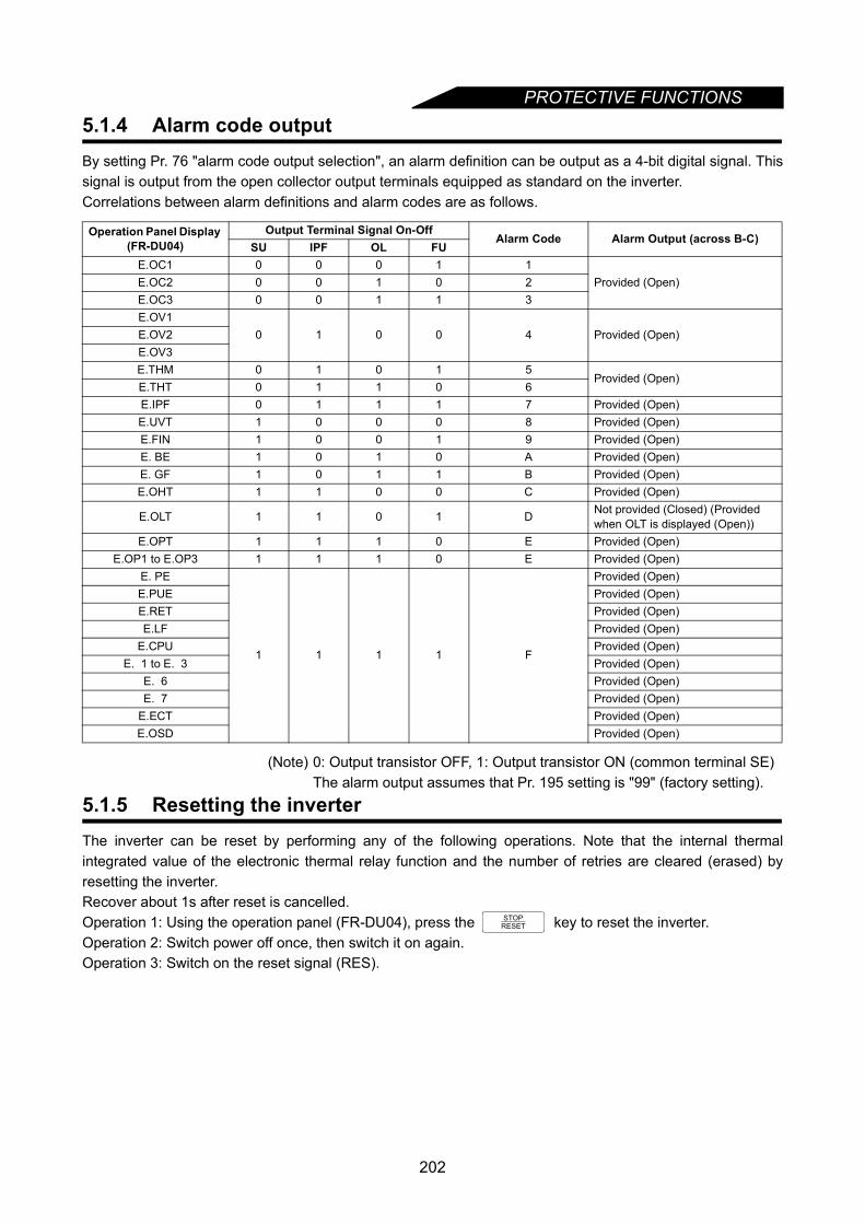
PROTECTIVE FUNCTIONS
5.1.4 Alarm code outputBy setting Pr. 76 "alarm code output selection", an alarm definition can be output as a 4-bit digital signal. Thissignal is output from the open collector output terminals equipped as standard on the inverter.Correlations between alarm definitions and alarm codes are as follows.(Note) 0: Output transistor OFF, 1: Output transistor ON (common terminal SE)The alarm output assumes that Pr. 195 setting is "99" (factory setting).
5.1.5 Resetting the inverterThe inverter can be reset by performing any of the following operations. Note that the internal thermalintegrated value of the electronic thermal relay function and the number of retries are cleared (erased) byresetting the inverter.Recover about 1s after reset is cancelled.Operation 1: Using the operation panel (FR-DU04), press the key to reset the inverter.Operation 2: Switch power off once, then switch it on again.Operation 3: Switch on the reset signal (RES).
Operation Panel Display (FR-DU04)
Output Terminal Signal On-OffAlarm Code Alarm Output (across B-C)
SU IPF OL FUE.OC1 0 0 0 1 1
Provided (Open)E.OC2 0 0 1 0 2E.OC3 0 0 1 1 3E.OV1
0 1 0 0 4 Provided (Open)E.OV2E.OV3E.THM 0 1 0 1 5
Provided (Open) E.THT 0 1 1 0 6E.IPF 0 1 1 1 7 Provided (Open)E.UVT 1 0 0 0 8 Provided (Open)E.FIN 1 0 0 1 9 Provided (Open)E. BE 1 0 1 0 A Provided (Open)E. GF 1 0 1 1 B Provided (Open)E.OHT 1 1 0 0 C Provided (Open)
E.OLT 1 1 0 1 D Not provided (Closed) (Provided when OLT is displayed (Open))
E.OPT 1 1 1 0 E Provided (Open)E.OP1 to E.OP3 1 1 1 0 E Provided (Open)
E. PE
1 1 1 1 F
Provided (Open)E.PUE Provided (Open)E.RET Provided (Open)E.LF Provided (Open)
E.CPU Provided (Open)E. 1 to E. 3 Provided (Open)
E. 6 Provided (Open)E. 7 Provided (Open)
E.ECT Provided (Open)E.OSD Provided (Open)
STOPRESET
202
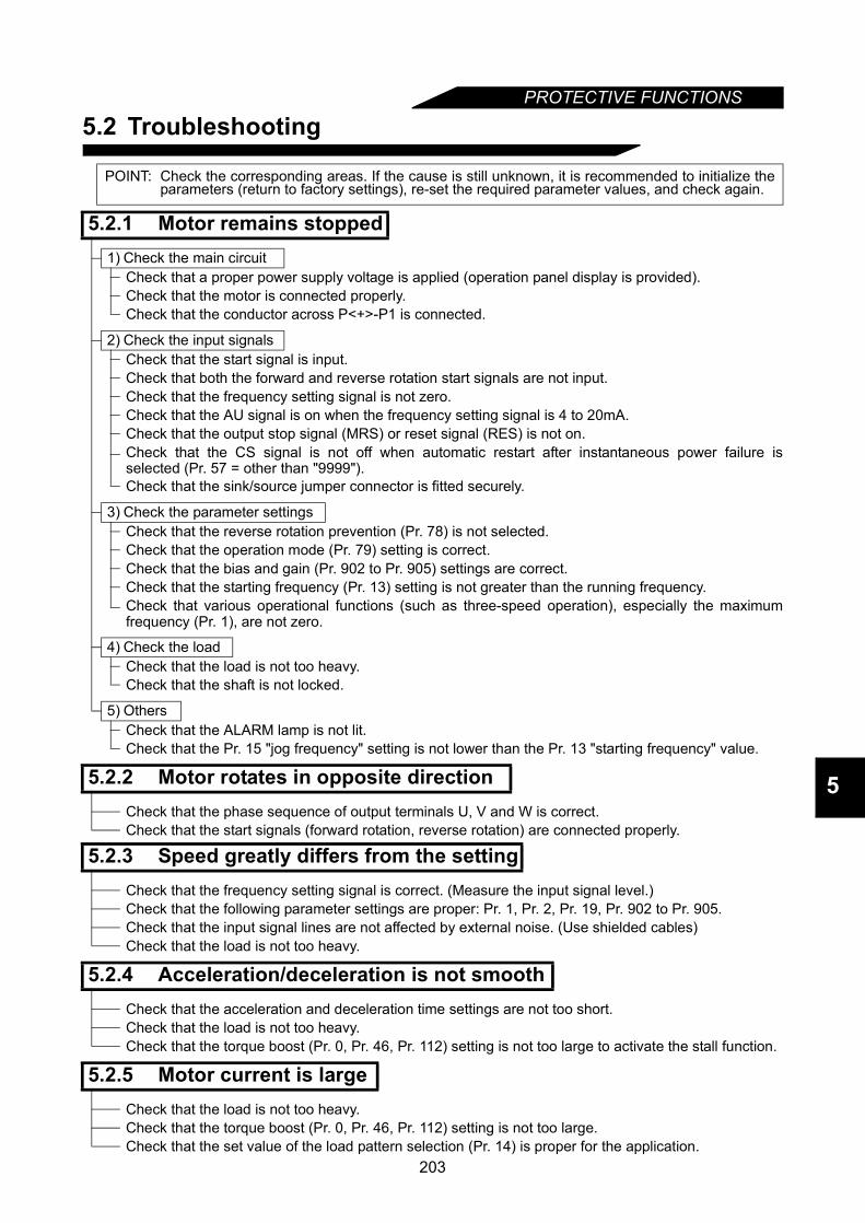
PROTECTIVE FUNCTIONS
5
5.2 Troubleshooting
POINT: Check the corresponding areas. If the cause is still unknown, it is recommended to initialize theparameters (return to factory settings), re-set the required parameter values, and check again.
5.2.1 Motor remains stopped1) Check the main circuit
Check that a proper power supply voltage is applied (operation panel display is provided).Check that the motor is connected properly.Check that the conductor across P<+>-P1 is connected.
2) Check the input signalsCheck that the start signal is input.Check that both the forward and reverse rotation start signals are not input.Check that the frequency setting signal is not zero.Check that the AU signal is on when the frequency setting signal is 4 to 20mA.Check that the output stop signal (MRS) or reset signal (RES) is not on.Check that the CS signal is not off when automatic restart after instantaneous power failure isselected (Pr. 57 = other than "9999").Check that the sink/source jumper connector is fitted securely.
3) Check the parameter settingsCheck that the reverse rotation prevention (Pr. 78) is not selected.Check that the operation mode (Pr. 79) setting is correct.Check that the bias and gain (Pr. 902 to Pr. 905) settings are correct.Check that the starting frequency (Pr. 13) setting is not greater than the running frequency.Check that various operational functions (such as three-speed operation), especially the maximumfrequency (Pr. 1), are not zero.
4) Check the loadCheck that the load is not too heavy.Check that the shaft is not locked.
5) OthersCheck that the ALARM lamp is not lit.Check that the Pr. 15 "jog frequency" setting is not lower than the Pr. 13 "starting frequency" value.
5.2.2 Motor rotates in opposite directionCheck that the phase sequence of output terminals U, V and W is correct.Check that the start signals (forward rotation, reverse rotation) are connected properly.
5.2.3 Speed greatly differs from the settingCheck that the frequency setting signal is correct. (Measure the input signal level.)Check that the following parameter settings are proper: Pr. 1, Pr. 2, Pr. 19, Pr. 902 to Pr. 905.Check that the input signal lines are not affected by external noise. (Use shielded cables)Check that the load is not too heavy.
5.2.4 Acceleration/deceleration is not smoothCheck that the acceleration and deceleration time settings are not too short.Check that the load is not too heavy.Check that the torque boost (Pr. 0, Pr. 46, Pr. 112) setting is not too large to activate the stall function.
5.2.5 Motor current is largeCheck that the load is not too heavy.Check that the torque boost (Pr. 0, Pr. 46, Pr. 112) setting is not too large.Check that the set value of the load pattern selection (Pr. 14) is proper for the application.
203
PROTECTIVE FUNCTIONS
5.2.6 Speed does not increaseCheck that the maximum frequency (Pr. 1) setting is correct.Check that the load is not too heavy. (In agitators, etc., load may become heavy in winter.)Check that the torque boost (Pr. 0, Pr. 46, Pr. 112) setting is not too large to activate the stallprevention function.Check that the brake resistor is not connected to terminals P<+>-P1 or terminals P1-PR accidentally.
5.2.7 Speed varies during operationDuring operation under advanced magnetic flux vector control, the output frequency varies with loadfluctuation between 0 and 2Hz. This is a normal operation and is not a fault.1) Inspection of load
Check that the load is not varying.
2) Inspection of input signalCheck that the frequency setting signal is not varying.Check that the frequency setting signal is not affected by induced noise.Check that a malfunction does not occur due to an undesirable current when the transistor output unitis connected, for example. (Refer to page 21.)
3) OthersCheck that the settings of the applied motor capacity (Pr. 80) and the number of applied motor poles(Pr. 81) are correct for the inverter and motor capacities in advanced magnetic flux vector control.Check that the wiring length is within 30m (98.42 feet) in advanced magnetic flux vector control.Check that the wiring length is correct in V/F control.
5.2.8 Operation mode is not changed properlyIf the operation mode is not changed properly, check the following:1) External input signal .............. Check that the STF or STR signal is off.
When it is on, the operation mode cannot be changed.
2) Parameter setting .............. Check the Pr. 79 setting.When the setting of Pr. 79 "operation mode selection" is "0" (factorysetting), switching input power on places the inverter in externaloperation mode. Press the operation panel's key two times andpress the key (press the key for the parameter unit(FR-PU04)). This changes the external operation mode into the PUoperation mode. For any other setting (1 to 8), the operation mode islimited according to the setting.
5.2.9 Operation panel (FR-DU04) display is not providedMake sure that the operation panel is connected securely with the inverter.
5.2.10 POWER lamp is not litMake sure that the wiring and installation are correct.
5.2.11 Parameter write cannot be performedCheck that operation is not being performed (signal STF or STR is not ON).Check that the key ( key) is pressed for longer than 1.5 s.Check that you are not attempting to make parameter setting outside the setting range.Check that you are not attempting to make parameter setting in external operation mode.Check the setting of Pr. 77 "parameter write disable selection".
MODE
PU
SET WRITE
204
CHAPTER 6
PRECAUTIONS FOR MAINTENANCE AND INSPECTIONChapter 1
Chapter 2
Chapter 3
Chapter 4
Chapter 5
Chapter 6
Chapter 7
Chapter 8
This chapter provides the "precautions for maintenance and inspection" of this product.Always read the instructions and other information before usingthe equipment.
6.1 Precautions for maintenance and inspection ............206
205
PRECAUTIONS FOR MAINTENANCE AND INSPECTION
6.1 Precautions for maintenance and inspectionThe transistorized inverter is a static unit mainly consisting of semiconductor devices. Daily inspection mustbe performed to prevent any fault from occurring due to adverse influence by the operating environment,such as temperature, humidity, dust, dirt and vibration, changes in the parts with time, service life, and otherfactors.
6.1.1 Precautions for maintenance and inspectionFor some short time after the power is switched off, a high voltage remains in the smoothing capacitor. Whenaccessing the inverter for inspection, switch power off. When more than 10 minutes have elapsed, make surethat the voltage across the main circuit terminals P<+>-N<-> of the inverter is 30VDC or less using a tester,etc.
6.1.2 Check items
(1) Daily inspections
• Check the following:1)Motor operation fault2)Improper installation environment3)Cooling system fault4)Unusual vibration and noise5)Unusual overheating and discoloration
• During operation, check the inverter input voltages using a tester.
(2) Cleaning
Always run the inverter in a clean state.When cleaning the inverter, gently wipe dirty areas with a soft cloth immersed in neutral detergent or ethanol.
6.1.3 Periodic inspectionCheck the areas inaccessible during operation and requiring periodic inspection. For periodic inspection,consult us.1) Cooling system fault : Clean the air filter, etc.2) Tightening check and retightening : The screws and bolts may become loose due to vibration,
temperature changes, etc. Check and tighten them. Tightenthem according to the specified tightening torque.
3) Check the conductors and insulating materials for corrosion and damage.4) Measure insulation resistance.5) Check and replace the cooling fan and relay.
Note: Do not use solvent, such as acetone, benzene, toluene and alcohol, as they will cause the invertersurface paint to peel off.Do not use detergent or alcohol to clean the display and other sections of the operation panel (FR-DU04) or parameter unit (FR-PU04) as these sections may deform.
206

PRECAUTIONS FOR MAINTENANCE AND INSPECTION
6
6.1.4 Insulation resistance test using megger1) Before performing the insulation resistance test using a megger on the external circuit, disconnect the
cables from all terminals of the inverter so that the test voltage is not applied to the inverter.2) For the continuity test of the control circuit, use a meter (high resistance range) and do not use the megger
or buzzer.3) For the inverter, conduct the insulation resistance test on the main circuit only as shown below and do not
perform the test on the control circuit. (Use a 500VDC megger.)
6.1.5 Pressure testDo not conduct a pressure test. The inverter's main circuit uses semiconductors, which may be deterioratedif a pressure test is made.
6.1.6 Daily and periodic inspection
Area of Inspec-
tionInspec-
tion Item Description
Interval
Method Criterion InstrumentCus-
tomerscheckDaily
Periodic1
year2
year
General
Surround-ing environ-ment
Check ambient temperature, humidity, dust, dirt, etc.
(Refer to page 10)
Ambient temperature:(constant torque) -10°C to +50°C (14°F to 122°F), non-freezing.(Variable torque) -10°C to +40°C (14°F to 104°F), non-freezing Ambient humidity: 90% or less, non-condensing.
Thermo-meter, hygrometer, recorder
Overall unit
Check for unusual vibration and noise.
Visual and auditory checks. No fault.
Power supply voltage
Check that the main circuit voltages are normal.
Measure voltages across the inverter terminal block R-S-T <L1-L2-L3> phases.
Within permissible AC voltage fluctuation (Refer to page 216)
Tester, digital multimeter
Main circuit
General
(1) Check with megger (across main circuit terminals and earth (ground) terminal).
(2) Check for loose screws and bolts.
(3) Check for overheat traces on the parts.
(4) Clean.
(1) Disconnect all cables from the inverter and measure across terminals R, S, T, U, V, W <L1, L2, L3, U, V, W> and earth (ground) terminal with megger.
(2) Re-tighten.(3) Visual check.
(1) 5M Ω or more.
(2), (3) No fault.
500VDC class megger
Conduc-tors, cables
(1) Check conductors for distortion.
(2) Check cable sheaths for breakage.
(1), (2) Visual check. (1), (2) No fault.
UV
WIM
InverterMotor
Powersupply
500VDCmegger
Earth (ground) terminal
R ⟨L1⟩
S ⟨L2⟩
T ⟨L3⟩
207
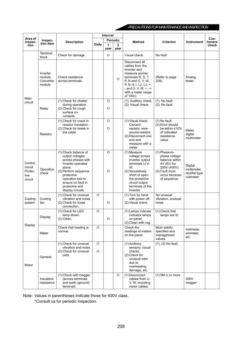
PRECAUTIONS FOR MAINTENANCE AND INSPECTION
Note: Values in parentheses indicate those for 400V class.*Consult us for periodic inspection.
Main circuit
Terminal block Check for damage. Visual check. No fault
Inverter module,Converter module
Check resistance across terminals.
Disconnect all cables from the inverter and measure across terminals R, S, T, P, N and U, V, W, P, N <L1, L2, L3, +, - and U, V, W, +, -> with a meter range of 100Ω.
(Refer to page 209)
Analog tester
Relay
(1) Check for chatter during operation.
(2) Check for rough surface on contacts.
(1) Auditory check.(2) Visual check.
(1) No fault.(2) No fault.
Resistor
(1) Check for crack in resistor insulation.
(2) Check for break in the cable.
(1) Visual check. Cement resistor, wire-wound resistor.
(2) Disconnect one end and measure with a meter.
(1) No fault.(2) Error should
be within ±10% of indicated resistance value.
Meter, digital multimeter
Control circuitProtec-tive circuit
Operation check
(1) Check balance of output voltages across phases with inverter operated alone.
(2) Perform sequence protective operation test to ensure no fault in protective and display circuits.
(1) Measure voltage across inverter output terminals U-V-W.
(2) Simulatively short or open the protective circuit output terminals of the inverter.
(1) Phase-to-phase voltage balance within 4V (8V) for 200V (400V).
(2) Fault must occur because of sequence.
Digital multimeter, rectifier type voltmeter
Cooling system
Cooling fan
(1) Check for unusual vibration and noise.
(2) Check for loose connection.
(1) Turn by hand with power off.
(2) Visual check.
No unusual vibration, unusual noise.
Display
Display
(1) Check for LED lamp blown.
(2) Clean.
(1) Lamps indicate indicator lamps on panel.
(2) Clean with rag.
(1) Check that lamps are lit.
Meter
Check that reading is normal.
Check the readings of meters on the panel.
Must satisfy specified and management values.
Voltmeter, ammeter, etc.
Motor
General
(1) Check for unusual vibration and noise.
(2) Check for unusual odor.
(1) Auditory, sensory, visual checks.
(2) Check for unusual odor due to overheating, damage, etc.
(1), (2) No fault.
Insulation resistance
(1) Check with megger (across terminals and earth (ground) terminal).
(1) Disconnect cables from U, V, W, including motor cables.
(1) 5M Ω or more500V megger
Area of Inspec-
tionInspec-
tion Item Description
Interval
Method Criterion InstrumentCus-
tomerscheckDaily
Periodic1
year2
year
208

PRECAUTIONS FOR MAINTENANCE AND INSPECTION
6
Checking the inverter and converter modules
<Preparation>(1) Disconnect the external power supply cables (R, S, T <L1, L2, L3>) and motor cables (U, V, W).(2) Prepare a tester. (Use 100Ω range.)
<Checking method>Change the polarity of the tester alternately at the inverter terminals R, S, T, U, V, W, P and N <L1, L2, L3, U,V, W, + and ->, and check for continuity.
<Module device numbers and terminals to be checked>
(Assumes the use of an analog meter.)
Note: 1. Before measurement, check that the smoothing capacitor is discharged.2. At the time of discontinuity, due to the smothing capacitor, the tester may not indicate . At the
time of continuity, the measured value is several to several ten's-of ohms depending on themodule type, circuit tester type, etc. If all measured values are almost the same, the modules arewithout fault.
Tester PolarityMeasured Value
Tester PolarityMeasured Value
Con
verte
r mod
ule
D1R <L1> P <+> Discontinuity
D4R <L1> N <-> Continuity
P <+> R <L1> Continuity N <-> R <L1> Discontinuity
D2S <L2> P <+> Discontinuity
D5S <L2> N <-> Continuity
P <+> S <L2> Continuity N <-> S <L2> Discontinuity
D3T <L3> P <+> Discontinuity
D6T <L3> N <-> Continuity
P <+> T <L3> Continuity N <-> T <L3> Discontinuity
Inve
rter m
odul
e TR1U P <+> Discontinuity
TR4U N <-> Continuity
P <+> U Continuity N <-> U Discontinuity
TR3V P <+> Discontinuity
TR6V N <-> Continuity
P <+> V Continuity N <-> V Discontinuity
TR5W P <+> Discontinuity
TR2W N <-> Continuity
P <+> W Continuity N <-> W Discontinuity
D1 D2 D3
D4 D5 D6
TR1 TR3 TR5
TR4 TR6 TR2
U
V
W
C
Inverter moduleConverter module
R⟨L1⟩
S⟨L2⟩
T⟨L3⟩
P ⟨+⟩
N ⟨–⟩
209

PRECAUTIONS FOR MAINTENANCE AND INSPECTION
6.1.7 Replacement of partsThe inverter consists of many electronic parts such as semiconductor devices.The following parts may deteriorate with age because of their structures or physical characteristics, leadingto reduced performance or fault of the inverter. For preventive maintenance, the parts must be replacedperiodically.The part replacement guidelines for the inverter are indicated in the following table. Lamps and other short-life parts must also be changed during periodic inspection.
Replacement Parts of the Inverter
* The life of electrolytic capacitor is about eight years (50000h) if used for 20 hours a day and 300 days ayear in the average yearly ambient temperature of 35°C (95°F).
Note: For part replacement, contact the nearest Mitsubishi FA center.
(1) Cooling fanThe cooling fan is used to cool heat-generating parts such as the main circuit semiconductors. The life of thecooling fan bearing is usually 10,000 to 35,000 hours. Hence, the cooling fan must be replaced every 2 to 3years if the inverter is run continuously. When unusual noise and/or vibration is noticed during inspection, thecooling fan must be changed immediately.
Part Name Standard Replacement Interval DescriptionCooling fan 2 to 3 years Replace (as required)
Main circuit smoothing capacitor 8 years * Replace (as required)On-board smoothing capacitor 8 years * Replace the board (as required)
Relays Replace as required
Removal1)Push the hooks from above and remove the fan cover.
2)Disconnect the fan connector(s).3)Remove the fan.
Reinstallation1)After confirming the orientation of the fan, reinstall the fan so that the
arrow on the left of "AIR FLOW" faces up.
↑ AIR FLOW
<Fan side face>
2)Reconnect the fan connectors.When wiring, use care to avoid the cables being caught by the fan.
3)Reinstall the fan cover.
Fan cover
Fan
Fan connectors
<Example: FR-A520-5.5K>
210

PRECAUTIONS FOR MAINTENANCE AND INSPECTION
6
(2) Smoothing capacitors
A large-capacity aluminum electrolytic capacitor is used for smoothing in the main circuit DC section, and analuminum electrolytic capacitor is also used for stabilizing the control power in the control circuit. Theircharacteristics are deteriorated by the adverse effects of ripple currents, etc. The replacement intervalsgreatly vary with the ambient temperature and operating conditions. When the inverter is operated in air-conditioned, normal environment conditions, replace the capacitors about every 10 years.The appearance criteria for inspection are as follows:1) Case : the side and bottom faces for expansion2) Sealing plate : check for remarkable warp and extreme crack3) Explosion-proof valve : check for excessive valve expansion and operation4) Check for external crack, discoloration, fluid leakage, etc. Judge that the capacitor has reached its life
when the measured capacitance of the capacitor reduced below 80% of the rating.The capacitor life alarm is output to give an indication of replacement time. (Refer to page 182.)
(3) Relays
To prevent a contact fault, etc. relays must be replaced according to the cumulative number of switchingtimes (switching life).
6.1.8 Inverter replacementThe inverter can be replaced with the control circuit wiring kept connected. Before replacement, remove thescrews in the wiring cover of the inverter.1) Remove the installation screws in both ends of the control circuit terminal block.2) Pull down the terminal block from the back of the control circuit terminals.
3) When installing the terminal block to a new inverter, exercise care not to bend the pins of the control circuitterminal block connector.
211
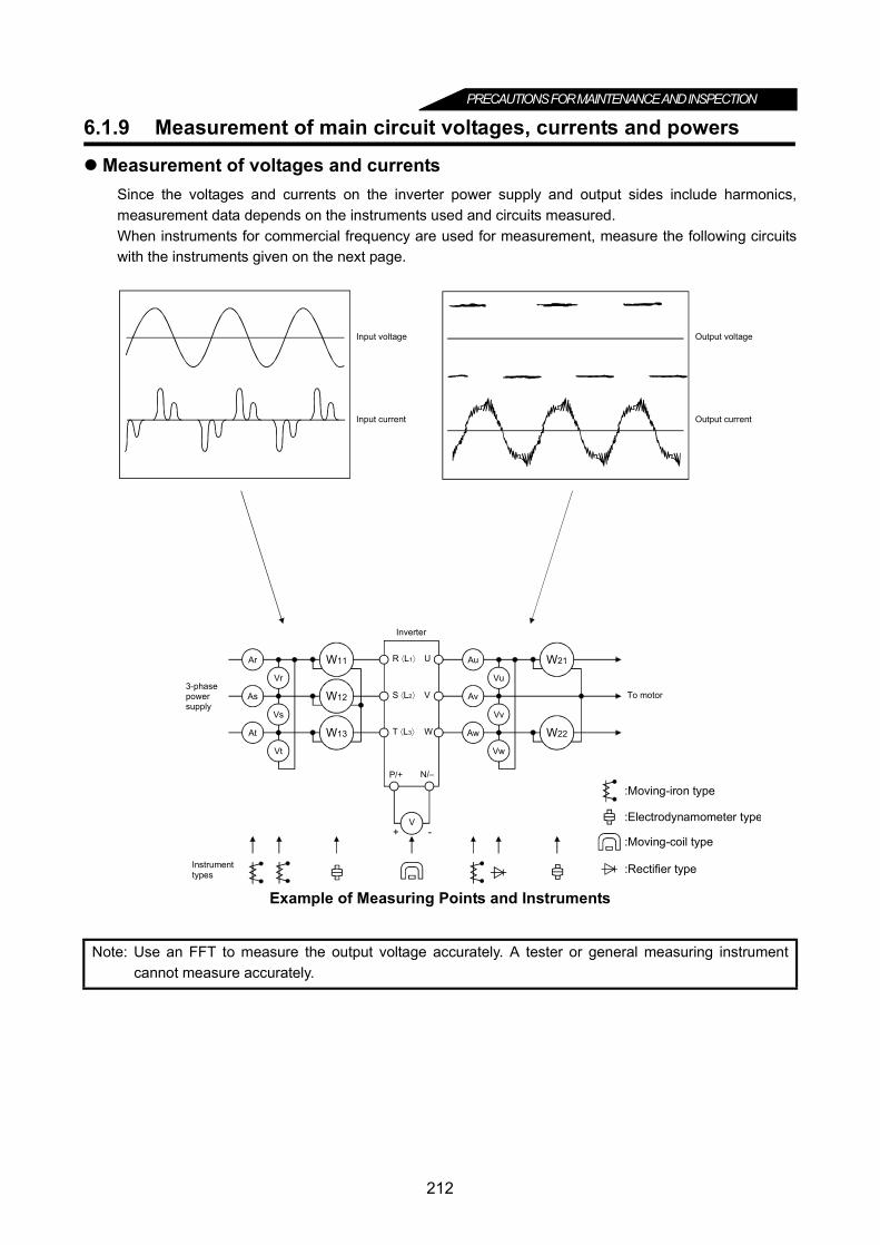
PRECAUTIONS FOR MAINTENANCE AND INSPECTION
6.1.9 Measurement of main circuit voltages, currents and powers
Measurement of voltages and currentsSince the voltages and currents on the inverter power supply and output sides include harmonics,measurement data depends on the instruments used and circuits measured.When instruments for commercial frequency are used for measurement, measure the following circuitswith the instruments given on the next page.
Example of Measuring Points and Instruments
Note: Use an FFT to measure the output voltage accurately. A tester or general measuring instrumentcannot measure accurately.
+ -
Ar
As
At
Vr
Vs
Vt
W11
W12
W13
Au
Av
Aw
Vu
Vv
Vw
W21
W22
V
U
V
W
Inverter
P/+ N/–
3-phasepowersupply
Instrumenttypes
Input voltage
Input current
Output voltage
Output current
To motor
:Moving-iron type
:Electrodynamometer type
:Moving-coil type
:Rectifier type
R ⟨L1⟩
S ⟨L2⟩
T ⟨L3⟩
212

PRECAUTIONS FOR MAINTENANCE AND INSPECTION
6
Measuring Points and Instruments
Note: 1. A tester cannot measure accurately.2. When Pr. 195 "A, B, C terminal function selection" setting is positive logic.3. When the carrier frequency exceeds 5kHz, do not use the instrument since using it may increase eddy-current losses
produced in metal parts inside the instrument, leading to burnout.In this case, use an approximate effective value type instrument.
* Values in parentheses indicate those for 400V class.
Item Measuring Point Measuring Instrument Remarks(Reference Measured Value) *
Power supply voltage V1Across R-S, S-T and T-R<Across L1-L2, L2-L3 and L3-L1> Moving-iron type AC voltmeter
Commercial power supplyWithin permissible AC voltage fluctuation (Refer to page 216)
Power supply side current I1
R, S and T line currents<L1, L2 and L1 line currents> Moving-iron type AC ammeter
Power supply side power P1
At R, S and T, and across R-S, S-T and T-R<At L1, L2 and L3, and acrossL1-L2, L2-L3 and L3-L1>
Electrodynamic type single-phase wattmeter
P1 = W11 + W12 + W13
(3-wattmeter method)
Power supply side power factor Pf1
Calculate after measuring power supply voltage, power supply side current and power supply side power.
Output side voltage V2 Across U-V, V-W and W-URectifier type AC voltmeter (Note 1) (Moving-iron type cannot measure)
Difference between phases is within ±1% of maximum output voltage.
Output side current I2 U, V and W line currents Moving-iron type AC ammeter(Note 3)
Current should be equal to or less than rated inverter current. Difference between phases is 10% or lower.
Output side power P2At U, V and W, and across U-V and V-W
Electrodynamic type single-phase wattmeter
P2 = W21 + W22
2-wattmeter method (or 3-wattmeter method)
Output side power factor Pf2
Calculate in similar manner to power supply side power factor.
Converter output Across P-N <Across + and -> Moving-coil type (such as tester)
POWER lamp lit1.35 × V1
Maximum 380V (760V) during regenerative operation
Frequency setting signalAcross 2 (+) -5
Moving-coil type (Tester, etc. may be used) (Internal resistance: 50kΩ or larger)
0 to 5V/0 to 10VDC
"5" i
sco
mm
on.Across 1 (+) -5 0 to ±5V/0 to ±10VDC
Across 4 (+) -5 4 to 20mADC
Frequency setting power supply
Across 10 (+) -5 5VDCAcross 10E (+) -5 10VDC
Frequency meter signal
Across FM (+) -SD
Approximately 5VDC at maximum frequency (without frequency meter)
Pulse width T1:Adjusted by Pr.900
Pulse cycle T2: Set by Pr.55(Valid for frequency monitoring only) S
D is
com
mon
.
Across AM (+) -5Approximately 10DVC at maximum frequency (without frequency meter)
Start signalSelect signal
Across STF, STR, RH, RM, RL, JOG, RT, AU, STOP, CS (+) -SD 20 to 30VDC when open.
ON voltage: 1V or lessReset Across RES (+) -SDOutput stop Across MRS (+) -SD
Alarm signal Across A-CAcross B-C
Moving-coil type(such as tester)
Continuity check (Note 2)<At OFF> <At ON>
Across A-C: Discontinuity ContinuityAcross B-C: Continuity Discontinuity
Pf1 = × 100%P1
3 V1 × I1
Pf2 = × 100%P2
3 V2 × I2
8VDC
T1
T2
213

MEMO
214
CHAPTER 7
SPECIFICATIONSChapter 1
Chapter 2
Chapter 3
Chapter 4
Chapter 5
Chapter 6
Chapter 7
Chapter 8
This chapter provides the "specifications" of this product.Always read the instructions and other information before usingthe equipment.
7.1 Standard Specifications .......................................216
215
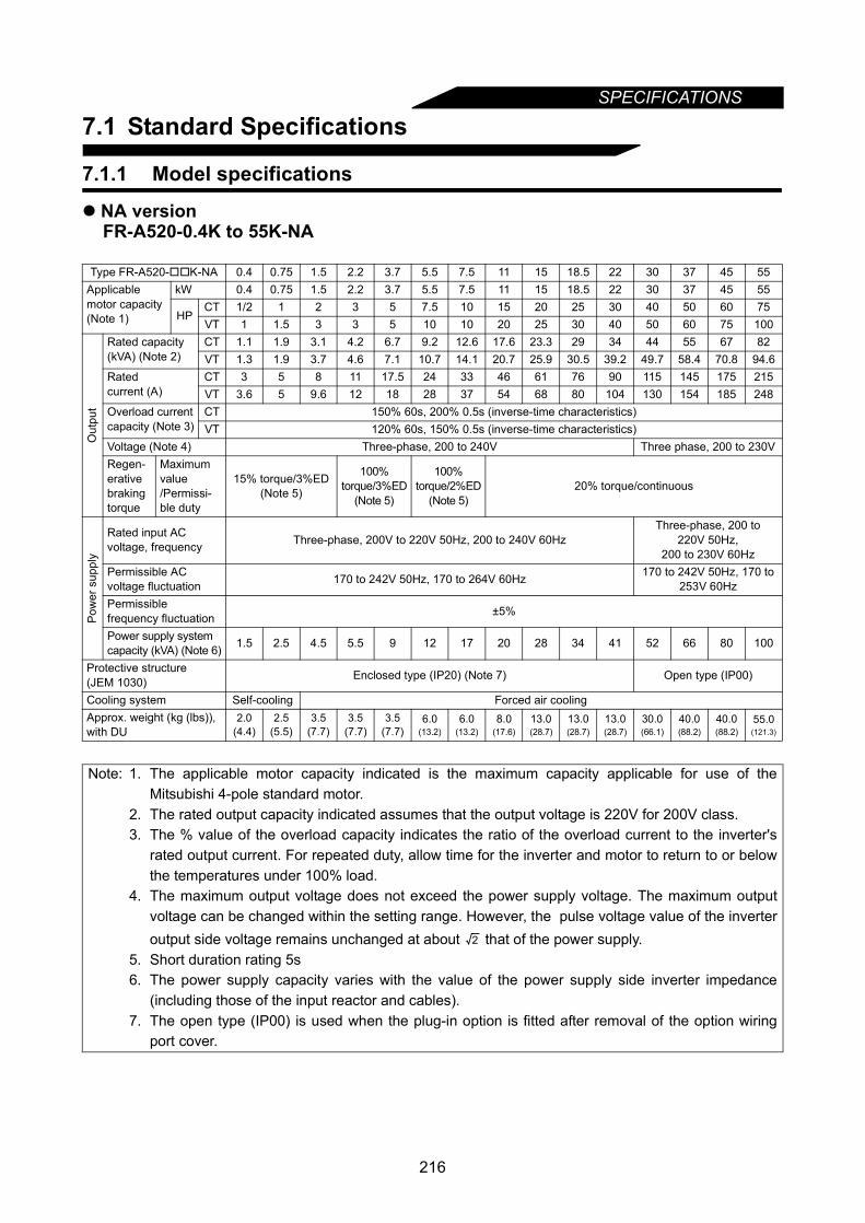
SPECIFICATIONS
7.1 Standard Specifications
7.1.1 Model specifications
NA versionFR-A520-0.4K to 55K-NA
Type FR-A520-K-NA 0.4 0.75 1.5 2.2 3.7 5.5 7.5 11 15 18.5 22 30 37 45 55Applicablemotor capacity(Note 1)
kW 0.4 0.75 1.5 2.2 3.7 5.5 7.5 11 15 18.5 22 30 37 45 55
HPCT 1/2 1 2 3 5 7.5 10 15 20 25 30 40 50 60 75VT 1 1.5 3 3 5 10 10 20 25 30 40 50 60 75 100
Out
put
Rated capacity(kVA) (Note 2)
CT 1.1 1.9 3.1 4.2 6.7 9.2 12.6 17.6 23.3 29 34 44 55 67 82VT 1.3 1.9 3.7 4.6 7.1 10.7 14.1 20.7 25.9 30.5 39.2 49.7 58.4 70.8 94.6
Ratedcurrent (A)
CT 3 5 8 11 17.5 24 33 46 61 76 90 115 145 175 215VT 3.6 5 9.6 12 18 28 37 54 68 80 104 130 154 185 248
Overload currentcapacity (Note 3)
CT 150% 60s, 200% 0.5s (inverse-time characteristics)VT 120% 60s, 150% 0.5s (inverse-time characteristics)
Voltage (Note 4) Three-phase, 200 to 240V Three phase, 200 to 230VRegen-erativebrakingtorque
Maximumvalue/Permissi-ble duty
15% torque/3%ED(Note 5)
100%torque/3%ED
(Note 5)
100%torque/2%ED
(Note 5)20% torque/continuous
Pow
er s
uppl
y
Rated input ACvoltage, frequency Three-phase, 200V to 220V 50Hz, 200 to 240V 60Hz
Three-phase, 200 to220V 50Hz,
200 to 230V 60HzPermissible ACvoltage fluctuation 170 to 242V 50Hz, 170 to 264V 60Hz 170 to 242V 50Hz, 170 to
253V 60HzPermissiblefrequency fluctuation ±5%
Power supply systemcapacity (kVA) (Note 6) 1.5 2.5 4.5 5.5 9 12 17 20 28 34 41 52 66 80 100
Protective structure(JEM 1030) Enclosed type (IP20) (Note 7) Open type (IP00)
Cooling system Self-cooling Forced air coolingApprox. weight (kg (lbs)),with DU
2.0(4.4)
2.5(5.5)
3.5(7.7)
3.5(7.7)
3.5(7.7)
6.0(13.2)
6.0(13.2)
8.0(17.6)
13.0(28.7)
13.0(28.7)
13.0(28.7)
30.0(66.1)
40.0(88.2)
40.0(88.2)
55.0(121.3)
Note: 1. The applicable motor capacity indicated is the maximum capacity applicable for use of theMitsubishi 4-pole standard motor.
2. The rated output capacity indicated assumes that the output voltage is 220V for 200V class.3. The % value of the overload capacity indicates the ratio of the overload current to the inverter's
rated output current. For repeated duty, allow time for the inverter and motor to return to or belowthe temperatures under 100% load.
4. The maximum output voltage does not exceed the power supply voltage. The maximum outputvoltage can be changed within the setting range. However, the pulse voltage value of the inverteroutput side voltage remains unchanged at about that of the power supply.
5. Short duration rating 5s6. The power supply capacity varies with the value of the power supply side inverter impedance
(including those of the input reactor and cables).7. The open type (IP00) is used when the plug-in option is fitted after removal of the option wiring
port cover.
2
216
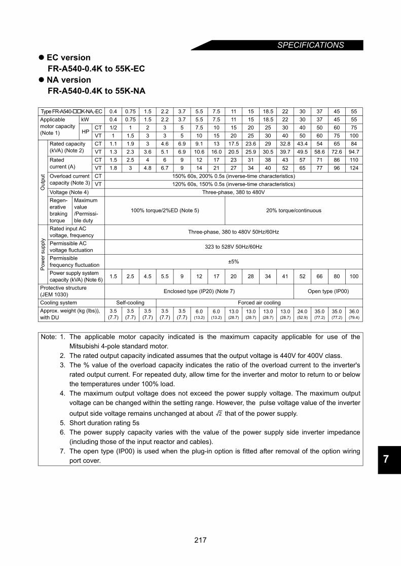
SPECIFICATIONS
7
EC versionFR-A540-0.4K to 55K-EC
NA versionFR-A540-0.4K to 55K-NA
Type FR-A540-K-NA,-EC 0.4 0.75 1.5 2.2 3.7 5.5 7.5 11 15 18.5 22 30 37 45 55Applicablemotor capacity(Note 1)
kW 0.4 0.75 1.5 2.2 3.7 5.5 7.5 11 15 18.5 22 30 37 45 55
HPCT 1/2 1 2 3 5 7.5 10 15 20 25 30 40 50 60 75VT 1 1.5 3 3 5 10 15 20 25 30 40 50 60 75 100
Out
put
Rated capacity(kVA) (Note 2)
CT 1.1 1.9 3 4.6 6.9 9.1 13 17.5 23.6 29 32.8 43.4 54 65 84VT 1.3 2.3 3.6 5.1 6.9 10.6 16.0 20.5 25.9 30.5 39.7 49.5 58.6 72.6 94.7
Ratedcurrent (A)
CT 1.5 2.5 4 6 9 12 17 23 31 38 43 57 71 86 110VT 1.8 3 4.8 6.7 9 14 21 27 34 40 52 65 77 96 124
Overload currentcapacity (Note 3)
CT 150% 60s, 200% 0.5s (inverse-time characteristics)VT 120% 60s, 150% 0.5s (inverse-time characteristics)
Voltage (Note 4) Three-phase, 380 to 480VRegen-erativebrakingtorque
Maximumvalue/Permissi-ble duty
100% torque/2%ED (Note 5) 20% torque/continuous
Pow
er s
uppl
y
Rated input ACvoltage, frequency Three-phase, 380 to 480V 50Hz/60Hz
Permissible ACvoltage fluctuation 323 to 528V 50Hz/60Hz
Permissiblefrequency fluctuation ±5%
Power supply systemcapacity (kVA) (Note 6) 1.5 2.5 4.5 5.5 9 12 17 20 28 34 41 52 66 80 100
Protective structure(JEM 1030) Enclosed type (IP20) (Note 7) Open type (IP00)
Cooling system Self-cooling Forced air coolingApprox. weight (kg (lbs)),with DU
3.5(7.7)
3.5(7.7)
3.5(7.7)
3.5(7.7)
3.5(7.7)
6.0(13.2)
6.0(13.2)
13.0(28.7)
13.0(28.7)
13.0(28.7)
13.0(28.7)
24.0(52.9)
35.0(77.2)
35.0(77.2)
36.0(79.4)
Note: 1. The applicable motor capacity indicated is the maximum capacity applicable for use of theMitsubishi 4-pole standard motor.
2. The rated output capacity indicated assumes that the output voltage is 440V for 400V class.3. The % value of the overload capacity indicates the ratio of the overload current to the inverter's
rated output current. For repeated duty, allow time for the inverter and motor to return to or belowthe temperatures under 100% load.
4. The maximum output voltage does not exceed the power supply voltage. The maximum outputvoltage can be changed within the setting range. However, the pulse voltage value of the inverteroutput side voltage remains unchanged at about that of the power supply.
5. Short duration rating 5s6. The power supply capacity varies with the value of the power supply side inverter impedance
(including those of the input reactor and cables).7. The open type (IP00) is used when the plug-in option is fitted after removal of the option wiring
port cover.
2
217
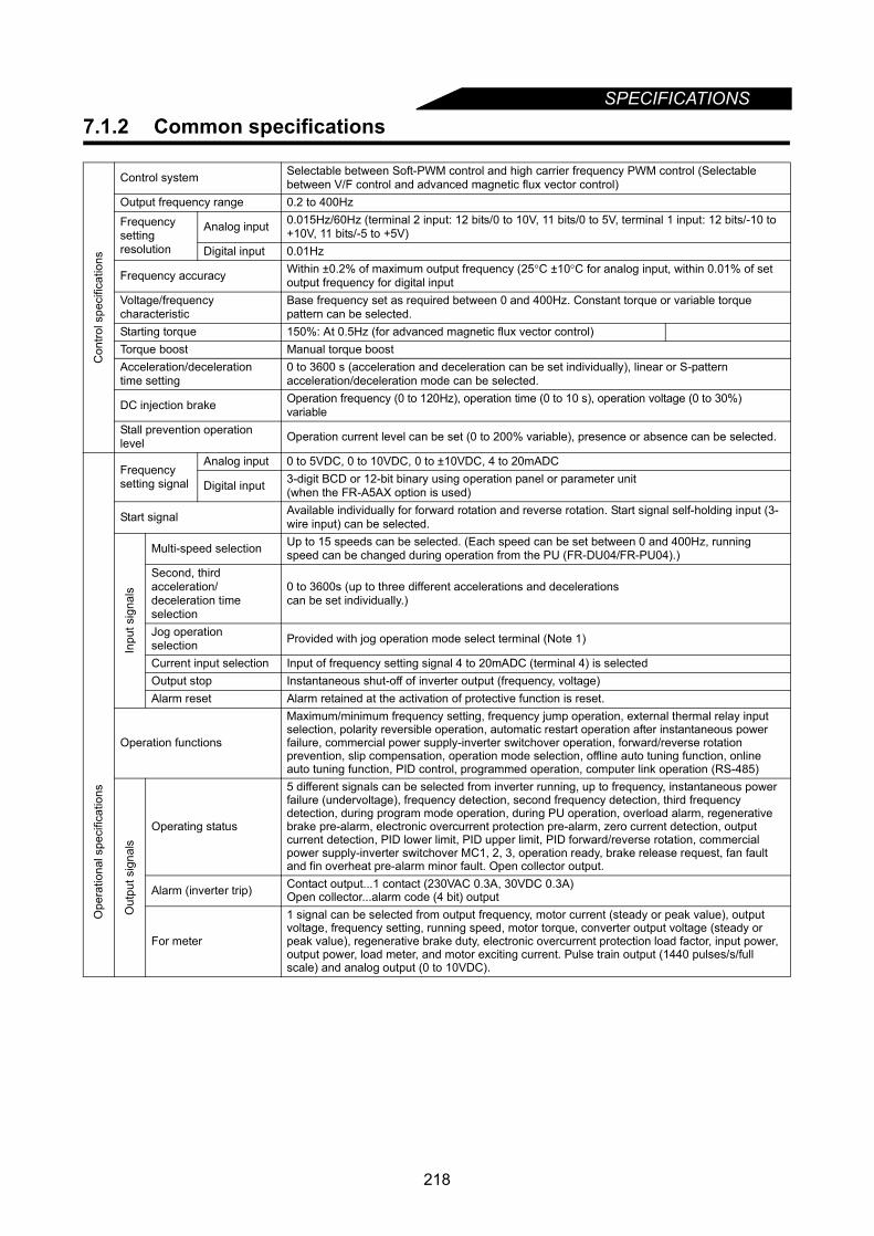
SPECIFICATIONS
7.1.2 Common specificationsCon
trol s
peci
ficat
ions
Control system Selectable between Soft-PWM control and high carrier frequency PWM control (Selectable between V/F control and advanced magnetic flux vector control)
Output frequency range 0.2 to 400Hz
Frequency setting resolution
Analog input 0.015Hz/60Hz (terminal 2 input: 12 bits/0 to 10V, 11 bits/0 to 5V, terminal 1 input: 12 bits/-10 to +10V, 11 bits/-5 to +5V)
Digital input 0.01Hz
Frequency accuracy Within ±0.2% of maximum output frequency (25°C ±10°C for analog input, within 0.01% of set output frequency for digital input
Voltage/frequency characteristic
Base frequency set as required between 0 and 400Hz. Constant torque or variable torque pattern can be selected.
Starting torque 150%: At 0.5Hz (for advanced magnetic flux vector control)Torque boost Manual torque boostAcceleration/deceleration time setting
0 to 3600 s (acceleration and deceleration can be set individually), linear or S-pattern acceleration/deceleration mode can be selected.
DC injection brake Operation frequency (0 to 120Hz), operation time (0 to 10 s), operation voltage (0 to 30%) variable
Stall prevention operation level Operation current level can be set (0 to 200% variable), presence or absence can be selected.
O
pera
tiona
l spe
cific
atio
ns
Frequency setting signal
Analog input 0 to 5VDC, 0 to 10VDC, 0 to ±10VDC, 4 to 20mADC
Digital input 3-digit BCD or 12-bit binary using operation panel or parameter unit(when the FR-A5AX option is used)
Start signal Available individually for forward rotation and reverse rotation. Start signal self-holding input (3-wire input) can be selected.
Inpu
t sig
nals
Multi-speed selection Up to 15 speeds can be selected. (Each speed can be set between 0 and 400Hz, running speed can be changed during operation from the PU (FR-DU04/FR-PU04).)
Second, third acceleration/deceleration time selection
0 to 3600s (up to three different accelerations and decelerationscan be set individually.)
Jog operationselection Provided with jog operation mode select terminal (Note 1)
Current input selection Input of frequency setting signal 4 to 20mADC (terminal 4) is selectedOutput stop Instantaneous shut-off of inverter output (frequency, voltage)Alarm reset Alarm retained at the activation of protective function is reset.
Operation functions
Maximum/minimum frequency setting, frequency jump operation, external thermal relay input selection, polarity reversible operation, automatic restart operation after instantaneous power failure, commercial power supply-inverter switchover operation, forward/reverse rotation prevention, slip compensation, operation mode selection, offline auto tuning function, online auto tuning function, PID control, programmed operation, computer link operation (RS-485)
Out
put s
igna
ls
Operating status
5 different signals can be selected from inverter running, up to frequency, instantaneous power failure (undervoltage), frequency detection, second frequency detection, third frequency detection, during program mode operation, during PU operation, overload alarm, regenerative brake pre-alarm, electronic overcurrent protection pre-alarm, zero current detection, output current detection, PID lower limit, PID upper limit, PID forward/reverse rotation, commercial power supply-inverter switchover MC1, 2, 3, operation ready, brake release request, fan fault and fin overheat pre-alarm minor fault. Open collector output.
Alarm (inverter trip) Contact output...1 contact (230VAC 0.3A, 30VDC 0.3A)Open collector...alarm code (4 bit) output
For meter
1 signal can be selected from output frequency, motor current (steady or peak value), output voltage, frequency setting, running speed, motor torque, converter output voltage (steady or peak value), regenerative brake duty, electronic overcurrent protection load factor, input power, output power, load meter, and motor exciting current. Pulse train output (1440 pulses/s/full scale) and analog output (0 to 10VDC).
218
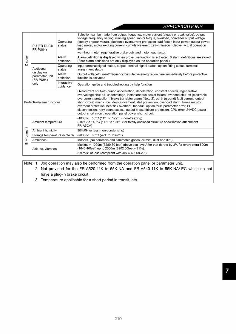
SPECIFICATIONS
7
Dis
play
PU (FR-DU04/FR-PU04)
Operating status
Selection can be made from output frequency, motor current (steady or peak value), output voltage, frequency setting, running speed, motor torque, overload, converter output voltage (steady or peak value), electronic overcurrent protection load factor, input power, output power, load meter, motor exciting current, cumulative energization timecumulative, actual operation time, watt-hour meter, regenerative brake duty and motor load factor.
Alarm definition
Alarm definition is displayed when protective function is activated. 8 alarm definitions are stored.(Four alarm definitions are only displayed on the operation panel.)
Additional display on parameter unit (FR-PU04)only
Operating status
Input terminal signal states, output terminal signal states, option fitting status, terminal assignment status
Alarm definition
Output voltage/current/frequency/cumulative energization time immediately before protective function is activated
Interactive guidance Operation guide and troubleshooting by help function
Protective/alarm functions
Overcurrent shut-off (during acceleration, deceleration, constant speed), regenerative overvoltage shut-off, undervoltage, instantaneous power failure, overload shut-off (electronic overcurrent protection), brake transistor alarm (Note 2), earth (ground) fault current, output short circuit, main circuit device overheat, stall prevention, overload alarm, brake resistor overheat protection, heatsink overheat, fan fault, option fault, parameter error, PU disconnection, retry count excess, output phase failure protection, CPU error, 24VDC power output short circuit, operation panel power short circuit
Env
ironm
ent
Ambient temperature-10°C to +50°C (14°F to 122°F) (non-freezing)(-10°C to +40°C (14°F to 104°F) for totally enclosed structure specification attachment FR-A5CV)
Ambient humidity 90%RH or less (non-condensing)Storage temperature (Note 3) -20°C to +65°C (-4°F to +149°F)Ambience Indoors. (No corrosive and flammable gases, oil mist, dust and dirt.)
Altitude, vibrationMaximum 1000m (3280.80 feet) above sea levelAfter that derate by 3% for every extra 500m (1640.40feet) up to 2500m (8202.00feet) (91%).5.9 m/s2 or less (compliant with JIS C 60068-2-6)
Note: 1. Jog operation may also be performed from the operation panel or parameter unit.2. Not provided for the FR-A520-11K to 55K-NA and FR-A540-11K to 55K-NA/-EC which do not
have a plug-in brake circuit.3. Temperature applicable for a short period in transit, etc.
219
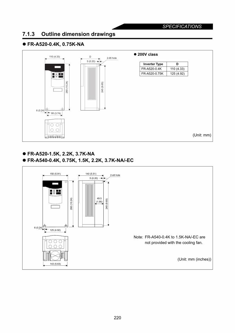
SPECIFICATIONS
7.1.3 Outline dimension drawingsFR-A520-0.4K, 0.75K-NA
FR-A520-1.5K, 2.2K, 3.7K-NA FR-A540-0.4K, 0.75K, 1.5K, 2.2K, 3.7K-NA/-EC
200V class
(Unit: mm)
Note: FR-A540-0.4K to 1.5K-NA/-EC are not provided with the cooling fan.
(Unit: mm (inches))
2-φ6 hole110 (4.33)
26
0 (
10
.24
)
95 (3.74)
6 (0.24)
5 (0.20)
245 (
9.6
5)
D
Inverter Type DFR-A520-0.4K 110 (4.33)FR-A520-0.75K 125 (4.92)
2- 6 holeφ150 (5.91)
260
(10.
24)
140 (5.51)
143 (5.63)
125 (4.92)6 (0.24)
5 (0.20)
245
(9.6
5)49.5(1.95)
220
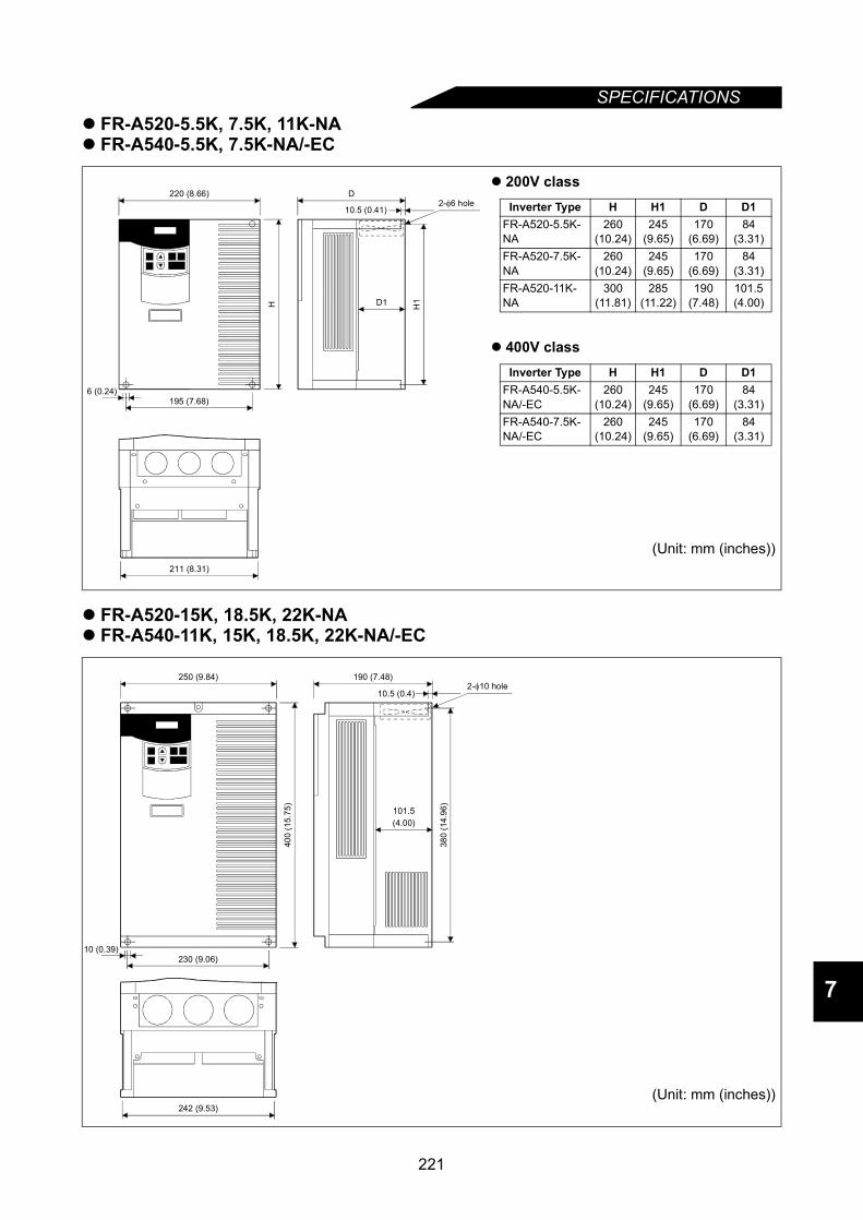
SPECIFICATIONS
7
FR-A520-5.5K, 7.5K, 11K-NA FR-A540-5.5K, 7.5K-NA/-EC
FR-A520-15K, 18.5K, 22K-NA FR-A540-11K, 15K, 18.5K, 22K-NA/-EC
200V class
400V class
(Unit: mm (inches))
(Unit: mm (inches))
H
D
H1D1
2-φ6 hole220 (8.66)
211 (8.31)
195 (7.68)6 (0.24)
10.5 (0.41) Inverter Type H H1 D D1FR-A520-5.5K-NA
260(10.24)
245(9.65)
170(6.69)
84(3.31)
FR-A520-7.5K-NA
260(10.24)
245(9.65)
170(6.69)
84(3.31)
FR-A520-11K-NA
300(11.81)
285(11.22)
190(7.48)
101.5(4.00)
Inverter Type H H1 D D1FR-A540-5.5K-NA/-EC
260(10.24)
245(9.65)
170(6.69)
84(3.31)
FR-A540-7.5K-NA/-EC
260(10.24)
245(9.65)
170(6.69)
84(3.31)
2-φ10 hole250 (9.84)
400
(15.
75)
190 (7.48)
242 (9.53)
230 (9.06)
380
(14.
96)
101.5 (4.00)
10.5 (0.4)
10 (0.39)
221

SPECIFICATIONS
FR-A520-30K, 37K, 45K, 55K-NAFR-A540-30K, 37K, 45K, 55K-NA/-EC
200V class
400V class
(Unit: mm (inches))
D1
W2
CW1
H
W D
H1
2-φC holeH2 3.2 (0.13)
Inverter Type W W1 W2 H H1 H2 D D1 C
FR-A520-30K-NA 340(13.39)
270(10.63)
320(12.60)
550(21.65)
530(20.87)
10(0.39)
195(7.68)
71.5(2.81)
10(0.39)
FR-A520-37K-NA 450(17.72)
380(14.96)
430(16.93)
550(21.65)
525(20.67)
15(0.59)
250(9.84)
154(6.06)
12(0.47)
FR-A520-45K-NA 450(17.72)
380(14.96)
430(16.93)
550(21.65)
525(20.67)
15(0.59)
250(9.84)
154(6.06)
12(0.47)
FR-A520-55K-NA 480(18.90)
410(16.14)
460(18.11)
700(27.56)
675(26.57)
15(0.59)
250(9.84)
154(6.06)
12(0.47)
Inverter Type W W1 W2 H H1 H2 D D1 C
FR-A540-30K-NA/-EC 340(13.39)
270(10.63)
320(12.60)
550(21.65)
530(20.87)
10(0.39)
195(7.68)
71.5(2.81)
10(0.39)
FR-A540-37K-NA/-EC 450(17.72)
380(14.96)
430(16.93)
550(21.65)
525(20.67)
15(0.59)
250(9.84)
154(6.06)
12(0.47)
FR-A540-45K-NA/-EC 450(17.72)
380(14.96)
430(16.93)
550(21.65)
525(20.67)
15(0.59)
250(9.84)
154(6.06)
12(0.47)
FR-A540-55K-NA/-EC 450(17.72)
380(14.96)
430(16.93)
550(21.65)
525(20.67)
15(0.59)
250(9.84)
154(6.06)
12(0.47)
222
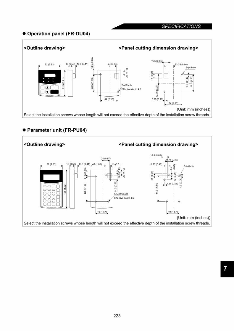
SPECIFICATIONS
7
Operation panel (FR-DU04)
Parameter unit (FR-PU04)
<Outline drawing> <Panel cutting dimension drawing>
(Unit: mm (inches))Select the installation screws whose length will not exceed the effective depth of the installation screw threads.
<Outline drawing> <Panel cutting dimension drawing>
(Unit: mm (inches))Select the installation screws whose length will not exceed the effective depth of the installation screw threads.
2-M3 hole
Effective depth 4.5
2- 4 holeφ
19.7
5 (0
.78)
3.25 (0.13)
16.5 (0.65)23.75 (0.94)
46.5
(1.8
3)
17 (0
.67)
54 (2.13)
81.5
(3.2
1)72 (2.83) 15 (0.59) 10.5 (0.41)
20 (0
.79)
54 (2.13)
16.5
(0.6
5)46
.5 (1
.83)
24 (0.94)
3.5
(0.1
4)
5-M3 threads
Effective depth 4.5
5- 4 hole
125
(4.9
2)
72 (2.83) 15 (0.59) 10.5 (0.41)
40 (1.57)
80 (3
.15)
48 (1.89)
24 (0.97)
13 (0.51)
20 (0
.79)
21.5
(0.8
5)
14.5
(0.5
7)
40 (1.57)
11.75 (0.46)
81.5
(3.2
1)
17 (0
.67)
16.5 (0.65)
1.5
(0.0
6)
18.5
(0.7
3)
23.75 (0.93)
1.25 (0.05)
1.5
(0.0
6)13
(0.5
1)
223

MEMO
224

CHAPTER 8
OPTIONSChapter 1
Chapter 2
Chapter 3
Chapter 4
Chapter 5
Chapter 6
Chapter 7
Chapter 8
This chapter explains the "options" for use of this product.Always read the instructions and other information before usingthe equipment.
8.1 Option List ...........................................................226
225
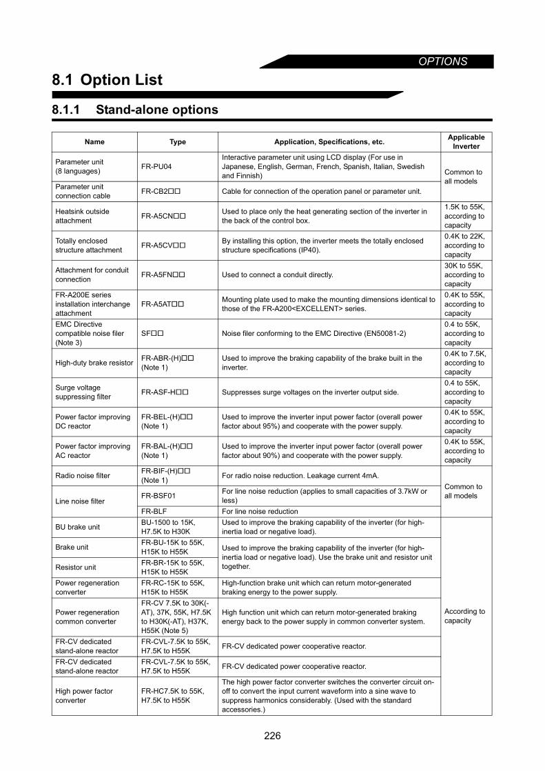
OPTIONS
8.1 Option List
8.1.1 Stand-alone options
Name Type Application, Specifications, etc. Applicable Inverter
Parameter unit(8 languages) FR-PU04
Interactive parameter unit using LCD display (For use in Japanese, English, German, French, Spanish, Italian, Swedish and Finnish) Common to
all modelsParameter unit connection cable FR-CB2 Cable for connection of the operation panel or parameter unit.
Heatsink outside attachment FR-A5CN
Used to place only the heat generating section of the inverter in the back of the control box.
1.5K to 55K, according to capacity
Totally enclosed structure attachment FR-A5CV
By installing this option, the inverter meets the totally enclosed structure specifications (IP40).
0.4K to 22K, according to capacity
Attachment for conduit connection FR-A5FN Used to connect a conduit directly.
30K to 55K, according to capacity
FR-A200E series installation interchange attachment
FR-A5ATMounting plate used to make the mounting dimensions identical to those of the FR-A200<EXCELLENT> series.
0.4K to 55K, according to capacity
EMC Directive compatible noise filer (Note 3)
SF Noise filer conforming to the EMC Directive (EN50081-2) 0.4 to 55K, according to capacity
High-duty brake resistor FR-ABR-(H)
(Note 1)Used to improve the braking capability of the brake built in the inverter.
0.4K to 7.5K, according to capacity
Surge voltage suppressing filter FR-ASF-H Suppresses surge voltages on the inverter output side.
0.4 to 55K, according to capacity
Power factor improving DC reactor
FR-BEL-(H)
(Note 1)Used to improve the inverter input power factor (overall power factor about 95%) and cooperate with the power supply.
0.4K to 55K, according to capacity
Power factor improving AC reactor
FR-BAL-(H)
(Note 1)Used to improve the inverter input power factor (overall power factor about 90%) and cooperate with the power supply.
0.4K to 55K, according to capacity
Radio noise filter FR-BIF-(H)
(Note 1) For radio noise reduction. Leakage current 4mA.Common to all models
Line noise filterFR-BSF01 For line noise reduction (applies to small capacities of 3.7kW or
less)FR-BLF For line noise reduction
BU brake unit BU-1500 to 15K, H7.5K to H30K
Used to improve the braking capability of the inverter (for high-inertia load or negative load).
According to capacity
Brake unit FR-BU-15K to 55K, H15K to H55K Used to improve the braking capability of the inverter (for high-
inertia load or negative load). Use the brake unit and resistor unit together.Resistor unit FR-BR-15K to 55K,
H15K to H55KPower regeneration converter
FR-RC-15K to 55K, H15K to H55K
High-function brake unit which can return motor-generated braking energy to the power supply.
Power regeneration common converter
FR-CV 7.5K to 30K(-AT), 37K, 55K, H7.5K to H30K(-AT), H37K, H55K (Note 5)
High function unit which can return motor-generated braking energy back to the power supply in common converter system.
FR-CV dedicated stand-alone reactor
FR-CVL-7.5K to 55K, H7.5K to H55K FR-CV dedicated power cooperative reactor.
FR-CV dedicatedstand-alone reactor
FR-CVL-7.5K to 55K, H7.5K to H55K FR-CV dedicated power cooperative reactor.
High power factor converter
FR-HC7.5K to 55K, H7.5K to H55K
The high power factor converter switches the converter circuit on-off to convert the input current waveform into a sine wave to suppress harmonics considerably. (Used with the standard accessories.)
226
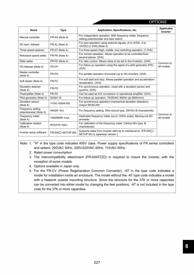
OPTIONS
8
Manual controller FR-AX (Note 4) For independent operation. With frequency meter, frequency setting potentiometer and start switch.
Common to all models
DC tach. follower FR-AL (Note 4) For joint operation using external signals. (0 to 5VDC, 0 to 10VDC) (1.5VA) (Note 2)
Three speed selector FR-AT (Note 4) For three-speed (high, middle, low) switching operation. (1.5VA)
Motorized speed setter FR-FK (Note 4) For remote operation. Allows operation to be controlled from several places. (5VA)
Ratio setter FR-FH (Note 4) For ratio control. Allows ratios to be set to five inverters. (3VA)
PG follower (Note 4) FR-FP For follow-up operation using the signal of a pilot generator (PG). (2VA)
Master controller (Note 4) FR-FG For parallel operation of several (up to 35) inverters. (5VA)
Soft starter (Note 4) FR-FC For soft start and stop. Allows parallel operation and acceleration/deceleration. (3VA)
Deviation detector (Note 4) FR-FD For synchronous operation. Used with a deviation sensor and
synchro. (5VA)Preamplifier (Note 4) FR-FA Can be used as A/V conversion or operational amplifier. (3VA)Pilot generator (Note 4) QVAH-10 For follow-up operation. 70/35VAC 500Hz (at 2500r/min)
Common to all models
Deviation sensor (Note 4) YVGC-500W-NS For synchronous operation (mechanical deviation detection).
Output 90VAC/90°Frequency setting potentiometer (Note 4) WA2W 1kΩ For frequency setting. Wire-wound type. 2W1KΩ B characteristic.
Frequency meter (Note 4) YM206NRI 1mA Dedicated frequency meter (up to 120Hz scale). Moving-coil DC
ammeter.Calibration resistor (Note 4) RV24YN 10kΩ For calibration of the frequency meter. Carbon-film type. B
characteristic.
Inverter setup software FR-SW -SETUP-WE Supports steps from inverter start-up to maintenance. (FR-SW -SETUP-WJ is Japanese version.)
Note: 1. "H" in the type code indicates 400V class. Power supply specifications of FR series controllersand setters: 200VAC 50Hz, 200V/220VAC 60Hz, 115VAC 60Hz.
2. Rated power consumption3. The intercompatibility attachment (FR-A5AT) is required to mount the inverter, with the
exception of some models.4. Options available in Japan only.5. For the FR-CV (Power Regeneration Common Converter), -AT in the type code indicates a
model for installation inside an enclosure. The model without the -AT type code indicates a modelwith a heatsink outside mounting structure. Since the structure for the 37K or more capacitiescan be converted into either model by changing the feet positions, -AT is not included in the typecode for the 37K or more capacities.
Name Type Application, Specifications, etc. Applicable Inverter
227
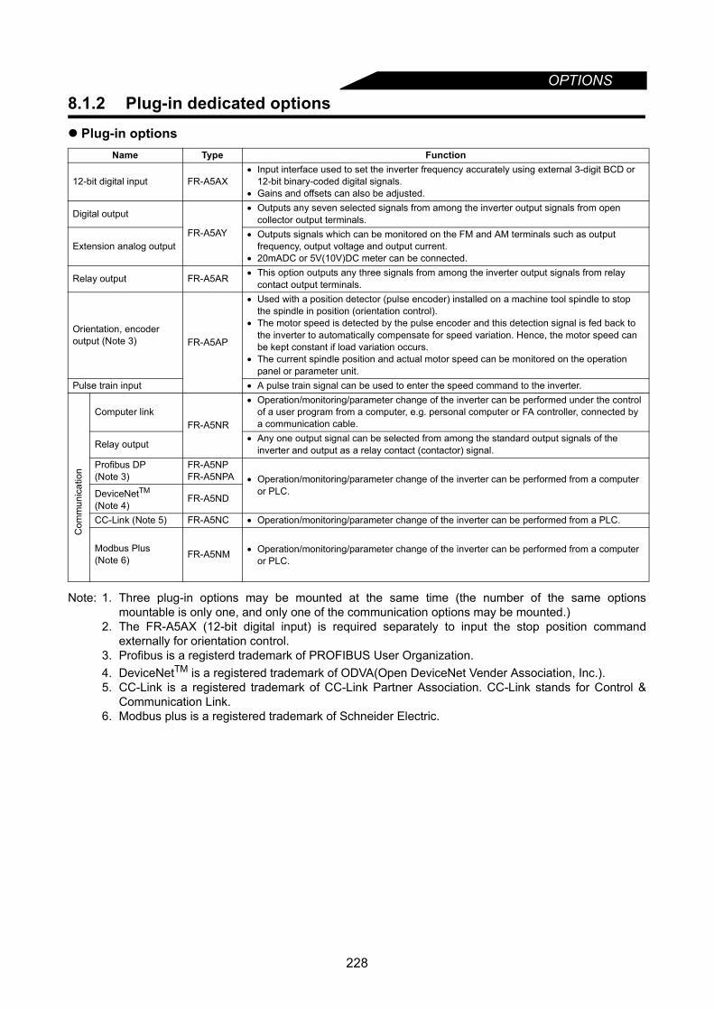
OPTIONS
8.1.2 Plug-in dedicated optionsPlug-in options
Note: 1. Three plug-in options may be mounted at the same time (the number of the same optionsmountable is only one, and only one of the communication options may be mounted.)
2. The FR-A5AX (12-bit digital input) is required separately to input the stop position commandexternally for orientation control.
3. Profibus is a registerd trademark of PROFIBUS User Organization.4. DeviceNetTM is a registered trademark of ODVA(Open DeviceNet Vender Association, Inc.).5. CC-Link is a registered trademark of CC-Link Partner Association. CC-Link stands for Control &
Communication Link.6. Modbus plus is a registered trademark of Schneider Electric.
Name Type Function
12-bit digital input FR-A5AX• Input interface used to set the inverter frequency accurately using external 3-digit BCD or
12-bit binary-coded digital signals.• Gains and offsets can also be adjusted.
Digital output
FR-A5AY
• Outputs any seven selected signals from among the inverter output signals from open collector output terminals.
Extension analog output• Outputs signals which can be monitored on the FM and AM terminals such as output
frequency, output voltage and output current.• 20mADC or 5V(10V)DC meter can be connected.
Relay output FR-A5AR • This option outputs any three signals from among the inverter output signals from relay contact output terminals.
Orientation, encoder output (Note 3) FR-A5AP
• Used with a position detector (pulse encoder) installed on a machine tool spindle to stop the spindle in position (orientation control).
• The motor speed is detected by the pulse encoder and this detection signal is fed back to the inverter to automatically compensate for speed variation. Hence, the motor speed can be kept constant if load variation occurs.
• The current spindle position and actual motor speed can be monitored on the operation panel or parameter unit.
Pulse train input • A pulse train signal can be used to enter the speed command to the inverter.
Com
mun
icat
ion
Computer linkFR-A5NR
• Operation/monitoring/parameter change of the inverter can be performed under the control of a user program from a computer, e.g. personal computer or FA controller, connected by a communication cable.
Relay output • Any one output signal can be selected from among the standard output signals of the inverter and output as a relay contact (contactor) signal.
Profibus DP(Note 3)
FR-A5NPFR-A5NPA • Operation/monitoring/parameter change of the inverter can be performed from a computer
or PLC.DeviceNetTM
(Note 4)FR-A5ND
CC-Link (Note 5) FR-A5NC • Operation/monitoring/parameter change of the inverter can be performed from a PLC.
Modbus Plus (Note 6) FR-A5NM • Operation/monitoring/parameter change of the inverter can be performed from a computer
or PLC.
228

OPTIONS
8
<When used with the FR-A5AP option>
(1) Addition of Pr. 285 "excessive speed deviation detection frequency"
In case the motor speed is increased or decreased due to load, etc. during vector control and can not becontrolled to meet the speed command value, alarm stop occurs (E. OSD).
(2) Addition of Pr. 376 "wire break detection selection"
Alarm stop (E.ECT) occurs if the encoder signal's interruption is detected during orientation, encoderfeedback or vector control.
Parameter Number Name Setting
RangeMinimum Setting
Increments Factory Setting Description
285 Excessive speed deviation detection frequency
0 to 30Hz,9999 0.01Hz 9999 9999: Not detected
CAUTIONPr. 285 shares the function with Pr. 285 "overspeed detection frequency" of the
inverter's brake sequence function. This function is made valid when vector control is selected in Pr. 370 "control mode selection".
Parameter Number Name Setting
RangeMinimum Setting
Increments Factory Setting Description
376 Wire break detection selection 0,1 1 0 0: Function invalid
1: Function valid
Note: When an encoder is connected, setting "6" in Pr. 52 makes the running speed monitor value equivalent to the actual speed. Convert |(Actual speed) - (speed command value)| into frequency.
Preset frequency
Alarm stop occurs if speed deviation becomes greater than frequency set in Pr. 285.Alarm "E.OSD" results in alarm stop.
Run
ning
spe
ed (N
ote)
Time
Actual speed
Speed command value
E.OSD activated timing|(Actual speed) - (speed command value) | > (Pr. 285)
229

OPTIONS
<When used with communication options >About of the setting values "10, 12, 20, 22" to Pr. 340 "link startup mode selection"
1) Switching between the PU operation mode and network operation mode is enabled. When Pr.340="10 or 12" and Pr.79="0 or 6", operation can be switched between the PU operation andnetwork operation from the operation panel (FR-DU04) or parameter unit (FR-PU04).• FR-DU04
Shifts to the PU operation mode when is displayed on the operation mode switching menu and
shifts to the network operation when is displayed.• FR-PU04
Shifts to the PU operation mode when the key is pressed and to the network operation mode when
the key is pressed.2) Switching between the external operation mode and network operation mode by the external terminal
(Addition of the setting of "66" to Pr.180 to 186 "input terminal function selection")When "20 or 22" is set in Pr.340 "link start up mode selection", switching between external operation andnetwork operation can be performed by the external terminal.
3) Switching between link start up mode and operation modeThe inverter starts up in the network operation mode at power-on.
Setting Signal Name Function
66 X66 Signal for switching between external operation and network operationX66-OFF : external operation mode, X66-ON : network operation mode
Note: 1. "66" can be set even when the setting values of Pr.340 "link start up mode selection" are otherthan "20 and 22" or when a communication option is not connected. However, operation can notbe switched by the X66 signal.
2. For the X66 signal, operation only from the external terminal is valid independently of the settingof Pr.338 "operation command source", Pr.339 "speed command source" (can not be operatedfrom the network).
Pr.340 Setting
Operation Mode Mode at Power On or at Restoration from Instantaneous Power Failure
Pr.79
10,12(*1)
0 PU or network operation
Inverter operates in the network operation mode.Operation mode can be switched between the PU operation and the network operation.
1 PU operation Inverter operates in the PU operation mode.
2 Network operation Inverter operates in the network operation mode.
3External/PU combined operation
Running frequency is set in the PU operation mode and the start signal is set in the external operation mode.
4External/PU combined operation
Running frequency is set in the external operation mode and the start signal is set in the PU operation mode.
5 Programmed operation Inverter operates in the programmed operation mode.
6 Switch-over Inverter operates in the network operation mode.Operation mode can be switched between the PU operation and the network operation.
7(*2) PU operation interlock
X12 signal ON Inverter operates in the external operation mode. (Operation mode can be switched to the PU operation mode by the parameter unit.)
X12 signal OFF Inverter operates in the external operation mode.
8(*2)
Operation mode switch-over by the external signal
X16 signal ON Inverter operates in the external operation mode.
X16 signal OFF Inverter operates in the PU operation mode.
230

OPTIONS
8
*1 Pr.340="12, 22"The setting of "12, 22" chooses the network operation mode, which is mainly used for computer linkoperation (when the FR-A5NR is connected).
*2 The values "10, 12" set in Pr.340 are valid only when Pr.79="0, 2, 6". (When Pr.79="7, 8", the inverteroperates in the same manner as when Pr.340="0". Therefore, the inverter will not operate in the networkoperation mode at powering on.)
*3 Pr.340="20, 22" are valid only when Pr.79="0, 2, 8" (EC version only). (When Pr.79="6, 7", the inverteroperates in the same manner as when Pr.340="0" and will not operate in the network operation mode atpower on.)
*4 Pr.340="20, 22" are valid only when Pr.79="0, 2, 6, 8" (NA version only). (When Pr.79="7", the inverteroperates in the same manner as when Pr.340="0" and will not operate in the network operation mode atpower on.)
*5 When the X66 signal is not assigned to the input terminal, the inverter starts in the same operation modeas when Pr. 340="0" for Pr.340="20" and Pr.340="2" for Pr.340="22".
20, 22(*1)
0External or Network operation
X66 signal OFF Inverter operates in the network operation mode.Operation mode can be switched to the PU operation mode by the PU.
X66 signal ON Inverter operates in the network operation mode.Without X66 signal
assignment (*5)Pr.340="20" : Inverter operates in the external operation mode.Pr.340="22" : Inverter operates in the network operation mode.
1 PU operation Inverter operates in the PU operation mode.
2External or Network operation
X66 signal OFF Inverter operates in the external operation mode.X66 signal ON Inverter operates in the network operation mode.
Without X66 signal assignment (*5)
Pr.340="20" : Inverter operates in the external operation mode.Pr.340="22" : Inverter operates in the network operation mode.
3External/PU combined operation
Running frequency (speed) is set in the PU operation mode and the start signal is set in the external operation mode.
4External/PU combined operation
Running frequency (speed) is set in the external operation mode and the start signal is set in the PU operation mode.
5 Programmed operation Inverter operates in the programmed operation mode.
6(*3) Switch-over Inverter operates in the external operation mode.Operation mode can be changed without changing the operating status.
6(*4)(NA
version only)
Switch-over
X66 signal OFF Inverter operates in the external operation mode. Operation mode can be changed
without changing the operating status.X66 signal ON Inverter operates in the network
operation mode.Without X66 signal
assignment (*5)Pr.340="20" :Inverter operates in the external operation mode.Pr.340="22": Inverter operates in the network operation mode.
7(*3)(*4)
PU operation interlock
When the X12 signal is ON, the inverter operates in the external operation mode. (operation mode can be switched to the PU operation mode by the PU.)When the X12 signal is OFF, the inverter operates in the external operation mode.
8
Operation mode switch-over by the external signal
X66 signal OFF X16 signal OFF....... Inverter operates in the PU operation mode.X16 signal ON......... Inverter operates in the external operation mode.
X66 signal ON Inverter operates in the network operation mode independently of the X16 signal.
Without X66 signal assignment (*5)
X16 signal OFF...... Inverter operates in the PU operation mode.X16 signal ON........ Pr.340="20": Inverter operates in the external
operation mode.Pr.340="22": Inverter operates in the network operation mode.
Note: 1. Change of the Pr.340 setting is made valid when powering on or resetting the inverter.2. When Pr.340="0, 1, 10, 20", computer programming, which has stopped due to an
instantaneuous power failure or the like during network operation, remains stopped even if poweris recovered. When a start command is given from the network with restart enabled (Pr. 57 ≠"9999") when Pr.340="2, 12, 22", a start command during power off (including instantaneouspower failure and power failure) is stored. Therefore, the inverter resumes operation in the statebefore powering off at powering on (power restoration) again.
3. When "10, 12, 20, 22" are copied to the inverter which is not available with "10, 12, 20, 22" forPr.340, the inverter operates in the same manner as when Pr. 340="0". For operation whenPr.340="0, 1, 2", refer to the instruction manual of each communication option.
Pr.340 Setting
Operation Mode Mode at Power On or at Restoration from Instantaneous Power Failure
Pr.79
231
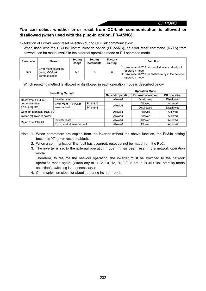
OPTIONS
You can select whether error reset from CC-Link communication is allowed ordisallowed (when used with the plug-in option, FR-A5NC).1) Addition of Pr.349 "error reset selection during CC-Link communication" When used with the CC-Link communication option (FR-A5NC), an error reset command (RY1A) fromnetwork can be made invalid in the external operation mode or PU operation mode .
Which resetting method is allowed or disallowed in each operation mode is described below.
Parameter Name Setting Range
Setting Increments
Factory Setting Function
349Error reset selection during CC-Link communication
0,1 1 0
0: Error reset (RY1A) is enabled independently of operation mode
1: Error reset (RY1A) is enabled only in the network operation mode
Resetting MethodOperation Mode
Network operation External operation PU operation
Reset from CC-Link communication (PLC program)
Inverter reset Allowed Disallowed DisallowedError reset (RY1A) at inverter fault
Pr.349=0Allowed
Allowed AllowedPr.349=1 Disallowed Disallowed
Connect terminals RES-SD Allowed Allowed AllowedSwitch off inverter power Allowed Allowed Allowed
Reset from PU/DUInverter reset Allowed Allowed AllowedError reset at inverter fault Allowed Allowed Allowed
Note: 1. When parameters are copied from the inverter without the above function, the Pr.349 settingbecomes "0" (error reset enabled).
2. When a communication line fault has occurred, reset cannot be made from the PLC.3. The inverter is set to the external operation mode if it has been reset in the network operation
mode.Therefore, to resume the network operation, the inverter must be switched to the networkoperation mode again. (When any of "1, 2, 10, 12, 20, 22" is set in Pr.340 "link start up modeselection", switching is not necessary.)
4. Communication stops for about 1s during inverter reset.
232
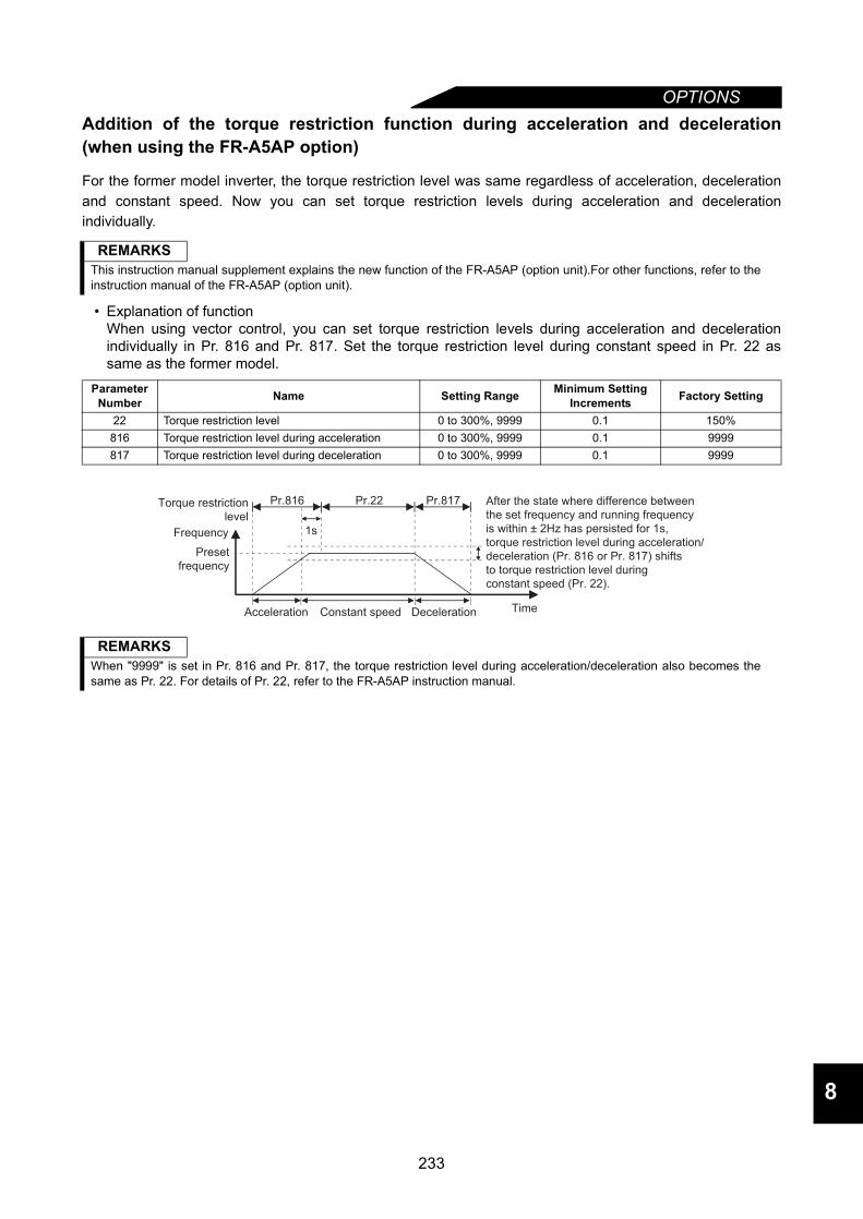
OPTIONS
8
Addition of the torque restriction function during acceleration and deceleration(when using the FR-A5AP option)
For the former model inverter, the torque restriction level was same regardless of acceleration, decelerationand constant speed. Now you can set torque restriction levels during acceleration and decelerationindividually.
• Explanation of functionWhen using vector control, you can set torque restriction levels during acceleration and decelerationindividually in Pr. 816 and Pr. 817. Set the torque restriction level during constant speed in Pr. 22 assame as the former model.
REMARKSThis instruction manual supplement explains the new function of the FR-A5AP (option unit).For other functions, refer to theinstruction manual of the FR-A5AP (option unit).
Parameter Number Name Setting Range Minimum Setting
Increments Factory Setting
22 Torque restriction level 0 to 300%, 9999 0.1 150%816 Torque restriction level during acceleration 0 to 300%, 9999 0.1 9999817 Torque restriction level during deceleration 0 to 300%, 9999 0.1 9999
REMARKSWhen "9999" is set in Pr. 816 and Pr. 817, the torque restriction level during acceleration/deceleration also becomes thesame as Pr. 22. For details of Pr. 22, refer to the FR-A5AP instruction manual.
After the state where difference between
the set frequency and running frequency
is within ± 2Hz has persisted for 1s,
torque restriction level during acceleration/
deceleration (Pr. 816 or Pr. 817) shifts
to torque restriction level during
constant speed (Pr. 22).
Acceleration Constant speed Deceleration
1s
Pr.816 Pr.22 Pr.817
Preset
frequency
Frequency
Time
Torque restriction
level
233
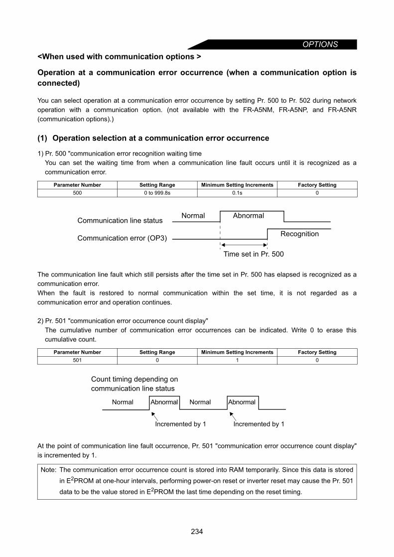
OPTIONS
<When used with communication options >Operation at a communication error occurrence (when a communication option isconnected)
You can select operation at a communication error occurrence by setting Pr. 500 to Pr. 502 during networkoperation with a communication option. (not available with the FR-A5NM, FR-A5NP, and FR-A5NR(communication options).)
(1) Operation selection at a communication error occurrence
1) Pr. 500 "communication error recognition waiting timeYou can set the waiting time from when a communication line fault occurs until it is recognized as acommunication error.
The communication line fault which still persists after the time set in Pr. 500 has elapsed is recognized as acommunication error.When the fault is restored to normal communication within the set time, it is not regarded as acommunication error and operation continues.
2) Pr. 501 "communication error occurrence count display"The cumulative number of communication error occurrences can be indicated. Write 0 to erase thiscumulative count.
At the point of communication line fault occurrence, Pr. 501 "communication error occurrence count display"is incremented by 1.
Parameter Number Setting Range Minimum Setting Increments Factory Setting500 0 to 999.8s 0.1s 0
Parameter Number Setting Range Minimum Setting Increments Factory Setting501 0 1 0
Note: The communication error occurrence count is stored into RAM temporarily. Since this data is stored
in E2PROM at one-hour intervals, performing power-on reset or inverter reset may cause the Pr. 501
data to be the value stored in E2PROM the last time depending on the reset timing.
Normal AbnormalCommunication line status
Communication error (OP3) Recognition
Time set in Pr. 500
Count timing depending oncommunication line status
Abnormal Abnormal Normal Normal
Incremented by 1 Incremented by 1
234

OPTIONS
8
3) Pr. 502 "communication error-time stop mode selection"You can select the inverter operation if a communication line fault or a fault of the option itself occurs.
About settings
• At fault occurrence
*If the fault status returns to the normal communication status within the time set in Pr. 500, a communicationline fault (E, OP3) dose not occur.
Parameter Number Setting Range Minimum Setting Increments Factory Setting502 0, 1, 2 1 0
Fault Pr. 502 Setting
At Fault Occurrence Error Recognition after Elapse of Pr. 500 Time At Fault Removal
Operation Indication Alarm output Operation Indication Alarm
output Operation Indication Alarm output
Com
mun
icat
ion
line
0
ContinuedNormal
indication(*)
Not provided
(*)
Coast to stop E.OP3 lit Provided
Kept stopped
E.OP3 kept lit Provided
1Decelerated
to stopE.OP3 lit after stop
Provided after stop
2 Not provided Restart Normal
indicationNot
Provided
Plu
g-in
opt
ion
itsel
f
0 Coast to stop E. 3 lit Provided Coast to
stop E. 3 lit Provided
Kept stopped E. 3kept lit Provided
1,2 Decelerated to stop
E. 3 lit after stop
Provided after stop
Decelerated to stop
E. 3 lit after stop
Provided after stop
REMARKS1. A communication line fault [E.OP3 (alarm data: HA3)] is a fault that occurs on the communication line, and a fault of
the option itself [E. 3 (alarm data: HF3)] is a communication circuit fault in the communication option.2. The alarm output is the ABC contact output or alarm bit output.3. When the setting was made to provide an alarm output, the fault definition is stored into the alarm history. (The fault
definition is written to the alarm history when an alarm output is provided.) When no alarm output is provided, the faultdefinition overwrites the alarm indication of the alarm history temporarily, but is not stored. After the fault is removed,the alarm indication is reset and returns to the ordinary monitor, and the alarm history returns to the preceding alarmindication.
4. When the Pr. 502 setting is 1 or 2, the deceleration time is the ordinary deceleration setting (e.g. Pr. 8, Pr. 44, Pr. 45,Pr. 111).
5. The acceleration time at a restart is the ordinary acceleration setting (e.g. Pr. 7, Pr. 44, Pr. 110).6. When the Pr. 502 setting is 2, the operation/speed command at a restart is the one given before the fault occurrence.7. When a communication line fault occurs at the Pr. 502 setting of 2, removing the fault during deceleration causes
acceleration to restart at that point. (Acceleration is not restarted if the fault is that of the option itself.)
235
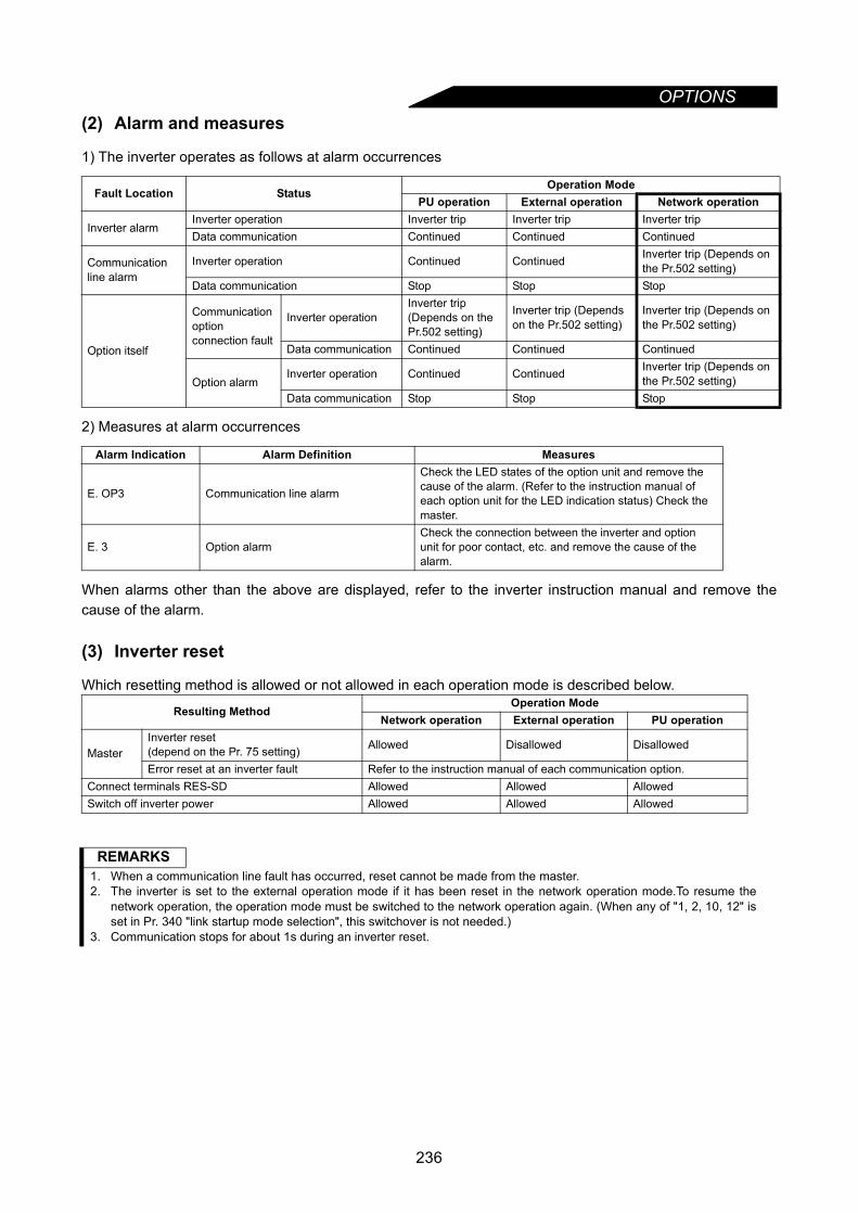
OPTIONS
(2) Alarm and measures1) The inverter operates as follows at alarm occurrences
2) Measures at alarm occurrences
When alarms other than the above are displayed, refer to the inverter instruction manual and remove thecause of the alarm.
(3) Inverter reset
Which resetting method is allowed or not allowed in each operation mode is described below.
Fault Location StatusOperation Mode
PU operation External operation Network operation
Inverter alarmInverter operation Inverter trip Inverter trip Inverter tripData communication Continued Continued Continued
Communication line alarm
Inverter operation Continued Continued Inverter trip (Depends on the Pr.502 setting)
Data communication Stop Stop Stop
Option itself
Communication option connection fault
Inverter operationInverter trip (Depends on the Pr.502 setting)
Inverter trip (Depends on the Pr.502 setting)
Inverter trip (Depends on the Pr.502 setting)
Data communication Continued Continued Continued
Option alarmInverter operation Continued Continued Inverter trip (Depends on
the Pr.502 setting)Data communication Stop Stop Stop
Alarm Indication Alarm Definition Measures
E. OP3 Communication line alarm
Check the LED states of the option unit and remove the cause of the alarm. (Refer to the instruction manual of each option unit for the LED indication status) Check the master.
E. 3 Option alarmCheck the connection between the inverter and option unit for poor contact, etc. and remove the cause of the alarm.
Resulting MethodOperation Mode
Network operation External operation PU operation
MasterInverter reset (depend on the Pr. 75 setting) Allowed Disallowed Disallowed
Error reset at an inverter fault Refer to the instruction manual of each communication option.Connect terminals RES-SD Allowed Allowed AllowedSwitch off inverter power Allowed Allowed Allowed
REMARKS1. When a communication line fault has occurred, reset cannot be made from the master.2. The inverter is set to the external operation mode if it has been reset in the network operation mode.To resume the
network operation, the operation mode must be switched to the network operation again. (When any of "1, 2, 10, 12" isset in Pr. 340 "link startup mode selection", this switchover is not needed.)
3. Communication stops for about 1s during an inverter reset.
236

OPTIONS
8
<When used with the FR-A5ND (DeviceNet) option>
The methods of setting DeviceNet node address and baud rate using FR-DU04 or FR-PU04 are shown asfollows.
Remarks: Parameter copy, parameter clear and all parameter clear are enabled.
Bitmap parameters
Note: When using the FR-PU04, you need not set the Pr. 347 and Pr. 348 values. These parameter valuesare automatically changed by setting the Pr. 345 and Pr. 346 values.
Parameter Number Name Setting
Range
Minimum Setting
Increments
Factory Setting Description
345 DeviceNet address starting data 0 to 65519 1 41023(63)
( ) forFR-DU04
346 DeviceNet baud rate starting data 0 to 65519 1 20612(132)
( ) forFR-DU04
347 DeviceNet address starting data(higher-order byte) 0 to 255 1 160
348 DeviceNet baud rate starting data(higher-order byte) 0 to 255 1 80
15 14 13 12 11 10 9 8 7
Address key
6 5 4 3 2 1 0
Device node address
bit
6 57 4 3 2 1 001234567bit
7 6 5 4 3 2 1 0 7 6 5 4 3 2 1 0
Pr. 347 (Note )
15 14 13 12 11 10
001234567bit
FR-DU04
FR-PU04
FR-PU04
option
9 8 7 6 5 4 3 2 1 0
Input assembly Output assemblyBaud rate key
Pr. 346 and Pr. 348 are bitmap parameters and defined as follows:
bit 7 6 5 4 3 2 1 0FR-DU04
01234567
7 6 5 4 3 2 1
Pr. 345 and Pr. 347 are bitmap parameters and defined as follows:
Baud rate
Watchdog time-out
actionDN fault
mode
option
Pr. 345
Pr. 345Pr. 347
Pr. 348 (Note )Pr. 346
Pr. 346Pr. 348
237

MEMO
238
This chapter explains the "appendices" for use of thisproduct.Always read the instructions and other information beforeusing the equipment.
Appendix1 Instruction Code List .....................................240Appendix2 Operating the Inverter Using a Single-Phase
Power Supply .................................................247
239
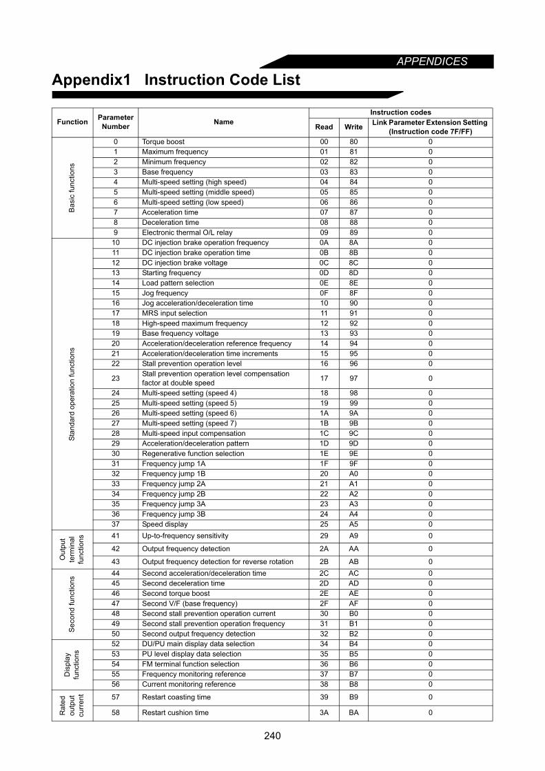
APPENDICES
Appendix1 Instruction Code List
Function Parameter Number Name
Instruction codes
Read Write Link Parameter Extension Setting (Instruction code 7F/FF)
Bas
ic fu
nctio
ns
0 Torque boost 00 80 01 Maximum frequency 01 81 02 Minimum frequency 02 82 03 Base frequency 03 83 04 Multi-speed setting (high speed) 04 84 05 Multi-speed setting (middle speed) 05 85 06 Multi-speed setting (low speed) 06 86 07 Acceleration time 07 87 08 Deceleration time 08 88 09 Electronic thermal O/L relay 09 89 0
Stan
dard
ope
ratio
n fu
nctio
ns
10 DC injection brake operation frequency 0A 8A 011 DC injection brake operation time 0B 8B 012 DC injection brake voltage 0C 8C 013 Starting frequency 0D 8D 014 Load pattern selection 0E 8E 015 Jog frequency 0F 8F 016 Jog acceleration/deceleration time 10 90 017 MRS input selection 11 91 018 High-speed maximum frequency 12 92 019 Base frequency voltage 13 93 020 Acceleration/deceleration reference frequency 14 94 021 Acceleration/deceleration time increments 15 95 022 Stall prevention operation level 16 96 0
23 Stall prevention operation level compensation factor at double speed 17 97 0
24 Multi-speed setting (speed 4) 18 98 025 Multi-speed setting (speed 5) 19 99 026 Multi-speed setting (speed 6) 1A 9A 027 Multi-speed setting (speed 7) 1B 9B 028 Multi-speed input compensation 1C 9C 029 Acceleration/deceleration pattern 1D 9D 030 Regenerative function selection 1E 9E 031 Frequency jump 1A 1F 9F 032 Frequency jump 1B 20 A0 033 Frequency jump 2A 21 A1 034 Frequency jump 2B 22 A2 035 Frequency jump 3A 23 A3 036 Frequency jump 3B 24 A4 037 Speed display 25 A5 0
Out
put
term
inal
func
tions 41 Up-to-frequency sensitivity 29 A9 0
42 Output frequency detection 2A AA 0
43 Output frequency detection for reverse rotation 2B AB 0
Sec
ond
func
tions
44 Second acceleration/deceleration time 2C AC 045 Second deceleration time 2D AD 046 Second torque boost 2E AE 047 Second V/F (base frequency) 2F AF 048 Second stall prevention operation current 30 B0 049 Second stall prevention operation frequency 31 B1 050 Second output frequency detection 32 B2 0
Dis
play
func
tions
52 DU/PU main display data selection 34 B4 053 PU level display data selection 35 B5 054 FM terminal function selection 36 B6 055 Frequency monitoring reference 37 B7 056 Current monitoring reference 38 B8 0
Rat
edou
tput
curr
ent 57 Restart coasting time 39 B9 0
58 Restart cushion time 3A BA 0
240

APPENDICES
Additi
onal
func
tion
59 Remote setting function selection 3B BB 0
Ope
ratio
n se
lect
ion
func
tions
60 Intelligent mode selection 3C BC 061 Reference I for intelligent mode 3D BD 062 Ref. I for intelligent mode accel 3E BE 063 Ref. I for intelligent mode decel 3F BF 064 Starting frequency for elevator mode 40 C0 065 Retry selection 41 C1 0
66 Stall prevention operation level reduction starting frequency 42 C2 0
67 Number of retries at alarm occurrence 43 C3 068 Retry waiting time 44 C4 069 Retry count display erasure 45 C5 070 Special regenerative brake duty 46 C6 071 Applied motor 47 C7 072 PWM frequency selection 48 C8 073 0-5V/0-10V selection 49 C9 074 Filter time constant 4A CA 0
75 Reset selection/disconnected PU detection/PU stop selection 4B CB 0
76 Alarm code output selection 4C CC 0
77 Parameter write disable selection 4D CD (Note) 0
78 Reverse rotation prevention selection 4E CE 0
79 Operation mode selection 4F CF (Note) 0
Adv
ance
d m
agne
tic fl
ux v
ecto
rcon
trol 80 Motor capacity 50 D0 0
81 Number of motor poles 51 D1 082 Motor excitation current 52 D2 083 Rated motor voltage 53 D3 084 Rated motor frequency 54 D4 089 Speed control gain 59 D9 090 Motor constant (R1) 5A DA 091 Motor constant (R2) 5B DB 092 Motor constant (L1) 5C DC 093 Motor constant (L2) 5D DD 094 Motor constant (X) 5E DE 095 Online auto tuning selection 5F DF 096 Auto-tuning setting/status 60 E0 0
5-po
int f
lexi
ble
V/F
char
acte
ristic
s
100 V/F1 (first frequency) 00 80 1101 V/F1 (first frequency voltage) 01 81 1102 V/F2 (second frequency) 02 82 1103 V/F2 (second frequency voltage) 03 83 1104 V/F3 (third frequency) 04 84 1105 V/F3 (third frequency voltage) 05 85 1106 V/F4 (fourth frequency) 06 86 1107 V/F4 (fourth frequency voltage) 07 87 1108 V/F5 (fifth frequency) 08 88 1109 V/F5 (fifth frequency voltage) 09 89 1
Third
func
tions
110 Third acceleration/deceleration time 0A 8A 1111 Third deceleration time 0B 8B 1112 Third torque boost 0C 8C 1113 Third V/F (base frequency) 0D 8D 1114 Third stall prevention operation current 0E 8E 1115 Third stall prevention operation frequency 0F 8F 1116 Third output frequency detection 10 90 1
Function Parameter Number Name
Instruction codes
Read Write Link Parameter Extension Setting (Instruction code 7F/FF)
241

APPENDICES
Comm
unic
atio
nfu
nctio
ns
117 Communication station number 11 91 1118 Communication speed 12 92 1119 Stop bit length/data length 13 93 1120 Parity check presence/absence 14 94 1121 Number of communication retries 15 95 1122 Communication check time interval 16 96 1123 Waiting time setting 17 97 1124 CR, LF presence/absence selection 18 98 1
PID
con
trol
128 PID action selection 1C 9C 1129 PID proportional band 1D 9D 1130 PID integral time 1E 9E 1131 Upper limit 1F 9F 1132 Lower limit 20 A0 1133 PID action set point for PU operation 21 A1 1134 PID differential time 22 A2 1
Com
mer
cial
pow
ersu
pply
-inve
rter
switc
hove
r
135 Commercial power supply-inverter switchover sequence output terminal selection 23 A3 1
136 MC switchover interlock time 24 A4 1137 Start waiting time 25 A5 1
138 Commercial power supply-inverter switchover selection at alarm occurrence 26 A6 1
139 Automatic inverter-commercial power supply switchover frequency 27 A7 1
Bac
klas
h 140 Backlash acceleration stopping frequency 28 A8 1141 Backlash acceleration stopping time 29 A9 1142 Backlash deceleration stopping frequency 2A AA 1143 Backlash deceleration stopping time 2B AB 1
Display144 Speed setting switchover 2C AC 1145 PU display language selection 2D AD 1
Additionalfunctions
148 Stall prevention operation level at 0V input 30 B0 1149 Stall prevention operation level at 10V input 31 B1 1150 Output current detection level 32 B2 1151 Output current detection period 33 B3 1152 Zero current detection level 34 B4 1153 Zero current detection period 35 B5 1
Sub
func
tions 154 Voltage reduction selection during stall prevention
operation 36 B6 1
155 RT signal activated condition 37 B7 1156 Stall prevention operation selection 38 B8 1157 OL signal waiting time 39 B9 1158 AM terminal function selection 3A BA 1
Additionalfunction 160 User group read selection 00 80 2
Res
tart
afte
rin
stan
tane
ous
pow
er fa
ilure 162 Automatic restart after instantaneous power failure
selection 02 82 2
163 First cushion time for restart 03 83 2164 First cushion voltage for restart 04 84 2165 Restart stall prevention operation level 05 85 2
Initial monitor
170 Watt-hour meter clear 0A 8A 2171 Actual operation hour meter clear 0B 8B 2
Use
rfu
nctio
ns
173 User group 1 registration 0D 8D 2174 User group 1 deletion 0E 8E 2175 User group 2 registration 0F 8F 2176 User group 2 deletion 10 90 2
Function Parameter Number Name
Instruction codes
Read Write Link Parameter Extension Setting (Instruction code 7F/FF)
Cur
rent
de
tect
ion
242
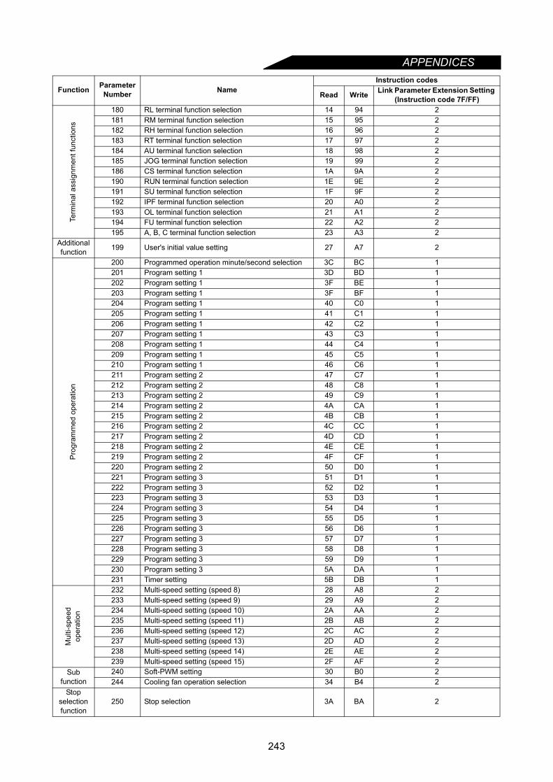
APPENDICES
Termin
al a
ssig
nmen
t fun
ctio
ns
180 RL terminal function selection 14 94 2181 RM terminal function selection 15 95 2182 RH terminal function selection 16 96 2183 RT terminal function selection 17 97 2184 AU terminal function selection 18 98 2185 JOG terminal function selection 19 99 2186 CS terminal function selection 1A 9A 2190 RUN terminal function selection 1E 9E 2191 SU terminal function selection 1F 9F 2192 IPF terminal function selection 20 A0 2193 OL terminal function selection 21 A1 2194 FU terminal function selection 22 A2 2195 A, B, C terminal function selection 23 A3 2
Additionalfunction 199 User's initial value setting 27 A7 2
Pro
gram
med
ope
ratio
n
200 Programmed operation minute/second selection 3C BC 1201 Program setting 1 3D BD 1202 Program setting 1 3F BE 1203 Program setting 1 3F BF 1204 Program setting 1 40 C0 1205 Program setting 1 41 C1 1206 Program setting 1 42 C2 1207 Program setting 1 43 C3 1208 Program setting 1 44 C4 1209 Program setting 1 45 C5 1210 Program setting 1 46 C6 1211 Program setting 2 47 C7 1212 Program setting 2 48 C8 1213 Program setting 2 49 C9 1214 Program setting 2 4A CA 1215 Program setting 2 4B CB 1216 Program setting 2 4C CC 1217 Program setting 2 4D CD 1218 Program setting 2 4E CE 1219 Program setting 2 4F CF 1220 Program setting 2 50 D0 1221 Program setting 3 51 D1 1222 Program setting 3 52 D2 1223 Program setting 3 53 D3 1224 Program setting 3 54 D4 1225 Program setting 3 55 D5 1226 Program setting 3 56 D6 1227 Program setting 3 57 D7 1228 Program setting 3 58 D8 1229 Program setting 3 59 D9 1230 Program setting 3 5A DA 1231 Timer setting 5B DB 1
Mul
ti-sp
eed
oper
atio
n
232 Multi-speed setting (speed 8) 28 A8 2233 Multi-speed setting (speed 9) 29 A9 2234 Multi-speed setting (speed 10) 2A AA 2235 Multi-speed setting (speed 11) 2B AB 2236 Multi-speed setting (speed 12) 2C AC 2237 Multi-speed setting (speed 13) 2D AD 2238 Multi-speed setting (speed 14) 2E AE 2239 Multi-speed setting (speed 15) 2F AF 2
Subfunction
240 Soft-PWM setting 30 B0 2244 Cooling fan operation selection 34 B4 2
Stopselectionfunction
250 Stop selection 3A BA 2
Function Parameter Number Name
Instruction codes
Read Write Link Parameter Extension Setting (Instruction code 7F/FF)
243
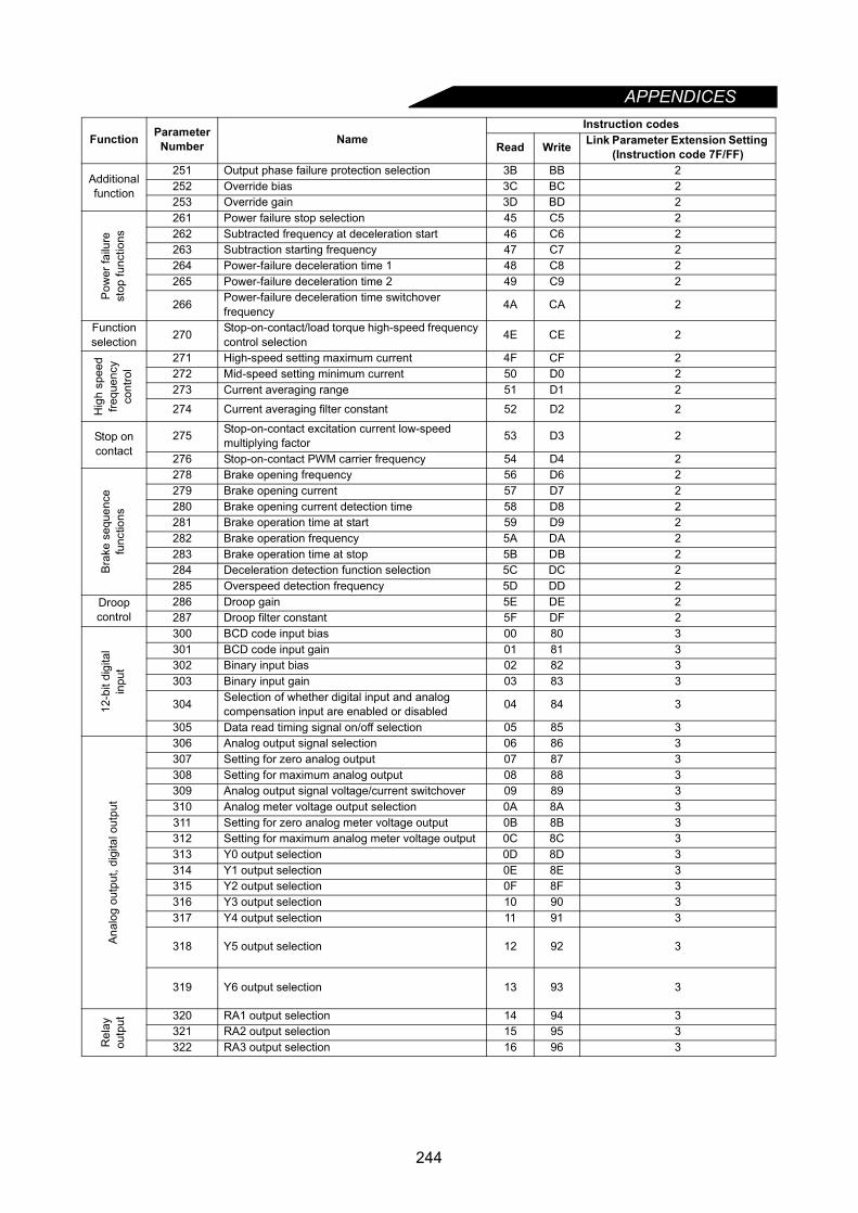
APPENDICES
Additionalfunction
251 Output phase failure protection selection 3B BB 2252 Override bias 3C BC 2253 Override gain 3D BD 2
Pow
er fa
ilure
stop
func
tions
261 Power failure stop selection 45 C5 2262 Subtracted frequency at deceleration start 46 C6 2263 Subtraction starting frequency 47 C7 2264 Power-failure deceleration time 1 48 C8 2265 Power-failure deceleration time 2 49 C9 2
266 Power-failure deceleration time switchover frequency 4A CA 2
Functionselection 270 Stop-on-contact/load torque high-speed frequency
control selection 4E CE 2
Hig
h sp
eed
frequ
ency
cont
rol
271 High-speed setting maximum current 4F CF 2272 Mid-speed setting minimum current 50 D0 2273 Current averaging range 51 D1 2
274 Current averaging filter constant 52 D2 2
Stop oncontact
275 Stop-on-contact excitation current low-speed multiplying factor 53 D3 2
276 Stop-on-contact PWM carrier frequency 54 D4 2
Bra
ke s
eque
nce
func
tions
278 Brake opening frequency 56 D6 2279 Brake opening current 57 D7 2280 Brake opening current detection time 58 D8 2281 Brake operation time at start 59 D9 2282 Brake operation frequency 5A DA 2283 Brake operation time at stop 5B DB 2284 Deceleration detection function selection 5C DC 2285 Overspeed detection frequency 5D DD 2
Droopcontrol
286 Droop gain 5E DE 2287 Droop filter constant 5F DF 2
12-b
it di
gita
lin
put
300 BCD code input bias 00 80 3301 BCD code input gain 01 81 3302 Binary input bias 02 82 3303 Binary input gain 03 83 3
304 Selection of whether digital input and analog compensation input are enabled or disabled 04 84 3
305 Data read timing signal on/off selection 05 85 3
Ana
log
outp
ut, d
igita
l out
put
306 Analog output signal selection 06 86 3307 Setting for zero analog output 07 87 3308 Setting for maximum analog output 08 88 3309 Analog output signal voltage/current switchover 09 89 3310 Analog meter voltage output selection 0A 8A 3311 Setting for zero analog meter voltage output 0B 8B 3312 Setting for maximum analog meter voltage output 0C 8C 3313 Y0 output selection 0D 8D 3314 Y1 output selection 0E 8E 3315 Y2 output selection 0F 8F 3316 Y3 output selection 10 90 3317 Y4 output selection 11 91 3
318 Y5 output selection 12 92 3
319 Y6 output selection 13 93 3
Rel
ayou
tput 320 RA1 output selection 14 94 3
321 RA2 output selection 15 95 3322 RA3 output selection 16 96 3
Function Parameter Number Name
Instruction codes
Read Write Link Parameter Extension Setting (Instruction code 7F/FF)
244

APPENDICES
Compu
ter l
ink
func
tion
330 RA output selection 1E 9E 3331 Inverter station number 1F 9F 3332 Communication speed 20 A0 3333 Stop bit length 21 A1 3334 Parity check yes/no 22 A2 3335 Communication retry count 23 A3 3336 Communication check time interval 24 A4 3337 Waiting time setting 25 A5 3338 Operation command source 26 A6 3339 Speed command source 27 A7 3340 Link startup mode selection 28 A8 3341 CR • LF yes/no selection 29 A9 3342 E2PROM write selection 2A AA 3
Dfv
iceN
et
Com
mun
icat
ion 345 DeviceNet address startup data (lower byte) 2D AD 3
346 DeviceNet baud rate startup data (lower byte ) 2E AE 3
347 DeviceNet address startup data (higher byte) 2F AF 3
348 DeviceNet baud rate startup data (higher byte) 30 B0 3
Orie
ntat
ion
cont
rol /
Enc
oder
feed
back
con
trol /
Pul
se tr
ain
inpu
t
350 Stop position command selection 32 B2 3351 Orientation switchover speed 33 B3 3352 Crreep speed 34 B4 3353 Creep switch position 35 B5 3354 Position loop switchover position 36 B6 3355 DC injection start position 37 B7 3356 Internal stop position command 38 B8 3357 In-position zone 39 B9 3358 Servo torque selection 3A BA 3359 Encoder rotation direction 3B BB 3360 12 bit date selection 3C BC 3361 Position shift 3D BD 3362 Position loop gain 3E BE 3363 Completion signal output delay time 3F BF 3364 Encoder stop check time 40 C0 3365 Orientation censored time 41 C1 3366 Reconfirmation time 42 C2 3367 Speed feedback range 43 C3 3368 Feedback gain 44 C4 3369 Number of orientation encoder pulses 45 C5 3370 Control mode selection 46 C6 3371 Torque characteristic selection 47 C7 3372 Speed control P gain 48 C8 3373 Speed control I gain 49 C9 3374 Overspeed detection level 4A CA 3375 Servo lock gain 4B CB 3376 Disconnection detection selection 4C CC 3380 Acceleration S pattern 1 50 D0 3381 Deceleration S pattern 1 51 D1 3382 Acceleration S pattern 2 52 D2 3383 Deceleration S pattern 2 53 D3 3384 Input pulse division scaling factor 54 D4 3385 Frequency for zero input pulse 55 D5 3386 Frequency for maximum input pulse 56 D6 3
Function Parameter Number Name
Instruction codes
Read Write Link Parameter Extension Setting (Instruction code 7F/FF)
245

APPENDICES
LONW
OR
KS
com
mun
icat
ion 387 Initial communication delay time 57 D7 3
388 Send time interval at hart beat 58 D8 3
389 Minimum sending time at hart beat 59 D9 3
390 % setting reference frequency 5A DA 3
391 Receive time interval at hart beat 5B DB 3
392 Event driven detection width 5C DC 3
Com
mun
icat
ion 500 Communication error recognition waiting time 00 80 5
501 Communication error occurence count display 01 81 5
502 Communication error-time stop mode selection 02 82 5
Cap
acito
rlif
e
503 Capacitor life timer 03 83 5
504 Capacitor life alarm output setting time 04 84 5
Res
tart
afte
r in
stan
tane
ous
pow
er fa
ilure
611 Restart acceleration time 0B 8B 6
Vect
orco
ntro
l 816 Acceleration torque restriction level 10 90 8
817 Deceleration torque restriction level 11 90 8
Cal
ibra
tion
func
tions
900 FM terminal calibration 5C DC 1901 AM terminal calibration 5D DD 1902 Frequency setting voltage bias 5E DE 1903 Frequency setting voltage gain 5F DF 1904 Frequency setting current bias 60 E0 1905 Frequency setting current gain 61 E1 1990 PU buzzer control 5A DA 9991 PU contrast adjustment 5B DB 9
Cal
ibra
tion
func
tions
Second parameter switchover 6C EC
Freq
uenc
yse
tting
Running frequency (RAM) 6D ED
Running frequency (E2PROM) 6E EE
Mon
itor
Frequency monitor 6F
Output current monitor 70
Output voltage monitor 71
Special monitor 72
Special monitor selection No. 73 F3
Ala
rmdi
spla
y
Most recent No. 1, No. 2/alarm display clear 74 F4
Most recent No. 3, No. 4 75
Most recent No. 5, No. 6 76
Most recent No. 7, No. 8 77
Inverter status monitor/run command 7A FA
Operation mode acquisition 7B FB
All clear FC
Inverter reset FD
Link parameter extension setting 7F FF
Note: Note that read and write to the parameters Pr. 77 and Pr. 79 are enabled for computer link operationthat uses the PU connector, but write is disabled for computer link operation that uses the option(FR-A5NR).
Function Parameter Number Name
Instruction codes
Read Write Link Parameter Extension Setting (Instruction code 7F/FF)
246

247
APPENDICES
Appendix2 Operating the Inverter Using a Single-Phase Power Supply
If a single-phase power supply is used to operate the inverter only 4 of the 6 of the diodes will be used.Therefore the ripple current of the capacitor will increase when compared to operation from a three-phasepower supply, resulting in a higher temperature rise of the converter and the capacitor. Operating the inverterusing a single-phase power supply requies derating of the output current.
• Rating for inverter operation using single-phase power supply
(Note 1) The maximum output voltage cannot exceed the power supply voltage. The maximum outputvoltage may be set as desired below supply voltage.
(Note 2) The power supply capacity changes with the values of power supply side inverter impedance(including those of the input reactor and cables).
• Cautions on operating the inverter using single-phase power supply(1) Connect the single-phase power supply to the terminals R and S of the inverter.(2) If the capacity of the power supply is insufficient, the output voltage will become unstable under
changing load conditions. Therefore, be certain the power supply is adequate.
Note: Only the NA version A500 is UL listed for the above single-phase ratings.The A500 inverter is not CE marked for single-phase operation. The A500 is not EMC compliant forsingle-phase operation.
Type FR-A520-K 0.4 0.75 1.5 2.2 3.7
Out
-pu
t
Continuous current (Constant Torque) 1.5 2.5 4 5 7
Voltage (Note 1) Three phase, 200 to 220V 50Hz, 200 to 240V 60Hz
Pow
ersu
pply
Rated input AC current (A) (Single phase) 4.5 6.4 11.2 12.9 17.4
Rated input AC voltage Single phase, 200 to 220V 50Hz, 200 to 240V 60HzPower supply system capacty (kVA) (Note 2) 1.5 2.5 4.5 5.5 9
R
S
T
U
V
W
IM
InverterNFBMotor
STF (STR)
SD Grounding
Power supplySingle phase
AC200 - 220V 50HzAC200 - 240V 60Hz
Start signal
<Example circuit>

REVISONS* The manual number is given on the bottom left of the back cover.
For Maximum Safety• Mitsubishi are not designed or manufactured to be used in equipment or systems in situations that can
affect or endanger human life.• When considering this product for operation in special applications such as machinery or systems used in
passenger transportation, medical, aerospace, atomic power, electric power, or submarine repeatingapplications, please contact your nearest Mitsubishi sales representative.
• Although this product was manufactured under conditions of strict quality control, you are strongly advisedto install safety devices to prevent serious accidents when it is used in facilities where breakdowns of theproduct are likely to cause a serious accident.
• Please do not use this product for loads other than three-phase induction motors.
Print Data *Manual Number RevisionSep., 1997 IB(NA)-66790-A First editionOct., 1997 IB(NA)-66790-B Partly modified
Front coverNov., 1997 IB(NA)-66790-C Additions
• Instructions for Standard-compliant products (pages 39, 40)• FR-A540-30K to 55KModifications• Pr. 902 to Pr. 905 <adjustment procedure>• External options• Dedicated inboard options
Mar., 1998 IB(NA)-66790-D Additions• In accordance with NA and ECModifications• In accordance with Standard-compliant models• User group setting• Input terminal function selection
Oct., 1998 IB(NA)-66790-E Additions• Description of the data line filterPartial additions• Alarm displays (E.E6, E.E7)Modifications• Change in earth (ground) terminal position of FR-A520-0.4K, 0.75K• Change in earth (ground) terminal screw size of FR-A520-5.5K, 7.5K• About RS-485/RS-232C converter
Apr., 1999 IB(NA)-66790-F Modification• Instructions for compliance with the UL and CSA standards
Jan., 2001 IB(NA)-66790-G Additions• Alarm displays (E. 1 to E. 3, E.OSD, E.ECT)• Pr. 342 "E2PROM write selection"• Instructions for fitting the FR-A5NC inboard option• Instructions for fitting the FR-A5ND inboard option.Modification• Alarm displays (E. 6, E. 7)• Instructions for compliance with U.S. and Canadian Electrical Codes
Oct., 2003 IB(NA)-66790-H Modification• Error correction
Feb., 2005 IB(NA)-66790-J Additons• Alarm output2 signal (Y94)• Instructions for using communication options• Capacitor life alarm function• Restart acceleration time