fracture caging: can we control the extent of a hydraulic ... · control comprises of efficiently...
TRANSCRIPT

PROCEEDINGS, 43rd Workshop on Geothermal Reservoir Engineering
Stanford University, Stanford, California, February 12-14, 2018
SGP-TR-213
1
Fracture Caging: Can We Control the Extent of a Hydraulic Fracture Stimulated Zone?
Luke P. Frash1, Pengcheng Fu
2, Joe Morris
2, and EGS Collab Team
3
1Los Alamos National Laboratory, PO Box 1663, Los Alamos, NM, 87545 2Lawrence Livermore National Laboratory
3Team members listed in acknowledgements
Keywords: Fracture Control, Flow Control, EGS, Stimulation, Hydraulic Fracture
ABSTRACT
One of the greatest challenges of Enhanced Geothermal Systems (EGS) is fracture control and flow control in the subsurface. Fracture
control comprises of efficiently manipulating natural fractures and stimulating new fractures to desired specifications. Flow control
comprises of optimizing fluid flow to and between wells for improved energy recovery. In this study, we investigate the potential of
using multi-spot well layouts as a means for fracture control and flow control. A central well serves as a stimulation and injection well
while a surrounding set of production wells serve as a ‘fracture cage’. All wells are drilled prior to any injection or hydraulic stimulation
with the intent of using the ‘fracture cage’ to (1) limit out-of-zone fracture growth, (2) to maximize the probability of a hydraulic
connection between the injector and one or more production wells, and (3) to recover more of the injected fluids. Statistical analysis is
used to evaluate the performance of several multi-spot well layouts in different stress and fracture regimes. Numerical modelling with
GEOS predicts that the presence of the production wells can stunt or even halt the propagation of hydraulic fractures. This research was
conducted for the design phase of the SIGMA-V geothermal project at the Sanford Underground Research Facility (SURF).
1. INTRODUCTION
Enhanced Geothermal Systems (EGS), also referred to as engineered geothermal systems, is thought to be a key to expanding
geothermal energy production to deep hot ‘dry’ rock resources (Tester et al., 2006). These unconventional geothermal resources contain
significant stored thermal energy but lack the natural fluid flow (e.g., permeability or convection) required for conventional geothermal
energy harvesting methods to be successful. Instead, flow must be anthropogenically induced through these hot rock reservoirs. Fluid
injection into one borehole, through the rock, and into other borehole(s) is one method by which to create the required flow for
geothermal energy production. Flow through the rock may be aided by hydraulically conductive fractures, especially in very low
permeability crystalline rock systems (e.g., granites). These fractures may be naturally occurring or induced by methods such as
hydraulic fracturing. With current technology, it is very difficult or impossible to predict where naturally permeable zones and fractures
are prior to drilling. Similarly, it is very difficult or impossible to predict where hydraulic fractures will be created from injection into a
given well (Valko and Economides, 1995). Therefore, a method for developing EGS that is insensitive to this significant uncertainty is
needed in order to improve the success rate of EGS projects.
We propose a ‘fracture caging’ concept to increase the likelihood of successfully recovering heat from deep hot rock systems. The
proposed method involves utilizing a multi-spot well layout that can be drilled prior to any permeability stimulation activities (e.g, fluid
injection, hydro-shearing, or hydraulic fracturing). The layout includes at least one injector and producer. Statistical analysis shows that
higher success rates for a fracture to intercept at least one injection well and one production well are anticipated when multiple
producers are drilled. Several multi-spot well layouts are considered to evaluate the fracture caging concept. Numerical modelling
predicts that, in a uniform stress field, the presence of production well(s) intercepting a propagating hydraulic fracture can stunt or even
halt fracture propagation even while injection continues at a high rate. This multi-spot well layout was proposed as a means for fracture
control in the SIGMA-V (EGS Collab) project at the Sanford Underground Research Facility (SURF) experiment site.
2. WELL LAYOUTS AND PROBABILITY OF FRACTURE-PRODUCER INTERCEPT
A requirement for EGS is to successfully establish flow through the subsurface. At a minimum, at least one hydraulically conductive
fracture must intercept both an injection well and a production well to achieve this requirement. Two options for this include: (1) using
site data to anticipate the direction that hydraulically stimulated fractures are likely to propagate and drilling a compatible well layout;
and (2) drilling and stimulating injection wells, mapping the stimulated fracture zone with methods such as microseismic monitoring,
and then drilling production wells to intercept this zone. The first option inherits risk from a lack of a-priori data about the true stress
conditions and rock structure in the subsurface. The second option inherits risk from uncertainty in locating hydraulically conductive
fractures versus those that are not conductive. Note that a combination of these two options is also practical to consider. For fracture
caging, only the first option will be considered for analysis because both the injection and production wells are drilled prior to
stimulation. We use Monte-Carlo analysis to evaluate the probability of a fracture intercepting the injector and one or more production
wells within different well layouts subjected to specified uncertainties.
2.1 Uncertainty Parameters
For this stochastic analysis, we include uncertainty regarding fracture asymmetry, radius, offset, strike, dip, and ‘scatter’ (Fig. 1). These
uncertainty terms may arise by many different phenomena with some examples as follows:

Frash et al.
2
Asymmetry can occur when local stress distribution favors fracture propagation in one direction more than others.
Radius is affected by rock elastic properties and fracture toughness, each of which have uncertainty associated with them.
Offset can occur when a hydraulic fracture initiates at an unexpected or uncertain point along the length of a well.
Strike and dip uncertainty originate from imprecision and inaccuracy in estimating principal stress directions.
Scatter in the fracture plane (i.e., undulation, roughness, and branching) can be created by the rock fabric and local weakness.
Figure 1: Independent uncertainty parameters for stochastic fracture modelling. ‘Scatter’ is included as a term to include the
effects of fracture roughness, undulation, and branching as it pertains to intersection location with another wellbore.
We use the SIGMA-V Experiment 1 site at SURF as a case study for well intercept Monte-Carlo analysis. Values for most of the
uncertainty parameters (Table 1) were obtained from hydraulic fracture measurements at the kISMET project (Oldenburg et. al, 2016)
which is located within 100 m of the SIGMA-V Experiment 1 site. Estimates for the scatter angle were evaluated using observations
from laboratory hydraulic fracture experiments in a true-triaxial apparatus (Frash et al., 2015). The scatter angle values are not a
precisely measured uncertainty term for the Experiment 1 site. A standard normal uncertainty distribution was assumed for the
asymmetry, radius, strike, dip, and scatter terms. A uniform 360° range uncertainty distribution was assumed for the direction of
asymmetry. A uniform uncertainty distribution accounting for the full length of the design packer interval (0.5 m) was used for the
offset term. Borehole azimuth and dip uncertainty were taken from drilling contract tolerance specifications.
Table 1: Uncertainty terms for the SIGMA-V Experiment 1 site.
Parameter Min. (2σ) Mean Max. (2σ) Source
Hydraulic fracture radius (distance, m) 5 15 25 Design
Hydraulic fracture scatter (angle, deg) -15 0 15 Lab
Hydraulic fracture strike (AZN, deg) 55 86 106 kISMET
Hydraulic fracture dip (down, deg) 63 78 93 kISMET
Hydraulic fracture asymmetry (radius factor, no unit) -0.8 0 0.8 Best guess
Hydraulic fracture longitudinal shift (distance, m) -0.25 0 0.25 Packer length
Borehole azimuth (Azn, deg) 2 4 6 Contract
Borehole dip (down, deg) 10 12 14 Contract
2.2 SIGMA-V Experiment 1 Site Base Case: Two-Spot Well Layout
A preliminary two-spot borehole layout proposed for the SIGMA-V Experiment 1 (Fig. 2) was analyzed to estimate the probability that
a hydraulic fracture would intercept the intended production well, the adjacent mine drift, or any of six instrumentation boreholes drilled
to monitor the experiment. All wells are drilled prior to stimulation to 60 m length in this layout. The injection well and production well
are parallel with 10 m offset. The production well also serves as a ‘guard well’ to intersect any fractures that propagate towards the drift.
Two instrumentation wells are drilled sub-parallel to the injection well with angles to position them above and below the injection well
at depth. Four additional instrumentation wells are drilled sub-orthogonal to the injection well with the intent of bounding the
stimulation zone.

Frash et al.
3
Figure 2. SIGMA-V Experiment 1 preliminary layout with three hydraulic fracture intervals (dark blue), mine drift (light blue),
one injection well (red), one production well (orange), and six instrumentation wells (grey) shown. This is a two-spot
layout with the production well drilled prior to hydraulic fracture stimulation. The kISMET boreholes are also shown.
Hydraulic fracture stimulation at 30 m and 60 m into the injection well was analyzed for this two-spot well layout (Fig. 3). A 75%
probability of the hydraulic fracture intersecting the production well (Fig. 3: ID 2) was predicted for stimulation at 30 m. A 74%
probability was predicted for stimulation at 60 m. For stimulation at 60 m, the production well extends sufficiently far beyond the
predicted mean hydraulic fracture intersection distance of 47.7 m so as to intersect most hydraulic fracture alignments. Fracture
asymmetry and radius uncertainty result in ~25% of the fractures being insufficiently long to reach the production well. This indicates
that continued stimulation in the event of no hydraulic fracture intersection could extend the fractures such that they may intersect the
production well if any asymmetry can be overcome. Note that fracture volume without leak-off can be approximated as a cubic function
of the fracture length for penny-shaped fractures (Smith and Montgomery, 2016) so an increase of injected volume by a factor of at least
8 would be necessary to extend the length of a fracture by a factor of 2.
Figure 3: Analysis of two-spot layout with hydraulic fracture initiation at (a) 30 m and (b) 60 m. For each stimulation set, the
probability of intersecting the producer is depicted (top left) as a function of required fracture length divided by realized
fracture radius to provide an indication of how much additional fracture length is may be needed to successfully
intercept the production well. Also, the distribution of intersection locations along the production well (top right) so as to
indicate whether the fractures are missing the tip of the production well and if additional production well drilled depth
would be beneficial. The probability of hydraulic fracture intersecting each hole in the layout (bottom left) is shown to
evaluate the suitability of placement for the various wells with respect to the mine drift. Example realization of fractures
within the borehole layouts are included for visualization (bottom right). Overall, a 75% probability of successfully
intercepting the production well is predicted for this two-spot layout.
This model also predicts probabilities of a hydraulic fracture intersecting the drift and/or other wells that are drilled. On one hand, this is
valuable information for risk-assessment design of these wells. On the other hand, these additional intersections reveal some challenges
associated with intersecting a planar fracture with a production well if other production well alignments had been selected. For example,
if it was decided to drill the production well at (Fig. 3: ID 5) there would be a negligible probability of intersecting the hydraulic
fracture.

Frash et al.
4
2.2 Evaluation of Alternative Layout: Three-Spot Layout
An alternative three-spot well layout was also analyzed for the SIGMA-V Experiment 1 (Fig. 4). The two production wells in this layout
are both drilled sub-parallel with the injection well from the same point in the mine drift to minimize drill rig mobilization time. These
production wells are laterally offset so that one production well is positioned between the injection well and the drift. All wells are
drilled along down-dipping alignments to aid in well fluid control during drilling and cable tool use. The injection well is 50 m long, the
production wells are 65 m long, and the instrumentation wells are 70 m long.
Figure 4: Potential three-spot layout for SIGMA-V Experiment 1. Total borehole length is reduced from 480 m to 440 m and the
number of boreholes is reduced from 8 to 7 with the intention of reducing drilling costs. A box pattern is used for the
instrumentation wells to optimize placement for microseismic monitoring spatial resolution. Multiple fracture
realizations are shown with emphasis on those that fail to intercept the western production well.
Hydraulic fracture stimulation at 30 m and 50 m into the injection well was analyzed for this three-spot well layout (Fig. 5). A 97%
probability of the hydraulic fracture intersecting a production well (Fig. 5: ID 2 or 3) was predicted for stimulation at 30 m. A 90%
probability was predicted for stimulation at 50 m. The decrease in probability of intersection at the 50 m stimulation point is primarily
caused by the increased distance between the production wells and the injection well at greater depth. As before, this problem can be
overcome by continued injection and, in this case, continued injection is a more viable option in the event of strong asymmetry because
of the additional production well. The probability of a fracture intersecting an instrumentation well is reduced with this layout unless the
fractures are extended significantly beyond the target 15 m radius.
Figure 5: Analysis of three-spot layout with hydraulic fracture initiation at (a) 30 m and (b) 50 m. Probability of fracture
intersection with at least one production well is better than 90% with this layout as compared to ~75% with the two-spot
layout. Probability of fracture intersection with an instrumentation well is decreased with this layout as long as the
fracture is close to the target design length of 15 m.
Frash et al.
5
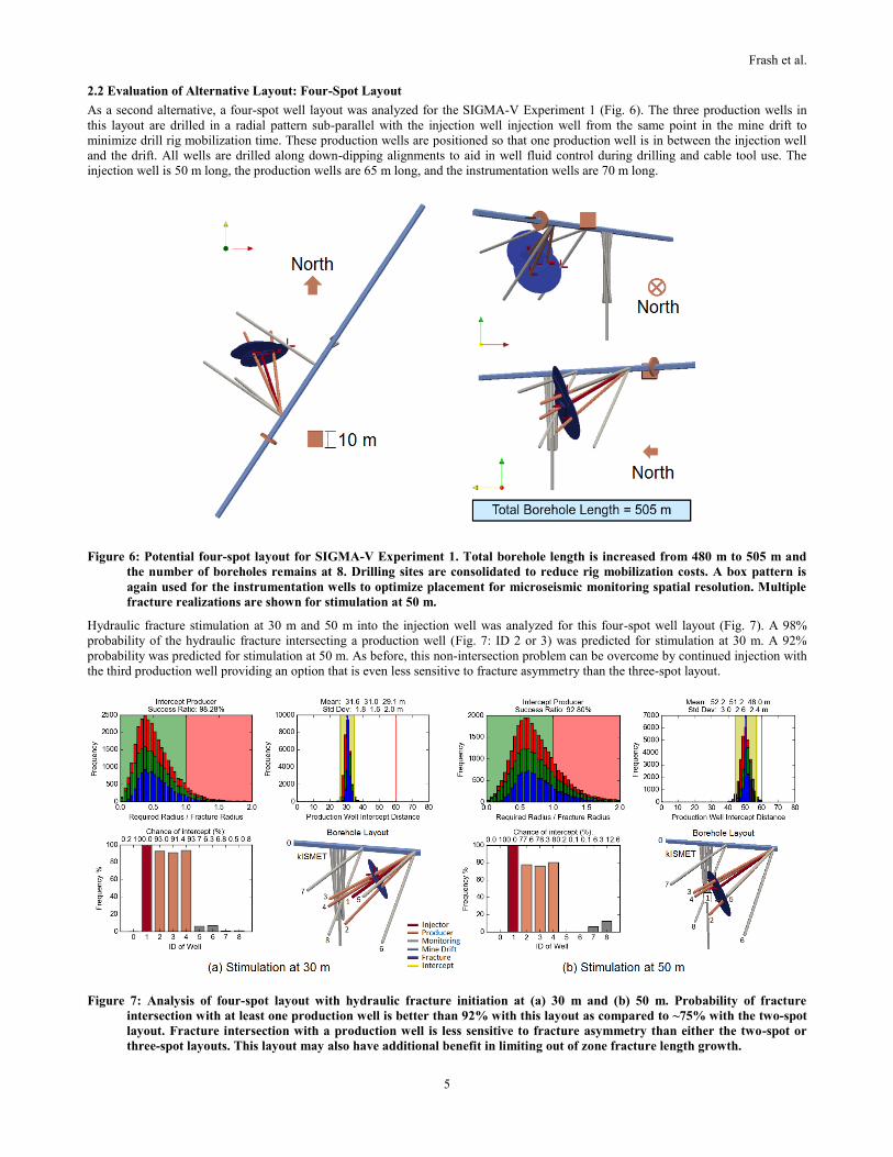
2.2 Evaluation of Alternative Layout: Four-Spot Layout
As a second alternative, a four-spot well layout was analyzed for the SIGMA-V Experiment 1 (Fig. 6). The three production wells in
this layout are drilled in a radial pattern sub-parallel with the injection well injection well from the same point in the mine drift to
minimize drill rig mobilization time. These production wells are positioned so that one production well is in between the injection well
and the drift. All wells are drilled along down-dipping alignments to aid in well fluid control during drilling and cable tool use. The
injection well is 50 m long, the production wells are 65 m long, and the instrumentation wells are 70 m long.
Figure 6: Potential four-spot layout for SIGMA-V Experiment 1. Total borehole length is increased from 480 m to 505 m and
the number of boreholes remains at 8. Drilling sites are consolidated to reduce rig mobilization costs. A box pattern is
again used for the instrumentation wells to optimize placement for microseismic monitoring spatial resolution. Multiple
fracture realizations are shown for stimulation at 50 m.
Hydraulic fracture stimulation at 30 m and 50 m into the injection well was analyzed for this four-spot well layout (Fig. 7). A 98%
probability of the hydraulic fracture intersecting a production well (Fig. 7: ID 2 or 3) was predicted for stimulation at 30 m. A 92%
probability was predicted for stimulation at 50 m. As before, this non-intersection problem can be overcome by continued injection with
the third production well providing an option that is even less sensitive to fracture asymmetry than the three-spot layout.
Figure 7: Analysis of four-spot layout with hydraulic fracture initiation at (a) 30 m and (b) 50 m. Probability of fracture
intersection with at least one production well is better than 92% with this layout as compared to ~75% with the two-spot
layout. Fracture intersection with a production well is less sensitive to fracture asymmetry than either the two-spot or
three-spot layouts. This layout may also have additional benefit in limiting out of zone fracture length growth.

Frash et al.
6
3. FRACTURE CONTAINMENT USING PRODUCTION WELLS
3.1 Model Setup
Numerical fracture propagation and flow modelling was performed using LLNL’s GEOS code (Fu et al., 2013; Settgast et al., 2017) to
evaluate how the presence of pre-drilled production wells may affect a propagating hydraulic fracture. This modelling used measured
and estimated rock and fluid parameters for the SIGMA-V Experiment 1 site at SURF (Table 2). A mesh with 0.5 m resolution was used
to model hydraulic fracture propagation to a nominal radius of up to 15 m, which is the target fracture size for Experiment 1. The
models investigated hydraulic fracture propagation within single, two-spot, and five-spot parallel well layouts where the wells were
assumed to be drilled perpendicular to the minimum principal stress and the fracture plane (i.e., hydraulic fractures propagate
perpendicular to the injection well). The rock at SURF (Poorman’s schist) has very low matrix permeability so leak-off was assumed to
be negligible from the hydraulic fracture so long as no naturally permeable fractures are intersected by the hydraulic fracture. In this
particular set of models, we assume zero horizontal gradient of Shmin (minimum principal in situ stress) and that the vertical gradient of
Shmin equals hydrostatic gradient, so the hydraulic fracture would be in a nearly penny-shape before being intercepted by the production
well(s). This assumption is appropriate for studying the fracture caging concept in a rather idealized setting.
Table 2: Nominal properties for numerical model.
Property Value
Rock Young’s modulus, E 71.4 GPa
Rock Poisson’s ratio, ν 0.22
Rock critical stress intensity factor, KIC 1.0 MPa·m0.5
Fluid viscosity, μ 0.001 Pa·s
Fluid density, ρ 1000 kg/m3
3.2 Two-Spot Parallel Well Layouts
The simplest fracture caging concept could use only two wells, one injector and one producer. Numerical modelling of this two-spot
layout, with the production well 10 m from the injector, was performed to evaluate whether the presence of a production well drilled
prior to hydraulic stimulation could affect a propagating fracture (Fig. 8). Ideally, intersecting an open production well with a hydraulic
fracture would cause the fracture to halt and a significant amount of the injected fluid would begin to flow out of the production well. In
other words, the production well could be used to limit the extent of the hydraulically fractured zone and to detect when communication
is established between the injection well and production well (i.e., a stop criteria for stimulation). However, this result may be sensitive
to a number of parameters, among which the effects of injection rate are investigated below.
Figure 8: Hydraulic fracture growth contours for different injection rates. Except for the control case, all scenarios have
pressure-controlled productions wells 10 m to the right of the injection points.

Frash et al.
7
In the drainage of fluid from the pressure-controlled production well, it is the difference between the fracture fluid pressure and the
drainage pressure (back pressure) and the connectivity between the injector and producer that drive the production well flow rate. The
fracture fluid pressure is dominated by Shmin and is less sensitive to the injection rate. Therefore, if the injection rate decreases, the
drainage rate would not decrease proportionally, so the drainage-to-injection ratio increases. The pressure-controlled drainage should
halt the fracture growth more significantly for lower injection rate. To test hypothesis, we simulate various injection rates, 0.02, 0.05,
0.1 (baseline), and 0.2 L/s for Pdrain = 0.8 Shmin. The hydraulic fracture sizes at different total injected fluid volumes for all the four
injection rates, as well as for a control simulation without drainage, are illustrated in Fig. 8. The evolution of the production well
drainage rates for different injection rates are shown in Fig. 9. The results predict the hypothesis that the pressure-controlled production
well’s halting effect on the hydraulic fracture is more significant for lower injection rate. When the injection rate is only 0.02 L/s,
approximately 70% of the injected volume flows out of from the production well. At this rate, the production well not only completely
halts fracture growth in the direction toward and beyond this production well, but it could also impede the vertical extension of the
hydraulic fracture. The intersection with the production well has no discernable effect on the injection pressure with this injection-rate
controlled model.
Figure 9: The evolutions of (a) injection pressure and (b) drainage rate from the production well for different injection rates.
Note that the fracture intersects the production well after approximately 30 L of fluid has been injected. After the
hydraulic fracture intersects the production well, injection at lower flow rates results in a higher ratio of fluid flow out of
the production well.
3.3 Five-Spot Parallel Well Layout
For increased certainty of fracture control using fracture caging, it may be advantageous to drill multiple production wells prior to any
hydraulic stimulation. Modeling of fracture propagation and fluid flow with a five-spot well layout was performed using GEOS (Fig.
10) to investigate whether including additional production wells can enable better containment of a hydraulic fracture within a specified
zone. Each of the pressure-controlled production wells is 10 m from the injection well. In this modelled case, the fracture is predicted to
almost completely stall shortly after the four production wells are intercepted by the hydraulic fracture. Optimization is a major concern
for utilization of fracture caging because more drilled wells require more upfront cost in developing a given field. It is perhaps useful to
note that comparing Fig. 10 and Fig. 9 indicates that selection of a suitably low flow rate for stimulation may be able to achieve 100%
recovery of the injected fluid from the production wells while maintaining a positive fracture net pressure (i.e., flow through a static
hydraulically propped fracture). In application, fracturing caging provides a method for mitigating problems with low permeability in
hydraulically stimulated rocks while simultaneously improving recovery efficiency. However, optimization of multi-spot well layouts
for fracture caging in a more complex heterogeneous stress field, rather than this idealized case, is a concern and a subject for future
work.
Figure 10: Five-spot well layout for engineered containment of a hydraulic fracture stimulated rock volume. Modelling predicts
that the presence of the four pre-drilled production wells can greatly inhibit out-of-zone fracture propagation and result
in greater recovery of injected fluids, predicted at greater than 90% recovery in this case.
0
200
400
600
800
1000
1200
1400
1600
0 20 40 60 80 100
Near-sourcenetpressure(kPa)
Injectedvolume(L)
q_inj=0.02L/s
q_inj=0.05L/s
q_inj=0.1L/s
q_inj=0.2L/s
0%
10%
20%
30%
40%
50%
60%
70%
80%
90%
100%
0 20 40 60 80 100
Norm
alizeddrainagerate(%
ofinjectionrate)
Injectedvolume(L)
q_inj=0.02L/s
q_inj=0.05L/s
q_inj=0.1L/s
q_inj=0.2L/s

Frash et al.
8
4. CONCLUSIONS
Combining the results of the fracture intersection stochastic analysis and the hydraulic fracture propagation modelling indicates that (1)
it is possible to pre-drill multi-spot well layouts that have a high probability of creating at least one injector-producer pair and (2) that
this hydraulic connection can provide a means to limit fracture growth beyond this point of intersection. This represents an initial
evaluation of the ‘fracture caging’ concept for fracture and flow control in the subsurface. Future work has the potential to demonstrate
this method in the laboratory or the field. It is possible that well thought multi-spot layouts could provide a high probability of success
in fields where the stress state and most likely orientation of fractures are unknown. However, stress heterogeneity is a significant
concern for the applicability of this method given the desire for a low number of pre-drilled producers in the interest of minimizing
upfront cost, minimizing economic risk, and maximizing return on investment.
ACKNOWLEDGEMENTS
This work is supported in part by the Los Alamos National Laboratory Director’s Postdoctoral Award. We are grateful for this funding
provided by GTO/DOE. Data and scripts used in the production of this document are available upon reasonable request to the
corresponding author. LA-UR-17-29600.
This work is also supported by the U.S. Department of Energy, Office of Energy Efficiency and Renewable Energy (EERE),
Geothermal Technologies Office (GTO) under Contract No. DE-AC52-06NA25396 with Los Alamos National Laboratory, by
Lawrence Livermore National Security, LLC under Contract No. DE-AC52-07NA2734-I, lead by Contract No. DEAC02-05CH11231
with Lawrence Berkeley National Laboratory, and in partnership with different contract numbers with other national laboratories.
Research supporting this work took place in whole or in part at the Sanford Underground Research Facility in Lead, South Dakota. The
assistance of the Sanford Underground Research Facility and its personnel in providing physical access and general logistical and
technical support is acknowledged.
We also wish to recognize EGS Collab Team members for providing motivation and feedback for this work: J. Ajo-Franklin, S.J. Bauer,
T. Baumgartner, K. Beckers, D. Blankenship, A. Bonneville, L. Boyd, S.T. Brown, J.A. Burghardt, T. Chen, Y. Chen, C. Condon, P.J.
Cook, P.F. Dobson, T. Doe, C.A. Doughty, D. Elsworth, J. Feldman, A. Foris, L.P. Frash, Z. Frone, P. Fu, K. Gao, A. Ghassemi, H.
Gudmundsdottir, Y. Guglielmi, G. Guthrie, B. Haimson, A. Hawkins, J. Heise, C.G. Herrick, M. Horn, R.N. Horne, J. Horner, M. Hu,
H. Huang, L. Huang, K. Im, M. Ingraham, T.C. Johnson, B. Johnston, S. Karra, K. Kim, D.K. King, T. Kneafsey, H. Knox, J. Knox, D.
Kumar, K. Kutun, M. Lee, K. Li, R. Lopez, M. Maceira, N. Makedonska, C. Marone, E. Mattson, M.W. McClure, J. McLennan, T.
McLing, R.J. Mellors, E. Metcalfe, J. Miskimins, J.P. Morris, S. Nakagawa, G. Neupane, G. Newman, A. Nieto, C.M. Oldenburg, W.
Pan, R. Pawar, P. Petrov, B. Pietzyk, R. Podgorney, Y. Polsky, S. Porse, S. Richard, M. Robertson, B. Roggenthen J. Rutqvist, H.
Santos-Villalobos, P. Schwering, V. Sesetty, A. Singh, M.M. Smith, H. Sone, C.E. Strickland, J. Su, C. Ulrich, A. Vachaparampil ,C.A.
Valladao, W. Vandermeer, G. Vandine, D. Vardiman, V.R.. Vermeul, J.L. Wagoner, H.F. Wang, J. Weers, J. White, M.D. White, P.
Winterfeld Y.S. Wu, Y. Wu, Y. Zhang, Y.Q. Zhang, J. Zhou, Q. Zhou, M.D. Zoback.
REFERENCES
Frash, L.P., Gutierrez, M., Hampton, J., Hood, J.: Laboratory Simulation of Binary and Triple Well EGS in Large Granite Blocks Using
AE Events for Drilling Guidance, Geothermics, 55, (2015), 1-15.
Fu, P., Johnson, S.M., and Carrigan, C.R.: An Explicitly Coupled Hydro-Geomechanical Model for Simulating Hydraulic Fracturing in
Arbitrary Discrete Fracture Networks, International Journal for Numerical and Analytical Methods in Geomechanics (2013), 37
(14): 2278–2300.
Oldenburg, C.M., Dobson, P.F., Wu, Y., Cook, P.J., Kneafsey, T.J., Nakagawa, S., Ulrich, C., Siler, D.L., Guglielmi, Y., Ajo-Franklin,
J., Rutquist, J., Daley, T.M., Birkholzer, J.T., Wang, H.F., Lord, N.E., Haimson, B.C., Sone, H., Vigilante, P., Roggenthen, W.M.,
Doe, T.W., Lee, M.Y., Ingraham, M., Huang, H., Mattson, E.D., Zhou, J., Johnson, T.J, Zoback, M.D., Morris, J.P., White, J.A.,
Johnson, P.A., Coblentz, D.D., Heise, J.: Intermediate-Scale Hydraulic Fracturing in a Deep Mine: kISMET Project Summary
(2016).
Settgast, R.R., Fu, P., Walsh, S.D.C., White, J.A., Annavarapu, C., and Ryerson F. J.: A fully coupled method for massively parallel
simulation of hydraulically driven fractures in 3-dimensions, Int. J. Numer. Anal. Methods Geomech., (2017), 41 (5), 627–653.
Smith, M.B., Montgomery, C.: Hydraulic Fracturing, (2015), CRC Press.
Tester, J.W., Anderson, B.J., Batchelor, A.S., Blackwell, D.D., DiPippo, R., Drake, E.M., Garnish, J.D., Livesay, B., Moore, M.C.,
Nochols, K., Petty, S., Toksoez, M.N., Veatch R.W.J.: The Future of Geothermal Energy: Impact of Enhanced Geothermal
Systems (EGS) on the United States in the 21st Century, (2006). Massachusetts Institute of Technology, Idaho Falls, ID, USA, pp.
372.
Valkó, P., Economides, M.: Hydraulic Fracture Mechanics, (1995), New York: John Wiley & Sons.