fracture mechanics analysis of thin coatings under ...herzl/2003/fracture mechanics analysis...
TRANSCRIPT

International Journal of Fracture 119: 263–285, 2003.© 2003 Kluwer Academic Publishers. Printed in the Netherlands.
Fracture mechanics analysis of thin coatings under sphericalindentation
HERZL CHAIDepartment of Solid Mechanics, Materials and Systems, Faculty of Engineering, Tel Aviv University, Tel Aviv69978, Israel (E-mail: [email protected])
Received 29 July 2002; accepted in revised form 23 March 2003
Abstract. Spherical indentation of a thin, hard coating bonded to a thick substrate is investigated. The bending ofthe coating over the softer substrate induces concentrated tensile stresses on the lower and upper coating surfaces,from which transverse cracks may ensue. This work is primarily concerned with ring cracks originating from thetop surface of the coating. In-situ indentation tests are carried out on a model glass/polycarbonate bi-layer, withthe coating thickness and the indenter radius being the main test variables. As the coating thickness is decreased,the critical load to initiate ring cracks progressively departs from that associated with a critical surface stress,the effect that increases with increasing the indenter radius. A fracture mechanics approach in conjunction withthe FEM technique is used to elucidate the onset of cylindrical ring cracks in thin-film bi-layer structures dueto spherical indentation. The analysis, conducted as a function of the coating thickness and the indenter radius,reveals the existence of bending-induced compression stress regions ahead of the crack tip, which tend to shieldthe crack or increase the fracture resistance. The specific behavior is dictated by a complex interplay between thecontact radius, a, the coating thickness, d , and the crack length, c. An interesting manifestation of this shieldingmechanism is that when the coating surface contains flaws of various sizes, small flaws in this population may bemore detrimental than large ones. Incorporation of this aspect into the analysis led to a good correlation with theexperimental results. In the limit case of point-load, a closed-form, approximate solution for the stress intensityfactors and the critical loads is obtained. This solution constitutes a lower bound for the critical loads, and isfurthermore directly applicable to finite size indenters provided d � a. In the limit c/d → 0, a failure stresscriterion may be used irrespective of the ball radius, r . The analysis in this case reveals that decreasing either d/r
or the coating/substrate modulus ratio tend to favor ring cracking over radial type cracking. The transition betweenthese two failure modes is identified explicitly as a function of the system parameters.
Key words: Axisymmetric, fracture, indentation, ring crack, thin film.
1. Introduction
The resistance of coated structures to contact damage is of interest in a variety of industrialand technological applications, including tribology (e.g., wear resistance, thermal barrier coat-ings), bioengineering (e.g., dental crowns, hip prosthesis) and electronic packaging devices.The fracture behavior depends on a wealth of geometric and materials parameters, includ-ing indenter radius, coating thickness, crack length (or microstructural dimensions), coatingtoughness and the stiffness of the coating and the substrate. Of special interest in this studyis spherical indentation of thin, hard coatings bonded to a soft substrate. The bending of thecoating under the indenter induces concentrated tensile stresses in the coating, from whichcracks may ensue. The latter may occur as delamination at the coating/substrate interface ortransverse cracks originating either from the lower coating surface (‘radial’ cracks) or theupper one (‘ring’ cracks). This work is concerned only with transverse type fracture. Theanalysis of the latter may be conveniently classified into large, intermediate and small coating

264 H. Chai
thickness. The first category leads to the well-known Hertzian contact fracture (e.g., Lawn,1985). In the intermediate thickness range (say 0.1 mm–2 mm), which is relevant to windowglasses and other structural applications, Lawn and co-workers have shown that the fractureis dominated by the radial cracks, with the critical load independent of the contact details,following a critical surface stress criterion (Chai et al., 1999; Rhee et al., 2001; Miranda et al.,2001a). As the coating thickness becomes comparable to the contact radius, geometricallynonlinear effects are induced. This complicates the fracture analysis, particularly for cracksassociated with the lower coating surface. The present fracture analysis is primarily concernedwith ring type cracking; in addition to being amenable to axisymmetric simplifications, thistype of damage may be the detrimental strength factor for ultra thin coatings.
The fracture behavior of thin-film coatings has been studied experimentally and analyt-ically by a number of investigators. Diao et al. (1994), testing Al2O3 and TiN coated oncemented carbide substrates, found that sharp indenters promote radial cracks from the topsurface of the coating. A similar behavior was also found by Yuan and Hayashi (1999) forAl2O3 deposited on carbide substrate, and by Li and Bhushan (1998) for amorphous carbonfilms on silicon. In contrast, spherical or blunt indenters lead to ring or circumferential cracksthat occur just outside the edge of the contact circle. This was the case in the study by Diaoet al., as well as for silica films on a polymeric substrate (Andersson et al., 1998), NbNfilms on stainless steel (Hainsworth et al., 1998), diamond-like carbon (DLC) films on steelsubstrate (Wang et al., 1998; Michler et al., 1999), and TiN and SiC films on aluminum orsteel substrates (Souza et al., 2001). It should be noted that because in all these experimentsthe bi-layer structure is opaque, the role of radial cracking is not directly apparent.
Analytical treatments of thin-film indentation fracture are mostly carried out using theFEM technique, with the damage tolerance assessed either from the state of stress in the un-cracked coating or from full-fledged fracture mechanics consideration. Results from glass/po-lycarbonate bi-layers indented with a 4 mm radius sphere show, however, that the stresscriterion progressively underestimate the onset of radial and ring type cracks once the coatingthickness is decreased from approximately 50 µm (Chai et al., 1999). Miranda et al. (2001b)have augmented the critical stress approach with a consideration of statistical effects. It wasargued that the existence of distributions in flaw size and location in relation to the bell-shapedtensile stress field associated with the radial crack would delay the failure. The results of thisanalysis indeed led to some increase in the fracture resistance. Because the strengtheningeffect above persists also for the ring cracks as well as for the crack systems associatedwith the analogous plane-strain indentation case (Chai, 2003), where statistical effects aremarginal, such considerations are probably of secondary importance. The inadequacy of thefailure stress concept for ultra thin films was also noted by Andersson et al. (1998) in theirstudy of silica films on polymeric substrates; although the peak radial stress on the lowercoating surface well exceeds that on the upper one, the failure occurred on the top surface ofthe coating. Yuan and Hayashi (1999), in their study of Al2O3/carbide bi-layers, found thatbetter correlation with the test results could be achieved if the critical stress is assumed todepend on the grain size of the coating material. Full-fledged fracture mechanics analyses aregenerally limited to cylindrical cracks, where the problem is axisymmetric. Weppelmann andSwain (1996) developed a mixed-mode fracture mechanics methodology to study the onsetof ring cracks in hard coating/soft substrate systems as a function the material and geometricparameters of the problem. This analysis uses weigh function corresponding to a 1-D crackproblem, however, and as such was suggested to be applicable only to relatively small cracks(i.e. less than 30% of the coating thickness). To account for relatively large cracks, the full

Fracture mechanics analysis of thin coatings under spherical indentation 265
Figure 1. Ring crack in a thin coating bonded to a thick substrate due to spherical indentation.
geometrically nonlinear contact problem must to be addressed. Such analyses were recentlyreported by Souza et al. (2001) and Abdul-Baqi and Van der Giessen (2002). The latter authorsemployed a cohesive surface approach in which the fracture criterion is embedded in theconstitutive model of the cohesive surface. In this way, the progression of cracks with loadcould be conveniently studied.
The experimental approaches for thin-film fracture noted above are marred by a numberof complicating factors. The fact that the damage is observed in post-mortem may lead tocrack closure or alternatively to the crack forming after unloading (e.g., Hayashi and Yuan,1999). Thermal stresses, plasticity and interfacial debonding pose other difficulties in thedata interpretation. In inasmuch as a quantitative understanding of the fracture process is ofconcern, use of a simplified in-situ testing approach would be beneficial. Recently, Chai et al.(1999) employed an all-transparent bi-layer system consisting of a glass layer bonded by aroom temperature, delamination resistance adhesive, to a thick polycarbonate slab, the wholeof which was indented by a nearly rigid sphere. Glass is an ideal brittle material which lowtoughness excludes any consequential plastic deformation in the substrate. By pre-abradingthe glass surface with slurry of fine particles, the scatter in the fracture data was greatlyreduced. Real-time observations from below and from the polished side of the samples haveprovided valuable information on the inner fracture process and the associated critical loads.
In this work, a combined experimental/analytical work is carried out to elucidate the frac-ture resistance of thin-film bi-layers to spherical indentation. Figure 1 illustrates the testingconfiguration. Of prime interest are ring cracks originating from the upper coating surface.Critical loads to initiate this damage in glass/polycarbonate bi-layers are established as a

266 H. Chai
function of the coating thickness over the range 30 µm to 300 µm. Although not thin asin typical vapor deposition coatings, this range is important in bridging the gap between theintermediate and the ultra thin coating regimes. Three different indenter radii are used, namely1.57 mm, 3.14 mm, 3.97 mm. A fracture mechanics based FEM analysis is carried out todetermine the fracture loads due to spherical indentation as a function of the elastic constantsof the bi-layer, the coating thickness, the indenter radius and the crack length. The analysis isconducted for a single crack as well as a distribution of flaws of various sizes in the coating.Both uncracked and cracked coatings are considered. The analysis is first performed for thefundamental case of point loading, which provides a conservative estimate for the fractureresistance. The indentation tests are reported in Section 2 while the FEA is given in Section 3.Discussion of the results in relation to radial cracks is given in Section 4.
2. Experimental
Tests are carried out to determine the critical load needed to initiate ring cracks on the uppersurface of a glass bonded to a polycarbonate slab. The coating thickness and indenter radiusare the main test variables. Figure 1 shows the test specimen used. The print illustrates thering crack that is of main concern in this phase of the work. The testing approach is similar tothat employed by Chai et al. (1999).
2.1. APPARATUS
The coating is a soda-lime microscope glass plate (Young’s modulus, Ec, equals 70 GPa andPoisson’s ratio, νc, equals 0.22) while the substrate is a 12.5 mm thick, clear polycarbonateblock (Es = 2.35 GPa, νs = 0.35). The two materials are bonded by means of a thin(< 10 µm), delamination resistant epoxy adhesive (Harcos Chemicals, Bellesville, NJ.) havingsimilar elastic properties to those of the substrate. Coatings of different thickness are producedby means of etching thin microscope glass plates in a 10% concentration hydrofluoric acidsolution. The top surface of the glass is pre-abraded with slurry of 600 SiC particles in order tointroduce flaws from which cracks may initiate in a controlled manner. The opposing surfaceis etched in hydrofluoric acid to minimize unwanted cracks. The indenter is a W/C sphere(Ei = 610 GPa, νi = 0.22).
Indentations are made at a slow crosshead speed such that fracture occurs within 10–30 s.The evolution of damage in the glass is observed in-situ from below, i.e., through the substrate,or from the polished sides of the specimen, using a video camera that is connected to a zoomtelescope (Questar, Inc.). To enhance reflectivity, a thin film of gold is evaporated on theindented surface of the coating. Critical loads to initiate fracture on the upper surface of thecoating are measured as a function of the coating thickness, d, for three different indenterradii, namely r = 1.57 mm, 3.14 mm and 3.97 mm.
2.2. TEST RESULTS
Figure 2 exemplifies the fracture sequence for relatively thick (a), intermediate (b) and thin(c) coatings, all indented by a 3.14 mm radius sphere, as observed from below the sample.The sequences in (a) and (b) are in-situ video recordings while the print in (c) was taken afterunloading. It was found in testing very thin coatings that the image quality during the test iscompromised somewhat by the presence of a dark region under the indenter, which tended

Fracture mechanics analysis of thin coatings under spherical indentation 267
Figure 2. Damage sequences, as viewed from below the specimen, in a glass/polycarbonate bi-layer indented by aW/C sphere; (a), (b) and (c) pertain to relatively thick, intermediate and a thin coating, in that order. Note that theprint in (c) was taken after unloading. The upper glass surface was pre-abraded while the lower surface chemicallyetched to reduce flaws. The contact diameter at onset of crack propagation, obtained from the FEA, is indicated ashorizontal bars inside the ring cracks.

268 H. Chai
Figure 3. A side view of damage evolution in a glass/polycarbonate bi-layer indented by a W/C sphere,r = 3.14 mm, d = 0.38 mm; upper glass surface pre-abraded, lower surface chemically etched. The firstmicrograph immediately follow the onset of damage, the second shows only the right hand part of the view.
to overshadow the crack. This effect, which results from the large curvature of the specimen,is also apparent to some extent in print III of Figure 2b. The diameter of the ring crack inrelation to the contact circle is an important aspect of the failure. The latter, established fromthe FEM analysis (Section 3.2.2), is indicated as a black horizontal bar in the first print of eachsequence in Figure 2. For the thick and the intermediate coatings, the crack is quite remotefrom the contact circle. Once initiated, the crack quickly grows to form a complete circle(Figure 2b, print II). As can be inferred from the set of concentric Fizeau fringes in prints IIand III of Figures 2a and 2b, respectively, when the load well exceeds the critical load, thecrack inside the glass flares out, growing away from the symmetry axis. For the thin coating(Figure 2c, d = 28 µm), the crack, nearly circular in shape, grew fairly close to the contactedge. This trend is consistent with reported results pertaining to ultra thing coatings.
Figure 3 shows a two-print damage evolution sequence as observed from the (polished)side of a specimen (d = 380 µm). Following initiation from the upper coating surface (I),the crack flares out in the shape of a trumpet bell (II). Once this process is completed, the
Fracture mechanics analysis of thin coatings under spherical indentation 269
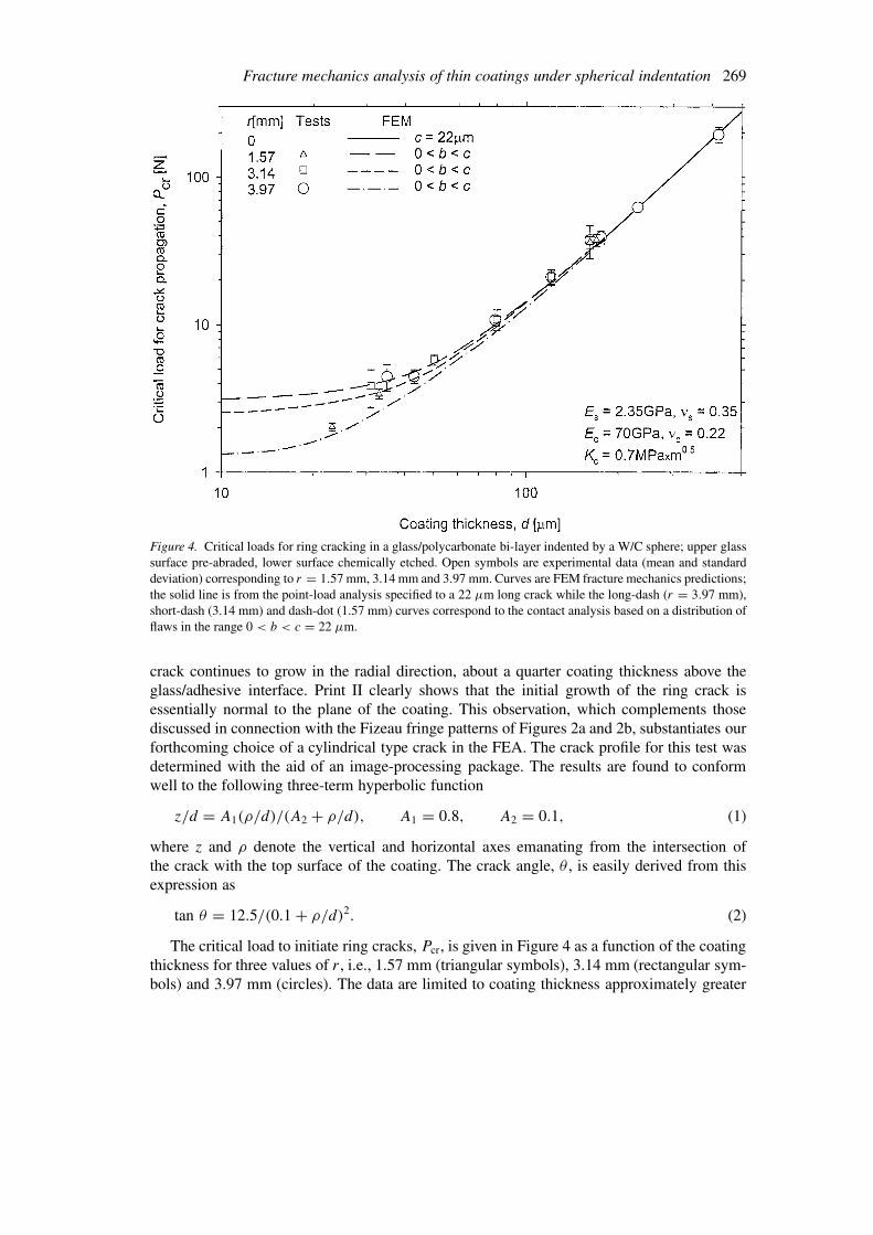
Figure 4. Critical loads for ring cracking in a glass/polycarbonate bi-layer indented by a W/C sphere; upper glasssurface pre-abraded, lower surface chemically etched. Open symbols are experimental data (mean and standarddeviation) corresponding to r = 1.57 mm, 3.14 mm and 3.97 mm. Curves are FEM fracture mechanics predictions;the solid line is from the point-load analysis specified to a 22 µm long crack while the long-dash (r = 3.97 mm),short-dash (3.14 mm) and dash-dot (1.57 mm) curves correspond to the contact analysis based on a distribution offlaws in the range 0 < b < c = 22 µm.
crack continues to grow in the radial direction, about a quarter coating thickness above theglass/adhesive interface. Print II clearly shows that the initial growth of the ring crack isessentially normal to the plane of the coating. This observation, which complements thosediscussed in connection with the Fizeau fringe patterns of Figures 2a and 2b, substantiates ourforthcoming choice of a cylindrical type crack in the FEA. The crack profile for this test wasdetermined with the aid of an image-processing package. The results are found to conformwell to the following three-term hyperbolic function
z/d = A1(ρ/d)/(A2 + ρ/d), A1 = 0.8, A2 = 0.1, (1)
where z and ρ denote the vertical and horizontal axes emanating from the intersection ofthe crack with the top surface of the coating. The crack angle, θ , is easily derived from thisexpression as
tan θ = 12.5/(0.1 + ρ/d)2. (2)
The critical load to initiate ring cracks, Pcr, is given in Figure 4 as a function of the coatingthickness for three values of r, i.e., 1.57 mm (triangular symbols), 3.14 mm (rectangular sym-bols) and 3.97 mm (circles). The data are limited to coating thickness approximately greater

270 H. Chai
than 30 µm due to the aforementioned difficulty in detecting precisely the onset of cracks forvery thin coatings. It is apparent that the fracture load gradually departs from the familiar d2
dependence as d is decreased. The effect of the sphere radius comes into play once the coatingthickness is decreased from about 150 µm, with the fracture load in this range increasing withr. The fracture load for relatively thick coatings (say d > 150 µm) can thus be accuratelyderived from a relatively simple point-load fracture analysis. In the followings, a fracturemechanics approach is developed for predicting critical loads analytically for a concentratedload as well as finite size indenters.
3. Finite element analysis
A commercial Finite Element code (ANSYS Inc., Version 5.7) is used to evaluate the onset offracture in the coating due to spherical indentation. A cylindrical crack of length c emanatingfrom the upper coating surface is considered. Axisymmetric and large-strain conditions areinvoked in the FEA. The motivation for the latter choice will become clear in the followings.The substrate and the coating are assumed linearly elastic, with νs = 0.35 and νc = 0.22.The indenter is a W/C sphere. The interface is assumed well bonded as no delamination wasobserved in the tests. The load transfer between the ball and the coating is modeled using abuilt-in contact algorithm with frictionless contact. (It has been shown for ultra thin coatingsthat the friction coefficient may greatly affect the stress distribution in the coating [Wanget al., 1998]). For the thickness range of interest here, frictional effects are believed to besmall). We first consider point loading (Section 3.1) before moving on to finite size indenters(Section 3.2). In both the cases, the analysis starts with an uncracked coating, from whichuseful empirical relations between the radial stresses responsible for crack propagation andthe system parameters are delineated. A fine mesh in all regions of stress concentration is used.Convergence of the solution is insured by systematically refining the FEM grid. The thickness,H , and the lateral extent of the substrate, L, (see Figure 1) are taken to be sufficiently large soas represent a half-space type support. It is found that this requirement becomes more stringentas the load is increased. The choice H = L/2 = 150d was found to insure the desired supportover the entire range of parameters used in this work.
3.1. FRACTURE ANALYSIS: POINT-LOAD
The concentrated stress regions on the lower and upper coating surfaces corresponding tothe uncracked coating are studied first (Section 3.1.1). Next, a fracture mechanics analysis isperformed for a cracked coating (Section 3.1.2). For both the analyses, a small sphere radius(0.05 mm) and a small load (P = 0.1 N) are used in order to minimize the contact radius inrelation to the coating thickness. The coating thickness and the elastic moduli of the coatingand the substrate are systematically varied.
3.1.1. Uncracked coatingFigure 5 shows contours of radial (i.e., normal to the loading direction) stresses at increasingload levels for a glass bonded to two different substrates, i.e., Es/Ec = 0.034 (a) and 0.3(b). In both the cases, d = 25 µm and r = 3.97 mm. The presentation is limited to thepositive stresses within half the coating region. Consider at this stage the first print (i.e., printI) in (a) and (b), where, by virtue of the smallness of the load, the results are representativeof point loading even though the indenter size is finite. Two regions of stress concentration

Fracture mechanics analysis of thin coatings under spherical indentation 271
Figure 5. FEM radial stress contours at increasing loads for two bi-layer systems indented by a W/C sphere; onlypositive stresses within half the coating region are shown. (a) Es/Ec = 0.034, (b) Es/Ec = 0.3. The contactradius, a, is indicated by vertical arrows.
are apparent, one at the lower coating surface, right under the ball, and the other at the topsurface, a distance from the loading axis. These stresses may cause transverse cracking inthe coating. Figure 6a (filled symbols) shows the dependence of the peak radial stress, σ , onthe coating thickness for a glass/polycarbonate bi-layer system, where the subscripts ‘l’ and‘u’ are used to distinguish between the lower and upper coating surfaces, respectively. Theresults clearly show that both σl and σu are inversely proportional to d2 throughout the layerthickness range. (This is in line with the 1/ρ2 type stress decay characterizing the monolithconfiguration, where ρ is the radial distance from the loading axis [e.g., Johnson, 1996]). The

272 H. Chai
Figure 6. FEM point-load predictions for the variations of σl and σu, the peak radial stresses on the lower andupper coating surface, respectively, and of Ru the distance of σu to the symmetry axis, with the coating thickness(a) or the substrate/coating modules ratio (b). The results pertain to a glass/substrate bi-layer. Symbols are datapoints, curves are corresponding empirical fits from Equation (4).
ratio σl/σu seem to be fixed, being equal to 14.5. This indicates a strong preference for radialas compared to ring type cracking. Figure 6a (open circles) also shows the variation with d ofRu, the distance to the symmetry axis where the radial stress on the upper coating surface ismaximized. This quantity is seen to be proportional to d. The results of Figure 6a can thus besummarized as follows
σld2/P = fl, σud
2/P = fu, Ru/d = fR, (3)
where the dimensionless functions f depend on the elastic coefficients. Figure 6b shows FEMpredictions (symbols) pertaining to a given value of d for the variations of all three functionsf with Es/Ec. Note that the data for σu and Ru are limited to Es/Ec < 0.3 because for largerratios, the peak radial stress on the upper coating surface occurs within the singular fieldaround the loading point. (This may not be the case, however, for the more practical case of afinite radius indenter.) Figure 6b shows that all three functions under consideration monotoni-cally decrease with increasing the substrate stiffness. Following Lawn and co-workers in theiranalysis of radial cracks, we attempt the following logarithmic type fit to all three functionsf :
f = B log[C(Ec/Es)(1 − ν2s )/(1 − ν2
c )], (4)
where B and C are constants. The solid line curves in Figure 6 are predictions based on thisrelation, with (B,C) = (0.7, 1.3), (0.022, 65) and (2.3, 1.7) for fl, fu and fR, in that order.As shown, these predictions fit reasonably well all three sets of data.

Fracture mechanics analysis of thin coatings under spherical indentation 273
Table 1. Coefficients for stress intensity factors and crack distance - point load analysisa.
Ki or R/d Es/Ec a0 a1 a2 a3 a4 a5
K1 0.034 0.0781 −0.0686 −0.0403 0.2214 −0.4806 0.2946
K2 0.034 1.0744e-3 9.6653e-3 −0.0434 0.2678 −0.5210 0.2893
R/d 0.034 3.5948 4.5138 −44.5550 170.6097 −266.482 149.8315
K1 0.15 0.0600 −0.0816 −0.0184 0.0489 −0.0401 0.0364
K2 0.15 −8.5941e-3 0.1756 −0.8340 1.8485 −1.9802 0.8102
R/d 0.15 2.3001 −1.6603 12.9127 −11.1762 −24.9412 37.0313
K1 0.6 0.0624 −0.2689 0.5545 −0.6608 0.4269 −0.1128
K2 0.6 0.0109 −0.0406 0.0507 −0.0212 0 0
R/d 0.6 −2.3393 42.7907 −171.4575 331.0676 −288.532 95.3003
aKid2/[P(πc)0.5] or R/d = a0 + a1(c/d)1 + a2(c/d)2 + a3(c/d)3 + a4(c/d)4 + a5(c/d)5.
3.1.2. Cracked coatingReferring to Figure 1, consider a cylindrical crack of length c extending from the upper coatingsurface, a distance R from the symmetry axis. The stress intensity factors and the critical loadfor the propagation of this crack are evaluated next.
3.1.2.1. Stress intensity factors.
Let the mode I and mode II stress intensity factors, K1 and K2, be written as
Ki = αi(P/d2)√
πc, i = 1, 2, (5)
where αi, i = 1, 2, are some functions of c/d. Note that the term P/d2 in Equation (5),which has a unit of stress, is motivated from Equation (3). The load needed to cause crackpropagation, Pcr, is obtained when the energy release rate, G, reaches its critical value, Gc,where
G = (K21 + K2
2 )(1 − ν2c )/Ec. (6)
For simplicity, we shall assume that Gc is independent of the mode mix, being equal to themode I fracture energy, Gic; such assumption characterize reasonably well the fracture ofbrittle solids (Erdogan and Sih, 1963). Making use of Equations (5) and (6), one has
Pcr = Kcd2/
√πc(α2
1 + α22), (7)
where
Kc ≡√
EcGc/(1 − ν2c ). (8)
The functions αi are evaluated from the FEA as follows. Let u1 and u2 denote the openingand shearing displacements on the crack flank, a distance � from the crack tip, respectively.LEFM then gives (e.g., Ewalds and Wanhill, 1986)
ui = 4(1 − ν2c )Ki
√�/2π
Ec
, i = 1, 2. (9)
274 H. Chai
Using Equations (5) and (9), one has
αi = (Ecd2/P )(ui/
√8�c)
(1 − ν2c )
, i = 1, 2. (10)
FEA are performed for various values of d, all with c = 0.03 mm and P = 0.1 N. A fine,uniform mesh made of square grids having a cell size of 0.25 µm is implemented at the cracktip vicinity. The existence of a K-field solution is assessed by comparing the distribution ofthe displacements behind the crack tip with the theoretical 1/s0.5 type decay, where s denotethe distance from the crack tip. This relationship is generally maintained to within severalpercents. By inserting in Equation (10) the values of ui at s = � from the FEA, αi could bedetermined for a given value of d. To implement this procedure, the crack distance R shouldbe determined. Because R is not known in advance, results are obtained for various values ofR, with the final choice made based on the requirement of maximum energy release rate or,from Equation (7), the largest value of α2
1 + α22 . This procedure is then repeated for various
values of d. The results for three choices of Es/Ec (i.e., 0.034, 0.15 and 0.6) are given inFigure 7a, where the filled and the open symbols denote mode I and mode II components,respectively, while the corresponding solid and dashed line curves are 5-term polynomial fitswhich coefficients are given in Table 1. Note that the results for Es/Ec = 0.6 are limited toc/d > 0.15 because for smaller values, the maximum energy release rate tends to occur withinthe singular field around the loading point. It is seen that in each case, K2 is generally muchsmaller than its mode I counterpart. The latter monotonically decreases with increasing c/d,tending to zero when the crack length approaches the coating/substrate interface. Increasingthe substrate stiffness reduces K1. Figure 7b shows the crack distance associated with Fig-ure 7a, with symbols and curves again denoting FEM data and their 5-term polynomial fits,the latter of which are given in Table 1. The results show that R increases with the ratio c/d.For c/d � 1, the data coincide with Ru, the distance of the peak radial stress correspondingto the uncracked coating (Figure 6b).
3.1.2.2. Critical load.
The normalized critical load from Equation (7) is plotted as solid lines in Figure 8 in twoalternative forms. Results are given for three choices of Es/Ec, i.e., 0.034, 0.15 and 0.6. Thepresentation in Figure 8a is convenient for following the dependence of Pcr on d for a fixedcrack length. Consider first the case of a soft substrate, i.e. Es/Ec = 0.034. For relativelythick coatings, the critical load increases proportionately to d2. As the ratio d/c decreases anoticeable departure from this trend occurs, with the fracture resistance dramatically increaseswhen the coating thickness approaches the length of the crack. This strengthening effect,which results from the bending-induced compression stress field ahead of the crack tip, isa unique feature of indentation type loading. The presentation in Figure 8b is convenientfor following the crack history for a fixed coating thickness. For this purpose, we shall as-sume that the growth of the crack is self-similar, even though the tests show that this is notthe case. Consider the case where c/d is initially set to 0.1. As the load is increased fromzero, one moves along the dotted vertical line until point A is reached, at which time crackpropagation occurs. The ensuing growth is unstable, terminating at Point B (dynamic effectsnotwithstanding). Upon increasing the load from that point, the growth become stable, butthe crack never reaches the lower surface of the coating. One also observes that for a coatingthickness less than the minimum in the curve, i.e., point C (c/d = 0.34), the growth is stable.

Fracture mechanics analysis of thin coatings under spherical indentation 275
Figure 7. FEM fracture mechanics predictions of ring cracking for three different bi-layer systems indented bya concentrated force; (a) variations of the normalized stress intensity factors with the normalized crack length,(b) the associated distance from the symmetry axis where the crack is placed. Note that the latter is dictated by amaximum energy release rate requirement. Symbols are data points, curves are corresponding 5-term polynomialfits which coefficients are given in Table 1.

276 H. Chai
Figure 8. FEM fracture mechanics predictions for the load needed to initiate a ring crack in a bi-layer indentedby a concentrated force; (a) normalized load vs. normalized coating thickness, (b) normalized load vs. normalizedcrack length. Results are given for three different substrate/coating modulus ratios. The solid lines in (a) and (b)and the dotted lines in (a) correspond to a single crack of length c (Equation (7)) and a population of flaws in therange 0 < b < c (Equation (11a)), respectively.
As will be shown next, this minimum has a special significance when the coating surfacecontains a population of flaws of various sizes instead of a single crack. The behavior for theother material combinations in Figure 8 is generally similar to that described. One notes thatdecreasing the modulus mismatch lead to an increase in the fracture resistance.
3.1.2.3. Consideration of flaw population.
Next consider the case where the coating surface contains a distribution of cracks or flawsof various sizes. This may occur naturally in polycrystalline materials (i.e., in the microstruc-tural details) or during service in an amorphous coating. While in most fracture scenariosthe failure generally originate from the largest crack in the population, here, because of theshielding effect provided by the compression stress field ahead of the crack tip, under certainconditions failure may actually initiate from small rather than large flaws in the population.This is illustrated visually in Figure 11a, to be discussed later, where the variation of Pcr withd from Equation (7) is specified to several crack lengths. As shown, while the largest crack isthe detrimental one for thick coatings, smaller and smaller cracks dominate the fracture as thecoating thickness is decreased. Let a population of cracks ranging in size from 0 to c exists onthe coating surface. As discussed in connection with Figure 8b, for a given value of d thereexists a certain crack within this population (i.e., Point C in that figure) that provide the leastfracture resistance. Denote this crack length as b, and let β = b/d, where β is a parameterdepending on the modulus ratio Es/Ec, being equal to 0.34 in the case Es/Ec = 0.034.Substituting b = βd for c in Equation (7), Equation (11a) below is obtained. The entiresolutions is thus given as
Pcr = Kcd1.5/
√πβ[α2
1(β) + α22(β)], d/c < 1/β, (11a)
Fracture mechanics analysis of thin coatings under spherical indentation 277
Pcr = Kcd2/
√πc(α2
1 + α22), d/c > 1/β. (11b)
Note that the critical load in Equation (11a) is proportional to d1.5. Equation (11a) is plottedin Figure 8a as straight, dotted lines for our three choices of Es/Ec. These lines are terminatedwhere they meet the solid lines (i.e., Equation (11b)), because for larger d/c values, theassociated flaw size exceed the largest flaw in the population, c. Figure 8a shows that thisconsideration drastically lower the fracture load for very thin coatings.
3.2. FINITE SIZE INDENTER
The effect of the indenter radius is studied next. The extended contact region that is developedunder the indenter induces geometrically nonlinear effects. The FEA in this case is similar tothe point-load analysis except that the large-strain option in Ansys is invoked. The need forthis will be discussed in the followings. We again consider the uncracked coating case beforemoving on to fracture mechanics considerations.
3.2.1. Uncracked coatingReturning to Figure 5, as the load is increased, the radial stress on the lower coating surfaceis seen to diffuse, with its peak shifting away from the symmetry axis. In addition, the tensilestress occupies a lesser portion of the coating thickness, with the magnitude of the peak stressactually decreasing with load. The peak stress on the upper coating surface occurs ahead of theedge of the contact circle (identified by the vertical arrows), but this departure decreases withload. Comparison of Figures 5a and 5b shows that these effects accentuate with increasingthe stiffness of the substrate. Figure 9 details such observations quantitatively for two choicesof modulus ratio, i.e., 0.034 and 0.2, both corresponding to d = 15 µm, r = 1.57 mm andEc = 70 GPa. The filled symbols and the solid line curves in this figure are individual datapoints and their smooth line fits, respectively, from the large-strain FEA. Figures 9a and 9bshow the variations of the peak radial strains on the lower and upper coating surfaces, εl andεu, respectively, with the normalized downward displacement of the indenter, h/d (a), or thenormalized contact radius, a/d, for the case Es/Ec = 0.034. In both of these presentations,the radial strain on the lower coating surface first increases before leveling off. The latter eventtakes place when h/d increases from about 0.1 or when a/d increases from about 2. On theother hand, the peak radial strain on the upper coating surface monotonically increases witheither h/d or a/d. In fact, when the load becomes sufficiently large, the peak radial strain onthe upper coating surface exceeds its lower surface counterpart. Figures 9c and 9d show thatincreasing the substrate stiffness reduces εl while increases εu, i.e., favoring ring type crackingat the expense of radial cracking. Also shown in Figures 9a–d (open symbols and associateddashed curves) are corresponding results produced by invoking the small-strain option in theFEA. As shown, this simplification underestimates the peak strains once h/d increases fromabout 0.1 or a/d increases from about 2. Figure 9e details the variation with the normalizedcontact radius of the location of the peak radial strain on the lower and upper coating surfaces,Rl and Ru, respectively. The peak strain on the lower coating surface is seen to depart fromthe symmetry axis once a/d increases from about 3. Thereafter, Rl monotonically increases,lagging behind the edge of the contact circle by a fixed amount, i.e., about twice the coatingthickness. The peak strain on the upper coating surface is initially remote from the contactedge, but the difference diminishes as the load is increased, tending again to a fixed value thatdepends on the modulus ratio once a/d is increased from about 3. Finally, Figure 9f showsthe variation of the contact radius and downward displacement with the load P .

278 H. Chai
Figure 9. Uncracked coating FEM predictions for two glass/substrate bi-layers (Es/Ec = 0.034 and 0.2) indentedby a 1.57 mm radius W/C sphere. Symbols and curves are individual data points and corresponding smooth linefits, respectively; filled symbols and solid line curves correspond to the large-strain analysis, open symbols anddashed line curves are from the small-strain analysis. (a)–(d) The variations of the peak radial strains on the lowerand upper coating surfaces with the indentation displacement, h, or the contact radius, a. (e) The variation of thedistance to the symmetry axis of the peak radial strain on the lower (Rl) or upper (Ru) coating surface with thecontact radius. (f) The variations of h and a with the applied load, P .

Fracture mechanics analysis of thin coatings under spherical indentation 279
Figure 10. Uncracked coating FEM predictions for the variations of εi, the strain value for which εl and εu (thepeak radial strains on the lower and upper coating surfaces, respectively) coincide, with the normalized coatingthickness. Results are given for three different bi-layers (i.e., Es/Ec = 0.0118, 0.034, 0.3), each indented by twodifferent W/C spheres (i.e., r = 1.57 mm and 3.97 mm). Symbols and curves are data points and empirical fits(Equation (12), with εi given in units of percents), respectively.
The failure stress (or strain) concept may be used to determine the fracture loads in ultrathin coating structures provided that the crack length (or the micro structural details of thecoating material) is small compared to the coating thickness. For example, Michler et al.(1999) showed that the failure stress for a thin DLC film evaporated on a steel substrate mayapproach the theoretical limit, i.e., E/10, a fact attributed to the layer being homogeneous andapparently without defects in the very small probed volume. As shown in Figure 9, when theload becomes sufficiently large, the peak radial strain on the upper coating surface exceedsits lower surface counterpart. Let εi denote the strain level for which these two quantitiesintersect. Figure 10 (symbols) shows the variation of εi with the normalized coating thickness,d/r, for three different modulus ratios and two sphere radii, i.e., 1.57 mm and 3.97 mm. Thesedata are obtained from observations of FEM radial strain contours at increasing load levels. Itis seen that the data are amenable to normalization with respect to d/r. We have also foundthat the effect of elastic mismatch can be generalized according to the following relationship:

280 H. Chai
d/r = C1εi/ log[C2(Ec/Es)(1 − ν2s )/(1 − ν2
c )], (12)
where C1 and C2 are constants, given as 5.5 and 14, respectively. The prediction of Equa-tion (12) using these coefficients is shown in Figure 10 as solid lines. With the possibleexclusion of very large strains, these empirical relations seem to provide a reasonable fit tothe data. These curves thus separate the regions where radial and ring type cracks may beexpected; if d/r is larger than the right hand side of Equation (12), radial cracking occurswhile ring cracking takes place if d/r is less than that quantity.
3.2.2. Cracked coatingThe following FEA is limited to the experimental conditions, namely a glass/polycarbonatebi-layer subject to indentation by a W/C sphere of various radii (i.e., 1.57 mm, 3. mm and3.97 mm). The critical load for crack propagation is obtained from Equations (7) and (10),with Kc for our soda lime glass taken as 0.7 Mpa m1/2 (Lawn, 1995). As before, for a givencrack length, analyses are performed for a number of crack locations, R, with the final choicedictated by the maximum energy release rate or the least fracture load requirement. (Otherapproaches that have been employed to overcome such difficulty include the use of an arrayof cracks [Souza et al., 2001] or cohesive elements that are embedded in the constitutive model[Abdul-Baqi and Van der Giessen, 2002].)
The presence of a range of flaw sizes rather than a single crack on the abraded coatingsurface needs a special consideration. Miranda et al. (2001b) have studied the flaw distributionon the surface of a glass subject to the same abrasion procedure as used in this work. Theresulting flaws ranged in size from 0 to about 30 µm. The depth of these cracks, which isthe more relevant quantity here, is expected to be somewhat smaller. Thus, judging from thecorresponding point-load analysis discussed in connection with the dotted curves in Figure 8a,to assess the least load needed to initiate crack propagation, the entire range of crack lengthsin the flaw population must be considered. The largest flaw in the population, c, is obtainedby fitting the experimental data of Figure 4 that pertain to relatively thick coatings with theFEM point-load results pertaining to c/d → 0 (Equation (7), with the coefficients of α1(o) andα2(o) taken from Table 1); this is because in this thickness range the stress intensity factorsare insensitive to the contact details, and furthermore the largest crack dominates the failure(recall earlier discussion of Figure 11a). As shown by the solid line curve in Figure 4, a 22 µmlong crack seem to provide a good fit to the experimental data once d is increased from about150 µm. To obtain critical loads for thinner coatings, the full-fledged contact analysis is used.Figures 11b–d show the results for the three sphere radii under consideration, where in eachcase the critical load is given for a number of crack lengths. In these figures, symbols andcurves correspond to the FEM data point and their associated smooth line fits, respectively. Forcomparison purposes, analogous results from the point-load analysis are also shown in part (a)of this figure. Consider first the case r = 1.57 mm (Figure 11b). The fracture curve for a givencrack length is generally similar to its point-load counterpart, except that it progressively liftsand flattens out as c is decreased. An interesting observation from Figure 11b is that when c isdecreased from about 4 µm, the fracture curve experiences a fundamental transition, i.e., froma concave form to one that is monotonically decreases with decreasing the coating thickness.Observations of radial stress profiles in the uncracked coating case in this thickness range showthat the above departure is a consequence of the transition from bending toward membranetype deformations. The later phenomenon, which was the basis for the fracture analysis byBegley et al. (1999) in their study of ultra thin DLC films on elastic-plastic substrates, will

Fracture mechanics analysis of thin coatings under spherical indentation 281
Figure 11. FEM fracture mechanics predictions for the variations with the coating thickness of the load needed toinitiate a ring crack in a glass/polycarbonate bi-layer due to indentation by W/C spheres of various radii: (a) r → 0,(b) r = 1.57 mm, (c) r = 3.14 mm, (d) r = 3.97 mm. In each case, results are given for several crack lengths. Thecurves in (a) are from Equation (7), the symbols and curves in (b)–(d) are individual FEM data points and theirsmooth line fits, respectively.
not be addressed further in this work. Figures 11c and 11d show that the trends noted forFigure 11b tend to accentuate as r is increased, with the transition toward ‘membrane’ typefracture taking place at increasing valued of d.
Clearly, when the coating surface contains a continuous population of flaws, the least frac-ture load obtained among all possible choices of crack lengths less than c would constitute thecritical load. The variation of the critical load so defined with the coating thickness can thusbe ascertained from Figure 11 by drawing a smooth curve through the lowest point data per-taining to a given value of r. The resulting fracture envelopes are depicted in Figure 12a. Notethat the point-load result (i.e., the solid line curve) is constructed directly from Equation (11a).Note also that the rest of the fracture envelopes are limited to the coating thickness range forwhich the ‘bending’ mode of fracture dominates; for the ‘membrane’ mode of deformation,

282 H. Chai
Figure 12. FEM results associated with Figure 11. (a) Fracture envelopes for r → 0, 1.57 mm, 3.14 mm and3.97 mm; each of these curves is generated by drawing a smooth line through the corresponding lowest fracturedata in Figure 11. Also shown in this figure are the variations with r/d of R/d (b) and R/a (c) associated with thefracture envelopes pertaining to r > 0 in (a); symbols or curves are FEM data points and their smooth line fits,respectively.

Fracture mechanics analysis of thin coatings under spherical indentation 283
the fracture load would be dictated by the largest flaw in the population. The critical loads fromFigure 12a seem independent of the indenter radius for coating thickness exceeding about150 µm. For thinner coatings, the fracture curves depart, each tending to a steady-state valuewhich magnitude increases with the bluntness of the indenter. Figures 12b and 12c (symbols)show the variations of the crack distance associated with the fracture envelopes of Figure 12awith r/d. The data are normalized either with respect to the coating thickness (b) or the contactradius (c). It is apparent from these figures that the results are amenable to normalization withr/d,R/d and R/a. As evident by the solid line in Figure 12b, for r/d > 20 the data seem wellfitted according to R/d = C3(1+C4r/d), where C3 = 2.1 and C4 = 0.018. Figure 12c showsthat when r/d exceeds about 200, R/a ≈ 1.2. Finally, the fracture envelopes in Figure 12a arereproduced in Figure 4. The agreement between the tests and the analysis seems satisfactory.
4. Discussions
The relationship between the fracture resistance of the ring and the radial crack systems isan important design aspect. Unfortunately, a fracture mechanics analysis of the latter damageis difficult to perform due to the three-dimensional nature of the problem. The results forthe uncracked coating (Figure 9 and Equation (12)) show that the tendency for ring crackingincreases with increasing either the indenter bluntness or the failure strain of the coating, orwith decreasing either the coating thickness or the elastic mismatch ratio. The latter effectseems to be substantiated from recent spherical indentation tests reported by Lardner et al.(1997), Gilpin et al. (1996) and Ely et al. (1996). Additional support for the dominance ofthe ring or upper coating surface cracks in ultra thin coatings is provided by a recent fracturemechanics analysis of the analogous case of cylindrical or plane-strain indentation (Chai,2003). Such loading reduces the fracture problem for the crack on the lower coating surface toa relatively simple two-dimensional analysis. The latter shows that when the coating becomessufficiently thin, cracking from the lower coating surface is completely suppressed. In contrast,the fracture load for the upper surface crack tends to a finite value with decreasing d. Thecrossover in the fracture envelopes between the two crack systems depends on the bluntness ofthe indenter; for the 3 mm radius steel cylinder analyzed, the transition occurred at d ≈ 20 µm.
When c/d � 1, a failure stress criterion was found to hold well for amorphous as wellas ceramic coatings (Chai et al., 1999; Rhee et al., 2001; Miranda et al., 2001a; Chai andLawn, 2002). The relationship between the failure stress, σF, and Kc can be easily foundby substituting c/d = 0 in Equation (7) and replacing Pcr/d
2 with σFfu (Equation (3)).Neglecting the mode II contribution in this case, one finds
Kc = (a0/fu)σF
√πc, (14)
where a0 ≡ α1(0). Using values for a0 and fu from Table 1 and Equation (4), respectively,one finds a0/fu = 1.11, irrespective of Es/Ec. This prediction agrees well with the classicalresult for an edge-notched plate under uniform tension (i.e., 1.12, Ewalds and Wanhill, 1986).
5. Summary and conclusions
Spherical indentation of a thin, hard coating bonded to a soft substrate is studied experi-mentally and analytically, with special emphasis placed on the damage emanating from theupper coating surface. In-situ tests are carried out on a model transparent glass/polycarbonate

284 H. Chai
bi-layer. The use of a tough adhesive for bonding the glass to the substrate helps suppressunwanted delamination damage while the pre-etching of the lower coating surface eliminatesunwanted radial type cracks. Pre-abrasion of the top glass surface with fine particles is em-ployed as a mean to introduce flaws and reduce scatter in the fracture load. The critical load toinitiate ring cracks, Pcr, is determined over coating thickness ranging from 30 µm to 300 µmfor three different spheres radii, i.e., 1.57 mm, 3.14 mm and 3.97 mm. For relatively thickcoatings, Pcr is independent of the indenter radius, the nominal value of which increases inproportion to the square of the coating thickness. When the latter is decreased from about150 µm, the fracture loads diverge, with blunter indenters giving rise to larger fracture loads.
A large-strain, axisymmetric FEM analysis is used to study the onset of transverse fracturein the coating. The load transfer between the indenter and the coating surface is modeled usinga built-in frictionless contact algorithm. The contact loading produces concentrated tensilestresses on the lower and upper coating surfaces, from which cracks may ensue. Analyses areperformed for both uncracked and cracked coatings. In the latter case, the analysis is limitedto cylindrical cracks emanating from the upper coating surface.
The location of the expected ring crack is determined using a trial and error scheme sub-ject to the requirement of greatest energy release rate. The fracture resistance is dictated bya complex interplay between the contact area, the coating thickness and the crack length.The presence of a bending-induced compression stress field ahead of the crack tip tendsto suppress crack propagation in thin-film coatings. Consequently, when the surface of thespecimen contains a distribution of flaws or micro- structural details of various sizes, smallerentities in this population may become more detrimental than large ones. Incorporation of thisaspect into the analysis led to a good correlation with the experimental results throughout therange of parameters studied. In the special case of point loading, the analysis becomes linearlyelastic, which leads to a closed-form, approximate solution for the stress intensity factors orthe critical loads. In addition to being directly applicable to relatively thick coatings (i.e.,a/d � 1), this solution also provides lower bounds for the critical loads in the thin coatingregime. When a flaw distribution is considered, the critical load in this range is proportionalto d1.5.
When the cracks present on the coating surfaces are small compared to the coating thick-ness, the stress analysis of the uncracked coating may be used to predict fracture. The resultsshow that in applications that promote relatively large contact area (i.e., thin and/or toughcoatings, blunt indenters, stiff substrates), ring cracking on the upper coating surface may pre-cede radial cracking on the lower coating surface. In fact, when a/d is sufficiently large, radialtype cracking is completely suppressed. A simple analytic expression is given for predictingthe transition between these two failure modes as a function of the geometric and materialparameters of the system.
References
Abdul-Baqi, A. and Van der Giessen, E. (2002). Numerical analysis of indentation-induced cracking of brittlecoatings on ductile substrates. International Journal of Solids and Structures 39, 1427–1442.
Anderson, R., Toth, G., Gan, L. and Swain, M.V. (1998). Indentation response and cracking of sub-micron silicafilms on a polymeric substrate. Engineering Fracture Mechanics 61, 93–105.
Begley, M.R., Evans, A.G. and Hutchinson, J.W. (1999). Spherical impression of thin elastic films on elastic-plasticsubstrates. International Journal of Solids and Structures 36, 2773–2788.
Chai, H., Lawn, B.R. and Wuttiphan, S. (1999). Fracture modes in brittle coatings with large interlayer modulusmismatch. Journal of Material Research 14, 3805–3817.

Fracture mechanics analysis of thin coatings under spherical indentation 285
Chai, H. and Lawn, B.R. (2002). Cracking in brittle laminates from concentrated loads. Acta Materialia 50, 2613–2625.
Chai, H. (2003). Fracture mechanics analysis of thin coatings under plane-strain indentation. International Journalof Solids and Structures 40, 591–610.
Diao, D.F., Kato, K. and Hokkirigawa, K. (1994). Fracture mechanism of ceramic coatings in indentation. Journalof Tribology 116, 860–869.
Ely, J.L., Stupka, J. and Haubold, A.D. (1996). Pyrolytic carbon indentation crack morphology. The Journal ofHeart Valve Disease 5, S65–S71.
Erdogan, F. and Sih, G.C. (1963). On the crack extension in plates under plane loading and transverse shear.Journal of Basic Engineering 85, 519–527.
Ewalds, H.L. and Wanhill, R.J.H. (1986). Fracture Mechanics, Edward Arnold Publishers, New York.Gilpin, C.B., Haubold, A.D. and Ely, J.L. (1996). Finite element analysis of indentation tests on pyrolytic carbon.
The Journal of Heart Valve Disease Suppl. I, S72–S78.Hainsworth, S.V., McGurk, M.R. and Page, T.F. (1998). The effect of coating cracking on the indentation response
of thin hard-coated systems. Surface and Science Technology 102, 97–107.Hayashi, K. and Yuan, F. (1999). Elastic-Plastic analysis of stresses and initiation of cracks in a ceramic coating
under indentation by an elastic sphere. Journal of Tribology 120, 453–469.Johnson, K.L. (1996). Contact Mechanics. Cambridge University Press, Cambridge.Lardner, J.L., Ritter, J.E. and Gao-Qiu Zhu (1997). Spherical indentation and fracture of glass plates. Journal of
the American Ceramic Society 80, 1851–1862.Lawn, B.R. (1995). Fracture of Brittle Solids, Second Edition, Cambridge University Press, Cambridge.Li, X. and Bhushan, B. (1998). Measurement of fracture toughness of ultra-thin amorphous carbon films. Thin
Solid Films 315, 214–221.Michler, J., Tobler, M. and Blank, E. (1999). Thermal annealing behavior of alloyed DLC films on steel:
determination and modeling of mechanical properties. Diamond and Related Materials 8, 510–516.Miranda, P., Pajares, A., Guiberteau, F., Cumbrera, F.L. and Lawn, B.R. (2001a). Contact fracture of brittle bilayer
coatings on soft substrates. Journal of Materials Research 16, 115–126.Miranda, P., Pajares, A., Guiberteau, F., Cumbrera, F.L. and Lawn, B.R. (2001b). Role of flaw statistics in contact
fracture of brittle coatings. Acta Materialia 49, 3719–3726.Rhee, Y.-W., Kim, H.-W., Deng, Y. and Lawn, B.R. (2001). Contact-induced damage in ceramic coatings on
compliant substrates: fracture mechanics and design. Journal of the American Ceramic Society 84, 1066–1072.Souza, R.M., Sinatora, A., Mustoe, G.G.W. and Moore, J.J. (2001). Numerical and experimental study of the
circular cracks observed at the contact edges of the indentations of coated systems with soft substrates. Wear251, 1337–1346.
Wang, J.S., Sugimura, Y., Evans, A.G. and Tredaway, W.K. (1998). The mechanical performance of DLC films onsteel. Thin Solid Films 325, 163–174.
Weppelmann, E. and Swain, M.V. (1996). Investigation of stresses and stress intensity factors responsible forfracture of thin protective films during ultra-micro indentation tests with spherical indenters. Thin Solid Films286, 111–121.
Yuan, F. and Hayashi, K. (1999). Influence of the grain size of the alumina coating on crack initiation inindentation. Wear 225–229, 83–89.