frame-evo-e20 · 2019-09-16 · frame-evo-e20 mounting frame for projectors manual version 1.8 date...
TRANSCRIPT
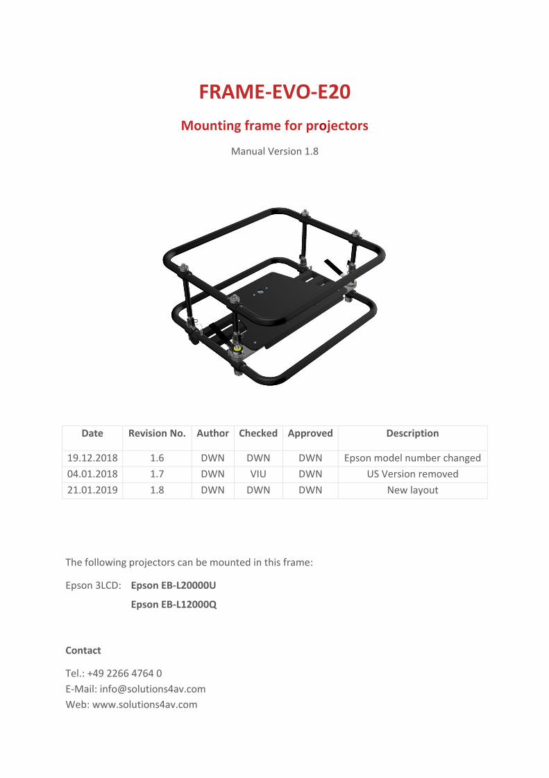
FRAME-EVO-E20
Mounting frame for projectors
Manual Version 1.8
Date Revision No. Author Checked Approved Description
19.12.2018 1.6 DWN DWN DWN Epson model number changed
04.01.2018 1.7 DWN VIU DWN US Version removed
21.01.2019 1.8 DWN DWN DWN New layout
The following projectors can be mounted in this frame:
Epson 3LCD: Epson EB-L20000U
Epson EB-L12000Q
Contact
Tel.: +49 2266 4764 0
E-Mail: [email protected]
Web: www.solutions4av.com

Manual FRAME-EVO-E20 Version 1.6
21.01.2019
Page 1 of 39

Manual FRAME-EVO-E20 Version 1.6
21.01.2019
Page 2 of 39
Table of content
1. Preamble .................................................................................................... 3
1.1 FRAME-EVO-E20 designation ........................................................................................................ 3
1.2 Tools required ............................................................................................................................... 4
2. Safety instructions ...................................................................................... 4
3. What’s in the box? .................................................................................... 10
4. Optional Accessories ................................................................................. 11
5. Fitting the projector in the frame .............................................................. 14
6. Removing the Upper Ring - Installation Version ........................................ 16
7. Reinstalling the Upper Ring ....................................................................... 19
8. Adjustment options ................................................................................... 21
9. Stacking frames ......................................................................................... 23
10. Mounting the frame on a truss ................................................................ 24
11. Maximum stacking information ............................................................... 26
12. System maintenance and inspection (Re-examination) ........................... 33
13 Declaration of Conformity ........................................................................ 36
14 Dimensions ............................................................................................... 37
14.1 FRAME-EVO-E20 ........................................................................................................................ 37
14.2 FRAME-EVO-E20 Installation Version - without the Upper Ring ............................................... 38
Imprint .......................................................................................................... 39

Manual FRAME-EVO-E20 Version 1.6
21.01.2019
Page 3 of 39
1. Preamble Congratulations on your purchase of the FRAME-EVO-E20 projector frame from LANG AG.
Please read very carefully the instructions provided in this manual. In the following pages
you will find all the information needed for a safe and fast installation.
After the installation is done properly, you can enjoy all the features of your new product.
Please consider keeping the original box and packaging materials, in case you ever need to
ship the frame.
Model number: FRAME-EVO-E20
1.1 FRAME-EVO-E20 designation
Note: In this manual, when reference is made to the manufacturer model number it is also
automatically a reference to the Epson model number like described in the table below:
Description Number
Manufacturer model number FRAME-EVO-E20
Epson model number ELPMB57
Epson SKU V12H989B57
Manual FRAME-EVO-E20 Version 1.6
21.01.2019
Page 4 of 39
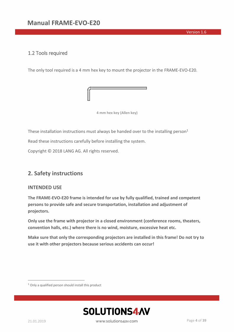
1.2 Tools required
The only tool required is a 4 mm hex key to mount the projector in the FRAME-EVO-E20.
These installation instructions must always be handed over to the installing person1
Read these instructions carefully before installing the system.
Copyright © 2018 LANG AG. All rights reserved.
2. Safety instructions
INTENDED USE
The FRAME-EVO-E20 frame is intended for use by fully qualified, trained and competent
persons to provide safe and secure transportation, installation and adjustment of
projectors.
Only use the frame with projector in a closed environment (conference rooms, theaters,
convention halls, etc.) where there is no wind, moisture, excessive heat etc.
Make sure that only the corresponding projectors are installed in this frame! Do not try to
use it with other projectors because serious accidents can occur!
1 Only a qualified person should install this product
4 mm hex key (Allen key)

Manual FRAME-EVO-E20 Version 1.6
21.01.2019
Page 5 of 39
WARNINGS
Installation work should only be carried out by a qualified technician.
• If this product is not installed correctly, serious accidents may result.
Do not use the FRAME-EVO-E20 frame outdoors.
• This product is made only for indoor usage. If the FRAME-EVO-E20 frame is mounted
outdoor, there are many influences like wind or rain that can have an effect on the
stability of the whole system. This can cause serious accidents and property damage.
Do not place the frame on top of unstable surfaces.
• If the frame is placed on top of a surface which is sloped or unstable, it may fall down
or tip over and injury or damage could result. Make sure that the surface can support
a load of 280 kg (617.29 lbs)2 plus the weight of all additional equipment as well as
other potential systems.
Do not hang the frame from unstable or inappropriate structures.
• If the frame is hung on an unstable structure, the entire system can fall down and
injuries may occur. Make sure that the construction can support a total weight of 280
kg (617.29 lbs) plus the weight of all additional equipment as well as other potential
systems.
Make sure to not exceed max. weight loads for ceiling mounting.
• For suspended installations, use only designated hanging accessories, like TH-SHORT-
150-8, TH-SHORT-350-8/10, FRAME-PF-UNI-PORADV2 Portrait Adapter Version 2 and
FRAME-PF-UNI-CLP5030, FRAME-PF-UNI-CLP30PT rigging clamps for a max. weight
load of 280 kg (617.29 lbs). Please refer to the corresponding instructions for the
accessories used. Please also refer to chapter “4. Optional Accessories” and “11.
Maximum stacking information”.
2 280 kg (617.29 lbs) = 3 x (weight of heaviest projector + weight of heaviest lens + weight of FRAME-EVO-E20)

Manual FRAME-EVO-E20 Version 1.6
21.01.2019
Page 6 of 39
For stacking, make sure that all four locking pins pass completely through the female
stacking bolt.
• Make sure the four male bolts enter into the correspondent female bolts and are
locked.
Do not install the FRAME-EVO-E20 or the projector while people are present under the
mounting zone during the installation process.
• When installing the projector, make sure no one is in the area underneath the
installation zone.
Always secure the frame to the rigging truss with a safety steel cable.
• The frame should always be secured with an appropriate safety steel cable so that in
case of a malfunction it doesn’t fall more than 5 cm. Please consult the local laws or
regulations regarding the additional safety of hanging equipment.
Manual FRAME-EVO-E20 Version 1.6
21.01.2019
Page 7 of 39
CAUTION
Before installing the projector in the FRAME-EVO-E20 frame, please read the projector’s
user manual. When the projector has a lens attached, please remove it.
• The FRAME-EVO-E20 frame with the projector inside must be installed only in an
environment that is recommended by the projector manufacturer.
Minimum two persons are required to install the FRAME-EVO-E20 frame.
• With regard to the overall weight of all necessary installation devices, make sure to
handle those with at least two people.
Make sure that the structure from which you hang up to 3 FRAME-EVO-E20 frames
including projectors is capable of carrying the overall weight of approx. 280 kg (617.29 lbs)
plus the weight of all additional equipment as well as other potential systems.
• Prior to any installation, you must do a visual inspection to make sure that the
system is in a good condition. For more information please refer to chapter
“12. System maintenance and inspection (Re-examination)”.
Manual FRAME-EVO-E20 Version 1.6
21.01.2019
Page 8 of 39
RISK SITUATIONS
Risk of injury due to the possibility of falling objects during the assembly or disassembly of
the FRAME-EVO-E20 frame.
• Protection objective: avoid injury from falling parts.
• Wear appropriate safety shoes, gloves and helmet.
• Make sure the area under the installing places is clear.
Risk of hitting the head with the FRAME-EVO-E20 frame during the hanging set up process.
• Protection objective: avoid injury from hitting the head.
• Wear a helmet.
Incorrect installation may lead to certain parts of the FRAME-EVO-E20 frame or the entire
FRAME-EVO-E20 frame to fall down.
• Protection objective: prevent personal injury and property damage.
• Double check the FRAME-EVO-E20 frame and its installation.
Insufficient load capacity of the supporting structure may lead to certain parts of the
FRAME-EVO-E20 frame or the entire FRAME-EVO-E20 frame to fall down.
• Protection objective: prevent personal injury and property damage.
• Provide adequate dimensioning of the supporting structure. The supporting structure
must be able to support the combined weight of all the equipment attached to, or
hung from it.
• Ensure correct installation of the supporting structure.
Manual FRAME-EVO-E20 Version 1.6
21.01.2019
Page 9 of 39
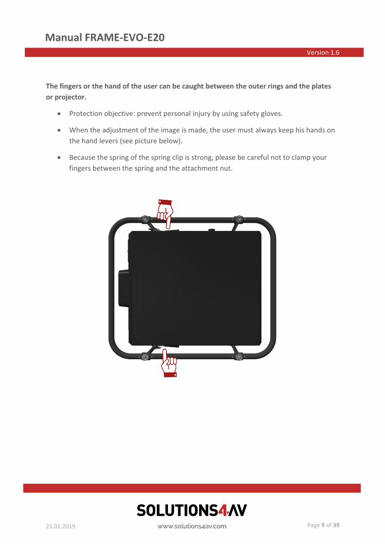
The fingers or the hand of the user can be caught between the outer rings and the plates
or projector.
• Protection objective: prevent personal injury by using safety gloves.
• When the adjustment of the image is made, the user must always keep his hands on
the hand levers (see picture below).
• Because the spring of the spring clip is strong, please be careful not to clamp your
fingers between the spring and the attachment nut.

Manual FRAME-EVO-E20 Version 1.6
21.01.2019
Page 10 of 39
3. What’s in the box?
FRAME-EVO-E20
• Used for projector installation
• Number of units: 1
• Weight: 16,2 kg / 35.715 lbs
• 6 x M6x30 ISO 7380 screws
(galvanized steel 10.9)
• 6 x Ø6 Schnorr Washer
Used to secure the projector
in the frame
User manual and installation guide
for FRAME-EVO-E20
Make sure your box contains everything you ordered. If any pieces are missing, contact the
vendor.
2
1
Manual FRAME-EVO-E20 Version 1.6
21.01.2019
Page 11 of 39
4. Optional Accessories
Please refer to chapter “10. Mounting the frame on a truss” and the following for
information regarding the usability of the optional accessories.
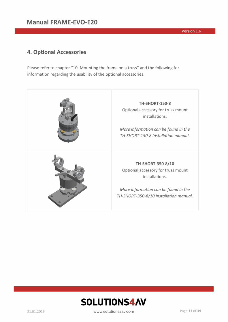
TH-SHORT-150-8
Optional accessory for truss mount
installations.
More information can be found in the
TH-SHORT-150-8 Installation manual.
TH-SHORT-350-8/10
Optional accessory for truss mount
installations.
More information can be found in the
TH-SHORT-350-8/10 Installation manual.
Manual FRAME-EVO-E20 Version 1.6
21.01.2019
Page 12 of 39
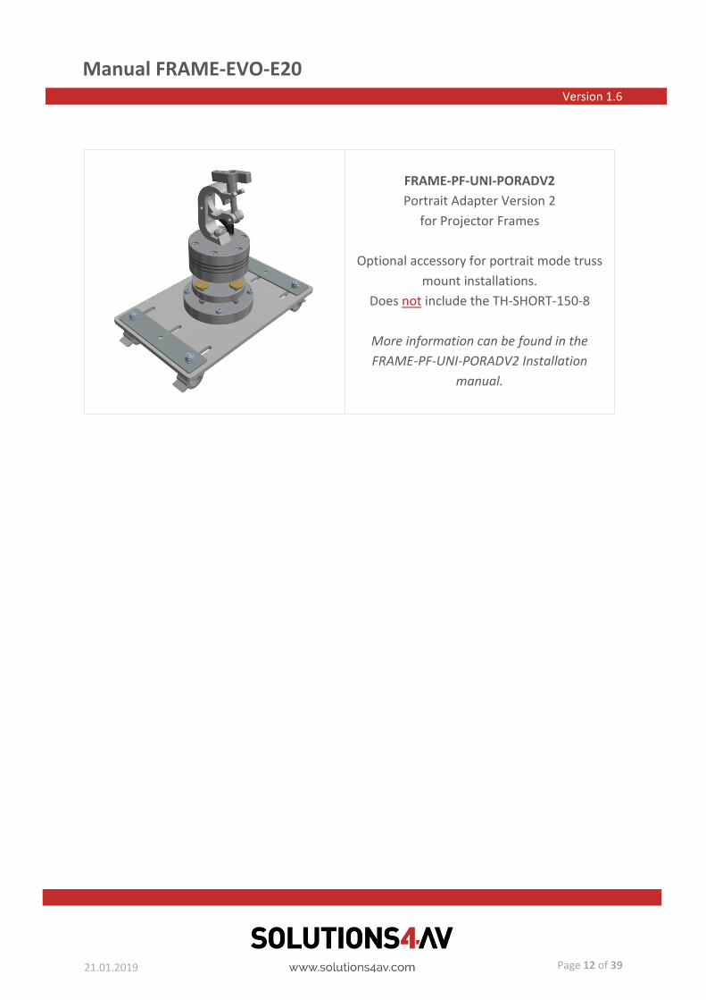
FRAME-PF-UNI-PORADV2
Portrait Adapter Version 2
for Projector Frames
Optional accessory for portrait mode truss
mount installations.
Does not include the TH-SHORT-150-8
More information can be found in the
FRAME-PF-UNI-PORADV2 Installation
manual.
Manual FRAME-EVO-E20 Version 1.6
21.01.2019
Page 13 of 39
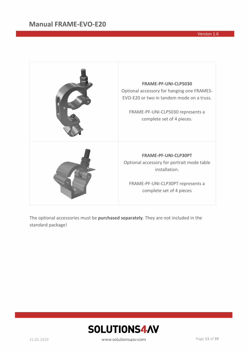
FRAME-PF-UNI-CLP5030
Optional accessory for hanging one FRAMES-
EVO-E20 or two in tandem mode on a truss.
FRAME-PF-UNI-CLP5030 represents a
complete set of 4 pieces.
FRAME-PF-UNI-CLP30PT
Optional accessory for portrait mode table
installation.
FRAME-PF-UNI-CLP30PT represents a
complete set of 4 pieces
The optional accessories must be purchased separately. They are not included in the
standard package!

Manual FRAME-EVO-E20 Version 1.6
21.01.2019
Page 14 of 39
5. Fitting the projector in the frame
Step1: Place the projector upside down on a suitable flat surface. For easier access you may
first remove the upper ring before mounting the projector. Please refer to chapter
“6. Removing the Upper Ring - Installation Version. Otherwise it is recommended to place an
appropriate material underneath the projector so that it is lifted up for about 10 cm. This
will help during the following process.
Step 2: Position the frame over the projector so that the adjustment screw is at the back,
aligning the M6 screw holes. Please put the projector in the right position so that the
front/back position is correct when installing. Otherweise the position of the holes will not
match.

Manual FRAME-EVO-E20 Version 1.6
21.01.2019
Page 15 of 39
Step 3: Place the 6 x Ø6 Schnorr Washers (2) over each corresponding hole. Secure the
6 x M6x30 ISO 7380 screws (1) into each hole with 4 Nm torque. Ensure each screw runs
through the plate and catches into the corresponding M6 hole in the projector surface.
Please make sure to use only the correspondent screw holes when installing a projector!
Do not forget to use the 6 x Ø6 Schnorr Washers (2) as they are preventing the screws to
loose themselves!
In case you removed the upper ring during Step 1 please now refer to chapter
“7. Reinstalling the Upper Ring” and attach the upper ring back to the base.
Torque: 4±0.5 Nm
1
2
Manual FRAME-EVO-E20 Version 1.6
21.01.2019
Page 16 of 39
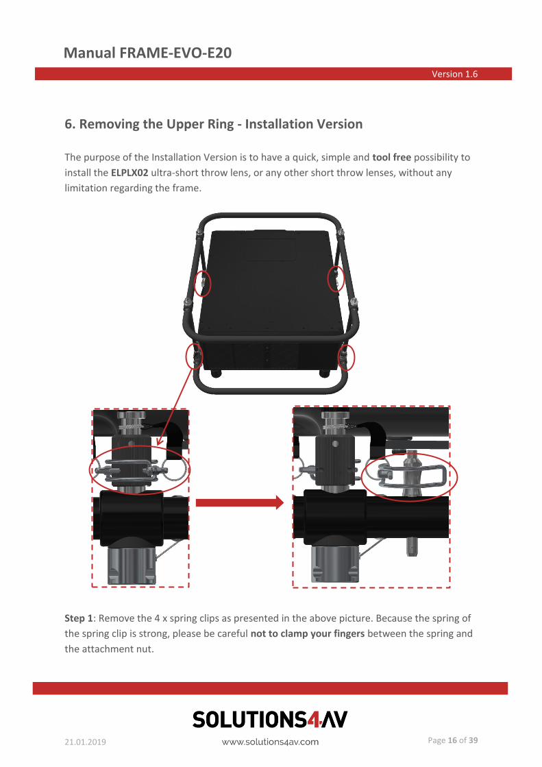
6. Removing the Upper Ring - Installation Version
The purpose of the Installation Version is to have a quick, simple and tool free possibility to
install the ELPLX02 ultra-short throw lens, or any other short throw lenses, without any
limitation regarding the frame.
Step 1: Remove the 4 x spring clips as presented in the above picture. Because the spring of
the spring clip is strong, please be careful not to clamp your fingers between the spring and
the attachment nut.
Manual FRAME-EVO-E20 Version 1.6
21.01.2019
Page 17 of 39
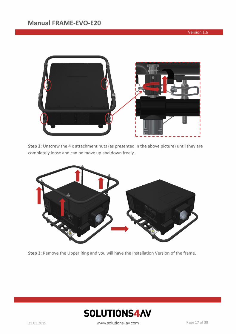
Step 2: Unscrew the 4 x attachment nuts (as presented in the above picture) until they are
completely loose and can be move up and down freely.
Step 3: Remove the Upper Ring and you will have the Installation Version of the frame.

Manual FRAME-EVO-E20 Version 1.6
21.01.2019
Page 18 of 39
Step 4: Now the ELPLX02 ultra-short throw lens can be attached to the projector.

Manual FRAME-EVO-E20 Version 1.6
21.01.2019
Page 19 of 39
7. Reinstalling the Upper Ring
Step 1: Remove the ELPLX02 ultra-short throw lens.
Step 2: Reposition the Upper Ring on the top of the Bottom Ring in such a way that the
4 x attachment nuts are on the corresponding position.

Manual FRAME-EVO-E20 Version 1.6
21.01.2019
Page 20 of 39
Step 3: Tighten back the 4 x attachment nuts until there is no play and the attachment nuts
can not be moved up or down.
Step 4: In the process of attaching the Upper Ring back to the frame, as a last step, please
don’t forget to reinsert the 4 x spring clips into the attachment nut. Because the spring of
the spring clip is strong, please be careful not to clamp your fingers between the spring and
the attachment nut.
Manual FRAME-EVO-E20 Version 1.6
21.01.2019
Page 21 of 39
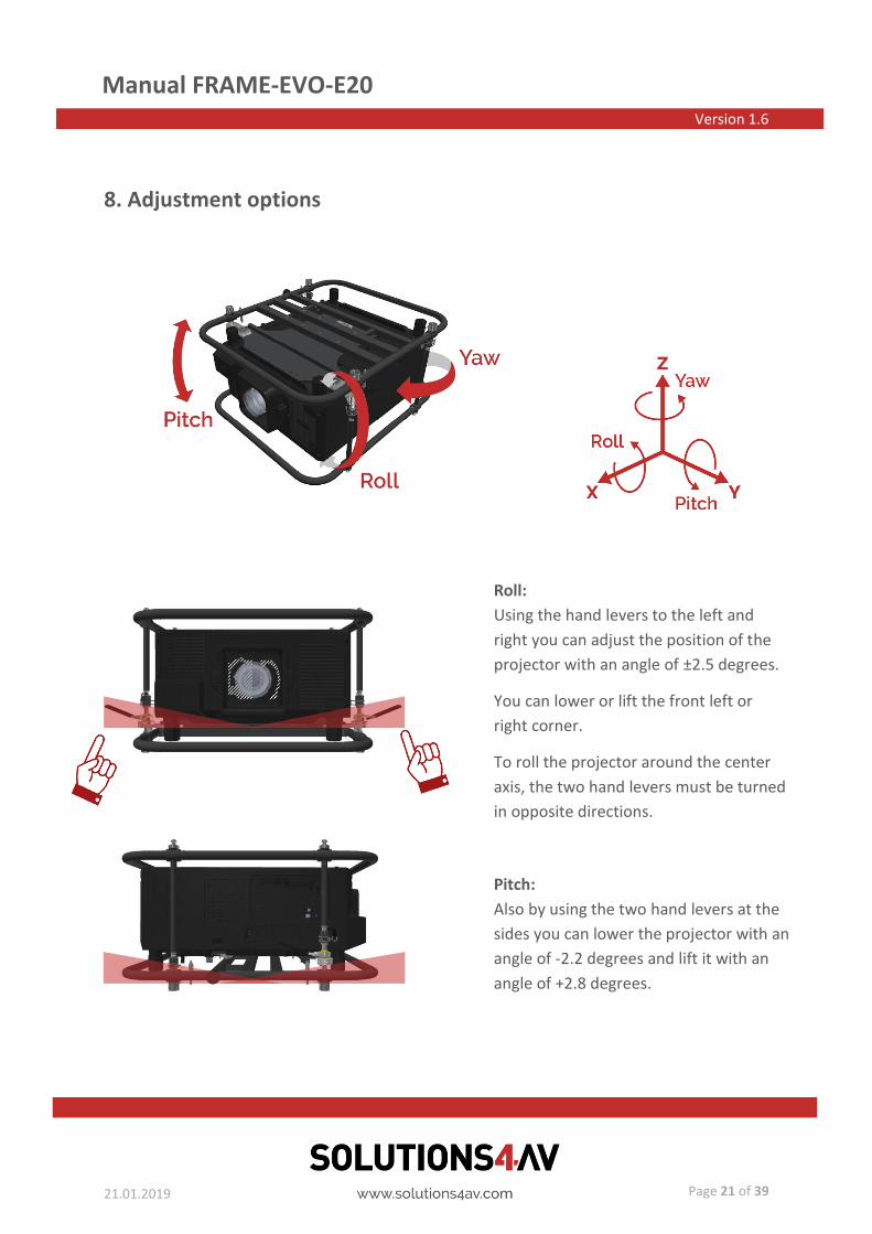
8. Adjustment options
Roll:
Using the hand levers to the left and
right you can adjust the position of the
projector with an angle of ±2.5 degrees.
You can lower or lift the front left or
right corner.
To roll the projector around the center
axis, the two hand levers must be turned
in opposite directions.
Pitch:
Also by using the two hand levers at the
sides you can lower the projector with an
angle of -2.2 degrees and lift it with an
angle of +2.8 degrees.
Manual FRAME-EVO-E20 Version 1.6
21.01.2019
Page 22 of 39
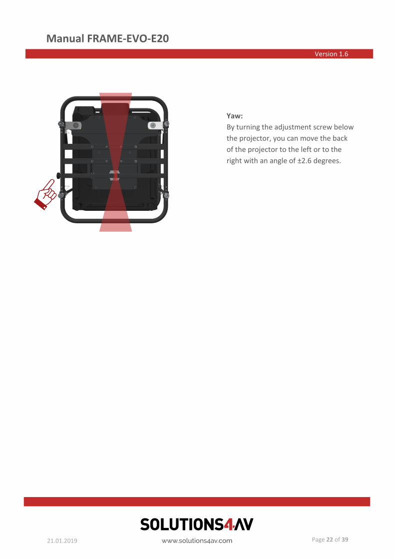
Yaw:
By turning the adjustment screw below
the projector, you can move the back
of the projector to the left or to the
right with an angle of ±2.6 degrees.

Manual FRAME-EVO-E20 Version 1.6
21.01.2019
Page 23 of 39
9. Stacking frames
Step 1: Place the upper frame with mounted projector on top of the lower frame with
mounted projector. Make sure the four male bolts enter into the correspondent female
bolts. To secure, insert the locking pins through the holes in the female bolts. Always make
sure that the locking pins are locked after being inserted.
Female bolt
Locking pin Male bolt

Manual FRAME-EVO-E20 Version 1.6
21.01.2019
Page 24 of 39
10. Mounting the frame on a truss
To hang the frame on a truss one must use the recommended 4 x M8 or/and the 4 x M10
threaded holes to attach a mounting accessory like the TH-SHORT-150-8 or TH-SHORT-350-
8/10. Use only the original and recommended accessories for this procedure.
Another mounting option is using the optional Portrait Adapter Version 2 FRAME-PF-UNI-
PORADV2 that can be mounted on the frame and then hung on the truss. For further
information regarding the setup of the Portrait Adapter Version 2 (FRAME-PF-UNI-
PORADV2), please consult the FRAME-PF-UNI-PORADV2 Installation manual.
Manual FRAME-EVO-E20 Version 1.6
21.01.2019
Page 25 of 39
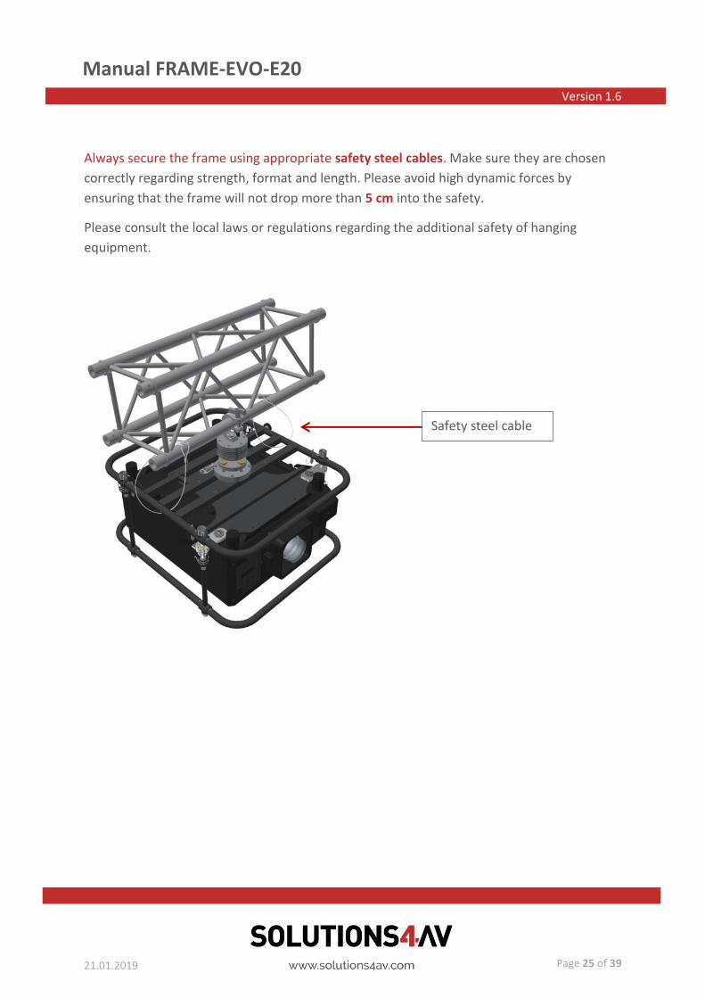
Always secure the frame using appropriate safety steel cables. Make sure they are chosen
correctly regarding strength, format and length. Please avoid high dynamic forces by
ensuring that the frame will not drop more than 5 cm into the safety.
Please consult the local laws or regulations regarding the additional safety of hanging
equipment.
Safety steel cable

Manual FRAME-EVO-E20 Version 1.6
21.01.2019
Page 26 of 39
11. Maximum stacking information
Please refer to the tables below to confirm proper usage.
Do not try to setup the frame in other positions as presented, because accidents can occur!
With TH-SHORT-150-8
Landscape
1 2
With TH-SHORT-350-8/10
Landscape
1 2

Manual FRAME-EVO-E20 Version 1.6
21.01.2019
Page 27 of 39
With rigging clamps (FRAME-PF-UNI-CLP5030)
Portrait
Landscape
1 2
Warning: triple-hanging with the rigging clamps is not possible! Please do no try to hang three
projectors with the rigging clamps beacause mechanical failure and accidents can occur.
Distance between the
rigging clamps:
• On X axis: 387 mm
• On Y axis: between
240 mm and 350 mm
Distance between the
rigging clamps:
• On X axis: 718,5 mm
• On Y axis: between
240 mm and 350 mm
Manual FRAME-EVO-E20 Version 1.6
21.01.2019
Page 28 of 39
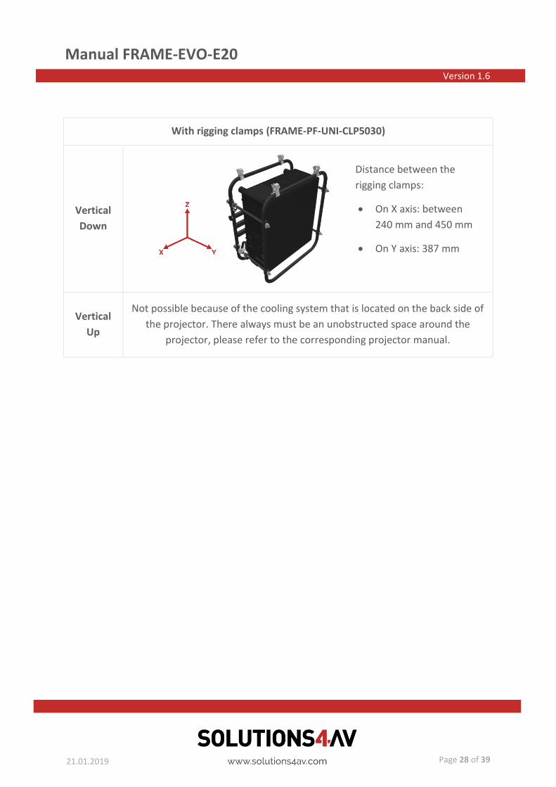
With rigging clamps (FRAME-PF-UNI-CLP5030)
Vertical
Down
Vertical
Up
Not possible because of the cooling system that is located on the back side of
the projector. There always must be an unobstructed space around the
projector, please refer to the corresponding projector manual.
Distance between the
rigging clamps:
• On X axis: between
240 mm and 450 mm
• On Y axis: 387 mm
Manual FRAME-EVO-E20 Version 1.6
21.01.2019
Page 29 of 39
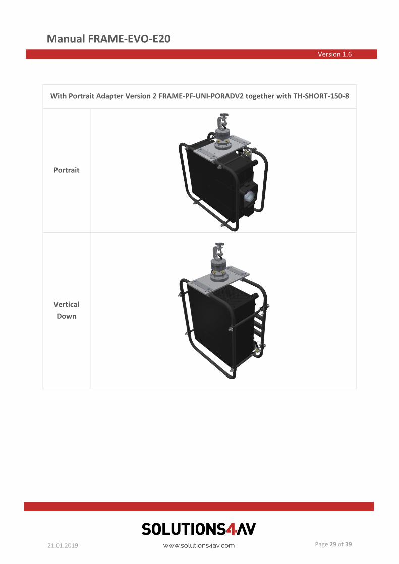
With Portrait Adapter Version 2 FRAME-PF-UNI-PORADV2 together with TH-SHORT-150-8
Portrait
Vertical
Down

Manual FRAME-EVO-E20 Version 1.6
21.01.2019
Page 30 of 39
On a table
Portrait
Landscape
1 2 3
Vertical
Up
Not possible because of the cooling system that is located on the back side of
the projector. There always must be an unobstructed space around the
projector, please refer to the corresponding projector manual.
In this position one must use the
FRAME-PF-UNI-CLP30PT and the
frame hast to be positioned with
the adjustment screw on top.
Manual FRAME-EVO-E20 Version 1.6
21.01.2019
Page 31 of 39
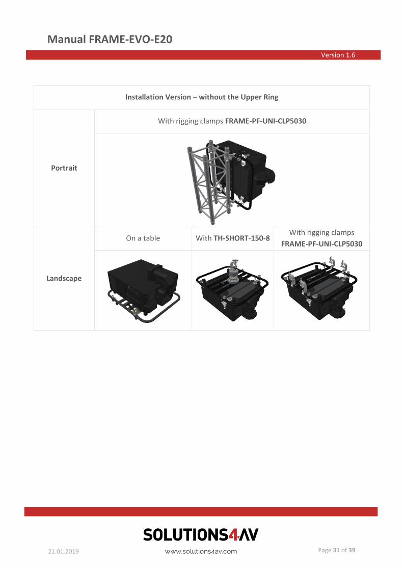
Installation Version – without the Upper Ring
Portrait
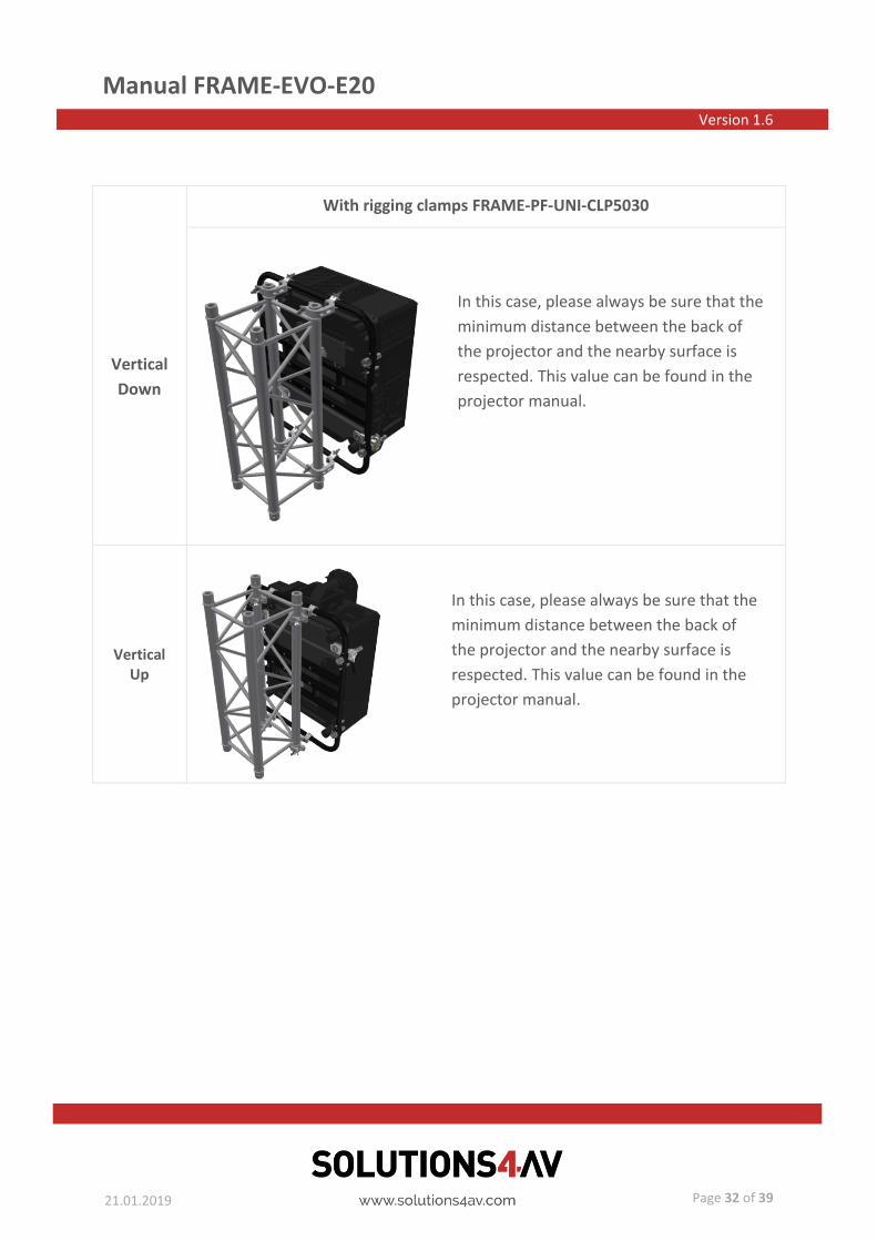
With rigging clamps FRAME-PF-UNI-CLP5030
Landscape
On a table With TH-SHORT-150-8 With rigging clamps
FRAME-PF-UNI-CLP5030
Manual FRAME-EVO-E20 Version 1.6
21.01.2019
Page 32 of 39
Vertical
Down
With rigging clamps FRAME-PF-UNI-CLP5030
Vertical Up
In this case, please always be sure that the
minimum distance between the back of
the projector and the nearby surface is
respected. This value can be found in the
projector manual.
In this case, please always be sure that the
minimum distance between the back of
the projector and the nearby surface is
respected. This value can be found in the
projector manual.

Manual FRAME-EVO-E20 Version 1.6
21.01.2019
Page 33 of 39
12. System maintenance and inspection (Re-examination)
The FRAME-EVO-E20 does not require special maintenance but a visual inspection must be
done prior to every installation in which the system is involved:
• Before and after each installation, the M8 and M10 mounting holes must be
carefully inspected, as they may get damaged during the installation of the hanging
accessory.
• Please carefully examine the M8 and M10 mounting holes by looking inside each one
of them and make sure the thread is not broken or damaged in any way.
• Please make a visual inspection to be sure that all the screws are in the right place
and none are missing.
• Make sure that the screws, nuts, stacking pins, connection rods, mounting plate and
all the components are not bended, damaged, or broken.
• If any parts are broken or missing, please contact the seller so he can provide the
spare parts.

Manual FRAME-EVO-E20 Version 1.6
21.01.2019
Page 34 of 39
• On the three screws + nuts presented on the above picture a red color sealing wax
was applied to be sure that the nuts will always be on the same position and no one
will try to tighten or loosen them.
• Do not try to manipulate the nuts, because the adjustment mechanism can be
blocked and accidents can occur!
• If one notices that the sealing wax is broken or the nut is moved, please contact the
manufacturer!
Bottom view:
Top view:

Manual FRAME-EVO-E20 Version 1.6
21.01.2019
Page 35 of 39
• Except for the situation described on the previous point, please control, with
corresponding tool, that all the other screws are properly tightened.
Do not exchange broken or malfunctioning parts with ones that are not accredited by the
manufacturer because serious injuries and property damage can occur!
The inspection must be done by a qualified person!
One meticulous inspection must be performed every year. For that, a qualified person needs
to carefully check that none of the components are damaged or broken.
Manual FRAME-EVO-E20 Version 1.6
21.01.2019
Page 36 of 39
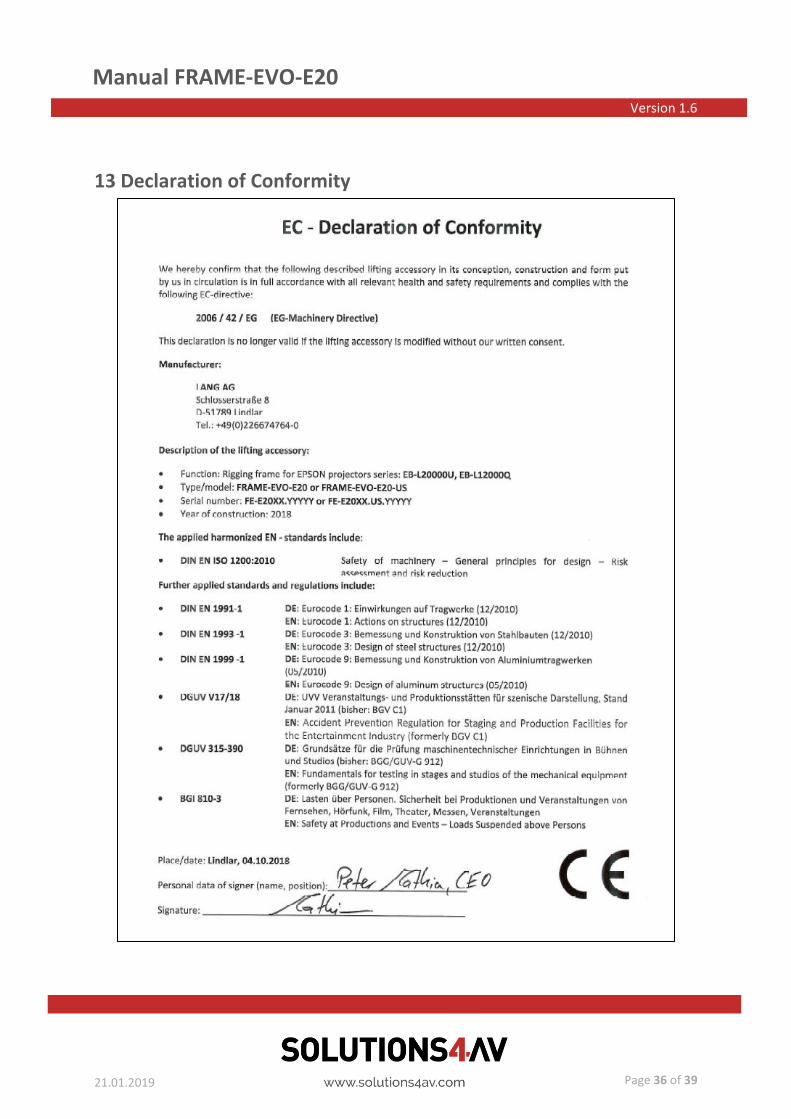
13 Declaration of Conformity

Manual FRAME-EVO-E20 Version 1.6
21.01.2019
Page 37 of 39
14 Dimensions
14.1 FRAME-EVO-E20
Frame weight: 16,2 kg / 35.715 lbs; (only frame)

Manual FRAME-EVO-E20 Version 1.6
21.01.2019
Page 38 of 39
14.2 FRAME-EVO-E20 Installation Version - without the Upper Ring
Frame weight: 11,8 kg / 26.014 lbs; (only frame)
Manual FRAME-EVO-E20 Version 1.6
21.01.2019
Page 39 of 39
Imprint
LANG AG
Schlosserstraße 8
51789 Lindlar
GERMANY
Tel.: +49 2266 4764 0
Fax: +49 2266 4764 43
E-Mail: [email protected]
Web: www.lang-ag.com