framework you will need - absolute distabsolutedist.com/images/cable_application_guide... · please...
TRANSCRIPT


Please contact ADI™ with any questions:Ph: 1-800-335-5909 Web: www.absolutedist.comFax: 800-203-4495 Email: [email protected]
Framework You Will Need for Cable Railing
End Post ConstructionSince hundreds of pounds of tension are being applied to end posts using cable railing, those posts must be substantial enough to handle that tension. For wood posts a minimum 4x4 post is required to keep the post from bending when the cables are tensioned. You will need a top rail, and we recommend that it be reinforced with a support such as a 2x4 on end under the top rail (see illustration at right). End posts must be securely mounted to the deck to prevent the post from coming loose when the cables are tensioned. A bottom rail helps distribute the force away from the bottom of the post, but is not required.Of course, secure mounting of the intermediate posts to the deck is just as important as with end posts.
Intermediate Posts / Cable BracesTo keep the cable from spreading beyond IBC code requirements, we recommend that the cable be supported in some manner no more than every 42” along its run. Intermediate posts, through which the cable is strung, act as supports for the cable. To avoid having to use more intermediate posts than is structurally necessary, an aluminum cable brace with holes for the cables to pass through can be used to support the cables (see illustrations). A typical cable brace is 3/4” x 3/4” square aluminum tube.
Cable SpacingWe recommend that you space the cables with no more than a 3” clear span between the cables (see illustrations). For example, if you are using 1/8” diameter cable, you would drill your holes on center no more than 3-1/8” apart.
Cable Diameter SizesThe most common cable sizes are 1/8” diameter cable and 3/16” diameter cable. 1/8” is used mostly for residential railing systems and maximizes the view that cable is known for. 3/16” Cable is used for commercial rail jobs that require a more heavy duty cable rail application.
2

Warranty: Stainless steel hardware and cable are covered by a limited warranty for a period of ten (10) years from the date of receipt to be free from defects due to defective materials and workmanship.For complete warranty details, please visit http://www.absolutedist.com/images/Warranty.pdf
Please contact ADI™ with any questions:Ph: 1-800-335-5909 Web: www.absolutedist.comFax: 800-203-4495 Email: [email protected]
3
Kit Assemblies for Wood PostsFor level runs:224 Series (outside to outside)
2-3/8” Invisiware® Receiver to Pull-Lock®.
300 Series (inside to inside) Adjust-a-Body® with Hanger Bolt to Push-Lock Lag.
601 Series (inside to outside) 3½” Invisiware® Receiver to Push-Lock Lag.
For stairs, pitched runs:500-W Series (inside to inside)
Push-Lock® with Threaded Eye and Lag Eye to Adjust-a-Body® with Threaded Eye and Lag Eye.
Recommendations for wood railings:Outside attachments can only be used if your end posts are not obstructed on the back side: Series 200; or Series 601 or if only one end is obstructed.If you are unable to access the back side of your end post, then you will need to use a series with an inside attachment: Series 300 or 500 if both ends are obstructed; Series 601 if only one end is obstructed.If you are installing a railing with a pitch, you will need a series that can be run on an angle: 500 Series.
Kit Assemblies For Composite Sleeved Wood Posts
300-C Series (inside to inside) Adjust-a-Body® with Extended Length Hanger Bolt to Push-Lock® with Extended Length Lag.
For stairs using wood posts with composite sleeves: (Outside diameter GREATER than 4-1/2”)500-C Series (inside to inside)
Adjust-a-Body ®with Threaded Eye and Extended Length Lag Eye to Push-Lock® with Threaded Eye and Extended Length Lag Eye.
For level runs using wood posts with composite sleeves. (Outside diameter GREATER than 4-1/2”)

Please contact ADI™ with any questions:Ph: 1-800-335-5909 Web: www.absolutedist.comFax: 800-203-4495 Email: [email protected]
House
INVISIWARE®RECEIVER
Space 3-1/2” Minimum
Single Post Options Cable Options for Post Against a Structure
Fittings that go through the post need at least 3-1/2” of space between the post and the structure to allow for cable to be installed and/or tensioned without issue.
is set less than 3-1/2” from a structure. This
inside of the post and does not require access to the back side of the post.
2. Lag Style Fittings1. Through Post Fittings
LAG FITTINGHouse
Space Less Than 3-1/2”
Cable Options for Intermediate Post
If ever, you need to start and stop cable on
be used. This scenario may occur for very long runs that need to be broken up into multiple sections of cable.
When cable needs to go out of the post at an angle, this can be achieved by a couple methods.
1. Starting and stopping cable at a single post. (Commonly used for Stairs or Sleeved Posts)
2. Running continuous cable and bending cable at post with post protector tube. (not to exceed 45 degrees)
2. Cable Bending at a Single Post1. Shared Line Post
PUSH-LOCK® with
THREADED EYE
LAG EYE
PUSH-LOCK® LAGADJUST-A-BODY®
WITH HANGER BOLT PUSH-LOCK® LAG
4
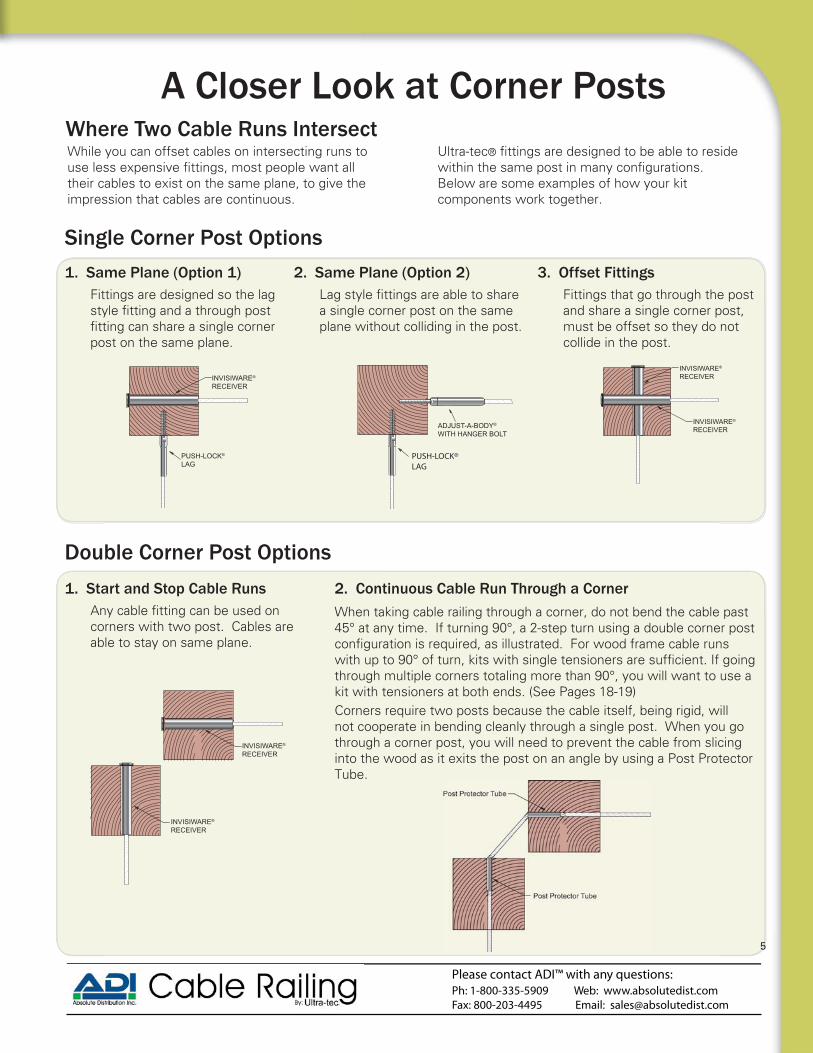
A Closer Look at Corner Posts
While you can offset cables on intersecting runs to
their cables to exist on the same plane, to give the impression that cables are continuous.
®
Below are some examples of how your kit components work together.
Where Two Cable Runs Intersect
2. Continuous Cable Run Through a CornerWhen taking cable railing through a corner, do not bend the cable past 45° at any time. If turning 90°, a 2-step turn using a double corner post
through multiple corners totaling more than 90°, you will want to use a kit with tensioners at both ends. (See Pages 18-19)Corners require two posts because the cable itself, being rigid, will not cooperate in bending cleanly through a single post. When you go through a corner post, you will need to prevent the cable from slicing into the wood as it exits the post on an angle by using a Post Protector Tube.
Single Corner Post Options
INVISIWARE®
RECEIVER
PUSH-LOCK®
LAG
Fittings are designed so the lag
post on the same plane.
1. Same Plane (Option 1)
ADJUST-A-BODY®
WITH HANGER BOLT
PUSH-LOCK®LAG
a single corner post on the same plane without colliding in the post.
2. Same Plane (Option 2)
INVISIWARE®
RECEIVER
INVISIWARE®
RECEIVER
Double Corner Post Options
corners with two post. Cables are able to stay on same plane.
1. Start and Stop Cable Runs
Please contact ADI™ with any questions:Ph: 1-800-335-5909 Web: www.absolutedist.comFax: 800-203-4495 Email: [email protected]
5
INVISIWARE®
RECEIVER
INVISIWARE®
RECEIVER
Fittings that go through the post and share a single corner post, must be offset so they do not collide in the post.
3. Offset Fittings

Please contact ADI™ with any questions:Ph: 1-800-335-5909 Web: www.absolutedist.comFax: 800-203-4495 Email: [email protected]
Decks come in all shapes and sizes, but there are only a few types of cable runs that go on those decks: inside-of-post to inside-of-post, inside-of-post to outside-of-post, and outside-of-post to outside-of-post. The following illustrations represent several ways you can run cable on your deck. Every run will require a
Depending on the length of the run, the tensioning device in the kit, and whether you plan to bend the cable through a corner, you will either be able to use a
Your Deck Typenon-tensioning Push-Lock® or Pull-Lock® on the other end or you will need to use a Push-Lock tensioner on the other end.
The VIP RunYou will see that Run #1 on each drawing is the “view run” — the one that is most important, most visible of all your runs. It’s the one on which you want to have the least interference with the view, so you always start with that run and build around it.
Stained Cedar Rail with Cable
Wood Rail with Cable Redwood Rail with CableAzek Composite Sleeve w/ Cable
6
House
outsidemount
outsidemount
Post Protector Tubes in W ood Posts
3½”min .
Series 224
Deck 2
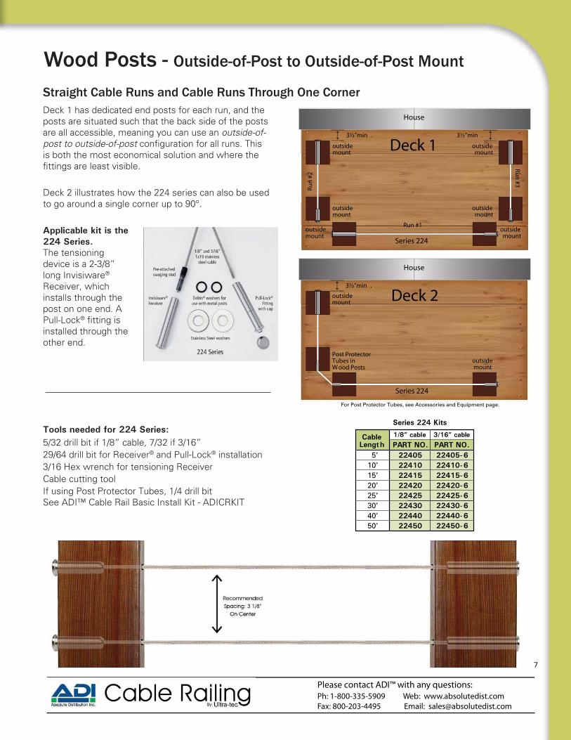
Deck 1 has dedicated end posts for each run, and the posts are situated such that the back side of the posts are all accessible, meaning you can use an outside-of-post to outside-of-postis both the most economical solution and where the
Deck 2 illustrates how the 224 series can also be used to go around a single corner up to 90°.
Applicable kit is the 224 Series. The tensioning device is a 2-3/8” long Invisiware® Receiver, which installs through the post on one end. A Pull-Lock®
installed through the other end.
Wood Posts - Outside-of-Post to Outside-of-Post Mount
Deck 1
Straight Cable Runs and Cable Runs Through One Corner
Tools needed for 224 Series:5/32 drill bit if 1/8” cable, 7/32 if 3/16”29/64 drill bit for Receiver® and Pull-Lock® installation3/16 Hex wrench for tensioning ReceiverCable cutting toolIf using Post Protector Tubes, 1/4 drill bitSee ADI™ Cable Rail Basic Install Kit - ADICRKIT
For Post Protector Tubes, see Accessories and Equipment page.
House
3½”min . 3½”min .
Series 224
outsidemount
outsidemount
outsidemount
outsidemount
outsidemount
outsidemount
Run #1
Run
#2
Run #3
Deck 1
Please contact ADI™ with any questions:Ph: 1-800-335-5909 Web: www.absolutedist.comFax: 800-203-4495 Email: [email protected]
7
Cable Length PART NO. PART NO.
Series 224 Kits
5’10’15’20’25’30’40’50’
2240522410224152242022425224302244022450
22405-622410-622415-622420-622425-622430-622440-622450-6
1/8” cable 3/16” cable

Please contact ADI™ with any questions:Ph: 1-800-335-5909 Web: www.absolutedist.comFax: 800-203-4495 Email: [email protected]
House
insidemount
outsidemount
Post Protector Tubes in Wood Posts
Series 601
Deck 1 has dedicated end posts, but the posts next to the house are too close to access the back side of the posts. Run #1 is outside to outside, so it will take a Series 224 kit. However, for Runs #2 and #3, you will attach to the inside of the posts next to the house and run through the post at the other end.
Deck 2 illustrates how the 601 series can also be used to go around a single corner up to 90°.
Applicable kit is the 601 SeriesThe tensioning device is a 3½” long Invisiware® Receiver, which installs through the wood post on one end. A Push-Lock® Lag is lagged into the other end.
Wood Posts - Inside-of-Post to Outside-of-Post Mount
Deck 2
Straight Cable Runs and Cable Runs Through One Corner
Cable Length PART NO. PART NO.
1/8” cable 3/16” cable
Series 601 Kits
5’10’15’20’25’30’40’50’
60105
60110
60115
60120
60125
60130
60140
60150
60105-6
60110-6
60115-6
60120-6
60125-6
60130-6
60140-6
60150-6
Tools needed for 601 Series:
5/32 drill bit if 1/8” cable, 7/32 if 3/16”29/64 drill bit for Receiver installation3/16 Hex wrench for tensioning Receiver
9/32 drill bit for Push-Lock® Lag installation7/16 wrench for tightening Push-Lock® Lag Cable cutting toolIf using Post Protector Tubes, 1/4 drill bitSee ADI™ Cable Rail Basic Install Kit - ADICRKIT
For Post Protector Tubes, see Accessories and Equipment page.
House
insidemount
outsidemount
insidemount
outsidemount
Series 601
Run #1
Run
#2
Run #3
Deck 1
Series 224
8
House
insidemount
insidemount
Series 300
Post Protector Tubes in W ood Posts
For Post Protector Tubes, see Accessories and Equipment page.
Deck 2
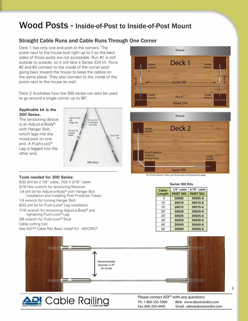
Wood Posts - Inside-of-Post to Inside-of-Post Mount
Deck 1 has only one end post at the corners. The posts next to the house butt right up to it so the back sides of those posts are not accessible. Run #1 is still outside to outside, so it will take a Series 224 kit. Runs #2 and #3 connect to the inside of the corner post going back toward the house to keep the cables on the same plane. They also connect to the inside of the posts next to the house as well.
Deck 2 illustrates how the 300 series can also be used to go around a single corner up to 90°.
Applicable kit is the 300 Series. The tensioning device is an Adjust-a-Body® with Hanger Bolt, which lags into the wood post on one end. A Push-Lock® Lag is lagged into the other end.
Straight Cable Runs and Cable Runs Through One Corner
Tools needed for 300 Series:5/32 drill bit if 1/8” cable, 7/32 if 3/16” cable3/16 Hex wrench for tensioning Receiver 1/4 drill bit for Adjust-a-Body® with Hanger Bolt
installation and installing Post Protector Tubes1/4 wrench for turning Hanger Bolt 9/32 drill bit for Push-Lock® Lag installation 7/16 wrench for tensioning Adjust-a-Body® and
tightening Push-Lock® Lag3/8 wrench for Push-Lock® StudCable cutting toolSee ADI™ Cable Rail Basic Install Kit - ADICRKIT
House
insidemount
insidemount
insidemount
insidemount
Series 300
Run #1
Run
#2
Run #3
Deck 1
Series 224
Please contact ADI™ with any questions:Ph: 1-800-335-5909 Web: www.absolutedist.comFax: 800-203-4495 Email: [email protected]
9
Cable Length PART NO. PART NO.
1/8” cable 3/16” cable
Series 300 Kits
5’10’15’20’25’30’40’50’
30005
30010
30015
30020
30025
30030
30040
30050
30005-6
30010-6
30015-6
30020-6
30025-6
30030-6
30040-6
30050-6

Please contact ADI™ with any questions:Ph: 1-800-335-5909 Web: www.absolutedist.comFax: 800-203-4495 Email: [email protected]
Wood Posts on Stairs - Inside-of-Post to Inside-of-Post Mount
Top posts are often corner posts, which may require the stair run to connect to the inside of the post. The top and bottom of the cable run would be connected perpendicular to those posts, and only the intermediate posts would be drilled on the angle for the cable to run through. The 500-W Series can also be used to go up a stair and across a landing by inserting post protector tubes
The tube will prevent the cable from carving a groove into your post where it exits at an angle.
Applicable kit for wood posts is the 500-W Series. The tensioning device is an Adjust-a-Body® with Threaded Eye, which attaches via mounting screw to the lag eye. A Push-Lock® with Threaded Eye attaches the same way to the other end.
Cable Runs on a Pitch
Tools needed for 500-W Series:5/32 drill bit if 1/8” cable, 7/32 if 3/16”9/32 drill bit for Lag Eye installation7/16 wrench for tensioning Adjust-a-Body®
5/32 Hex wrench to tighten mounting screwsCable cutting toolIf using Post Protector Tubes, 1/4 drill bitSee ADI™ Cable Rail Basic Install Kit - ADICRKIT
5’10’15’20’25’30’40’50’
50005-W
50010-W
50015-W
50020-W
50025-W
50030-W
50040-W
50050-W
50005-6W
50010-6W
50015-6W
50020-6W
50025-6W
50030-6W
50040-6W
50050-6W
Series 500-W Kits for Wood Posts
1/8” cableCable Length PART NO. PART NO.
3/16” cable
Post Protector Tube
500-W Series
Push-Lock® Threaded
Eye
Adjust-A-Body® with Threaded Eye
SC-6 Screw
SC-6 Screw
Lag Eye Lag Eye
1/8” and 3/16” 1x19 stainless
steel cable
Pre-attached swaging ferrule
I:I
10

An alternative to mounting to the inside of the stair posts is to go through both top and bottom end posts. The holes in the end posts, and any intermediate posts, must be drilled on the angle of the stairs.The 224 Series can also be used to go up a stair and across a landing by inserting post protector tubes
The tube will prevent the cable from carving a groove into your post where it exits at an angle.
Applicable kit is the 224 Series. Requires beveled
combo separately from the kit. The tensioning device is a 2-3/8”” long Invisiware® Receiver, which installs through the wood post on one end. A Pull-Lock®
Cable Runs on a Pitch
Wood Posts on Stairs - Outside-of-Post to Outside-of-Post
Tools needed for 224 Series on stairs:5/32 drill bit if 1/8” cable, 7/32 if 3/16”29/64 drill bit for Receiver and Pull-Lock® installation3/16 Hex wrench for tensioning ReceiverCable cutting toolIf using Post Protector Tubes, 1/4 drill bit
See ADI™ Cable Rail Basic Install Kit - ADICRKIT
O:O
Post Protector Tube
(beveled washer/flat washer combo) per kit,
one combo if one end post is on a landing.
See Tools and Essentials section.
Order two BW356
Please contact ADI™ with any questions:Ph: 1-800-335-5909 Web: www.absolutedist.comFax: 800-203-4495 Email: [email protected]
11
Cable Length PART NO. PART NO.
Series 224 Kits
5’10’15’20’25’30’40’50’
2240522410224152242022425224302244022450
22405-622410-622415-622420-622425-622430-622440-622450-6
1/8” cable 3/16” cable

Please contact ADI™ with any questions:Ph: 1-800-335-5909 Web: www.absolutedist.comFax: 800-203-4495 Email: [email protected]
Straight Cable Runs
Deck 1 has wood posts with composite sleeves. For sleeved posts, the recommended
look. Each run must be start and stop at corner posts. All three runs use the same kit.
Applicable kits are the 300 and 300-C Series: If the outside diameter of the composite sleeve is 4½” or LESS, use the 300 Series. The tensioning device is an Adjust-a-Body® with Hanger Bolt, which lags into the wood post on one end. A Push-Lock® Lag is lagged into the other end.If the outside diameter of the composite sleeve is GREATER than 4½”, use the 300-C Series.
with extended length hanger bolt and lag respectively.
Wood Posts with Composite or Aluminum Sleeves Inside-of-Post to Inside-of-Post Mount
House
insidemount
insidemounts
insidemount
insidemounts
Series 300-C
Deck 1
Cable Length PART NO. PART NO.
1/8” cable 3/16” cable
5’10’15’20’25’30’40’50’
30005-C
30010-C
30015-C
30020-C
30025-C
30030-C
30040-C
30050-C
30005-C6
30010-C6
30015-C6
30020-C6
30025-C6
30030-C6
30040-C6
30050-C6
Series 300-C Kits
Sample: Aluminum Sleeves over 4x4 wood post & aluminum top rail
ADJUST-A-BODY®
with EXTENDED HANGER BOLT
PUSH-LOCK®
EXTENDED LENGTH LAG
Gap Between Sleeve and Post
4-1/2”or
Greater
12

Tools needed for 300-C Series (page 12):
5/32 drill bit if 1/8” cable, 7/32 if 3/16” cable
3/16 Hex wrench for tensioning Receiver
1/4 drill bit for Adjust-a-Body® with Hanger Bolt installation and installing Post Protector Tubes
1/4 wrench for turning Hanger Bolt
9/32 drill bit for Push-Lock® Lag installation
7/16 wrench for tensioning Adjust-a-Body® and tightening Push-Lock® Lag
3/8 wrench for Push-Lock® Stud
Cable cutting tool
See ADI™ Cable Rail Basic Install Kit - ADICRKIT
Top posts are often corner posts, which may require the stair run to connect to the inside of the post. The top and bottom of the cable run would be connected perpendicular to those posts, and only the intermediate posts would be drilled on the angle for the cable to run through.
Applicable kits are 500-W or 500-C Series:If the outside diameter of composite sleeve is 4½” or LESS, use the 500-W Series.The tensioning device is an Adjust-a-Body® with Threaded Eye, which attaches via mounting screw to the lag eye. A Push-Lock® with Threaded Eye attaches the same way to the other end.If the outside diameter of composite sleeve is GREATER than 4½”, use the 500-C Series.The tensioning device is an Adjust-a-Body® with Threaded Eye, which attaches via mounting screw to the extended length lag eye. A Push-Lock® with Threaded Eye attaches the same way to the other end.
Cable Runs on a Pitch
Wood Posts with Composite or Aluminum Sleeves For Stairs - Inside-of-Post to Inside-of-Post Mount
5’10’15’20’25’30’40’50’
50005-C
50010-C
50015-C
50020-C
50025-C
50030-C
50040-C
50050-C
50005-6C
50010-6C
50015-6C
50020-6C
50025-6C
50030-6C
50040-6C
50050-6C
Series 500-C Kits for Wood Posts with Composite Sleeves
1/8” cableCable Length PART NO. PART NO.
3/16” cable
I:I
Tools needed for 500-C Series:
5/32 drill bit if 1/8” cable, 7/32 if 3/16”9/32 drill bit for Lag Eye installation7/16 wrench for tensioning Adjust-a-Body®
5/32 Hex wrench to tighten mounting screwsCable cutting toolSee ADI™ Cable Rail Basic Install Kit - ADICRKIT
Please contact ADI™ with any questions:Ph: 1-800-335-5909 Web: www.absolutedist.comFax: 800-203-4495 Email: [email protected]
13

Please contact ADI™ with any questions:Ph: 1-800-335-5909 Web: www.absolutedist.comFax: 800-203-4495 Email: [email protected]
Budget Kits for 1/8" Cable
For level runs:100 Series (outside to outside)
7½” long threaded stud to Pull-Lock®.
For stairs, pitched runs:100 Series (outside to outside)
7½” long threaded stud to Pull-Lock® with beveled washers (BW-.250-32 for stud, BW32-6W for Pull-Lock®).
100 Series
100 Series with beveled washers
Fitting combinations for wood posts
posts are not obstructed on the back side.
itself, being rigid, will not cooperate in bending cleanly through a single post.
than 45° at any post), you will need to prevent the cable from slicing into the wood as it exits the post on an angle by using a Post Protector Tube (see Tools and Essentials section).
need beveled washers for both ends.
Important Notes for Budget Kits:
Warranty: Stainless steel hardware and cable are covered by a limited warranty for a period of ten (10) years from the date of receipt to be free from defects due to defective materials and
workmanship.For complete warranty details, please visit http://www.absolutedist.com/images/Warranty.pdf
the only scenario in which the economical threaded stud kits may be used. The threaded stud kits are even more economical than the 200 series, but the
hide-in-the-post solution. Two jam nuts and some metal thread (all covered by an end cap) will extend beyond the back of the post on one end. A Pull-Lock®
(Takes longer to install than 224 Series cable kit and
For wood posts, the applicable kit is the 100 Series. The tensioning device is a 7½” long threaded stud which installs on the back side of one end post, as shown in Deck 1.
Wood Posts - Outside-of-Post to Outside-of-Post Mount
CableLength PART NO.
5’10‘15’20‘25’30’40’50’
10005
10010
10015
10020
10025
10030
10040
10050
Series 100 Kits
100 Series
Pull-Lock®
Fitting with cap
Stainless Steel washers
Stainless Steel jam nuts Nut
cap
1/8” 1x19 stainless steel
cable
Pre-attached 7½” threaded stud
Deck 1
*Special Order - Allow Two Weeks Lead Time*
House
Series 100
outsidemount
outsidemount
Post Protector Tubes in
W ood Posts
3½”min. 3½”min .
For Post Protector Tubes, see Accessories and Equipment page.
Deck 1
14

Cable Braces
Cedar Rail with Cable
Please contact ADI™ with any questions:Ph: 1-800-335-5909 Web: www.absolutedist.comFax: 800-203-4495 Email: [email protected]
15
Pre-Drilled Aluminum Cable Brace3/4” x 3/4” tube, 42” long for cutting down to any size rail height. Holes pre-drilled at 3-1/8” on center, 13 holes total. For use between structural posts to
brace plugs to attach to top and bottom rail or deck.
Anodized:Order CB-42-AN-AL-13-P
Black: Order CB-42-BL-AL-13-P
Undrilled Aluminum Cable Brace for Stairs3/4” x 3/4” tube, 42” long for cutting down to any size rail height. Comes undrilled
to match cable array.
Anodized:Order CB-42-AN-AL-P
Black:Order CB-42-BL-AL-P
Cable Braces
3-P
3-P
rsong size illed
Cable brace must be used every 42” to
The cable brace is not a structural member of the rail.
estions:
15
Anodized:Order CB-50-AN-12-P
Black:Order CB-50-BL-12-P
Pre-Drilled Aluminum Cable Brace for Stairs3/4” x 3/4” tube, 50” long for cutting down to any size rail height. Comes pre-drilled with 12 slotted and offset holes to match cable array.

Please contact ADI™ with any questions:Ph: 1-800-335-5909 Web: www.absolutedist.comFax: 800-203-4495 Email: [email protected]
Tools and Essentials
Heavy Duty Hanger Bolt Driver1 pc. self-gripping design intended for multiple installations.Order HB6DRIVER/R Ultra-tec Lag Eye and
Extended Length Lag EyeFor attaching an Adjust-A-Body with Threaded Eye or Push-Lock Threaded Eye to a wood Post.Order: LE6 orLE-6L for Extended Length
1/2”
drive
16
Stainless Steel Cleaner and ProtectantDissolve minor corrosion, then leave a protective coating that lasts for months. Includes an 8-oz. spray-on rust and stain remover and a 4-oz. bottle of protectant.Order EZ Clean
Beveled Washers
use on stairways or slopes where you need to drill your end post holes at an angle.
Light Duty Hanger Bolt Driver® with
driving hanger bolts fast and easy. Order: HB6N/R
h
1/2”
drive
Cable Tension GaugesCheck the tension on your cables with these easy-to-use gauges.Order PT-CR for cable diameter of 1/8”, 3/16”
Cable Cutter For burr-free cutting of cable.For light-duty use to cut 1/8” diameter cable, order C-7HIT
Order two of BW356 Beveled Washer/Flat Washer per cable run
Cable ReleaseReleases cable from Push-Lock® and Pull-Lock®
before cables are tensioned. For 1/8” cable only.Order PL-KEY
Stainless Steel Post Protector TubeThe post protector tube is inserted into a wood post where the cable enters/exits the post at an angle tokeep cable from biting into the wood.Order CS-TUBE6 For 1/8” and 3/16” dia. cable
ADI™ Cable Railing
Basic Install KitKit comes with necessary drill bits, tools, and a cut off wheel to properly install cable railing. Order: ADICRKIT
ary t
Cable Gripping Pliers
cable to avoid winding during installation.Order: PLIERS

Please contact ADI™ with any questions:Ph: 1-800-335-5909 Web: www.absolutedist.comFax: 800-203-4495 Email: [email protected]
17
Reviewing the Cable Basics Use minimum 4x4 wood end posts to properly support the cables when tensioned.
Support the end posts with a horizontal top rail installed between the posts.- The bottom rail is optional providing the posts are securely anchored.
Re uires 3 spacing between cables so to not exceed 4 when de ected.
Cable brace must be used every 42 to avoid the cable from de ecting over 4- The cable brace is not a structural member so you can use a variety of
materials for this purpose. (i.e. Aluminum baluster Wood 2 2 Flat bar etc.)
Tension cable runs from the outside-in alternating between top and bottom runs.
Cables are to be tensioned to 3 - 4 lbs per run. - Cable should de ect or less when pushed on in center of run.
3 Rail height will typically take 1 runs of cable 42 rail will take 12 runs of cable - If no bottom rail is being used.
Lag style cable ttings are re uired for cable when using sleeved posts.
If two posts are used on a corner of the deck the cable can run through the corner by making a 45 degree turn through the posts.
- Single tensioner (most common) cable kits allow cable to pass through one corner.- Double tensioner cable kits allow cable to pass through two corners.

Please contact ADI™ with any questions:Ph: 1-800-335-5909 Web: www.absolutedist.comFax: 800-203-4495 Email: [email protected]
House
Series 272
outsidemount
outsidemount
Post Protector Tubes in Wood Posts
Post Protector Tubes in
Wood Posts
3½”min. 3½”min.
For Post Protector Tubes, see Accessories and Equipment page.
Deck 1
For level runs: 272 Series (outside to outside)
3½” Invisiware® Receiver to 1½” Receiver with Push-Lock® Stud.
672 Series (inside to outside) Adjust-a-Body® with Hanger Bolt to 1½” Receiver with Push-Lock® Stud.
371 Series (inside to inside) Adjust-a-Body® with Hanger Bolt to Push-Lock® Turnbuckle with Hanger Bolt.
Cable Runs through Two Corners When going around two corners, it’s necessary to tension the cable from both ends as shown in Deck 1.
Applicable kit is the 272 Series.The tensioning devices are a 3½” long Invisiware® Receiver, which installs through the post on one end, and a Push-Lock® Stud on the other end, which is threaded into a 1½” long Receiver.
Tools needed for 272 Series:5/32 drill bit if 1/8” cable, 7/32 if 3/16”29/64 drill bit for Receiver® and Pull-Lock® installation3/16 Hex wrench for tensioning ReceiverCable cutting toolIf using Post Protector Tubes, 1/4 drill bitIf 272 Series, 3/8 wrench for Push-Lock® Stud
Cable Length PART NO. PART NO.
1/8” cable 3/16” cable
30’40’50’60’
27230
27240
27250
27260
27230-6
27240-6
27250-6
27260-6
Series 272 Kits
Wood Posts - Outside-of-Post to Outside-of-Post Mount
Cable Kits with Double Tensioners
Spe
cial
App
licat
ions
Special Applications
18
Cable Kits Using Two Tensioning FittingsWhen going around two corners, or making multiple turns that equate to more than 90 Degrees, it is required to tension the cable from both ends. If the cable makes more than one 90 degree turn the friction and the angle will keep the cables from being able to be tensioned from a single tensioning end. These cable kits are not recommended for common installations, but provide a solutions for unique installations.

Cable Runs through Two CornersWhen going around two corners, it’s necessary to tension the cable from both ends as shown in Deck 3.
Applicable kit is the 371 Series. The tensioning devices are an Adjust-a-Body® with Hanger Bolt, which lags into the wood post on one end, and Push-Lock® Turnbuckle with Hanger Bolt on the other end.
insidemount
insidemount
House
Series 371
Post Protector Tubes in W ood Posts
Post Protector Tubes in
W ood Posts
Deck 3
1/8” cableCable Length PART NO. PART NO.
3/16” cable
30’40’50’60’
37130
37140
37150
37160
37130-6
37140-6
37150-6
37160-6
Series 371 Kits
Deck 4
When going around two corners, it’s necessary to tension the cable from both ends as shown in Deck 2.
Applicable kit is the 672 series. The tensioning devices are an Adjust-a-Body® with Hanger Bolt which lags into the wood post on one end, and a 1-1/2” long Receiver with Push-Lock® Stud on the other end.
Cable Runs through Two Corners
1/8” cableCable Length PART NO. PART NO.
3/16” cable
30’40’50’60’
67230
67240
67250
67260
67230-6
67240-6
67250-6
67260-6
Series 672 Kits
Wood Posts - Inside-of-Post to Outside-of-Post Mount
Tools needed for 672 Series:5/32 drill bit if 1/8” cable, 7/32 if 3/16”29/64 drill bit for Receiver installation3/16 Hex wrench for tensioning Receiver9/32 drill bit for Push-Lock® Lag installation1/4 drill bit for Adjust-a-Body® installation1/4 wrench for turning Hanger Bolt7/16 wrench to tension Adjust-a-Body®
3/8 wrench for Push-Lock® StudCable cutting tool
Wood Posts - Inside-of-Post to Inside-of-Post Mount
Tools needed for 371 Series:5/32 drill bit if 1/8” cable, 7/32 if 3/16” cable3/16 Hex wrench for tensioning Receiver 1/4 drill bit for Push-Lock® Turnbuckle1/4 wrench for turning Hanger Bolt
3/8 wrench for Push-Lock® StudCable cutting tool
Special A
pplications
House
Post Protector Tubes in W ood Posts
Post Protector Tubes in
W ood Posts
Series 672
outsidemount inside
mount
3½”min .
Deck 2
For Post Protector Tubes, see Accessories and Equipment page.
For Post Protector Tubes, see Accessories and Equipment page.
Special Applications
Please contact ADI™ with any questions:Ph: 1-800-335-5909 Web: www.absolutedist.comFax: 800-203-4495 Email: [email protected]
19

railing systems™
Aluminum Railing and Cable System
Low maintenance aircraft grade aluminum rail system Light weight strong and durable
Sleek contemporary lines Exterior or interior applications
Stocked in Anodized and Black Baked Enamel nish(Bronze and White are Special Order)
Designed and Engineered for use with Cable Pre-drilled posts for simple and fast installation
Nationwide Code Approval Made in USA
1 Year warranty
AS&D™ Product Features
AS&D™ Aluminum Rail and Cable withSeries 200 Aluminum Woodgrain Top Rail
20
Please contact ADI™ with any questions:Ph: 1-800-335-5909 Web: www.absolutedist.comFax: 800-203-4495 Email: [email protected]
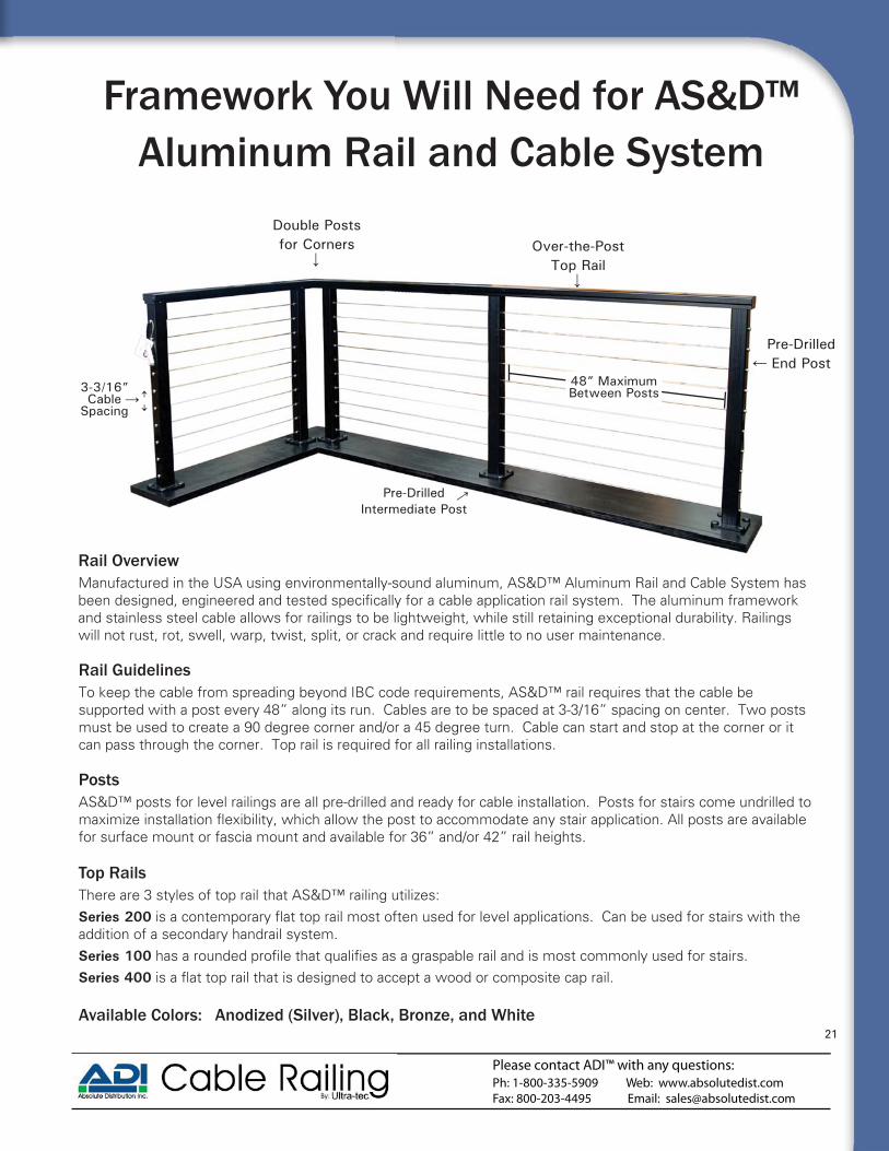
Framework You Will Need for AS&D™ Aluminum Rail and Cable System
Rail Guidelines To keep the cable from spreading beyond IBC code requirements, AS&D™ rail requires that the cable be supported with a post every 48” along its run. Cables are to be spaced at 3-3/16” spacing on center. Two posts must be used to create a 90 degree corner and/or a 45 degree turn. Cable can start and stop at the corner or it can pass through the corner. Top rail is required for all railing installations.
Double Posts for Corners Over-the-Post
Top Rail
Pre-Drilled End Post
Pre-Drilled Intermediate Post
3-3/16”Cable
Spacing
PostsAS&D™ posts for level railings are all pre-drilled and ready for cable installation. Posts for stairs come undrilled to
for surface mount or fascia mount and available for 36” and/or 42” rail heights.
Rail Overview
and stainless steel cable allows for railings to be lightweight, while still retaining exceptional durability. Railings will not rust, rot, swell, warp, twist, split, or crack and require little to no user maintenance.
Top RailsThere are 3 styles of top rail that AS&D™ railing utilizes: Series 200addition of a secondary handrail system.Series 100
Series 400
Available Colors: Anodized (Silver) Black Bronze and White
48” Maximum Between Posts
21
Please contact ADI™ with any questions:Ph: 1-800-335-5909 Web: www.absolutedist.comFax: 800-203-4495 Email: [email protected]

Kit Assemblies for AS&D™ PostsFor level runs:224 Series (outside to outside)
2-3/8” Invisiware® Receiver to Pull-Lock®.
For stairs, pitched runs:224 Series (outside to outside)
2-3/8” Invisiware® Receiver to Pull-Lock®.
2. Continuous Cable Run Through a Single CornerWhen taking cable railing through a corner, do not bend the cable past 45° at any time. When turning 90°, a 2-step
illustrated. AS&D™ railing requires two posts for corners.
corners with two post. Cables are able to stay on same plane.
1. Start and Stop Cable Runs
House
INVISIWARE®RECEIVER
Space 3-1/2” Minimum
End Post and Corner Post Guidelines
1. End Post against a Structure
Fittings that go through the post need at least 3-1/2” of space between the post and the structure to allow for cable to be installed and/or tensioned without issue.
22
Please contact ADI™ with any questions:Ph: 1-800-335-5909 Web: www.absolutedist.comFax: 800-203-4495 Email: [email protected]

AS&D™ Railing System Overview
Surface Mount Post
posts for cable
center or less
finishes - Anodized (Silver), Black, Bronze and White.
Posts
Fascia Mount Post
Series 23-1/2” x 1-7/8” x 8’ Contemporary aluminum top rail. Join multiple rails together with splices to achieve any length required. Field trimmable with carbide blade. Includes bottom
End plate sold separately.
Top Rail Options
Series 4Series 400 aluminum rail cap for attaching wood/composite top rail. Field trimmable with carbide blade.
Series 12” x 1-5/8” x 8’ Aluminum top rail.
handrail when used over the post. Field trimmable with carbide blade. Includes
End plate sold separately.
←
23
Please contact ADI™ with any questions:Ph: 1-800-335-5909 Web: www.absolutedist.comFax: 800-203-4495 Email: [email protected]
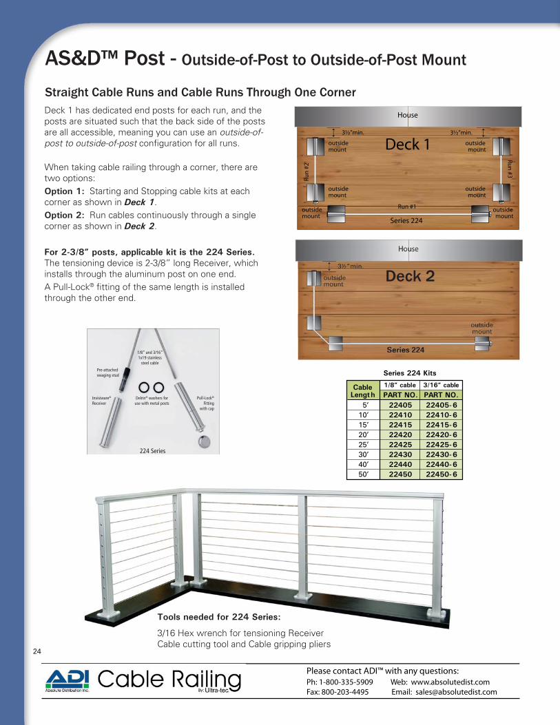
Straight Cable Runs and Cable Runs Through One CornerDeck 1 has dedicated end posts for each run, and the posts are situated such that the back side of the posts are all accessible, meaning you can use an outside-of-post to outside-of-post When taking cable railing through a corner, there are two options: Option 1: Starting and Stopping cable kits at each corner as shown in Deck 1.Option 2: Run cables continuously through a single corner as shown in Deck 2.
For 2-3/8” posts, applicable kit is the 224 Series. The tensioning device is 2-3/8” long Receiver, which installs through the aluminum post on one end. A Pull-Lock®
through the other end.
Deck 1
Deck 2
224 Series
Pull-Lock® Fitting
with cap
1/8” and 3/16” 1x19 stainless
steel cable
Pre-attached swaging stud
Invisiware®
ReceiverDelrin® washers for
use with metal posts
AS&D™ Post - Outside-of-Post to Outside-of-Post Mount
Tools needed for 224 Series:
3/16 Hex wrench for tensioning ReceiverCable cutting tool and Cable gripping pliers
Cable Length PART NO. PART NO.
Series 224 Kits
5’10’15’20’25’30’40’50’
2240522410224152242022425224302244022450
22405-622410-622415-622420-622425-622430-622440-622450-6
1/8” cable 3/16” cable
House
Series 224
3½”min. 3½”min.
outsidemount
outsidemount
outsidemount
outsidemount
outsidemount
outsidemount
Run #1
Run
#2
Run #3
Deck 1
24
Please contact ADI™ with any questions:Ph: 1-800-335-5909 Web: www.absolutedist.comFax: 800-203-4495 Email: [email protected]

AS&D™ Posts for Stairs - Outside-of-Post to Outside-of-Post
Due to many variables in stair applications, stair posts are undrilled to allow maximum flexibility and custom drill hole placement for cables. All stair posts require the addition of a surface mount base plate or fascia bracket for mounting. The holes in the end posts are to be drilled straight through with a 29/64” bit and any intermediate posts must be drilled with offset holes to accommodate to the angle of the stairs using a 3/16” bit.
Cable Runs on a Pitch
Tools needed for 224 Series on stairs:5/32 drill bit if 1/8” cable, 7/32 if 3/16” 3/16 Hex wrench for tensioning Receiver29/64 drill bit for Receiver and Pull-Lock® installation Cable cutting tool
Cable Length PART NO. PART NO.
Series 224 Kits
5’10’15’20’25’30’40’50’
2240522410224152242022425224302244022450
22405-622410-622415-622420-622425-622430-622440-622450-6
1/8” cable 3/16” cable
Deck 1 - Stopping and Starting Cable.Cable Runs are broken into two sections, one for level and the other for stair. This allows for the Series 100 top rail to be used for the stairs, which doubles as a graspable handrail. Deck 2 - Continuous cable from level to stair.Cable runs through a single post at the top of the stairs without stopping. This can be achieved with either a Series 200 or Series 400 top rail. However, these top rails do not qualify as graspable rail and a secondary handrail may be required.
Stair Options
Deck 1Deck 1
Deck 2Deck 2
AS&D ™ Aluminum Rail and Cable - Series 100 Top Rail
For 2-3/8” posts, applicable kit is the 224 Series. The tensioning device is 2-3/8” long Receiver, which installs through the aluminum post on one end. A Pull-Lock®
through the other end.
25
Please contact ADI™ with any questions:Ph: 1-800-335-5909 Web: www.absolutedist.comFax: 800-203-4495 Email: [email protected]

Aluminum Sleeve or Composite Sleeve ApplicationsInside-of-Post to inside-of-Post Mount
Straight Cable Runs
Deck 1 has wood posts with aluminum sleeves. For sleeved posts, the recommended approach
run must be start and stop at corner posts.
Applicable kit are the 300 Series: If outside diameter of the sleeve is 4½” or LESS The tensioning device is an Adjust-a-Body® with Hanger Bolt, which lags into the wood post on one end. A Push-Lock® Lag is lagged into the other end.
Applicable kits are the 300-C Series:If the outside diameter is GREATER than 4½”
with extended length hanger bolt and lag respectively.
House
insidemount
insidemounts
insidemount
insidemounts
Series 300-C
Deck 1
Sample: Solutions™ Aluminum 4 Sleeves & aluminum top rail
over 4x4 wood post.
Dekpro Prestige™ Textured Aluminum 4 Sleeves & aluminum top rail
over 4x4 wood post.
*See page 16 for list of tools needed for installing cable26
Please contact ADI™ with any questions:Ph: 1-800-335-5909 Web: www.absolutedist.comFax: 800-203-4495 Email: [email protected]

Top posts are often corner posts, which may require the stair run to connect to the inside of the post. The top and bottom of the cable run would be connected perpendicular to those posts, and only the intermediate posts would be drilled on the angle for the cable to run through.
Applicable kits are the 500-W Series: If outside diameter of the sleeve is 4½” or LESSThe tensioning device is an Adjust-a-Body® with Threaded Eye, which attaches via mounting screw to the lag eye. A Push-Lock® with Threaded Eye attaches the same way to the other end.
Applicable kits are the 500-C Series: If outside diameter of the sleeve is GREATER than 4½”The tensioning device is an Adjust-a-Body® with Threaded Eye, which attaches via mounting screw to the extended length lag eye. A Push-Lock® with Threaded Eye attaches the same way to the other end.
Cable Runs on a Pitch
Aluminum Sleeve or Composite Sleeve Applicationsfor Stairs - Inside-of-Post to inside-of-Post Mount
end the level run. Series 500W adjustable cable
the stairs. This way the cable enters and leaves the post at the same plane for a consistent look.
Shared Stair Post (Level to Stair)
Tools needed for 500-W Series:5/32 drill bit if 1/8” cable, 7/32 if 3/16”9/32 drill bit for Lag Eye installation7/16 wrench for tensioning Adjust-a-Body®
5/32 Hex wrench to tighten mounting screwsCable cutting toolIf using Post Protector Tubes, 1/4 drill bitSee ADI™ Cable Rail Basic Install Kit - ADICRKIT
500-W Series
Push-Lock® Threaded
Eye
Adjust-A-Body® with Threaded Eye
SC-6 Screw
SC-6 Screw
Lag Eye Lag Eye
1/8” and 3/16” 1x19 stainless
steel cable
Pre-attached swaging ferrule
(500W Series) (300 Series)
*Concept of Installation is the same for both Aluminum Sleeved Posts and Composite Sleeved Posts*
Wood Post w/ Aluminum Sleeve
27
Please contact ADI™ with any questions:Ph: 1-800-335-5909 Web: www.absolutedist.comFax: 800-203-4495 Email: [email protected]
Please contact ADI™ with any questions:Ph: 1-800-335-5909 Web: www.absolutedist.comFax: 800-203-4495 Email: [email protected]
Please contact ADI™ with any questions:Ph: 1-800-335-5909 Web: wwWW w.absolutedist.comFax: 800-203-4495 Email: [email protected]
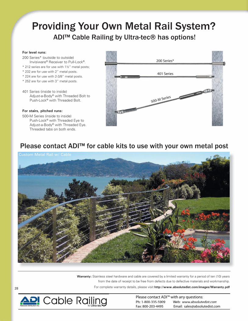
For level runs:200 Series* (outside to outside)
Invisiware® Receiver to Pull-Lock®.* 212 series are for use with 1½” metal posts; * 232 are for use with 2” metal posts.* 224 are for use with 2-3/8” metal posts.* 252 are for use with 3” metal posts.
401 Series (inside to inside) Adjust-a-Body® with Threaded Bolt to Push-Lock® with Threaded Bolt.
For stairs, pitched runs:
Push-Lock® with Threaded Eye to Adjust-a-Body® with Threaded Eye. Threaded tabs on both ends.
Warranty: Stainless steel hardware and cable are covered by a limited warranty for a period of ten (10) years from the date of receipt to be free from defects due to defective materials and workmanship.
For complete warranty details, please visit http://www.absolutedist.com/images/Warranty.pdf
Providing Your Own Metal Rail System?
Please contact ADI™ for cable kits to use with your own metal post
ADI™ Cable Railing by Ultra-tec® has options!
Custom Metal Rail w/ Cable
28

Idea Gallery
Cedar Rail w/ Cable
Composite Sleeves w/ Cable
AS&D™ Fascia Mount Aluminum Rail and Cable - Series 2 Top rail
Redwood Rail w/ Cable using Intermediate Cable Braces
AS&D™ Surface Mount Aluminum Rail and Cable - Series 2 Top rail
Custom Metal Post w/ Cable
Please contact ADI™ with any questions:Ph: 1-800-335-5909 Web: www.absolutedist.comFax: 800-203-4495 Email: [email protected]
Please contact ADI™ with any questions:Ph: 1-800-335-5909 Web: wwWW w.absolutedist.comFax: 800-203-4495 Email: [email protected]
railing lengths, end and corner post locations, stairs and any angles/turns your railing takes. Please include the following:
hat size post?
What material (wood/composite sleeve)?
If composite sleeve, what is the outside diameter when installed?
What is the height of the railing?
Are you using a bottom rail?
Are you using single posts at corners or a double
Do you have 3-1/2” of space behind end posts to allow for installation of Receivers and Pull-Locks®?
What diameter cable are you using? (1/8” typically for residential or 3/16” for commercial)?
3/16” cable - Allow 2-3 week lead time.
Get A Project Quote From Your Dealer
Stainless steel hardware and cable are covered by a limited warranty for a period of ten (10) years from the date of receipt to be free from defects due to defective materials and workmanship.
This warranty does not cover materials which have been abused, neglected or used in any manner other than for pedestrian railings nor for any damage, failure of corrosion resulting from environmental conditions, improper installation, vandalism, insurrection, war or acts of nature.
The company’s obligations are limited to the replacement or refund of the net purchase price of the materials found to be defective and does not cover any other related cost for the disassembly of the defective materials nor the installation costs of the replacement material.
In making a claim the material shall be delivered to ADI™ with a written notice of the defect and evidence that the condition or product failure is covered by this warranty.
Send ADI™ a Drawing and We’ll Do the Take-Off
Email: [email protected]
Fax: 8 -2 3-44 5
Please Include The Following:
Warranty Information
30


Available Thru: