francesco carobolante vice president qualcomm … tuesday pm ec_rf special session/4 ectc... ·...
TRANSCRIPT
Qualcomm Technologies, Incorporated. All Rights Reserved.
Wireless Charging by Magnetic Resonance
ECTC 2014 Wireless Power Transfer Systems
Francesco Carobolante
Vice President – Wireless Power Engineering
Qualcomm Technologies, Inc.

2
Qualcomm Technologies, Incorporated. All Rights Reserved.
Wireless Charging Landscape C
on
ve
nie
nc
e
Long Range: Far-field RF
Short to Medium Range:
Magnetic Resonance
Short Range: Magnetic Induction
Zero Range: Conductive Mat
Coupling of RF energy to a device with a
small receiver antenna
with device in the RF far field
Device is brought within near field of a low
frequency TX antenna. RF energy couples to
device with small receive antenna where it is
rectified for device charging
Coupling of RF energy when a device with
a small receive antenna is placed on a
“charging surface” containing the transmit
elements
Current flows through the pad
to a conductive adapter in the
device

3
Qualcomm Technologies, Incorporated. All Rights Reserved.
Magnetic Resonance vs. Inductive Solutions Key Distinctions – Size, Separation and Orientation
Magnetic Induction (MI)
1:1 ratio of Tx to Rx coil
Tx and Rx coils:
− Are generally closely matched in size and shape
− Are generally in close proximity to each other
− Generally utilize magnets or other mechanism to maintain precise alignment
Magnetic Resonance (MR)
Tx antennas are designed to create a CHARGING AREA or FIELD
Allows devices to charge effectively even when Tx & Rx is separated by 10’s mm
Not impacted by coins, pens, and other metal objects
Doesn’t affect magnetic strip credit cards
No precise alignment required of Rx to Tx
Not just limited to desktop solutions
Rx Coil
Tx Coil
2-4mm
Tx Antenna
Rx Antennas
~10’s of mms

4
Qualcomm Technologies, Incorporated. All Rights Reserved.
MI solutions utilize positioning devices, such as magnets or physical constraints such as blocks or ‘posts’ to insure
alignment.
You cannot place the BT device on the tablet charging spot, and you can’t place the tablet on the smart phone spot and
expect them to charge.
Freedom of Placement Magnetic Induction (MI)
BT Headset
Smart Phone
Tablet w/ Positioning Blocks

5
Qualcomm Technologies, Incorporated. All Rights Reserved.
Flexible coupled solutions do NOT require any alignment devices
One transmitter ‘field’ can charge BT, smart phones, and tablets.
Freedom of Placement Magnetic Resonance (MR)

6
Qualcomm Technologies, Incorporated. All Rights Reserved.
A
Freedom of Design
Each device requires a dedicated transmitter
location where the coil size is reasonably
matched in size or a multi-coil Transmitter is
required
Each device can be placed anywhere on
the transmitter
Must have Tx and Rx coils of comparable size and
dedicated area for each device form factor
Can have a range of antennas for Tx and Rx
therefore supporting form factors as small as
Bluetooth headsets while still supporting
smartphones, netbooks, etc.
MI Systems MR Systems
7
Qualcomm Technologies, Incorporated. All Rights Reserved.
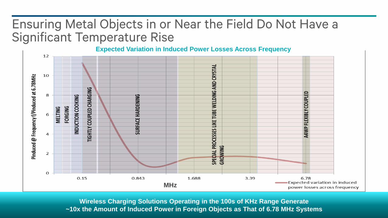
Ensuring Metal Objects in or Near the Field Do Not Have a Significant Temperature Rise
Expected Variation in Induced Power Losses Across Frequency
Wireless Charging Solutions Operating in the 100s of KHz Range Generate
~10x the Amount of Induced Power in Foreign Objects as That of 6.78 MHz Systems
Expected Variation in Induced Power Losses Across Frequency
MHz
8
Qualcomm Technologies, Incorporated. All Rights Reserved.
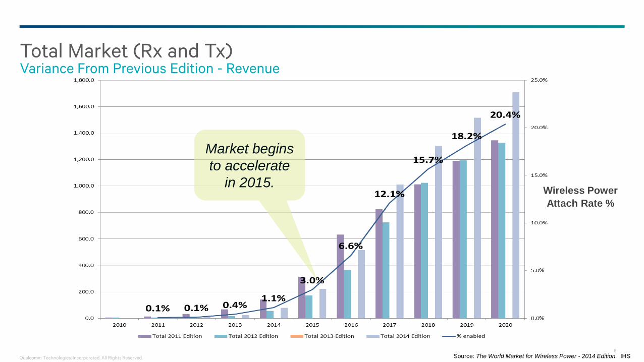
Total Market (Rx and Tx) Variance From Previous Edition - Revenue
Market begins
to accelerate
in 2015. Wireless Power
Attach Rate %
Source: The World Market for Wireless Power - 2014 Edition. IHS

9
Qualcomm Technologies, Incorporated. All Rights Reserved.
Transition To Loosely Coupled Begins in 2015
>5W
Is ~30%
of market Loosely Coupled overtakes
tightly coupled as dominant
technology
Source: The World Market for Wireless Power - 2014 Edition. IHS

10
Qualcomm Technologies, Incorporated. All Rights Reserved.
Wireless Power Receivers Volumes by Application
Source: The World Market for Wireless Power - 2014 Edition. IHS

11
Qualcomm Technologies, Incorporated. All Rights Reserved.
Quick comparison of the Alliances
A4WP PMA WPC
Consumer Brand Rezence Qi
When Established 5/2012 2012 12/2008
Number of Members 101 ~70 ~210
Technology Type Promoted Resonant (MR) Magnetic Induction (MI) Magnetic Induction(MI)
Specification Release 2012 2009 2010
First Product Launch NA 2009 2010
Frequency of power transfer 6.78MHz Variable 80~300KHz ~205KHz
# of devices charged simultaneously 2, 3, more 1 1
Type of devices supported Currently up to 22W Limited to 5W or less Limited to 5W or less
Signaling method OOB – BLE 2.4GHz IB IB
System Efficiency 50-65% 70+% 1:1 ~70% - 1:1 designs,
~60% - coil arrays
Specification Requires EMI/EMC Compliance Yes No No
# of potential generated network harmonics <9 100’s 100’s
Device heating or Foreign Object Concerns No Yes, deploys FOD Yes, deploys FOD

12
Qualcomm Technologies, Incorporated. All Rights Reserved.
Membership 101 MEMBERS
As of June 2, 2014

13
Qualcomm Technologies, Incorporated. All Rights Reserved.
A4WP Latest Developments
Alliance for Wireless Power Unveils Rezence™ Brand Rezence Named Digital
Trends Best of CES 2014 Award Finalist (Top 5!)
A4WP Announces First Rezence Products Following Launch of Global Certification Program
Alliance for Wireless Power and Power Matters Alliance Join Forces
4 companies have certified product:
• Samsung
• Qualcomm
• Gill Electronics
• Samsung Electro-Mechanics

14
Qualcomm Technologies, Incorporated. All Rights Reserved.
Overcoming the Hurdles to Drive Wireless Power into the Mainstream
Meets
User Case
Requirements
Delivers Spatial Freedom (Simultaneously meeting X/Y and Z)
Simultaneous charging of multiple devices from a single specification
Simultaneous charging of multiple device types from a single specification
Meets
Regulatory
Requirements
ICNIRP
FCC Part 15/18
CISPR 11
Meets
Standardization
Requirements
Rezence brand launch by A4WP provides certification of products
for interoperability and safety
Meets
Commercial
Readiness
Requirements
Charge Time, Touch and Battery Temperature Requirements
Mobile Phone Coexistence
Minimal temperature rise in foreign objects in or near the field

15
Qualcomm Technologies, Incorporated. All Rights Reserved.
Ferrite and antenna structures trade-off: thickness vs. permeability
− Magnetic reluctance is given by 𝑅 =𝑙
𝜇𝑤𝑡 , where 𝜇 is the permeability of the material
− Hysteresis losses (given by 𝜇"), which contribute to heating of the assembly
− Complex permeability: 𝜇 = 𝜇′ − 𝑗𝜇“
− Magnetic loss tangent tan 𝛿 =𝜇"
𝜇′
Technology challenges
BATTERY (METAL)
B-field
Magnetic material
Rx antenna
Tx antenna
Quantity Existing Desirable
’r 100-200 >200
”r 1-5 <1
t (mm) 0.4-0.75 0.3
What it takes to operate at 6.78MHz

16
Qualcomm Technologies, Incorporated. All Rights Reserved.
Transmitter: High efficiency, resonant Power Amplifiers from 10 to 50+ Watts
− Low average dissipation, but large instantaneous power loss when off-resonance
− GaN shows some advantage, but dynamic conditions and thermal capacitance are a challenge
Receiver: Rectification at 6.78MHz
− Challenges: high efficiency, low EMI generation
− Synchronous rectification presents some advantages but high voltage required and power dissipation
challenge integration
EMI filters:
− Low losses at 6.78MHz and high rejection at the harmonics and all the way to LTE and WWAN bands
Electronic components’ challenges
17
Qualcomm Technologies, Incorporated. All Rights Reserved.
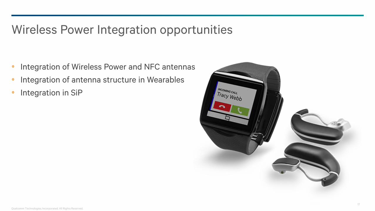
Integration of Wireless Power and NFC antennas
Integration of antenna structure in Wearables
Integration in SiP
Wireless Power Integration opportunities

18
Qualcomm Technologies, Incorporated. All Rights Reserved.
All data and information contained in or disclosed by this document is confidential and proprietary information of Qualcomm
Technologies, Incorporated and all rights therein are expressly reserved. By accepting this material the recipient agrees that this
material and the information contained therein is to be held in confidence and in trust and will not be used, copied, reproduced in
whole or in part, nor its contents revealed in any manner to others without the express written permission of Qualcomm Technologies,
Incorporated.
© 2014 Qualcomm Technologies, Inc. All rights reserved. Qualcomm and WiPower are trademarks of Qualcomm Incorporated, registered in the United
States and other countries. Trademarks of Qualcomm Incorporated are used with permission. Other products and brand names may be trademarks or
registered trademarks of their respective owners.
QUALCOMM Technologies, Incorporated, 5775 Morehouse Drive, San Diego, CA 92121-1714
Thank you