fred r. faxvog, emprimus michael b. marz, american · pdf file-epri el-3295, project 1770-1...
TRANSCRIPT

Visit our website: www.emprimus.com
NOVEMBER 7, 2017
1
Fully operational in theWisconsin Power Grid
MIPSYCON
Operational Experiences of an HV Transformer Neutral Blocking Device
Fred R. Faxvog, EmprimusMichael B. Marz, American
Transmission Co.
SolidGround™GIC Neutral Blocker

The most effective way to block GIC and EMP E3 induced DC currents:
Capacitors block DC current (GIC) while allowing AC current to flow2
• Capacitors placed on the neutral ground connection of Transformers (Neutral Blocking)

Brief History of Neutral Blocking
1983: “A capacitor in the neutral of transformers was determined to be the most effective and practical blocking device.”
-EPRI EL-3295, Project 1770-1 “Mitigation of Geomagnetically Induced and DC Stray Currents”
1992: “…inserting blocking devices in neutral leads appears to be the most logical and effective means of preventing GIC flow.”
“…the use of ordinary capacitors is the best option for a GIC neutral blocking device.”
-EPRI TR-100450 “Proceedings: Geomagnetically Induced Currents Conference”
3
Concern: Having capacitors in the Neutral 100% of the timeprevented utilities from maintaining a solid metallic ground
Electric Power Research Institute (EPRI)

4
• Procedures trend GIC for 20 minutes to verify it is in fact GIC
• If confirmed, turn down generation at sites experiencing or anticipating high GIC in order to maintain voltage control while turning up generation at other locations at higher cost
• Procedures do not decrease the amount of GIC on the Network
• Costs $100’s of millions each year - “Uneconomic” Dispatch
• Increases risk to circuit breaker operation due to a lack of voltage zero crossings
• Will not work for large GMD (“100-year” Solar Super Storm) or nuclear EMP E3 events
“Uneconomic Dispatch”Utilities’ current procedural response to solar storms

• Utility operating procedures do not decrease the amount of GIC in the grid. • GIC and its damaging harmonics continue to flow throughout
the grid and cause issues for utilities and customers
• Reacting to the initial GMD impact is too late
• NOAA and MISO GMD Warning leaves insufficient Margin of Safety
Procedures are not sufficient
5GIC must be blocked to ensure reliable high quality power

GIC must be blocked or significantly reduced to prevent:
• Damage to Customer equipment due to Harmonics• As documented by insurance companies
• Voltage Collapse (Blackout over large areas)• Mis-operation of SVC Capacitor Banks - Inability of capacitor banks to switch
on and off with continual GMD field polarity changes• Damage to Large Power Transformers (LPTs)
• Very long lead times (up to 2 years) to build• Transformers are custom built - 3 different designs for every 4 transformers
built• Damage to Breakers
• High Voltage breakers unable to interrupt Direct Current• Mis-operation of controls
• Damage to Generator Rotors
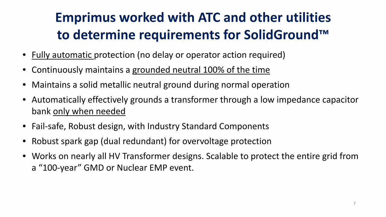
• Fully automatic protection (no delay or operator action required)• Continuously maintains a grounded neutral 100% of the time• Maintains a solid metallic neutral ground during normal operation• Automatically effectively grounds a transformer through a low impedance capacitor
bank only when needed• Fail-safe, Robust design, with Industry Standard Components• Robust spark gap (dual redundant) for overvoltage protection• Works on nearly all HV Transformer designs. Scalable to protect the entire grid from
a “100-year” GMD or Nuclear EMP event.
Emprimus worked with ATC and other utilities to determine requirements for SolidGround™
7

ATC WI and Upper MI Voltage Decrease Map for a 19 V/km Geo-Electric East-West Field.

0.80
0.85
0.90
0.95
1.00
15 17 19 21 23 25 27
Volta
ge a
t Low
est
pu V
olta
ge B
us
Field Strength (V/km)
Baseline, No NBDs One Sub-Station w. one NBD5 Sub-Stations w. NBDs 25 Sub-Stations w. NBDs
Assuming best case scenario:- Peak Power- No contingencies
Grid Collapse
Improvement with Neutral Blocking
ATC Grid Improved Protection Against Voltage Collapse with NBDs
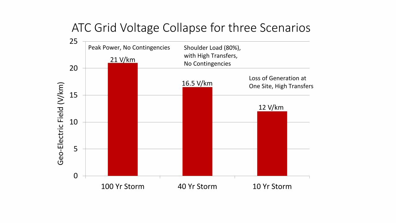
ATC Grid Voltage Collapse for three Scenarios
21 V/km
16.5 V/km
12 V/km
0
5
10
15
20
25
100 Yr Storm 40 Yr Storm 10 Yr Storm
Geo-
Elec
tric
Fie
ld (V
/km
)
Peak Power, No Contingencies Shoulder Load (80%),with High Transfers,No Contingencies
Loss of Generation atOne Site, High Transfers

0
200
400
600
800
1,000
1,200
1,400
1,600
1,800
# 1 # 2 # 3 # 4 # 5 # 6 # 7 # 8 # 9 # 10
Highest Substation GIC Neutral Currents in Wisconsin for a Severe (19 V/km) GMD
Base GIC CurrentTo
tal S
ubst
atio
n N
eutr
al G
IC (A
mps
)
Modeling of GIC Currents for a Severe (19 V/km) GMD at Worst Field Angle (W to E). Modeled Assumptions: Low Power Transfer in Grid and No Outages. Base GIC current is shown in Blue
Modeling Assumptions during Storm Impact:- Low Power Transfers - No Outages
Substations in WI with Highest Neutral GIC Currents

Tota
l Sub
stat
ion
Neu
tral
GIC
(Am
ps)
Substations in WI with Highest Neutral GIC Currents
Modeling of Highest GIC Currents for a Severe (19 V/km) GMD at Worst Field Angle (W to E). Modeled Assumptions: Low Power Transfer in Grid and No Outages. Base GIC currents are shown in Blue and GIC currents after Neutral Blocking at Two Sites (#1 and #10) are shown in Orange.
0
200
400
600
800
1,000
1,200
1,400
1,600
1,800
#1 #2 # 3 # 4 # 5 # 6 # 7 # 8 # 9 # 10
Base GIC Current GIC Current After Blocking at Two Sites
Modeling Assumptions during Storm Impact:- Low Power Transfers - No Outages

Network Priority for Neutral Blocking Devices
Power Network Modeling shows the highest priority locations for the Installation of Neutral Blocking Devices
• Select the substations, five at a time, that have the highest GIC currents for NBDs – then re-run the model
• Typically GSUs followed by the first down-stream Auto-Transformers & SVCs show the highest GIC currents
• All Transformers at a given site should have Neutral Blocking
One NBD device can protect one to three transformers if located together 13
0
500
1,000
1,500
2,000
2,500
3,000
3,500
0 1 2 3 4 5 6 7 8 9 10 11 12 13 14 15
Zion - PleasantPrairie 345 #1Wempletown -Paddock 345 #1Zion - Arcadian345 #1Wempletown -Rockdale 345 #1Eau Claire -Arpin 345 #1
0 10 20 30 40 50 60 70 80 90 100 110 120 130 140 150
Tie
–Lin
e GI
C (A
mps
)
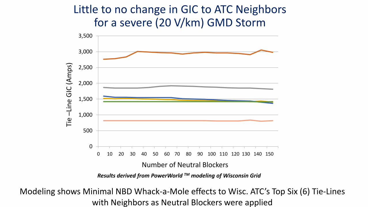
Number of Neutral BlockersResults derived from PowerWorld TM modeling of Wisconsin Grid
Modeling shows Minimal NBD Whack-a-Mole effects to Wisc. ATC’s Top Six (6) Tie-Lines with Neighbors as Neutral Blockers were applied
Little to no change in GIC to ATC Neighborsfor a severe (20 V/km) GMD Storm

Results derived from PowerWorld TM modeling of the Wisconsin ATC Power Grid
% of Transformers with Blocking
% Reduction of Total Network GIC
% Decrease in Reactive (VAR) Consumption
7 % 13.7 % 14.6 %
14 % 27.3 % 29.3 %
21 % 41.0 % 43.7 %
• Significantly reduces Total Network GIC
• Significantly reduces Harmonics in the network
• Significantly reduces Reactive Power (VAR) consumption
• Minimizes the “Whack-a-Mole” effects
• Reduces the potential for Voltage Collapse
Benefits of Reducing Total Network Geomagnetic Induced Current (GIC) in the Wisconsin ATC Power Grid
Neutral Blocking on 10% to 20% of HV & EHV Transformers:
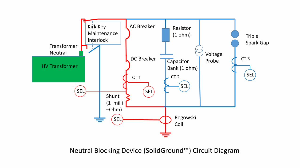
Transformer Neutral
Capacitor Bank (1 ohm)HV Transformer
Shunt (1 milli –Ohm)
Resistor(1 ohm)
DC Breaker
AC Breaker
CT 1
SEL
CT 3
SEL
SELCT 2
VoltageProbe
SEL
Triple Spark Gap
Rogowski Coil
SEL
Kirk KeyMaintenance Interlock
Neutral Blocking Device (SolidGround™) Circuit Diagram
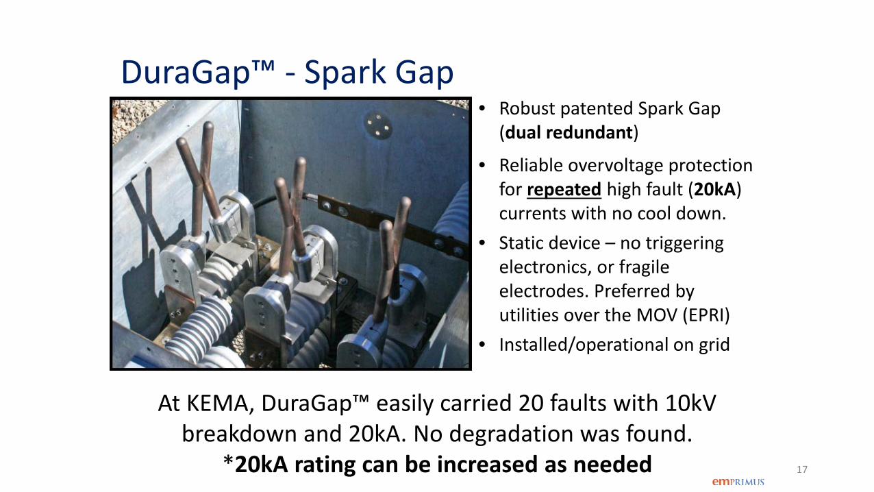
DuraGap™ - Spark Gap• Robust patented Spark Gap
(dual redundant)
• Reliable overvoltage protection for repeated high fault (20kA) currents with no cool down.
• Static device – no triggering electronics, or fragile electrodes. Preferred by utilities over the MOV (EPRI)
• Installed/operational on grid
17
At KEMA, DuraGap™ easily carried 20 faults with 10kV breakdown and 20kA. No degradation was found.
*20kA rating can be increased as needed

DuraGap™ test at KEMA
18

Helping to keep the lights on,
businesses running
and communities strong®
Operational Experiences of an HV Transformer Neutral Blocking DeviceMichael B. Marz, Principal Transmission Planning Engineer
53rd Annual Minnesota Power System Conference November 7, 2017, St. Paul, MN

American Transmission Company
20
•First multi-state, transmission-only USA utility (2001)
•69 kV to 345 kV •>9600 miles of lines •548 substations •Operate Reliably & Plan Economically for Future Load and Generation

Why Did ATC Buy an NBD in 2013?• Concern About GIC on Our System
• Northerly Location (Igneous Rock)• New Long High Voltage Lines• Area Geology (High R Soils)• System Discontinuities• Results of Previous GMD Study
• Coming Regulations (TPL-007)• Improved Analysis Tools and Understanding
of System and Equipment Vulnerabilities• If a Corrective Action Plan Needed, NBD
would be One More Tool Available• Need to Understand Technology and Application
21

• Remote from Generation (Limit GSU Effects)
• Long (160 miles) Radial 345 kV Line Connection
• Only One Transformer at Substation
• Historically High GIC Levels
22
Selecting NBD Substation/Location

Operational in February 2015• 25’ from 345/138
kV, 300 MVA Autotransformer
• Connected Between Transformer Neutral & Ground Grid
• Control Signals to Control House and EMS
23

Bought in 2013 – Operational in 2015•Bought Prototype, Installed Commercial
• Operations, Commissioning, Protection, Construction, etc., Input
•Enhancements• Voltage Probe• Grounding• Spark Gap Replaced MOVs• Bypass Switch Position Indicators• Major and Minor Alarms Defined
24
Acceptance Testing/Commissioning
•Simulator Used to Validate Software• Normal Conditions (Enter/Exit Blocking Mode)• Contingencies and Failures Modeled
• Failed Breakers, Faults, Unbalanced Current, loss of Transformer Neutral, etc.
•Field Tests Confirmed• Sensors Properly Connected• Control Center Communications
•Operated In Automatic Response Mode25

EMS View of the NBD
26
• Operators Monitor, But Don’t Activate• ATC Monitors Transformer Neutral Currents

June 22, 2015 Operation
• GIC > 5 A for 5 Seconds Blocking Mode Triggered• Out of Blocking Mode After 10 Minutes if V < 8 V
27
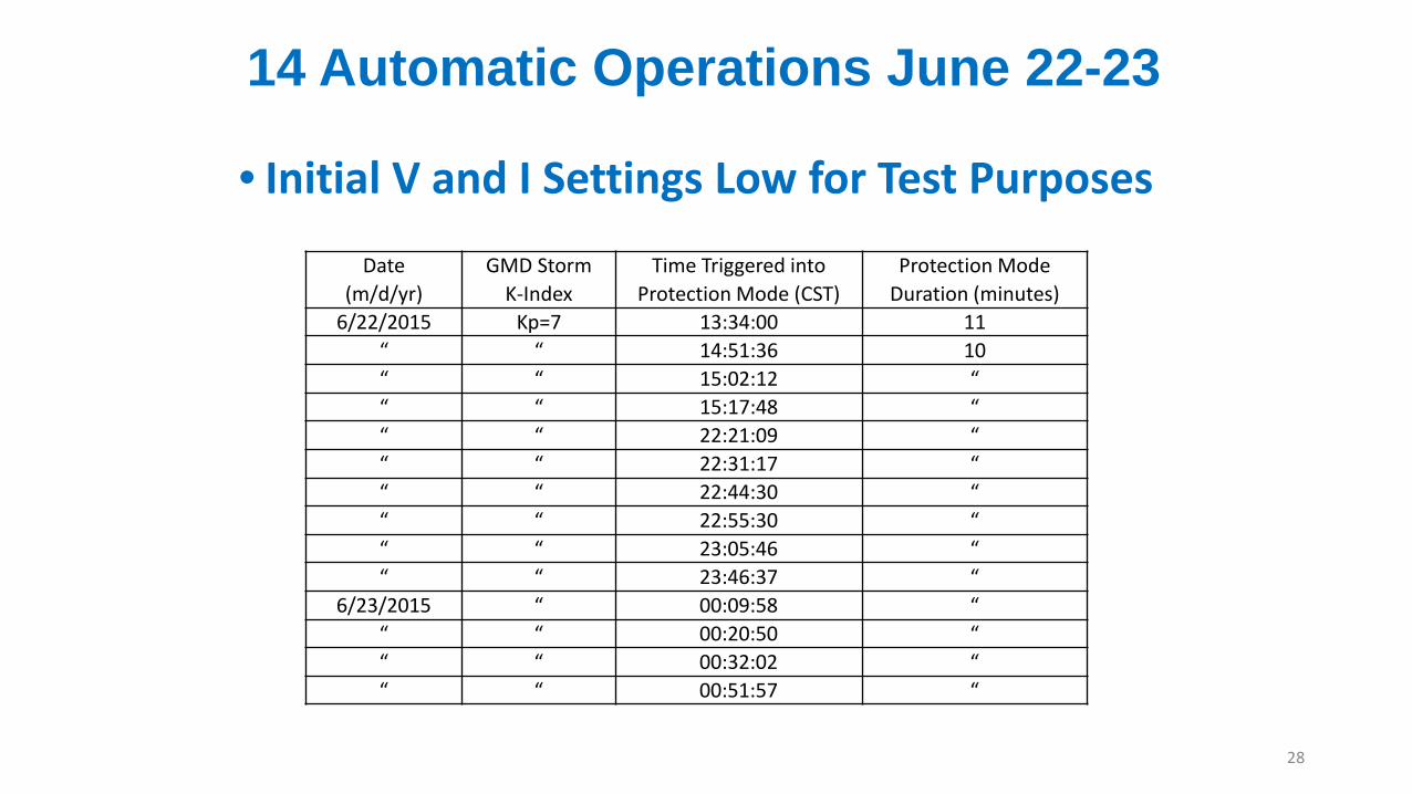
14 Automatic Operations June 22-23
• Initial V and I Settings Low for Test Purposes
28
Date (m/d/yr)
GMD Storm K-Index
Time Triggered into Protection Mode (CST)
Protection Mode Duration (minutes)
6/22/2015 Kp=7 13:34:00 11“ “ 14:51:36 10“ “ 15:02:12 ““ “ 15:17:48 ““ “ 22:21:09 ““ “ 22:31:17 ““ “ 22:44:30 ““ “ 22:55:30 ““ “ 23:05:46 ““ “ 23:46:37 “
6/23/2015 “ 00:09:58 ““ “ 00:20:50 ““ “ 00:32:02 ““ “ 00:51:57 “
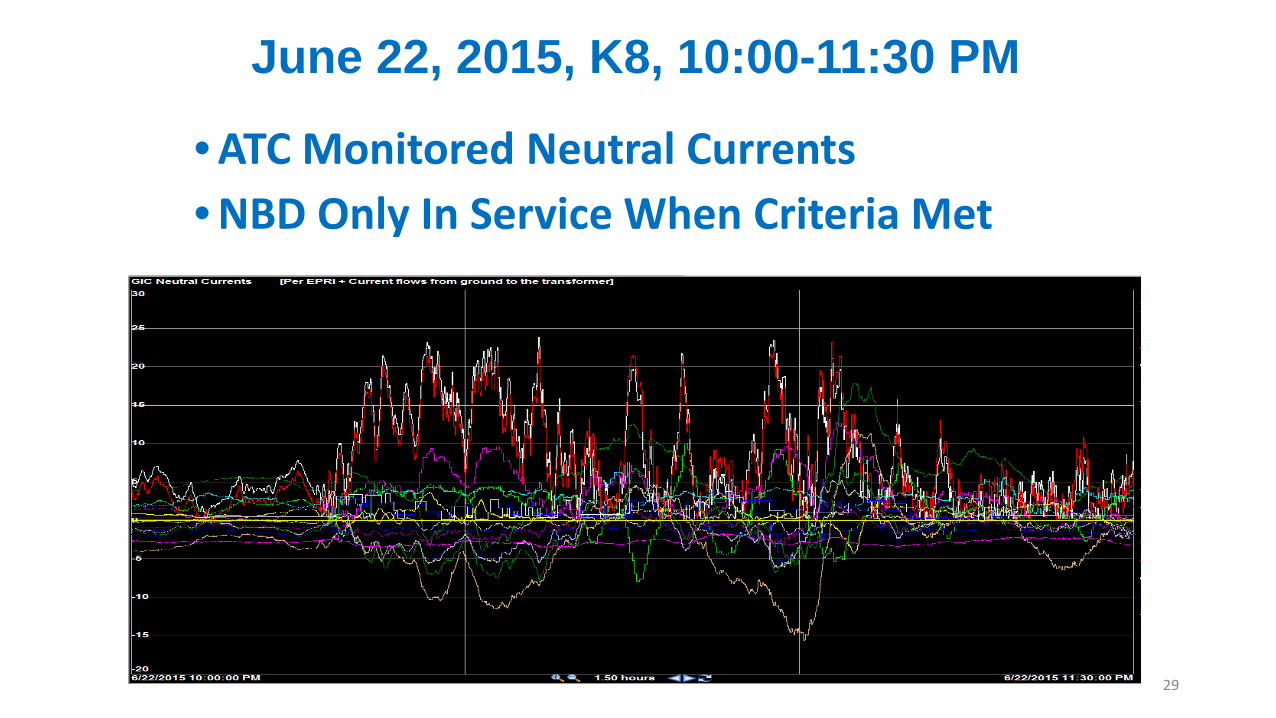
June 22, 2015, K8, 10:00-11:30 PM
29
• ATC Monitored Neutral Currents • NBD Only In Service When Criteria Met
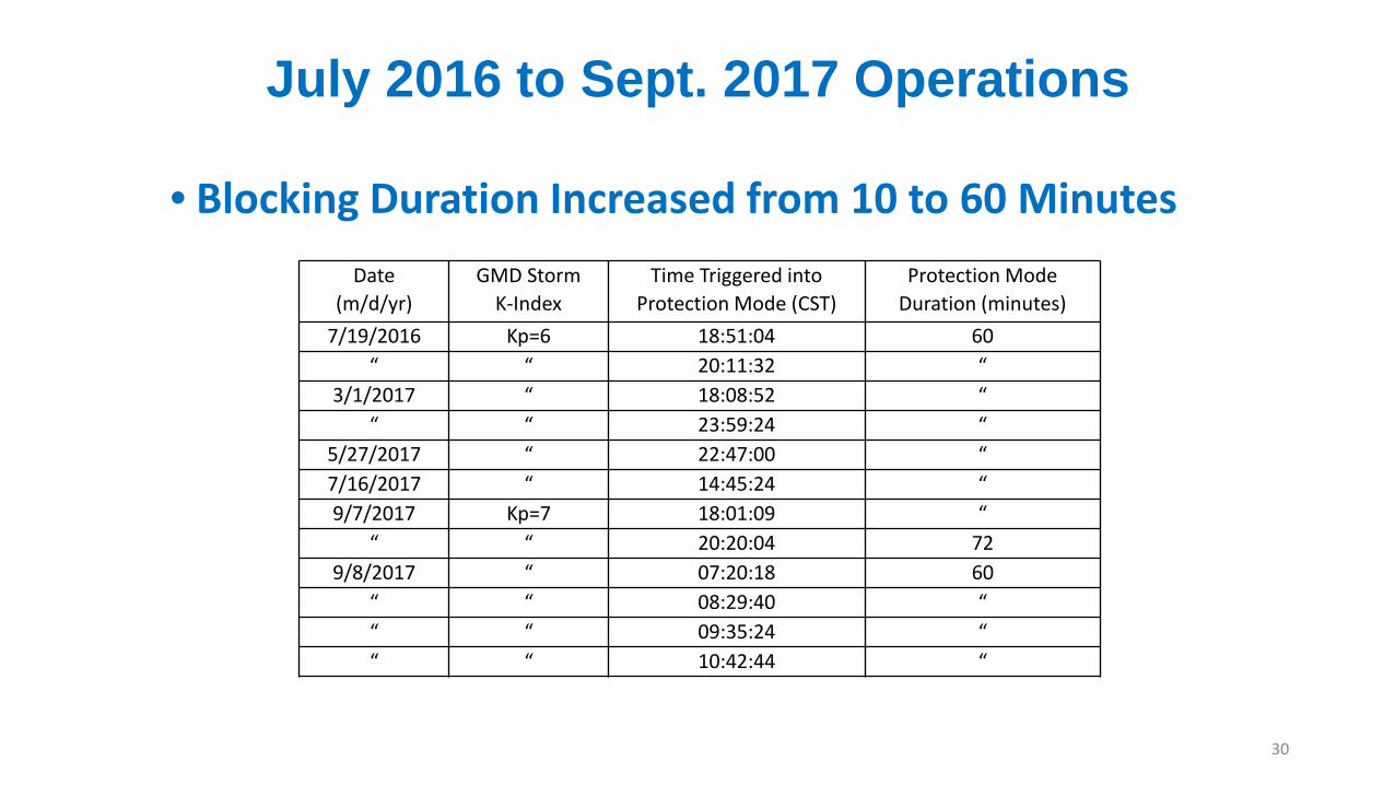
July 2016 to Sept. 2017 Operations
• Blocking Duration Increased from 10 to 60 Minutes
30
Date (m/d/yr)
GMD Storm K-Index
Time Triggered into Protection Mode (CST)
Protection Mode Duration (minutes)
7/19/2016 Kp=6 18:51:04 60“ “ 20:11:32 “
3/1/2017 “ 18:08:52 ““ “ 23:59:24 “
5/27/2017 “ 22:47:00 “7/16/2017 “ 14:45:24 “9/7/2017 Kp=7 18:01:09 “
“ “ 20:20:04 729/8/2017 “ 07:20:18 60
“ “ 08:29:40 ““ “ 09:35:24 ““ “ 10:42:44 “

May 27, 2017, No “Whack-a-Mole”
31
• GIC Drop at NBD Location – No Increase Elsewhere
2 0 1
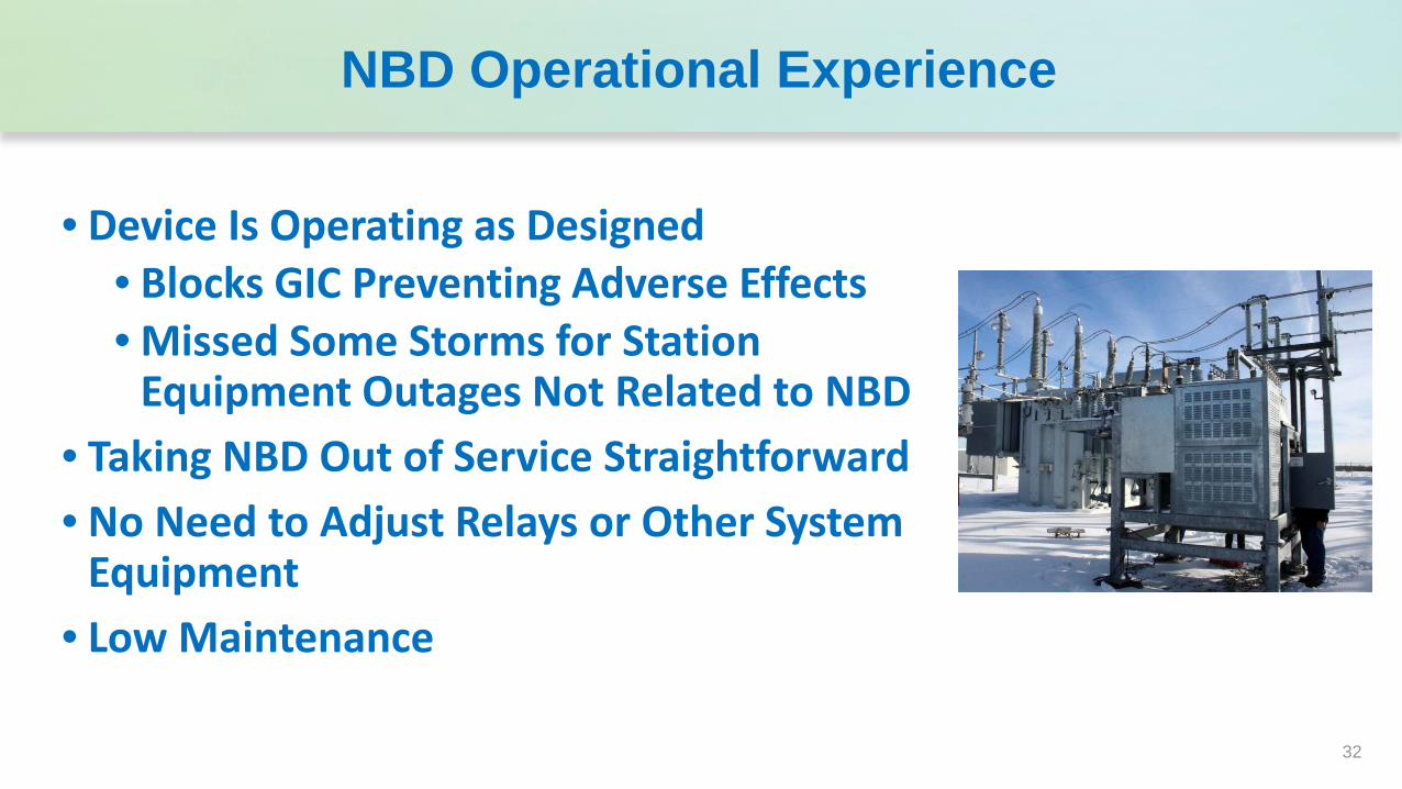
NBD Operational Experience
2 0 16
32
• Device Is Operating as Designed• Blocks GIC Preventing Adverse Effects• Missed Some Storms for Station
Equipment Outages Not Related to NBD• Taking NBD Out of Service Straightforward• No Need to Adjust Relays or Other System
Equipment• Low Maintenance

For more information please contact Fred Faxvog: [email protected]
or Michael Marz: [email protected]
and visit us:
Booth # 408www.emprimus.com
Thanks for Your Attention

Backup Slides

SolidGround™High Voltage Transformer: 300 MVA, 345 kV /138 kV
SolidGround™ Neutral Blocking Device Installed and Operational at a Northern Wisconsin ATC Substation

Selection of NBD Installation Site, Acceptance Testing and Commissioning
• Sight Selection Criteria:• Substation that supplies bulk power to the Upper Peninsula of Michigan• Substation Remote from generation sites• Connecting transmission line that historically experienced significant GIC flows• Substation with only one transformer
• Acceptance Testing and Commissioning• Software testing was validated using an NBD electric model simulator • Commissioning included simulating the NBD and software through a list of potential
operation and contingency conditions • Communications and sensor data connections to the controller were also verified
-2.00
-1.00
0.00
1.00
2.00
3.00
4.00
5.00
6.00
7.00
8.00
9.00
0.00 2.00 4.00 6.00 8.00 10.00 12.00 14.00 16.00 18.00
Shunt Resistor DC Current (Amps) DC Voltage (Volts)
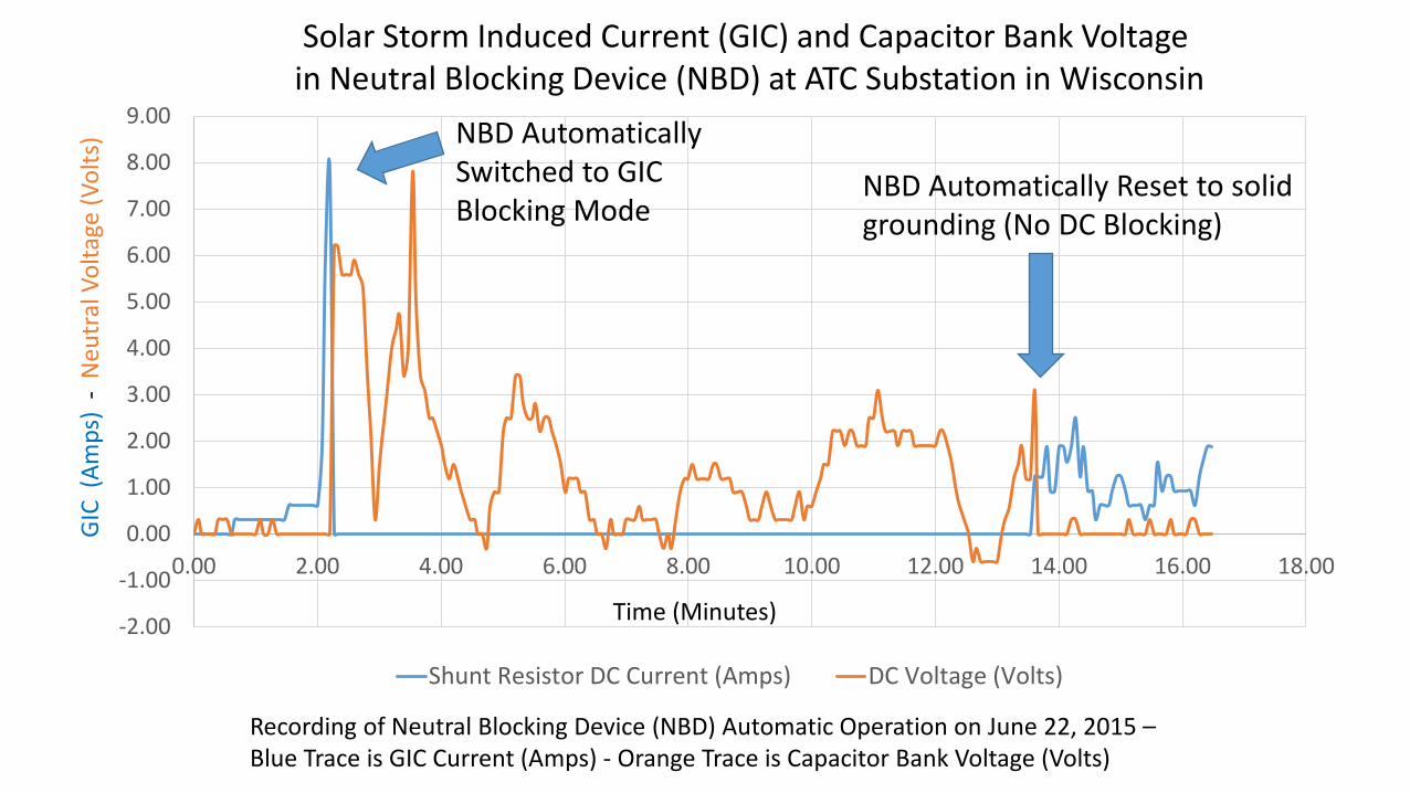
Recording of Neutral Blocking Device (NBD) Automatic Operation on June 22, 2015 –Blue Trace is GIC Current (Amps) - Orange Trace is Capacitor Bank Voltage (Volts)
GIC
(Am
ps)
-N
eutr
al V
olta
ge (V
olts
)
Time (Minutes)
Solar Storm Induced Current (GIC) and Capacitor Bank Voltage in Neutral Blocking Device (NBD) at ATC Substation in Wisconsin
NBD Automatically Switched to GIC Blocking Mode
NBD Automatically Reset to solid grounding (No DC Blocking)

Table I – NBD Automatic GMDProtection Operations - June 2015
Date (m/d/yr)
GMD Storm K -Index †
SG Triggered into Protection Mode
CST Duration in Protection
Mode (Min.)6/22/2015 Kp = 7 13:34:00 11
" 14:51:36 10" 15:02:12 "" 15:17:48 "" 22:21:09 "" 22:31:17 "" 22:44:30 "" 22:55:30 "" 23:05:46 "" 23:46:37 "
6/23/2015 00:09:58 "" 00:20:50 "" 00:32:02 "" 0:51:57 "
14 Protection Operations in June 2015

Table II- NBD Automatic GMD Protection Operations -July 2016 to Oct 2017
Date (m/d/yr)
GMD Storm K - Index †
SG Triggered into Protection Mode CST
Duration in Protection Mode (Min.)
7/19/2016 Kp = 6 18:51:04 6020:11:32 60
3/1/2017 Kp = 6 18:08:52 603/1/2017 23:59:24 "
5/27/2017 Kp = 6 22:47:00 60
7/16/2017 Kp = 6 14:45:24 60
9/7/2017 Kp = 7 18:01:09 60" 20:20:04 72
9/8/2017 7:20:18 60" 8:29:40 "" 9:35:24 "" 10:42:44 "
12 Protection Operations June 2016 thru Sept 2017