free-electron lasers - cern · the physics of free electron lasers by saldin, schneidmiller and...
TRANSCRIPT

Free-electron lasers
Peter SchmuserInstitut fur Experimentalphysik, Universitat Hamburg, Germany
AbstractThe synchrotron radiation of relativistic electrons in undulator magnets and thelow-gain Free-Electron Laser (FEL) are discussed in some detail. The high-gain FEL based on the principle of Self Amplified Spontaneous Emission istreated on a qualitative level.
1 IntroductionThe Free-Electron Laser (FEL) principle has been known since the early 1970’s but for many yearsFEL’s have played a marginal role in comparison with conventional lasers. Only in recent years it hasbecome clear that these devices have the potential of becoming exceedingly powerful light sources inthe vacuum-ultraviolet (VUV) and X ray regime. In my talk I will first deal with undulator radiationsince it is intimitely related to FEL radiation, then explain the low-gain FEL and finally treat the high-gain FEL based on the principle of Self Amplified Spontaneous Emission (SASE). SASE-FEL’s arefrequently considered as the fourth generation of accelerator-based light sources. In contrast to existingsynchrotron radiation light sources which are mostly storage rings the FEL requirements on the electronbeam quality in terms of low transverse emittance and small energy spread are so demanding that onlylinear accelerators can be used to provide the drive beam.
In my one-hour talk it was not possible to go much into mathematical details. The high-gain FELis therefore treated only qualitatively. For a thorough presentation of SASE FEL’s I refer to the book“The Physics of Free Electron Lasers” by Saldin, Schneidmiller and Yurkov and to the lectures by J.Rossbach at the CERN Accelerator School on Synchrotron Radiation.
1.1 Electron accelerators as light sourcesIn the bending magnets of a high-energy circular accelerator the relativistic electrons emit synchrotronradiation. For a Lorentz factor1 γ = W/(mec
2) 1 the radiation is emitted almost tangentially to thecircular orbit. The frequency spectrum is continuous and extends from zero to frequencies beyond the“critical frequency”
ωc =3cγ3
2R(1)
where R is the radius of curvature in the bending magnet. The radiation power is
Prad =e2c
6πε0γ4
R2. (2)
In modern synchrotron light sources the radiation used for research is produced in wiggler or undu-lator magnets which are periodic arrangements of many short dipole magnets of alternating polarity.The electrons move on a wavelike orbit through such a magnet (Fig. 1) but the overall deflection of thebeam is zero. Undulator radiation is far more useful than bending-magnet radiation because it is nearlymonochromatic and concentrated in a narrow angular cone with an opening angle of about ±1/γ. Thewavelength can be estimated from the following consideration. Call λu the period of the magnet ar-rangement. In a coordinate system moving with the average speed of the beam, the relativistic lengthcontraction reduces the period to λ∗u = λu/γ, and the electrons oscillate at a correspondingly higher
1The total relativistic energy of the electron is denoted by W since in this article the letter E is reserved for electric fields.
477

Fig. 1: Schematic representation of undulator radiation. For simplicity the alternating magnetic field and thecosine-like electron orbit have been drawn in the same plane.
frequency ω∗ = 2πc/λ∗u = γ 2πc/λu and emit dipole radiation. If one Lorentz-transforms this radiationinto the laboratory system one gets for the light wavelength λ` ≈ λ∗u/γ = λu/γ
2; for example, for aLorentz factor γ = 1000 (an electron energy of 511 MeV) the radiation wavelength is a million timesshorter than the undulator period. Moreover, the wavelength can be easily varied by changing the particleenergy.
It is interesting to note that the total energy radiated by a relativistic electron in an undulator is the sameas that in a bending magnet of equal magnetic length, however, the intensity is concentrated in a narrowspectral range. Different electrons radiate independently in bending magnets as well as in undulators,hence the total power produced by a bunch of N electrons is simply N times the radiation power of oneelectron.
1.2 Free-electron and conventional lasersThe next big improvement is given by the Free-Electron Laser. The main component is again an undulatormagnet but by means of a clever mechanism (explained below) one forces a large number of electronsto emit their radiation coherently. Like undulator radiation, the FEL radiation is almost monochromaticand well collimated but the power will be N times higher if one manages to achieve full coherence in thebunch.
A conventional laser (Fig. 2) consists of three basic components: the laser medium with at least 3 energylevels, an energy pump which creates a population inversion, and an optical resonator. The electrons arebound to atomic, molecular or solid-state levels, so one may call this a “bound-electron” laser in contrastto the free-electron laser where the electrons move in vacuum. In an FEL (Fig. 3 ) the role of the activelaser medium and the energy pump are both taken over by the relativistic electron beam. An opticalcavity is no longer possible for wavelengths below 100 nm, because the reflectivity of metals and othermirror coatings drops quickly to zero at normal incidence. Here one has to rely on the principle of SelfAmplified Spontaneous Emission (SASE) where the laser gain is achieved in a single passage of a verylong undulator magnet. The schematic setup of a SASE FEL is shown in Fig. 4. One big advantage of anFEL in comparison with a conventional laser is the free tunability of the wavelength by simply changingthe electron energy.
2
P. SCHMUSER
478
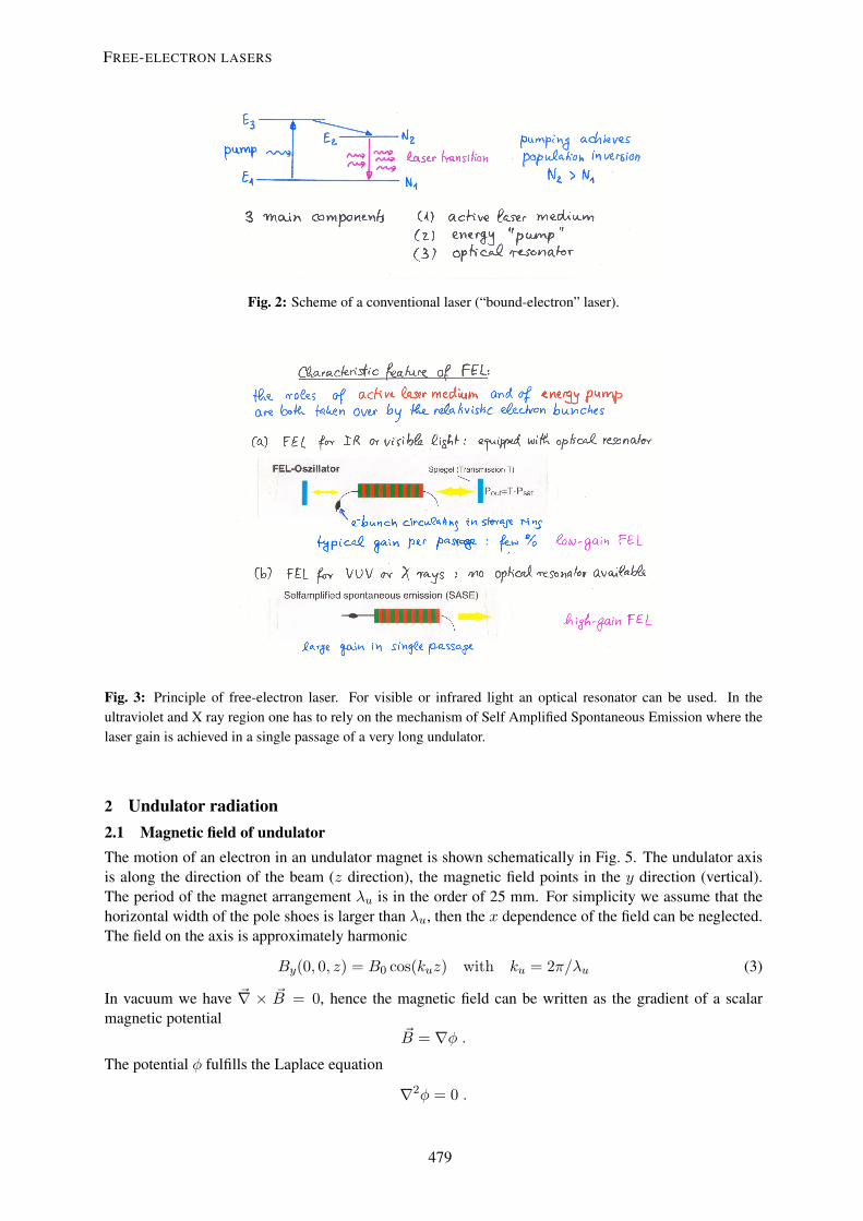
Fig. 2: Scheme of a conventional laser (“bound-electron” laser).
Fig. 3: Principle of free-electron laser. For visible or infrared light an optical resonator can be used. In theultraviolet and X ray region one has to rely on the mechanism of Self Amplified Spontaneous Emission where thelaser gain is achieved in a single passage of a very long undulator.
2 Undulator radiation2.1 Magnetic field of undulatorThe motion of an electron in an undulator magnet is shown schematically in Fig. 5. The undulator axisis along the direction of the beam (z direction), the magnetic field points in the y direction (vertical).The period of the magnet arrangement λu is in the order of 25 mm. For simplicity we assume that thehorizontal width of the pole shoes is larger than λu, then the x dependence of the field can be neglected.The field on the axis is approximately harmonic
By(0, 0, z) = B0 cos(kuz) with ku = 2π/λu (3)
In vacuum we have ~∇ × ~B = 0, hence the magnetic field can be written as the gradient of a scalarmagnetic potential
~B = ∇φ .The potential φ fulfills the Laplace equation
∇2φ = 0 .
3
FREE-ELECTRON LASERS
479

Fig. 4: Schematic of the SASE FEL at the TESLA Test Facility.
y
x
z e
PermanentMagnet
Pole
Gap
Fig. 5: Schematic view of an undulator magnet with alternating polarity of the magnetic field and of the cosine-liketrajectory of the electrons. The distance between two equal poles is called the undulator period λu.
Making the ansatz
φ(y, z) = f(y) cos(kuz) ⇒ d2f
dy2− k2
uf = 0
we get for the general solution
f(y) = c1 sinh(kuy) + c2 cosh(kuy) ,
By(y, z) =∂φ
∂y= ku(c1 cosh(kuy) + c2 sinh(kuy)) cos(kuz) .
The vertical field component By is symmetric with respect to the plane y = 0 hence c2 = 0, andmoreover kuc1 = B0. So the potential is
φ(x, y, z) =B0
kusinh(kuy) cos(kuz) . (4)
4
P. SCHMUSER
480

For y 6= 0 the magnetic field has also a longitudinal component Bz .
Bx = 0By = B0 cosh(kuy) cos(kuz) (5)
Bz = −B0 sinh(kuy) sin(kuz) .
In the following we restrict ourselves to the symmetry plane y = 0.
2.2 Electron Motion in an Undulator2.2.1 Trajectory in first orderWe call W = Ekin + mec
2 = γmec2 the total relativistic energy of the electron. The transverse
acceleration by the Lorentz force isγme~v = −e~v × ~B . (6)
This results in two coupled equations
x =e
γmeBy z z = − e
γmeByx (7)
which are solved iteratively. To obtain the first-order solution we observe that vz = z ≈ v = β c = constand vx vz . Then z ≈ 0 and
x(t) ≈ − eB0
γmeβck2u
cos(kuβct) , z(t) ≈ βct . (8)
The electron travels on a cosine-like trajectory
x(z) = −A cos(kuz) with A =eB0
γmeβck2u
.
The maximum divergence angle is
θmax ≈[dx
dz
]max
=eB0
γmeβcku=K
βγ
Here we have introduced the undulator parameter
K =eB0
mecku=eB0λu
2πmec. (9)
Synchrotron radiation of relativistic electrons is emitted inside a cone with opening angle 1/γ. If theparticle trajectory stays within this cone one speaks of an undulator magnet (Fig. 6):Undulator: θmax ≤ 1/γ ⇒ K ≤ 1 .If the trajectory extends beyond the cone the magnet is called a wiggler:Wiggler: K > 1 .The special feature of an undulator is that the radiated field of an electron interferes with itself along themagnet axis. The consequence is, as we shall see, that the radiation is nearly monochromatic.
2.2.2 Motion in second orderDue to the cosine-trajectory the z component of the velocity is not constant. It is given by
vz =√v2 − v2
x ≈ c
(1− 1
2γ2(1 + γ2v2
x/c2)).
5
FREE-ELECTRON LASERS
481

2. Physical Processes in a Free Electron Laser
B1/γ
e–A B
Figure 2.1.: Emission of radiation in an undulator.
In the TTF undulator, the deviation from the straight orbit is only 10µm. Syn-chrotron radiation is emitted by relativistic electrons in a cone with opening angle1/γ. In an undulator, the the maximum angle of the particle velocity with respect tothe undulator axis α = arctan(vx/vz) is always smaller than the opening angle of theradiation, therefore the radiation field may add coherently. In a wiggler, αmax > 1/γ,and a broad radiation cone with lower intensity on the axis is emitted. The conditionfor an undulator can be rewritten for vz ≈ c:
1
γ> arctan
vxmax
vz≈ vxmax
vz≈ Kc
γc
=⇒ K < 1 (2.10)
Consider two photons emitted by a single electron at the points A and B, whichare one half undulator period apart (figure 2.1):
AB =λu2
(2.11)
If the phase of the radiation wave advances by π between A and B, the electromag-netic field of the radiation adds coherently2. The light moves on a straight line ABthat is slightly shorter than the sinusoidal electron trajectory AB:
λ
2c=AB
v− AB
c(2.12)
2 Photons radiated by different electrons will however usually be incoherent.
22
Fig. 6: Schematic view of undulator radiation .
We insert for vx = x(t) the first-order solution, then the average z velocity is
vz = c
(1− 1
2γ2(1 +K2/2)
)≡ βc (10)
It should be noted that the z velocity oscillates about the average2
z(t) = βc+cK2
4γ2cos(2ωut) with ωu = βcku .
The trajectory in second order reads
x(t) = − cK
γωucos(ωut) , z(t) = βct+
cK2
8γ2ωusin(2ωut) . (11)
2.2.3 Lorentz transformation into a moving coordinate systemConsider a coordinate system (x∗, y∗, z∗) moving with the average z velocity of the electrons:
vz = βc, γ ≈ γ = W/(mec2) .
The Lorentz transformation reads
t∗ = γ(t− βz/c) = γt(1− β2) ≈ t/γ
x∗ = x = − cK
γωucos(ωut)
z∗ = γ(z − βct) ≈ cK2
8γωusin(2ωut)
The electron orbit in the moving system is:
x∗(t∗) = − cK
γωucos(ω∗t∗) , z∗(t∗) =
cK2
8γωusin(2ω∗t∗) (12)
with ω∗ = γωu. Note that ωut = ω∗t∗. This is mainly a transverse harmonic oscillation with thefrequency ω∗ = γωu. Superimposed is a small longitudinal oscillation which will be ignored here, itleads to higher harmonics in the radiation. The motion is plotted in Fig. 7. In the moving system theelectron emits dipole radiation with the frequency ω∗ = γωu and the wavelength λ∗u = λu/γ.
2This oscillation leads to odd higher harmonics of the undulator radiation, see for example the book by K. Wille. In a helicalundulator the z velocity is constant.
6
P. SCHMUSER
482
2 0 21.2
0
1.2
x( )t
z( )t
oscillation of electron in co-moving coordinate system
Fig. 7: Oscillation of the electron in the moving coordinate system.
Fig. 8: Radiation characteristics in the laboratory system of an oscillating dipole moving at speeds close to c.
2.2.4 Transformation of radiation into laboratory systemThe radiation characteristics of an oscillating dipole moving at relativistic speed is depicted in Fig. 8.Within increasing Lorentz factor γ the radiation becomes more and more concentrated in the forwarddirection. We are interested in the light wavelength in the laboratory system as a function of the angle θwith respect to the beam axis. The Lorentz transformation of the photon energy reads
~ω∗ = γ~ω`(1− β cos θ)
⇒ λ` =2πcω`
=2πcγω∗
(1− β cos θ) = λu(1− β cos θ)
Using γ ≈ γ, β =(1− 1
2γ2 (1 +K2/2))
and cos θ ≈ 1 − θ2/2 we obtain for the wavelength ofundulator radiation
λ` =λu
2γ2(1 +K2/2 + γ2θ2) . (13)
2.3 Line shape of undulator radiationAn electron passing an undulator with Nu periods produces a wavetrain with Nu oscillations (Fig. 9).The electric field of the light wave is written as
E`(t) =E0e
iω`t if− T/2 < t < T/20 otherwise
The time duration of the wave train is T = Nuλ`/c. Due to its finite length, this wave train is not
7
FREE-ELECTRON LASERS
483

Finite wave train (here with 10 periods)
0.96 0.98 1 1.02 1.040
0.5
1
I( )ω
ω
ω0
Spectral intensity for a wave train with Nu = 100 periods
Fig. 9: A finite wavetrain.
monochromatic but contains a frequency spectrum which is obtained by Fourier transformation
A(ω) =1√2π
∫ +∞
−∞E`(t)e−iωtdt =
E0√2π
∫ +T/2
−T/2ei(ω`−ω)tdt
=2E0√
2π· sin(∆ωT/2)
∆ωwith ∆ω = ω − ω` .
The spectral intensity is
I(ω) ∝(
sin ξξ
)2
with ξ = ∆ωT/2 =πNu(ω − ω`)
ω`.
It has a maximum at ω = ω` and a width proportional to 1/Nu. The line shape for a wave train with 100oscillations is shown in Fig. 10. The spectral resolution is
∆λ/λ = 1/Nu
and amounts to 1% in the present example.
Finite wave train (here with 10 periods)
0.96 0.98 1 1.02 1.040
0.5
1
I( )ω
ω
ω0
Spectral intensity for a wave train with Nu = 100 periods
Fig. 10: Normalized spectral intensity distribution of undulator radiation in a magnet with Nu = 100 periods.
3 Low-gain FEL3.1 Energy transfer from electron beam to light waveWe consider the case of “seeding”, where the initial light wave with wavelength λ` is provided by anexternal source such as an optical laser. The schematic setup of a low-gain FEL is shown in Fig. 11.
The light wave is co-propagating with the relativistic electron beam and is described by a plane electro-magnetic wave
Ex(z, t) = E0 cos(k`z − ω`t+ ψ0) with k` = ω`/c = 2π/λ` .
8
P. SCHMUSER
484
Fig. 11: Principle of low-gain FEL with optical resonator.
Obviously the light wave, travelling with speed c along the z axis, slips with respect to the electronswhose average speed in z direction is
vz = c
(1− 1
2γ2(1 +K2/2)
)< c .
The question is then: how can there be a continuous energy transfer from the electron beam to the lightwave? The electron energy W = γmec
2 changes in the time interval dt by
dW = ~v · ~Fdt = −evx(t)Ex(t)dt .
The x component of the electron velocity vx and the electric vectorEx of the light wave must point in thesame direction to get an energy transfer from the electron to the light wave. To determine the conditionfor energy transfer along the entire trajectory we compute the electron and light travel times for a halfperiod of the undulator:
tel = λu/(2vz), tlight = λu/(2c) .
Figure 12 illustrates that after a half period vx and Ex are still parallel if the phase of the light wave hasslipped by π, i.e.
ω`(tel − tlight) = π .
(Remark: also 3π, 5π . . . are possible, leading to higher harmonics of the radiation). This conditionallows to compute the light wavelength:
λ` =λu
2γ2
(1 +
K2
2
)which is identical with the wavelength of undulator radition (in forward direction).
3.1.1 Quantitative treatmentThe energy transfer from an electron to the light wave is
dW
dt= −evx(t)Ex(t)
= −ecKγ
sin(kuz)E0 cos(k`z − ω`t+ ψ0)
9
FREE-ELECTRON LASERS
485

z
vxvx
vxvxEx
Ex
electron trajectoryelectron trajectory
light wave
Fig. 12: Condition for energy transfer from electron to light wave.
= −ecKE0
2γ[sin((k` + ku)z − ω`t+ ψ0)− sin((k` − ku)z − ω`t+ ψ0)]
We consider the first term. The argument of the sine function is called the ponderomotive phase:
ψ ≡ (k` + ku)z − ω`t+ ψ0 = (k` + ku)βct− ω`t+ ψ0 . (14)
There will be a continuous energy transfer from the electron to the light wave if ψ is constant (indepen-dent of time) and in the range 0 < ψ < π, the optimum value being ψ = ψ0 = π/2. The conditionψ = const can be fulfilled only for a certain wavelength.
ψ = const ⇔ dψ
dt= (k` + ku)vz − k`c = 0 . (15)
Insertion of vz permits to compute the light wavelength:
λ` =λu
2γ2
(1 +
K2
2
). (16)
The condition for resonant energy transfer all along the undulator therefore yields exactly the same lightwavelength as is observed in undulator radiation at θ = 0. This is the reason why the spontaneous undu-lator radiation can serve as a “seed radiation” in the SASE FEL.
Now we look at the second term. Here the phase of the sine function cannot be kept constant since from
(k` − ku)βct− ω`t+ ψ0 = const
we would getk`(1− β) = −kuβ ⇒ k` = 2π/λ` < 0
which of course is unphysical. Hence the second sine function oscillates rapidly and averages to zero.
3.2 The pendulum equationWe assume “seeding” by an external light source with wavelength λ`. The resonant energy Wr =γr mec
2 is defined by the equation
λ` =λu
2γ2r
(1 +
K2
2
). (17)
Let the electron gamma factor be slightly larger, γ > γr, and call η = (γ − γr)/γr the relative energydeviation. We assume
0 < η =γ − γr
γr 1 .
10
P. SCHMUSER
486

–π 0 πψ
ψ
0
ψ
Rotation
ψ
Oscillation
∼ (γ
− γ
r)
Fig. 13: Phase space curves of a mathematical pendulum.
The energy deviation ηγr mec2 and the ponderomotive phase ψ will both change due to the interaction
with the radiation field. The low-gain FEL is defined by the condition that the electric field amplitudegrows slowly such that E0 ≈ const during one passage of the undulator.
The time derivative of the ponderomotive phase is no longer zero for γ > γr :
ψ = kuc− k`c1 +K2/2
2γ2.
We subtract 0 = kuc− k`c (1 +K2/2)/(2γ2r ), see Eq. (16), and get
dψ
dt=k`c
2
(1 +
K2
2
)(1γ2
r
− 1γ2
).
From this followsdψ
dt≈ 2kucη ≡ ω′ (ω′ kuc) . (18)
The time derivative of η isdη
dt= − eE0K
2mecγ2r
sinψ . (19)
Combining Eqs. (18) and (19) we arrive at the so-called “Pendulum Equation” of the low-gain FEL
ψ + Ω2 sinψ = 0 with Ω2 = eE0Kku/(meγ2r ) . (20)
3.3 Phase space representationThere is a complete analogy with the motion of a mathematical pendulum (Fig. 13). At small amplitudewe get a harmonic oscillation. With increasing angular momentum the motion becomes unharmonic. Atvery large angular momentum one gets a rotation (unbounded motion). The phase space trajecory for anelectron in an FEL can be easily constructed by writing the coupled differential equations (18) and (19)as difference equations and solving these in small time steps. The trajectories for 20 electrons of differentinitial phases ψ0 are shown in Fig. 14 for γ = γr and γ > γr. In the first case the net energy transfer iszero since there are as many electrons which supply energy to the light wave as there are which removeenergy from the wave. For γ > γr, however, the phase space picture clearly shows that there is a netenergy transfer from the electron beam to the light wave. This will be computed in the next section.
11
FREE-ELECTRON LASERS
487

−π/2 0 π/2 π
−0.06 %
−0.04 %
−0.02 %
0
0.02 %
0.04 %
0.06 %
ψ
a)
−π/2−π −π 0 π/2 π
−0.06 %
−0.04 %
−0.02 %
0
0.02 %
0.04 %
0.06 %
ψ
b)∆γ / γr∆γ / γr
Fig. 14: Phase space trajectories for 20 electrons of different initial phases ψ0. Left picture: γ = γr. The electronswith ψ0 < 0 withdraw energy from the light wave while those with ψ0 > 0 supply energy to the light wave.Obviously the net energy transfer is zero for γ = γr. Right picture: γ > γr. One can easily see that the net energytransfer is positive.
3.4 Computation of the FEL gain, Madey theoremThe energy (per unit volume) of the light wave is
Wlight =ε02E2
0 .
The energy increase and relative gain caused by one electron are
∆Wlight = −mec2γr∆η G1 =
∆Wlight
Wlight= −2mec
2γr
ε0E20
∆η .
Here ∆η is the change of the relative energy deviation of the electron upon passing the undulator. Weuse Eq. (18) to compute this change:
∆η =∆ψ2kuc
.
Summing over all electrons in the bunch (ne per unit volume) the total gain becomes
G = −mecγrne
ε0E20ku
· < ∆ψ > . (21)
Here < ∆ψ > denotes the change of the time derivative of the ponderomotive phase, averaged over allelectrons. Hence it is this quantity we have to compute.
3.4.1 Phase change in undulatorWe multiply the pendulum equation ψ + Ω2 sinψ = 0 with 2ψ and integrate over time
ψ2 − 2Ω2 cosψ = const ⇒ ψ(t)2 = ψ20 + 2Ω2[cosψ(t)− cosψ0] .
From Eq. (18)ψ0 = ψ(0) = 2c ku η ≡ ω′
we obtain thenψ(t) = ω′
√1 + 2(Ω/ω′)2[cosψ(t)− cosψ0] . (22)
12
P. SCHMUSER
488

For a weak laser field one finds (Ω/ω′)2 1, so we expand the square root up to second order√
1 + x = 1 + x/2− x2/8 . . .
and get
ψ(t) = ω′ +Ω2
ω′[cosψ(t)− cosψ0]−
Ω4
2ω′3[cosψ(t)− cosψ0]2 . (23)
This equation is solved iteratively.
Zeroth order: ψ0 = ω′, ∆ψ0 = 0.
First order: the phase ψ(t) in first order is obtained by integrating ψ0:
ψ1(t) = ψ0 + ψ0 · t = ψ0 + ω′t .
We insert this in Eq. (23) to get ψ in first order
ψ1(t) = ω′ + (Ω2/ω′)[cos(ψ0 + ω′t)− cosψ0] . (24)
The flight time through the undulator is T , so the change of ψ1 when the electron passes the undulator is
∆ψ1 = (Ω2/ω′)[cos(ψ0 + ω′T )− cosψ0] .
According to Eq. (21) the gain is obtained by averaging ∆ψ over all particles in the bunch which meansthat one has to average over all initial phases ψ0. The result is
< ∆ψ1 >= 0 . (25)
The FEL gain is zero in first order. The physical reason is the nearly symmetric initial phase space dis-tribution.
Second order: Equation (24)) is integrated to get ψ in second order:
ψ2(t) = ψ0 + ω′ · t︸ ︷︷ ︸ψ1(t)
+ (Ω/ω′)2[sin(ψ0 + ω′t)− sinψ0 − ω′t cosψ0]︸ ︷︷ ︸δψ2(t)
(26)
This is inserted in Eq. (23) to compute ψ at t = T in second order
ψ2(T ) = ω′ + (Ω2/ω′)[cos(ψ0 + ω′T + δψ2)− cosψ0]− Ω4/(2ω′3)[cos(ψ0 + ω′T + δψ2)− cosψ0]2 (27)
δψ2 1 ⇒ cos(ψ0 + ω′T + δψ2) ≈ cos(ψ0 + ω′T )− δψ2 sin(ψ0 + ω′T )
cos(ψ0 + ω′T + δψ2) ≈ cos(ψ0 + ω′T )− (Ω/ω′)2 sin(ψ0 + ω′T )[sin(ψ0 + ω′T )− sinψ0 − ω′T cosψ0]
Averaging over all start phases ψ0 yields< cos(ψ0 + ω′T + δψ2) >= (1/2)(1− cos(ω′T )− ω′T sin(ω′T )).From this we get
< ∆ψ2 >= −(Ω4/ω′3)[1− cos(ω′T )− (ω′T/2) sin(ω′T )] .
13
FREE-ELECTRON LASERS
489

ξ ..,10 9.97 8
I( )ξsin( )ξ
ξ
2
G( )ξ ..2sin( )ξ
ξ2
cos( )ξ .2sin( )ξ
2
ξ3
spectral line of undulator gain of FEL
10 0 100
0.5
1
I( )ξ
ξ
10 0 101
0.5
0
0.5
1
G( )ξ
0
ξ
Fig. 15: The normalized lineshape curve of undulator radiation and the gain curve (arbitrary units) of the low-gainFEL as a function of ξ = πNu (ω − ω`)/ω`.
Remembering that T = Nuλu/c is the flight time through the undulator and ξ = ω′T/2 one obtains
< ∆ψ2 > = −Ω4
ω′3[1− cos(2ξ)− ξ sin(2ξ)]
=N3
uλ3uΩ4
8c3· ddξ
(sin ξξ
)2
The FEL gain function (21) is hence
G(ξ) = −π e2K2N3
uλ2u ne
4ε0mec2γ3r
· ddξ
(sin2 ξ
ξ2
)(28)
We have proven the Madey Theorem which states that the FEL gain curve is given by the negativederivative of the line-shape curve of undulator radiation. This is shown in Fig. 15.
4 High-gain FEL4.1 General principleThe essential feature of the high-gain FEL is that a large number of electrons radiate coherently. In thatcase, the intensity of the radiation field grows quadratically with the number of particles: IN = N2 I1. Ifit were possible to concentrate all electrons of a bunch into a region which is far smaller than wavelengthof the radiation then theseN particles would radiate like a “point macroparticle” with chargeQ = −Ne,see Fig. 16. The big problem is, however, that this concentration of some 109 electrons into a tiny volumeis totally unfeasible, rather even the shortest particle bunches are much longer than the FEL wavelength.The way out of this dilemma is given by the process of micro-bunching which is based on the followingprinciple: those electrons which lose energy to the light wave travel on a cosine trajectory of largeramplitude than the electrons which gain energy from the light wave The result is a modulation of thelongitudinal velocity which eventually leads to a concentration of the electrons in slices which are shorterthan λ` . The result of a numerical simulation of this process is shown in Fig. 17. The particles within amicro-bunch radiate coherently. The resulting strong radiation field enhances the micro-bunching evenfurther. The result is a “collective instability”, leading to an exponential growth of the radiation power.The ultimate power is P ∝ N2
c where Nc is the number of particles in a coherence region. A typicalvalue is
Nc ≈ 106 ⇒ PFEL = 106Pundulator .
14
P. SCHMUSER
490

Fig. 16: Radiation from a point-like macroparticle
x / m
m
ψ0 2π 4π–2π
0.2
0.1
0
–0.1
–0.2
x / m
m
ψ0 2π 4π–2π
0.2
0.1
0
–0.1
–0.2
x / m
m
ψ0 2π 4π–2π
0.2
0.1
0
–0.1
–0.2
a) b) c)
Fig. 17: Numerical simulation of microbunching. (Courtesy S. Reiche).
4.2 Approximate analytical treatment and experimental resultsAn approximate analytic description of the high-gain FEL requires the self-consistent solution of thecoupled pendulum equations and the inhomogeneous wave equation for the electromagnetic field of thelight wave. In the one-dimensional FEL theory the dependencies on the transverse coordinates x, y aredisregarded. The wave equation for the radiation field Ex reads
∂2Ex
∂z2− 1c2∂2Ex
∂t2= µ0
∂jx∂t
where the current density ~j is generated by the electron bunch moving on its cosine-like trajectory. Inaddition, one has to consider the longitudinal space charge field Ez which is generated by the graduallyevolving periodic charge density modulation. After a lot of tedious mathematical steps and severalsimplifying assumptions one arrives at a third-order differential equation for the amplitude of the electricfield of the light wave:
d3Ex
dz3− 4ikuη
d2Ex
dz2+ (k2
p − 4k2uη
2)dEx
dz− iΓ3Ex(z) = 0 . (29)
15
FREE-ELECTRON LASERS
491

Fig. 18: Observation of microbunching at the 60 µm FEL Firefly.
Here we have introduced the gain parameter Γ and a parameter kp
Γ =(µ0K
2e2kune
4γ3me
) 13
, kp =
√4γ2cΓ3
ωK2(30)
and assumed that the electron beam has negligible energy spread.
This third-order differential equation can be solved analytically. For the case γ = γr one obtains
Ex(z) = A1 exp (−iΓz) +A2 exp
(i+√
32
Γz
)+A3 exp
(i−√
32
Γz
). (31)
The second term exhibits exponential growth as a function of the position z in the undulator. The electricfield grows exponentially as exp(
√3
2 Γz), the power grows as exp(√
3Γz). The gain parameter Γ isrelated to two parameters which are in widespread use: the Pierce parameter and the power gain length
ρpierce =λuΓ4π
Lg =1√3 Γ
. (32)
The above calculations, which have been sketched only very briefly, indicate that there is an onset ofan “instability”, leading to a progressing microbunching and an exponential increase in radiation poweralong the undulator. A quantitative treatment requires elaborate numerical simulations (see Fig. 17).Microbunching has been experimentally observed at the 60 µm FEL Firefly at Stanford University, seeFig. 18. The exponential growth of radiation power and the progressing microbunching in a long undula-tor are depicted in Fig. 19. One characteristic but quite undesirable feature of a SASE FEL is the presenceof fluctuations which are due to the stochastic nature of the initiating undulator radiation. The light pulseenergy fluctuates from pulse to pulse, and the same applies for the wavelength and the time structure. Asan example I show in Fig. 20 the measured wavelength distribution of several FEL pulses together withthe average over 100 pulses. The origin of the large fluctuations is that small statistical fluctuations inthe incoming undulator radiation are strongly amplified in the exponential growth region (see Fig. 19).There are so-called “seeding schemes” under development where radiation of the desired wavelength isproduced in a short undulator, passed through a monochromator and then used as seed radiation for theFEL process. Here one can expect much higher monochromaticity of the final FEL radiation. In spiteof the fluctuations the SASE radiation is highly coherent as demonstrated by the double-slit interferencepatterns in Fig. 21.
BibliographyK.Wille, The Physics of Particle Accelerators, Oxford University Press 2001
E. L. Saldin, E. A. Schneidmiller, M. V. Yurkov, The Physics of Free Electron Lasers, Springer 2000
16
P. SCHMUSER
492

Fig. 19: The exponential growth of radiation power as a function of undulator length. The data at λ = 100 nmhave been obtained at the SASE FEL of the TESLA Test Facility at DESY. The progressing microbunching isindicated schematically.
4. The TTF Accelerator and SASE-FEL
4.5.2. Measurements of the spectrum
The spectral distribution of the radiation pulse could be measured with a spectrom-eter [GFL+01]. It consisted of a normal incidence grating with 1 m focal length; theimage which was focused on a fluorescent screen was imaged with tandem optics pro-viding a very large aperture. This set-up was able to capture 5.3% of isotropicallyemitted light from the screen. The image intensifier was coupled to a CCD, which isdigitised directly in the device. It was controlled and read out by a fibre optical linkfrom the control room. A wavelength resolution of 0.2 nm has been measured withthis spectrometer, while the imaged range is of 7 nm [GFL+01]. Single-shot spectracould be recorded using the short exposure times of the image intensifier (figure 4.19).
94.5 95 95.5 96 96.5 97 97.5 98 98.5 990
10
20
30
40
50
60
Wavelength / nm
Inte
nsity
/ ar
b. u
nits
\ | Individual spectra/Average of 100
Figure 4.19.: Measured spectra of FEL pulses. Individual electron bunches producedifferent spectral distributions. An averaged spectrum is also shown.
94
Fig. 20: The measured spectra of three pulses in the SASE FEL at DESY. Also shown is the average spectrum of100 pulses. 7.1. Measurements of the FEL in saturation
x / mm
y / m
m
a)
−3 −2 −1 0 1 2 3
−3
−2
−1
0
1
2
3
x / mm
y / m
m
b)
−3 −2 −1 0 1 2 3
−3
−2
−1
0
1
2
3
x / mm
y / m
m
c)
−3 −2 −1 0 1 2 3
−3
−2
−1
0
1
2
3
x / mm
y / m
m
d)
−3 −2 −1 0 1 2 3
−3
−2
−1
0
1
2
3
Figure 7.2.: Measured horizontal double slit diffraction patterns at 100 nm FELwavelength. a) 0.5mm, b) 1mm, c) 2mm and d) 3mm slit separation.
125
Fig. 21: Measured double-slit diffraction patterns at 100 nm FEL wavelength. The separation of the horizontalslits is 0.5 resp. 1 mm.
17
FREE-ELECTRON LASERS
493