free-form versus ruled inducer design in a transonic ... designs for a transonic compressor...
TRANSCRIPT

Free-Form Versus Ruled Inducer Design in a
Transonic Centrifugal Impeller
H. Hazby C. Robinson M. Casey
PCA Engineers Ltd., UK
D. Rusch R. Hunziker
ABB Turbo Systems Ltd., Switzerland
Proceedings of ASME Turbo Expo 2017: Turbomachinery Technical Conference and Exposition
GT2017
June 26-30, 2017, Charlotte, NC, USA

Outline of this talk
2
• Background and objectives
• Numerical procedure
• Impeller designs
• Datum impeller
• Free-form impellers
• Test results
• Part speed operation
• Conclusions

Ruled impeller design
• Commonly used to allow manufacturing by Flank Milling
• Surfaces are defined using ‘straight lines’ or ‘ruled elements’
• Angle, thickness and lean distributions are specified only on hub and
shroud surfaces
3
Lower manufacturing and design costs
Less control over the geometry in the
inner part of the blade

Free-form impeller design
• Removes the geometrical constraints from the inner part of the blade
• Non-linear angle, thickness and lean distributions can be specified at
several span-wise sections
• Needs to be manufactured by Point Milling
4
Higher manufacturing and design costs
Control over the geometry in inner part of
the blade
Free-form vs ruled impeller
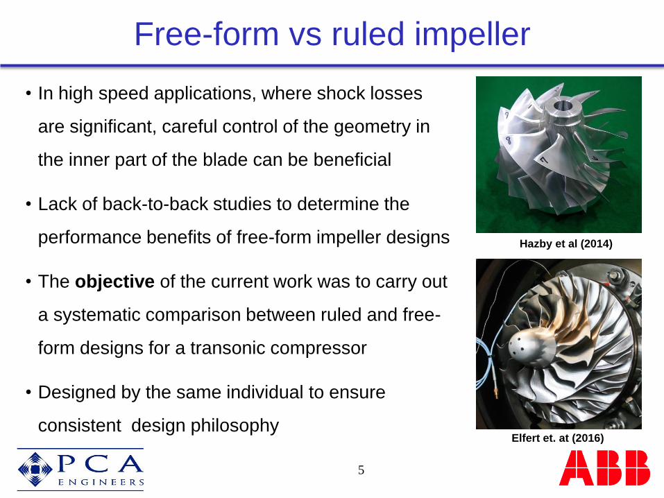
• In high speed applications, where shock losses
are significant, careful control of the geometry in
the inner part of the blade can be beneficial
• Lack of back-to-back studies to determine the
performance benefits of free-form impeller designs
• The objective of the current work was to carry out
a systematic comparison between ruled and free-
form designs for a transonic compressor
• Designed by the same individual to ensure
consistent design philosophy
5
Hazby et al (2014)
Elfert et. at (2016)

Outline of this talk
6
• Background and objectives
• Numerical procedure
• Impeller designs
• Datum impeller
• Free-form impellers
• Test results
• Part speed operation
• Conclusions

Numerical procedure
7
• Unstructured mesh with 500k
nodes and 10 prism layers
inside the volute
• k-ε Turbulence model with
scalable wall functions
• Impeller blades were designed in ANSYS Bladegen and checked for
mechanical integrity using ANSYS Mechanical
• ANSYS CFX was used for single passage steady state calculations
• Structured mesh (ANSYS Turbogrid) for impeller and diffuser with 500k
and 200k nodes, respectively

Outline of this talk
8
• Background and objectives
• Numerical procedure
• Impeller designs
• Datum impeller
• Free-form impellers
• Test results
• Part speed operation
• Conclusions

• Ruled design, using straight line generators
• A high pressure ratio impeller for Marine Turbocharger applications
• Inducer tip relative Mach number of 1.4 at the design point
Datum impeller
9
• Vaned diffuser
• High efficiency levels, representative of
the state-of-the-art performance
• Suitable to be used as a datum

• 9+9 vanes and 17° backsweep angle
• LE is swept backward for mechanical reasons
• Independent splitter design
• Low curvature in the uncovered part of the passage at
the tip
Datum impeller
10
• The tip section is not fully started at the
design condition with a bow shock
standing upstream of the main blade
leading edge
Contours of relative Mach number at 90% span

• Forward LE sweep in the upper span
• Increased meridional chord at the tip
• Similar design at TE (slightly higher work)
• Forward sweep of the LE generally:
• Moves the shock further downstream and
reduces the loading at the tip
• Reduces 1F frequency. It may need thicker
blade profiles at lower part
Forward swept impeller
11
Datum LE

• Blade profiles at hub and shroud are the same as
the forward swept impeller
• Increased meridional chord at 50% of the span
• 12% higher 1F frequency compare to the Forward
swept impeller
Barreled forward swept impeller
12
Datum LE

• All three blades have similar throat width distribution in the upper part of
the span
• Swept impellers have smaller throat area near the hub
Throat width distribution
13
throat width

Contours of Mrel and Entropy at 95% span
14
Datum Forward swept Barrelled forward swept
• Swallowed shock with reduced losses at the tip of the swept impellers
at design condition

Contours of static pressure and flow vectors near SS
15
Datum Forward swept Barrelled forward swept
• Weaker shock and reduced radial migration of the boundary layer flow in
the inner part of the barrelled forward swept impeller

Impeller performance
16
• No significant difference between the
performance of the swept impellers
• Swept impellers showed about 1%
higher total-to-total efficiency compared
with the datum impeller
• No significant impact of the LE sweep
on the operating range at the design
speed

Diffuser performance
17
• Inducer design had relatively small effect on the flow at the impeller outlet
• Similar diffuser pressure recoveries
Rotation
Datum
Forward swept
Barrelled forward swept

Further studies
18
• Application of the LE sweep changes :
• The length of the meridional chord at the tip
• The distribution of the inlet angle and throat area along the span
• The meridional profile of the LE
• An attempt has been made to study these effects in isolation

Further studies
19
• Ruled Extended chord impeller
• The tip section is the same as the
swept impeller
• The hub section is moved forward
• Free-form Unswept impeller
• The throat width and inlet angle
distributions are the same as the
Barrelled forward swept impeller
Extended chord
Unswept

Further studies
20
• Ruled Barrelled forward swept impeller
• Same tip profile as the free-form
version
• At the hub, blade thickness was
adjusted to achieve the same flow
capacity
• 4% lower 1F frequency and 57%
higher hub stress than the free-form
version
Barrelled forward swept

Contours of Mrel at 95% span
21
• Small effect of the chord length on the tip flow field
Extended chord Unswept Ruled barrelled swept
Datum Barrelled swept
• Geometry in the inner part of the
blade affects the flow at the tip
• LE sweep was less effective in
the ruled impeller
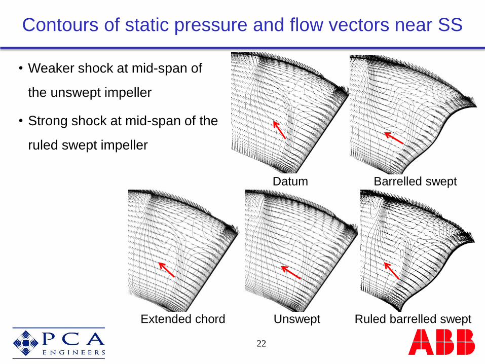
Contours of static pressure and flow vectors near SS
22
• Weaker shock at mid-span of
the unswept impeller
• Strong shock at mid-span of the
ruled swept impeller
Extended chord Unswept Ruled barrelled swept
Datum Barrelled swept

Impeller performance
23
• Unswept impeller showed 0.5%
higher efficiency than the datum
ruled design
• Relatively smaller effect of the
chord length and LE sweep when
applied to a ruled design
• Leading edge sweep should be
viewed as a design parameter
whose effects depend on other
geometrical parameters

Outline of this talk
24
• Background and objectives
• Numerical procedure
• Impeller designs
• Datum impeller
• Free-form impellers
• Test results
• Part speed operation
• Conclusions
Tested impellers
25
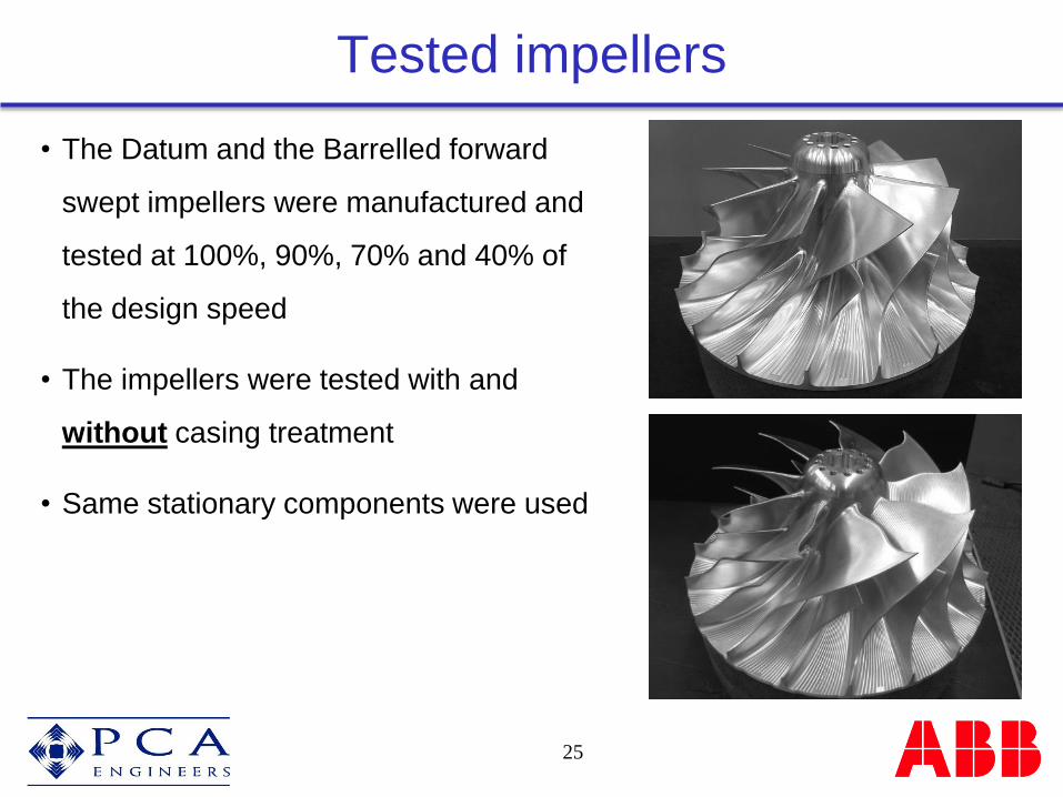
• The Datum and the Barrelled forward
swept impellers were manufactured and
tested at 100%, 90%, 70% and 40% of
the design speed
• The impellers were tested with and
without casing treatment
• Same stationary components were used

Measured performances
26
• Stage with the swept impeller shows:
• 0.5% higher efficiency and same
range at 100%speed
• 1.2% higher efficiency and 5.2%
wider range at 90% speed
• 1.6% higher efficiency but 17%
narrower range 70% speed
• 0.9% higher efficiency and the
same range at 40% speed

CFD vs. Measured performances
27
• Calculations suggest 1% improvement for swept impeller at design speed
• Trend is captured well especially at part speed
Experiments CFD

Outline of this talk
28
• Background and objectives
• Numerical procedure
• Impeller designs
• Datum impeller
• Free-form impellers
• Test results
• Part speed operation
• Conclusions

Impeller only performance
29
• Diffuser is matched to the impeller at the design speed
• At part speed, the impeller is forced (by diffuser choking) to operate on
the left hand side of its peak efficiency

90% of the design speed
30
• Similar flow fields at the tip
• Reduced loading and weaker shock at
the tip of the swept impeller results in
higher efficiency levels
Datum impeller
Barrelled forward swept impeller
P2
P1
P2 P1

70% of the design speed
31
• Datum impeller: Conventional inlet recirculation at the tip
• Swept impeller: Separation from 50%-80% span near LE at P1
Large separation in the upper part of
the span as the mass flow is
reduced
P2
P1 Datum impeller
Barrelled forward swept impeller
P2 P1

40% of the design speed
32
• Conventional inlet recirculation at the tip of the both datum and swept
impellers
• No significant difference in performance
of the impellers
Datum impeller
Barrelled forward swept impeller
P2 P1
P2
P1

Conclusions
33
• A barrelled forward sweep of the leading edge, offered better
mechanical properties while maintaining the performance benefits of the
forward swept impeller
• The observed performance improvements are combination effects of LE
sweep and other geometrical parameters such as angle and throat area
distributions
• The swept impeller showed 0.5% to 1.6% higher efficiency levels
compared with the datum impeller depending on the operating speed