free-space optical link with low alignment sensitivity using the … · 2005-09-23 · by free...
TRANSCRIPT

Free-Space Optical Link with LowAlignment Sensitivity using the 1553
Protocol
W. S. Rabinovich, R. Mahon, Peter G. Goetz, L. Swingen, T.Meehan, D. S. Katzer, S. Binari, G. C. Gilbreath
US Naval Research LaboratoryWashington, DC 20375
J. Rende, E. Waluschka, A, PhanNASA Goddard Space Flight Center
Greenbelt, MD
1. Project Goals
Data transfer on-board a spacecraft is typically done usingwiring harnesses (where the wires may be copper forelectrical signals or fiber optic for optical signals) using aserial protocol such as 1553 or 1773. This approach hasseveral limitations. The wiring harnesses themselves areundesirable because of their mass and large moment ofinertia. Also having an astronaut repair or add newconnections once the spacecraft has been launched is quitedifficult. The nature of the serial bus is also limiting becauseonly one instrument can talk at a time limiting the aggregatedata rate of the network.The object of the Cat's Eye Modulating Retro-reflectorprogram is to develop the components for a new type ofspacecraft data network that utilizes free space optical datatransfer. This free space optical network will allow theelimination of long wiring harnesses, enable point-to-pointdata connections, allow new data nodes to be added to aspacecraft after launch with relative ease, be immune to RFinterference and allow data networks to easily extend outsideof the spacecraft or to parts of distributed spacecrafts. Inaddition the network will not have the very accuratealignment tolerances between nodes that is generally requiredby free space optics.
2. Background
2.1 Optical data transfer
Optical data communications using fiber optic connections israpidly becoming the standard method of data transfer,particularly when high bandwidth or RF interference issuesare important. Free space optical data transfer is alsocommonly used for short range, relatively low data rate links
between portable or handheld computers (IRDA) or, evenmore commonly, in a variety of remote controls for consumerdevices such as televisions or cameras. These broad-beamfree space interconnects generally link a single transmitterdevice to a single receiver device. In fact such aninterconnect can in principle allow a device to communicatewith several receiver nodes at once but not in a point-to-pointfashion. As shown below in Figure 1, in such a link thetransmitter sends the same signal to all nodes.Broad beam free space interconnects generally have moderatedata rates (less than 10 Mbps) because they use low poweremitters such as LEDs and because they spread their lightover such a large area that there are insufficient receivedphotons to support a high-speed link. Nonetheless such linksare attractive because they have low sensitivity to alignment.Indeed the simplest replacement for a 1553 bus on aspacecraft would be a set of broad beam free space links.
Figure 1 A broad beam free space optical interconnect
There are other applications in which high single channeldata rate, point-to-point links are desired. These include datatransfer between boards or even chips in a computer or fromhigh data rate imaging sensors. For these applications anotherfree space optical approach has been investigated intensivelyover the past decade1. This approach uses combinations ofemitters, modulators and detectors arranged in planar arrayscombined with micro-optics. As shown below in Figure 2 insuch a system, a transmitter in one plane is tightly imagedonto a receiver in a second plane. Two forms of transmittersare used. In one case a single laser is split into multiplebeams each of which is modulated by a pixel in a modulatorarray. Alternatively the transmitter may be a small laser suchas a VCSEL, which is directly modulated. These systemshave the advantage of very high single channel data rates(hundreds of Mbps) because they are very efficient in theiruse of light. They are also true point-to-point systems with nocross talk between nodes. The net result is a potential ofextremely high aggregate date rates exceeding terabits persecond. The downside of this approach is extremely precise
Emitter Photodetector
positional and angular alignment requirements of about 100microns and 100 microradians (for a 1 meter long link)respectively. Such requirements are difficult to manufactureand maintain in equipment destined for use in the controlledenvironment of a terrestrial computer room and may beimpossible to meet for spacecraft systems that must survivelaunch and work without maintenance for years2.
Figure 2: A micro-optical free space interconnect
2.2 Modulating retro-reflectors
An alternative to the broad-beam or micro-optical free spaceoptical interconnects is a new approach based on cat's eyemodulating retro-reflectors (CEMRR). A modulating retro-reflector combines a passive optical retro-reflector with anactive electro-optic shutter. Because retro-reflection isalignment insensitive, these kinds of links can combine someof the features of broad-beam and micro-optic links.
2.3 Multiple Quantum Well Modulators
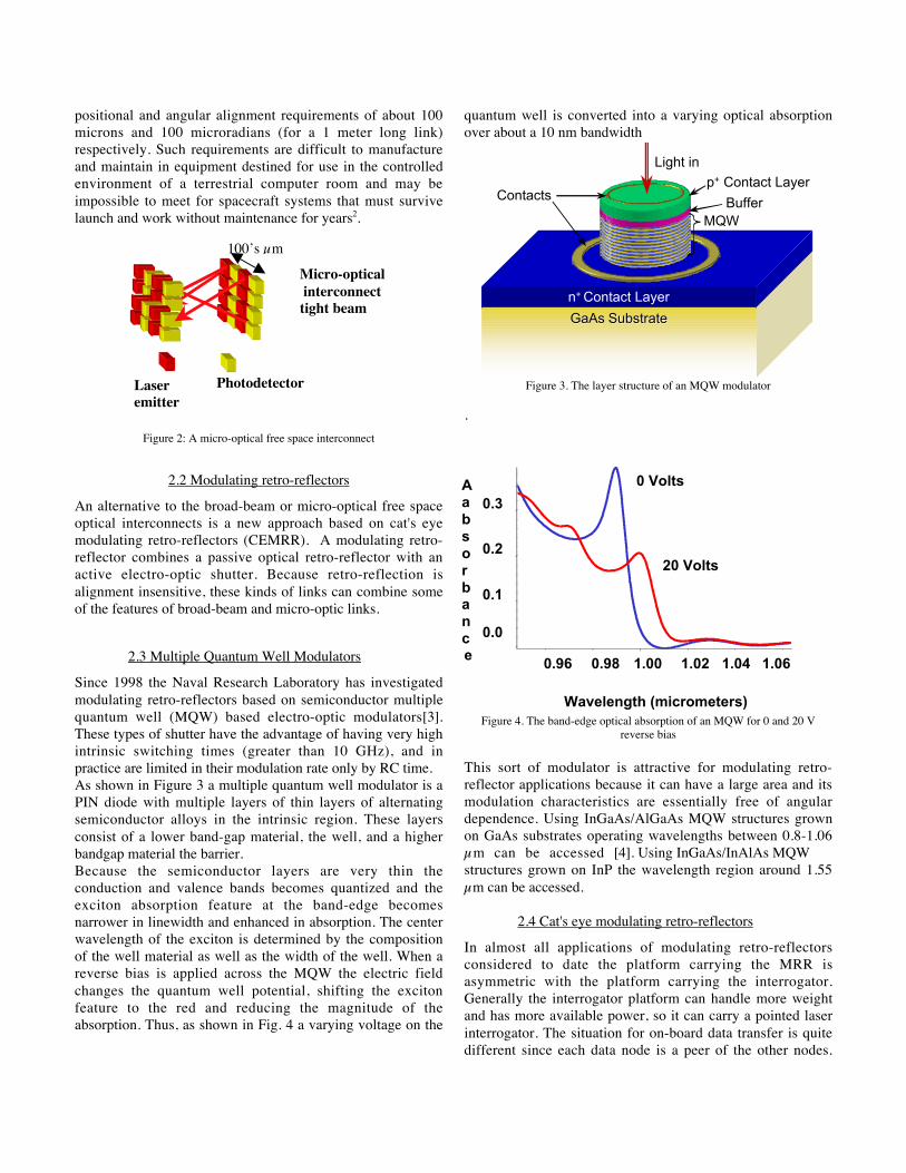
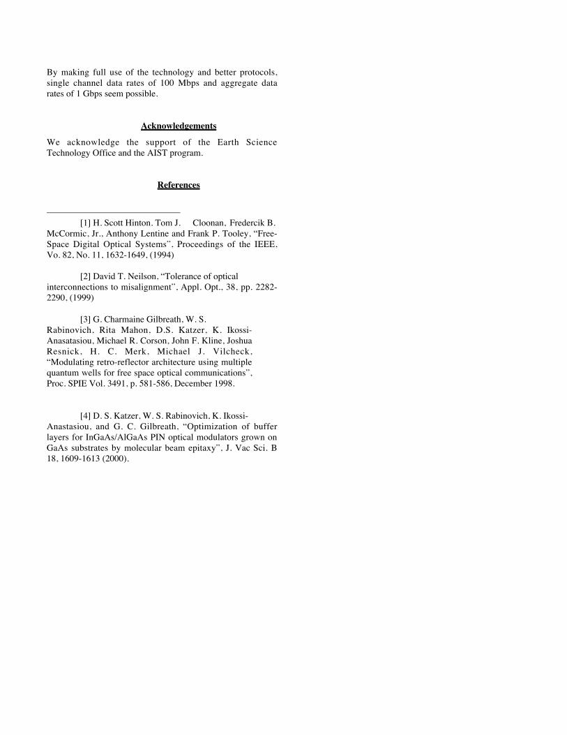
Since 1998 the Naval Research Laboratory has investigatedmodulating retro-reflectors based on semiconductor multiplequantum well (MQW) based electro-optic modulators[3].These types of shutter have the advantage of having very highintrinsic switching times (greater than 10 GHz), and inpractice are limited in their modulation rate only by RC time.As shown in Figure 3 a multiple quantum well modulator is aPIN diode with multiple layers of thin layers of alternatingsemiconductor alloys in the intrinsic region. These layersconsist of a lower band-gap material, the well, and a higherbandgap material the barrier.Because the semiconductor layers are very thin theconduction and valence bands becomes quantized and theexciton absorption feature at the band-edge becomesnarrower in linewidth and enhanced in absorption. The centerwavelength of the exciton is determined by the compositionof the well material as well as the width of the well. When areverse bias is applied across the MQW the electric fieldchanges the quantum well potential, shifting the excitonfeature to the red and reducing the magnitude of theabsorption. Thus, as shown in Fig. 4 a varying voltage on the
quantum well is converted into a varying optical absorptionover about a 10 nm bandwidth
GaAsGaAs SubstrateSubstrate
n+ Contact Layer
MQW
Contactsp+
Light in
p+ Contact Layer
Buffer
Figure 3. The layer structure of an MQW modulator
.
Figure 4. The band-edge optical absorption of an MQW for 0 and 20 Vreverse bias
This sort of modulator is attractive for modulating retro-reflector applications because it can have a large area and itsmodulation characteristics are essentially free of angulardependence. Using InGaAs/AlGaAs MQW structures grownon GaAs substrates operating wavelengths between 0.8-1.06µm can be accessed [4]. Using InGaAs/InAlAs MQWstructures grown on InP the wavelength region around 1.55µm can be accessed.
2.4 Cat's eye modulating retro-reflectors
In almost all applications of modulating retro-reflectorsconsidered to date the platform carrying the MRR isasymmetric with the platform carrying the interrogator.Generally the interrogator platform can handle more weightand has more available power, so it can carry a pointed laserinterrogator. The situation for on-board data transfer is quitedifferent since each data node is a peer of the other nodes.
Laseremitter
Photodetector
100’s µm
Micro-optical interconnecttight beam
0.0
0.1
0.2
0.3Aabsorbance
1.00
Wavelength (micrometers)
0.98 0.96 1.02 1.04 1.06
0 Volts
20 Volts

None of the nodes can use active pointing to maintain a linkin the presence of environmental perturbations. The challengethen is to make use of the retro-reflection characteristics of anMRR to relieve pointing requirements on both ends of thelink. We can do this by combining the MRR concept with thebroad beam free space interconnect described earlier. Such asystem allows point-to-point interconnects because noinformation is carried on the broad angle beam, only on thenarrow divergence retro-reflected beams; thus there is nocross-talk.To implement such a system we examined the use of adifferent form of MRR using a cat's eye retro-reflector. Thereis no one form for a cat's eye retro-reflector, but theygenerally combine lenses and mirrors and incorporate anoptical focus. A spherical cat's eye is shown below in Figure5.
Figure 5: A spherical cat's eye retro-reflector.
We can use the fact that a cat's eye retro-reflector has anoptical focus whose position varies based on the incidenceangle of light upon the cat's eye to channelize the return frommultiple nodes and allow point to point links. We havedesigned an alternative form of cat's eye retro-reflector thatuses a telecentric lens pair, a flat mirror and a MQWmodulator/receiver array inserted into the optical system infront of the mirror. This cat's eye modulating retro-reflector(CEMRR) node also has an emitter, a fiber coupled laserdiode reflected from a dot coupler placed in front of the cat'seye aperture. A diagram of a CEMRR node is shown belowin Figure 6.
Figure 6: A cat's eye modulating retro-reflector transmitter/receiver node
A set of CEMRR nodes can exchange data in a point-to-pointfashion by interrogating each other with broad cw laserbeams and receiving narrow divergence retro-reflected signalcontaining data streams. Below, in Figure 7, a typical set ofCEMRR nodes is shown. The node on the right will act as aninterrogator, while the nodes on the left will act astransmitters.
Figure 7: A set of cat's eye modulating retro-reflector nodes
Figure 8: A cat's eye interrogator node paints two cat's eye transmitter nodes
In operation, as shown in Figure 8, the interrogator nodeemits a broad cw laser beam that paints both of thetransmitter nodes. This beam carries no information so thefact that it intercepts two nodes causes no cross talk. Its broadangular divergence and large footprint ensures that theinterrogation beam has little positional or angular sensitivity.As shown in Figure 9, the portion of the interrogation beamthat intercepts each interrogator node is focused by the lenses
Cat’s eyelenses Pixellated
MQWMirror
Fiber coupledlaser diode
Dotcoupler
10 cm

and passes through a pixel in the MQW array. The particularpixel that the light passes through depends on the relativespatial positions of the interrogator and transmitter. In aproperly designed CEMRR system each pair of nodes willhave a unique pixel associated with it. This is what allowspoint-to-point links.
Figure 9: The beam path upon interrogation in the transmitter nodes of aCEMRR system
The light passes through the transmitter node MQW pixeltwice (once on entering and once on reflection). This pixelhas a modulated voltage placed upon it. This modulates thecw light with the signal, which the transmitter node wishes tosend back to the interrogator. As shown in Figure 10 this lightthen retro-reflects in a narrow divergence beam back to theinterrogator.
Figure 10: The transmitter nodes retro-reflect their data back to theinterrogator node.
Figure 11: The retro-reflected signals are detected by the interrogator.
Finally the retro-reflected beams intercept the lenses of theinterrogator node where they focus onto the interrogator'sMQW array, again onto a particular pixel determined by therelative positions of the interrogator node and the transmitternode. In this case however, we bias the MQW with a constantvoltage and detect the photocurrent produced by the retro-reflected beam. Because an MQW is a PIN diode it can act asa photodetector. As shown in Figure 11 the retro-reflectedsignals from each transmitter focus onto different interrogatorMQW pixel.A system of CEMRRs has a variety of sensitivities to angularor positional misalignment. If the interrogator position shiftsthe broad interrogating beam will shift with it, but as long asthe interrogator shift is less than the footprint of theinterrogating beam the link will be maintained. Similarly ifthe position of either of the transmitters shifts by less than theinterrogating footprint the link will be maintained. If theangle of the interrogator shifts the position of theinterrogating beam will shift, but if this angular shift issmaller than the angular width of the interrogating beam thenthe transmitter nodes will still be painted with theinterrogating beam. If the angle of a transmitter node shifts itwill have no effect on the link, because of the retro-reflection,for shifts within the field of view of the cat's eye retro-reflector (typically about 30 degrees).A more subtle alignment sensitivity occurs upon retro-reflection if the positions of any of the nodes shift. For shiftssmaller than the interrogator footprint retro-reflection willstill occur but the focal positions on the MQW arrays in boththe interrogator and the transmitters will shift. Because of thedemagnification of the cat's eye lenses the focal plane shift ismuch smaller than the physical shift of the nodes. This shiftcan be handled in two possible ways. First, if the pixels aresufficiently large then these positional shifts will not movethe focal spots off the proper pixel. For a typical system, a1mm pixel would allow for 5 cm node shift. An alternativeapproach is to overfill the MQW array with more pixels thannodes. Then if a shift occurs pixels can be reassigned to

different node pairs. An advantage of the second approach isthe possibility of adding more nodes later on. This opens upthe possibility of networks that can automatically add newphysical point-to-point connections as new nodes are added.The net result of the CEMRR system is one which combinessome of the features of both broad beam and micro-opticalfree space interconnects. The system has the low alignmentsensitivity of the broad beam system but has the point-to-point connectivity of the micro-optical system. It is lessefficient in its handling of light than the micro-optical systembut more efficient than the broad beam system (because allthe nodes that fall within the footprint of the interrogatorbeam have their own data channel)
3. A 1553 Cat’s Eye Data Link
To demonstrate the utility of a cat’s eye modulating retro-reflector we have been developing a free space optical 1553bus using CEMRR nodes. The 1553 protocol is not optimalfor using CEMRRs but it is ubiquitous on spacecraft and so isa good first step towards more flexible architectures.A cat’s eye modulating retro-reflector system requires anintegrated set of optical, electronic and photonic components.The optical system must retro-reflect light (though diffractionlimited beam quality and accuracy is not needed for short-range links). It must also allow for the insertion of an MQWmodulator/receiver array into the optical chain. The MQWdevice must balance the requirements of optical modulationwith photoresponse. It must also be robust enough to survivelaunch and operate in a spacecraft environment. The interfaceto the 1553 bus presents a set of challenges. The 1553 signalmust be converted to the appropriate driving voltage for theMQW when the MQW is used as a modulator. When theMQW is used as a receiver a DC bias must be put on thedevice and the photocurrent must be amplified up to the pointwhere it can be reinserted into the electrical 1553 bus. Thelogic and components must encompass these needs as well asat least simulate a peer-to-peer bus. In the subsections belowwe will describe our progress to date on these goals.
3.1. Optical Design
Unlike a typical cat's eye retro-reflector the optics in theCEMRR nodes must accommodate a planar MQW array. Weapproached this problem by using a 1 cm diameter telecentriclens with a planar, reflective MQW array in the focal plane.This arrangement retro-reflects light over a 30-degree field ofview with a retro-reflected beam divergence of 1 milliradian(approximately 4 times the diffraction limit). The focal spot atthe modulator plane is 140 microns in diameter.In addition to the cat’s eye optic the CEMRR node mustincorporate a laser to emit the broad interrogation beam. It isnot necessary for each node to have its own laser. The lightfrom a single laser diode can be divided and distributed usingoptical fiber to a number of closely spaced nodes acting as a
sort of optical power supply. Because the interrogation beamwill be precisely retro-reflected the interrogation beam shouldbe centered on the cat’s eye optic. We achieved this by usinga laser diode coupled to a single mode fiber. The fiber wascoupled to a lens, which was adjusted to diverge the beam toa diameter of 15 cm at a distance of 3 meters from the node.A glass window with a 1 mm diameter gold dot in its centerwas mounted directly in front of the cat’s eye optic and thelight from the laser diode was reflected off the dot andtowards the other nodes. Because the fiber was quite close tothe gold dot almost all of the light from the laser is coupledout into the interrogation beam. Upon retro-reflection thereturn beam is approximately 1.5 cm in diameter so that the1mm dot obscures only a small part of the light entering thecat’s eye lens. Figure 12 below shows the CEMRR node
Dot coupler
Cat’s eyeoptic
Focal planeMQW/Circuitry
Fiber coupledLaser diode
Figure 12: A cat’s eye modulating retro-reflector node
3.2 MQW Modulator/Receiver
A multiple quantum well structure consists of multiple thinlayers of semiconductor alloys. The alloy with the lowerenergy band-gap is called the well and the alloy with thehigher energy-band-gap is called the barrier. The alloycomposition and width of the well material determine theoperating wavelength of the modulator.The MQW devices for the CEMRR nodes must act as bothoptical modulators and photodetectors. This places someadditional restrictions on the design of the MQW layers. Inparticular to maintain good photodetector responsivity thebarriers must not be too thick, but if the barriers are too thinthe optical modulation contrast will be low. We designed aMQW structures using a self-consistent transfer matrix code.The MQW was designed for operation at 980 nm and weregrown via molecular beam epitaxy at NRL.We chose 980 nm as the operating wavelength. 980 nm laserdiodes are used to pump 1550 nm Erbium doped opticalamplifiers used by the telecommunications industry. The useof 980 nm diode lasers allows us to leverage the high

investment by industry in making these lasers powerful andreliable.A photolithography mask was created and a set of 1mmMQW test structures was produced by metallization and wetchemical etching.
We evaluated the resulting device's DCphotoresponse by placing the structure under a DC reversebias illuminating it with a calibrated, tunable, laser diode andmeasuring the current. A dark current measurement was alsotaken. The subtraction of the two curves gives the DCphotoresponse shown below in Figure 13.
Figure 13: DC Photoresponse of 980 nm MQW structure
The responsivity, shown by the green curve, becomesrelatively flat by about 8 V reverse bias at about 0.3 A/W. Atbiases above about 20 V the responsivity climbs again,perhaps due to avalanche gain.The modulation contrast of the MQW was measured using asimilar set-up to that used for measuring the photoresponse.In this case the light passing through the MQW was focusedonto a silicon photodetector. A modulated bias was placedupon the structure and the resultant modulated optical signalwas measured. The extinction ratio of the modulator was 0.6.Higher extinction ratios can be achieved with MQWmodulators, but at the cost of photoresponse.
3.3 MQW Array
The geometry of the pixellated MQW array is determined bythe optics of the cat’s eye lens and the location of the othernodes in the system. The focal spot moves 1mm for a 2.5°change in incident angle upon the cat’s eye. For a link lengthof 3 meters and a node separation of 10 cm the pixelseparation must be 800 microns. A 2 x 2 pixelphotolithography mask, shown below in Figure 14, was usedto process the MQW into 4 pixel devices. The backside of thewafer was coated with gold to act as a reflector.
Figure 14: Cat’s eye array photolithography mask
3.4 MQW Driver/Preamplifier Electronics
To operate as a transmit node in a1553 network driverelectronics must take the incoming 1553 signal and convert itto produce the necessary modulation drive. When operatingas a receiver the electronics must amplify the photocurrentsufficiently to feed back into the 1553 network. We achievedthis by reverse biasing the MQW at a constant 8.5V whenoperating in receive mode and then coupling in a ±8.5Vdigital signal when in transmit mode. When operating as areceiver the photocurrent passes into a transimpedenceamplifier (TIA) designed to boost the signal to approximately30 mV.
Figure 15: Block diagram for cat’s eye focal plane electronics
In addition we found it necessary to include a CMOS analogconnected to ground between the MQW and the preamplifier.This switch is operated by a TTL control line that closes theswitch when in transmit mode. This is necessary because thevery large currents (compared to the photocurrent) used tomodulate the MQW saturate the preamplifier preventing it
Responsivity of M13 at 968 nm, 21.6 uW
0.E+00
1.E-05
2.E-05
3.E-05
4.E-05
5.E-05
6.E-05
7.E-05
0 5 10 15 20 25
Reverse Bias (V)
Cu
rren
t (A
)
illuminated
dark current
difference
BiasT
TIAOPA655
MQWDriverLM7372
CMOSAnalogSwitch
1553DeviceSigIn
1553DeviceSigOut
Volt.reg.
+15 VGND
-15V
-8.5 V
8.5 V
5 V 5 V
1553 opticalSignal In/Out
TTL in

from holding ground on the MQW side. The CMOS switchallows us to directly shunt to ground. A block diagram of thecircuit is shown below in Figure 15. In operation we foundthat the device switches from transmit to receive mode inapproximately 1.5 microseconds.
3.5 Cat's eye link budget
Using 2 CEMRR nodes we measured a 2-meter cat’s eye linkusing a 10 cm spot size at the interrogated node and 6 mW ofoptical transmit power. The SNR of the received signal was50, sufficient for a raw bit error rate of 10-9. The budget forthis link is shown below
Source 8 dBmGeometric loss -20 dBTransmitter cat’s eye optical loss -4 dBMQW loss -5 dBMQW modulation contrast -4 dBGeometric loss (transmitter to interrogator) -3 dBInterrogator cat’s eye optical loss -2 dB
Total -30 dBmReceiver sensitivity -30 dBm
3.5 1553 Logic and InterfaceA 2-node 1553 bus was set up with a 3-meter free space linklength. In this bus one CEMRR node acted as the master andthe other as the remote terminal. Signals passes normally andthe free space optical portion of the bus was transparent to theinstruments hooked to it. The physical arrangement of thenodes is shown below in Figure 16 and a typical trace fromthe data stream in Figure 17.
Figure 16: Laboratory set-up for the free space 1553 bus.
In operation the CEMRR nodes could be moved severalcentimeters and twisted by several degrees without disturbingthe link. Thus these sorts of free-space links should be quite
robust against vibrations misalignment. They are alsorelatively easy to set-up since alignment tolerances are loose.
Figure 17: 1553 data trace transmitted over the free space optical bus
4 Conclusions
Free space optical data transmission offers many advantagesfor data networks on-board spacecraft. The CEMRRapproach essentially trades efficient use of laser power forreduced alignment sensitivity. Since lasers diodes areexcellent converters of electrical power into light (generallyexceeding 50% efficiency) this is often a good bargain.We implemented a 1553 bus using CEMRR nodes becausethis protocol is the most widely used onboard spacecraft. It ishowever a poor choice of protocol for making the most ofwhat the cat’s eye approach has to offer. This is because theCEMRR nodes are really a self-configuring point-to-pointnetwork rather than a serial network. For our currenthardware each node is capable of simultaneously supporting a1 Mbps link to every other node. Thus for example, a 10-node system could support an aggregate data rate of 100Mbps. However, since the 1553 protocol is a serial one Weare limited to a total aggregate data rate equal to our singlechannel rate of 1 Mbps. In the future we hope to exploremore powerful protocols that will allow fuller exploitation ofthe technology.It is also important to point out that the 1 Mbps singlechannel data rate of the current system is by no means thelimit. The maximum modulation bandwidth of the MQWdevices at the current 800-micron pixel size is approximately50 MHz, and higher rates would be possible with smallerpixels. Faster links would of course require more opticalpower of higher detector sensitivity. Both are possible. Thecurrent 1 Mbps 3 meter link can be closed using 15 mW oflaser light. But high reliability 300 mW 980 nm laser diodesare now available and more power can be expected in thefuture. In addition it maybe possible to improved thephotoresponse of the MQW devices by exploiting internalavalanche gain or coherent processes.
CEMRR
By making full use of the technology and better protocols,single channel data rates of 100 Mbps and aggregate datarates of 1 Gbps seem possible.
Acknowledgements
We acknowledge the support of the Earth ScienceTechnology Office and the AIST program.
References
[1] H. Scott Hinton. Tom J. Cloonan, Fredercik B.
McCormic, Jr., Anthony Lentine and Frank P. Tooley, “Free-Space Digital Optical Systems”, Proceedings of the IEEE,Vo. 82, No. 11, 1632-1649, (1994)
[2] David T. Neilson, “Tolerance of opticalinterconnections to misalignment”, Appl. Opt., 38, pp. 2282-2290, (1999)
[3] G. Charmaine Gilbreath, W. S.Rabinovich, Rita Mahon, D.S. Katzer, K. Ikossi-Anasatasiou, Michael R. Corson, John F. Kline, JoshuaResnick, H. C. Merk, Michael J. Vilcheck,“Modulating retro-reflector architecture using multiplequantum wells for free space optical communications”,Proc. SPIE Vol. 3491, p. 581-586, December 1998.
[4] D. S. Katzer, W. S. Rabinovich, K. Ikossi-Anastasiou, and G. C. Gilbreath, “Optimization of bufferlayers for InGaAs/AlGaAs PIN optical modulators grown onGaAs substrates by molecular beam epitaxy”, J. Vac Sci. B18, 1609-1613 (2000).