frequency-agile uhf wireless · pdf filethis lightning flash with arrowhead symbol within an...
TRANSCRIPT

OWNER'S MANUAL
FREQUENCY-AGILE UHF WIRELESS SYSTEM

Copyright 2015 - Samson Technologies V1.3
Samson Technologies 45 Gilpin Avenue Hauppauge, New York 11788-8816 Phone: 1-800-3-SAMSON (1-800-372-6766) Fax: 631-784-2201 www.samsontech.com
3Concert 99 Wireless System
Important Safety Information1. Read these instructions.2. Keep these instructions.3. Heed all warnings.4. Follow all instructions.5. Do not use this apparatus near water.6. Clean only with dry cloth.7. Do not block any ventilation openings. Install in accordance with the manufacturer’s instruc-
tions.8. Do not install near any heat sources such as radiators, heat registers, stoves, or other apparatus
(including amplifiers) that produce heat.9. Do not defeat the safety purpose of the polarized or grounding type plug. A polarized plug has
two blades with one wider than the other. A grounding type plug has two blades and a third grounding prong. The wide blade or the third prong are provided for your safety. If the provided plug does not fit into your outlet, consult an electrician for replacement of the obsolete outlet.
10. Protect the power cord from being walked on or pinched particularly at the plugs, convenience receptacles, and at the point where they exit from the apparatus.
11. Only use attachments/accessories specified by the manufacturer.12. Use only with the cart, stand, tripod, bracket, or table specified by the manufac-
turer, or sold with the apparatus. When a cart is used, use caution when moving the cart/apparatus combination to avoid injury from tip-over.
13. Unplug the apparatus during lightening storms, or when unused for long periods of time. 14. Refer all servicing to qualified personnel. Service is required when the apparatus has been
damaged in any way, such as power supply cord or plug is damaged, liquid has been spilled or objects have fallen into the apparatus has been exposed to rain or moisture, does not operate normally, or has been dropped.
15. This appliance shall not be exposed to dripping or splashing water and that no object filled with liquid such as vases shall be placed on the apparatus.
16. Caution-to prevent electrical shock, match wide blade plug wide slot fully insert.17. Please keep a good ventilation environment around the entire unit.18. The direct plug-in adapter is used as disconnect device, the disconnect device shall remain
readily operable.19. Batteries (battery pack or batteries installed) shall not be exposed to excessive heat such as
sunshine, fire or the like.
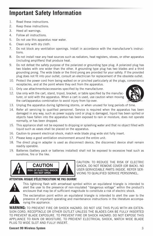
CAUTION: TO REDUCE THE RISK OF ELECTRIC SHOCK, DO NOT REMOVE COVER (OR BACK). NO USER-SERVICEABLE PARTS INSIDE. REFER SER-VICING TO QUALIFIED SERVICE PERSONNEL.
This lightning flash with arrowhead symbol within an equilateral triangle is intended to alert the user to the presence of non-insulated “dangerous voltage” within the product’s enclosure that may be of sufficient magnitude to constitute a risk of electric shock.
The exclamation point within an equilateral triangle is intended to alert the user to the presence of important operating and maintenance instructions in the literature accompa-nying the appliance.
ATTENTION: RISQUE D’ÉLECTROCUTION! NE PAS OUVRIR!
WARNING: TO PREVENT FIRE OR SHOCK HAZARD. DO NOT USE THIS PLUG WITH AN EXTEN-SION CORD, RECEPTACLE OR OTHER OUTLET UNLESS THE BLADES CAN BE FULLY INSERTED TO PREVENT BLADE EXPOSURE. TO PREVENT FIRE OR SHOCK HAZARD. DO NOT EXPOSE THIS APPLIANCE TO RAIN OR MOISTURE. TO PREVENT ELECTRICAL SHOCK, MATCH WIDE BLADE PLUG TO WIDE SLOT AND FULLY INSERT.

4
Important Safety Information
If you want to dispose this product, do not mix it with general household waste. There is a separate collection system for used electronic products in accordance with legislation that requires proper treatment, recovery and recycling.
Private household in the 28 member states of the EU, in Switzerland and Norway may return their used electronic products free of charge to designated collection facilities or to a retailer (if you purchase a similar new one).
For Countries not mentioned above, please contact your local authorities for a correct method of disposal.
By doing so you will ensure that your disposed product undergoes the necessary treatment, recovery and recycling and thus prevent potential negative effects on the environment and human health.
FCC Rules and Regulations
Samson wireless receivers are certified under FCC Rules part 15 and transmitters are certified under FCC Rules part 74.
Licensing of Samson equipment is the user’s responsibility and licensability depends on the user’s classification, application and frequency selected.
NOTE: This equipment has been tested and found to comply with the limits for a Class B digital device, pursuant to Part 15 of the FCC Rules. These limits are designed to provide reasonable protection against harmful interference in a residential installation. This equipment generates, uses and can radiate radio frequency energy and, if not installed and used in accordance with the instructions, may cause harmful interference to radio communications. However, there is no guarantee that interference will not occur in a particular installation. If this equipment does cause harmful interference to radio or television reception, which can be determined by turning the equipment off and on, the user is encouraged to try to correct the interference by one or more of the following measures:
• Reorient or relocate the receiving antenna.
• Increase the separation between the equipment and receiver.
• Connect the equipment into an outlet on a circuit different from that to which the receiver is connected.
• Consult the dealer or an experienced Radio/TV technician for help.
WARNING: Changes or modifications not expressly approved by the party responsible for compliance could void the user’s authority to operate the equipment.
This device complies with RSS-210 of Industry & Science Canada. Operation is subject to the fol-lowing two conditions:
(1) this device may not cause harmful interference and
(2) this device must accept any interference received, including interference that may cause unde-sired operation.
This equipment is intended for use in wireless microphone applications.
Equipment is intended for sale in: AT, BE, CH, CY, CZ*, DK, EE, FI*, FR*, DE*, GR*, HU, IE, IS, IT, LV, LT*, LU, MT*, NL, NO*, PL* PT, RO, SK, SI, ES, SE, UK
*Subject to license. Please contact your national frequency authority for information on avail-able legal use in your area. Any changes or modifications not expressly approved by Samson Technologies Corp. could void your authority to operate the equipment.
5Concert 99 Wireless System
Congratulations on purchasing the Samson Concert 99 wireless system. The Concert 99 is the ideal solution for the active performer who needs a reliable, great sounding system for wireless applica-tions. Featuring an large backlit LCD display, simple operation with auto-scan channel selection, and infrared set for syncing the transmitter and receiver channel, the Concert 99 is simple and easy to set up and operate. The Concert 99 system ensures clear, interruption-free performance by utilizing a True RF Diversity design with a pilot tone-key and auto-mute function. This configuration provides maximum operating distance along with eliminating any background noise when the transmitter is out of range or powered off.
The Concert 99 comes in four configurations. The vocal handheld system includes the CH99 hand-held transmitter with Samson’s Q8 premium dynamic microphone capsule. The CB99 belt pack sys-tem can be configured with either the SE10 earset microphone, LM10 lavalier microphone, or a ¼" instrument cable. The Concert 99 includes a standard 19" rackmount kit for permanent installations or transporting in a mobile rack.
In these pages, you’ll find a detailed description of the features of the Concert 99 wireless system, as well as step-by-step instructions for its setup and use. If your wireless system was purchased in the United States, you’ll also find a registration card enclosed—don’t forget to follow the instructions so that you can receive online technical support and so that we can send you updated information about this and other Samson products in the future. Also, be sure to check out our website www.samsontech.com for complete information about our full product line.
We recommend you keep the following records for reference, as well as a copy of your sales receipt:
Receiver Serial number: _________________________________________
Transmitter Serial number: ______________________________________
Date of purchase: ______________________________________________
With proper care and maintenance, your Concert 99 wireless system will operate trouble-free for many years. Should your wireless system ever require servicing, a Return Authorization (RA) number must be obtained before shipping your unit to Samson. Without this number, the unit will not be accepted. Please call Samson at 1-800-3SAMSON (1-800-372-6766) for an RA number prior to shipping your unit. Please retain the original packing materials and, if possible, return the unit in its original carton. If your Concert 99 system was purchased outside of the United States, contact your local distributor for warranty details and service information.
Introduction
System Features• Professional wireless system for use in both live sound and sound contracting applications
• True RF Diversity technology maximizes active range (up to 300 feet) and reduces potential interference
• 80 available channels operating in the UHF band designed for maximum system compatibility in the same location without interference
• The CR99 receiver is a metal half-rack unit that can be used freestanding or can be mounted in any standard 19" rack using the included rack kit, making it easy to integrate into any traveling or fixed installation audio system
• Tone-key and auto-mute ensures clear, interruption-free performance allowing only the transmitter’s audio to pass through the receiver, and mutes the output if the transmitter is powered off or out of range.
• Up to 300-foot range (line-of-sight)
• Up to eight hours of battery life, using two standard AA batteries

6
A. Group - Displays the selected group
B. Channel - Displays the selected channel
C. Frequency - Indicates the operating frequency of the selected Group and Channel.
D. Antenna Indicator - Indicates the active antenna (A or B).
E. Transmitter Battery Level - Indicates the battery level of the transmitter.
F. Audio Meter - Indicates the strength of the incoming audio signal.
G. RF Signal Meter - Indicates the strength of the incoming radio signal.
Receiver Display
1. Antenna Jacks - The front BNC antenna jacks allow full rotation for optimum place-ment. In normal operation, both antennas should be placed in a vertical position.
2. VOLUME Control - This knob sets the level of the audio signal being output through both the balanced and unbalanced output jacks on the rear panel. Reference level is obtained when the knob is turned fully clockwise (to its “10” setting).
3. LCD Display - Displays transmitter and receiver settings.
4. GROUP Button - Press and release button to cycle through the available groups. Press and hold button to scan for available channels within the selected group.
5. CHANNEL Button - Press and release to cycle through available channels within a group. Press and hold button to enter IR Set which is used to set the operating channel of the transmitter.
6. POWER Button - Press and hold to turn the CR99 power on and off.
7. IR Transmitter - During “IR SET” an infrared light is used to set the transmitter channel.
CR99 Receiver - Front Callouts
1 2 3
4
5 6
7
1
A
D
F
G
E
B C

7Concert 99 Wireless System
1 12 3 4
Using the strain relief: Gather up a loop of wire and pass it through the strain relief, then pass the adapter plug through the loop in order to create a knot.
CR99 Receiver - Rear Callouts
1. Antenna Jacks - The rear BNC antenna jacks allow full rotation for optimum placement. In normal operation, both antennas should be placed in a vertical position.
2. DC Input - Connect the supplied power adapter here, using the strain relief as shown in the illustration below. WARNING: Do not substitute any other kind of power adapter. Doing so can cause severe damage to the CR99 and will void your warranty.
3. BALANCED OUTPUT - Use this electronically balanced low impedance (600 Ohm) XLR jack when connecting the CR99 to professional (+4dBu) audio equipment. Pin wiring is as follows: Pin 1 ground, Pin 2 high (hot), and Pin 3 low (cold).
4. UNBALANCED OUTPUT - Use this unbalanced high impedance (5K Ohm) ¼" jack when connecting the CR99 to consumer (-10dBV) audio equipment. Wiring is as follows: tip hot, sleeve ground.

8
CB99 Belt Pack Transmitter - Callouts1. Input Connector - Connect the input device via the
mini-XLR connector. The CB99 is supplied with either a lavalier, headset microphone or ¼" instru-ment cable.
2. Status Indicator - This LED displays the operation mode: GREEN Normal Operation
RED Mute
Flashing GREEN Low Battery
3. Power/Mute Switch - Press and hold to turn the unit on or off. Press and release to mute or unmute the transmitter.
4. Belt Clip - Use this clip to fasten the CB99 trans-mitter to a belt or guitar strap.
5. Battery Cover Release - Push in both sides and pull back to open the CB99 battery cover.
6. Antenna - This permanently attached transmitter antenna should be fully extended during normal operation.
7. Input GAIN Control - This control adjusts the trans-mitter input sensitivity to work with microphone and instruments inputs. For optimal performance, using the included screwdriver, set the input GAIN control to where you see the CR99 Audio Meter maximum indicator start to light under high levels, then turn down slowly until the maximum indicator stops lighting.
8. Battery Holder - Insert two standard AA (LR6) bat-teries here, being sure to observe the plus and minus polarity markings shown. Although recharge-able NiCad and NiMH batteries can be used, they do not supply adequate current for more than four hours. WARNING: Do not insert the batteries back-wards; doing so can cause severe damage to the CB99 and will void your warranty.
9. IR Lens - This window is used to capture the infra-red signal sent from the CR99 receiver d u r i n g the IR SET to channelize the transmitter.
10. Plastic Screwdriver - Designed for use in adjusting the CB99 input GAIN (#7) control.

9Concert 99 Wireless System
1. Status Indicator - This LED displays the oper-ation mode: GREEN Normal Operation
RED Mute
Flashing GREEN Low Battery
2. Power/Mute Switch - Press and hold to turn the unit on or off. Press and release to mute or unmute the transmitter.
3. Battery Cover - Unscrew the battery cover and slide down to open the CH99 battery compartment.
4. Battery Holder - Open the battery holder by pressing the tab and lifting the cover. Insert two standard AA (LR6) batteries here, being sure to observe the plus and minus polari-ty markings shown. Although rechargeable NiCad and NiMH batteries can be used, they do not supply adequate current for more than four hours. WARNING: Do not insert the batteries backwards; doing so can cause severe damage to the CH99 and will void your warranty.
5. Input GAIN Control - This control adjusts the transmitter input sensitivity. For optimal per-formance, using the included screwdriver, set the input GAIN control to where you see the CR99 Audio Meter maximum indicator start to light under high levels, then turn down slowly until the maximum indicator stops lighting.
6. IR Lens - This window is used to capture the infrared signal sent from the CR99 during the IR SET to channelize the transmitter. The battery cover must be open and the IR Lens facing towards the receiver to load the selected channel.
7. Plastic Screwdriver - Designed for use in adjusting the CB99 input GAIN control (See #5 Input GAIN Control HH).
CH99 Handheld Transmitter - Callouts

10
In order for your wireless system to work correctly, both the receiver and transmitter must be set to the same channel. Follow this basic procedure for setting up and using your Concert 99 wireless system:
1. Physically place the CR99 receiver where it will be used, and extend the antennas vertically. The general rule of thumb is to maintain “line of sight” between the receiver and transmitter so that the person using or wearing the transmitter can see the receiver.
2. With the CR99 powered off, connect the included power adapter. Turn the CR99 on momentarily to confirm that the unit is receiving power. Then turn the CR99 power off.
Quick Start
3. With your amplifier or mixer off and volume control all the way down, connect the CR99 receiver output jack to the mic or line level input of a mixer or amplifier using the balanced XLR output or unbalanced ¼” line level output. Turn the Level knob on the CR99 completely counterclockwise, then turn its power on.
4. Press and hold the GROUP button on the front of the CR99 receiver to scan for an available channel within the selected group.

11Concert 99 Wireless System
Quick Start5. With the transmitter powered off, install two fresh AA batteries into the CB99 belt
pack or CH99 handheld transmitter. Leave the battery compartment open.
6. Turn on the power to the transmitter by pressing and holding Power switch; the indicator LED will light green.
7. Press and hold the CR99 CHANNEL button to execute an IR Set which synchronizes the transmitter to the same channel as the receiver via infrared transmission.

12
Quick Start8. Position the transmitter about 6-12” (15-30 cm) from the front of the CR99 with
the transmitter’s IR window facing the IR transmitter on the front panel of the CR99 receiver.
9. When the transmission is complete, the CR99 will receive RF signal and the tone key from the transmitter. The RF meter on the CR99 will light indicating that it is receiving wireless signal from the transmitter.
10. Turn on your connected amplifier or mixer, but keep the volume all the way down. Set the Volume knob on the CR99 fully clockwise (to its “10” setting). This is unity gain.
11. Speak or sing into the microphone, or if you are using the transmitter with a connected instrument, play the instrument at normal performance level. Slowly raise the volume of your amplifier or mixer until the desired level is reached.
12. Walk around the performance area to ensure the coverage is consistent throughout. If you find the system has noticeable dropouts, reduced overall working range, or unexpected noise bursts, change the operating channel of the system using the steps above.
When using multiple systems, each system must be set to a different operating channel. Set all additional transmitters and receivers to the same Group in order to maximize the number of compatible channels. When setting an additional transmitters, make sure to close all other transmitter battery compartments to ensure that the IR Lens is covered. Perform a channel scan for each transmitter to select the optimal channel.

13Concert 99 Wireless System
The CR99 receiver can be installed into a standard 19” rack for transport or permanent installation using the included rack ears. Follow the simple steps below to mount the CR99:
Rack Mounting
Attach the included rack ears by screwing each rack ear into either side of the CR99.
Position the CR99 receiver into an avail-able rack space and slide in until the rack ears are touching the rails of the rack case and are aligned with the rack rail holes.
Mount the receiver into the rack using the appropriate size rack screws (not included). To ensure equal tension and balance when installing the receiver, you should secure screws in a crisscross pat-tern of opposite corners: top left -> bot-tom right -> top right -> bottom left.
In order to mount two CR99 receivers in one rack space, the system includes a center connection piece. Screw the center connection piece into bot-tom of each receiver and attach the short rack ears to each receiver.
Mount the receivers into the rack using the crisscross pattern described above.

14
Channel Plans
Group K 470–494MHz
Channel
Group 00 01 02 03 04 05 06 07
0 473.050 474.425 474.900 480.475 484.075 486.975 487.975 492.425
1 470.125 471.500 471.975 477.550 481.150 484.050 485.050 489.500
2 470.525 471.900 472.375 477.950 481.550 484.450 485.450 489.900
3 471.075 472.450 472.925 478.500 482.100 485.000 486.000 490.450
4 471.475 472.850 473.325 478.900 482.500 485.400 486.400 490.850
5 472.025 473.400 473.875 479.450 483.050 485.950 486.950 491.400
6 472.425 473.800 474.275 479.850 483.450 486.350 487.350 491.800
7 473.375 474.750 475.225 480.800 484.400 487.300 488.300 492.750
8 473.925 475.300 475.775 481.350 484.950 487.850 488.850 493.300
9 474.325 475.700 476.175 481.750 485.350 488.250 489.250 493.700
Group D 542–566MHz
Channel
Group 00 01 02 03 04 05 06 07
0 545.050 546.425 546.900 552.475 556.075 558.975 559.975 564.425
1 542.125 543.500 543.975 549.550 553.150 556.050 557.050 561.500
2 542.525 543.900 544.375 549.950 553.550 556.450 557.450 561.900
3 543.075 544.450 544.925 550.500 554.100 557.000 558.000 562.450
4 543.475 544.850 545.325 550.900 554.500 557.400 558.400 562.850
5 544.025 545.400 545.875 551.450 555.050 557.950 558.950 563.400
6 544.425 545.800 546.275 551.850 555.450 558.350 559.350 563.800
7 545.375 546.750 547.225 552.800 556.400 559.300 560.300 564.750
8 545.925 547.300 547.775 553.350 556.950 559.850 560.850 565.300
9 546.325 547.700 548.175 553.750 557.350 560.250 561.250 565.700

15Concert 99 Wireless System
Channel Plans
Group F* 606–630MHz
Channel
Group 00 01 02 03 04 05 06 07
0 609.050 610.425 610.900 616.475 620.075 622.975 623.975 628.425
1 606.125 607.500 607.975 613.550 617.150 620.050 621.050 625.500
2 606.525 607.900 608.375 613.950 617.550 620.450 621.450 625.900
3 607.075 608.450 608.925 614.500 618.100 621.000 622.000 626.450
4 607.475 608.850 609.325 614.900 618.500 621.400 622.400 626.850
5 608.025 609.400 609.875 615.450 619.050 621.950 622.950 627.400
6 608.425 609.800 610.275 615.850 619.450 622.350 623.350 627.800
7 609.375 610.750 611.225 616.800 620.400 623.300 624.300 628.750
8 609.925 611.300 611.775 617.350 620.950 623.850 624.850 629.300
9 610.325 611.700 612.175 617.750 621.350 624.250 625.250 629.700
Group L* 823–832MHz
Channel
Group 00 01 02 03 04 05 06 07
0 823.125 824.125 825.325 826.725 827.925 828.325 829.700 830.800
1 823.225 824.225 825.425 826.825 828.025 828.425 829.800 830.900
2 823.325 824.325 825.525 826.925 828.125 828.525 829.900 831.000
3 823.425 824.425 825.625 827.025 828.225 828.625 830.000 831.100
4 823.525 824.525 825.725 827.125 828.325 828.725 830.100 831.200
5 823.625 824.625 825.825 827.225 828.425 828.825 830.200 831.300
6 823.725 824.725 825.925 827.325 828.525 828.925 830.300 831.400
7 823.825 824.825 826.025 827.425 828.625 829.025 830.400 831.500
8 823.925 824.925 826.125 827.525 828.725 829.125 830.500 831.600
9 824.025 825.025 826.225 827.625 828.825 829.225 830.600 831.700
* Not for use in the USA and Canada. For questions regarding available channels in your area contact your local Samson distributor.

16
Troubleshooting
Issue Solutions
No audio
Make sure that the transmitter and receiver are both powered on.
Ensure the transmitter’s batteries are installed correctly.
Check that the transmitter is not muted.
Confirm that the CR99 receiver adapter is correctly connected and plugged into an electrical outlet.
Make sure the audio output cables are securely connected to the CR99 receiver.
Ensure that the receiver and transmitter are in line of sight with one another.
Check the receiver and audio input device level controls.
Ensure that the transmitter and receiver are set to the same operating channel. If unsure, reset the channel by performing an IR set.
Distorted audio
The receiver output level or audio input device level may be too high.
Check the transmitters batteries, and replace if low.
The input gain on the transmitter or audio source level may be too high.
Audio dropout
The transmitter may be too far away from the receiver. Move it closer to the receiver, or reposition the antennas.
Remove any sources that may cause RF interference such as cell phones, cordless phones, lighting equipment, computers, metal structures, etc.
Move receiver to the top space of the equipment rack or place on top of equipment to ensure there are no obstructions block-ing line of sight from the transmitter.
Receiver will not power on
Check the adapter to ensure it is properly connected and plugged into an outlet providing power.
Transmitter will not power on
Replace the transmitter batteries.
Unwanted noise or interference
If using multiple systems, make sure none of the systems are operating on the same channel. If the problem persists, change one or all of the systems channels.
If using multiple systems, set all receivers to the same Group. Perform a channel scan within the Group to select the opti-mum Channels.

17Concert 99 Wireless System
SpecificationsSystem Working Range 300' (100m) line of sightAudio Frequency Response 50 Hz - 15 kHzT.H.D. (Overall) <1% (@AF 1 kHz, RF 46 dBu)Dynamic Range >103 dB A-weightedSignal to Noise >90 dBOperating Temperature –10°C (14°F) to +60°C (+140°F)Tone Key Frequency 35.000 kHz
CB99 Belt pack TransmitterInput Connector Mini-XLR (P3)Input Impedance 1MΩInput Gain Range 38 dBRF Power 10 mW EIRPPower Requirements Two AA (LR6) alkaline batteriesBattery Life 8 hoursDimensions (HxLxD) 3.75" x 2.44" x 0.75"
96mm x 62mm x 18.5mmWeight 0.2 lb / 93 g
CH99 Handheld TransmitterMicrophone Element DynamicInput Gain Range 28 dBRF Power 10 mW EIRPPower Requirements Two AA (LR6) alkaline batteriesBattery Life 8 hoursDimensions (HxØ) 10.23" x 2.1"
260mm x 54mmWeight 0.48 lb / 218 g
CR99 ReceiverAudio Output Level - Unbalanced +14 dBuAudio Output Level - Balanced +9 dBuAudio Output Impedance - Unbalanced 810 OhmsAudio Output Impedance - Balanced 240 OhmsSensitivity -100 dBm / 30 dB sinadImage Rejection >50 dBOperating Voltage 15 VDC 200mA Dimensions (LxWxH) 7.87" x 5.9" x 1.6"
200mm x 150mm x 42mmWeight 2.08lb / 0.946kg
At Samson, we are continually improving our products, therefore specifications and images are subject to change without notice.

18
R&TTE Declaration of ConformityIn accordance with EN ISO 17050:2005
We, Samson Technologies Corporation, located at 45 Gilpin Ave, Hauppauge, NY 11788 USA declare under our own responsibility that the products:
Product Name: Concert 99 Wireless MicrophoneTrade Name: SamsonType or Model: CR99 (Receiver), CH99 (Handheld Transmitter), CB99 (Belt Pack Transmitter)
are in conformity with the essential requirements of the following EC Directive(s) when installed in accordance with the installation instructions contained in the product documentation:2006/95/EC - LVD Directive2004/108/EC - EMC Directive1999/5/EC - R&TTE Directive
The product is in conformity with the following standards and/or other normative documents:EN60065:2014 Audio, video and similar electronic apparatus - Safety
requirementsEN301 489-1 V1.9.1 Common technical requirements.EN301 489-9 V1.4.1 Specific conditions for wireless microphones, similar Radio
Frequency (RF) audio link equipment, cordless audio and in-ear monitoring.
EN300 422-1 V1.5.1 Technical characteristics and methods.EN300 422-2 V1.4.1 Harmonized EN covering essential requirements of article 3.2
of the R&TTE directiveEN62479:2010 Harmonized EN covering essential requirements of article 3.1a
of the R&TTE directive
Year of CE Marking (Low Voltage Directive): 2015Identification Mark: 0197 (Notified body number)This equipment will also carry the Class 2 equipment identifier:
Signed on behalf of the manufacturer: Authorized Representative: Douglas Bryant Position: Vice President Engineering Date: 12/5/2015
Hereby, Samson Technologies Corp., declares that this CR99, CH99, CB99 is in compliance with the essential requirements and other relevant provisions of Directive 1999/5/EC. The declaration of conformity may be consulted at: www.samsontech.com/samson/products/wireless-systems/concert-99/concert99hh/#downloads-and-manuals-tab


Samson Technologies Corp.45 Gilpin Avenue
Hauppauge, New York 11788-8816Phone: 1-800-3-SAMSON (1-800-372-6766)
Fax: 631-784-2201 www.samsontech.com