frequency inverter convertidor de frecuencia inversor de ... · p0151 v/f dc regulation level 339...
TRANSCRIPT

Frequency InverterConvertidor de FrecuenciaInversor de Frequência
CFW700
Motors | Automation | Energy | Transmission & Distribution | Coatings
Quick Parameter Reference, Faults and AlarmsReferencia Rápida de los Parámetros, Fallas y AlarmasReferência Rápida dos Parâmetros, Falhas e Alarmes

Quick Parameter Reference, Faults and Alarms
Series: CFW700
English
Document: 10000849536 / 03
Software Version: 2.0X
Date: 09/2014


CFW700 | 3
Quick Parameter Reference, Faults and Alarms
Englis
h
QUICK PARAMETER REFERENCE, FAULTS AND ALARMS
Param. Description Adjustable Range Factory Setting
User Setting Prop. Groups Pag.
P0000 Access to Parameters 0 to 9999 0 5-1
P0001 Speed Reference 0 to 18000 rpm ro READ 16-1
P0002 Motor Speed 0 to 18000 rpm ro READ 16-1
P0003 Motor Current 0.0 to 4500.0 A ro READ 16-1
P0004 DC Link Voltage (Ud) 0 to 2000 V ro READ 16-2
P0005 Motor Frequency 0.0 to 1020.0 Hz ro READ 16-2
P0006 VFD Status 0 = Ready1 = Run2 = Undervoltage3 = Fault4 = Self-Tuning5 = Configuration6 = DC Braking7 = STO
ro READ 16-2
P0007 Motor Voltage 0 to 2000 V ro READ 16-3
P0009 Motor Torque -1000.0 to 1000.0 % ro READ 16-3
P0010 Output Power 0.0 to 6553.5 kW ro READ 16-4
P0011 Output Cos phi 0.00 to 1.00 ro READ 16-4
P0012 DI8 to DI1 Status Bit 0 = DI1Bit 1 = DI2Bit 2 = DI3Bit 3 = DI4Bit 4 = DI5Bit 5 = DI6Bit 6 = DI7Bit 7 = DI8
ro READ, I/O 13-9
P0013 DO5 to DO1 Status Bit 0 = DO1Bit 1 = DO2Bit 2 = DO3Bit 3 = DO4Bit 4 = DO5
ro READ, I/O 13-14
P0014 AO1 Value 0.00 to 100.00 % ro READ, I/O 13-5
P0015 AO2 Value 0.00 to 100.00 % ro READ, I/O 13-5
P0018 AI1 Value -100.00 to 100.00 % ro READ, I/O 13-1
P0019 AI2 Value -100.00 to 100.00 % ro READ, I/O 13-1
P0022 Frequency Input 3.0 to 6500.0 Hz ro READ 13-22
P0023 Software Version 0.00 to 655.35 ro READ 6-1
P0028 Accessories Configuration 0000h to FFFFh ro READ 6-2
P0029 Power Hardware Configuration
Bit 0 to 5 = Rated CurrentBit 6 and 7 = Rated VoltageBit 8 = RFI FilterBit 9 = Safety RelayBit 10 = (0)24 V/(1) DC LinkBit 11 = Always 0Bit 12 = Dyn. Braking IGBTBit 13 = SpecialBit 14 and 15 = Reserved
ro READ 6-2
P0030 IGBTs Temperature -20.0 to 150.0 °C ro READ 15-3
P0034 Internal Air Temperature -20.0 to 150.0 °C ro READ 15-3
P0036 Heatsink Fan Speed 0 to 15000 rpm ro READ 16-5
P0037 Motor Overload Status 0 to 100 % ro READ 16-5

4 | CFW700
Quick Parameter Reference, Faults and Alarms
English
Param. Description Adjustable Range Factory Setting
User Setting Prop. Groups Pag.
P0038 Encoder Speed 0 to 65535 rpm ro READ 16-6
P0039 Encoder Pulse Counter 0 to 40000 ro READ 16-6
P0042 Powered Time 0 to 65535 h ro READ 16-6
P0043 Enabled Time 0.0 to 6553.5 h ro READ 16-6
P0044 kWh Output Energy 0 to 65535 kWh ro READ 16-7
P0045 Enabled Fan Time 0 to 65535 h ro READ 16-7
P0048 Present Alarm 0 to 999 ro READ 16-7
P0049 Present Fault 0 to 999 ro READ 16-7
P0050 Last Fault 0 to 999 ro READ 16-8
P0054 Second Fault 0 to 999 ro READ 16-8
P0058 Third Fault 0 to 999 ro READ 16-8
P0062 Fourth Fault 0 to 999 ro READ 16-8
P0066 Fifth Fault 0 to 999 ro READ 16-8
P0090 Last Fault Current 0.0 to 4500.0 A ro READ 16-8
P0091 Last Fault DC Link Voltage 0 to 2000 V ro READ 16-8
P0092 Last Fault Speed 0 to 18000 rpm ro READ 16-9
P0093 Last Fault Reference 0 to 18000 rpm ro READ 16-9
P0094 Last Fault Frequency 0.0 to 1020.0 Hz ro READ 16-9
P0095 Last Fault Motor Voltage 0 to 2000 V ro READ 16-9
P0096 Last Fault DIx Status Bit 0 = DI1 Bit 1 = DI2 Bit 2 = DI3 Bit 3 = DI4 Bit 4 = DI5 Bit 5 = DI6 Bit 6 = DI7 Bit 7 = DI8
ro READ 16-10
P0097 Last Fault DOx Status Bit 0 = DO1 Bit 1 = DO2 Bit 2 = DO3 Bit 3 = DO4 Bit 4 = DO5
ro READ 16-10
P0100 Acceleration Time 0.0 to 999.0 s 20.0 s BASIC 12-1
P0101 Deceleration Time 0.0 to 999.0 s 20.0 s BASIC 12-1
P0102 Acceleration Time 2 0.0 to 999.0 s 20.0 s 12-1
P0103 Deceleration Time 2 0.0 to 999.0 s 20.0 s 12-1
P0104 Ramp Type 0 = Linear1 = S Curve
0 12-2
P0105 1st/2nd Ramp Selection 0 = 1st Ramp1 = 2nd Ramp2 = DIx3 = Serial4 = CO/DN/DP5 = SoftPLC
2 cfg 12-2
P0120 Speed Reference Backup 0 = Inactive1 = Active
1 12-3
P0121 Keypad Reference 0 to 18000 rpm 90 rpm 12-3
P0122 JOG/JOG+ Reference 0 to 18000 rpm 150 (125) rpm
12-312-4
P0123 JOG- Reference 0 to 18000 rpm 150 (125) rpm
Vector 12-4
P0132 Maximum Overspeed Level 0 to 100 % 10 % cfg 12-5

CFW700 | 5
Quick Parameter Reference, Faults and Alarms
Englis
h
Param. Description Adjustable Range Factory Setting
User Setting Prop. Groups Pag.
P0133 Minimum Speed 0 to 18000 rpm 90 (75) rpm BASIC 12-5
P0134 Maximum Speed 0 to 18000 rpm 1800 (1500) rpm
BASIC 12-5
P0135 Maximum Output Current 0.2 to 2 x Inom-HD 1.5 x Inom-HD V/f, VVW BASIC 9-6
P0136 Manual Torque Boost 0 to 9 1 V/f BASIC 9-2
P0137 Automatic Torque Boost 0.00 to 1.00 0.00 V/f 9-2
P0138 Slip Compensation -10.0 to 10.0 % 0.0 % V/f 9-3
P0139 Output Current Filter 0.0 to 16.0 s 0.2 s V/f, VVW 9-4
P0142 Maximum Output Voltage 0.0 to 100.0 % 100.0 % cfg, Adj 9-5
P0143 Intermediate Output Voltage
0.0 to 100.0 % 50.0 % cfg, Adj 9-5
P0144 3 Hz Output Voltage 0.0 to 100.0 % 8.0 % cfg, Adj 9-5
P0145 Field Weakening Speed 0 to 18000 rpm 1800 rpm cfg, Adj 9-5
P0146 Intermediate Speed 0 to 18000 rpm 900 rpm cfg, Adj 9-5
P0150 V/f DC Regulation Type 0 = Ramp Hold1 = Ramp Acceleration
0 cfg, V/f, VVW
9-9
P0151 V/f DC Regulation Level 339 to 1000 V 800 V V/f, VVW 9-10
P0152 V/f DC Regulation P Gain 0.00 to 9.99 1.50 V/f, VVW 9-10
P0153 Dynamic Braking Level 339 to 1000 V 748 V 14-1
P0156 100 % Speed Overload Current
0.1 to 1.5 x Inom-ND 1.05 x Inom-ND
15-4
P0157 50 % Speed Overload Current
0.1 to 1.5 x Inom-ND 0.9 x Inom-ND 15-4
P0158 5 % Speed Overload Current
0.1 to 1.5 x Inom-ND 0.65 x Inom-ND
15-4
P0159 Motor Tripping Class 0 = Class 51 = Class 102 = Class 153 = Class 204 = Class 255 = Class 306 = Class 357 = Class 408 = Class 45
1 cfg 15-5
P0160 Speed Regulation Optimization
0 = Normal1 = Saturated
0 cfg, Vector
11-13
P0161 Speed Proportional Gain 0.0 to 63.9 7.4 Vector 11-13
P0162 Speed Integral Gain 0.000 to 9.999 0.023 Vector 11-13
P0163 LOC Reference Offset -999 to 999 0 Vector 11-14
P0164 REM Reference Offset -999 to 999 0 Vector 11-14
P0165 Speed Filter 0.012 to 1.000 s 0.012 s Vector 11-14
P0166 Speed Differential Gain 0.00 to 7.99 0.00 Vector 11-15
P0167 Current Proportional Gain 0.00 to 1.99 0.50 Vector 11-15
P0168 Current Integral Gain 0.000 to 1.999 0.010 Vector 11-15
P0169 Maximum + Torque Current 0.0 to 350.0 % 125.0 % Vector 11-22
P0170 Maximum - Torque Current 0.0 to 350.0 % 125.0 % Vector 11-22
P0175 Flux Proportional Gain 0.0 to 31.9 2.0 Vector 11-16
P0176 Flux Integral Gain 0.000 to 9.999 0.020 Vector 11-16
P0178 Rated Flux 0 to 120 % 100 % Vector 11-16
P0180 Iq* after I/f 0 to 350 % 10 % Sless 11-17

6 | CFW700
Quick Parameter Reference, Faults and Alarms
English
Param. Description Adjustable Range Factory Setting
User Setting Prop. Groups Pag.
P0182 Speed for I/f Activation 0 to 90 rpm 18 rpm Sless 11-17
P0183 Current in I/f Mode 0 to 9 1 Sless 11-17
P0184 DC Link Regulation Mode 0 = With Losses1 = Without Losses2 = Enable/Disable DIx
1 cfg, Vector
11-23
P0185 DC Link Regulation Level 339 to 1000 V 800 V Vector 11-24
P0186 DC Link Proportional Gain 0.0 to 63.9 26.0 Vector 11-25
P0187 DC Link Integral Gain 0.000 to 9.999 0.010 Vector 11-25
P0190 Maximum Output Voltage 0 to 600 V 440 V Vector 11-16
P0191 Encoder Zero Search 0 = Inactive1 = Active
0 12-19
P0192 Encoder Zero Search Status
0 = Inactive1 = Finished
0 ro READ 12-19
P0200 Password 0 = Inactive1 = Active2 = Change Password
1 HMI 5-2
P0202 Control Type 0 = V/f 60 Hz 1 = V/f 50 Hz 2 = V/f Adjustable 3 = VVW 4 = Sensorless 5 = Encoder
0 cfg 9-4
P0204 Load/Save Parameters 0 = Not Used1 = Not Used2 = Reset P00453 = Reset P00434 = Reset P00445 = Load 60 Hz6 = Load 50 Hz7 = Load User 18 = Load User 29 = Save User 110 = Save User 2
0 cfg 7-1
P0205 Main Display Parameter Selection
0 to 1199 2 HMI 5-3
P0206 Secondary Display Parameter Selection
0 to 1199 1 HMI 5-3
P0207 Bar Graph Parameter Selection
0 to 1199 3 HMI 5-3
P0208 Main Display Scale Factor 0.1 to 1000.0 % 100.0 % HMI 5-3

CFW700 | 7
Quick Parameter Reference, Faults and Alarms
Englis
h
Param. Description Adjustable Range Factory Setting
User Setting Prop. Groups Pag.
P0209 Main Display Engineering Unit
0 = None 1 = V 2 = A 3 = rpm 4 = s 5 = ms 6 = N 7 = m 8 = Nm 9 = mA 10 = % 11 = °C 12 = CV 13 = Hz 14 = HP 15 = h 16 = W 17 = kW 18 = kWh 19 = H 20 = According to P051021 = According to P051222 = According to P051423 = According to P0516
3 HMI 5-4
P0210 Main Display Decimal Point 0 = wxyz1 = wxy.z2 = wx.yz3 = w.xyz4 = According to P05115 = According to P05136 = According to P05157 = According to P0517
0 HMI 5-4
P0211 Secondary Display Scale Factor
0.1 to 1000.0 % 100.0 % HMI 5-3
P0212 Secondary Display Decimal Point
0 = wxyz1 = wxy.z2 = wx.yz3 = w.xyz 4 = According to P05115 = According to P05136 = According to P05157 = According to P0517
0 HMI 5-4
P0213 Bar Full Scale 1 to 65535 1 HMI 5-5
P0216 HMI Backlighting 0 to 15 15 HMI 5-5
P0217 Zero Speed Disable 0 = Inactive1 = Active (N* and N)2 = Active (N*)
0 cfg 12-6
P0218 Condition to Leave Zero Speed Disable
0 = Reference or Speed1 = Reference
0 12-7
P0219 Delay for Zero Speed Disable
0 to 999 s 0 s 12-7
P0220 LOC/REM Selection Source 0 = Always LOC1 = Always REM2 = LR Key LOC3 = LR Key REM4 = DIx5 = Serial LOC6 = Serial REM7 = CO/DN/DP LOC 8 = CO/DN/DP REM 9 = SoftPLC LOC 10 = SoftPLC REM
2 cfg I/O 13-23
8 | CFW700
Quick Parameter Reference, Faults and Alarms
English
Param. Description Adjustable Range Factory Setting
User Setting Prop. Groups Pag.
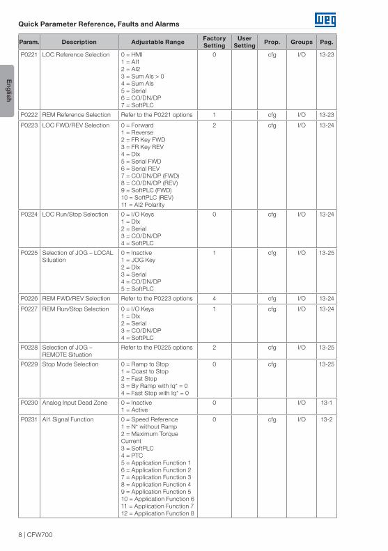
P0221 LOC Reference Selection 0 = HMI 1 = AI1 2 = AI2 3 = Sum AIs > 0 4 = Sum AIs 5 = Serial 6 = CO/DN/DP 7 = SoftPLC
0 cfg I/O 13-23
P0222 REM Reference Selection Refer to the P0221 options 1 cfg I/O 13-23
P0223 LOC FWD/REV Selection 0 = Forward1 = Reverse2 = FR Key FWD3 = FR Key REV4 = DIx5 = Serial FWD6 = Serial REV7 = CO/DN/DP (FWD) 8 = CO/DN/DP (REV) 9 = SoftPLC (FWD) 10 = SoftPLC (REV) 11 = AI2 Polarity
2 cfg I/O 13-24
P0224 LOC Run/Stop Selection 0 = I/O Keys1 = DIx2 = Serial3 = CO/DN/DP4 = SoftPLC
0 cfg I/O 13-24
P0225 Selection of JOG – LOCAL Situation
0 = Inactive1 = JOG Key2 = DIx3 = Serial4 = CO/DN/DP5 = SoftPLC
1 cfg I/O 13-25
P0226 REM FWD/REV Selection Refer to the P0223 options 4 cfg I/O 13-24
P0227 REM Run/Stop Selection 0 = I/O Keys1 = DIx2 = Serial3 = CO/DN/DP4 = SoftPLC
1 cfg I/O 13-24
P0228 Selection of JOG – REMOTE Situation
Refer to the P0225 options 2 cfg I/O 13-25
P0229 Stop Mode Selection 0 = Ramp to Stop 1 = Coast to Stop 2 = Fast Stop 3 = By Ramp with Iq* = 04 = Fast Stop with Iq* = 0
0 cfg 13-25
P0230 Analog Input Dead Zone 0 = Inactive1 = Active
0 I/O 13-1
P0231 AI1 Signal Function 0 = Speed Reference1 = N* without Ramp2 = Maximum Torque Current3 = SoftPLC4 = PTC5 = Application Function 16 = Application Function 27 = Application Function 38 = Application Function 49 = Application Function 510 = Application Function 611 = Application Function 712 = Application Function 8
0 cfg I/O 13-2

CFW700 | 9
Quick Parameter Reference, Faults and Alarms
Englis
h
Param. Description Adjustable Range Factory Setting
User Setting Prop. Groups Pag.
P0232 AI1 Gain 0.000 to 9.999 1.000 I/O 13-3
P0233 AI1 Signal Type 0 = 0 to 10 V / 20 mA1 = 4 to 20 mA2 = 10 V / 20 mA to 03 = 20 to 4 mA4 = -10 V to 10 V
0 cfg I/O 13-4
P0234 AI1 Offset -100.00 to 100.00 % 0.00 % I/O 13-3
P0235 AI1 Filter 0.00 to 16.00 s 0.00 s I/O 13-3
P0236 AI2 Signal Function Refer to the P0231 options 0 cfg I/O 13-2
P0237 AI2 Gain 0.000 to 9.999 1.000 I/O 13-3
P0238 AI2 Signal Type 0 = 0 to 10 V / 20 mA1 = 4 to 20 mA2 = 10 V / 20 mA to 03 = 20 to 4 mA4 = -10 V to 10 V
0 cfg I/O 13-4
P0239 AI2 Offset -100.00 to 100.00 % 0.00 % I/O 13-3
P0240 AI2 Filter 0.00 to 16.00 s 0.00 s I/O 13-3
P0246 Frequency Input Configuration
0 = Off 1 = DI3 2 = DI4
0 cfg 13-22
P0251 AO1 Function 0 = Speed Reference 1 = Total Reference2 = Real Speed3 = Torque Current Reference4 = Torque Current5 = Output Current 6 = Active Current7 = Output Power 8 = Torque Current >0 9 = Motor Torque10 = SoftPLC 11 = PTC 12 = Motor I x t13 = Encoder Speed14 = P0696 Value15 = P0697 Value16 = Id* Current17 = Application Function 118 = Application Function 219 = Application Function 320 = Application Function 421 = Application Function 522 = Application Function 623 = Application Function 724 = Application Function 8
2 I/O 13-6
P0252 AO1 Gain 0.000 to 9.999 1.000 I/O 13-6
P0253 AO1 Signal Type 0 = 0 to 10 V / 20 mA1 = 4 to 20 mA2 = 10 V / 20 mA to 03 = 20 to 4 mA
0 cfg I/O 13-8
P0254 AO2 Function Refer to the P0251 options 5 I/O 13-6
P0255 AO2 Gain 0.000 to 9.999 1.000 I/O 13-6
P0256 AO2 Signal Type 0 = 0 to 10 V / 20 mA1 = 4 to 20 mA2 = 10 V / 20 mA to 03 = 20 to 4 mA
0 cfg I/O 13-8

10 | CFW700
Quick Parameter Reference, Faults and Alarms
English
Param. Description Adjustable Range Factory Setting
User Setting Prop. Groups Pag.
P0263 DI1 Function 0 = Not Used 1 = Run/Stop 2 = General Enable 3 = Fast Stop 4 = FWD/REV 5 = LOC/REM 6 = JOG 7 = SoftPLC 8 = Ramp 29 = Speed/Torque10 = JOG+ 11 = JOG- 12 = No External Alarm 13 = No External Fault 14 = Reset 15 = Flying Start Disabling16 = DC Link Regulator 17 = Program. Disabling 18 = Load User 1 19 = Load User 2 20 = Application Function 121 = Application Function 212 = Application Function 323 = Application Function 424 = Application Function 525 = Application Function 626 = Application Function 727 = Application Function 8 28 = Application Function 929 = Application Function 10 30 = Application Function 1131 = Application Function 12
1 cfg I/O 13-10
P0264 DI2 Function Refer to the P0263 options 4 cfg I/O 13-10
P0265 DI3 Function Refer to the P0263 options 0 cfg I/O 13-10
P0266 DI4 Function Refer to the P0263 options 0 cfg I/O 13-10
P0267 DI5 Function Refer to the P0263 options 6 cfg I/O 13-10
P0268 DI6 Function Refer to the P0263 options 8 cfg I/O 13-10
P0269 DI7 Function Refer to the P0263 options 0 cfg I/O 13-10
P0270 DI8 Function Refer to the P0263 options 0 cfg I/O 13-10

CFW700 | 11
Quick Parameter Reference, Faults and Alarms
Englis
h
Param. Description Adjustable Range Factory Setting
User Setting Prop. Groups Pag.
P0275 DO1 Function (RL1) 0 = Not Used 1 = N* > Nx 2 = N > Nx 3 = N < Ny 4 = N = N* 5 = Zero Speed 6 = Is > Ix 7 = Is < Ix 8 = Torque > Tx 9 = Torque < Tx 10 = Remote11 = Run 12 = Ready 13 = No Fault14 = No F0070 15 = No F0071 16 = No F0006/21/22 17 = No F0051 18 = No F0072 19 = 4-20 mA OK 20 = P0695 Value21 = Forward 22 = Ride-Through 23 = Pre-Charge OK 24 = Fault 25 = Enabled Time > Hx 26 = SoftPLC 27 = N > Nx / Nt > Nx 28 = F > Fx (1) 29 = F > Fx (2) 30 = STO 31 = No F0160 32 = No Alarm33 = No Fault/Alarm 34 = Application Function 135 = Application Function 236 = Application Function 337 = Application Function 438 = Application Function 539 = Application Function 640 = Application Function 741 = Application Function 8 42 = Self-tuning
13 cfg I/O 13-15
P0276 DO2 Function Refer to the P0275 options 2 cfg I/O 13-15
P0277 DO3 Function Refer to the P0275 options 1 cfg I/O 13-15
P0278 DO4 Function Refer to the P0275 options 0 cfg I/O 13-15
P0279 DO5 Function Refer to the P0275 options 0 cfg I/O 13-15
P0281 Fx Frequency 0.0 to 300.0 Hz 4.0 Hz 13-19
P0282 Fx Hysteresis 0.0 to 15.0 Hz 2.0 Hz 13-20
P0287 Nx/Ny Hysteresis 0 to 900 rpm 18 (15) rpm 13-20
P0288 Nx Speed 0 to 18000 rpm 120 (100) rpm
13-20
P0289 Ny Speed 0 to 18000 rpm 1800 (1500) rpm
13-20
P0290 Ix Current 0 to 2 x Inom-ND 1.0 x Inom-ND 13-20
P0291 Zero Speed 0 to 18000 rpm 18 (15) rpm 13-21
P0292 N = N* Band 0 to 18000 rpm 18 (15) rpm 13-21
P0293 Tx Torque 0 to 200 % 100 % 13-21
P0294 Hx Time 0 to 6553 h 4320 h 13-21

12 | CFW700
Quick Parameter Reference, Faults and Alarms
English
Param. Description Adjustable Range Factory Setting
User Setting Prop. Groups Pag.
P0295 ND/HD VFD Rated Current 0 = 2 A / 2 A 1 = 3.6 A / 3.6 A 2 = 5 A / 5 A 3 = 6 A / 5 A 4 = 7 A / 5.5 A 5 = 7 A / 7 A 6 = 10 A / 8 A 7 = 10 A / 10 A 8 = 13 A / 11 A 9 = 13.5 A / 11 A 10 = 16 A / 13 A 11 = 17 A / 13.5 A 12 = 24 A / 19 A 13 = 24 A / 20 A 14 = 28 A / 24 A 15 = 31 A / 25 A 16 = 33.5 A / 28 A 17 = 38 A / 33 A 18 = 45 A / 36 A 19 = 45 A / 38 A 20 = 54 A / 45 A 21 = 58.5 A / 47 A 22 = 70 A / 56 A 23 = 70.5 A / 61 A 24 = 86 A / 70 A 25 = 88 A / 73 A 26 = 105 A / 86 A 27 = 105 A / 88 A 28 = 142 A / 115 A 29 = 180 A / 142 A30 = 211 A / 180 A 31 = 2.9 A / 2.7 A 32 = 4.2 A / 3.8 A 33 = 7 A / 6.5 A 34 = 10 A / 9 A 35 = 12 A / 10 A 36 = 17 A / 17 A 37 = 22 A / 19 A 38 = 27 A / 22 A 39 = 32 A / 27 A 40 = 44 A / 36 A 41 = 53 A / 44 A 42 = 63 A / 53 A 43 = 80 A / 66 A 44 = 107 A / 90 A 45 = 125 A / 107 A 46 = 150 A / 122 A
ro READ 6-5
P0296 Line Rated Voltage 0 = 200 / 240 V 1 = 380 V 2 = 400 / 415 V 3 = 440 / 460 V 4 = 480 V 5 = 500 / 525 V 6 = 550 / 575 V 7 = 600 V
According to the
inverter model
cfg 6-6
P0297 Switching Frequency 0 = 1.25 kHz 1 = 2.5 kHz 2 = 5.0 kHz 3 = 10.0 kHz 4 = 2.0 kHz
According to the
inverter model
cfg 6-6
P0298 Application 0 = Normal Duty (ND) 1 = Heavy Duty (HD)
0 cfg 6-7

CFW700 | 13
Quick Parameter Reference, Faults and Alarms
Englis
h
Param. Description Adjustable Range Factory Setting
User Setting Prop. Groups Pag.
P0299 Starting DC-Braking Time 0.0 to 15.0 s 0.0 s V/f, VVW, Sless
12-15
P0300 Stopping DC-Braking Time 0.0 to 15.0 s 0.0 s V/f, VVW, Sless
12-15
P0301 DC-Braking Speed 0 to 450 rpm 30 rpm V/f, VVW, Sless
12-17
P0302 DC-Braking Voltage 0.0 to 10.0 % 2.0 % V/f, VVW 12-17
P0303 Skip Speed 1 0 to 18000 rpm 600 rpm 12-18
P0304 Skip Speed 2 0 to 18000 rpm 900 rpm 12-18
P0305 Skip Speed 3 0 to 18000 rpm 1200 rpm 12-18
P0306 Skip Band 0 to 750 rpm 0 rpm 12-18
P0308 Serial Address 1 to 247 1 NET 17-1
P0310 Serial Baud Rate 0 = 9600 bits/s1 = 19200 bits/s2 = 38400 bits/s3 = 57600 bits/s
1 NET 17-1
P0311 Serial Byte Configuration 0 = 8 bits, no, 1 1 = 8 bits, even, 1 2 = 8 bits, odd, 1 3 = 8 bits, no, 2 4 = 8 bits, even, 2 5 = 8 bits, odd, 2
1 NET 17-1
P0313 Communication Error Action
0 = Off1 = Ramp Stop2 = General Disable3 = Goes to LOC4 = LOC Keeping Enabled5 = Causes Fault
1 NET 17-3
P0314 Serial Watchdog 0.0 to 999.0 s 0.0 s NET 17-1
P0316 Serial Interface Status 0 = Off1 = On2 = Watchdog Error
ro NET 17-1
P0317 Oriented Start-up 0 = No1 = Yes
0 cfg STARTUP 7-2
P0318 Copy Function MMF 0 = Off1 = VFD → MMF2 = MMF → VFD3 = VFD Synchronization → MMF 4 = MMF Format 5 = SoftPLC Program Copy 6= SoftPLC Program Save
0 cfg 7-2
P0320 FlyStart/Ride-Through 0 = Off1 = Flying Start2 = FS / RT3 = Ride-Through
0 cfg 12-8
P0321 DC Link Power Loss 178 to 770 V 505 V Vector 12-13
P0322 DC Link Ride-Through 178 to 770 V 490 V Vector 12-13
P0323 DC Link Power Back 178 to 770 V 535 V Vector 12-13
P0325 Ride-Through P Gain 0.0 to 63.9 22.8 Vector 12-14
P0326 Ride-Through I Gain 0.000 to 9.999 0.128 Vector 12-14
P0327 FS I/f Current Ramp 0.000 to 1.000 s 0.070 Sless 12-9
P0328 Flying Start Filter 0.000 to 1.000 s 0.085 Sless 12-9

14 | CFW700
Quick Parameter Reference, Faults and Alarms
English
Param. Description Adjustable Range Factory Setting
User Setting Prop. Groups Pag.
P0329 FS I/f Frequency Ramp 2.0 to 50.0 20.0 Sless 12-9
P0331 Voltage Ramp 0.2 to 60.0 s 2.0 s V/f, VVW 12-11
P0332 Dead Time 0.1 to 10.0 s 1.0 s V/f, VVW 12-11
P0340 Auto-Reset Time 0 to 255 s 0 s 15-8
P0343 Ground Fault Configuration 0 = Off1 = On
1 cfg 15-8
P0344 Current Limit Configuration 0 = Hold 1 = Decel.
1 cfg, V/f, VVW
9-6
P0348 Motor Overload Configuration
0 = Off 1 = Fault/Alarm 2 = Fault 3 = Alarm
1 cfg 15-8
P0349 I x t Alarm Level 70 to 100 % 85 % cfg 15-9
P0350 IGBT Overload Configuration
0 = F, w/ SF rd. 1 = F/A, w/ SF rd. 2 = F, no SF rd. 3 = F/A, no SF rd.
1 cfg 15-9
P0351 Motor Overtemperature Config.
0 = Off 1 = Fault/Alarm 2 = Fault 3 = Alarm
1 cfg 15-10
P0352 Fan Control Configuration 0 = HS-OFF, Int-OFF 1 = HS-ON, Int-ON 2 = HS-CT, Int-CT 3 = HS-CT, Int-OFF 4 = HS-CT, Int-ON 5 = HS-ON, Int-OFF 6 = HS-ON, Int-CT 7 = HS-OFF, Int-ON 8 = HS-OFF, Int-CT9 = HS-CT, Int -CT *10 = HS-CT, Int -OFF *11 = HS-CT, Int -ON *12 = HS-ON, Int -CT *13 = HS-OFF, Int -CT *
2 cfg 15-11
P0353 IGBTs/Air Overtemp. Config.
0 = HS-F/A, Air-F/A 1 = HS-F/A, Air-F 2 = HS-F, Air-F/A 3 = HS-F, Air-F 4 = HS-F/A, Air-F/A *5 = HS-F/A, Air-F *6 = HS-F, Air-F/A *7 = HS-F, Air-F *
0 cfg 15-12
P0354 Fan Speed Configuration 0 = Inactive1 = Fault
1 cfg 15-12
P0355 Config. of Fault F0185 0 = Off1 = On
1 cfg 15-13
P0356 Dead Time Compensation 0 = Inactive1 = Active
1 cfg 15-13
P0357 Line Phase Loss Time 0 to 60 s 3 s 15-13
P0358 Encoder Fault Config. 0 = Off1 = F0067 ON2 = F0079 ON3 = F0067, F0079 ON
3 cfg, Enc 15-13
P0360 Speed Hysteresis 0.0 to 100.0 % 10.0 % Vector 11-23
P0361 Time with Speed different from Reference
0.0 to 999.0 s 0.0 s Vector 11-23
P0372 Sless DC Braking Current 0.0 to 90.0 % 40.0 % Sless 12-17

CFW700 | 15
Quick Parameter Reference, Faults and Alarms
Englis
h
Param. Description Adjustable Range Factory Setting
User Setting Prop. Groups Pag.
P0397 Regen. Slip Compensation 0 = Off1 = On
1 cfg, VVW
10-3
P0398 Motor Service Factor 1.00 to 1.50 1.00 cfg MOTOR 11-9
P0399 Motor Rated Efficiency 50.0 to 99.9 % 67.0 % cfg, VVW
MOTOR 10-3
P0400 Motor Rated Voltage 0 to 600 V 440 V cfg MOTOR 11-9
P0401 Motor Rated Current 0 to 1.3 x Inom-ND 1.0 x Inom-ND cfg MOTOR 11-9
P0402 Motor Rated Speed 0 to 18000 rpm 1750 (1458) rpm
cfg MOTOR 11-10
P0403 Motor Rated Frequency 0 to 300 Hz 60 (50) Hz cfg MOTOR 11-10
P0404 Motor Rated Power 0 = 0.33 HP 0.25 kW 1 = 0.5 HP 0.37 kW 2 = 0.75 HP 0.55 kW 3 = 1 HP 0.75 kW 4 = 1.5 HP 1.1 kW 5 = 2 HP 1.5 kW 6 = 3 HP 2.2 kW 7 = 4 HP 3 kW 8 = 5 HP 3.7 kW 9 = 5.5 HP 4 kW 10 = 6 HP 4.5 kW 11 = 7.5 HP 5.5 kW 12 = 10 HP 7.5 kW 13 = 12.5 HP 9 kW 14 = 15 HP 11 kW 15 = 20 HP 15 kW 16 = 25 HP 18.5 kW 17 = 30 HP 22 kW 18 = 40 HP 30 kW 19 = 50 HP 37 kW 20 = 60 HP 45 kW 21 = 75 HP 55 kW 22 = 100 HP 75 kW 23 = 125 HP 90 kW 24 = 150 HP 110 kW 25 = 175 HP 130 kW
Motormax-ND cfg MOTOR 11-10
P0405 Encoder Pulse Number 100 to 9999 ppr 1024 ppr cfg MOTOR 11-11
P0406 Motor Ventilation 0 = Self-Ventilated1 = Separated Ventilation2 = Optimal Flux 3 = Extended Protection
0 cfg MOTOR 11-11
P0407 Motor Rated Power Factor 0.50 to 0.99 0.68 cfg, VVW
MOTOR 9-1210-4
P0408 Run Self-Tuning 0 = No 1 = No Rotation 2 = Run for Im 3 = Run for Tm 4 = Estimate Tm
0 cfg, VVW, Vector
MOTOR 11-18
P0409 Stator Resistance 0.000 to 9.999 ohm 0.000 ohm cfg, VVW, Vector
MOTOR 11-19
P0410 Magnetization Current 0 to 1.25 x Inom-ND Inom-ND MOTOR 11-20
P0411 Leakage Inductance 0.00 to 99.99 mH 0.00 mH cfg, Vector
MOTOR 11-20
P0412 Tr Time Constant 0.000 to 9.999 s 0.000 s Vector MOTOR 11-20
P0413 Tm Time Constant 0.00 to 99.99 s 0.00 s Vector MOTOR 11-21

16 | CFW700
Quick Parameter Reference, Faults and Alarms
English
Param. Description Adjustable Range Factory Setting
User Setting Prop. Groups Pag.
P0510 Ind. 1 Engineering Unit 0 = None1 = V2 = A3 = rpm4 = s5 = ms6 = N7 = m8 = Nm9 = mA10 = %11 = °C12 = CV13 = Hz14 = HP15 = h16 = W17 = kW18 = kWh19 = H
0 HMI 5-5
P0511 Ind. Decimal Point 1 0 = wxyz 1 = wxy.z2 = wx.yz3 = w.xyz
1 HMI 5-6
P0512 Ind. Eng. Unit 2 See options in P0510 11 HMI 5-7
P0513 Ind. Decimal Point 2 0 = wxyz1 = wxy.z2 = wx.yz3 = w.xyz
1 HMI 5-7
P0514 Ind. Eng. Unit 3 See options in P0510 10 HMI 5-8
P0515 Ind. Decimal Point 3 0 = wxyz 1 = wxy.z2 = wx.yz3 = w.xyz
1 HMI 5-8
P0516 Ind. Eng. Unit 4 See options in P0510 13 HMI 5-9
P0517 Ind. Decimal Point 4 0 = wxyz 1 = wxy.z2 = wx.yz3 = w.xyz
1 HMI 5-9
P0588 Maximum Torque Level 0 to 85 % 0 % cfg, V/f 9-12
P0589 Level of Minimum Applied Voltage
40 to 80 % 40 % cfg, V/f 9-12
P0590 Minimum Speed Level 0 to 18000 rpm 600 (525) rpm
cfg, V/f 9-13
P0591 Hysteresis for the Maximum Torque Level
0 to 30 % 10 % cfg, V/f 9-13
CFW700 | 17
Quick Parameter Reference, Faults and Alarms
Englis
h
Param. Description Adjustable Range Factory Setting
User Setting Prop. Groups Pag.
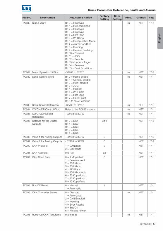
P0680 Status Word Bit 0 = ReservedBit 1 = Run commandBit 2 = ReservedBit 3 = ReservedBit 4 = Fast StopBit 5 = 2nd RampBit 6 = Configuration ModeBit 7 = Alarm ConditionBit 8 = Running Bit 9 = General EnablingBit 10 = ForwardBit 11 = JOG Bit 12 = RemoteBit 13 = UndervoltageBit 14 = ReservedBit 15 = Fault Condition
ro NET 17-3
P0681 Motor Speed in 13 Bits -32768 to 32767 ro NET 17-3
P0682 Serial Control Word Bit 0 = Ramp Enable Bit 1 = General EnableBit 2 = Run Forward Bit 3 = JOGBit 4 = Remote Bit 5 = 2nd Ramp Bit 6 = Fast StopBit 7 = Fault ResetBit 8 to 15 = Reserved
ro NET 17-1
P0683 Serial Speed Reference -32768 to 32767 ro NET 17-1
P0684 CO/DN/DP Control Word Refer to the P0682 options ro NET 17-1
P0685 CO/DN/DP Speed Reference
- 32768 to 32767 ro NET 17-1
P0695 Settings for the Digital Outputs
Bit 0 = DO1 Bit 1 = DO2 Bit 2 = DO3 Bit 3 = DO4 Bit 4 = DO5
Bit 4 NET 17-3
P0696 Value 1 for Analog Outputs - 32768 to 32767 0 NET 17-3
P0697 Value 2 for Analog Outputs - 32768 to 32767 0 NET 17-3
P0700 CAN Protocol 1 = CANopen2 = DeviceNet
2 NET 17-1
P0701 CAN Address 0 to 127 63 NET 17-1
P0702 CAN Baud Rate 0 = 1 Mbps/Auto 1 = Reserved/Auto 2 = 500 Kbps 3 = 250 Kbps 4 = 125 Kbps 5 = 100 Kbps/Auto 6 = 50 Kbps/Auto 7 = 20 Kbps/Auto 8 = 10 Kbps/Auto
0 NET 17-1
P0703 Bus Off Reset 0 = Manual1 = Automatic
1 NET 17-1
P0705 CAN Controller Status 0 = Disabled1 = Auto-baud2 = CAN Enabled3 = Warning4 = Error Passive5 = Bus Off6 = No Bus Power
ro NET 17-1
P0706 Received CAN Telegrams 0 to 65535 ro NET 17-1

18 | CFW700
Quick Parameter Reference, Faults and Alarms
English
Param. Description Adjustable Range Factory Setting
User Setting Prop. Groups Pag.
P0707 Transmitted CAN Telegrams
0 to 65535 ro NET 17-1
P0708 Bus Off Counter 0 to 65535 ro NET 17-1
P0709 Lost CAN Messages 0 to 65535 ro NET 17-1
P0710 DeviceNet I/O Instances 0 = ODVA Basic 2W1 = ODVA Extended 2W2 = Manuf. Spec. 2W3 = Manuf. Spec. 3W4 = Manuf. Spec. 4W5 = Manuf. Spec. 5W6 = Manuf. Spec. 6W
0 NET 17-1
P0711 DeviceNet Reading Word # 3 0 to 1199 0 NET 17-2
P0712 DeviceNet Reading Word # 4 0 to 1199 0 NET 17-2
P0713 DeviceNet Reading Word # 5 0 to 1199 0 NET 17-2
P0714 DeviceNet Reading Word # 6 0 to 1199 0 NET 17-2
P0715 DeviceNet Writing Word # 3 0 to 1199 0 NET 17-2
P0716 DeviceNet Writing Word # 4 0 to 1199 0 NET 17-2
P0717 DeviceNet Writing Word # 5 0 to 1199 0 NET 17-2
P0718 DeviceNet Writing Word # 6 0 to 1199 0 NET 17-2
P0719 DeviceNet Network Status 0 = Offline1 = Online, Not Connected2 = Online, Connected3 = Timed-out Connection4 = Connection Failure5 = Auto-Baud
ro NET 17-2
P0720 DeviceNet Master Status 0 = Run1 = Idle
ro NET 17-2
P0721 CANopen Com. Status 0 = Disabled1 = Reserved2 = Com. Enabled3 = Error Control Enabled4 = Guarding Error5 = Heartbeat Error
ro NET 17-2
P0722 CANopen Node Status 0 = Disabled1 = Initialization2 = Stopped3 = Operational4 = Preoperational
ro NET 17-2
P0740 Profibus Communication Status
0 = Inactive 1 = Access Error 2 = Offline 3 = Configuration Error 4 = Parameterization Error 5 = Clear Mode 6 = Online
ro NET 17-2
P0741 Profibus Data Profile 0 = PROFIdrive1 = Manufacturer
1 NET 17-2
P0742 Profibus Reading # 3 0 to 1199 0 NET 17-2
P0743 Profibus Reading # 4 0 to 1199 0 NET 17-2
P0744 Profibus Reading # 5 0 to 1199 0 NET 17-2
P0745 Profibus Reading # 6 0 to 1199 0 NET 17-2
P0746 Profibus Reading # 7 0 to 1199 0 NET 17-2
P0747 Profibus Reading # 8 0 to 1199 0 NET 17-2
P0748 Profibus Reading # 9 0 to 1199 0 NET 17-2
P0749 Profibus Reading # 10 0 to 1199 0 NET 17-2

CFW700 | 19
Quick Parameter Reference, Faults and Alarms
Englis
h
Param. Description Adjustable Range Factory Setting
User Setting Prop. Groups Pag.
P0750 Profibus Writing # 3 0 to 1199 0 NET 17-3
P0751 Profibus Writing # 4 0 to 1199 0 NET 17-3
P0752 Profibus Writing # 5 0 to 1199 0 NET 17-3
P0753 Profibus Writing # 6 0 to 1199 0 NET 17-3
P0754 Profibus Writing # 7 0 to 1199 0 NET 17-3
P0755 Profibus Writing # 8 0 to 1199 0 NET 17-3
P0756 Profibus Writing # 9 0 to 1199 0 NET 17-3
P0757 Profibus Writing # 10 0 to 1199 0 NET 17-3
P0918 Profibus Address 1 to 126 1 NET 17-3
P0922 Profibus Telegram Selection 1 = Standard Telegram 12 = Telegram 100 3 = Telegram 1014 = Telegram 1025 = Telegram 1036 = Telegram 1047 = Telegram 1058 = Telegram 1069 = Telegram 107
1 NET 17-3
P0944 Fault Counter 0 to 65535 ro NET 17-3
P0947 Fault Number 0 to 65535 ro NET 17-3
P0963 Profibus Baud Rate 0 = 9.6 kbit/s1 = 19.2 kbit/s2 = 93.75kbit/s3 = 187.5 kbit/s4 = 500 kbit/s5 = Not detected6 = 1500 kbit/s7 = 3000 kbit/s8 = 6000 kbit/s9 = 12000 kbit/s10 = Reserved11 = 45.45 kbit/s
ro NET 17-3
P0964 Drive Identification 0 to 65535 ro NET 17-3
P0965 Profile Identification 0 to 65535 ro NET 17-3
P0967 Control Word 1 0000h to FFFFh 0000h ro NET 17-3
P0968 Status Word 1 0000h to FFFFh 0000h ro NET 17-3
P1000 SoftPLC Status 0 = No Applicative1 = Installing App.2 = Incompatible App.3 = Stopped Applicative4 = Applicative Running
ro SPLC, READ
18-1
P1001 SoftPLC Command 0 = Stop Applicative1 = Run Applicative2 = Delete Applicative
0 SPLC 18-1
P1002 Scan Cycle Time 0.0 to 999.9 ms ro READ, SPLC
18-1
P1003 Applicative Selection 0 = User1 = PID Controller2 = EP3 = Multispeed4 = 3-Wire Start/Stop5 = FWD Run/ REV Run6 = Special Function Set
0 cfg SPLC 18-2
P1008 Lag Error -9999 to 9999 ro, Enc SPLC 18-2
P1009 Position Gain 0 to 9999 10 Enc SPLC 18-3
P1010 SoftPLC Parameter 1 -32768 to 32767 0 cfg SPLC 18-3

20 | CFW700
Quick Parameter Reference, Faults and Alarms
English
Param. Description Adjustable Range Factory Setting
User Setting Prop. Groups Pag.
P1011 SoftPLC Parameter 2 -32768 to 32767 0 cfg SPLC 18-3
P1012 SoftPLC Parameter 3 -32768 to 32767 0 cfg SPLC 18-3
P1013 SoftPLC Parameter 4 -32768 to 32767 0 cfg SPLC 18-3
P1014 SoftPLC Parameter 5 -32768 to 32767 0 cfg SPLC 18-3
P1015 SoftPLC Parameter 6 -32768 to 32767 0 cfg SPLC 18-3
P1016 SoftPLC Parameter 7 -32768 to 32767 0 cfg SPLC 18-3
P1017 SoftPLC Parameter 8 -32768 to 32767 0 cfg SPLC 18-3
P1018 SoftPLC Parameter 9 -32768 to 32767 0 cfg SPLC 18-3
P1019 SoftPLC Parameter 10 -32768 to 32767 0 cfg SPLC 18-3
P1020 SoftPLC Parameter 11 -32768 to 32767 0 cfg SPLC 18-3
P1021 SoftPLC Parameter 12 -32768 to 32767 0 cfg SPLC 18-3
P1022 SoftPLC Parameter 13 -32768 to 32767 0 cfg SPLC 18-3
P1023 SoftPLC Parameter 14 -32768 to 32767 0 cfg SPLC 18-3
P1024 SoftPLC Parameter 15 -32768 to 32767 0 cfg SPLC 18-3
P1025 SoftPLC Parameter 16 -32768 to 32767 0 cfg SPLC 18-3
P1026 SoftPLC Parameter 17 -32768 to 32767 0 cfg SPLC 18-3
P1027 SoftPLC Parameter 18 -32768 to 32767 0 cfg SPLC 18-3
P1028 SoftPLC Parameter 19 -32768 to 32767 0 cfg SPLC 18-3
P1029 SoftPLC Parameter 20 -32768 to 32767 0 cfg SPLC 18-3
P1030 SoftPLC Parameter 21 -32768 to 32767 0 cfg SPLC 18-3
P1031 SoftPLC Parameter 22 -32768 to 32767 0 cfg SPLC 18-3
P1032 SoftPLC Parameter 23 -32768 to 32767 0 cfg SPLC 18-3
P1033 SoftPLC Parameter 24 -32768 to 32767 0 cfg SPLC 18-3
P1034 SoftPLC Parameter 25 -32768 to 32767 0 cfg SPLC 18-3
P1035 SoftPLC Parameter 26 -32768 to 32767 0 cfg SPLC 18-3
P1036 SoftPLC Parameter 27 -32768 to 32767 0 cfg SPLC 18-3
P1037 SoftPLC Parameter 28 -32768 to 32767 0 cfg SPLC 18-3
P1038 SoftPLC Parameter 29 -32768 to 32767 0 cfg SPLC 18-3
P1039 SoftPLC Parameter 30 -32768 to 32767 0 cfg SPLC 18-3
P1040 SoftPLC Parameter 31 -32768 to 32767 0 cfg SPLC 18-3
P1041 SoftPLC Parameter 32 -32768 to 32767 0 cfg SPLC 18-3
P1042 SoftPLC Parameter 33 -32768 to 32767 0 cfg SPLC 18-3
P1043 SoftPLC Parameter 34 -32768 to 32767 0 cfg SPLC 18-3
P1044 SoftPLC Parameter 35 -32768 to 32767 0 cfg SPLC 18-3
P1045 SoftPLC Parameter 36 -32768 to 32767 0 cfg SPLC 18-3
P1046 SoftPLC Parameter 37 -32768 to 32767 0 cfg SPLC 18-3
P1047 SoftPLC Parameter 38 -32768 to 32767 0 cfg SPLC 18-3
P1048 SoftPLC Parameter 39 -32768 to 32767 0 cfg SPLC 18-3
P1049 SoftPLC Parameter 40 -32768 to 32767 0 cfg SPLC 18-3
P1050 SoftPLC Parameter 41 -32768 to 32767 0 cfg SPLC 18-3
P1051 SoftPLC Parameter 42 -32768 to 32767 0 cfg SPLC 18-3
P1052 SoftPLC Parameter 43 -32768 to 32767 0 cfg SPLC 18-3
P1053 SoftPLC Parameter 44 -32768 to 32767 0 cfg SPLC 18-3
P1054 SoftPLC Parameter 45 -32768 to 32767 0 cfg SPLC 18-3
P1055 SoftPLC Parameter 46 -32768 to 32767 0 cfg SPLC 18-3

CFW700 | 21
Quick Parameter Reference, Faults and Alarms
Englis
h
Param. Description Adjustable Range Factory Setting
User Setting Prop. Groups Pag.
P1056 SoftPLC Parameter 47 -32768 to 32767 0 cfg SPLC 18-3
P1057 SoftPLC Parameter 48 -32768 to 32767 0 cfg SPLC 18-3
P1058 SoftPLC Parameter 49 -32768 to 32767 0 cfg SPLC 18-3
P1059 SoftPLC Parameter 50 -32768 to 32767 0 cfg SPLC 18-3
Notes:ro = Read-only parameter.rw = Reading/writing parameter.cfg = Configuration parameter, it can be changed only with stopped motor.V/f = Parameter available in V/f mode.Adj = Parameter available only in adjustable V/f mode.VVW = Parameter available in VVW mode.Vector = Parameter available in vector mode.Sless = Parameter available only in sensorless mode.Enc = Parameter available only in vector mode with encoder.

22 | CFW700
Quick Parameter Reference, Faults and Alarms
English
Fault/Alarm Description Possible Causes
F0006:Input Voltage Imbalance or Phase Loss
The mains voltage imbalance is too high or phase loss at the supply line has occurred.Note:- This fault may not occur if the load at the motor shaft is too low or nonexistent.P0357 sets the time for the trip, and P0357 = 0 disables this fault.
A Phase Loss at the inverter input. The input voltage imbalance is > 5 %.
F0021:DC Link Undervoltage
A DC link undervoltage condition has occurred.
The input voltage is too low and the DC link voltage dropped below the minimum permitted value (monitor the P0004 parameter value): Ud < 223 V - 200 / 240 V three-phase input voltage. Ud < 170 V - 200 / 240 V single-phase input voltage (CFW700XXXXS2 or CFW700XXXXB2 models) (P0296 = 0). Ud < 385 V - 380 V input voltage (P0296 = 1). Ud < 405 V - 400 / 415 V input voltage (P0296 = 2). Ud < 446 V - 440 / 460 V input voltage (P0296 = 3). Ud < 487 V - 480 V input voltage (P0296 = 4). Ud < 530 V - input voltage 500 / 525 V (P0296 = 5). Ud < 580 V - input voltage 550 / 575 V (P0296 = 6). Ud < 605 V - input voltage 600 V (P0296 = 7).
Phase loss at the inverter input. Pre-charge circuit failure. Parameter P0296 was set to a value higher than the power supply rated voltage.
F0022: DC Link Overvoltage
A DC link overvoltage condition has occurred.
Too high input voltage, resulting in a DC link voltage higher than the maximum permitted value: Ud > 400 V - 220 / 230 V models (P0296 = 0). Ud > 800 V - 380 / 480 V models (P0296 = 1, 2, 3, or 4). Ud > 1000 V - 500 / 600 V models (P0296 = 5, 6 or 7).
The inertia of the driven-load is too high or the deceleration time is too short.
The parameter P0151, P0153 or P0185 setting is too high.
A0046: High Load at the Motor
It is the motor overload alarm.Note:It can be disabled by setting P0348 = 0 or 2.
The settings of P0156, P0157 and P0158 are too low for the used motor.
There is excessive load at the motor shaft.
A0047: IGBT Overload Alarm
It is the IGBT overload alarm.Note:It can be disabled by setting P0350 = 0 or 2.
The inverter output current is too high.
F0048: IGBT Overload Fault
It is the IGBT overload fault. The inverter output current is too high.
A0050: IGBT High Temperature
The NTC temperature sensors located in the IGBTs detected a high temperature alarm. Note: It can be disabled by setting P0353 = 2 or 3.
High surrounding air temperature (>50 °C (122 °F)) and high output current.
Blocked or defective fan. Very dirty heatsink.
F0051: IGBT Overtemperature
The NTC temperature sensors located in the IGBTs detected a high temperature fault.
F0067: Inverted Encoder/Motor Wiring
Fault related to the phase relationship between the encoder signals, if P0202 = 5 and P0408 = 2, 3 or 4. Note: - It is not possible to reset this fault (when P0408>1).- In this case, turn off the power supply, solve the problem, and then turn it on again.- When P0408 = 0, it is possible to reset this fault. This fault could be disabled by means of parameter P0358.
Output motor cables U, V, W are inverted. Encoder channels A and B are inverted. Error in the encoder mounting position.

CFW700 | 23
Quick Parameter Reference, Faults and Alarms
Englis
h
Fault/Alarm Description Possible Causes
F0070: Overcurrent/Short-circuit
An overcurrent or a short-circuit at the output, at the DC link or at the braking resistor, has occurred.
Short-circuit between two motor phases. Short-circuit between the dynamic braking resistor connection cables.
Shorted IGBT modules.
F0071: Output Overcurrent
An output overcurrent has occurred. Excessive load inertia or too short acceleration ramp. P0135, or P0169 and P0170 settings are too high.
F0072: Motor Overload
The motor overload protection has tripped.Note:It can be disabled by setting P0348 = 0 or 3.
The settings of P0156, P0157 and P0158 are too low for the used motor.
There is excessive load at the motor shaft.
F0074: Ground Fault
A ground fault occurred either in the cable between the inverter and the motor or in the motor itself. Note: It can be disabled by setting P0343 = 0.
Short-circuit to the ground in one or more output phases.
Motor cable capacitance is too large, resulting in current peaks at the output.
F0078: Motor Overtemperature
Fault related to the PTC temperature sensor installed in the motor. Note:- It can be disabled by setting P0351 = 0 or 3.- An analog input and an analog output must be set for the PTC function.
Excessive load at the motor shaft. Severe duty cycle (too many Starts/Stops per minute).
Too high surrounding air temperature. Loose connection or short-circuit (resistance < 100 Ω) in the wiring connected to the motor thermistors.
Not installed motor thermistors. Blocked motor shaft.
F0079:Encoder Signal Fault
Lack of encoder signals.Note:Detection performed only by software. The fault can be disabled by means of parameter P0358.
Broken wiring between encoder interface. Defective encoder.
F0080: CPU Watchdog
Microcontroller watchdog fault. Electrical noise.
F0084: Auto-Diagnosis Fault
Auto-Diagnosis Fault. Defect in the inverter internal circuitry. Firmware incompatible with an accessory.
A0090: External Alarm
External alarm monitored through a digital input. Note: It is necessary to program a digital input for “No external alarm”.
A digital input (DI1 to DI8) programmed for “No external alarm” is open.
F0091: External Fault
External fault monitored through a digital input. Note: It is necessary to program a digital input for “No external fault”.
A digital input (DI1 to DI8) programmed for “No external fault” is open.
A0098: Activate General Enable
General enable signal is missing during the self-tuning.
The digital input programmed for “General Enable” is open.
F0099: Invalid Current Offset
The current measurement circuit is presenting an abnormal value for null current.
Defect in the inverter internal circuitry.
A0110: High Motor Temperature
Fault detected through PTC type temperature sensors installed in the motor.Note:- It can be disabled by setting P0351 = 0 or 2.- An analog input and an analog output must be set for the PTC function.
Excessive load at the motor shaft. Severe duty cycle (too many Starts/Stops per minute).
Too high surrounding air temperature. Not installed motor thermistors. Blocked motor shaft.
A0128: Serial Communication Timeout
It indicates that the inverter stopped receiving valid telegrams during a certain period.Note:It can be disabled by setting P0314 = 0.0 s
Check the wiring and the ground installation. Make sure that the inverter has sent a new message within the time interval set at P0314.

24 | CFW700
Quick Parameter Reference, Faults and Alarms
English
Fault/Alarm Description Possible Causes
A0133: CAN Interface without Power Supply
It is the alarm indicating that the power supply is missing at the CAN controller.
Broken or disconnected cable. The power supply is turned off.
A0134: Bus Off
The inverter CAN interface has entered the buss off state.
Incorrect communication baud rate. Two network slaves with the same address. Wrong cable connection (inverted signals).
A0135: CANopen Communication Error
It indicates a communication error alarm. Communication problems. Wrong master configuration/settings. Incorrect configuration of the communication objects.
A0136: Idle Master
The network master has entered the idle state.
PLC in IDLE mode. PLC command register bit set to zero (0).
A0137: DeviceNet Connection Timeout
It is the alarm indicating timeout of the DeviceNet I/O connections.
One or more allocated I/O connections have entered the timeout state.
A0138: (2)
Profibus DP Interface in Clear Mode
It indicates that the inverter received a command from the Profibus DP network master to enter the clear mode.
Verify the network master status, making sure it is in the execution mode (Run).
Refer to the Profibus DP communication manual for more information.
A0139: (2)
Offline Profibus DP Interface
It indicates an interruption in the communication between the Profibus DP network master and the inverter.
Verify whether the network master is correctly configured and operating normally.
Verify the network installation in a general manner - cable routing, grounding.
Refer to the Profibus DP communication manual for more information.
A0140: (2)
Profibus DP Module Access Error
It indicates an error in the access to the Profibus DP communication module data.
Verify whether the Profibus DP module is correctly fit into the slot 3.
Refer to the Profibus DP communication manual for more information.
F0150: Motor Overspeed
Overspeed fault.It trips when the actual speed exceeds
the value of P0134 x (100 % + P0132)
100% for
more than 20 ms.
Wrong settings of P0161 and/or P0162. Problem with a hoist-type load.
F0151: FLASH Memory Module Fault
FLASH Memory Module (MMF-01) fault. Defective FLASH memory module. Check the connection of the FLASH memory module.
A0152: High Internal Air Temperature
This alarm indicates that the internal air temperature is too high.Note:It can be disabled by setting P0353 = 1 or 3.
High surrounding air temperature (>50 °C (122 °F)) and high output current.
Defective internal fan (if existent). High temperature (> 45 ºC) inside the cabinet.
F0153: Internal Air Overtemperature
It indicates internal air overtemperature fault.
High surrounding air temperature (>50 °C (122 °F)) and high output current.
Defective internal fan (if existent).
F0156: Undertemperature
The temperature sensors located in the IGBTs or in the rectifier detected a low temperature, below -30 °C ( -22 °F), fault.
Surrounding air temperature ≤ -30 °C (-22 °F).
F0157: Parameter Table Data Loss
There was a problem during the initialization, during the parameter table loading routine. Some recent parameter modifications may have been lost.
The control was switched off very fast while a parameter was being modified.
F0158: Parameter Table Fault
There was a problem during the initialization, during the parameter table loading routine. All the parameters were lost and the factory settings were loaded.
Firmware updating fault. Defective control board.
A0159:Incompatible HMI
Incompatible HMI HMI of another product being used.
F0160:Safety Stop Relays
STO function (Safe Torque Off) relay fault. One of the relays is defective or it does not have +24 V applied to its coil.

CFW700 | 25
Quick Parameter Reference, Faults and Alarms
Englis
h
Fault/Alarm Description Possible Causes
A0163:AI1 Broken Cable
It indicates that the AI1 current (4-20 mA or 20-4 mA) reference is out of the 4 to 20 mA range.
Broken AI1 cable. Bad contact at the connection of the signal to the terminal strip.
A0164:AI2 Broken Cable
It indicates that the AI2 current (4-20 mA or 20-4 mA) reference is out of the 4 to 20 mA range.
Broken AI2 cable. Bad contact at the connection of the signal to the terminal strip.
A0168:Speed Error too High
Difference between Speed Reference and Effective Speed greater than the setting in P0360.
Inverter in Torque Current Limitation.
F0169:Speed Error too High
Difference between Speed Reference and Effective Speed greater than the setting in P0360 for longer than P0361.
Inverter in Torque Current Limitation for too long.
A0170:Safety Stop
The STO function (Safe Torque Off) is active.
The CFW700 went to the STO state.
A0177: Fan Replacement
Fan replacement alarm (P0045 > 50000 hours). Note: This function can be disabled by setting P0354 = 0.
The heatsink fan maximum number of operating hours has been reached.
F0179: Heatsink Fan Speed Fault
This fault indicates a problem with the heatsink fan. Note: This function can be disabled by setting P0354 = 0.
Dirt on the blades and in the bearings of the fan. Defective fan. Defective fan power supply connection.
F0182: Pulse Feedback Fault
It indicates a fault in the output pulses feedback.
Defect in the inverter internal circuitry.
F0183: IGBT Overload + Temperature
Overtemperature related to the IGBT overload protection.
Too high inverter surrounding temperature. Operation with frequencies < 10 kHz with overload.
F0185:Pre-Charge Contactor Fault
It indicates a fault at the pre-charge contactor.
Defective pre-charge contactor. Open command fuse. Phase loss at the L1/R or L2/S input.
F0228:Serial Communication Timeout
Refer to the RS-232 / RS-485 Serial Communication Manual.
F0233:CAN interface without power supply
Refer to the CANopen Communication Manual and/or the DeviceNet Communication Manual.
F0234:Bus Off
F0235:CANopen Communication Error
Refer to the CANopen Communication Manual.
F0236:Idle Master
Refer to the DeviceNet Communication Manual.
F0237:DeviceNet Connection TimeoutF0238: (2)
Profibus DP Interface in Clear Mode
It indicates that the inverter received a command from the Profibus DP network master to enter the clear mode.
Verify the network master status, making sure it is in the execution mode (Run).
The fault indication will occur if P0313 = 5. Refer to the Profibus DP communication manual for more information.

26 | CFW700
Quick Parameter Reference, Faults and Alarms
English
Fault/Alarm Description Possible Causes
F0239: (2)
Offline Profibus DP Interface
I t indicates an interruption in the communication between the Profibus DP network master and the inverter.
Verify whether the network master is correctly configured and operating normally.
Verify the network installation in a general manner - cable routing, grounding.
The fault indication will occur if P0313 = 5. Refer to the Profibus DP communication manual for more information.
F0240: (2)
Profibus DP Module Access Error
It indicates an error in the access to the Profibus DP communication module data.
Verify whether the Profibus DP module is correctly fit into the slot 3.
The fault indication will occur if P0313 = 5. Refer to the Profibus DP communication manual for more information.
A0702:Disabled Inverter
Refer to the SoftPLC Manual.
A0704:Two Enabled Movements
A0706:Reference not Programmed for SoftPLC F0711:Fault in the Execution of the SoftPLC
Fault in the execution of the SoftPLC. Incompatible applicative. Fault during upload of the applicative.
Notes:(1) Very long motor cables, with more than 100 m (328.08 ft), presents a high parasitic capacitance to the ground. The
circulation of a leakage current through this capacitance may cause the activation of the ground fault circuit, and consequently an F074 trip immediately after the inverter enabling.
POSSIBLE SOLUTION: To reduce the switching frequency (P0297).
(2) With the Profibus DP module connected into the slot 3 (XC43).
ATTENTION!A bad contact in the HMI cable, or electric noise in the installation, can cause a failure in the communication between the HMI and the control board. In such case, the operation through the HMI becomes impossible and the HMI indicates the following message on the display:

Referencia Rápida de los Parámetros, Fallas y Alarmas
Série: CFW700
Español
Documento: 10000849536 / 03
Versión de Software: 2.0X
Data: 09/2014


CFW700 | 29
Referencia Rápida de los Parámetros, Fallas y Alarmas
Esp
añol
REFERENCIA RÁPIDA DE LOS PARÁMETROS, FALLAS Y ALARMAS
Parám. Descripción Rango de Valores Ajuste de Fábrica
Ajuste del
UsuarioProp. Grupos Pag.
P0000 Acceso a los Parámetros 0 a 9999 0 5-1
P0001 Referencia de Velocidad 0 a 18000 rpm ro READ 16-1
P0002 Velocidad del Motor 0 a 18000 rpm ro READ 16-1
P0003 Corriente del Motor 0,0 a 4500,0 A ro READ 16-1
P0004 Tensión Bus CC (Ud) 0 a 2000 V ro READ 16-2
P0005 Frecuencia del Motor 0,0 a 1020,0 Hz ro READ 16-2
P0006 Estado del Convertidor de Frecuencia
0 = Ready (Listo)1 = Run (Ejecución)2 = Subtensión3 = Falla4 = Autoajuste5 = Configuración6 = Frenado CC7 = STO
ro READ 16-2
P0007 Tensión de Salida 0 a 2000 V ro READ 16-3
P0009 Torque (Par) en el Motor -1000,0 a 1000,0 % ro READ 16-3
P0010 Potencia de Salida 0,0 a 6553,5 kW ro READ 16-4
P0011 Cos phi de Salida 0,00 a 1,00 ro READ 16-4
P0012 Estado DI8 a DI1 Bit 0 = DI1Bit 1 = DI2Bit 2 = DI3Bit 3 = DI4Bit 4 = DI5Bit 5 = DI6Bit 6 = DI7Bit 7 = DI8
ro READ, I/O 13-9
P0013 Estado DO5 a DO1 Bit 0 = DO1Bit 1 = DO2Bit 2 = DO3Bit 3 = DO4Bit 4 = DO5
ro READ, I/O 13-14
P0014 Valor de AO1 0,00 a 100,00 % ro READ, I/O 13-5
P0015 Valor de AO2 0,00 a 100,00 % ro READ, I/O 13-5
P0018 Valor de AI1 -100,00 a 100,00 % ro READ, I/O 13-1
P0019 Valor de AI2 -100,00 a 100,00 % ro READ, I/O 13-1
P0022 Valor de la Entrada en Frecuencia
3,0 a 6500,0 Hz ro READ 13-23
P0023 Versión de Software 0,00 a 655,35 ro READ 6-1
P0028 Configuración Accesorios 0000h a FFFFh ro READ 6-2
P0029 Config. HW Potencia Bit 0 a 5 = Corriente Nom.Bit 6 y 7 = Tensión Nom.Bit 8 = FiltroBit 9 = Relé SeguridadBit 10 = (0)24 V/ (1) Bus CCBit 11 = Siempre 0Bit 12 = IGBT FrenadoBit 13 = EspecialBit 14 y 15 = Reservado
ro READ 6-2
P0030 Temperatura IGBTs -20,0 a 150,0 °C ro READ 15-3
P0034 Temperatura Aire Interno -20,0 a 150,0 °C ro READ 15-3

30 | CFW700
Referencia Rápida de los Parámetros, Fallas y Alarmas
Esp
añol
Parám. Descripción Rango de Valores Ajuste de Fábrica
Ajuste del
UsuarioProp. Grupos Pag.
P0036 Velocidad del Ventilador 0 a 15000 rpm ro READ 16-5
P0037 Sobrecarga del Motor 0 a 100 % ro READ 16-5
P0038 Velocidad del Encoder 0 a 65535 rpm ro READ 16-6
P0039 Contador Pulsos Encoder 0 a 40000 ro READ 16-6
P0042 Horas Energizado 0 a 65535 h ro READ 16-6
P0043 Horas Habilitado 0,0 a 6553,5 h ro READ 16-6
P0044 Contador kWh 0 a 65535 kWh ro READ 16-7
P0045 Horas Ventil. Encendido 0 a 65535 h ro READ 16-7
P0048 Alarma Actual 0 a 999 ro READ 16-7
P0049 Falla Actual 0 a 999 ro READ 16-7
P0050 Última Falla 0 a 999 ro READ 16-8
P0054 Segunda Falla 0 a 999 ro READ 16-8
P0058 Tercera Falla 0 a 999 ro READ 16-8
P0062 Cuarta Falla 0 a 999 ro READ 16-8
P0066 Quinta Falla 0 a 999 ro READ 16-8
P0090 Corriente Última Falla 0,0 a 4500,0 A ro READ 16-8
P0091 Bus CC Última Falla 0 a 2000 V ro READ 16-9
P0092 Velocidad Última Falla 0 a 18000 rpm ro READ 16-9
P0093 Referencia Última Falla 0 a 18000 rpm ro READ 16-9
P0094 Frecuencia Última Falla 0,0 a 1020,0 Hz ro READ 16-9
P0095 Tensión Motor Última Falla 0 a 2000 V ro READ 16-10
P0096 Estado DIx Última Falla Bit 0 = DI1Bit 1 = DI2Bit 2 = DI3Bit 3 = DI4Bit 4 = DI5Bit 5 = DI6Bit 6 = DI7Bit 7 = DI8
ro READ 16-10
P0097 Estado DOx Última Falla Bit 0 = DO1Bit 1 = DO2Bit 2 = DO3Bit 3 = DO4Bit 4 = DO5
ro READ 16-10
P0100 Tiempo de Aceleración 0,0 a 999,0 s 20,0 s BASIC 12-1
P0101 Tiempo de Desaceleración 0,0 a 999,0 s 20,0 s BASIC 12-1
P0102 Tiempo Aceleración 2ª Rampa
0,0 a 999,0 s 20,0 s 12-1
P0103 Tiempo Desaceleración 2ª Rampa
0,0 a 999,0 s 20,0 s 12-1
P0104 Tipo del Rampa 0 = Lineal1 = Curva S
0 12-2
P0105 Selección 1ª / 2ª Rampa 0 = 1ª Rampa1 = 2ª Rampa2 = DIx3 = Serial4 = CO/DN/DP5 = SoftPLC
2 cfg 12-3
P0120 Backup de la Ref. Velocidad
0 = Inactiva1 = Activa
1 12-3
P0121 Referencia por la HMI 0 a 18000 rpm 90 rpm 12-4

CFW700 | 31
Referencia Rápida de los Parámetros, Fallas y Alarmas
Esp
añol
Parám. Descripción Rango de Valores Ajuste de Fábrica
Ajuste del
UsuarioProp. Grupos Pag.
P0122 Referencia JOG/JOG+ 0 a 18000 rpm 150 (125) rpm
12-4
P0123 Referencia JOG- 0 a 18000 rpm 150 (125) rpm
Vectorial 12-5
P0132 Nivel Máximo Sobrevelocidad
0 a 100 % 10 % cfg 12-5
P0133 Velocidad Mínima 0 a 18000 rpm 90 (75) rpm BASIC 12-6
P0134 Velocidad Máxima 0 a 18000 rpm 1800 (1500) rpm
BASIC 12-6
P0135 Corriente Máxima Salida 0,2 a 2xInom-HD 1,5xInom-HD V/f, VVW BASIC 9-6
P0136 Boost de Torque (Par) Manual
0 a 9 1 V/f BASIC 9-2
P0137 Boost de Torque (Par) Automático
0,00 a 1,00 0,00 V/f 9-2
P0138 Compensación Deslizamiento
-10,0 a 10,0 % 0,0 % V/f 9-3
P0139 Filtro Corriente Salida 0,0 a 16,0 s 0,2 s V/f, VVW 9-4
P0142 Tensión Salida Máxima 0,0 a 100,0 % 100,0 % cfg, Adj 9-5
P0143 Tensión Salida Intermediaria
0,0 a 100,0 % 50,0 % cfg, Adj 9-5
P0144 Tensión Salida en 3 Hz 0,0 a 100,0 % 8,0 % cfg, Adj 9-5
P0145 Velocidad Inicio Debilitamiento Campo
0 a 18000 rpm 1800 rpm cfg, Adj 9-5
P0146 Velocidad Intermediaria 0 a 18000 rpm 900 rpm cfg, Adj 9-5
P0150 Tipo Regulador Ud/Vf 0 = Hold Rampa1 = Acelera Rampa
0 cfg, V/f, VVW
9-9
P0151 Nivel Regulador Ud/Vf 339 a 1000 V 800 V V/f, VVW 9-10
P0152 Ganancia Proporcional Regulador Ud
0,00 a 9,99 1,50 V/f, VVW 9-10
P0153 Nivel de Actuación del Frenado Reostático
339 a 1000 V 748 V 14-1
P0156 Corriente Sobrecarga 100 % 0,1 a 1,5xInom-ND 1,05xInom-ND 15-4
P0157 Corriente Sobrecarga 50 % 0,1 a 1,5xInom-ND 0,9xInom-ND 15-4
P0158 Corriente Sobrecarga 5 % 0,1 a 1,5xInom-ND 0,65xInom-ND 15-4
P0159 Clase Térmica Motor 0 = Clase 51 = Clase 102 = Clase 153 = Clase 204 = Clase 255 = Clase 306 = Clase 357 = Clase 408 = Clase 45
1 cfg 15-5
P0160 Optimización Regulador Velocidad
0 = Normal1 = Saturado
0 cfg, Vectorial
11-14
P0161 Ganancia Proporcional Velocidad
0,0 a 63,9 7,4 Vectorial 11-14
P0162 Ganancia Integral Velocidad
0,000 a 9,999 0,023 Vectorial 11-14
P0163 Offset Referencia LOC -999 a 999 0 Vectorial 11-15
P0164 Offset Referencia REM -999 a 999 0 Vectorial 11-15
P0165 Filtro de Velocidad 0,012 a 1,000 s 0,012 s Vectorial 11-15

32 | CFW700
Referencia Rápida de los Parámetros, Fallas y Alarmas
Esp
añol
Parám. Descripción Rango de Valores Ajuste de Fábrica
Ajuste del
UsuarioProp. Grupos Pag.
P0166 Ganancia Diferencial Velocidad
0,00 a 7,99 0,00 Vectorial 11-16
P0167 Ganancia Proporcional Corriente
0,00 a 1,99 0,50 Vectorial 11-16
P0168 Ganancia Integral Corriente
0,000 a 1,999 0,010 Vectorial 11-16
P0169 Máxima Corriente Torque (Par) +
0,0 a 350,0 % 125,0 % Vectorial 11-23
P0170 Máxima Corriente Torque (Par) -
0,0 a 350,0 % 125,0 % Vectorial 11-23
P0175 Ganancia Proporcional Flujo
0,0 a 31,9 2,0 Vectorial 11-17
P0176 Ganancia Integral Flujo 0,000 a 9,999 0,020 Vectorial 11-17
P0178 Flujo Nominal 0 a 120 % 100 % Vectorial 11-17
P0180 Iq* luego del I/f 0 a 350 % 10 % Sless 11-18
P0182 Velocidad p/ Actuación I/f 0 a 90 rpm 18 rpm Sless 11-18
P0183 Corriente en el Modo I/f 0 a 9 1 Sless 11-18
P0184 Modo Regulación Tensión CC
0 = Con perdidas1 = Sin perdidas2 = Hab. /Deshabilita DIx
1 cfg, Vectorial
11-25
P0185 Nivel Regulación Ud 339 a 1000 V 800 V Vectorial 11-25
P0186 Ganancia Proporcional Ud 0,0 a 63,9 26,0 Vectorial 11-26
P0187 Ganancia Integral Ud 0,000 a 9,999 0,010 Vectorial 11-26
P0190 Tensión Salida Máxima 0 a 600 V 440 V Vectorial 11-17
P0191 Búsqueda del Cero Encoder
0 = Inactivo1 = Activa
0 12-20
P0192 Estado Búsqueda Cero Encoder
0 = Inactiva1 = Concluido
0 ro READ 12-20
P0200 Contraseña 0 = Inactiva1 = Activa2 = Modificar Contraseña
1 HMI 5-2
P0202 Tipo de Control 0 = V/f 60 Hz1 = V/f 50 Hz2 = V/f Ajustable3 = VVW4 = Sensorless5 = Encoder
0 cfg 9-4
P0204 Cargar/Guardar Parámetro 0 = Sin Función1 = Sin Función2 = Reset P00453 = Reset P00434 = Reset P00445 = Carga 60 Hz6 = Carga 50 Hz7 = Carga Usuario 18 = Carga Usuario 29 = Guarda Usuario 110 = Guarda Usuario 2
0 cfg 7-1
P0205 Selección Parámetro Principal
0 a 1199 2 HMI 5-3
P0206 Selección Parámetro Secundario
0 a 1199 1 HMI 5-3
P0207 Selección Parámetro Barra Gráfica
0 a 1199 3 HMI 5-3

CFW700 | 33
Referencia Rápida de los Parámetros, Fallas y Alarmas
Esp
añol
Parám. Descripción Rango de Valores Ajuste de Fábrica
Ajuste del
UsuarioProp. Grupos Pag.
P0208 Factor Escala Display Principal
0,1 a 1000,0 % 100,0 % HMI 5-4
P0209 Unidad de Ingeniería del Display Principal
0 = Ninguna1 = V2 = A3 = rpm4 = s5 = ms6 = N7 = m8 = Nm9 = mA10 = %11 = ºC12 = CV13 = Hz14 = HP15 = h16 = W17 = kW18 = kWh19 = H 20 = Conforme P0510 21 = Conforme P0512 22 = Conforme P0514 23 = Conforme P0516
3 HMI 5-4
P0210 Forma de Indicación del Display Principal
0 = wxyz1 = wxy.z2 = wx.yz3 = w.xyz4 = Conforme P0511 5 = Conforme P0513 6 = Conforme P0515 7 = Conforme P0517
0 HMI 5-4
P0211 Factor Escala Display Secundario
0,1 a 1000,0 % 100,0 % HMI 5-4
P0212 Forma de Indicación del Display Secundario
0 = wxyz1 = wxy.z2 = wx.yz3 = w.xyz 4 = Conforme P0511 5 = Conforme P0513 6 = Conforme P0515 7 = Conforme P0517
0 HMI 5-4
P0213 Fondo de Escala Modo Barra
1 a 65535 1 HMI 5-5
P0216 Iluminación Display HMI 0 a 15 15 HMI 5-5
P0217 Bloqueo por Velocidad Nula
0 = Inactivo1 = Activo (N* y N)2 = Activo (N*)
0 cfg 12-7
P0218 Salida Bloqueo Velocidad Nula
0 = Referencia o Velocidad1 = Referencia
0 12-7
P0219 Tiempo con Velocidad Nula
0 a 999 s 0 s 12-8
34 | CFW700
Referencia Rápida de los Parámetros, Fallas y Alarmas
Esp
añol
Parám. Descripción Rango de Valores Ajuste de Fábrica
Ajuste del
UsuarioProp. Grupos Pag.
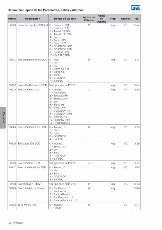
P0220 Selección Fuente LOC/REM 0 = Siempre LOC1 = Siempre REM2 = Tecla LR (LOC)3 = Tecla LR (REM)4 = DIx5 = Serial LOC6 = Serial REM7 = CO/DN/DP LOC8 = CO/DN/DP REM9 = SoftPLC LOC10 = SoftPLC REM
2 cfg I/O 13-24
P0221 Selección Referencia LOC 0 = HMI1 = AI12 = AI23 = Suma AIs > 04 = Suma AIs5 = Serial6 = CO/DN/DP7 = SoftPLC
0 cfg I/O 13-24
P0222 Selección Referencia REM Ver opciones en P0221 1 cfg I/O 13-24
P0223 Selección Giro LOC 0 = Horario1 = Antihorario2 = Tecla SG (H)3 = Tecla SG (AH)4 = DIx5 = Serial (H)6 = Serial (AH)7 = CO/DN/DP (H)8 = CO/DN/DP (AH)9 = SoftPLC (H)10 = SoftPLC (AH)11 = Polaridad AI2
2 cfg I/O 13-25
P0224 Selección Gira/Para LOC 0 = Teclas I, O1 = DIx2 = Serial3 = CO/DN/DP4 = SoftPLC
0 cfg I/O 13-25
P0225 Selección JOG LOC 0 = Inactivo1 = Tecla JOG2 = DIx3 = Serial4 = CO/DN/DP5 = SoftPLC
1 cfg I/O 13-26
P0226 Selección Giro REM Ver opciones en P0223 4 cfg I/O 13-25
P0227 Selección Gira/Para REM 0 = Teclas I, O1 = DIx2 = Serial3 = CO/DN/DP4 = SoftPLC
1 cfg I/O 13-25
P0228 Selección JOG REM Ver opciones en P0225 2 cfg I/O 13-26
P0229 Selección Modo Parada 0 = Por Rampa1 = Por Inercia2 = Parada Rápida3 = Por Rampa Iq = 04 = Parada Rápida Iq = 0
0 cfg 13-26
P0230 Zona Muera (AIs) 0 = Inactiva1 = Activa
0 I/O 13-1

CFW700 | 35
Referencia Rápida de los Parámetros, Fallas y Alarmas
Esp
añol
Parám. Descripción Rango de Valores Ajuste de Fábrica
Ajuste del
UsuarioProp. Grupos Pag.
P0231 Función de la Señal AI1 0 = Referencia Velocidad1 = N* sin Rampa2 = Máx. Corr. Torque (Par)3 = SoftPLC4 = PTC5 = Función 1 Aplicación6 = Función 2 Aplicación7 = Función 3 Aplicación8 = Función 4 Aplicación9 = Función 5 Aplicación10 = Función 6 Aplicación11 = Función 7 Aplicación12 = Función 8 Aplicación
0 cfg I/O 13-2
P0232 Ganancia de la Entrada AI1 0,000 a 9,999 1,000 I/O 13-3
P0233 Señal de la Entrada AI1 0 = 0 a 10 V / 20 mA1 = 4 a 20 mA2 = 10 V / 20 mA a 03 = 20 a 4 mA4 = -10 a 10 V
0 cfg I/O 13-4
P0234 Offset de la Entrada AI1 -100,00 a 100,00 % 0,00 % I/O 13-3
P0235 Filtro de la Entrada AI1 0,00 a 16,00 s 0,00 s I/O 13-3
P0236 Función de la Señal AI2 Ver opciones en P0231 0 cfg I/O 13-2
P0237 Ganancia de la Entrada AI2 0,000 a 9,999 1,000 I/O 13-3
P0238 Señal de la Entrada AI2 0 = 0 a 10 V / 20 mA1 = 4 a 20 mA2 = 10 V / 20 mA a 03 = 20 a 4 mA4 = -10 a 10 V
0 cfg I/O 13-4
P0239 Offset de la Entrada AI2 -100,00 a 100,00 % 0,00 % I/O 13-3
P0240 Filtro de la Entrada AI2 0,00 a 16,00 s 0,00 s I/O 13-3
P0246 Configuración de la Entrada en Frecuencia
0 = Inactiva 1 = DI32 = DI4
0 cfg 13-23
P0251 Función de la Salida AO1 0 = Referencia Velocidad1 = Referencia Total2 = Velocidad Real3 = Ref. Corr. Torque (Par)4 = Corr. Torque (Par)5 = Corriente de Salida6 = Corriente Activa7 = Potencia de Salida8 = Corr. Torque (Par) > 09 = Torque (Par) Motor10 = SoftPLC11 = PTC12 = Ixt Motor13 = Velocidad Encoder14 = Contenido P069615 = Contenido P069716 = Corriente Id*17 = Función 1 Aplicación18 = Función 2 Aplicación19 = Función 3 Aplicación20 = Función 4 Aplicación21 = Función 5 Aplicación22 = Función 6 Aplicación23 = Función 7 Aplicación24 = Función 8 Aplicación
2 I/O 13-6
P0252 Ganancia de Salida AO1 0,000 a 9,999 1,000 I/O 13-6

36 | CFW700
Referencia Rápida de los Parámetros, Fallas y Alarmas
Esp
añol
Parám. Descripción Rango de Valores Ajuste de Fábrica
Ajuste del
UsuarioProp. Grupos Pag.
P0253 Señal de la Salida AO1 0 = 0 a 10 V / 20 mA1 = 4 a 20 mA2 = 10 V / 20 mA a 03 = 20 a 4 mA
0 cfg I/O 13-8
P0254 Función de la Salida AO2 Ver opciones en P0251 5 13-6
P0255 Ganancia de la Salida AO2 0,000 a 9,999 1,000 I/O 13-6
P0256 Señal de la Salida AO2 0 = 0 a 10 V / 20 mA1 = 4 a 20 mA2 = 10 V / 20 mA a 03 = 20 a 4 mA
0 cfg I/O 13-8
P0263 Función de la Entrada DI1 0 = Sin Función1 = Gira/Para2 = Habilita General3 = Parada Rápida4 = Sentido de Giro5 = LOC/REM6 = JOG7 = SoftPLC8 = 2ª Rampa9 = Velocidad/Torque (Par)10 = JOG +11 = JOG –12 = Sin Alarma Externa13 = Sin Falla Externa14 = Reset15 = Deshabilita FlyStart16 = Regulador Bus CC17 = Bloquea Programa18 = Carga Usuario 119 = Carga Usuario 220 = Función 1 Aplicación21 = Función 2 Aplicación22 = Función 3 Aplicación23 = Función 4 Aplicación24 = Función 5 Aplicación25 = Función 6 Aplicación26 = Función 7 Aplicación27 = Función 8 Aplicación 28 = Función 9 Aplicación29 = Función 10 Aplicación30 = Función 11 Aplicación31 = Función 12 Aplicación
1 cfg I/O 13-10
P0264 Función de la Entrada DI2 Ver opciones en P0263 4 cfg I/O 13-10
P0265 Función de la Entrada DI3 Ver opciones en P0263 0 cfg I/O 13-10
P0266 Función de la Entrada DI4 Ver opciones en P0263 0 cfg I/O 13-10
P0267 Función de la Entrada DI5 Ver opciones en P0263 6 cfg I/O 13-10
P0268 Función de la Entrada DI6 Ver opciones en P0263 8 cfg I/O 13-10
P0269 Función de la Entrada DI7 Ver opciones en P0263 0 cfg I/O 13-10
P0270 Función de la Entrada DI8 Ver opciones en P0263 0 cfg I/O 13-10

CFW700 | 37
Referencia Rápida de los Parámetros, Fallas y Alarmas
Esp
añol
Parám. Descripción Rango de Valores Ajuste de Fábrica
Ajuste del
UsuarioProp. Grupos Pag.
P0275 Función de la Salida DO1 (RL1)
0 = Sin Función1 = N* > Nx2 = N > Nx3 = N < Ny4 = N = N*5 = Velocidad Nula6 = Is > Ix7 = Is < Ix8 = Torque (Par) > Tx9 = Torque (Par) < Tx10 = Remoto11 = Run12 = Ready13 = Sin Falla14 = Sin F007015 = Sin F007116 = Sin F0006/21/2217 = Sin F005118 = Sin F007219 = 4-20 mA OK20 = Contenido P069521 = Sentido Horario22 = Ride-Through23 = Precarga OK24 = Con Falla25 = Horas Habilitado > Hx26 = SoftPLC27 = N > Nx/Nt > Nx28 = F > Fx (1)29 = F > Fx (2)30 = STO31 = Sin F016032 = Sin Alarma33 = Sin Falla/Alarma34 = Función 1 Aplicación35 = Función 2 Aplicación36 = Función 3 Aplicación37 = Función 4 Aplicación38 = Función 5 Aplicación39 = Función 6 Aplicación40 = Función 7 Aplicación41 = Función 8 Aplicación 42 = Autoajuste
13 cfg I/O 13-16
P0276 Función de la Salida DO2 Ver opciones en P0275 2 cfg I/O 13-16
P0277 Función de la Salida DO3 Ver opciones en P0275 1 cfg I/O 13-16
P0278 Función de la Salida DO4 Ver opciones en P0275 0 cfg I/O 13-16
P0279 Función de la Salida DO5 Ver opciones en P0275 0 cfg I/O 13-16
P0281 Frecuencia Fx 0,0 a 300,0 Hz 4,0 Hz 13-20
P0282 Histerese Fx 0,0 a 15,0 Hz 2,0 Hz 13-21
P0287 Histerese Nx / Ny 0 a 900 rpm 18 (15) rpm 13-21
P0288 Velocidad Nx 0 a 18000 rpm 120 (100) rpm
13-21
P0289 Velocidad Ny 0 a 18000 rpm 1800 (1500) rpm
13-21
P0290 Corriente Ix 0 a 2xInom-ND 1,0xInom-ND 13-21
P0291 Velocidad Nula 0 a 18000 rpm 18 (15) rpm 13-22
P0292 Rango para N = N* 0 a 18000 rpm 18 (15) rpm 13-22
P0293 Par (Torque) Tx 0 a 200 % 100 % 13-22

38 | CFW700
Referencia Rápida de los Parámetros, Fallas y Alarmas
Esp
añol
Parám. Descripción Rango de Valores Ajuste de Fábrica
Ajuste del
UsuarioProp. Grupos Pag.
P0294 Horas Hx 0 a 6553 h 4320 h 13-22
P0295 Corriente Nominal ND / HD del VFD
0 = 2 A / 2 A1 = 3,6 A / 3,6 A2 = 5 A / 5 A3 = 6 A / 5 A4 = 7 A / 5,5 A5 = 7 A / 7 A6 = 10 A / 8 A7 = 10 A / 10 A8 = 13 A / 11 A9 = 13,5 A / 11 A10 = 16 A / 13 A11 = 17 A / 13,5 A12 = 24 A / 19 A 13 = 24 A / 20 A14 = 28 A / 24 A15 = 31 A / 25 A16 = 33,5 A / 28 A17 = 38 A / 33 A18 = 45 A / 36 A19 = 45 A / 38 A20 = 54 A / 45 A21 = 58,5 A / 47 A22 = 70 A / 56 A23 = 70,5 A / 61 A24 = 86 A / 70 A25 = 88 A / 73 A26 = 105 A / 86 A27 = 105 A / 88 A28 = 142 A / 115 A29 = 180 A / 142 A30 = 211 A / 180 A 31 = 2,9 A / 2,7 A32 = 4,2 A / 3,8 A33 = 7 A / 6,5 A 34 = 10 A / 9 A 35 = 12 A / 10 A 36 = 17 A / 17 A 37 = 22 A / 19 A 38 = 27 A / 22 A 39 = 32 A / 27 A 40 = 44 A / 36 A 41 = 53 A / 44 A 42 = 63 A / 53 A 43 = 80 A / 66 A 44 = 107 A / 90 A 45 = 125 A / 107 A 46 = 150 A / 122 A
ro READ 6-6
P0296 Tensión Nominal de la Red 0 = 200 / 240 V1 = 380 V2 = 400 / 415 V3 = 440 / 460 V4 = 480 V 5 = 500 / 525 V 6 = 550 / 575 V 7 = 600 V
De acuerdo con el
modelo del Convertidor
de Frecuencia
cfg 6-7
P0297 Frecuencia de Conmutación
0 = 1,25 kHz1 = 2,5 kHz2 = 5,0 kHz3 = 10,0 kHz 4 = 2,0 kHz
De acuerdo con el
modelo delConvertidor
deFrecuencia
cfg 6-7

CFW700 | 39
Referencia Rápida de los Parámetros, Fallas y Alarmas
Esp
añol
Parám. Descripción Rango de Valores Ajuste de Fábrica
Ajuste del
UsuarioProp. Grupos Pag.
P0298 Aplicación 0 = Uso Normal (ND)1 = Uso Pesado (HD)
0 cfg 6-8
P0299 Tiempo Frenado – Arranque 0,0 a 15,0 s 0,0 s V/f, VVW, Sless
12-16
P0300 Tiempo Frenado – Parada 0,0 a 15,0 s 0,0 s V/f, VVW, Sless
12-16
P0301 Velocidad de Inicio 0 a 450 rpm 30 rpm V/f, VVW, Sless
12-18
P0302 Tensión Frenado CC 0,0 a 10,0 % 2,0 % V/f, VVW 12-18
P0303 Velocidad Rechazada 1 0 a 18000 rpm 600 rpm 12-19
P0304 Velocidad Rechazada 2 0 a 18000 rpm 900 rpm 12-19
P0305 Velocidad Rechazada 3 0 a 18000 rpm 1200 rpm 12-19
P0306 Rango Rechazado 0 a 750 rpm 0 rpm 12-19
P0308 Dirección Serial 1 a 247 1 NET 17-1
P0310 Tasa Comunicación Serial 0 = 9600 bits/s1 = 19200 bits/s2 = 38400 bits/s3 = 57600 bits/s
1 NET 17-1
P0311 Configuración Bytes Serial 0 = 8 bits, sin, 11 = 8 bits, par, 12 = 8 bits, impar, 13 = 8 bits, sin, 24 = 8 bits, par, 25 = 8 bits, impar, 2
1 NET 17-1
P0313 Acción para el Error de Comunicación
0 = Inactivo1 = Para por Rampa2 = Deshabilita General3 = Va para modo LOC4 = LOC y Mantenga Habil.5 = Causa Falla
1 NET 17-3
P0314 Watchdog Serial 0,0 a 999,0 s 0,0 s NET 17-1
P0316 Estado Interf. Serial 0 = Inactivo1 = Activo2 = Error Watchdog
ro NET 17-1
P0317 Start-up Orientado 0 = No1 = Sí
0 cfg STARTUP 7-2
P0318 Función Copy MemCard 0 = Inactiva1 = Conv. → MMF2 = MMF → Conv.3 = Sinc. Conv. → MMF4 = Formata MMF5 = Copiar Prog. SofPLC 6 = Salvar Prog. SoftPLC
0 cfg 7-3
P0320 FlyStart/Ride-Through 0 = Inactivas1 = FlyStar2 = FS/RT3 = Ride-Through
0 cfg 12-8
P0321 Ud para Falta de la Red 178 a 770 V 505 V Vectorial 12-14
P0322 Ud para Ride-Through 178 a 770 V 490 V Vectorial 12-14
P0323 Ud para Retorno de la Red 178 a 770 V 535 V Vectorial 12-14
P0325 Ganancia Proporcional RT 0,0 a 63,9 22,8 Vectorial 12-15
P0326 Ganancia Integral RT 0,000 a 9,999 0,128 Vectorial 12-15

40 | CFW700
Referencia Rápida de los Parámetros, Fallas y Alarmas
Esp
añol
Parám. Descripción Rango de Valores Ajuste de Fábrica
Ajuste del
UsuarioProp. Grupos Pag.
P0327 Rampa Corriente I/f – F.S. 0,000 a 1,000 s 0,070 s Sless 12-10
P0328 Filtro Flying Start 0,000 a 1,000 s 0,085 s Sless 12-10
P0329 Rampa Frecuencia I/f – F.S. 2,0 a 50,0 20,0 Sless 12-10
P0331 Rampa de Tensión 0,2 a 60,0 s 2,0 s V/f, VVW 12-12
P0332 Tiempo Muerto 0,1 a 10,0 s 1,0 s V/f, VVW 12-12
P0340 Tiempo Auto-Reset 0 a 255 s 0 s 15-8
P0343 Tiempo Auto-Reset 0 = Inactiva1 = Activa
1 cfg 15-8
P0344 Configuración Limitación Corriente
0 = Hold – LR ON1 = Desacelera – LR ON
1 cfg, V/f, VVW
9-6
P0348 Configuración Sobrecarga Motor
0 = Inactivo1 = Falla/Alarma2 = Falla3 = Alarma
1 cfg 15-8
P0349 Nivel para Alarma Ixt 70 a 100 % 85 % cfg 15-9
P0350 Configuración Sobrecarga IGBTs
0 = F c/red. Fs1 = F/A c/red. Fs2 = F s/red. Fs3 = F/A s/red. Fs
1 cfg 15-9
P0351 Configuración Sobretemperatura Motor
0 = Inactivo1 = Falla/Alarma2 = Falla3 = Alarma
1 cfg 15-10
P0352 Configuración Ventiladores 0 = VD-OFF, VI-OFF1 = VD-ON, VI-ON2 = VD-CT, VI-CT3 = VD-CT, VI-OFF4 = VD-CT, VI-ON5 = VD-ON, VI-OFF6 = VD-ON, VI-CT7 = VD-OFF, VI-ON8 = VD-OFF, VI-CT9 = VD-CT, VI-CT *10 = VD-CT, VI-OFF *11 = VD-CT, VI-ON *12 = VD-ON, VI-CT *13 = VD-OFF, VI-CT *
2 cfg 15-11
P0353 Configuración Sobretemperatura IGBT / Aire
0 = D-F/A, AR-F/A1 = D-F/A, AR-F2 = D-F, AR-F/A3 = D-F, AR-F4 = D-F/A, AR-F/A *5 = D-F/A, AR-F *6 = D-F, AR-F/A *7 = D-F, AR-F *
0 cfg 15-12
P0354 Configuración Velocidad Ventilador
0 = Inactivo1 = Falla
1 cfg 15-12
P0355 Configuración de la Falla F0185
0 = Inactiva1 = Activa
1 cfg 15-13
P0356 Compensación Tiempo Muerto
0 = Inactiva1 = Activa
1 cfg 15-13
P0357 Tiempo Falta Fase Red 0 a 60 s 3 s 15-13
P0358 Config. Falla Encoder 0 = Inactivas1 = F0067 activa2 = F0079 activa3 = F0067, F0079 activas
3 cfg, Enc 15-14

CFW700 | 41
Referencia Rápida de los Parámetros, Fallas y Alarmas
Esp
añol
Parám. Descripción Rango de Valores Ajuste de Fábrica
Ajuste del
UsuarioProp. Grupos Pag.
P0360 Histéresis de Velocidad 0,0 a 100,0 % 10,0 % Vectorial 11-24
P0361 Tiempo con Velocidad diferente de la Referencia
0,0 a 999,0 s 0,0 s Vectorial 11-24
P0372 Corriente Frenado CC (Sless)
0,0 a 90,0 % 40,0 % Sless 12-18
P0397 Compensación Deslizamiento Regeneración
0 = Inactiva1 = Activa
1 cfg, VVW
10-3
P0398 Factor Servicio del Motor 1,00 a 1,50 1,00 cfg MOTOR 11-10
P0399 Rendimiento Nominal del Motor
50,0 a 99,9 % 67,0 % cfg, VVW
MOTOR 10-3
P0400 Tensión Nominal del Motor 0 a 600 V 440 V cfg MOTOR 11-10
P0401 Corriente Nominal del Motor
0 a 1,3xInom-ND 1,0xInom-ND cfg MOTOR 11-10
P0402 Rotación Nominal del Motor
0 a 18000 rpm 1750 (1458) rpm
cfg MOTOR 11-11
P0403 Frecuencia Nominal del Motor
0 a 300 Hz 60 (50) Hz cfg MOTOR 11-11
P0404 Potencia Nominal del Motor
0 = 0,33 CV1 = 0,50 CV2 = 0,75 CV3 = 1,0 CV4 = 1,5 CV5 = 2,0 CV6 = 3,0 CV7 = 4,0 CV8 = 5,0 CV9 = 5,5 CV10 = 6,0 CV11 = 7,5 CV12 = 10,0 CV13 = 12,5 CV14 = 15,0 CV15 = 20,0 CV16 = 25,0 CV17 = 30,0 CV18 = 40,0 CV19 = 50,0 CV20 = 60,0 CV21 = 75,0 CV22 = 100,0 CV23 = 125,0 CV24 = 150,0 CV25 = 175,0 CV
Motormax-ND cfg MOTOR 11-11
P0405 Numero de Pulsos del Encoder
100 a 9999 ppr 1024 ppr cfg MOTOR 11-12
P0406 Ventilación del Motor 0 = Autoventilado1 = Independente2 = Fluxo Ótimo3 = Protección Extendida
0 cfg MOTOR 11-12
P0407 Factor Potencia Nominal Motor
0,50 a 0,99 0,68 cfg, VVW MOTOR 9-12
P0408 Ejecutar Autoajuste 0 = No1 = Sin Girar2 = Girar para Im3 = Girar para Tm
4 = Estimar Tm
0 cfg, V VW,
Vectorial
MOTOR 11-19

42 | CFW700
Referencia Rápida de los Parámetros, Fallas y Alarmas
Esp
añol
Parám. Descripción Rango de Valores Ajuste de Fábrica
Ajuste del
UsuarioProp. Grupos Pag.
P0409 Resistencia del Estator 0,000 a 9,999 ohm 0,000 ohm cfg, VVW, Vectorial
MOTOR 11-20
P0410 Corriente de Magnetización
0 a 1,25xInom-ND Inom-ND MOTOR 11-21
P0411 Inductancia de Dispersión 0,00 a 99,99 mH 0,00 mH cfg, Vectorial
MOTOR 11-21
P0412 Constante Tr 0,000 a 9,999 s 0,000 s Vectorial MOTOR 11-21
P0413 Constante Tm 0,00 a 99,99 s 0,00 s Vectorial MOTOR 11-22
P0510 Unidad Ing. Ind. 1 0 = Ninguna1 = V2 = A3 = rpm4 = s5 = ms6 = N7 = m8 = Nm9 = mA10 = %11 = °C12 = CV13 = Hz14 = HP15 = h16 = W17 = kW18 = kWh19 = H
HMI 5-6
P0511 Forma Indicación Ind. 1 0 = wxyz1 = wxy.z2 = wx.yz3 = w.xyz
1 HMI 5-6
P0512 Unidad Ing. Ind. 2 Ver opciones en P0510 3 HMI 5-7
P0513 Forma Indicación Ind. 2 0 = wxyz1 = wxy.z2 = wx.yz3 = w.xyz
0 HMI 5-7
P0514 Unidad Ing. Ind. 3 Ver opciones en P0510 0 HMI 5-8
P0515 Forma Indicación Ind. 3 0 = wxyz1 = wxy.z2 = wx.yz3 = w.xyz
0 HMI 5-8
P0516 Unidad Ing. Ind. 4 Ver opciones en P0510 0 HMI 5-9
P0517 Forma Indicación Ind. 4 0 = wxyz1 = wxy.z2 = wx.yz3 = w.xyz
0 HMI 5-9
P0588 Nivel de Máximo Torque 0 a 85 % 0 % cfg, V/f 9-12
P0589 Nivel de Mínima Tensión Aplicada
40 a 80 % 40 % cfg, V/f 9-12
P0590 Nivel de Mínima Velocidad 0 a 18000 rpm 600 (525) rpm
cfg, V/f 9-13
P0591 Histéresis para el Nivel Máximo de torque
0 a 30 % 10 % cfg, V/f 9-13

CFW700 | 43
Referencia Rápida de los Parámetros, Fallas y Alarmas
Esp
añol
Parám. Descripción Rango de Valores Ajuste de Fábrica
Ajuste del
UsuarioProp. Grupos Pag.
P0680 Estado Lógico Bit 0 = Reservado Bit 1 = Comando Gira Bit 2 = Reservado Bit 3 = Reservado Bit 4 = En Parada Rápida Bit 5 = 2ª RampaBit 6 = Modo ConfiguraciónBit 7 = AlarmaBit 8 = Eje GirandoBit 9 = HabilitadoBit 10 = HorarioBit 11 = JOGBit 12 = RemotoBit 13 = SubtensiónBit 14 = ReservadoBit 15 = Falla
ro NET 17-3
P0681 Velocidad 13 Bits -32768 a 32767 ro NET 17-3
P0682 Control Serial Bit 0 = Habilita RampaBit 1 = Habilita GeneralBit 2 = Girar HorarioBit 3 = Habilita JOGBit 4 = RemotoBit 5 = 2ª RampaBit 6 = ReservadoBit 7 = Reset de FallaBit 8 a 15 = Reservado
ro NET 17-1
P0683 Referencia Velocidad Serial
-32768 a 32767 ro NET 17-1
P0684 Control CO/DN/DP Ver opciones en P0682 ro NET 17-1
P0685 Referencia Velocidad CO/DN/DP
-32768 a 32767 ro NET 17-1
P0695 Valor para DOx Bit 0 = DO1Bit 1 = DO2Bit 2 = DO3Bit 3 = DO4Bit 4 = DO5
Bit 4 NET 17-3
P0696 Valor 1 para AOx -32768 a 32767 0 NET 17-3
P0697 Valor 2 para AOx -32768 a 32767 0 NET 17-3
P0700 Protocolo CAN 1 = CANopen2 = DeviceNet
2 NET 17-1
P0701 Dirección CAN 0 a 127 63 NET 17-1
P0702 Tasa de Comunicación CAN
0 = 1 Mbps/Auto1 = Reservado/Auto2 = 500 Kbps3 = 250 Kbps4 = 125 Kbps5 = 100 Kbps/Auto6 = 50 Kbps/Auto7 = 20 Kbps/Auto8 = 10 Kbps/Auto
0 NET 17-1
P0703 Reset de Bus Off 0 = Manual1 = Automático
1 NET 17-1
P0705 Estado Controlador CAN 0 = Inactivo1 = Auto-baud2 = CAN Activo3 = Warning4 = Error Pasivo5 = Bus Off6 = No Alimentado
ro NET 17-1

44 | CFW700
Referencia Rápida de los Parámetros, Fallas y Alarmas
Esp
añol
Parám. Descripción Rango de Valores Ajuste de Fábrica
Ajuste del
UsuarioProp. Grupos Pag.
P0706 Telegrama CAN RX 0 a 65535 ro NET 17-1
P0707 Telegrama CAN TX 0 a 65535 ro NET 17-1
P0708 Contador de Bus Off 0 a 65535 ro NET 17-1
P0709 Mensajes CAN Perdidos 0 a 65535 ro NET 17-1
P0710 Instancias I/O DNet 0 = ODVA Basic 2W1 = ODVA Extend 2W2 = Especif. Fab. 2W3 = Especif. Fab. 3W4 = Especif. Fab. 4W5 = Especif. Fab. 5W6 = Especif. Fab. 6W
0 NET 17-1
P0711 Lectura #3 DeviceNet 0 a 1199 0 NET 17-2
P0712 Lectura #4 DeviceNet 0 a 1199 0 NET 17-2
P0713 Lectura #5 DeviceNet 0 a 1199 0 NET 17-2
P0714 Lectura #6 DeviceNet 0 a 1199 0 NET 17-2
P0715 Escritura #3 DeviceNet 0 a 1199 0 NET 17-2
P0716 Escritura #4 DeviceNet 0 a 1199 0 NET 17-2
P0717 Escritura #5 DeviceNet 0 a 1199 0 NET 17-2
P0718 Escritura #6 DeviceNet 0 a 1199 0 NET 17-2
P0719 Estado de la Red DeviceNet
0 = Offline1 = OnLine, No Conectado2 = OnLine, Conectado3 = Conexión Caduco4 = Falla de Conexión5 = Auto-Baud
ro NET 17-2
P0720 Estado del Maestro DNet 0 = Run1 = Idle
ro NET 17-2
P0721 Estado Comunicación CANopen
0 = Inactivo1 = Reservado2 = Comunic. Habilitada3 = Control Errores Habilit.4 = Error Guarding5 = Error Heartbeat
ro NET 17-2
P0722 Estado Nudo CANopen 0 = Inactivo1 = Inicialización2 = Parado3 = Operacional4 = Preoperacional
ro NET 17-2
P0740 Estado Comunicación Profibus
0 = Inactivo1 = Error de Acceso2 = Offline3 = Error de Configuración4 = Error de Parámetro5 = Modo Clear6 = Online
ro NET 17-2
P0741 Perfil Datos Profibus 0 = PROFIdrive1 = Fabricante
1 NET 17-2
P0742 Lectura #3 Profibus 0 a 1199 0 NET 17-2
P0743 Lectura #4 Profibus 0 a 1199 0 NET 17-2
P0744 Lectura #5 Profibus 0 a 1199 0 NET 17-2
P0745 Lectura #6 Profibus 0 a 1199 0 NET 17-2
P0746 Lectura #7 Profibus 0 a 1199 0 NET 17-2
P0747 Lectura #8 Profibus 0 a 1199 0 NET 17-2

CFW700 | 45
Referencia Rápida de los Parámetros, Fallas y Alarmas
Esp
añol
Parám. Descripción Rango de Valores Ajuste de Fábrica
Ajuste del
UsuarioProp. Grupos Pag.
P0748 Lectura #9 Profibus 0 a 1199 0 NET 17-2
P0749 Lectura #10 Profibus 0 a 1199 0 NET 17-2
P0750 Escritura #3 Profibus 0 a 1199 0 NET 17-3
P0751 Escritura #4 Profibus 0 a 1199 0 NET 17-3
P0752 Escritura #5 Profibus 0 a 1199 0 NET 17-3
P0753 Escritura #6 Profibus 0 a 1199 0 NET 17-3
P0754 Escritura #7 Profibus 0 a 1199 0 NET 17-3
P0755 Escritura #8 Profibus 0 a 1199 0 NET 17-3
P0756 Escritura #9 Profibus 0 a 1199 0 NET 17-3
P0757 Escritura #10 Profibus 0 a 1199 0 NET 17-3
P0918 Dirección Profibus 1 a 126 1 NET 17-3
P0922 Selección Telegrama Profibus
1 = Telegrama Estándar 12 = Telegrama 1003 = Telegrama 1014 = Telegrama 1025 = Telegrama 1036 = Telegrama 1047 = Telegrama 1058 = Telegrama 1069 = Telegrama 107
1 NET 17-3
P0944 Contador de Fallas 0 a 65535 ro NET 17-3
P0947 Numero de Falla 0 a 65535 ro NET 17-3
P0963 Tasa de Comunicación Profibus
0 = 9,6 kbit/s1 = 19,2 kbit/s2 = 93,75 kbit/s3 = 187,5 kbit/s4 = 500 kbit/s5 = No Detectada6 = 1500 kbit/s7 = 3000 kbit/s8 = 6000 kbit/s9 = 12000 kbit/s10 = Reservado11 = 45,45 kbit/s
ro NET 17-3
P0964 Identificación del Drive 0 a 65535 ro NET 17-3
P0965 Identificación Perfil 0 a 65535 ro NET 17-3
P0967 Palabra de Control Profidrive
0000h a FFFFh 0000h ro NET 17-3
P0968 Palabra de Estado Profidrive
0000h a FFFFh 0000h ro NET 17-3
P1000 Estado de la SoftPLC 0 = Sin Aplicativo1 = Instalando Aplicativo2 = Aplicativo Incompleto3 = Aplicativo Parado4 = Aplicativo Ejecutando
ro SPLC, READ
18-1
P1001 Comando para SoftPLC 0 = Para Aplicativo1 = Ejecuta Aplicativo2 = Excluye Aplicación
0 SPLC 18-1
P1002 Tiempo Ciclo de Scan 0,0 a 999,9 ms ro SPLC, READ
18-1

46 | CFW700
Referencia Rápida de los Parámetros, Fallas y Alarmas
Esp
añol
Parám. Descripción Rango de Valores Ajuste de Fábrica
Ajuste del
UsuarioProp. Grupos Pag.
P1003 Selección Aplicación SoftPLC
0 = Usuario1 = PID2 = P.E.3 = Multispeed4 = Start/Stop5 = Avance/Retorno 6 = Funciones Especiales de uso combinado
0 cfg SPLC 18-2
P1008 Error de Lag -9999 a 9999 ro, Enc SPLC 18-2
P1009 Ganancia de Posición 0 a 9999 10 Enc SPLC 18-3
P1010 Parámetro SoftPLC 1 -32768 a 32767 0 cfg SPLC 18-3
P1011 Parámetro SoftPLC 2 -32768 a 32767 0 cfg SPLC 18-3
P1012 Parámetro SoftPLC 3 -32768 a 32767 0 cfg SPLC 18-3
P1013 Parámetro SoftPLC 4 -32768 a 32767 0 cfg SPLC 18-3
P1014 Parámetro SoftPLC 5 -32768 a 32767 0 cfg SPLC 18-3
P1015 Parámetro SoftPLC 6 -32768 a 32767 0 cfg SPLC 18-3
P1016 Parámetro SoftPLC 7 -32768 a 32767 0 cfg SPLC 18-3
P1017 Parámetro SoftPLC 8 -32768 a 32767 0 cfg SPLC 18-3
P1018 Parámetro SoftPLC 9 -32768 a 32767 0 cfg SPLC 18-3
P1019 Parámetro SoftPLC 10 -32768 a 32767 0 cfg SPLC 18-3
P1020 Parámetro SoftPLC 11 -32768 a 32767 0 cfg SPLC 18-3
P1021 Parámetro SoftPLC 12 -32768 a 32767 0 cfg SPLC 18-3
P1022 Parámetro SoftPLC 13 -32768 a 32767 0 cfg SPLC 18-3
P1023 Parámetro SoftPLC 14 -32768 a 32767 0 cfg SPLC 18-3
P1024 Parámetro SoftPLC 15 -32768 a 32767 0 cfg SPLC 18-3
P1025 Parámetro SoftPLC 16 -32768 a 32767 0 cfg SPLC 18-3
P1026 Parámetro SoftPLC 17 -32768 a 32767 0 cfg SPLC 18-3
P1027 Parámetro SoftPLC 18 -32768 a 32767 0 cfg SPLC 18-3
P1028 Parámetro SoftPLC 19 -32768 a 32767 0 cfg SPLC 18-3
P1029 Parámetro SoftPLC 20 -32768 a 32767 0 cfg SPLC 18-3
P1030 Parámetro SoftPLC 21 -32768 a 32767 0 cfg SPLC 18-3
P1031 Parámetro SoftPLC 22 -32768 a 32767 0 cfg SPLC 18-3
P1032 Parámetro SoftPLC 23 -32768 a 32767 0 cfg SPLC 18-3
P1033 Parámetro SoftPLC 24 -32768 a 32767 0 cfg SPLC 18-3
P1034 Parámetro SoftPLC 25 -32768 a 32767 0 cfg SPLC 18-3
P1035 Parámetro SoftPLC 26 -32768 a 32767 0 cfg SPLC 18-3
P1036 Parámetro SoftPLC 27 -32768 a 32767 0 cfg SPLC 18-3
P1037 Parámetro SoftPLC 28 -32768 a 32767 0 cfg SPLC 18-3
P1038 Parámetro SoftPLC 29 -32768 a 32767 0 cfg SPLC 18-3
P1039 Parámetro SoftPLC 30 -32768 a 32767 0 cfg SPLC 18-3
P1040 Parámetro SoftPLC 31 -32768 a 32767 0 cfg SPLC 18-3
P1041 Parámetro SoftPLC 32 -32768 a 32767 0 cfg SPLC 18-3
P1042 Parámetro SoftPLC 33 -32768 a 32767 0 cfg SPLC 18-3
P1043 Parámetro SoftPLC 34 -32768 a 32767 0 cfg SPLC 18-3
P1044 Parámetro SoftPLC 35 -32768 a 32767 0 cfg SPLC 18-3
P1045 Parámetro SoftPLC 36 -32768 a 32767 0 cfg SPLC 18-3
P1046 Parámetro SoftPLC 37 -32768 a 32767 0 cfg SPLC 18-3

CFW700 | 47
Referencia Rápida de los Parámetros, Fallas y Alarmas
Esp
añol
Parám. Descripción Rango de Valores Ajuste de Fábrica
Ajuste del
UsuarioProp. Grupos Pag.
P1047 Parámetro SoftPLC 38 -32768 a 32767 0 cfg SPLC 18-3
P1048 Parámetro SoftPLC 39 -32768 a 32767 0 cfg SPLC 18-3
P1049 Parámetro SoftPLC 40 -32768 a 32767 0 cfg SPLC 18-3
P1050 Parámetro SoftPLC 41 -32768 a 32767 0 cfg SPLC 18-3
P1051 Parámetro SoftPLC 42 -32768 a 32767 0 cfg SPLC 18-3
P1052 Parámetro SoftPLC 43 -32768 a 32767 0 cfg SPLC 18-3
P1053 Parámetro SoftPLC 44 -32768 a 32767 0 cfg SPLC 18-3
P1054 Parámetro SoftPLC 45 -32768 a 32767 0 cfg SPLC 18-3
P1055 Parámetro SoftPLC 46 -32768 a 32767 0 cfg SPLC 18-3
P1056 Parámetro SoftPLC 47 -32768 a 32767 0 cfg SPLC 18-3
P1057 Parámetro SoftPLC 48 -32768 a 32767 0 cfg SPLC 18-3
P1058 Parámetro SoftPLC 49 -32768 a 32767 0 cfg SPLC 18-3
P1059 Parámetro SoftPLC 50 -32768 a 32767 0 cfg SPLC 18-3
¡Notas!ro = Parámetro solamente de lectura.rw = Parámetro de lectura/escrita.cfg = Parámetro de configuración, solamente puede ser cambiado con el motor parado.V/f = Parámetro disponible en modo V/f.Adj = Parámetro disponible solo en V/f ajustable.VVW = Parámetro disponible en modo VVW.Vectorial = Parámetro disponible en el modo vectorial.Sless = Parámetro disponible solo en modo sensorless.Enc = Parámetro disponible solo en modo vectorial con encoder.

48 | CFW700
Referencia Rápida de los Parámetros, Fallas y Alarmas
Esp
añol
Falla/Alarma Descripción Causa Más Probable
F0006:Desequilibrio Falta de Fase en la Red
Falla de desequilibrio o falta de fase en la red de alimentación.Observación: - Caso el motor no tenga carga en el eje o se encuentra con baja carga podrá no ocurrir esta falla.- Tiempo de actuación ajustado en P0357. P0357 = 0 deshabilita la falla.
Falta de fase en la entrada de convertidor de frecuencia.
Desequilibrio de tensión de entrada > 5 %.
F0021:Subtensión Bus CC
Falla de subtensión en el circuito intermediario.
Tensión de alimentación muy baja, ocasionando tensión en el bus CC menos que el valor mínimo (leer el valor en el parámetro P0004):Ud < 223 V - Tensión de alimentación trifásica 200 / 240 V.Ud < 170 V - Tensión de alimentación monofásica 200 / 240 V (modelos CFW700XXXXS2 o CFW700XXXXB2) (P0296 = 0).Ud < 385 V - Tensión de alimentación 380 V (P0296 = 1).Ud < 405 V - Tensión de alimentación 400 / 415 V (P0296 = 2).Ud < 446 V - Tensión de alimentación 440 / 460 V (P0296 = 3).Ud < 487 V - Tensión de alimentación 480 V (P0296 = 4). Ud < 530 V - Tensión de alimentación 500 / 525 V (P0296 = 5). Ud < 580 V - Tensión de alimentación 550 / 575 V (P0296 = 6). Ud < 605 V - Tensión de alimentación 600 V (P0296 = 7).
Falta de fase en la entrada. Falla en el circuito de precarga. Parámetro P0296 seleccionado para usar arriba de la tensión nominal de la red.
F0022:Sobretensión Bus CC
Falla de sobretensión el circuito intermediario.
Tensión de alimentación muy alta, resultando en una tensión el en bus CC arriba del valor máximo:Ud > 400 V - Modelos 220 / 230 Vca (P0296 = 0).Ud > 800 V - Modelos 380 / 480 Vca (P0296 = 1, 2, 3 o 4). Ud > 1000 V - Modelos 500 / 600 V (P0296 = 5, 6 o 7).
Inercia de carga accionada muy alta o rampa de desaceleración muy rápida.
Ajuste de P0151 o P0153 o P0185 muy alto.A0046:Sobretensión en el Bus CC
Alarma de sobrecarga en el motor.Observación: Puede ser deshabilitada ajustando P0348 = 0 o 2.
Ajuste de P0156, P0157 y P0158 bajo para el motor utilizado.
Carga en el eje del motor muy alta.
A0047:Carga Alta en los IGBTs
Alarma de sobrecarga en los IGBTs.Observación: Puede ser deshabilitada ajustando P0350 = 0 o 2.
Corriente alta en la salida del convertidor de frecuencia.
F0048: Sobrecarga en los IGBTs
Falla de sobrecarga en los IGBTs. Corriente muy alta en la salida del convertidor de frecuencia.
A0050:Temperatura IGBTs Alta
Alarma de temperatura elevada medida en los sensores de temperatura (NTC) de los IGBTs.Observación: Puede ser deshabilitada ajustando P0353 = 2 o 3.
Temperatura ambiente alrededor del convertidor de frecuencia alta (>50 °C) y corriente de salida elevada.
Ventilador bloqueado o con defecto. Disipador muy sucio.
F0051:Sobretemperatura IGBTs
Falla de sobretemperatura elevada medida en los sensores de temperatura (NTC) de los IGBTs.

CFW700 | 49
Referencia Rápida de los Parámetros, Fallas y Alarmas
Esp
añol
Falla/Alarma Descripción Causa Más Probable
F0067:Cableado Encoder / Motor Invertido
Falla debido a relación de fase de las señales del encoder, si P0202 = 5 y P0408 = 2, 3 o 4.Observación: - No es posible hacer el reset de esta falla, si P0408 > 1.- En este caso desenergizar el convertidor de frecuencia, solucionar el problema y entonces reenergizar el equipo.- Si P0408 = 0, es posible hacer el reset de esta falla. La falla puede ser deshabilitada a través del parámetro P0358.
Cableado U, V, W para el motor invertido. Canales A y B del encoder invertidos. Error en la posición del montaje del encoder.
F0070:Sobrecorriente / Cortocircuito
Sobrecorriente o cortocircuito en la salida, bus CC o resistor de frenado.
Cortocircuito entre dos fases del motor. Cortocircuito de los cables de conexión del resistor de frenado reostático.
Módulos de IGBT en cortocircuito. F0071:Sobrecorriente en la Salida
Falla de sobrecorriente en la salida. Inercia de la carga muy alta o rampa de aceleración muy rápida.
Ajuste de P0135 o P0169 y P0170 muy alto.F0072:Sobrecarga en el Motor
Falla de sobrecarga en el motor.Observación: Puede ser deshabilitado ajustando P0348 = 0 o 3.
Ajuste de P0156 o P0157 y P0158 muy bajo para el motor.
Carga en el eje del motor muy alta.
F0074:Falta a la Tierra
Falla de sobrecorriente para la tierra.Observación: Puede ser deshabilitado ajustando P0343 = 0.
Cortocircuito para el tierra en una o más fases de salida;
Capacitancia de los cables del motor elevada, lo que ocasiona picos de corrientes en la salida. (1)
F0078:Sobretemperatura Motor
Falla relacionado al sensor de temperatura tipo PTC instalado en el motor.Observación:- Puede ser deshabilitado ajustando P0351 = 0 o 3.- Necesario programar la entrada y salida analógica para función PTC.
Carga en el eje del motor muy alta. Ciclo de carga muy elevado (grande números de arranques y paradas por minuto).
Temperatura ambiente alta alrededor del convertidor de frecuencia.
Mal contacto o cortocircuito (resistencia < 100 Ω) en el cableado de conexión al termistor del motor.
Termistor del motor no instalado. Eje del motor trabado.
F0079: Falla Señales Encoder
Falla de ausencia de las señales del encoder.Observación:Detección hecha solamente por software. La falla puede ser deshabilitada a través del parámetro P0358.
Cableado entre encoder y el accesorio de interfaz para encoder interrumpido.
Encoder con defecto.
F0080:Falla en la CPU(Watchdog)
Falla de watchdog en el microcontrolador. Ruido eléctrico.
F0084:Falla de Autodiagnosis
Falla de Autodiagnosis. Defecto en los circuitos internos del convertidor de frecuencia.
A0090:Alarma Externo
Alarma externo vía DIx.Observación: Necesario programar DIx para “sin alarma externo”.
Cableado en las entrada DI1 a DI8 abier tos (programadas para “s/Alarma Ext.”).
F0091:Falla Externo
Falo externo vía DIx.Observación: Necesario programar DIx para “sin falla externo”.
Cableado en las entrada DI1 a DI8 abier tos (programadas para “s/Falla Ext.”).
A0098:Activa Habilita General
Falta del habilita general durante el autoajuste.
Cableado en la entrada DIx (programada para “Habilita General”) abierto.
F0099:Offset Corriente Inválido
Circuito de medición de corriente presenta un valor fuera del normal en la condición de corriente nula.
Defecto en los circuitos internos del convertidor de frecuencia.

50 | CFW700
Referencia Rápida de los Parámetros, Fallas y Alarmas
Esp
añol
Falla/Alarma Descripción Causa Más Probable
A0110:Temperatura Motor Alta
Alarma proveniente del sensor de temperatura tipo PTC instalado en el motor.Observación:- Puede ser deshabilitada ajustando P0351 = 0 o 2.- Necesario programar la entrada y la salida analógica para función PTC.
Carga en el eje del motor alta. Ciclo de carga elevado (gran número de arranques y paradas por minuto).
Temperatura ambiente alta alrededor del convertidor de frecuencia.
Mal contacto o cortocircuito (resistencia < 100 Ω) en el cableado conectado al termistor del motor.
Termistor del motor no instalado. Eje del motor trabado.
A0128:Timeout Comunicación Serial
Señaliza que el convertidor de frecuencia ha parado de recibir telegramas validos dentro de un determinado periodo de tiempo.Observación: Puede ser deshabilitado ajustando P0314 = 0,0 s.
Verificar la instalación de los cables de puesta a tierra.
Certifíquese de que el maestro envió un nuevo telegrama en un tiempo inferior al programa en el P0314.
A0133:Sin Alimentación CAN
Alarma de falta de alimentación en el Controlador CAN.
Cable partido o desconectado. Fuente de alimentación apagada.
A0134:Bus Off
Periférico CAN del convertidor de frecuencia fue para el estado de bus off.
Tasa de comunicación incorrecta. Dos esclavos en la red con misma dirección. Error en e l montaje de los cables (señales cambiados).
A0135:Error Comunicación CANopen
Alarma que indica error de comunicación. Problemas en la comunicación. Programación incorrecta del maestro. Conf iguración incorrecta de los objetos de comunicación.
A0136:Maestro en Idle
Maestro de la red fue para el estado ocioso (idle).
Llave del PLC en la posición ODLE. Bit del registrador de comendo del PLC en cero (0).
A0137:Timeout Conexión DeviceNet
Alarma de timeout en las conexiones I/O del DeviceNet.
Una o más conexiones del tipo I/O alocadas fueran para el estado de timeout.
A0138: (2)
Interfaz Profibus DP Modo Clear
Señaliza que el convertidor de frecuencia ha recibido el comando del maestro de la red Profibus DP para entrar en el modo Clear.
Verificar el estado del maestro de la red, certificando que este se encuentra en el modo de ejecución (RUN).
Para más informaciones consultar el manual de la comunicación Profibus DP.
A0139: (2)
Interfaz Profibus DP Offline
Señaliza interrupción en la comunicación entre el maestro de la red Profibus DP y el convertidor de frecuencia.
Verificar si el maestro de la red está configurado correctamente y operando normalmente.
Verificar la instalación de la red de manera general – pasado de los cables, puesta a tierra.
Para más informaciones consultar el manual de la comunicación Profibus DP.
A0140: (2)
Error de Acceso al Módulo Profibus DP
Señaliza error en el acceso a los datos del módulo de comunicación Profibus DP.
Verificar si el módulo Profibus DP está correctamente encajado en el slot 3.
Para más informaciones consultar en manual de la comunicación Profibus DP.
F0150:Sobrevelocidad Motor
Falla de sobrevelocidad.Activada cuando la velocidad real
P0134 x (100 % + P0132)
100 % ultrapasar el valor
de pos más de 20 ms.
Ajuste incorrecto de P0161 y/o P0162. Carga tipo grúa disparada.
F00151:Falla Módulo Memoria FLASH
Falla en el Módulo Memoria FLASH (MMF-01).
Defecto en el módulo de memoria FLASH. Módulo de memoria FLASH no está bien encajado.
A0152:Temperatura Aire Interno Alta
Alarma de temperatura del aire interno alta.Observación: Puede ser deshabilitada ajustando P0353 = 1 o 3.
Temperatura ambiente alrededor del convertidor de frecuencia alta (>50 °C) y corriente de salida elevada.
Ventilador interno con defecto (cuando existir). Temperatura en el interior el armario alta (>45 °C).
F0153:Sobretemperatura Aire Interno
Falla de sobretemperatura del aire interno. Temperatura ambiente alrededor del convertidor de frecuencia alta (>50 °C) y corriente de salida elevada.
Ventilador interno con defecto (cuando existir).
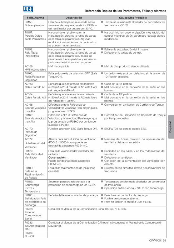
CFW700 | 51
Referencia Rápida de los Parámetros, Fallas y Alarmas
Esp
añol
Falla/Alarma Descripción Causa Más Probable
F0156:Subtemperatura
Falla de subtemperatura medida en los sensores de temperatura de los IGBTs o del rectificador por debajo de -30 °C.
Temperatura ambiente alrededor del convertidor de frecuencia ≤ -30 °C.
F0157:Perdida Datos Tabla Parámetros
Ha ocurrido un problema en la inicialización, durante la rutina de carga de la tabla de parámetros. Algunas modificaciones recientes de parámetros se pueden haber perdidas.
Ha ocurrido un desenergización muy rápido del control mientras algún parámetro estaca siendo modificado.
F0158:Falla Tabla Parámetros
Ha ocurrido un problema en la inicialización, durante la rutina de carga de la tabla de parámetros. Todos los parámetros fueran pedidos y los valores padrones de fabricas son cargados.
Falla en la actualización del firmware. Defecto en la tarjeta de control.
A0159:HMI incompatible
HMI incompatible. HMI de otro producto siendo utilizada.
F0160:Relés Parada de Seguridad
Falla en los relés de la función STO (Safe Torque Off).
Un de los relés está con defecto o sin la tensión de +24 Vcc en la bobina.
A0163:Cable Partido AI1
Señaliza que la referencia en corriente (4-20 mA o 20-4 mA) de la AI1 está fuera del rango de 4-20 mA.
Cable de la AI1 partido. Mal contacto en la conexión de la señal en los bornes.
A0164:Cable Partido AI2
Señaliza que la referencia en corriente (4-20 mA o 20-4 mA) de la AI2 está fuera del rango de 4-20 mA.
Cable de la AI2 partido. Mal contacto en la conexión de la señal en los bornes.
A0168:Error de Velocidad muy Alta
Diferencia entre la Referencia de Velocidad y la Velocidad Real mayor que la programada en P0360.
Convertidor en Limitación de Corriente de Torque.
F0169:Error de Velocidad muy Alta
Diferencia entre la Referencia de Velocidad y la Velocidad Real mayor que la programada en P0360 por un tiempo superior a P0361.
Convertidor en Limitación de Corriente de Torque por tiempo excesivo.
A0170:Parada de Seguridad
Función la función STO (Safe Torque Off). El CFW700 fue para el estado STO.
A0177:
Substituición del
Ventilador
Alarma para substituición del ventilador (P0045 > 5000 horas) puede ser deshabilita ajustando P0354 = 0.
Número de horas máximo de operación del ventilador disipador excedido.
F0179:Falla Velocidad Ventilador
Falla en la velocidad del ventilador del radiador.Observación: Puede ser deshabilitado ajustando P0354 = 0.
Suciedad en las palas y en los rodamientos del ventilador.
Defecto en el ventilador. Conexión de la alimentación del ventilador con defecto.
F0182:Falla en la Realimentación de Pulsos
Falla en la realimentación de los pulsos de salida.
Defecto en los circuitos interno del convertidor de frecuencia.
F0183:Sobrecarga IGBTs + Temperatura
Sobretemperatura relacionada a la protección de sobrecarga en los IGBTs.
Temperatura ambiente alta alrededor del convertidor de frecuencia.
Operación en frecuencia < 10 Hz con sobrecarga.
F0185:Señalización Falla en el contacto de precarga
Señaliza falla en el contactor de precarga. Defecto en el contactor de precarga. Fusible de comando abierto. Falta de fase en la entrada L1/R o L2/S.
F0228:Timeout Comunicación Serial
Consultar el Manual de la Comunicación Serial RS-232 / RS-485.
F0233:Sin Alimentación CAN
Consultar el Manual de la Comunicación CANopen y/o consultar el Manual de la Comunicación DeviceNet.
F0234:Bus Off

52 | CFW700
Referencia Rápida de los Parámetros, Fallas y Alarmas
Esp
añol
Falla/Alarma Descripción Causa Más Probable
F0235:Error Comunicación CANopen
Consultar el Manual de la Comunicación CANopen.
F0236:Maestro en Idle
Consultar el Manual de la Comunicación DeviceNet.
F0237:Timeout Conexión DeviceNetF0238: (2)
Profibus Modo Clear
Señaliza que el convertidor de frecuencia ha recibido el comando del maestro de la red Profibus DP para entrar en modo Clear.
Verif icar el estado del maestro de la red, si certificando que este se encuentra en el modo de ejecución (RUN).
La señalización del falla ocurrirá si P0313 = 5. Para más informaciones consultar el manual de la comunicación Profibus DP.
F0239: (2)
Profibus OfflineSeñaliza interrupción en la comunicación entre el maestro de la red Profibus DP y el convertidor de frecuencia.
Verificar si el maestro de la red está configurado correctamente y operando normalmente.
Verificar la instalación de la red de manera general – disposición de los cables, puesta a tierra.
La señalización del falla ocurrirá si P0313 = 5. Para más informaciones consultar el manual de la comunicación Profibus DP.
F0240: (2)
Error Acceso Interfaz Profibus DP
Señaliza error en el acceso a los datos del módulo de comunicación Profibus DP.
Verificar si el módulo Profibus DP está correctamente encajado en el slot 3.
La señalización del falla ocurrirá si P0313 = 5. Para más informaciones consultar en manual de la comunicación Profibus DP.
A0702:Convertidor de Frecuencia Deshabilitado
Consultar el Manual de la SoftPLC.
A0704:Dos Movimientos HabilitadosA0706:Referencia no Programa para SoftPLCF0711:Falla de Ejecución de la SoftPLC
Falla de ejecución de la SoftPLC. Aplicativo incompatible. Falla durante la carga del aplicativo.
Observaciones:(1) Cable de conexión entre el motor y el convertidor de frecuencia a una gran longitud. Con más de 100 metros el cable
presentará una alta capacitancia parasita para la tierra. La circulación de corriente parasita por estas capacitancias podrá provocar la activación del circuito de falta a tierra y consecuentemente el bloqueo por F0074, inmediatamente luego de la habilitación del convertidor de frecuencia.
POSIBLE SOLUCIÓN: Disminuir la frecuencia de conmutación (P0297).
(2) Con módulo Profibus DP conectado en el slot 3 (XC43).

CFW700 | 53
Referencia Rápida de los Parámetros, Fallas y Alarmas
Esp
añol
¡ATENCIÓN!Mal contacto en el cable de la HMI o ruido eléctrico en la instalación, pueden provocar el falla de comunicación de la HMI con la tarjeta de control. En esta situación la operación, por la HMI, se quedará indisponible y la siguiente señalización será presentada en el display de la HMI:


Referência Rápida dos Parâmetros, Falhas e Alarmes
Série: CFW700
Português
Documento: 10000849536 / 03
Versão de Software: 2.0X
Data: 09/2014


CFW700 | 57
Referência Rápida dos Parâmetros, Falhas e Alarmes
Português
REFERÊNCIA RÁPIDA DOS PARÂMETROS, FALHAS E ALARMES
Parâm. Descrição Faixa de ValoresAjuste
de Fábrica
Ajuste do
UsuárioPropr. Grupos Pág.
P0000 Acesso aos Parâmetros 0 a 9999 0 5-1
P0001 Referência Velocidade 0 a 18000 rpm ro READ 16-1
P0002 Velocidade do Motor 0 a 18000 rpm ro READ 16-1
P0003 Corrente do Motor 0,0 a 4500,0 A ro READ 16-1
P0004 Tensão Barram. CC (Ud) 0 a 2000 V ro READ 16-2
P0005 Frequência do Motor 0,0 a 1020,0 Hz ro READ 16-2
P0006 Estado do Inversor 0 = Ready (Pronto)1 = Run (Execução)2 = Subtensão3 = Falha4 = Autoajuste5 = Configuração6 = Frenagem CC7 = STO
ro READ 16-2
P0007 Tensão de Saída 0 a 2000 V ro READ 16-3
P0009 Torque no Motor -1000,0 a 1000,0 % ro READ 16-3
P0010 Potência de Saída 0,0 a 6553,5 kW ro READ 16-4
P0011 Cos phi da Saída 0,00 a 1,00 ro READ 16-4
P0012 Estado DI8 a DI1 Bit 0 = DI1Bit 1 = DI2Bit 2 = DI3Bit 3 = DI4Bit 4 = DI5Bit 5 = DI6Bit 6 = DI7Bit 7 = DI8
ro READ, I/O 13-9
P0013 Estado DO5 a DO1 Bit 0 = DO1Bit 1 = DO2Bit 2 = DO3Bit 3 = DO4Bit 4 = DO5
ro READ, I/O 13-14
P0014 Valor de AO1 0,00 a 100,00 % ro READ, I/O 13-5
P0015 Valor de AO2 0,00 a 100,00 % ro READ, I/O 13-5
P0018 Valor de AI1 -100,00 a 100,00 % ro READ, I/O 13-1
P0019 Valor de AI2 -100,00 a 100,00 % ro READ, I/O 13-1
P0022 Valor da Entrada em Frequência
3,0 a 6500,0 Hz ro READ 13-23
P0023 Versão de Software 0,00 a 655,35 ro READ 6-1
P0028 Config. Acessórios 0000h a FFFFh ro READ 6-2
P0029 Config. HW Potência Bit 0 a 5 = Corrente Nom.Bit 6 e 7 = Tensão Nom.Bit 8 = Filtro RFIBit 9 = Relé SegurançaBit 10 = (0)24 V/(1) Barr. CCBit 11 = Sempre 0Bit 12 = IGBT FrenagemBit 13 = EspecialBit 14 e 15 = Reservado
ro READ 6-2
P0030 Temperatura IGBTs -20,0 a 150,0 °C ro READ 15-3
P0034 Temper. Ar Interno -20,0 a 150,0 °C ro READ 15-3
P0036 Velocidade Ventilador 0 a 15000 rpm ro READ 16-5
P0037 Sobrecarga do Motor 0 a 100 % ro READ 16-5

58 | CFW700
Referência Rápida dos Parâmetros, Falhas e Alarmes
Portu
guês
Parâm. Descrição Faixa de ValoresAjuste
de Fábrica
Ajuste do
UsuárioPropr. Grupos Pág.
P0038 Velocidade do Encoder 0 a 65535 rpm ro READ 16-6
P0039 Contador Pulsos Enc. 0 a 40000 ro READ 16-6
P0042 Horas Energizado 0 a 65535 h ro READ 16-6
P0043 Horas Habilitado 0,0 a 6553,5 h ro READ 16-6
P0044 Contador kWh 0 a 65535 kWh ro READ 16-7
P0045 Horas Ventil. Ligado 0 a 65535 h ro READ 16-7
P0048 Alarme Atual 0 a 999 ro READ 16-7
P0049 Falha Atual 0 a 999 ro READ 16-7
P0050 Última Falha 0 a 999 ro READ 16-8
P0054 Segunda Falha 0 a 999 ro READ 16-8
P0058 Terceira Falha 0 a 999 ro READ 16-8
P0062 Quarta Falha 0 a 999 ro READ 16-8
P0066 Quinta Falha 0 a 999 ro READ 16-8
P0090 Corrente Últ. Falha 0,0 a 4500,0 A ro READ 16-8
P0091 Barram. CC Últ. Falha 0 a 2000 V ro READ 16-8
P0092 Velocidade Últ. Falha 0 a 18000 rpm ro READ 16-9
P0093 Referência Últ. Falha 0 a 18000 rpm ro READ 16-9
P0094 Frequência Últ. Falha 0,0 a 1020,0 Hz ro READ 16-9
P0095 Tensão Mot Últ. Falha 0 a 2000 V ro READ 16-9
P0096 Estado DIx Últ. Falha Bit 0 = DI1Bit 1 = DI2Bit 2 = DI3Bit 3 = DI4Bit 4 = DI5Bit 5 = DI6Bit 6 = DI7Bit 7 = DI8
ro READ 16-10
P0097 Estado DOx Últ. Falha Bit 0 = DO1Bit 1 = DO2Bit 2 = DO3Bit 3 = DO4Bit 4 = DO5
ro READ 16-10
P0100 Tempo Aceleração 0,0 a 999,0 s 20,0 s BASIC 12-1
P0101 Tempo Desaceleração 0,0 a 999,0 s 20,0 s BASIC 12-1
P0102 Tempo Acel. 2a Rampa 0,0 a 999,0 s 20,0 s 12-1
P0103 Tempo Desac. 2a Rampa 0,0 a 999,0 s 20,0 s 12-1
P0104 Rampa 0 = Linear1 = Curva S
0 12-2
P0105 Seleção 1a/2a Rampa 0 = 1a Rampa1 = 2a Rampa2 = DIx3 = Serial4 = CO/DN/DP5 = SoftPLC
2 cfg 12-3
P0120 Backup da Ref. Veloc. 0 = Inativa1 = Ativa
1 12-3
P0121 Referência pela HMI 0 a 18000 rpm 90 rpm 12-4
P0122 Referência JOG/JOG+ 0 a 18000 rpm 150 (125) rpm
12-4
P0123 Referência JOG- 0 a 18000 rpm 150 (125) rpm
Vetorial 12-5

CFW700 | 59
Referência Rápida dos Parâmetros, Falhas e Alarmes
Português
Parâm. Descrição Faixa de ValoresAjuste
de Fábrica
Ajuste do
UsuárioPropr. Grupos Pág.
P0132 Nível Máx. Sobrevelocidade
0 a 100 % 10 % cfg 12-5
P0133 Velocidade Mínima 0 a 18000 rpm 90 (75) rpm BASIC 12-6
P0134 Velocidade Máxima 0 a 18000 rpm 1800 (1500) rpm
BASIC 12-6
P0135 Corrente Máxima Saída 0,2 a 2xInom-HD 1,5xInom-HD V/f, VVW BASIC 9-6
P0136 Boost de Torque Man. 0 a 9 1 V/f BASIC 9-2
P0137 Boost de Torque Autom. 0,00 a 1,00 0,00 V/f 9-2
P0138 Compensação Escorreg. -10,0 a 10,0 % 0,0 % V/f 9-3
P0139 Filtro Corrente Saída 0,0 a 16,0 s 0,2 s V/f, VVW 9-4
P0142 Tensão Saída Máxima 0,0 a 100,0 % 100,0 % cfg, Adj 9-5
P0143 Tensão Saída Intermed. 0,0 a 100,0 % 50,0 % cfg, Adj 9-5
P0144 Tensão Saída em 3 Hz 0,0 a 100,0 % 8,0 % cfg, Adj 9-5
P0145 Vel. Início Enf. Campo 0 a 18000 rpm 1800 rpm cfg, Adj 9-5
P0146 Veloc. Intermediária 0 a 18000 rpm 900 rpm cfg, Adj 9-5
P0150 Tipo Regul. Ud V/f 0 = Hold Rampa1 = Acelera Rampa
0 cfg, V/f, VVW
9-10
P0151 Nível Regul. Ud V/f 339 a 1000 V 800 V V/f, VVW 9-11
P0152 Ganho Prop. Regul. Ud 0,00 a 9,99 1,50 V/f, VVW 9-11
P0153 Nível de Atuação da Frenagem Reost.
339 a 1000 V 748 V 14-1
P0156 Corr. Sobrecarga 100 % 0,1 a 1,5xInom-ND 1,05xInom-ND 15-4
P0157 Corr. Sobrecarga 50 % 0,1 a 1,5xInom-ND 0,9xInom-ND 15-4
P0158 Corr. Sobrecarga 5 % 0,1 a 1,5xInom-ND 0,65xInom-ND 15-4
P0159 Classe Térmica Motor 0 = Classe 51 = Classe 102 = Classe 153 = Classe 204 = Classe 255 = Classe 306 = Classe 357 = Classe 408 = Classe 45
1 cfg 15-5
P0160 Otimização Reg. Veloc. 0 = Normal1 = Saturado
0 cfg, Vetorial
11-13
P0161 Ganho Prop. Veloc. 0,0 a 63,9 7,4 Vetorial 11-13
P0162 Ganho Integral Veloc. 0,000 a 9,999 0,023 Vetorial 11-13
P0163 Offset Referência LOC -999 a 999 0 Vetorial 11-14
P0164 Offset Referência REM -999 a 999 0 Vetorial 11-14
P0165 Filtro de Velocidade 0,012 a 1,000 s 0,012 s Vetorial 11-14
P0166 Ganho Difer. Veloc. 0,00 a 7,99 0,00 Vetorial 11-15
P0167 Ganho Prop. Corrente 0,00 a 1,99 0,50 Vetorial 11-15
P0168 Ganho Integ. Corrente 0,000 a 1,999 0,010 Vetorial 11-15
P0169 Máx. Corrente Torque + 0,0 a 350,0 % 125,0 % Vetorial 11-22
P0170 Máx. Corrente Torque - 0,0 a 350,0 % 125,0 % Vetorial 11-22
P0175 Ganho Propor. Fluxo 0,0 a 31,9 2,0 Vetorial 11-16
P0176 Ganho Integral Fluxo 0,000 a 9,999 0,020 Vetorial 11-16
P0178 Fluxo Nominal 0 a 120 % 100 % Vetorial 11-16
P0180 Iq* após o I/f 0 a 350 % 10 % Sless 11-17

60 | CFW700
Referência Rápida dos Parâmetros, Falhas e Alarmes
Portu
guês
Parâm. Descrição Faixa de ValoresAjuste
de Fábrica
Ajuste do
UsuárioPropr. Grupos Pág.
P0182 Veloc. p/ Atuação I/f 0 a 90 rpm 18 rpm Sless 11-17
P0183 Corrente no Modo I/f 0 a 9 1 Sless 11-18
P0184 Modo Regulação Ud 0 = Com perdas1 = Sem perdas2 = Hab./Desab. DIx
1 cfg, Vetorial
11-24
P0185 Nível Regulação Ud 339 a 1000 V 800 V Vetorial 11-25
P0186 Ganho Proporcional Ud 0,0 a 63,9 26,0 Vetorial 11-25
P0187 Ganho Integral Ud 0,000 a 9,999 0,010 Vetorial 11-25
P0190 Tensão Saída Máxima 0 a 600 V 440 V Vetorial 11-17
P0191 Busca de Zero Encoder 0 = Inativa1 = Ativa
0 12-20
P0192 Estado Busca Zero Enc. 0 = Inativo1 = Concluído
0 ro READ 12-20
P0200 Senha 0 = Inativa1 = Ativa2 = Alterar senha
1 HMI 5-2
P0202 Tipo de Controle 0 = V/f 60 Hz1 = V/f 50 Hz2 = V/f Ajustável3 = VVW4 = Sensorless5 = Encoder
0 cfg 9-5
P0204 Carrega/Salva Parâm. 0 = Sem Função1 = Sem Função2 = Reset P00453 = Reset P00434 = Reset P00445 = Carrega 60 Hz6 = Carrega 50 Hz7 = Carr. Usuário 18 = Carr. Usuário 29 = Salva Usuário 110 = Salva Usuário 2
0 cfg 7-1
P0205 Seleção Parâmetro do Display Principal
0 a 1199 2 HMI 5-3
P0206 Seleção Parâmetro do Display Secundário
0 a 1199 1 HMI 5-3
P0207 Seleção Parâmetro da Barra Gráfica
0 a 1199 3 HMI 5-3
P0208 Fator de Escala do Display Principal
0,1 a 1000,0 % 100,0 % HMI 5-4
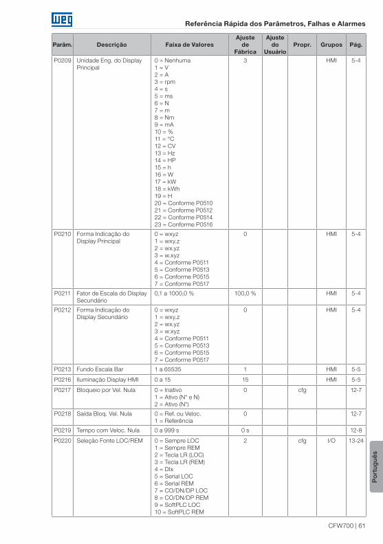
CFW700 | 61
Referência Rápida dos Parâmetros, Falhas e Alarmes
Português
Parâm. Descrição Faixa de ValoresAjuste
de Fábrica
Ajuste do
UsuárioPropr. Grupos Pág.
P0209 Unidade Eng. do Display Principal
0 = Nenhuma1 = V2 = A3 = rpm4 = s5 = ms6 = N7 = m8 = Nm9 = mA10 = %11 = °C12 = CV13 = Hz14 = HP15 = h16 = W17 = kW18 = kWh19 = H 20 = Conforme P051021 = Conforme P051222 = Conforme P051423 = Conforme P0516
3 HMI 5-4
P0210 Forma Indicação do Display Principal
0 = wxyz1 = wxy.z2 = wx.yz3 = w.xyz 4 = Conforme P0511 5 = Conforme P0513 6 = Conforme P0515 7 = Conforme P0517
0 HMI 5-4
P0211 Fator de Escala do Display Secundário
0,1 a 1000,0 % 100,0 % HMI 5-4
P0212 Forma Indicação do Display Secundário
0 = wxyz1 = wxy.z2 = wx.yz3 = w.xyz 4 = Conforme P05115 = Conforme P05136 = Conforme P05157 = Conforme P0517
0 HMI 5-4
P0213 Fundo Escala Bar 1 a 65535 1 HMI 5-5
P0216 Iluminação Display HMI 0 a 15 15 HMI 5-5
P0217 Bloqueio por Vel. Nula 0 = Inativo1 = Ativo (N* e N)2 = Ativo (N*)
0 cfg 12-7
P0218 Saída Bloq. Vel. Nula 0 = Ref. ou Veloc.1 = Referência
0 12-7
P0219 Tempo com Veloc. Nula 0 a 999 s 0 s 12-8
P0220 Seleção Fonte LOC/REM 0 = Sempre LOC1 = Sempre REM2 = Tecla LR (LOC)3 = Tecla LR (REM)4 = DIx5 = Serial LOC6 = Serial REM7 = CO/DN/DP LOC8 = CO/DN/DP REM9 = SoftPLC LOC10 = SoftPLC REM
2 cfg I/O 13-24

62 | CFW700
Referência Rápida dos Parâmetros, Falhas e Alarmes
Portu
guês
Parâm. Descrição Faixa de ValoresAjuste
de Fábrica
Ajuste do
UsuárioPropr. Grupos Pág.
P0221 Sel. Referência LOC 0 = HMI1 = AI12 = AI23 = Soma AIs > 04 = Soma AIs5 = Serial6 = CO/DN/DP7 = SoftPLC
0 cfg I/O 13-24
P0222 Sel. Referência REM Ver opções em P0221 1 cfg I/O 13-24
P0223 Seleção Giro LOC 0 = Horário1 = Anti-horário2 = Tecla SG (H)3 = Tecla SG (AH)4 = DIx5 = Serial (H)6 = Serial (AH)7 = CO/DN/DP (H)8 = CO/DN/DP (AH)9 = SoftPLC (H)10 = SoftPLC (AH)11 = Polaridade AI2
2 cfg I/O 13-25
P0224 Seleção Gira/Para LOC 0 = Teclas I,O1 = DIx2 = Serial3 = CO/DN/DP4 = SoftPLC
0 cfg I/O 13-25
P0225 Seleção JOG LOC 0 = Inativo1 = Tecla JOG2 = DIx3 = Serial4 = CO/DN/DP5 = SoftPLC
1 cfg I/O 13-26
P0226 Seleção Giro REM Ver opções em P0223 4 cfg I/O 13-25
P0227 Seleção Gira/Para REM 0 = Teclas I,O1 = DIx2 = Serial3 = CO/DN/DP4 = SoftPLC
1 cfg I/O 13-25
P0228 Seleção JOG REM Ver opções em P0225 2 cfg I/O 13-26
P0229 Seleção Modo Parada 0 = Por Rampa1 = Por Inércia2 = Parada Rápida3 = Por Rampa Iq = 04 = Par Rápida Iq = 0
0 cfg 13-26
P0230 Zona Morta (AIs) 0 = Inativa1 = Ativa
0 I/O 13-1
P0231 Função do Sinal AI1 0 = Ref. Veloc.1 = N* sem Rampa2 = Máx. Cor. Torque3 = SoftPLC4 = PTC5 = Função 1 Aplicação6 = Função 2 Aplicação7 = Função 3 Aplicação8 = Função 4 Aplicação9 = Função 5 Aplicação10 = Função 6 Aplicação11 = Função 7 Aplicação12 = Função 8 Aplicação
0 cfg I/O 13-2
P0232 Ganho da Entrada AI1 0,000 a 9,999 1,000 I/O 13-3

CFW700 | 63
Referência Rápida dos Parâmetros, Falhas e Alarmes
Português
Parâm. Descrição Faixa de ValoresAjuste
de Fábrica
Ajuste do
UsuárioPropr. Grupos Pág.
P0233 Sinal da Entrada AI1 0 = 0 a 10 V / 20 mA1 = 4 a 20 mA2 = 10 V / 20 mA a 03 = 20 a 4 mA4 = -10 a 10 V
0 cfg I/O 13-4
P0234 Offset da Entrada AI1 -100,00 a 100,00 % 0,00 % I/O 13-3
P0235 Filtro da Entrada AI1 0,00 a 16,00 s 0,00 s I/O 13-3
P0236 Função do Sinal AI2 Ver opções em P0231 0 cfg I/O 13-2
P0237 Ganho da Entrada AI2 0,000 a 9,999 1,000 I/O 13-3
P0238 Sinal da Entrada AI2 0 = 0 a 10 V / 20 mA1 = 4 a 20 mA2 = 10 V / 20 mA a 03 = 20 a 4 mA4 = -10 a 10 V
0 cfg I/O 13-4
P0239 Offset da Entrada AI2 -100,00 a 100,00 % 0,00 % I/O 13-3
P0240 Filtro da Entrada AI2 0,00 a 16,00 s 0,00 s I/O 13-3
P0246 Configuração da Entrada em Frequência
0 = Inativa 1 = DI32 = DI4
0 cfg 13-23
P0251 Função da Saída AO1 0 = Ref. Veloc.1 = Ref. Total2 = Veloc. Real3 = Ref. Cor. Torque4 = Corr. Torque5 = Corrente Saída6 = Corrente Ativa7 = Potência Saída8 = Corr. Torque > 09 = Torque Motor10 = SoftPLC11 = PTC12 = Ixt Motor13 = Veloc. Encoder14 = Conteúdo P069615 = Conteúdo P069716 = Corrente Id*17 = Função 1 Aplicação18 = Função 2 Aplicação19 = Função 3 Aplicação20 = Função 4 Aplicação21 = Função 5 Aplicação22 = Função 6 Aplicação23 = Função 7 Aplicação24 = Função 8 Aplicação
2 I/O 13-6
P0252 Ganho da Saída AO1 0,000 a 9,999 1,000 I/O 13-6
P0253 Sinal da Saída AO1 0 = 0 a 10 V / 20 mA1 = 4 a 20 mA2 = 10 V / 20 mA a 03 = 20 a 4 mA
0 cfg I/O 13-8
P0254 Função da Saída AO2 Ver opções em P0251 5 I/O 13-6
P0255 Ganho da Saída AO2 0,000 a 9,999 1,000 I/O 13-6
P0256 Sinal da Saída AO2 0 = 0 a 10 V / 20 mA1 = 4 a 20 mA2 = 10 V / 20 mA a 03 = 20 a 4 mA
0 cfg I/O 13-8

64 | CFW700
Referência Rápida dos Parâmetros, Falhas e Alarmes
Portu
guês
Parâm. Descrição Faixa de ValoresAjuste
de Fábrica
Ajuste do
UsuárioPropr. Grupos Pág.
P0263 Função da Entrada DI1 0 = Sem Função1 = Gira/Para2 = Habilita Geral3 = Parada Rápida4 = Sentido Giro5 = LOC/REM6 = JOG7 = SoftPLC8 = 2a Rampa9 = Veloc./Torque10 = JOG+11 = JOG-12 = Sem Alarme Ext.13 = Sem Falha Ext.14 = Reset15 = Desab. FlyStart16 = Regul. Barr. CC17 = Bloqueia Prog.18 = Carrega Us. 119 = Carrega Us. 220 = Função 1 Aplicação21 = Função 2 Aplicação22 = Função 3 Aplicação23 = Função 4 Aplicação24 = Função 5 Aplicação25 = Função 6 Aplicação26 = Função 7 Aplicação27 = Função 8 Aplicação28 = Função 9 Aplicação29 = Função 10 Aplicação30 = Função 11 Aplicação31 = Função 12 Aplicação
1 cfg I/O 13-10
P0264 Função da Entrada DI2 Ver opções em P0263 4 cfg I/O 13-10
P0265 Função da Entrada DI3 Ver opções em P0263 0 cfg I/O 13-10
P0266 Função da Entrada DI4 Ver opções em P0263 0 cfg I/O 13-10
P0267 Função da Entrada DI5 Ver opções em P0263 6 cfg I/O 13-10
P0268 Função da Entrada DI6 Ver opções em P0263 8 cfg I/O 13-10
P0269 Função da Entrada DI7 Ver opções em P0263 0 cfg I/O 13-10
P0270 Função da Entrada DI8 Ver opções em P0263 0 cfg I/O 13-10

CFW700 | 65
Referência Rápida dos Parâmetros, Falhas e Alarmes
Português
Parâm. Descrição Faixa de ValoresAjuste
de Fábrica
Ajuste do
UsuárioPropr. Grupos Pág.
P0275 Função da Saída DO1 (RL1) 0 = Sem Função1 = N* > Nx2 = N > Nx3 = N < Ny4 = N = N*5 = Veloc. Nula6 = Is > Ix7 = Is < Ix8 = Torque > Tx9 = Torque < Tx10 = Remoto11 = Run12 = Ready13 = Sem Falha14 = Sem F007015 = Sem F007116 = Sem F0006/21/2217 = Sem F005118 = Sem F007219 = 4-20 mA OK20 = Conteúdo P069521 = Sent. Horário22 = Ride-Through23 = Pré-Carga OK24 = Com Falha25 = Horas Hab > Hx26 = SoftPLC27 = N>Nx/Nt>Nx28 = F > Fx (1)29 = F > Fx (2)30 = STO31 = Sem F016032 = Sem Alarme33 = SemFalha/Alarme34 = Função 1 Aplicação35 = Função 2 Aplicação36 = Função 3 Aplicação37 = Função 4 Aplicação38 = Função 5 Aplicação39 = Função 6 Aplicação40 = Função 7 Aplicação41 = Função 8 Aplicação42 = Autoajuste
13 cfg I/O 13-16
P0276 Função da Saída DO2 Ver opções em P0275 2 cfg I/O 13-16
P0277 Função da Saída DO3 Ver opções em P0275 1 cfg I/O 13-16
P0278 Função da Saída DO4 Ver opções em P0275 0 cfg I/O 13-16
P0279 Função da Saída DO5 Ver opções em P0275 0 cfg I/O 13-16
P0281 Frequência Fx 0,0 a 300,0 Hz 4,0 Hz 13-20
P0282 Histerese Fx 0,0 a 15,0 Hz 2,0 Hz 13-21
P0287 Histerese Nx/Ny 0 a 900 rpm 18 (15) rpm 13-21
P0288 Velocidade Nx 0 a 18000 rpm 120 (100) rpm
13-21
P0289 Velocidade Ny 0 a 18000 rpm 1800 (1500) rpm
13-21
P0290 Corrente Ix 0 a 2xInom-ND 1,0xInom-ND 13-21
P0291 Velocidade Nula 0 a 18000 rpm 18 (15) rpm 13-22
P0292 Faixa para N = N* 0 a 18000 rpm 18 (15) rpm 13-22
P0293 Torque Tx 0 a 200 % 100 % 13-22

66 | CFW700
Referência Rápida dos Parâmetros, Falhas e Alarmes
Portu
guês
Parâm. Descrição Faixa de ValoresAjuste
de Fábrica
Ajuste do
UsuárioPropr. Grupos Pág.
P0294 Horas Hx 0 a 6553 h 4320 h 13-22
P0295 Corr. Nom. ND/HD Inv. 0 = 2 A / 2 A1 = 3,6 A / 3,6 A2 = 5 A / 5 A3 = 6 A / 5 A4 = 7 A / 5,5 A5 = 7 A / 7 A6 = 10 A / 8 A7 = 10 A / 10 A8 = 13 A / 11 A9 = 13,5 A / 11 A10 = 16 A / 13 A11 = 17 A / 13,5 A12 = 24 A / 19 A 13 = 24 A / 20 A14 = 28 A / 24 A15 = 31 A / 25 A16 = 33,5 A / 28 A17 = 38 A / 33 A18 = 45 A / 36 A19 = 45 A / 38 A20 = 54 A / 45 A21 = 58,5 A / 47 A22 = 70 A / 56 A23 = 70,5 A / 61 A24 = 86 A / 70 A25 = 88 A / 73 A26 = 105 A / 86 A27 = 105 A / 88 A28 = 142 A / 115 A29 = 180 A / 142 A30 = 211 A / 180 A 31 = 2,9 A / 2,7 A 32 = 4,2 A / 3,8 A 33 = 7 A / 6,5 A 34 = 10 A / 9 A 35 = 12 A / 10 A 36 = 17 A / 17 A 37 = 22 A / 19 A 38 = 27 A / 22 A 39 = 32 A / 27 A 40 = 44 A / 36 A 41 = 53 A / 44 A 42 = 63 A / 53 A 43 = 80 A / 66 A 44 = 107 A / 90 A 45 = 125 A / 107 A 46 = 150 A / 122 A
ro READ 6-5
P0296 Tensão Nominal Rede 0 = 200 / 240 V1 = 380 V2 = 400 / 415 V3 = 440 / 460 V4 = 480 V 5 = 500 / 525 V 6 = 550 / 575 V 7 = 600 V
Conforme modelo do
inversor
cfg 6-6
P0297 Freq. de Chaveamento 0 = 1,25 kHz1 = 2,5 kHz2 = 5,0 kHz3 = 10,0 kHz 4 = 2,0 kHz
Conforme modelo do
inversor
cfg 6-6
P0298 Aplicação 0 = Uso Normal(ND)1 = Uso Pesado(HD)
0 cfg 6-7

CFW700 | 67
Referência Rápida dos Parâmetros, Falhas e Alarmes
Português
Parâm. Descrição Faixa de ValoresAjuste
de Fábrica
Ajuste do
UsuárioPropr. Grupos Pág.
P0299 Tempo Frenag. Partida 0,0 a 15,0 s 0,0 s V/f, VVW, Sless
12-16
P0300 Tempo Frenagem Parada 0,0 a 15,0 s 0,0 s V/f, VVW, Sless
12-16
P0301 Velocidade de Início 0 a 450 rpm 30 rpm V/f, VVW, Sless
12-18
P0302 Tensão Frenagem CC 0,0 a 10,0 % 2,0 % V/f, VVW 12-18
P0303 Velocidade Evitada 1 0 a 18000 rpm 600 rpm 12-19
P0304 Velocidade Evitada 2 0 a 18000 rpm 900 rpm 12-19
P0305 Velocidade Evitada 3 0 a 18000 rpm 1200 rpm 12-19
P0306 Faixa Evitada 0 a 750 rpm 0 rpm 12-19
P0308 Endereço Serial 1 a 247 1 NET 17-1
P0310 Taxa Comunic. Serial 0 = 9600 bits/s1 = 19200 bits/s2 = 38400 bits/s3 = 57600 bits/s
1 NET 17-1
P0311 Config. Bytes Serial 0 = 8 bits, sem, 11 = 8 bits, par, 12 = 8 bits, ímp, 13 = 8 bits, sem, 24 = 8 bits, par, 25 = 8 bits, ímp, 2
1 NET 17-1
P0313 Ação p/ Erro Comunic. 0 = Inativo1 = Para por Rampa2 = Desab. Geral3 = Vai para LOC4 = LOC Mantém Hab5 = Causa Falha
1 NET 17-3
P0314 Watchdog Serial 0,0 a 999,0 s 0,0 s NET 17-1
P0316 Estado Interf. Serial 0 = Inativo1 = Ativo2 = Erro Watchdog
ro NET 17-1
P0317 Start-up Orientado 0 = Não1 = Sim
0 cfgSTARTUP
7-2
P0318 Função Copy MemCard 0 = Inativa1 = Inv. → MMF2 = MMF → Inv.3 = Sinc Inv. → MMF4 = Formata MMF 5 = Copiar Prog. SoftPLC6 = Salvar Prog. SoftPLC
0 cfg 7-3
P0320 FlyStart/Ride-Through 0 = Inativas1 = Flying Start2 = FS/RT3 = Ride-Through
0 cfg 12-8
P0321 Ud para Falta de Rede 178 a 770 V 505 V Vetorial 12-14
P0322 Ud para Ride-Through 178 a 770 V 490 V Vetorial 12-14
P0323 Ud para Retorno Rede 178 a 770 V 535 V Vetorial 12-14
P0325 Ganho Prop. RT 0,0 a 63,9 22,8 Vetorial 12-15
P0326 Ganho Integr. RT 0,000 a 9,999 0,128 Vetorial 12-15
P0327 Rampa Corr. I/f F.S. 0,000 a 1,000 s 0,070 s Sless 12-10
P0328 Filtro Flying Start 0,000 a 1,000 s 0,085 s Sless 12-10
P0329 Rampa Freq. I/f F.S. 2,0 a 50,0 20,0 Sless 12-10
P0331 Rampa de Tensão 0,2 a 60,0 s 2,0 s V/f, VVW 12-12

68 | CFW700
Referência Rápida dos Parâmetros, Falhas e Alarmes
Portu
guês
Parâm. Descrição Faixa de ValoresAjuste
de Fábrica
Ajuste do
UsuárioPropr. Grupos Pág.
P0332 Tempo Morto 0,1 a 10,0 s 1,0 s V/f, VVW 12-12
P0340 Tempo Auto-Reset 0 a 255 s 0 s 15-8
P0343 Config. Falta à Terra 0 = Inativa1 = Ativa
1 cfg 15-8
P0344 Config. Lim. Corrente 0 = Hold 1 = Desac.
1 cfg, V/f, VVW
9-6
P0348 Config. Sobrecarga Motor 0 = Inativa1 = Falha/Alarme2 = Falha3 = Alarme
1 cfg 15-8
P0349 Nível para Alarme Ixt 70 a 100 % 85 % cfg 15-9
P0350 Config. Sobrecarga IGBTs 0 = F c/red. Fs1 = F/A c/red. Fs2 = F s/red. Fs3 = F/A s/red. Fs
1 cfg 15-9
P0351 Config. Sobretemp. Motor 0 = Inativa1 = Falha/Alarme2 = Falha3 = Alarme
1 cfg 15-10
P0352 Config. Ventiladores 0 = VD-OFF, VI-OFF1 = VD-ON, VI-ON2 = VD-CT, VI-CT3 = VD-CT, VI-OFF4 = VD-CT, VI-ON5 = VD-ON, VI-OFF6 = VD-ON, VI-CT7 = VD-OFF, VI-ON8 = VD-OFF, VI-CT 9 = VD-CT, VI-CT *10 = VD-CT, VI-OFF *11 = VD-CT, VI-ON *12 = VD-ON, VI-CT *13 = VD-OFF, VI-CT *
2 cfg 15-11
P0353 Config. Sobretemp. IGBT/Ar
0 = D-F/A, AR-F/A1 = D-F/A, AR-F2 = D-F, AR-F/A3 = D-F, AR-F 4 = D-F/A, AR-F/A *5 = D-F/A, AR-F *6 = D-F, AR-F/A *7 = D-F, AR-F *
0 cfg 15-12
P0354 Config. Veloc. Ventil. 0 = Inativa1 = Falha
1 cfg 15-12
P0355 Config. Falha F0185 0 = Inativa1 = Ativa
1 cfg 15-13
P0356 Compens. Tempo Morto 0 = Inativa1 = Ativa
1 cfg 15-13
P0357 Tempo Falta Fase Rede 0 a 60 s 3 s 15-13
P0358 Config. Falha Encoder 0 = Inativas1 = F0067 ativa2 = F0079 ativa3 = F0067, F0079 ativas
3 cfg, Enc 15-14
P0360 Histerese de Velocidade 0,0 a 100,0 % 10,0 % Vetorial 11-23
P0361 Tempo com Velocidade Diferente da Referência
0,0 a 999,0 s 0,0 s Vetorial 11-24
P0372 Corr. Fren. CC (Sless) 0,0 a 90,0 % 40,0 % Sless 12-18
P0397 Compens. Escor. Regen. 0 = Inativa1 = Ativa
1 cfg, VVW 10-3

CFW700 | 69
Referência Rápida dos Parâmetros, Falhas e Alarmes
Português
Parâm. Descrição Faixa de ValoresAjuste
de Fábrica
Ajuste do
UsuárioPropr. Grupos Pág.
P0398 Fator Serviço Motor 1,00 a 1,50 1,00 cfg MOTOR 11-9
P0399 Rendimento Nom. Motor 50,0 a 99,9 % 67,0 % cfg, VVW MOTOR 10-3
P0400 Tensão Nominal Motor 0 a 600 V 440 V cfg MOTOR 11-9
P0401 Corrente Nom. Motor 0 a 1,3xInom-ND 1,0xInom-ND cfg MOTOR 11-9
P0402 Rotação Nom. Motor 0 a 18000 rpm 1750 (1458) rpm
cfg MOTOR 11-10
P0403 Frequência Nom. Motor 0 a 300 Hz 60 (50) Hz cfg MOTOR 11-10
P0404 Potência Nom. Motor 0 = 0,33 CV1 = 0,50 CV2 = 0,75 CV3 = 1,0 CV4 = 1,5 CV5 = 2,0 CV6 = 3,0 CV7 = 4,0 CV8 = 5,0 CV9 = 5,5 CV10 = 6,0 CV11 = 7,5 CV12 = 10,0 CV13 = 12,5 CV14 = 15,0 CV15 = 20,0 CV16 = 25,0 CV17 = 30,0 CV18 = 40,0 CV19 = 50,0 CV20 = 60,0 CV21 = 75,0 CV22 = 100,0 CV23 = 125,0 CV24 = 150,0 CV25 = 175,0 CV
Motormax-ND cfg MOTOR 11-10
P0405 Número Pulsos Encoder 100 a 9999 ppr 1024 ppr cfg MOTOR 11-11
P0406 Ventilação do Motor 0 = Autoventilado1 = Independente2 = Fluxo Ótimo 3 = Proteção Estendida
0 cfg MOTOR 11-11
P0407 Fator Pot. Nom. Motor 0,50 a 0,99 0,68 cfg, VVW MOTOR 9-13
P0408 Fazer Autoajuste 0 = Não1 = Sem Girar2 = Girar para Im3 = Girar para Tm
4 = Estimar Tm
0 cfg, VVW, Vetorial
MOTOR 11-18
P0409 Resistência Estator 0,000 a 9,999 ohm 0,000 ohm cfg, VVW, Vetorial
MOTOR 11-20
P0410 Corrente Magnetização 0 a 1,25xInom-ND Inom-ND MOTOR 11-20
P0411 Indutância Dispersão 0,00 a 99,99 mH 0,00 mH cfg, Vetorial
MOTOR 11-20
P0412 Constante Tr 0,000 a 9,999 s 0,000 s Vetorial MOTOR 11-21
P0413 Constante Tm 0,00 a 99,99 s 0,00 s Vetorial MOTOR 11-21

70 | CFW700
Referência Rápida dos Parâmetros, Falhas e Alarmes
Portu
guês
Parâm. Descrição Faixa de ValoresAjuste
de Fábrica
Ajuste do
UsuárioPropr. Grupos Pág.
P0510 Unidade Eng. Ind. 1 0 = Nenhuma1 = V2 = A3 = rpm4 = s5 = ms6 = N7 = m8 = Nm9 = mA10 = %11 = °C12 = CV13 = Hz14 = HP15 = h16 = W17 = kW18 = kWh19 = H
0 HMI 5-6
P0511 Forma Indicação Ind. 1 0 = wxyz1 = wxy.z2 = wx.yz3 = w.xyz
1 HMI 5-6
P0512 Unidade Eng. Ind. 2 Ver opções em P0510 3 HMI 5-7
P0513 Forma Indicação Ind. 2 0 = wxyz1 = wxy.z2 = wx.yz3 = w.xyz
0 HMI 5-7
P0514 Unidade Eng. Ind. 3 Ver opções em P0510 0 HMI 5-8
P0515 Forma Indicação Ind. 3 0 = wxyz1 = wxy.z2 = wx.yz3 = w.xyz
0 HMI 5-8
P0516 Unidade Eng. Ind. 4 Ver opções em P0510 0 HMI 5-9
P0517 Forma Indicação Ind. 4 0 = wxyz1 = wxy.z2 = wx.yz3 = w.xyz
0 HMI 5-9
P0588 Máx. Torque Economia Energia
0 a 85 % 0 % cfg, V/f 9-13
P0589 Mín. Magnet. Economia Energia
40 a 80 % 40 % cfg, V/f 9-13
P0590 Mín. Vel. Economia Energia 0 a 18000 rpm 600 (525) rpm
cfg, V/f 9-14
P0591 Histerese Economia Energia
0 a 30 % 10 % cfg, V/f 9-14

CFW700 | 71
Referência Rápida dos Parâmetros, Falhas e Alarmes
Português
Parâm. Descrição Faixa de ValoresAjuste
de Fábrica
Ajuste do
UsuárioPropr. Grupos Pág.
P0680 Estado Lógico Bit 0 = ReservadoBit 1 = Comando GiraBit 2 = ReservadoBit 3 = ReservadoBit 4 = Em Parada RápidaBit 5 = 2a RampaBit 6 = Modo Config.Bit 7 = AlarmeBit 8 = GirandoBit 9 = HabilitadoBit 10 = HorárioBit 11 = JOGBit 12 = RemotoBit 13 = SubtensãoBit 14 = ReservadoBit 15 = Falha
ro NET 17-3
P0681 Velocidade 13 bits -32768 a 32767 ro NET 17-3
P0682 Controle Serial Bit 0 = Habilita RampaBit 1 = Habilita GeralBit 2 = Girar HorárioBit 3 = Habilita JOGBit 4 = RemotoBit 5 = 2a RampaBit 6 = Parada RápidaBit 7 = Reset de FalhaBit 8 a 15 = Reservado
ro NET 17-1
P0683 Ref. Vel. Serial -32768 a 32767 ro NET 17-1
P0684 Controle CO/DN/DP Ver opções em P0682 ro NET 17-1
P0685 Ref. Vel. CO/DN/DP -32768 a 32767 ro NET 17-1
P0695 Valor para DOx Bit 0 = DO1Bit 1 = DO2Bit 2 = DO3Bit 3 = DO4Bit 4 = DO5
Bit 4 NET 17-3
P0696 Valor 1 para AOx -32768 a 32767 0 NET 17-3
P0697 Valor 2 para AOx -32768 a 32767 0 NET 17-3
P0700 Protocolo CAN 1 = CANopen2 = DeviceNet
2 NET 17-1
P0701 Endereço CAN 0 a 127 63 NET 17-1
P0702 Taxa Comunicação CAN 0 = 1 Mbps/Auto1 = Reservado/Auto2 = 500 Kbps3 = 250 Kbps4 = 125 Kbps5 = 100 Kbps/Auto6 = 50 Kbps/Auto7 = 20 Kbps/Auto8 = 10 Kbps/Auto
0 NET 17-1
P0703 Reset de Bus Off 0 = Manual1 = Automático
1 NET 17-1
P0705 Estado Controlador CAN 0 = Inativo1 = Auto-baud2 = CAN Ativo3 = Warning4 = Error Passive5 = Bus Off6 = Não Alimentado
ro NET 17-1
P0706 Telegramas CAN RX 0 a 65535 ro NET 17-1

72 | CFW700
Referência Rápida dos Parâmetros, Falhas e Alarmes
Portu
guês
Parâm. Descrição Faixa de ValoresAjuste
de Fábrica
Ajuste do
UsuárioPropr. Grupos Pág.
P0707 Telegramas CAN TX 0 a 65535 ro NET 17-1
P0708 Contador de Bus Off 0 a 65535 ro NET 17-1
P0709 Mensagens CAN Perdidas 0 a 65535 ro NET 17-1
P0710 Instâncias I/O DNet 0 = ODVA Basic 2W1 = ODVA Extend 2W2 = Especif. Fab. 2W3 = Especif. Fab. 3W4 = Especif. Fab. 4W5 = Especif. Fab. 5W6 = Especif. Fab. 6W
0 NET 17-1
P0711 Leitura #3 DeviceNet 0 a 1199 0 NET 17-2
P0712 Leitura #4 DeviceNet 0 a 1199 0 NET 17-2
P0713 Leitura #5 DeviceNet 0 a 1199 0 NET 17-2
P0714 Leitura #6 DeviceNet 0 a 1199 0 NET 17-2
P0715 Escrita #3 DeviceNet 0 a 1199 0 NET 17-2
P0716 Escrita #4 DeviceNet 0 a 1199 0 NET 17-2
P0717 Escrita #5 DeviceNet 0 a 1199 0 NET 17-2
P0718 Escrita #6 DeviceNet 0 a 1199 0 NET 17-2
P0719 Estado Rede DeviceNet 0 = Offline1 = OnLine, Não Con.2 = OnLine Conect.3 = Conexão Expirou4 = Falha Conexão5 = Auto-Baud
ro NET 17-2
P0720 Estado Mestre DNet 0 = Run1 = Idle
ro NET 17-2
P0721 Estado Com. CANopen 0 = Inativo1 = Reservado2 = Comunic. Hab.3 = Ctrl. Erros Hab4 = Erro Guarding5 = Erro Heartbeat
ro NET 17-2
P0722 Estado Nó CANopen 0 = Inativo1 = Inicialização2 = Parado3 = Operacional4 = Pré Operacional
ro NET 17-2
P0740 Estado Com. Profibus 0 = Inativo1 = Erro Acesso2 = Offline3 = Erro Config.4 = Erro Parâm.5 = Modo Clear6 = Online
ro NET 17-2
P0741 Perfil Dados Profibus 0 = PROFIdrive1 = Fabricante
1 NET 17-2
P0742 Leitura #3 Profibus 0 a 1199 0 NET 17-2
P0743 Leitura #4 Profibus 0 a 1199 0 NET 17-2
P0744 Leitura #5 Profibus 0 a 1199 0 NET 17-2
P0745 Leitura #6 Profibus 0 a 1199 0 NET 17-2
P0746 Leitura #7 Profibus 0 a 1199 0 NET 17-2
P0747 Leitura #8 Profibus 0 a 1199 0 NET 17-2
P0748 Leitura #9 Profibus 0 a 1199 0 NET 17-2
P0749 Leitura #10 Profibus 0 a 1199 0 NET 17-2

CFW700 | 73
Referência Rápida dos Parâmetros, Falhas e Alarmes
Português
Parâm. Descrição Faixa de ValoresAjuste
de Fábrica
Ajuste do
UsuárioPropr. Grupos Pág.
P0750 Escrita #3 Profibus 0 a 1199 0 NET 17-3
P0751 Escrita #4 Profibus 0 a 1199 0 NET 17-3
P0752 Escrita #5 Profibus 0 a 1199 0 NET 17-3
P0753 Escrita #6 Profibus 0 a 1199 0 NET 17-3
P0754 Escrita #7 Profibus 0 a 1199 0 NET 17-3
P0755 Escrita #8 Profibus 0 a 1199 0 NET 17-3
P0756 Escrita #9 Profibus 0 a 1199 0 NET 17-3
P0757 Escrita #10 Profibus 0 a 1199 0 NET 17-3
P0918 Endereço Profibus 1 a 126 1 NET 17-3
P0922 Sel. Teleg. Profibus 1 = Teleg.Padrão 12 = Telegrama 1003 = Telegrama 1014 = Telegrama 1025 = Telegrama 1036 = Telegrama 1047 = Telegrama 1058 = Telegrama 1069 = Telegrama 107
1 NET 17-3
P0944 Contador de Falhas 0 a 65535 ro NET 17-3
P0947 Número da Falha 0 a 65535 ro NET 17-3
P0963 Taxa Comunic. Profibus 0 = 9,6 kbit/s1 = 19,2 kbit/s2 = 93,75 kbit/s3 = 187,5 kbit/s4 = 500 kbit/s5 = Não Detectada6 = 1500 kbit/s7 = 3000 kbit/s8 = 6000 kbit/s9 = 12000 kbit/s10 = Reservado11 = 45,45 kbit/s
ro NET 17-3
P0964 Identificação Drive 0 a 65535 ro NET 17-3
P0965 Identificação Perfil 0 a 65535 ro NET 17-3
P0967 Palavra de Controle 1 0000h a FFFFh 0000h ro NET 17-3
P0968 Palavra de Status 1 0000h a FFFFh 0000h ro NET 17-3
P1000 Estado da SoftPLC 0 = Sem Aplicativo1 = Instal. Aplic.2 = Aplic. Incomp.3 = Aplic. Parado4 = Aplic. Rodando
ro SPLC, READ
18-1
P1001 Comando para SoftPLC 0 = Para Aplic.1 = Executa Aplic.2 = Exclui Aplic.
0 SPLC 18-1
P1002 Tempo Ciclo de Scan 0,0 a 999,9 ms ro SPLC, READ
18-1
P1003 Seleção Aplicação SoftPLC
0 = Usuário1 = PID2 = P.E.3 = Multispeed4 = Start/Stop5 = Avanço/Retorno 6 = Funções Especiais de Uso Combinado
0 cfg SPLC 18-2
P1008 Erro de Lag -9999 a 9999 ro, Enc SPLC 18-2

74 | CFW700
Referência Rápida dos Parâmetros, Falhas e Alarmes
Portu
guês
Parâm. Descrição Faixa de ValoresAjuste
de Fábrica
Ajuste do
UsuárioPropr. Grupos Pág.
P1009 Ganho de Posição 0 a 9999 10 Enc SPLC 18-3
P1010 Parâmetro SoftPLC 1 -32768 a 32767 0 cfg SPLC 18-3
P1011 Parâmetro SoftPLC 2 -32768 a 32767 0 cfg SPLC 18-3
P1012 Parâmetro SoftPLC 3 -32768 a 32767 0 cfg SPLC 18-3
P1013 Parâmetro SoftPLC 4 -32768 a 32767 0 cfg SPLC 18-3
P1014 Parâmetro SoftPLC 5 -32768 a 32767 0 cfg SPLC 18-3
P1015 Parâmetro SoftPLC 6 -32768 a 32767 0 cfg SPLC 18-3
P1016 Parâmetro SoftPLC 7 -32768 a 32767 0 cfg SPLC 18-3
P1017 Parâmetro SoftPLC 8 -32768 a 32767 0 cfg SPLC 18-3
P1018 Parâmetro SoftPLC 9 -32768 a 32767 0 cfg SPLC 18-3
P1019 Parâmetro SoftPLC 10 -32768 a 32767 0 cfg SPLC 18-3
P1020 Parâmetro SoftPLC 11 -32768 a 32767 0 cfg SPLC 18-3
P1021 Parâmetro SoftPLC 12 -32768 a 32767 0 cfg SPLC 18-3
P1022 Parâmetro SoftPLC 13 -32768 a 32767 0 cfg SPLC 18-3
P1023 Parâmetro SoftPLC 14 -32768 a 32767 0 cfg SPLC 18-3
P1024 Parâmetro SoftPLC 15 -32768 a 32767 0 cfg SPLC 18-3
P1025 Parâmetro SoftPLC 16 -32768 a 32767 0 cfg SPLC 18-3
P1026 Parâmetro SoftPLC 17 -32768 a 32767 0 cfg SPLC 18-3
P1027 Parâmetro SoftPLC 18 -32768 a 32767 0 cfg SPLC 18-3
P1028 Parâmetro SoftPLC 19 -32768 a 32767 0 cfg SPLC 18-3
P1029 Parâmetro SoftPLC 20 -32768 a 32767 0 cfg SPLC 18-3
P1030 Parâmetro SoftPLC 21 -32768 a 32767 0 cfg SPLC 18-3
P1031 Parâmetro SoftPLC 22 -32768 a 32767 0 cfg SPLC 18-3
P1032 Parâmetro SoftPLC 23 -32768 a 32767 0 cfg SPLC 18-3
P1033 Parâmetro SoftPLC 24 -32768 a 32767 0 cfg SPLC 18-3
P1034 Parâmetro SoftPLC 25 -32768 a 32767 0 cfg SPLC 18-3
P1035 Parâmetro SoftPLC 26 -32768 a 32767 0 cfg SPLC 18-3
P1036 Parâmetro SoftPLC 27 -32768 a 32767 0 cfg SPLC 18-3
P1037 Parâmetro SoftPLC 28 -32768 a 32767 0 cfg SPLC 18-3
P1038 Parâmetro SoftPLC 29 -32768 a 32767 0 cfg SPLC 18-3
P1039 Parâmetro SoftPLC 30 -32768 a 32767 0 cfg SPLC 18-3
P1040 Parâmetro SoftPLC 31 -32768 a 32767 0 cfg SPLC 18-3
P1041 Parâmetro SoftPLC 32 -32768 a 32767 0 cfg SPLC 18-3
P1042 Parâmetro SoftPLC 33 -32768 a 32767 0 cfg SPLC 18-3
P1043 Parâmetro SoftPLC 34 -32768 a 32767 0 cfg SPLC 18-3
P1044 Parâmetro SoftPLC 35 -32768 a 32767 0 cfg SPLC 18-3
P1045 Parâmetro SoftPLC 36 -32768 a 32767 0 cfg SPLC 18-3
P1046 Parâmetro SoftPLC 37 -32768 a 32767 0 cfg SPLC 18-3
P1047 Parâmetro SoftPLC 38 -32768 a 32767 0 cfg SPLC 18-3
P1048 Parâmetro SoftPLC 39 -32768 a 32767 0 cfg SPLC 18-3
P1049 Parâmetro SoftPLC 40 -32768 a 32767 0 cfg SPLC 18-3
P1050 Parâmetro SoftPLC 41 -32768 a 32767 0 cfg SPLC 18-3
P1051 Parâmetro SoftPLC 42 -32768 a 32767 0 cfg SPLC 18-3
P1052 Parâmetro SoftPLC 43 -32768 a 32767 0 cfg SPLC 18-3

CFW700 | 75
Referência Rápida dos Parâmetros, Falhas e Alarmes
Português
Parâm. Descrição Faixa de ValoresAjuste
de Fábrica
Ajuste do
UsuárioPropr. Grupos Pág.
P1053 Parâmetro SoftPLC 44 -32768 a 32767 0 cfg SPLC 18-3
P1054 Parâmetro SoftPLC 45 -32768 a 32767 0 cfg SPLC 18-3
P1055 Parâmetro SoftPLC 46 -32768 a 32767 0 cfg SPLC 18-3
P1056 Parâmetro SoftPLC 47 -32768 a 32767 0 cfg SPLC 18-3
P1057 Parâmetro SoftPLC 48 -32768 a 32767 0 cfg SPLC 18-3
P1058 Parâmetro SoftPLC 49 -32768 a 32767 0 cfg SPLC 18-3
P1059 Parâmetro SoftPLC 50 -32768 a 32767 0 cfg SPLC 18-3
Notas:ro = Parâmetro somente leitura.rw = Parâmetro de leitura/escrita.cfg = Parâmetro de configuração, somente pode ser alterado com o motor parado.V/f = Parâmetro disponível em modo V/f.Adj = Parâmetro disponível apenas com V/f ajustável.VVW = Parâmetro disponível em modo VVW.Vetorial = Parâmetro disponível em modo vetorial.Sless = Parâmetro disponível apenas em modo sensorless.Enc = Parâmetro disponível apenas em modo vetorial com encoder.

76 | CFW700
Referência Rápida dos Parâmetros, Falhas e Alarmes
Portu
guês
Falha/Alarme Descrição Causas Mais Prováveis
F0006: DesequilíbrioFalta de Fase na Rede
Falha de desequilíbrio ou falta de fase na rede de alimentação.Obs.:- Caso o motor não tenha carga no eixo ou esteja com baixa carga poderá não ocorrer esta falha.- Tempo de atuação ajustado em P0357. P0357 = 0 desabilita a falha.
Falta de fase na entrada do inversor. Desequilíbrio de tensão de entrada >5 %.
F0021:Subtensão Barramento CC
Falha de subtensão no circuito intermediário.
Tensão de alimentação muito baixa, ocasionando tensão no barramento CC menor que o valor mínimo (ler o valor no Parâmetro P0004):Ud < 223 V - Tensão de alimentação trifásica 200 / 240 V. Ud < 170 V - Tensão de alimentação monofásica 200-240 V (modelos CFW700XXXXS2 ou CFW700XXXXB2) (P0296 = 0).Ud < 385 V - Tensão de alimentação 380 V (P0296 = 1).Ud < 405 V - Tensão de alimentação 400 / 415 V (P0296 = 2).Ud < 446 V - Tensão de alimentação 440 / 460 V (P0296 = 3).Ud < 487 V - Tensão de alimentação 480 V (P0296 = 4).Ud < 530 V - Tensão de alimentação 500 / 525 V (P0296 = 5). Ud < 580 V - Tensão de alimentação 550 / 575 V (P0296 = 6). Ud < 605 V - Tensão de alimentação 600 V (P0296 = 7).
Falta de fase na entrada. Falha no circuito de pré-carga. Parâmetro P0296 selecionado para usar acima da tensão nominal da rede.
F0022: Sobretensão Barramento CC
Falha de sobretensão no circuito intermediário.
Tensão de alimentação muito alta, resultando em uma tensão no barramento CC acima do valor máximo:Ud > 400 V - Modelos 220 / 230 V (P0296 = 0).Ud > 800 V - Modelos 380 / 480 V (P0296 = 1, 2, 3 ou 4).Ud > 1000 V - Modelos 500 / 600 V (P0296 = 5, 6 ou 7).
Inércia da carga acionada muito alta ou rampa de desaceleração muita rápida.
Ajuste de P0151 ou P0153 ou P0185 muito alto.A0046: Carga Alta no Motor
Alarme de sobrecarga no motor.Obs.:Pode ser desabilitado ajustando P0348 = 0 ou 2.
Ajuste de P0156, P0157 e P0158 baixo para o motor utilizado.
Carga no eixo do motor alta.
A0047: Carga Alta nos IGBTs
Alarme de sobrecarga nos IGBTs.Obs.:Pode ser desabilitado ajustando P0350 = 0 ou 2.
Corrente alta na saída do inversor.
F0048: Sobrecarga nos IGBTs
Falha de sobrecarga nos IGBTs. Corrente muito alta na saída do inversor.
A0050: Temperatura IGBTs Alta
Alarme de temperatura elevada medida nos sensores de temperatura (NTC) dos IGBTs.Obs.:Pode ser desabilitado ajustando P0353 = 2 ou 3.
Temperatura ambiente ao redor do inversor alta (>50 °C) e corrente de saída elevada.
Ventilador bloqueado ou defeituoso. Dissipador muito sujo.
F0051: Sobretemperatura IGBTs
Falha de sobretemperatura elevada medida nos sensores de temperatura (NTC) dos IGBTs.

CFW700 | 77
Referência Rápida dos Parâmetros, Falhas e Alarmes
Português
Falha/Alarme Descrição Causas Mais Prováveis
F0067: Fiação Invertida Encoder/Motor
Falha relacionada a relação de fase dos sinais do encoder, se P0202 = 5 e P0408 = 2, 3 ou 4.Obs.:- Não é possível reset desta falha durante o autoajuste.- Neste caso desenergizar o inversor, resolver o problema e então reenergizar.- Quando P0408 = 0, essa falha pode serdesativada através do parâmetro P0358.Nesse caso é possível o reset da falha.
Fiação U, V, W para o motor invertida. Canais A e B do encoder invertidos. Erro na posição de montagem do encoder.
F0070: Sobrecorrente/ Curto-circuito
Sobrecorrente ou curto-circuito na saída, barramento CC ou resistor de frenagem.
Curto-circuito entre duas fases do motor. Curto-circuito dos cabos de ligação do resistor de frenagem reostática.
Módulos de IGBT em curto.F0071: Sobrecorrente na Saída
Falha de sobrecorrente na saída. Inércia de carga muito alta ou rampa de aceleração muito rápida.
Ajuste de P0135 ou P0169 e P0170 muito alto.
F0072: Sobrecarga no Motor
Falha de sobrecarga no motor.Obs.:Pode ser desabilitada ajustando P0348 = 0 ou 3.
Ajuste de P0156, P0157 e P0158 muito baixo para o motor.
Carga no eixo do motor muito alta.
F0074: Falta à Terra
Falha de sobrecorrente para o terra.Obs.:Pode ser desabilitada ajustando P0343 = 0.
Curto para o terra em uma ou mais fases de saída. Capacitância dos cabos do motor elevada ocasionando picos de corrente na saída. (1)
F0078: Sobretemperatura Motor
Falha relacionada a sensor de temperatura tipo PTC instalado no motor.Obs.:- Pode ser desabilitada ajustando P0351 = 0 ou 3.- Necessário programar entrada e saída. analógica para função PTC.
Carga no eixo do motor muito alta. Ciclo de carga muito elevado (grande número de partidas e paradas por minuto).
Temperatura ambiente alta ao redor do inversor. Mau contato ou curto-circuito (resistência < 100 Ω) na fiação ligada ao termistor do motor.
Termistor do motor não instalado. Eixo do motor travado.
F0079: Falha Sinais Encoder
Falha de ausência de sinais do encoder.Obs.:Detecção feita somente por software. A falha pode ser desabilitada através do parâmetro P0358.
Fiação entre encoder e o acessório de interface para encoder interrompida.
Encoder com defeito.
F0080: Falha na CPU (Watchdog)
Falha de watchdog no microcontrolador. Ruído elétrico.
F0084: Falha de Autodiagnose
Falha de Autodiagnose. Defeito em circuitos internos do inversor.
A0090: Alarme Externo
Alarme externo via DIx.Obs.:Necessário programar DIx para “sem alarme externo”.
Fiação nas entradas DI1 a DI8 aberta (programadas para “s/ Alarme Ext.”).
F0091: Falha Externa
Falha externa via DIx.Obs.:Necessário programar DIx para “sem falha externa”.
Fiação nas entradas DI1 a DI8 aberta (programadas para “s/ Falha Ext.”).
A0098: Ativar Habilita Geral
Falta do Habilita Geral durante o Autoajuste.
Fiação na entrada DIx (programada para “Habilita Geral”) aberta.
F0099: Offset Corrente Inválido
Circuito de medição de corrente apresenta valor fora do normal para corrente nula.
Defeito em circuitos internos do inversor.

78 | CFW700
Referência Rápida dos Parâmetros, Falhas e Alarmes
Portu
guês
Falha/Alarme Descrição Causas Mais Prováveis
A0110: Temperatura Motor Alta
Alarme relacionado a sensor de temperatura tipo PTC instalado no motor.Obs.:- Pode ser desabilitado ajustando P0351 = 0 ou 2. - Necessário programar entrada e saída analógica para função PTC.
Carga no eixo do motor alta. Ciclo de carga elevado (grande número de partidas e paradas por minuto).
Temperatura ambiente alta ao redor do inversor. Mau contato ou curto-circuito (resistência < 100 Ω) na fiação ligada ao termistor do motor.
Termistor do motor não instalado. Eixo do motor travado.
A0128: Timeout Comunicação Serial
Indica que o inversor parou de receber telegramas válidos dentro de um determinado período de tempo.Obs.:Pode ser desabilitada ajustando P0314 = 0,0 s.
Verificar instalação dos cabos e aterramento. Certificar-se de que o mestre enviou um novo telegrama em um tempo inferior ao programado no P0314.
A0133: Sem Alimentação CAN
Alarme de falta de alimentação no Controlador CAN.
Cabo rompido ou desconectado. Fonte de alimentação desligada.
A0134: Bus Off
Periférico CAN do inversor foi para o estado de bus off.
Taxa de comunicação incorreta. Dois escravos na rede com mesmo endereço. Erro na montagem do cabo (sinais trocados).
A0135: Erro Comunicação CANopen
Alarme que indica erro de comunicação. Problemas na comunicação. Programação incorreta do mestre. Conf i gu ração i nco r re ta dos ob j e tos de comunicação.
A0136: Mestre em Idle
Mestre da rede foi para o estado ocioso (idle).
Chave do PLC na posição IDLE. Bit do registrador de comando do PLC em zero (0).
A0137: Timeout Conexão DeviceNet
Alarme de timeout nas conexões I/O do DeviceNet.
Uma ou mais conexões do tipo I/O alocadas foram para o estado de timeout.
A0138: (2)
Interface Profibus DP em Modo Clear
Indica que o inversor recebeu o comando do mestre da rede Profibus DP para entrar em modo Clear.
Verificar o estado do mestre da rede, certificando que este encontra-se em modo de execução (RUN).
Maiores informações consultar manual da comunicação Profibus DP.
A0139: (2)
Interface Profibus DP Offline
Indica interrupção na comunicação entre o mestre da rede Profibus DP e o inversor.
Verificar se o mestre da rede está configurado corretamente e operando normalmente.
Verificar a instalação da rede de maneira geral – passagem dos cabos, aterramento.
Maiores informações consultar manual da comunicação Profibus DP.
A0140: (2)
Erro de Acesso ao Módulo Profibus DP
Indica erro no acesso aos dados do módulo de comunicação Profibus DP.
Verificar se o Módulo Profibus DP está corretamente encaixado no slot 3.
Maiores informações consultar manual da comunicação Profibus DP.
F0150: Sobrevelocidade Motor
Falha de sobrevelocidade.Ativada quando a velocidade real ultrapassar
o valor de P0134 x (100 % + P0132)
100 % por mais
de 20 ms.
Ajuste incorreto de P0161 e/ou P0162. Carga tipo guindaste dispara.
F0151: Falha Módulo Memória FLASH
Falha no Módulo de Memória FLASH (MMF-01).
Defeito no módulo de memória FLASH. Módulo de memória FLASH não está bem encaixado.
A0152: Temperatura Ar Interno Alta
Alarme de temperatura do ar interno alta.Obs.:Pode ser desabilitada ajustando P0353 = 1 ou 3.
Temperatura ambiente ao redor do inversor alta (>50 °C) e corrente de saída elevada.
Ventilador interno defeituoso (quando existir). Temperatura no interior do painel alta (>45 °C).
F0153: Sobretemperatura Ar Interno
Falha de sobretemperatura do ar interno. Temperatura ambiente ao redor do inversor alta (>50 °C) e corrente de saída elevada.
Ventilador interno defeituoso (quando existir).
F0156: Subtemperatura
Falha de subtemperatura medida nos sensores de temperatura dos IGBTs ou do retificador abaixo de -30 °C.
Temperatura ambiente ao redor do inversor ≤ -30 ºC.

CFW700 | 79
Referência Rápida dos Parâmetros, Falhas e Alarmes
Português
Falha/Alarme Descrição Causas Mais Prováveis
F0157: Perda Dados Tabela Parâmetros
Houve um problema na inicialização, durante a rotina de carregamento da tabela de parâmetros. Algumas alterações recentes de parâmetros podem ter sido perdidas.
Houve um desligamento muito rápido do controle enquanto algum parâmetro estava sendo alterado.
F0158: Falha Tabela Parâmetros
Houve um problema na inicialização, durante a rotina de carregamento da tabela de parâmetros. Todos os parâmetros foram perdidos e os valores padrão carregados.
Falha na atualização de firmware. Defeito no cartão de controle.
A0159: HMI Incompatível
HMI incompatível. HMI de outro produto sendo utilizada.
F0160:Relés Parada de Segurança
Falha nos relés da função STO (Safe Torque Off, função parada de segurança).
Um dos relés está defeituoso ou sem a tensão de +24 Vcc na bobina.
A0163:Fio Partido AI1
Sinaliza que a referência em corrente (4-20 mA ou 20-4 mA) da AI1 está fora da faixa de 4 a 20 mA.
Cabo da AI1 rompido. Mau contato na conexão do sinal nos bornes.
A0164:Fio Partido AI2
Sinaliza que a referência em corrente (4-20 mA ou 20-4 mA) da AI2 está fora da faixa de 4 a 20 mA.
Cabo da AI2 rompido. Mau contato na conexão do sinal nos bornes.
A0168: Erro de Velocidade muito Alto
Diferença entre a Referência de Velocidade e a Velocidade Real maior que a programada em P0360.
Inversor em Limitação de Corrente de Torque.
F0169: Erro de Velocidade muito Alto
Diferença entre a Referência de Velocidade e a Velocidade Real maior que a programada em P0360 por um tempo superior a P0361.
Inversor em Limitação de Corrente de Torque por tempo excessivo.
A0170:Parada de Segurança
Função função STO (Safe Torque Off, função parada de segurança).
O CFW700 foi para o estado STO.
A0177: Substituição Ventilador
Alarme para substituição do ventilador (P0045 > 50000 horas).Obs.:Pode ser desabilitada ajustando P0354 = 0.
Número de horas máximo de operação do ventilador do dissipador excedido.
F0179: Falha Velocidade Ventilador
Falha na velocidade do ventilador do dissipador.Obs.:Pode ser desabilitada ajustando P0354 = 0.
Sujeira nas pás e rolamentos do ventilador. Defeito no ventilador. Conexão da alimentação do ventilador defeituosa.
F0182: Falha Realimentação de Pulsos
Falha na realimentação de pulsos de saída.
Defeito nos circuitos internos do inversor.
F0183: Sobrecarga IGBTs + Temperatura
Sobretemperatura relacionada a proteção de sobrecarga nos IGBTs.
Temperatura ambiente alta ao redor do inversor. Operação em frequência < 10 Hz com sobrecarga.
F0185:Falha no Contator de Pré-Carga
Sinaliza falha no contator de pré-carga. Defeito no contator de pré-carga. Fusível de comando aberto. Falta de fase na entrada L1/R ou L2/S.
F0228:Timeout Comunicação Serial
Consultar o manual da comunicação Serial RS-232 / RS-485.
F0233:Sem Alimentação CAN
Consultar o manual da comunicação CANopen e/ou consultar o manual da comunicação DeviceNet.
F0234:Bus OffF0235:Erro Comunicação CANopen
Consultar o manual da comunicação CANopen.

80 | CFW700
Referência Rápida dos Parâmetros, Falhas e Alarmes
Portu
guês
Falha/Alarme Descrição Causas Mais Prováveis
F0236:Mestre em Idle
Consultar o manual da comunicação DeviceNet.
F0237:Timeout Conexão DeviceNet
F0238: (2)
Profibus Modo Clear
Indica que o inversor recebeu o comando do mestre da rede Profibus DP para entrar em modo Clear.
Verifica o estado do mestre da rede, certificando que este encontra-se em modo de execução (RUN).
A indicação de folha ocorrerá se P0313 = 5. Maiores informações consultar manual da comunicação Profibus DP.
F0239: (2)
Profibus Offline Indica interrupção na comunicação entre o mestre da rede Profibus DP e o inversor.
Verifica se o mestre da rede está configurado corretamente e operando normalmente.
Verifica a instalação da rede de maneira geral - passagem dos cabos, aterramento.
A indicação de folha ocorrerá se P0313 = 5. Maiores informações consultar manual da comunicação Profibus DP.
F0240: (2)
Erro Acesso Interface Profibus DP
Indica erro no acesso aos dados do módulo de comunicação Profibus DP.
Verifica se o Módulo Profibus DP está corretamente encaixado no slot 3.
A indicação de folha ocorrerá se P0313 = 5. Maiores informações consultar manual da comunicação Profibus DP.
A0702:Inversor Desabilitado
Consultar o manual da SoftPLC.
A0704:Dois Movimentos HabilitadosA0706:Referência não Programada para SoftPLC
F0711: Falha de Execução da SoftPLC
Falha de execução da SoftPLC. Aplicativo incompatível. Falha durante o carregamento do aplicativo. Programa gerado com versão antiga do WLP.
Notas:
(1) Cabo de ligação do motor muito longo, com mais do que 100 metros, apresentará uma alta capacitância parasita para o terra. A circulação de corrente parasita por estas capacitâncias pode provocar a ativação do circuito de falta à terra e, consequentemente, bloqueio por F0074, imediatamente após a habilitação do inversor.
POSSÍVEL SOLUÇÃO:
Reduzir a frequência de chaveamento (P0297).
(2) Com módulo Profibus DP conectado no slot 3 (XC43).
ATENÇÃO!Mau contato no cabo da HMI ou ruído elétrico na instalação, podem provocar falha de comunicação da HMI com o cartão de controle. Nesta situação a operação, pela HMI, ficará indisponível e a HMI indicará no display: