frequently asked questions - linksys router - belkincache-€¦ · linksys table of contents ......
TRANSCRIPT

LRT214 / LRT224
User Guide
ii
Table of ContentsLinksys
ii
Introduction . . . . . . . . . . . . . . . . . . . . . . . . . . . . . . . . . . IHardware Installation . . . . . . . . . . . . . . . . . . . . . . . . . . . .1
Ports 1LED Indicators 2Reset 2Placement Tips 2Wall Mounting Tips 2
Getting Started with the Router Configuration . . . . . . . . . . . .3Setup . . . . . . . . . . . . . . . . . . . . . . . . . . . . . . . . . . . . . .8Network . . . . . . . . . . . . . . . . . . . . . . . . . . . . . . . . . . . .9
Host Name and Domain Name 9IP Mode 9LAN Setting (Device IP address and subnets) 9 WAN Setting/ DMZ Setting (Internet connection & DMZ) 10
Setting Password . . . . . . . . . . . . . . . . . . . . . . . . . . . . . . 14Time . . . . . . . . . . . . . . . . . . . . . . . . . . . . . . . . . . . . . . 15DMZ Host . . . . . . . . . . . . . . . . . . . . . . . . . . . . . . . . . . 16Port Forwarding and Port Triggering . . . . . . . . . . . . . . . . . 16
Port Range Forwarding 17Port Triggering 18
Port Address Translation . . . . . . . . . . . . . . . . . . . . . . . . . 19One-to-One NAT . . . . . . . . . . . . . . . . . . . . . . . . . . . . . . 20Setting MAC Clone . . . . . . . . . . . . . . . . . . . . . . . . . . . . 21Dynamic DNS . . . . . . . . . . . . . . . . . . . . . . . . . . . . . . . . 22Advanced Routing . . . . . . . . . . . . . . . . . . . . . . . . . . . . . 22Dynamic Routing . . . . . . . . . . . . . . . . . . . . . . . . . . . . . 23Static Routing . . . . . . . . . . . . . . . . . . . . . . . . . . . . . . . . 23IPv6 Transition . . . . . . . . . . . . . . . . . . . . . . . . . . . . . . . 24
DHCP . . . . . . . . . . . . . . . . . . . . . . . . . . . . . . . . . . . . . 25DHCP Setup . . . . . . . . . . . . . . . . . . . . . . . . . . . . . . . . . 25DHCP Status . . . . . . . . . . . . . . . . . . . . . . . . . . . . . . . . . 26Router Advertisement (IPv6) . . . . . . . . . . . . . . . . . . . . . . 26IP & MAC Binding (for IPv4 Only) . . . . . . . . . . . . . . . . . . . . 27DNS Local Database . . . . . . . . . . . . . . . . . . . . . . . . . . . . 28System Management . . . . . . . . . . . . . . . . . . . . . . . . . . . 30
Dual WAN (LRT224 Only) / Network Service Detection 30Dual WAN 30Network Service Detection 30Protocol Binding (Only Dual-WAN Mode supports this function) 31Bandwidth Management 33SNMP 35SSL Certificate 35
Port Management . . . . . . . . . . . . . . . . . . . . . . . . . . . . . 37Port Setup 37Port Status 38802 .1Q 39802 .1Q LAN Status 39802 .1Q LAN Configuration 40
Firewall . . . . . . . . . . . . . . . . . . . . . . . . . . . . . . . . . . . . 41Firewall General Settings 41Access Rules 42Content Filter 45
VPN . . . . . . . . . . . . . . . . . . . . . . . . . . . . . . . . . . . . . . 47Summary 47Gateway to Gateway 48Client to Gateway 53VPN Passthrough 58PPTP Server 58IP Address Range 58
Table of Contents
iii
Table of ContentsLinksys
PPTP Server 58Connection List 59
EasyLink VPN . . . . . . . . . . . . . . . . . . . . . . . . . . . . . . . . 59Summary 59EasyLink VPN Server Status 59Inbound EasyLink VPN Status 60Outbound EasyLink VPN Status 60 Inbound EasyLink VPN 60Add a New Account 60Outbound EasyLink VPN 60Edit Account 60
OpenVPN . . . . . . . . . . . . . . . . . . . . . . . . . . . . . . . . . . 61Summary 61OpenVPN Server Status 61OpenVPN Client Status 61OpenVPN Server 61Global Configuration Setting 62OpenVPN Client 64Certificate Setting 64
Log . . . . . . . . . . . . . . . . . . . . . . . . . . . . . . . . . . . . . . 66System Log 66Syslog 66E-mail Alert 66Log Setting 67System Statistics 68
Maintenance . . . . . . . . . . . . . . . . . . . . . . . . . . . . . . . . 69Diagnostic 69DNS Name Lookup 69Ping 69Factory Default 69Firmware Upgrade 70Restart 70Backup and Restore 70Restore Startup Configuration 70Backup Configuration File 70Copy Configuration File 70
Technical Support . . . . . . . . . . . . . . . . . . . . . . . . . . . . . 71FAQ and Supplemental Information 72
I
IntroductionLinksys
I
Introduction
LRT214/LRT224Linksys’s VPN Routers for Small Business, LRT214 Gigabit VPN Router and LRT224 Dual WAN Gigabit VPN Router, support site-to-site VPN, which allows branch offices to connect with the central office, and client-to-site VPN, which allows employees to securely connect back to their offices while they are away . The dual-WAN model supports WAN Failover, which allows a business to continue its network operation when one of its WAN connections to the Internet fails . With dual-WAN load balancing, the dual-WAN model can aggregate the bandwidths of both WAN connections to achieve a higher Internet bandwidth than what a single WAN connection can provide .
Employees increasingly demand remote access to enterprise IT resources through their mobile devices such as smartphones and tablets . LRT214/LRT224 support OpenVPN server, which allows OpenVPN clients running on employees’ laptops, smartphones, and tablets to connect to the offices using two-factor authentication . Two-factor authentication typically requires pre-installed certificates as part of the authentication of an OpenVPN connection, in addition to username/password, for additional security .
The products come with an integrated firewall that supports URL filtering and access rules that allow administrators to further regulate the traffic within the business network based on the services (i .e . TCP/UDP ports) and source/destination IP addresses .
LRT214/LRT224 routers support 802 .1q, which provides separation between resources in different SSIDs/VLANs . This allows them to work with modern wireless access points that support multiple SSIDs . . With inter-VLAN routing, the products allow specified traffic to traverse between VLANs . The products support dual stack IPv4 and IPv6, as well as transition technologies such as 6to4 .
Like other Linksys routers, the products have an intuitive Web administrative interface that allows small business owners to deploy and manage the routers without professional IT staff onsite . The operational health of the products can be monitored through system logs and email alerts . Standard MIBs are supported, which allows the products to be monitored by a SNMP-based network management system .
1
Hardware InstallationLinksys
1
Hardware Installation
Ports
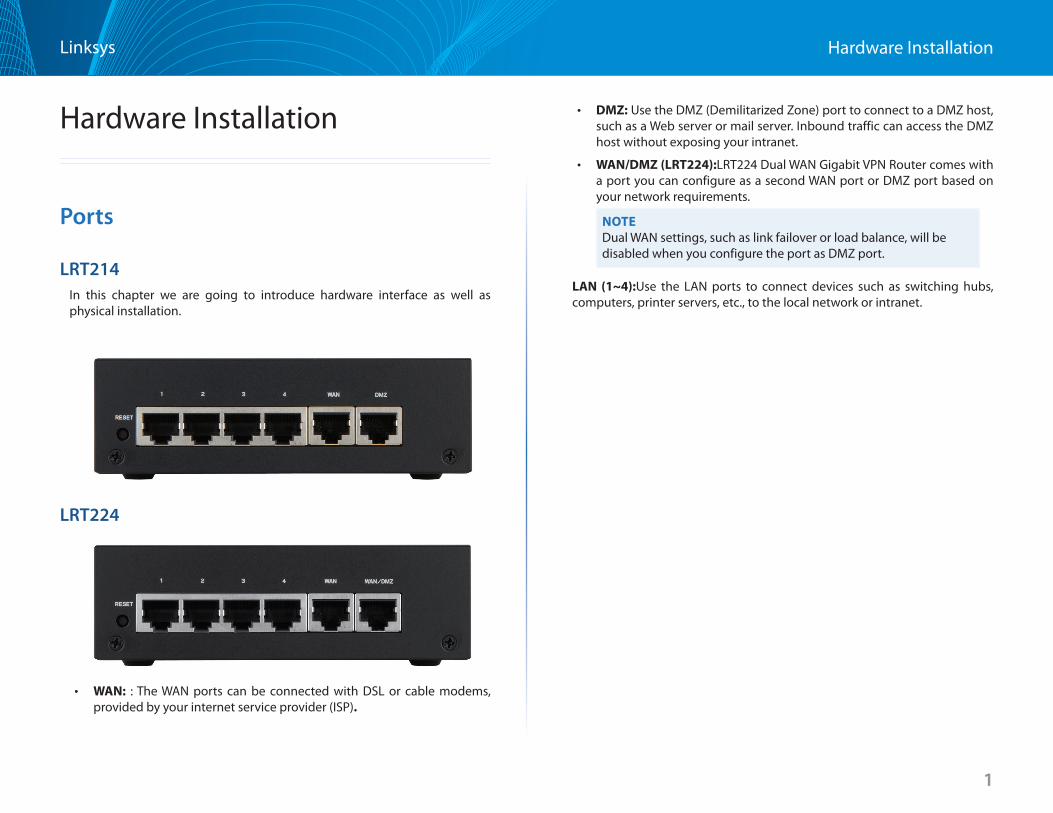
LRT214In this chapter we are going to introduce hardware interface as well as physical installation .
LRT224
• WAN: : The WAN ports can be connected with DSL or cable modems, provided by your internet service provider (ISP)
• DMZ: Use the DMZ (Demilitarized Zone) port to connect to a DMZ host, such as a Web server or mail server . Inbound traffic can access the DMZ host without exposing your intranet .
• WAN/DMZ (LRT224):LRT224 Dual WAN Gigabit VPN Router comes with a port you can configure as a second WAN port or DMZ port based on your network requirements .
NOTEDual WAN settings, such as link failover or load balance, will be disabled when you configure the port as DMZ port .
LAN (1~4):Use the LAN ports to connect devices such as switching hubs, computers, printer servers, etc ., to the local network or intranet .
2
Hardware InstallationLinksys
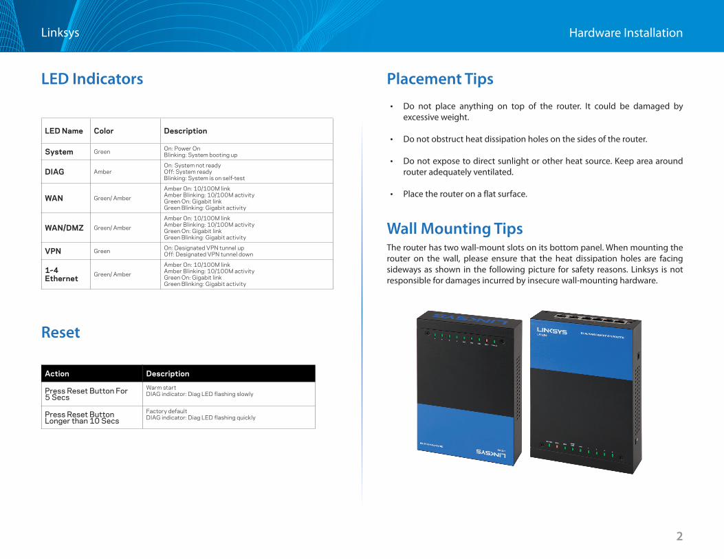
LED Indicators
Reset
Action Description
Press Reset Button For 5 Secs
Warm startDIAG indicator: Diag LED flashing slowly
Press Reset Button Longer than 10 Secs
Factory defaultDIAG indicator: Diag LED flashing quickly
Placement Tips • Do not place anything on top of the router . It could be damaged by
excessive weight .
• Do not obstruct heat dissipation holes on the sides of the router .
• Do not expose to direct sunlight or other heat source . Keep area around router adequately ventilated .
• Place the router on a flat surface .
Wall Mounting TipsThe router has two wall-mount slots on its bottom panel . When mounting the router on the wall, please ensure that the heat dissipation holes are facing sideways as shown in the following picture for safety reasons . Linksys is not responsible for damages incurred by insecure wall-mounting hardware .
LED Name Color Description
System Green On: Power OnBlinking: System booting up
DIAG AmberOn: System not readyOff: System readyBlinking: System is on self-test
WAN Green/ Amber
Amber On: 10/100M linkAmber Blinking: 10/100M activityGreen On: Gigabit linkGreen Blinking: Gigabit activity
WAN/DMZ Green/ Amber
Amber On: 10/100M linkAmber Blinking: 10/100M activityGreen On: Gigabit linkGreen Blinking: Gigabit activity
VPN Green On: Designated VPN tunnel upOff: Designated VPN tunnel down
1~4 Ethernet Green/ Amber
Amber On: 10/100M linkAmber Blinking: 10/100M activityGreen On: Gigabit linkGreen Blinking: Gigabit activity
3
Getting Started with the Router ConfigurationLinksys
3
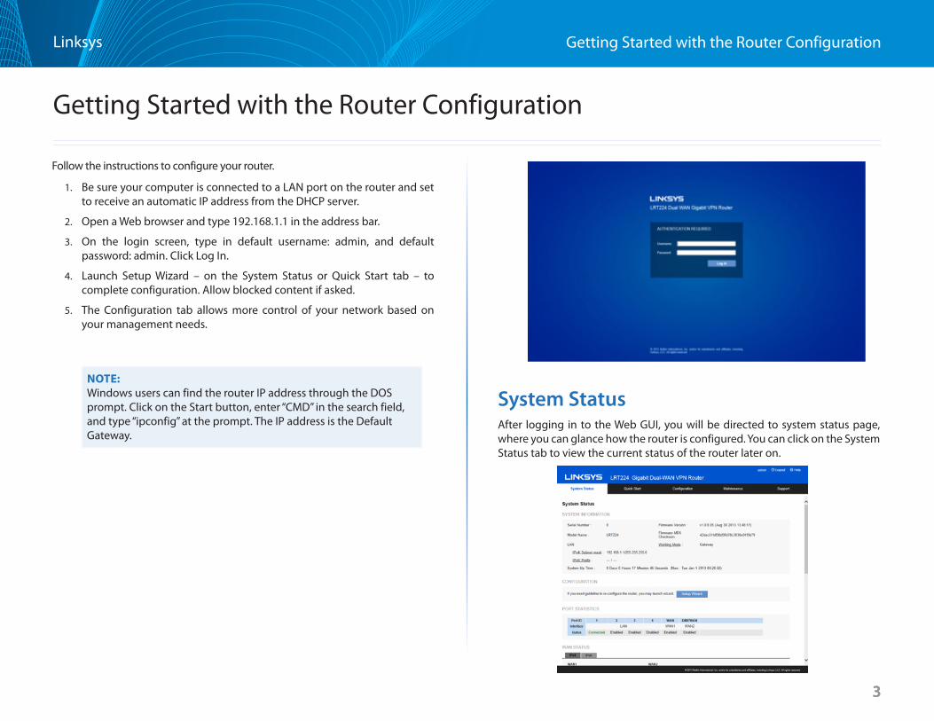
Follow the instructions to configure your router .
1 . Be sure your computer is connected to a LAN port on the router and set to receive an automatic IP address from the DHCP server .
2 . Open a Web browser and type 192 .168 .1 .1 in the address bar .
3 . On the login screen, type in default username: admin, and default password: admin . Click Log In .
4 . Launch Setup Wizard – on the System Status or Quick Start tab – to complete configuration . Allow blocked content if asked .
5 . The Configuration tab allows more control of your network based on your management needs .
NOTE:Windows users can find the router IP address through the DOS prompt . Click on the Start button, enter “CMD” in the search field, and type “ipconfig” at the prompt . The IP address is the Default Gateway .
System StatusAfter logging in to the Web GUI, you will be directed to system status page, where you can glance how the router is configured . You can click on the System Status tab to view the current status of the router later on .
Getting Started with the Router Configuration
4
Getting Started with the Router ConfigurationLinksys
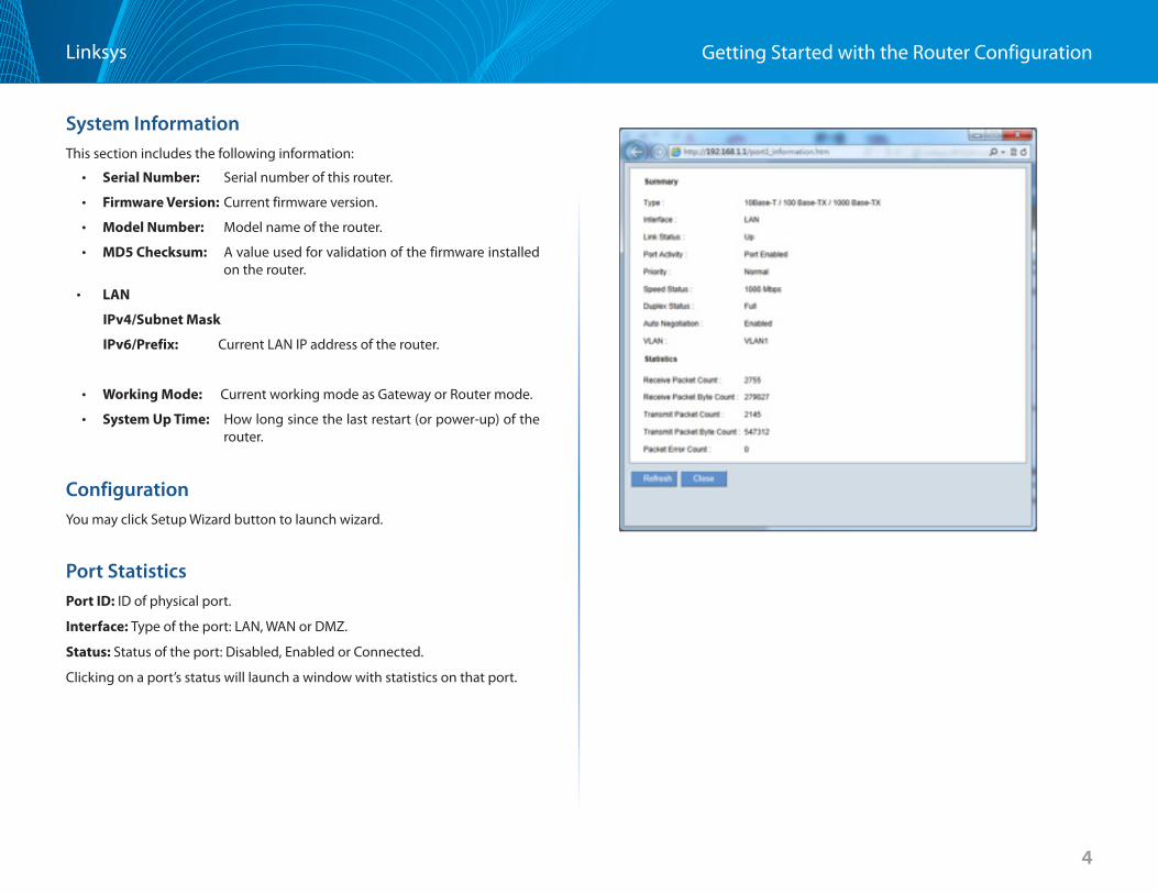
System Information This section includes the following information:
• Serial Number: Serial number of this router .
• Firmware Version: Current firmware version .
• Model Number: Model name of the router .
• MD5 Checksum: A value used for validation of the firmware installed on the router .
• LAN
IPv4/Subnet Mask
IPv6/Prefix: Current LAN IP address of the router .
• Working Mode: Current working mode as Gateway or Router mode .
• System Up Time: How long since the last restart (or power-up) of the router .
ConfigurationYou may click Setup Wizard button to launch wizard .
Port StatisticsPort ID: ID of physical port .
Interface: Type of the port: LAN, WAN or DMZ .
Status: Status of the port: Disabled, Enabled or Connected .
Clicking on a port’s status will launch a window with statistics on that port .
5
Getting Started with the Router ConfigurationLinksys
Type: 10Base-T / 100 Base-TX / 1000 Base-TX .
Interface: LAN/WAN/DMZ .
Link Status: Up or down .
Port Activity: Port Enabled, Port Disabled, or Port Connected .
Priority: High or Normal .
Speed Status: 10Mbps, 100Mbps or 1000Mbps .
Duplex Status : Half or Full .
Auto Negotiation : On or Off .
VLAN : VLAN ID .
This table also gives you the counts for packets received and sent, packet bytes received and sent, and packet errors .
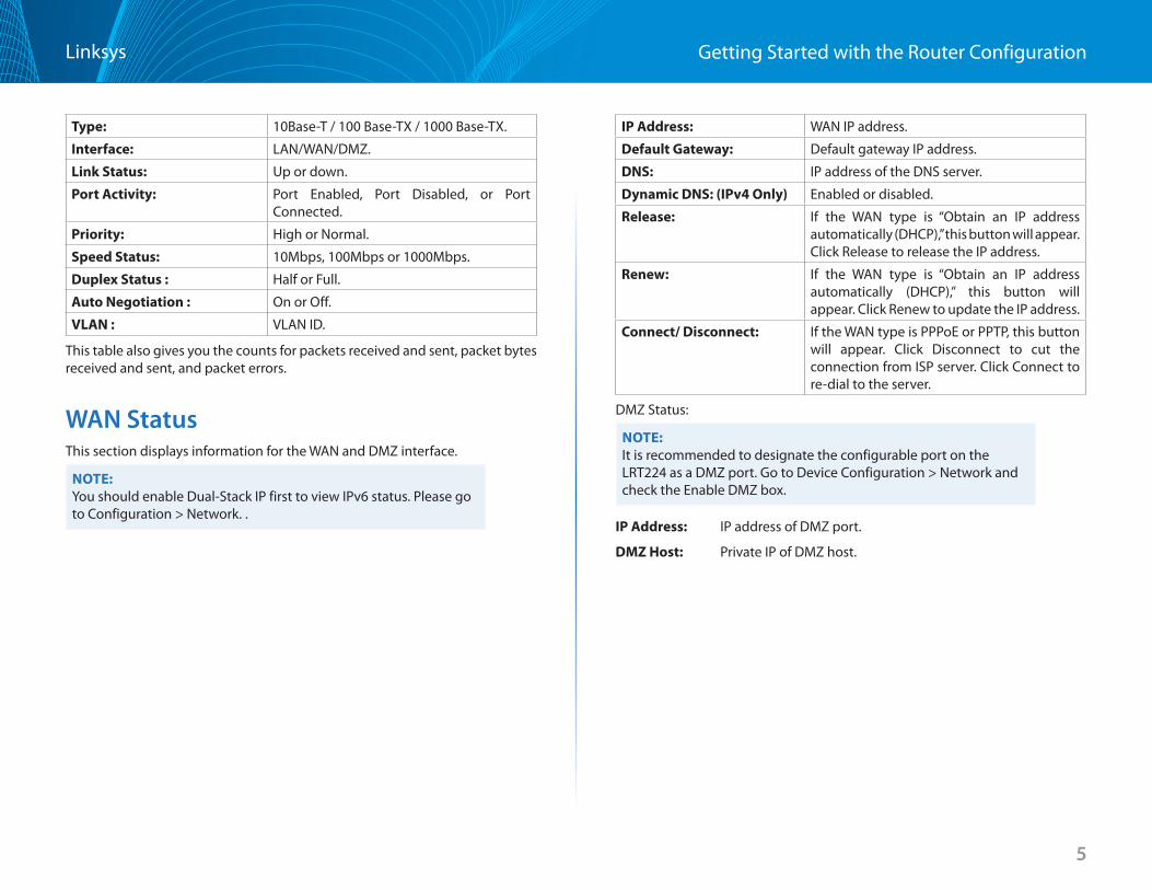
WAN StatusThis section displays information for the WAN and DMZ interface .
NOTE:You should enable Dual-Stack IP first to view IPv6 status . Please go to Configuration > Network . .
IP Address: WAN IP address .
Default Gateway: Default gateway IP address .
DNS: IP address of the DNS server .
Dynamic DNS: (IPv4 Only) Enabled or disabled .
Release: If the WAN type is “Obtain an IP address automatically (DHCP),” this button will appear . Click Release to release the IP address .
Renew: If the WAN type is “Obtain an IP address automatically (DHCP),” this button will appear . Click Renew to update the IP address .
Connect/ Disconnect: If the WAN type is PPPoE or PPTP, this button will appear . Click Disconnect to cut the connection from ISP server . Click Connect to re-dial to the server .
DMZ Status:
NOTE:It is recommended to designate the configurable port on the LRT224 as a DMZ port . Go to Device Configuration > Network and check the Enable DMZ box .
IP Address: IP address of DMZ port .
DMZ Host: Private IP of DMZ host .
6
Getting Started with the Router ConfigurationLinksys
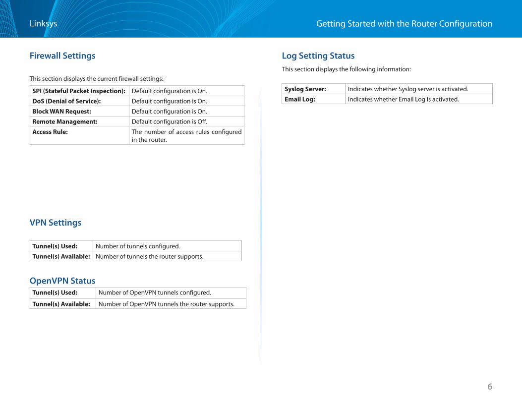
Firewall Settings
This section displays the current firewall settings:
SPI (Stateful Packet Inspection): Default configuration is On .
DoS (Denial of Service): Default configuration is On .
Block WAN Request: Default configuration is On .
Remote Management: Default configuration is Off .
Access Rule: The number of access rules configured in the router .
VPN Settings
Tunnel(s) Used: Number of tunnels configured .
Tunnel(s) Available: Number of tunnels the router supports .
OpenVPN StatusTunnel(s) Used: Number of OpenVPN tunnels configured .
Tunnel(s) Available: Number of OpenVPN tunnels the router supports .
Log Setting Status This section displays the following information:
Syslog Server: Indicates whether Syslog server is activated .
Email Log: Indicates whether Email Log is activated .
7
Getting Started with the Router ConfigurationLinksys
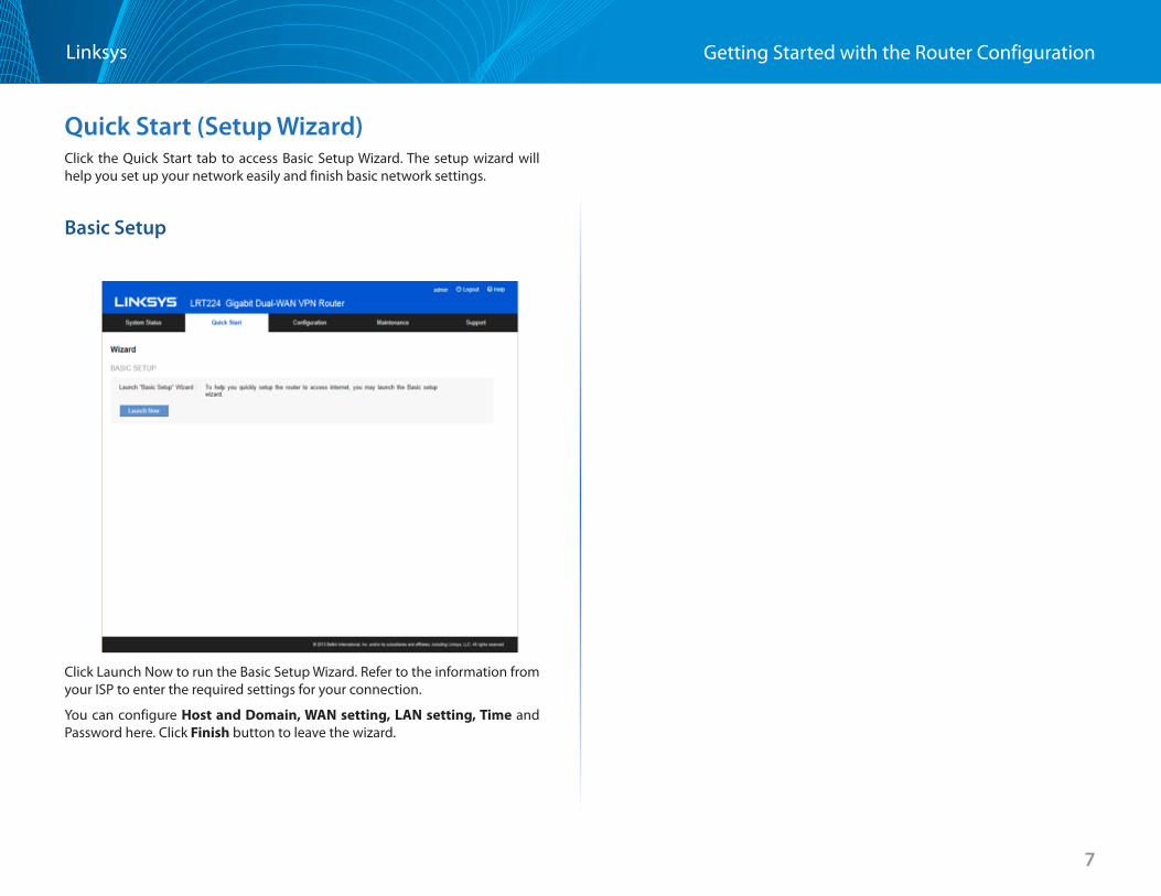
Quick Start (Setup Wizard) Click the Quick Start tab to access Basic Setup Wizard . The setup wizard will help you set up your network easily and finish basic network settings .
Basic Setup
Click Launch Now to run the Basic Setup Wizard . Refer to the information from your ISP to enter the required settings for your connection .
You can configure Host and Domain, WAN setting, LAN setting, Time and Password here . Click Finish button to leave the wizard .
8
SetupLinksys
• Network
• SettingPassword
• Time
• DMZHost
• Forwarding
• PortAddressTranslation
• One-to-OneNAT
• MACAddressClone
• DynamicDNS
• AdvancedRouting
• IPv6Transition
Setup
9
SetupLinksys
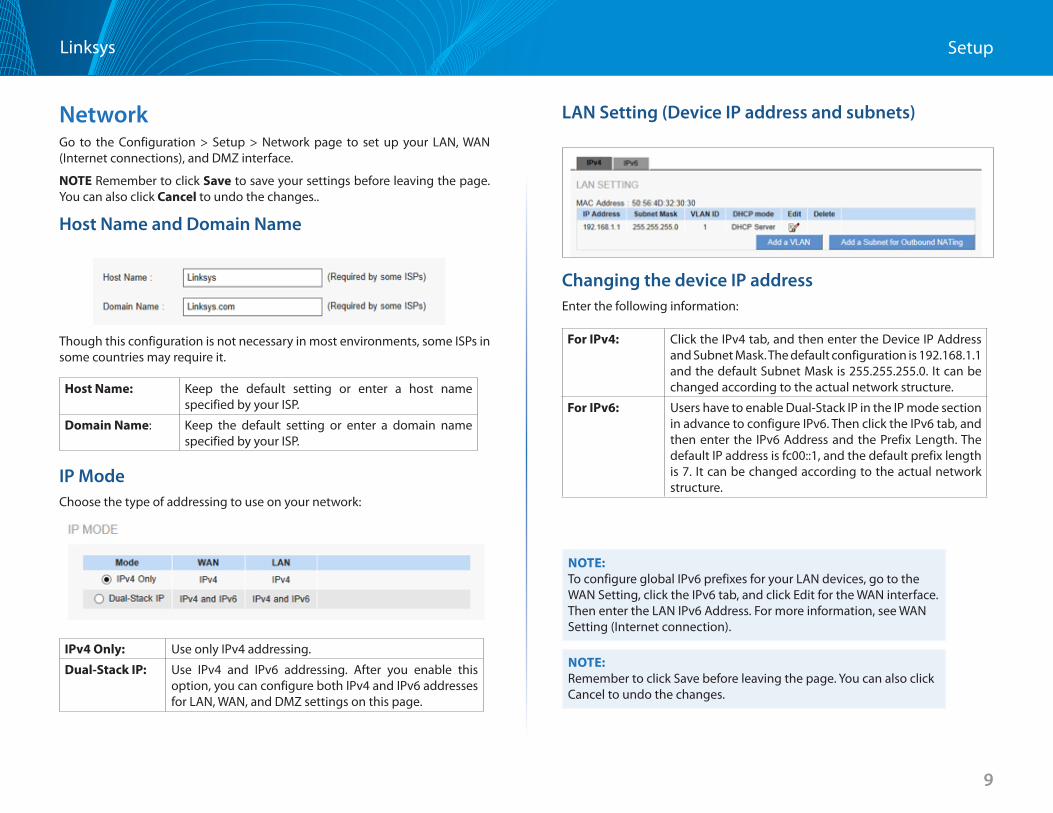
Network Go to the Configuration > Setup > Network page to set up your LAN, WAN (Internet connections), and DMZ interface .
NOTE Remember to click Save to save your settings before leaving the page . You can also click Cancel to undo the changes . .
Host Name and Domain Name
Though this configuration is not necessary in most environments, some ISPs in some countries may require it .
Host Name: Keep the default setting or enter a host name specified by your ISP .
Domain Name: Keep the default setting or enter a domain name specified by your ISP .
IP ModeChoose the type of addressing to use on your network:
IPv4 Only: Use only IPv4 addressing .
Dual-StackIP: Use IPv4 and IPv6 addressing . After you enable this option, you can configure both IPv4 and IPv6 addresses for LAN, WAN, and DMZ settings on this page .
LAN Setting (Device IP address and subnets)
Changing the device IP address
Enter the following information:
For IPv4: Click the IPv4 tab, and then enter the Device IP Address and Subnet Mask . The default configuration is 192 .168 .1 .1 and the default Subnet Mask is 255 .255 .255 .0 . It can be changed according to the actual network structure .
For IPv6: Users have to enable Dual-Stack IP in the IP mode section in advance to configure IPv6 . Then click the IPv6 tab, and then enter the IPv6 Address and the Prefix Length . The default IP address is fc00::1, and the default prefix length is 7 . It can be changed according to the actual network structure .
NOTE:To configure global IPv6 prefixes for your LAN devices, go to the WAN Setting, click the IPv6 tab, and click Edit for the WAN interface . Then enter the LAN IPv6 Address . For more information, see WAN Setting (Internet connection) .
NOTE:Remember to click Save before leaving the page . You can also click Cancel to undo the changes .
10
SetupLinksys
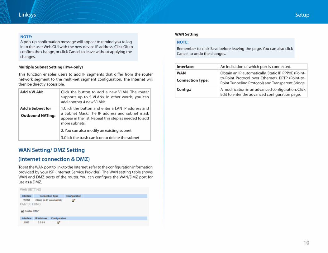
NOTE:A pop-up confirmation message will appear to remind you to log in to the user Web GUI with the new device IP address . Click OK to confirm the change, or click Cancel to leave without applying the changes .
Multiple Subnet Setting (IPv4 only)
This function enables users to add IP segments that differ from the router network segment to the multi-net segment configuration . The Internet will then be directly accessible .
Add a VLAN: Click the button to add a new VLAN . The router supports up to 5 VLANs . In other words, you can add another 4 new VLANs .
Add a Subnet for
Outbound NATing:
1 .Click the button and enter a LAN IP address and a Subnet Mask . The IP address and subnet mask appear in the list . Repeat this step as needed to add more subnets .
2 . You can also modify an existing subnet
3 .Click the trash can icon to delete the subnet
WAN Setting/ DMZ Setting
(Internet connection & DMZ)To set the WAN port to link to the Internet, refer to the configuration information provided by your ISP (Internet Service Provider) . The WAN setting table shows WAN and DMZ ports of the router . You can configure the WAN/DMZ port for use as a DMZ .
WAN Setting
NOTE:
Remember to click Save before leaving the page . You can also click Cancel to undo the changes .
Interface: An indication of which port is connected .
WAN
Connection Type:
Obtain an IP automatically, Static IP, PPPoE (Point-to-Point Protocol over Ethernet), PPTP (Point-to-Point Tunneling Protocol) and Transparent Bridge .
Config : A modification in an advanced configuration . Click Edit to enter the advanced configuration page .
11
SetupLinksys
Obtain an Automatic IP automatically:This mode is often used in the connection mode to obtain an automatic DHCP IP . This is the device system default connection mode . It is a connection mode in which DHCP clients obtain an IP address automatically . To use a different connection mode, refer to the following instructions for selection of appropriate configurations . Users can also set up their own DNS IP address . Check the options and input the user-defined DNS IP addresses .
Use the following DNS Server Addresses:
Select a user-defined DNS server IP address .
DNS Server: Input the DNS IP address set by ISP . At least one IP group should be input . The maximum number of acceptable groups is two .
MTU (Maximum Transmission Unit)
Choose Auto or Manual . Default is Auto . The default value is 1500 . Different value could be set in different network environment (e .g ., ADSL PPPoE MTU: 1492) .
Static IP: If an ISP issues a static IP (such as one IP or eight IP addresses, etc .), please select this connection mode and follow the steps below to input the IP numbers issued by an ISP into the relevant boxes .
Specify WAN IP address: Input the available static IP address issued by your ISP .
Subnet Mask: Input the subnet mask of the static IP address issued by ISP, such as:
Issued eight static IP addresses: 255 .255 .255 .248
Issued 16 static IP addresses: 255 .255 .255 .240
Default Gateway: Input the default gateway issued by ISP . For ADSL users, it is usually an ATU-R IP address . Optical fiber users should input the optical fiber switching IP .
DNS Server: Input the DNS IP address issued by your ISP . At least one IP group should be input . The maximum number of acceptable groups is two .
MTU
(Maximum Transmission Unit):
Choose “Auto” or “Manual .” Default is “Auto .” The default value is 1500 . Different value could be set in different network environment (e .g ., ADSL PPPoE MTU: 1492) .
12
SetupLinksys
PPPoE:This option is for an ADSL virtual dial-up connection (suitable for ADSL PPPoE) .
User Name: Input the user name issued by your ISP .
Password: Input the password issued by your ISP .
Connect on Demand: This function enables the auto-dialing function in a PPPoE dial connection . When the client port attempts to connect with the Internet, the device will automatically make a dial connection . If the line has been idle for a period of time, the system will break the connection automatically . (The default time for automatic disconnection from no packet transmissions is five minutes) .
Keep Alive: This function enables the PPPoE dial connection to keep connected, and to automatically redial if the line is disconnected . It also enables a user to set up a time for redialing . The default is 30 seconds .
Use the following DNS Server Addresses:
Select a user-defined DNS server IP address .
DNS Server: Input the DNS IP address set by ISP . At least one IP group should be input . The maximum number of acceptable groups is two .
MTU (Maximum Transmission Unit)
Choose “Auto” or “Manual” . Default is “Auto .” The default value is 1500 . Different value could be set in different network environment (e .g ., ADSL PPPoE MTU: 1492) .
PPTP:Specify WAN IP Address:
The IP address to be configured could be one issued by your ISP . (The IP address is usually provided by the ISP when the PC is installed . Contact your ISP for relevant information) .
Subnet Mask: Input the subnet mask of the static IP address issued by your ISP, such as:
Issued eight static IP addresses: 255 .255 .255 .248
Issued 16 static IP addresses: 255 .255 .255 .240
Default Gateway: Input the default gateway of the static IP address issued by your ISP . For ADSL users, it is usually an ATU-R IP address .
User Name: Input the user name issued by your ISP .
Password: Input the password issued by your ISP .
Connect on Demand: This function enables the auto-dialing function to be used for a L2TP dial connection . When the client port attempts to connect with the Internet, the device will automatically connect with the default ISP auto dial connection . When the network has been idle for a period of time, the system will break the connection automatically . (The default time for automatic break off when no packets have been transmitted is five minutes) .
Keep Alive: This function enables the L2TP dial connection to redial automatically when the connection has been disconnected . Users can set up the redialing time . The default is 30 seconds .
M T U ( M a x i m u m Transmission Unit):
Choose “Auto” or “Manual” . Default is “Auto .” The default value is 1500 . Different value could be set in different network environment (e .g ., ADSL PPPoE MTU: 1492) .
13
SetupLinksys
L2TPSpecify WAN IP Address
Configure a static IP address . The IP address could be one issued by an L2TP server .
Subnet Mask Input the subnet mask of the static IP address .
Default Gateway Input the IP address of the L2TP server .
Username Input the username of the L2TP client .
Password Input the password of the L2TP client .
Connect on Demand
Enables auto-dialing for a dial connection . When the client port tries to connect to the Internet, the device will automatically connect with the L2TPserver . When the network has been idle for a period of time, the system will break the connection automatically . (The default time for automatic connection break is five minutes) .
Keep Alive Enables the dial connection to redial automatically when disconnected . Set the redialing time (default is 30 seconds) .
MTU Choose Auto or Manual . Default setting is Auto . The default manual setting value is 1500 bytes . A different value could be set in a different network environment (e .g ., ADSL PPPoE MTU: 1492) .
Transparent Bridge:The feature will come in handy in when a company wants to add a firewall or dual-WAN device without changing the IP addresses of the computers in its intranet . This function will enable users to integrate existing networks without changing the original structure . Select the Transparent Bridge mode for the WAN connection mode . In this way, users will be able to connect normally to the Internet while keeping the original IP addresses in the intranet .
If there are two WANs configured, users still can select Transparent Bridge mode for WAN connection mode, and load balancing will still function as usual .
Specify WAN IP Address: Input one of the static IP addresses issued by ISP .
Subnet Mask: Input the subnet mask of the static IP address issued by your ISP, such as: Issued eight static IP addresses: 255 .255 .255 .248 . Issued 16 static IP addresses: 255 .255 .255 .240 .
Default Gateway: Input the default gateway of the static IP address issued by your ISP . For ADSL users, it is usually an ATU-R IP address .
DNS Server: Input the DNS IP address set by your ISP . At least one IP group should be input . The maximum acceptable is two IP groups .
Internal LAN IP Range: Input the available IP range issued by your ISP . If your ISP issued two discontinuous IP address ranges, users can input them into Internal LAN IP Range 1 and Internal LAN IP Range 2, respectively .
MTU (Maximum Transmission Unit):
MTU is abbreviation of Maximum Transmission Unit . “Auto” and “Manual” can be chosen . The default value is 1500 . Different value could be set in different network environment . (e .g . ADSL PPPoE MTU: 1492)
The default is “Auto” .
DMZ SettingFor some network environments, an independent configurable DMZ port may be required to set up externally connected servers such as WEB and Mail servers . Therefore, the device supports a set of independent configurable DMZ ports for users to set up connections for servers with real IP addresses . The DMZ ports act as bridges between the Internet and LANs .
Check Enable DMZ box and click the edit icon to configure DMZ port .
The DMZ configuration can be classified by subnet and range:
14
SetupLinksys
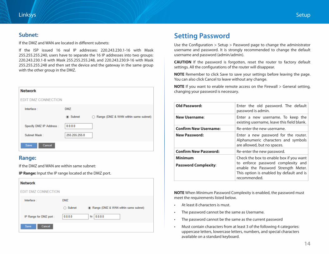
Subnet:If the DMZ and WAN are located in different subnets:
If the ISP issued 16 real IP addresses: 220 .243 .230 .1-16 with Mask 255 .255 .255 .240, users have to separate the 16 IP addresses into two groups: 220 .243 .230 .1-8 with Mask 255 .255 .255 .248, and 220 .243 .230 .9-16 with Mask 255 .255 .255 .248 and then set the device and the gateway in the same group with the other group in the DMZ .
Range:If the DMZ and WAN are within same subnet:
IP Range: Input the IP range located at the DMZ port .
Setting PasswordUse the Configuration > Setup > Password page to change the administrator username and password . It is strongly recommended to change the default username and password (admin/admin) .
CAUTION If the password is forgotten, reset the router to factory default settings . All the configurations of the router will disappear .
NOTE Remember to click Save to save your settings before leaving the page . You can also click Cancel to leave without any change .
NOTE If you want to enable remote access on the Firewall > General setting, changing your password is necessary .
Old Password: Enter the old password . The default password is admin .
New Username: Enter a new username . To keep the existing username, leave this field blank .
Confirm New Username: Re-enter the new username .
New Password: Enter a new password for the router . Alphanumeric characters and symbols are allowed, but no spaces .
Confirm New Password: Re-enter the new password .
Minimum
Password Complexity:
Check the box to enable box if you want to enforce password complexity and enable the Password Strength Meter . This option is enabled by default and is recommended .
NOTE When Minimum Password Complexity is enabled, the password must meet the requirements listed below .
• At least 8 characters is must .
• The password cannot be the same as Username .
• The password cannot be the same as the current password
• Must contain characters from at least 3 of the following 4 categories: uppercase letters, lowercase letters, numbers, and special characters available on a standard keyboard .
15
SetupLinksys
Password Strength Meter: When enabling Minimum Password Complexity, the Password Strength Meter appears and indicates the password strength .
Red means you have to reset the password .Yellow means the password is acceptable . Green means the password is strong .
Password
Aging Enforcement:
Choose Disable to make the password permanent . Choose Change the password after if you want the password to expire after the specified period . Check Change the password after and input the specified number of Days .
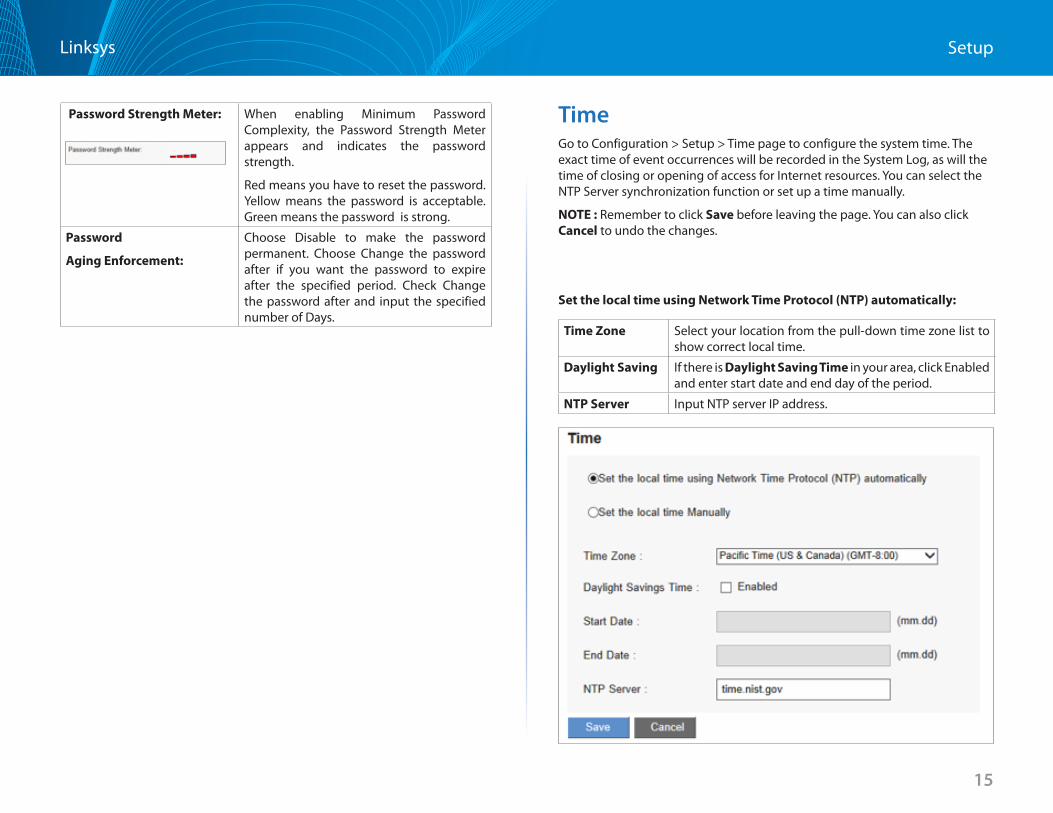
TimeGo to Configuration > Setup > Time page to configure the system time . The exact time of event occurrences will be recorded in the System Log, as will the time of closing or opening of access for Internet resources . You can select the NTP Server synchronization function or set up a time manually .
NOTE : Remember to click Save before leaving the page . You can also click Cancel to undo the changes .
Set the local time using Network Time Protocol (NTP) automatically:
Time Zone Select your location from the pull-down time zone list to show correct local time .
Daylight Saving If there is Daylight Saving Time in your area, click Enabled and enter start date and end day of the period .
NTP Server Input NTP server IP address .
16
SetupLinksys
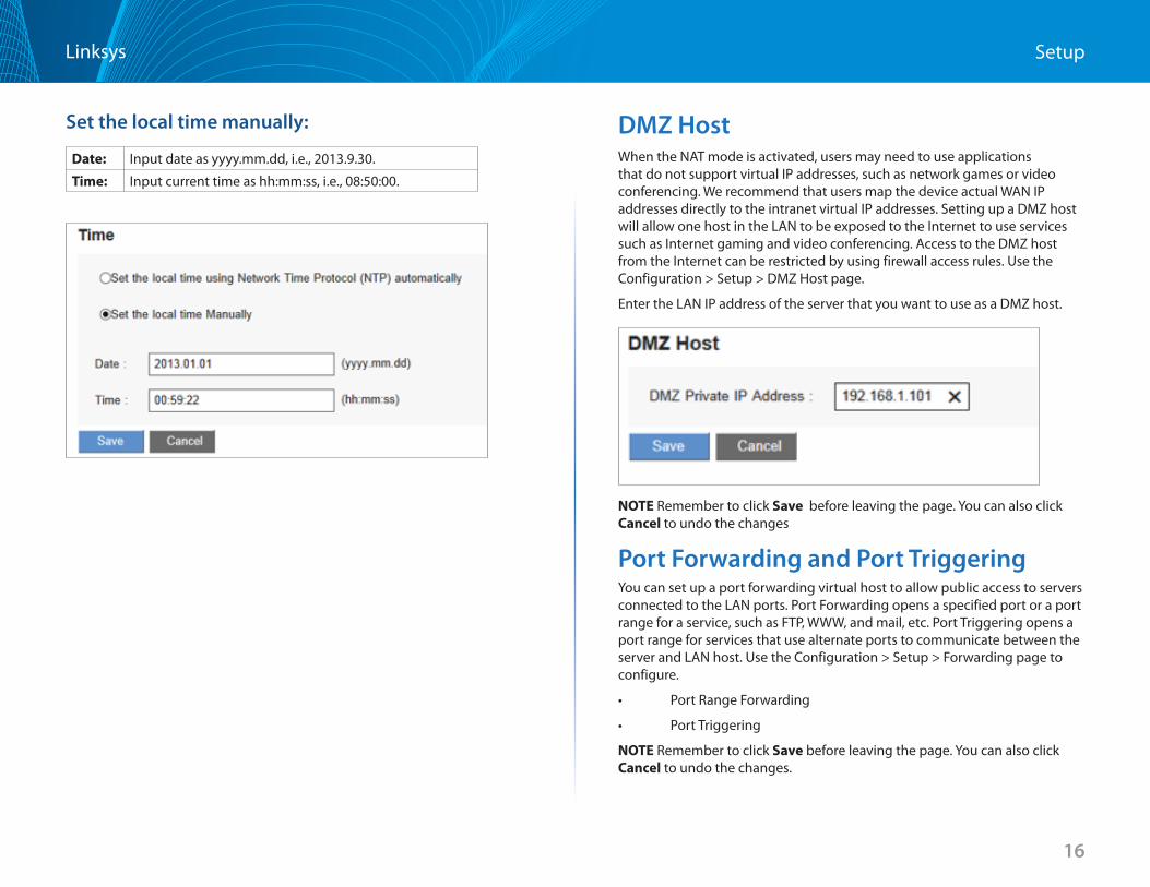
Set the local time manually:
Date: Input date as yyyy .mm .dd, i .e ., 2013 .9 .30 .
Time: Input current time as hh:mm:ss, i .e ., 08:50:00 .
DMZ HostWhen the NAT mode is activated, users may need to use applications that do not support virtual IP addresses, such as network games or video conferencing . We recommend that users map the device actual WAN IP addresses directly to the intranet virtual IP addresses . Setting up a DMZ host will allow one host in the LAN to be exposed to the Internet to use services such as Internet gaming and video conferencing . Access to the DMZ host from the Internet can be restricted by using firewall access rules . Use the Configuration > Setup > DMZ Host page .
Enter the LAN IP address of the server that you want to use as a DMZ host .
NOTE Remember to click Save before leaving the page . You can also click Cancel to undo the changes
Port Forwarding and Port TriggeringYou can set up a port forwarding virtual host to allow public access to servers connected to the LAN ports . Port Forwarding opens a specified port or a port range for a service, such as FTP, WWW, and mail, etc . Port Triggering opens a port range for services that use alternate ports to communicate between the server and LAN host . Use the Configuration > Setup > Forwarding page to configure .
• PortRangeForwarding
• PortTriggering
NOTE Remember to click Save before leaving the page . You can also click Cancel to undo the changes .
17
SetupLinksys
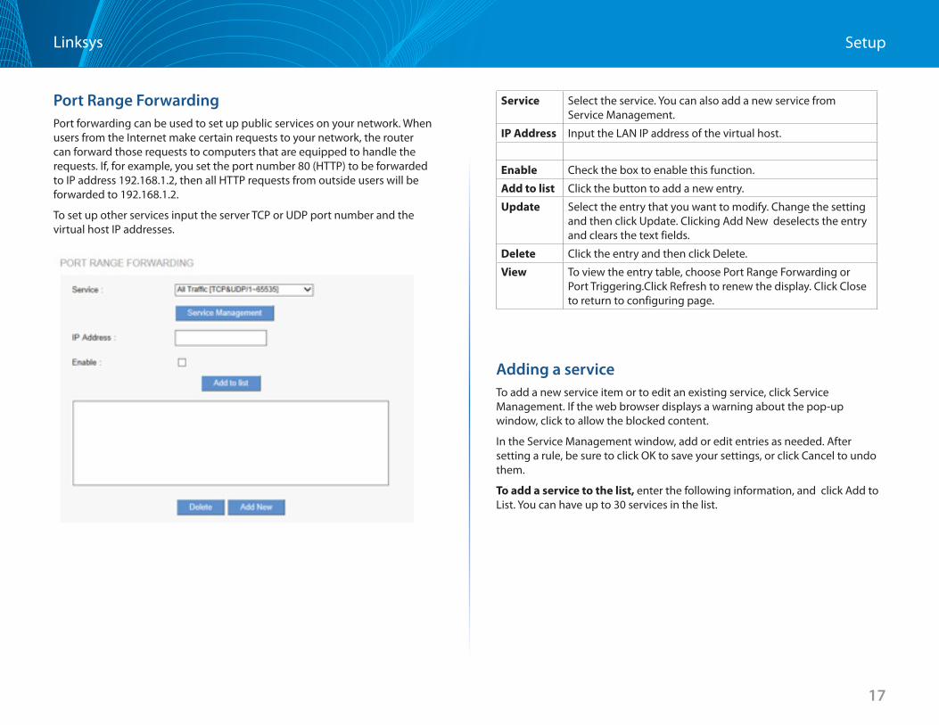
Port Range Forwarding Port forwarding can be used to set up public services on your network . When users from the Internet make certain requests to your network, the router can forward those requests to computers that are equipped to handle the requests . If, for example, you set the port number 80 (HTTP) to be forwarded to IP address 192 .168 .1 .2, then all HTTP requests from outside users will be forwarded to 192 .168 .1 .2 .
To set up other services input the server TCP or UDP port number and the virtual host IP addresses .
Service Select the service . You can also add a new service from Service Management .
IP Address Input the LAN IP address of the virtual host .
Enable Check the box to enable this function .
Add to list Click the button to add a new entry .
Update Select the entry that you want to modify . Change the setting and then click Update . Clicking Add New deselects the entry and clears the text fields .
Delete Click the entry and then click Delete .
View To view the entry table, choose Port Range Forwarding or Port Triggering .Click Refresh to renew the display . Click Close to return to configuring page .
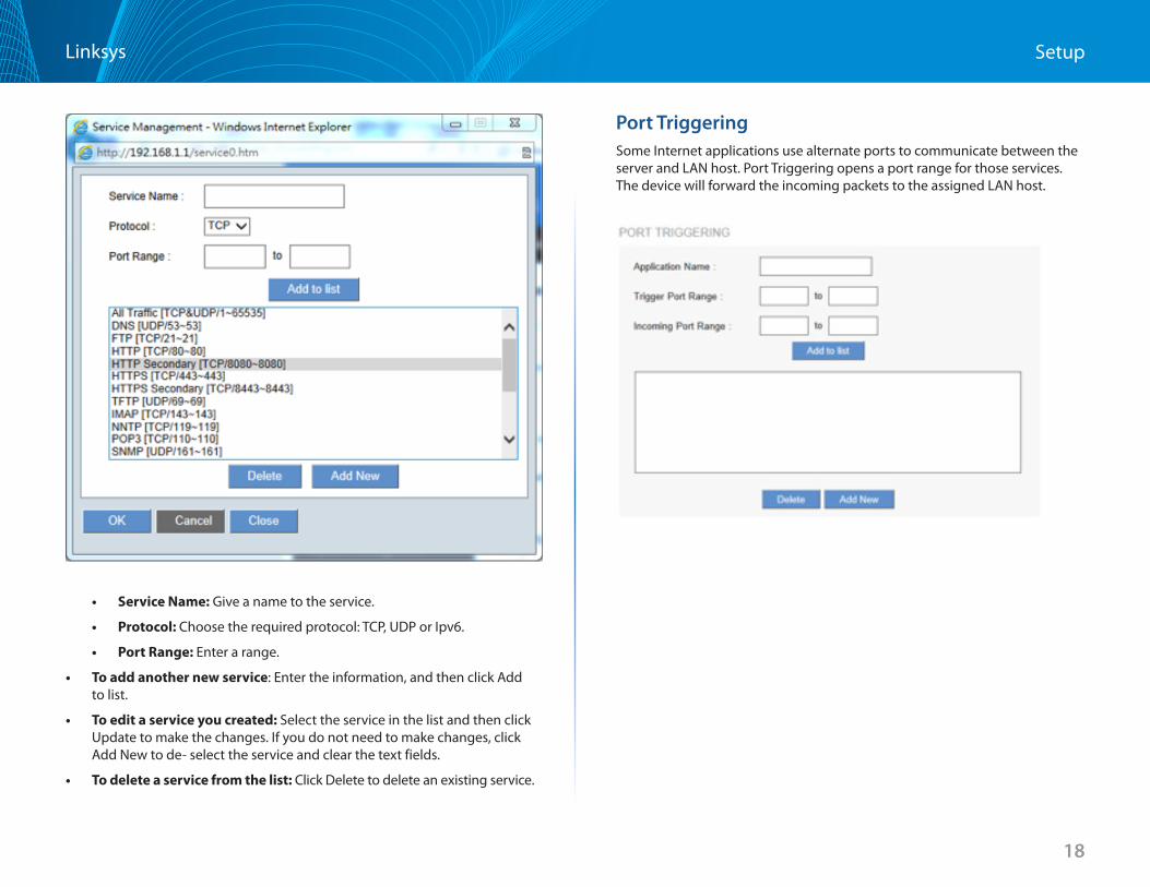
Adding a service To add a new service item or to edit an existing service, click Service Management . If the web browser displays a warning about the pop-up window, click to allow the blocked content .
In the Service Management window, add or edit entries as needed . After setting a rule, be sure to click OK to save your settings, or click Cancel to undo them .
To add a service to the list, enter the following information, and click Add to List . You can have up to 30 services in the list .
18
SetupLinksys
• Service Name: Give a name to the service .
• Protocol: Choose the required protocol: TCP, UDP or Ipv6 .
• Port Range: Enter a range .
• To add another new service: Enter the information, and then click Add to list .
• To edit a service you created: Select the service in the list and then click Update to make the changes . If you do not need to make changes, click Add New to de- select the service and clear the text fields .
• To delete a service from the list: Click Delete to delete an existing service .
Port TriggeringSome Internet applications use alternate ports to communicate between the server and LAN host . Port Triggering opens a port range for those services . The device will forward the incoming packets to the assigned LAN host .
19
SetupLinksys
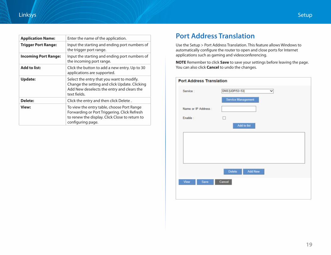
Application Name: Enter the name of the application .
Trigger Port Range: Input the starting and ending port numbers of the trigger port range .
Incoming Port Range: Input the starting and ending port numbers of the incoming port range .
Add to list: Click the button to add a new entry . Up to 30 applications are supported .
Update: Select the entry that you want to modify . Change the setting and click Update . Clicking Add New deselects the entry and clears the text fields .
Delete: Click the entry and then click Delete .
View: To view the entry table, choose Port Range Forwarding or Port Triggering . Click Refresh to renew the display . Click Close to return to configuring page .
Port Address Translation Use the Setup > Port Address Translation . This feature allows Windows to automatically configure the router to open and close ports for Internet applications such as gaming and videoconferencing .
NOTE Remember to click Save to save your settings before leaving the page . You can also click Cancel to undo the changes .
20
SetupLinksys
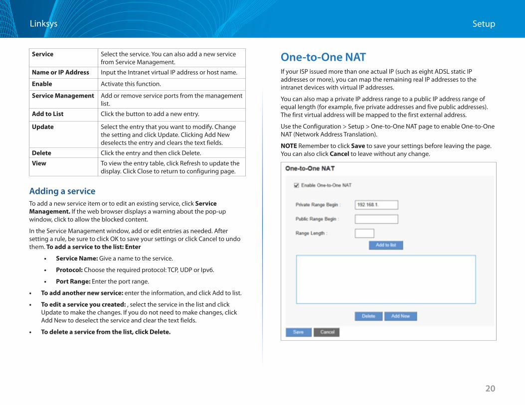
Service Select the service . You can also add a new service from Service Management .
Name or IP Address Input the Intranet virtual IP address or host name .
Enable Activate this function .
Service Management Add or remove service ports from the management list .
Add to List Click the button to add a new entry .
Update Select the entry that you want to modify . Change the setting and click Update . Clicking Add New deselects the entry and clears the text fields .
Delete Click the entry and then click Delete .
View To view the entry table, click Refresh to update the display . Click Close to return to configuring page .
Adding a service To add a new service item or to edit an existing service, click Service Management If the web browser displays a warning about the pop-up window, click to allow the blocked content .
In the Service Management window, add or edit entries as needed . After setting a rule, be sure to click OK to save your settings or click Cancel to undo them . To add a service to the list: Enter
• Service Name: Give a name to the service .
• Protocol: Choose the required protocol: TCP, UDP or Ipv6 .
• Port Range: Enter the port range .
• To add another new service: enter the information, and click Add to list .
• To edit a service you created: , select the service in the list and click Update to make the changes . If you do not need to make changes, click Add New to deselect the service and clear the text fields .
• To delete a service from the list, click Delete
One-to-One NAT If your ISP issued more than one actual IP (such as eight ADSL static IP addresses or more), you can map the remaining real IP addresses to the intranet devices with virtual IP addresses .
You can also map a private IP address range to a public IP address range of equal length (for example, five private addresses and five public addresses) . The first virtual address will be mapped to the first external address .
Use the Configuration > Setup > One-to-One NAT page to enable One-to-One NAT (Network Address Translation) .
NOTE Remember to click Save to save your settings before leaving the page . You can also click Cancel to leave without any change .
21
SetupLinksys
Enabled One to One NAT: Check to enable the One-to-One NAT function .
Private Range Begin: Input the Private IP address for the Intranet One-to-One NAT function .
Public Range Begin: Input the Public IP address for the Internet One-to-One NAT function .
Range Length: Input the numbers of final IP addresses of actual Internet IP addresses . (Please do not include IP addresses in use by WAN ports .)
Add to List: Add this configuration to the One-to-One NAT list .
Update: Select the entry that you want to modify . Change the setting and click Update . Clicking Add New will deselect the entry and clear the text fields .
Delete: Click the entry and then click Delete .
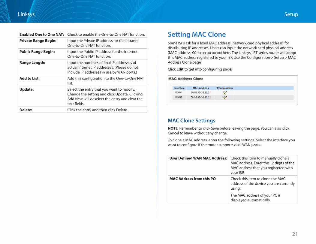
Setting MAC Clone Some ISPs ask for a fixed MAC address (network card physical address) for distributing IP addresses . Users can input the network card physical address (MAC address: 00-xx-xx-xx-xx-xx) here . The Linksys LRT series router will adopt this MAC address registered to your ISP . Use the Configuration > Setup > MAC Address Clone page
Click Edit to get into configuring page .
MAC Clone Settings NOTE Remember to click Save before leaving the page . You can also click Cancel to leave without any change .
To clone a MAC address, enter the following settings . Select the interface you want to configure if the router supports dual WAN ports .
User Defined WAN MAC Address: Check this item to manually clone a MAC address . Enter the 12 digits of the MAC address that you registered with your ISP .
MAC Address from this PC: Check this item to clone the MAC address of the device you are currently using .
The MAC address of your PC is displayed automatically .
22
SetupLinksys
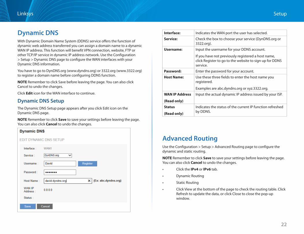
Dynamic DNSWith Dynamic Domain Name System (DDNS) service offers the function of dynamic web address transferred you can assign a domain name to a dynamic WAN IP address . This function will benefit VPN connection, website, FTP or other TCP/IP service in dynamic IP address network . Use the Configuration > Setup > Dynamic DNS page to configure the WAN interfaces with your Dynamic DNS information .
You have to go to DynDNS .org (www .dyndns .org) or 3322 .org (www .3322 .org) to register a domain name before configuring DDNS function .
NOTE Remember to click Save before leaving the page . You can also click Cancel to undo the changes .
Click Edit icon for the WAN interface to continue .
Dynamic DNS Setup The Dynamic DNS Setup page appears after you click Edit icon on the Dynamic DNS page .
NOTE Remember to click Save to save your settings before leaving the page . You can also click Cancel to undo the changes .
Interface: Indicates the WAN port the user has selected .
Service: Check the box to choose your service (DynDNS .org or 3322 .org) .
Username: Input the username for your DDNS account .
If you have not previously registered a host name, click Register to go to the website to sign up for DDNS service .
Password: Enter the password for your account .
Host Name: Use these three fields to enter the host name you registered .
Examples are abc .dyndns .org or xyz .3322 .org .
WAN IP Address
(Read only)
Input the actual dynamic IP address issued by your ISP .
Status
(Read only)
Indicates the status of the current IP function refreshed by DDNS .
Advanced Routing Use the Configuration > Setup > Advanced Routing page to configure the dynamic and static routing .
NOTE Remember to click Save to save your settings before leaving the page . You can also click Cancel to undo the changes .
• ClicktheIPv4 or IPv6 tab .
• DynamicRouting
• StaticRouting
• ClickViewatthebottomofthepagetochecktheroutingtable.Click Refresh to update the data, or click Close to close the pop-up window .
23
SetupLinksys
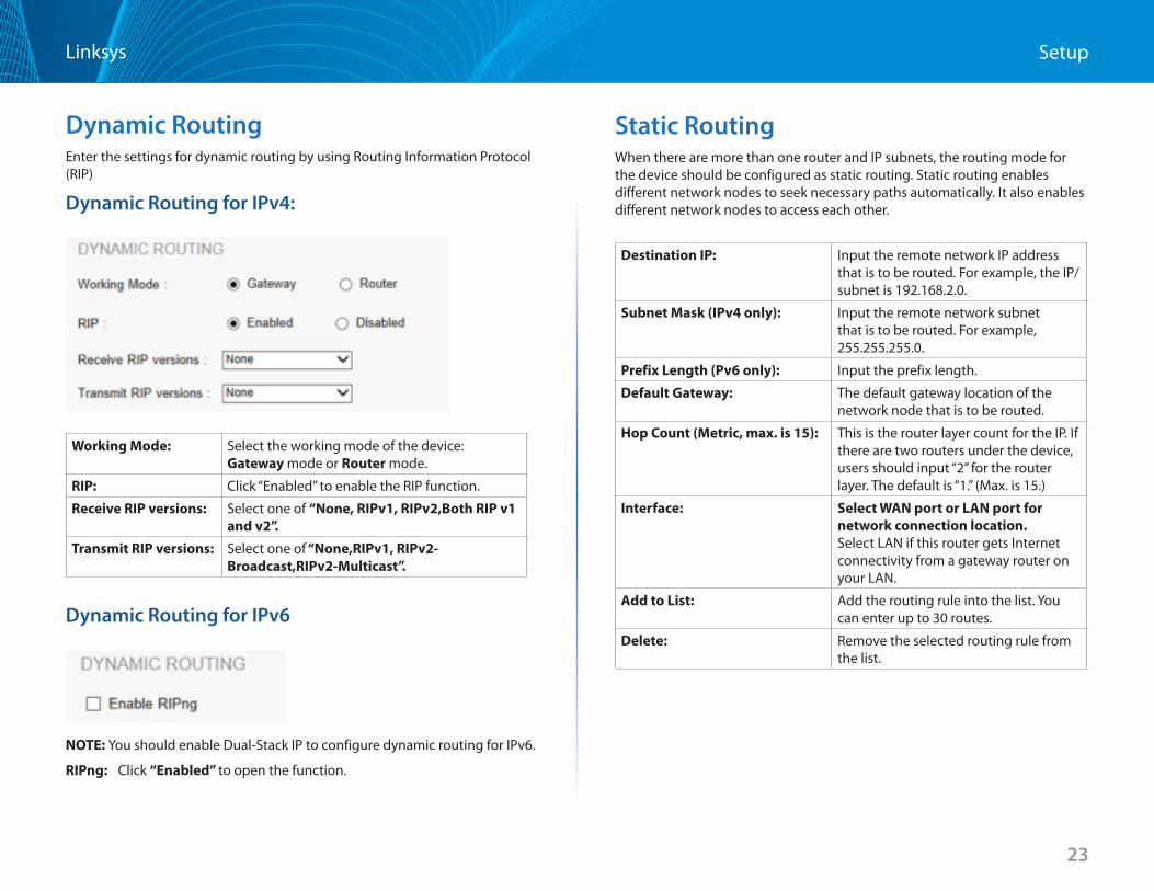
Dynamic RoutingEnter the settings for dynamic routing by using Routing Information Protocol (RIP)
Dynamic Routing for IPv4:
Working Mode: Select the working mode of the device: Gateway mode or Router mode .
RIP: Click “Enabled” to enable the RIP function .
Receive RIP versions: Select one of “None, RIPv1, RIPv2,Both RIP v1 and v2”
Transmit RIP versions: Select one of“None,RIPv1,RIPv2-Broadcast,RIPv2-Multicast”.
Dynamic Routing for IPv6
NOTE: You should enable Dual-Stack IP to configure dynamic routing for IPv6 .
RIPng: Click “Enabled” to open the function .
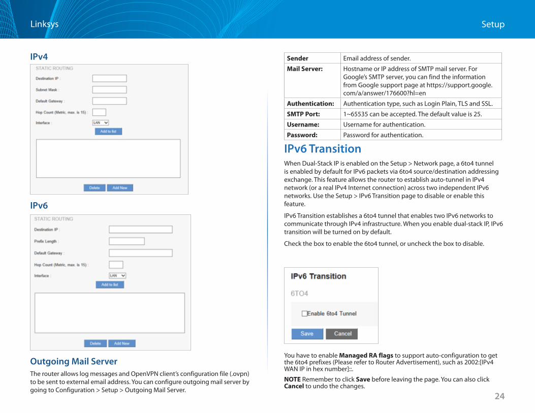
Static RoutingWhen there are more than one router and IP subnets, the routing mode for the device should be configured as static routing . Static routing enables different network nodes to seek necessary paths automatically . It also enables different network nodes to access each other .
Destination IP: Input the remote network IP address that is to be routed . For example, the IP/subnet is 192 .168 .2 .0 .
Subnet Mask (IPv4 only): Input the remote network subnet that is to be routed . For example, 255 .255 .255 .0 .
Prefix Length (Pv6 only): Input the prefix length .
Default Gateway: The default gateway location of the network node that is to be routed .
Hop Count (Metric, max is 15): This is the router layer count for the IP . If there are two routers under the device, users should input “2” for the router layer . The default is “1 .” (Max . is 15 .)
Interface: Select WAN port or LAN port for network connection location Select LAN if this router gets Internet connectivity from a gateway router on your LAN .
Add to List: Add the routing rule into the list . You can enter up to 30 routes .
Delete: Remove the selected routing rule from the list .
24
SetupLinksys
IPv4
IPv6
Outgoing Mail Server The router allows log messages and OpenVPN client’s configuration file ( .ovpn) to be sent to external email address . You can configure outgoing mail server by going to Configuration > Setup > Outgoing Mail Server .
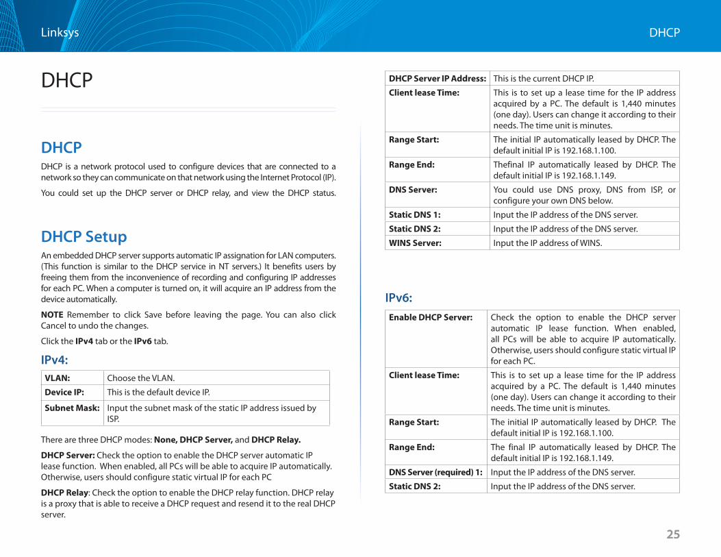
IPv6 TransitionWhen Dual-Stack IP is enabled on the Setup > Network page, a 6to4 tunnel is enabled by default for IPv6 packets via 6to4 source/destination addressing exchange . This feature allows the router to establish auto-tunnel in IPv4 network (or a real IPv4 Internet connection) across two independent IPv6 networks . Use the Setup > IPv6 Transition page to disable or enable this feature .
IPv6 Transition establishes a 6to4 tunnel that enables two IPv6 networks to communicate through IPv4 infrastructure . When you enable dual-stack IP, IPv6 transition will be turned on by default .
Check the box to enable the 6to4 tunnel, or uncheck the box to disable .
box to disable .
You have to enable Managed RA flags to support auto-configuration to get the 6to4 prefixes (Please refer to Router Advertisement), such as 2002:[IPv4 WAN IP in hex number]:: .
NOTE Remember to click Save before leaving the page . You can also click Cancel to undo the changes .
Sender Email address of sender .
Mail Server: Hostname or IP address of SMTP mail server . For Google’s SMTP server, you can find the information from Google support page at https://support .google .com/a/answer/176600?hl=en
Authentication: Authentication type, such as Login Plain, TLS and SSL .
SMTP Port: 1~65535 can be accepted . The default value is 25 .
Username: Username for authentication .
Password: Password for authentication .
25
DHCPLinksys
25
DHCP
DHCPDHCP is a network protocol used to configure devices that are connected to a network so they can communicate on that network using the Internet Protocol (IP) .
You could set up the DHCP server or DHCP relay, and view the DHCP status .
DHCP SetupAn embedded DHCP server supports automatic IP assignation for LAN computers . (This function is similar to the DHCP service in NT servers .) It benefits users by freeing them from the inconvenience of recording and configuring IP addresses for each PC . When a computer is turned on, it will acquire an IP address from the device automatically .
NOTE Remember to click Save before leaving the page . You can also click Cancel to undo the changes .
Click the IPv4 tab or the IPv6 tab .
IPv4:VLAN: Choose the VLAN .
Device IP: This is the default device IP .
Subnet Mask: Input the subnet mask of the static IP address issued by ISP .
There are three DHCP modes: None, DHCP Server, and DHCP Relay
DHCP Server: Check the option to enable the DHCP server automatic IP lease function . When enabled, all PCs will be able to acquire IP automatically . Otherwise, users should configure static virtual IP for each PC
DHCP Relay: Check the option to enable the DHCP relay function . DHCP relay is a proxy that is able to receive a DHCP request and resend it to the real DHCP server .
DHCP Server IP Address: This is the current DHCP IP .
Client lease Time: This is to set up a lease time for the IP address acquired by a PC . The default is 1,440 minutes (one day) . Users can change it according to their needs . The time unit is minutes .
Range Start: The initial IP automatically leased by DHCP . The default initial IP is 192 .168 .1 .100 .
Range End: Thefinal IP automatically leased by DHCP . The default initial IP is 192 .168 .1 .149 .
DNS Server: You could use DNS proxy, DNS from ISP, or configure your own DNS below .
Static DNS 1: Input the IP address of the DNS server .
Static DNS 2: Input the IP address of the DNS server .
WINS Server: Input the IP address of WINS .
IPv6: Enable DHCP Server: Check the option to enable the DHCP server
automatic IP lease function . When enabled, all PCs will be able to acquire IP automatically . Otherwise, users should configure static virtual IP for each PC .
Client lease Time: This is to set up a lease time for the IP address acquired by a PC . The default is 1,440 minutes (one day) . Users can change it according to their needs . The time unit is minutes .
Range Start: The initial IP automatically leased by DHCP . The default initial IP is 192 .168 .1 .100 .
Range End: The final IP automatically leased by DHCP . The default initial IP is 192 .168 .1 .149 .
DNS Server (required) 1: Input the IP address of the DNS server .
Static DNS 2: Input the IP address of the DNS server .
26
DHCPLinksys
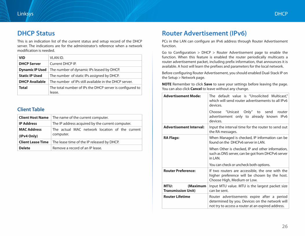
DHCP StatusThis is an indication list of the current status and setup record of the DHCP server . The indications are for the administrator’s reference when a network modification is needed .
VID VLAN ID .
DHCP Server Current DHCP IP .
Dynamic IP Used The number of dynamic IPs leased by DHCP .
Static IP Used The number of static IPs assigned by DHCP .
DHCP Available The number of IPs still available in the DHCP server .
Total The total number of IPs the DHCP server is configured to lease .
Client TableClient Host Name The name of the current computer .
IP Address The IP address acquired by the current computer .
MAC Address
(IPv4 Only)
The actual MAC network location of the current computer .
Client Lease Time The lease time of the IP released by DHCP .
Delete Remove a record of an IP lease .
Router Advertisement (IPv6)PCs in the LAN can configure an IPv6 address through Router Advertisement function .
Go to Configuration > DHCP > Router Advertisement page to enable the function . When this feature is enabled the router periodically multicasts a router advertisement packet, including prefix information, that announces it is available . A host will learn the prefixes and parameters for the local network .
Before configuring Router Advertisement, you should enabled Dual-Stack IP on the Setup > Network page .
NOTE Remember to click Save to save your settings before leaving the page . You can also click Cancel to leave without any change .
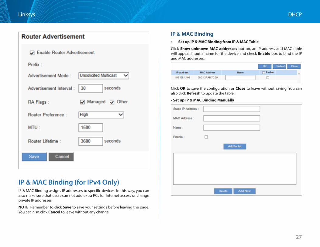
Advertisement Mode: The default value is “Unsolicited Multicast,” which will send router advertisements to all IPv6 devices .
Choose “Unicast Only” to send router advertisement only to already known IPv6 devices .
Advertisement Interval: Input the interval time for the router to send out the RA messages .
RA Flags: When Managed is checked, IP information can be found on the DHCPv6 server in LAN .
When Other is checked, IP and other information, such as DNS server, can be got from DHCPv6 server in LAN .
You can check or uncheck both options .
Router Preference: If two routers are accessible, the one with the higher preference will be chosen by the host . Choose High, Medium or Low .
MTU: (Maximum Transmission Unit)
Input MTU value . MTU is the largest packet size can be sent .
Router Lifetime Router advertisements expire after a period determined by you . Devices on the network will not try to access a router at an expired address .
27
DHCPLinksys
IP & MAC Binding (for IPv4 Only)IP & MAC Binding assigns IP addresses to specific devices . In this way, you can also make sure that users can not add extra PCs for Internet access or change private IP addresses .
NOTE Remember to click Save to save your settings before leaving the page . You can also click Cancel to leave without any change .
IP & MAC Binding • Set up IP & MAC Binding from IP & MAC Table
Click Show unknown MAC addresses button, an IP address and MAC table will appear . Input a name for the device and check Enable box to bind the IP and MAC addresses .
Click OK to save the configuration or Close to leave without saving . You can also click Refresh to update the table .
-SetupIP&MACBindingManually
28
DHCPLinksys
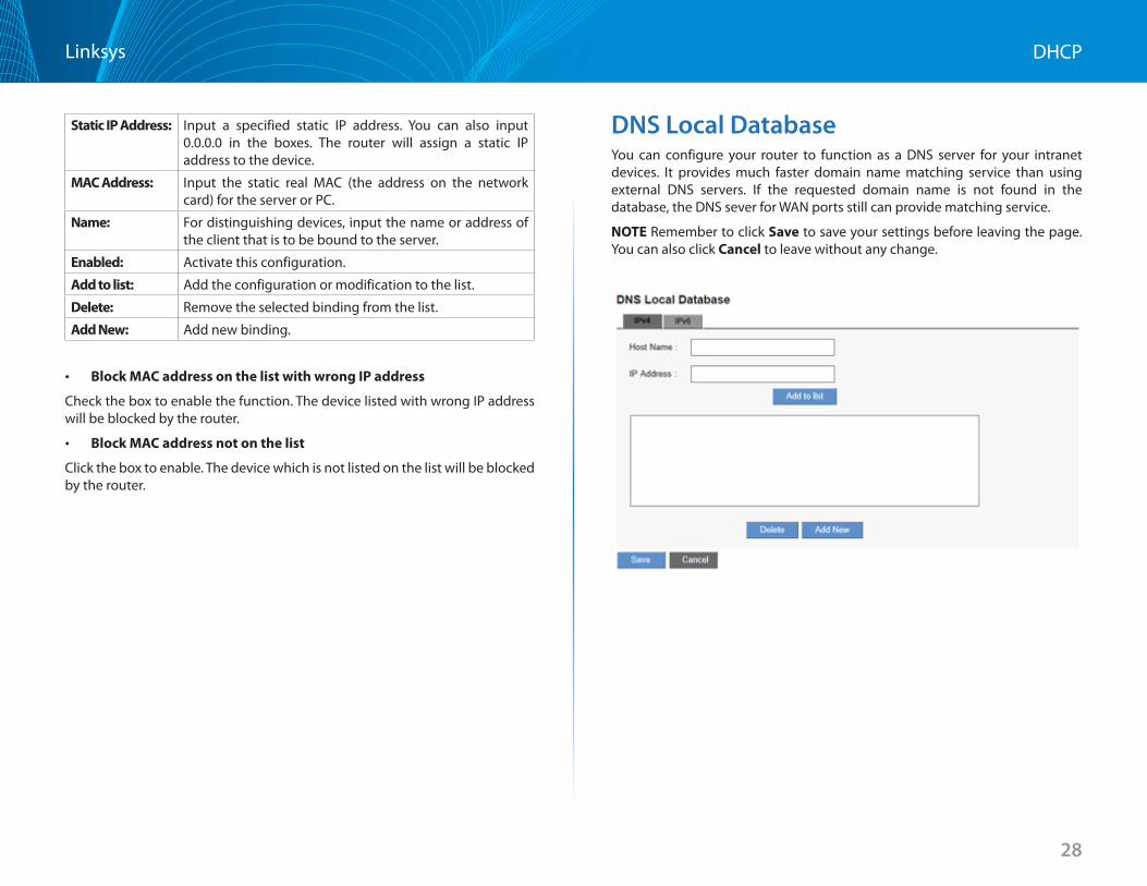
Static IP Address: Input a specified static IP address . You can also input 0 .0 .0 .0 in the boxes . The router will assign a static IP address to the device .
MAC Address: Input the static real MAC (the address on the network card) for the server or PC .
Name: For distinguishing devices, input the name or address of the client that is to be bound to the server .
Enabled: Activate this configuration .
Add to list: Add the configuration or modification to the list .
Delete: Remove the selected binding from the list .
Add New: Add new binding .
• Block MAC address on the list with wrong IP address
Check the box to enable the function . The device listed with wrong IP address will be blocked by the router .
• Block MAC address not on the list
Click the box to enable . The device which is not listed on the list will be blocked by the router .
DNS Local DatabaseYou can configure your router to function as a DNS server for your intranet devices . It provides much faster domain name matching service than using external DNS servers . If the requested domain name is not found in the database, the DNS sever for WAN ports still can provide matching service .
NOTE Remember to click Save to save your settings before leaving the page . You can also click Cancel to leave without any change .
29
DHCPLinksys
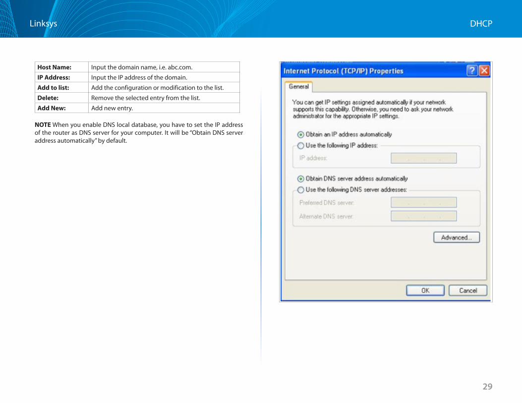
Host Name: Input the domain name, i .e . abc .com .
IP Address: Input the IP address of the domain .
Add to list: Add the configuration or modification to the list .
Delete: Remove the selected entry from the list .
Add New: Add new entry .
NOTE When you enable DNS local database, you have to set the IP address of the router as DNS server for your computer . It will be “Obtain DNS server address automatically” by default .
30
System ManagementLinksys
System Management
You can configure advanced setting in System Management category, please refer to following items:
• DualWAN(LRT224Only)/NetworkServiceDetection
• BandwidthManagement
• SNMP
• SSLCertificate
Dual WAN (LRT224 Only) / Network Service Detection
Dual WANYou can choose Link Failover or Load Balance mode when you use Dual WAN setting . Go to Configuration > System Management > Dual WAN .
NOTE Remember to click Save before leaving the page . You can also click Cancel to undo the changes .
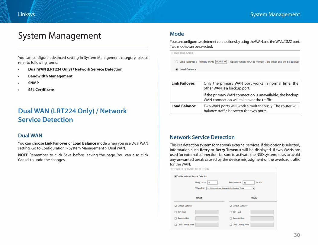
ModeYou can configure two Internet connections by using the WAN and the WAN/DMZ port . Two modes can be selected:
Link Failover: Only the primary WAN port works in normal time; the other WAN is a backup port .
If the primary WAN connection is unavailable, the backup WAN connection will take over the traffic .
Load Balance: Two WAN ports will work simultaneously . The router will balance traffic between the two ports .
Network Service DetectionThis is a detection system for network external services . If this option is selected, information such Retry or Retry Timeout will be displayed . If two WANs are used for external connection, be sure to activate the NSD system, so as to avoid any unwanted break caused by the device misjudgment of the overload traffic for the WAN .
31
System ManagementLinksys
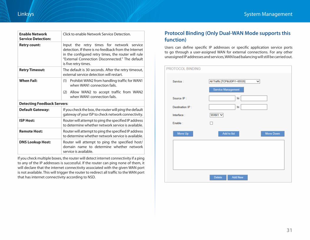
Protocol Binding (Only Dual-WAN Mode supports this function)Users can define specific IP addresses or specific application service ports to go through a user-assigned WAN for external connections. For any other unassigned IP addresses and services, WAN load balancing will still be carried out.
Enable Network Service Detection:
Click to enable Network Service Detection.
Retry count: Input the retry times for network service detection. If there is no feedback from the Internet in the configured retry times, the router will rule “External Connection Disconnected.” The default is five retry times.
Retry Timeout: The default is 30 seconds. After the retry timeout, external service detection will restart.
When Fail: (1) Prohibit WAN2 from handling traffic for WAN1 when WAN1 connection fails.
(2) Allow WAN2 to accept traffic from WAN2 when WAN1 connection fails.
Detecting Feedback Servers:
Default Gateway: If you check the box, the router will ping the default gateway of your ISP to check network connectivity.
ISP Host: Router will attempt to ping the specified IP address to determine whether network service is available.
Remote Host: Router will attempt to ping the specified IP address to determine whether network service is available.
DNS Lookup Host: Router will attempt to ping the specified host/domain name to determine whether network service is available.
If you check multiple boxes, the router will detect internet connectivity if a ping to any of the IP addresses is successful. If the router can ping none of them, it will declare that the internet connectivity associated with the given WAN port is not available. This will trigger the router to redirect all traffic to the WAN port that has internet connectivity according to NSD.
32
System ManagementLinksys
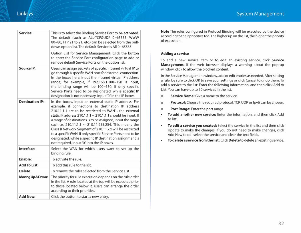
Service: This is to select the Binding Service Port to be activated . The default (such as ALL-TCP&UDP 0~65535, WWW 80~80, FTP 21 to 21, etc .) can be selected from the pull-down option list . The default Service is All 0~65535 .
Option List for Service Management: Click the button to enter the Service Port configuration page to add or remove default Service Ports on the option list .
Source IP: Users can assign packets of specific Intranet virtual IP to go through a specific WAN port for external connection . In the boxes here, input the Intranet virtual IP address range; for example, if 192 .168 .1 .100~150 is input, the binding range will be 100~150 . If only specific Service Ports need to be designated, while specific IP designation is not necessary, input “0” in the IP boxes .
Destination IP: In the boxes, input an external static IP address . For example, if connections to destination IP address 210 .11 .1 .1 are to be restricted to WAN1, the external static IP address 210 .1 .1 .1 ~ 210 .1 .1 .1 should be input . If a range of destinations is to be assigned, input the range such as 210 .11 .1 .1 ~ 210 .11 .255 .254 . This means the Class B Network Segment of 210 .11 .x .x will be restricted to a specific WAN . If only specific Service Ports need to be designated, while a specific IP destination assignment is not required, input “0” into the IP boxes .
Interface: Select the WAN for which users want to set up the binding rule .
Enable: To activate the rule .
Add To List: To add this rule to the list .
Delete To remove the rules selected from the Service List .
Moving Up & Down: The priority for rule execution depends on the rule order in the list . A rule located at the top will be executed prior to those located below it . Users can arrange the order according to their priorities .
Add New: Click the button to start a new entry .
Note The rules configured in Protocol Binding will be executed by the device according to their priorities too . The higher up on the list, the higher the priority of execution .
Adding a service
To add a new service item or to edit an existing service, click Service Management If the web browser displays a warning about the pop-up window, click to allow the blocked content .
In the Service Management window, add or edit entries as needed . After setting a rule, be sure to click OK to save your settings or click Cancel to undo them . To add a service to the list: Enter the following information, and then click Add to List . You can have up to 30 services in the list .
o Service Name: Give a name to the service .
o Protocol: Choose the required protocol . TCP, UDP or Ipv6 can be chosen .
o Port Range: Enter the port range . • To add another new service: Enter the information, and then click Add
to list .
• To edit a service you created: Select the service in the list and then click Update to make the changes . If you do not need to make changes, click Add New to de- select the service and clear the text fields .
• To delete a service from the list : Click Delete to delete an existing service .
33
System ManagementLinksys
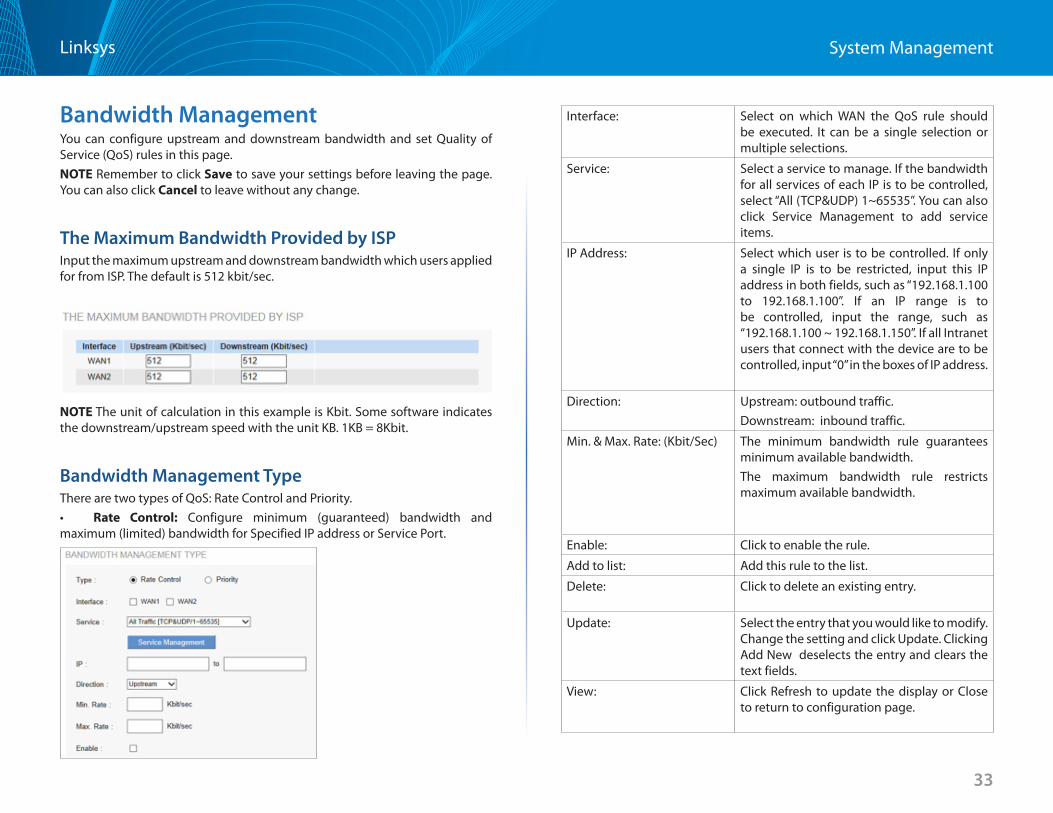
Bandwidth ManagementYou can configure upstream and downstream bandwidth and set Quality of Service (QoS) rules in this page . NOTE Remember to click Save to save your settings before leaving the page . You can also click Cancel to leave without any change .
The Maximum Bandwidth Provided by ISP Input the maximum upstream and downstream bandwidth which users applied for from ISP . The default is 512 kbit/sec .
NOTE The unit of calculation in this example is Kbit . Some software indicates the downstream/upstream speed with the unit KB . 1KB = 8Kbit .
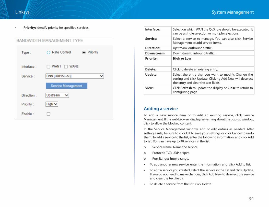
Bandwidth Management Type There are two types of QoS: Rate Control and Priority .• Rate Control: Configure minimum (guaranteed) bandwidth and maximum (limited) bandwidth for Specified IP address or Service Port .
Interface: Select on which WAN the QoS rule should be executed . It can be a single selection or multiple selections .
Service: Select a service to manage . If the bandwidth for all services of each IP is to be controlled, select “All (TCP&UDP) 1~65535” . You can also click Service Management to add service items .
IP Address: Select which user is to be controlled . If only a single IP is to be restricted, input this IP address in both fields, such as “192 .168 .1 .100 to 192 .168 .1 .100” . If an IP range is to be controlled, input the range, such as “192 .168 .1 .100 ~ 192 .168 .1 .150” . If all Intranet users that connect with the device are to be controlled, input “0” in the boxes of IP address .
Direction: Upstream: outbound traffic .Downstream: inbound traffic .
Min . & Max . Rate: (Kbit/Sec) The minimum bandwidth rule guarantees minimum available bandwidth .The maximum bandwidth rule restricts maximum available bandwidth .
Enable: Click to enable the rule .
Add to list: Add this rule to the list .
Delete: Click to delete an existing entry .
Update: Select the entry that you would like to modify . Change the setting and click Update . Clicking Add New deselects the entry and clears the text fields .
View: Click Refresh to update the display or Close to return to configuration page .
34
System ManagementLinksys
• Priority: Identify priority for specified services . Interface: Select on which WAN the QoS rule should be executed . It can be a single selection or multiple selections .
Service: Select a service to manage . You can also click Service Management to add service items .
Direction: Upstream: outbound traffic .
Downstream: Downstream: inbound traffic .
Priority: High or Low
Delete: Click to delete an existing entry .
Update: Select the entry that you want to modify . Change the setting and click Update . Clicking Add New will deselect the entry and clear the text fields .
View: Click Refresh to update the display or Close to return to configuring page .
Adding a service To add a new service item or to edit an existing service, click Service Management . If the web browser displays a warning about the pop-up window, click to allow the blocked content .
In the Service Management window, add or edit entries as needed . After setting a rule, be sure to click OK to save your settings or click Cancel to undo them . To add a service to the list, enter the following information, and click Add to list . You can have up to 30 services in the list .
o Service Name: Name the service .
o Protocol: TCP, UDP or Ipv6 .
o Port Range: Enter a range .
• To add another new service, enter the information, and click Add to list .
• To edit a service you created, select the service in the list and click Update . If you do not need to make changes, click Add New to deselect the service and clear the text fields .
• To delete a service from the list, click Delete .
35
System ManagementLinksys
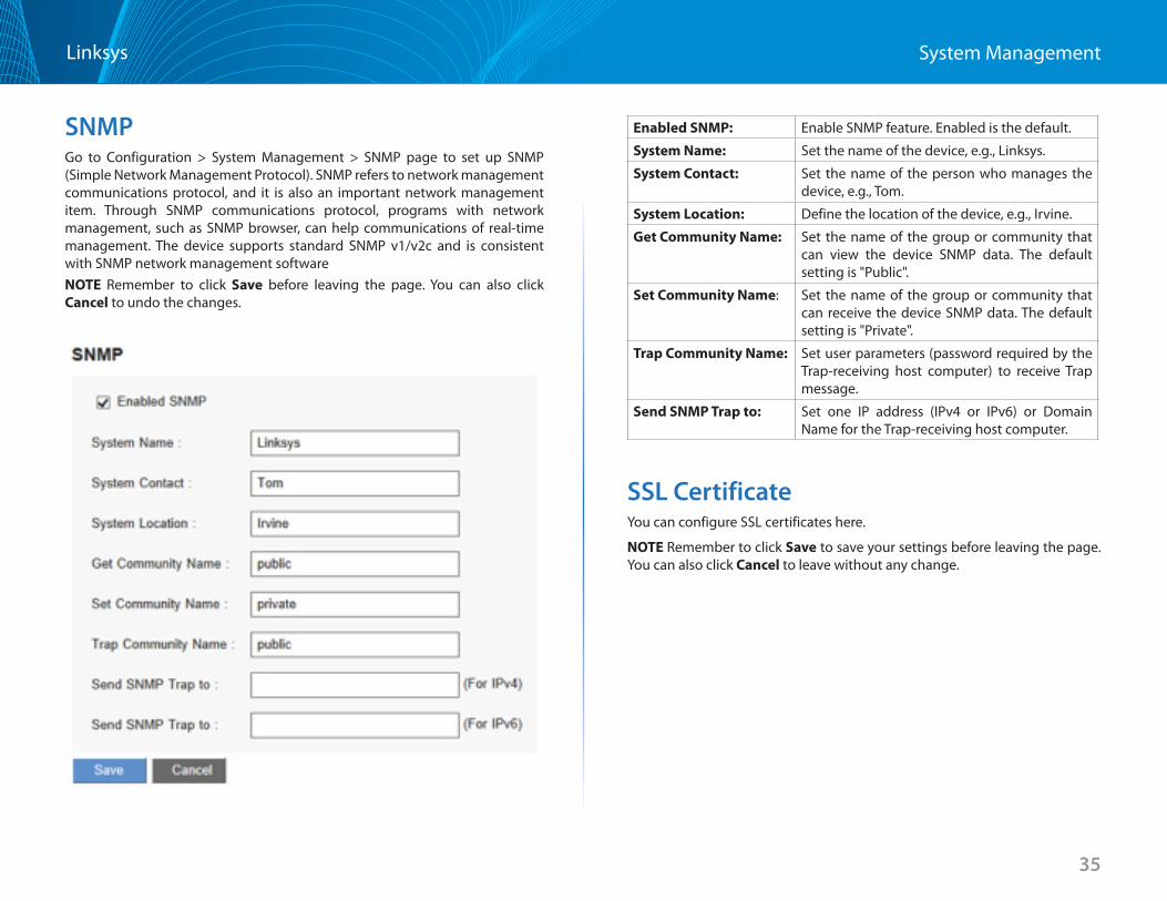
SNMPGo to Configuration > System Management > SNMP page to set up SNMP (Simple Network Management Protocol) . SNMP refers to network management communications protocol, and it is also an important network management item . Through SNMP communications protocol, programs with network management, such as SNMP browser, can help communications of real-time management . The device supports standard SNMP v1/v2c and is consistent with SNMP network management softwareNOTE Remember to click Save before leaving the page . You can also click Cancel to undo the changes .
Enabled SNMP: Enable SNMP feature . Enabled is the default .
System Name: Set the name of the device, e .g ., Linksys .
System Contact: Set the name of the person who manages the device, e .g ., Tom .
System Location: Define the location of the device, e .g ., Irvine .
Get Community Name: Set the name of the group or community that can view the device SNMP data . The default setting is "Public" .
Set Community Name: Set the name of the group or community that can receive the device SNMP data . The default setting is "Private" .
Trap Community Name: Set user parameters (password required by the Trap-receiving host computer) to receive Trap message .
Send SNMP Trap to: Set one IP address (IPv4 or IPv6) or Domain Name for the Trap-receiving host computer .
SSL CertificateYou can configure SSL certificates here .
NOTE Remember to click Save to save your settings before leaving the page . You can also click Cancel to leave without any change .
36
System ManagementLinksys
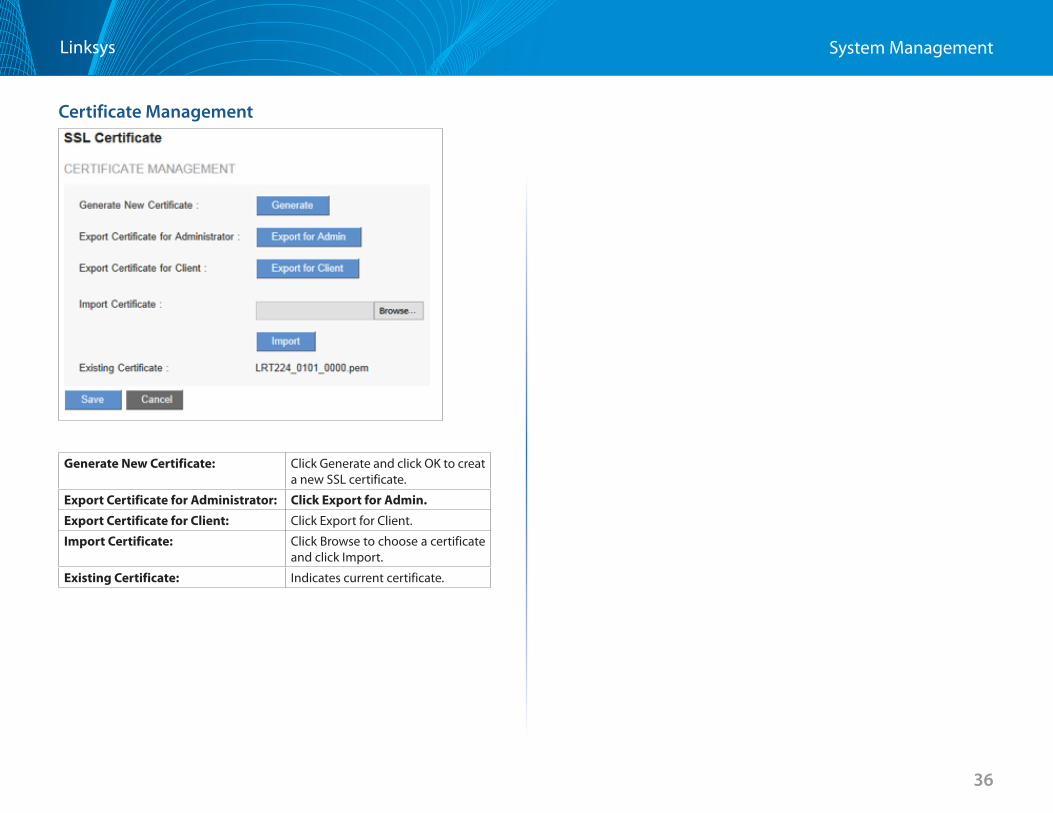
Certificate Management
Generate New Certificate: Click Generate and click OK to creat a new SSL certificate .
Export Certificate for Administrator: Click Export for Admin
Export Certificate for Client: Click Export for Client .
Import Certificate: Click Browse to choose a certificate and click Import .
Existing Certificate: Indicates current certificate .
37
Port ManagementLinksys
37
Port Management
Port Setup
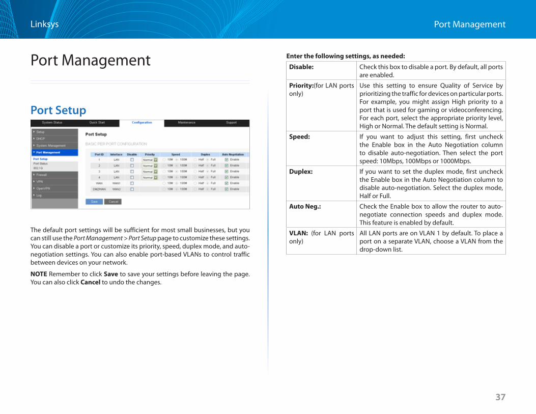
The default port settings will be sufficient for most small businesses, but you can still use the Port Management > Port Setup page to customize these settings . You can disable a port or customize its priority, speed, duplex mode, and auto-negotiation settings . You can also enable port-based VLANs to control traffic between devices on your network .
NOTE Remember to click Save to save your settings before leaving the page . You can also click Cancel to undo the changes .
Enter the following settings, as needed:
Disable: Check this box to disable a port . By default, all ports are enabled .
Priority:(for LAN ports only)
Use this setting to ensure Quality of Service by prioritizing the traffic for devices on particular ports . For example, you might assign High priority to a port that is used for gaming or videoconferencing . For each port, select the appropriate priority level, High or Normal . The default setting is Normal .
Speed: If you want to adjust this setting, first uncheck the Enable box in the Auto Negotiation column to disable auto-negotiation . Then select the port speed: 10Mbps, 100Mbps or 1000Mbps .
Duplex: If you want to set the duplex mode, first uncheck the Enable box in the Auto Negotiation column to disable auto-negotiation . Select the duplex mode, Half or Full .
Auto Neg : Check the Enable box to allow the router to auto-negotiate connection speeds and duplex mode . This feature is enabled by default .
VLAN: (for LAN ports only)
All LAN ports are on VLAN 1 by default . To place a port on a separate VLAN, choose a VLAN from the drop-down list .
38
Port ManagementLinksys
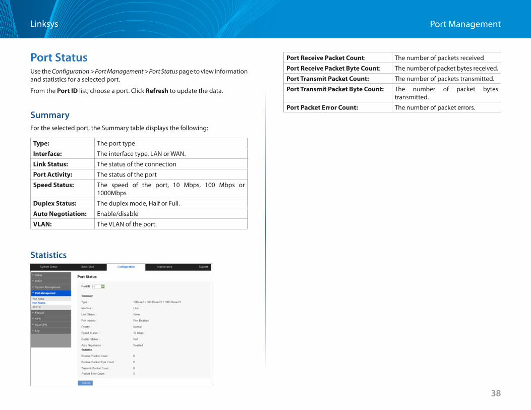
Port StatusUse the Configuration > Port Management > Port Status page to view information and statistics for a selected port .
From the Port ID list, choose a port . Click Refresh to update the data .
SummaryFor the selected port, the Summary table displays the following:
Type: The port type
Interface: The interface type, LAN or WAN .
Link Status: The status of the connection
Port Activity: The status of the port
Speed Status: The speed of the port, 10 Mbps, 100 Mbps or 1000Mbps
Duplex Status: The duplex mode, Half or Full .
Auto Negotiation: Enable/disable
VLAN: The VLAN of the port .
Statistics
Port Receive Packet Count: The number of packets received
Port Receive Packet Byte Count: The number of packet bytes received .
Port Transmit Packet Count: The number of packets transmitted .
Port Transmit Packet Byte Count: The number of packet bytes transmitted .
Port Packet Error Count: The number of packet errors .
39
Port ManagementLinksys
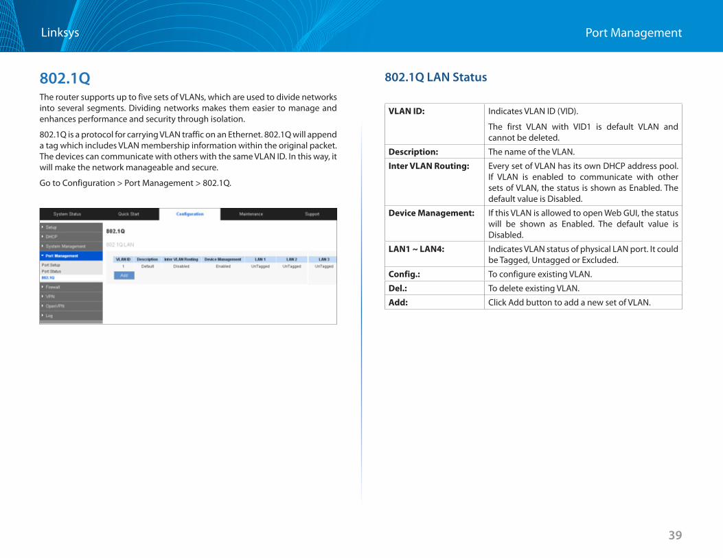
802.1QThe router supports up to five sets of VLANs, which are used to divide networks into several segments . Dividing networks makes them easier to manage and enhances performance and security through isolation .
802 .1Q is a protocol for carrying VLAN traffic on an Ethernet . 802 .1Q will append a tag which includes VLAN membership information within the original packet . The devices can communicate with others with the same VLAN ID . In this way, it will make the network manageable and secure .
Go to Configuration > Port Management > 802 .1Q .
802.1Q LAN Status
VLAN ID: Indicates VLAN ID (VID) .
The first VLAN with VID1 is default VLAN and cannot be deleted .
Description: The name of the VLAN .
Inter VLAN Routing: Every set of VLAN has its own DHCP address pool . If VLAN is enabled to communicate with other sets of VLAN, the status is shown as Enabled . The default value is Disabled .
Device Management: If this VLAN is allowed to open Web GUI, the status will be shown as Enabled . The default value is Disabled .
LAN1 ~ LAN4: Indicates VLAN status of physical LAN port . It could be Tagged, Untagged or Excluded .
Config : To configure existing VLAN .
Del : To delete existing VLAN .
Add: Click Add button to add a new set of VLAN .
40
Port ManagementLinksys
802.1Q LAN ConfigurationYou can click Edit to change an existing VLAN configuration or click Add to set up a new set of VLAN .
VLAN ID: Input VID (range:2~4092) of the VLAN .
Description: Give a name to the VLAN .
Inter VLAN Routing: Every set of VLAN has its own DHCP address pool . Select Enabled so that the VLAN is allowed to communicate with other sets of VLAN . The default value is Disabled .
Device
Management:
Select Enabled to allow the VLAN access to the Web GUI . The default value is Disabled .
LAN1 ~ LAN4: Configure VLAN status of physical LAN ports . There can only be one untagged VID for a LAN port .
For example, if we configure LAN2 as Untagged for VID2, LAN2 for VID1 will be changed as Tagged automatically .
If we configure LAN2 for VID1 as Tagged, LAN2 for VID2 will be changed as Untagged automatically .
If there is only one VID, changing status to Tagged for any LAN port is not allowed .
41
FirewallLinksys
41
Firewall
Firewall General Settings
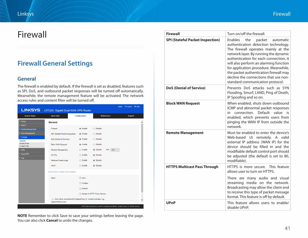
GeneralThe firewall is enabled by default . If the firewall is set as disabled, features such as SPI, DoS, and outbound packet responses will be turned off automatically . Meanwhile, the remote management feature will be activated . The network access rules and content filter will be turned off .
NOTE Remember to click Save to save your settings before leaving the page . You can also click Cancel to undo the changes .
Firewall Turn on/off the firewall .
SPI (Stateful Packet Inspection) Enables the packet automatic authentication detection technology . The firewall operates mainly at the network layer . By running the dynamic authentication for each connection, it will also perform an alarming function for application procedure . Meanwhile, the packet authentication firewall may decline the connections that use non-standard communication protocol .
DoS (Denial of Service) Prevents DoS attacks such as SYN Flooding, Smurf, LAND, Ping of Death, IP Spoofing and so on .
Block WAN Request When enabled, shuts down outbound ICMP and abnormal packet responses in connection . Default value is enabled, which prevents users from pinging the WAN IP from outside the network .
Remote Management Must be enabled to enter the device’s Web-based UI remotely . A valid external IP address (WAN IP) for the device should be filled in and the modifiable default control port should be adjusted (the default is set to 80, modifiable) .
HTTPS Multicast Pass Through HTTPS is more secure . This feature allows user to turn on HTTPS .
There are many audio and visual streaming media on the network . Broadcasting may allow the client end to receive this type of packet message format . This feature is off by default .
UPnP This feature allows users to enable/disable UPnP .
42
FirewallLinksys
Restrict Web FeaturesIt supports the block that is connected through: Java, Cookies, Active X, and HTTP Proxy access .
Don’t Block Java / ActiveX / Cookies Proxy to Trusted Domain
When enabled, users can add trusted network or IP address into the trust domain .
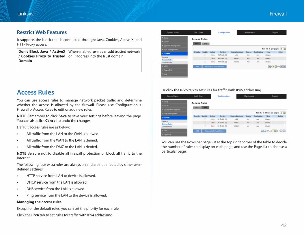
Access RulesYou can use access rules to manage network packet traffic and determine whether the access is allowed by the firewall . Please use Configuration > Firewall > Access Rules to edit or add new rules .
NOTE Remember to click Save to save your settings before leaving the page . You can also click Cancel to undo the changes .
Default access rules are as below:
• AlltrafficfromtheLANtotheWANisallowed.
• AlltrafficfromtheWANtotheLANisdenied.
• AlltrafficfromtheDMZtotheLANisdenied.
NOTE Be sure not to disable all firewall protection or block all traffic to the Internet .
The following four extra rules are always on and are not affected by other user-defined settings .
• HTTPservicefromLANtodeviceisallowed.
• DHCPservicefromtheLANisallowed.
• DNSservicefromtheLANisallowed.
• PingservicefromtheLANtothedeviceisallowed.
Managing the access rules
Except for the default rules, you can set the priority for each rule .
Click the IPv4 tab to set rules for traffic with IPv4 addressing .
Or click the IPv6 tab to set rules for traffic with IPv6 addressing .
You can use the Rows per page list at the top right corner of the table to decide the number of rules to display on each page, and use the Page list to choose a particular page .
43
FirewallLinksys
Priority Indicates the priority of the access rule; 1 being the highest . Select an option from the drop-down list to change the priority . The default access rules have the lowest priority .
Enable A new rule will be automatically assigned with a priority . You can change the priority by editing .
To add a new rule Check the Enable box to enable or uncheck to disable . The default rules are not allowed to change .
To edit a custom rule Click Edit .
To delete an existing rule
Click Delete and click OK to continue, or click Cancel to close the message without deleting the rule .
Return to Default Rules
Click Restore to Default Rules to delete all the self-defined settings .
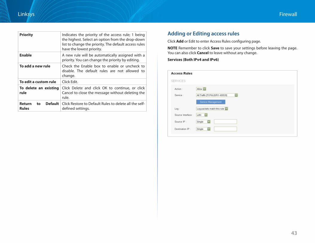
Adding or Editing access rulesClick Add or Edit to enter Access Rules configuring page .
NOTE Remember to click Save to save your settings before leaving the page . You can also click Cancel to leave without any change .
Services (Both IPv4 and IPv6)
44
FirewallLinksys
Action: Allow: Permits the pass of packets compliant with this control rule .Deny: Prevents the pass of packets not compliant with this control rule .
Service: Choose the service for this rule . You can also click Service Management to add new services .
Log: Not Log: There will be no log record .Log packets match this rule: Events will be recorded in the log .
Source Interface: Choose the source interface that is affected by this rule .
Source IP: Identify the traffic source that is affected by this rule . Choose one of the following options from drop-down list: • ANY: This rule applies to any IP address . • Single: This rule applies to a single IP address . Enter
the IP address in the following box . • Range: This rule applies to a range of IP addresses
(IPv4 only) . Enter the first IP address in the first box, and then enter the final IP address in the second box .
• Subnet: This rule applies to a subnetwork (IPv6 only) . Enter the IP address and the prefix length .
Dest IP: Identify the traffic destination that is affected by this rule . Choose one of the following options from drop-down list: • ANY: This rule applies to any IP address . • Single: This rule applies to a single IP address . Enter
the IP address in the following box . • Range: This rule applies to a range of IP addresses
(IPv4 only) . Enter the first IP address in the first box, and then enter the final IP address in the second box .
• Subnet: This rule applies to a subnet (IPv6 only) . Enter the IP address and the prefix length .
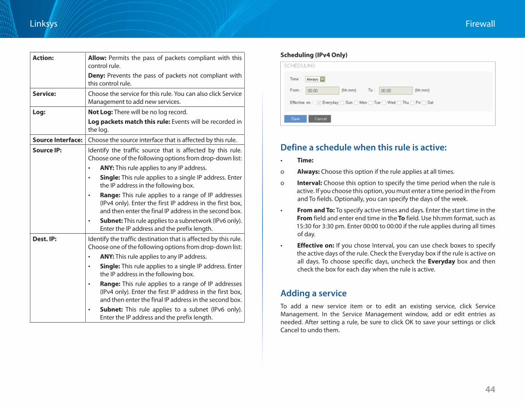
Scheduling (IPv4 Only)
Define a schedule when this rule is active:• Time:
o Always: Choose this option if the rule applies at all times .
o Interval: Choose this option to specify the time period when the rule is active . If you choose this option, you must enter a time period in the From and To fields . Optionally, you can specify the days of the week .
• From and To: To specify active times and days . Enter the start time in the From field and enter end time in the To field . Use hh:mm format, such as 15:30 for 3:30 pm . Enter 00:00 to 00:00 if the rule applies during all times of day .
• Effective on: If you chose Interval, you can use check boxes to specify the active days of the rule . Check the Everyday box if the rule is active on all days . To choose specific days, uncheck the Everyday box and then check the box for each day when the rule is active .
Adding a serviceTo add a new service item or to edit an existing service, click Service Management . In the Service Management window, add or edit entries as needed . After setting a rule, be sure to click OK to save your settings or click Cancel to undo them .
45
FirewallLinksys
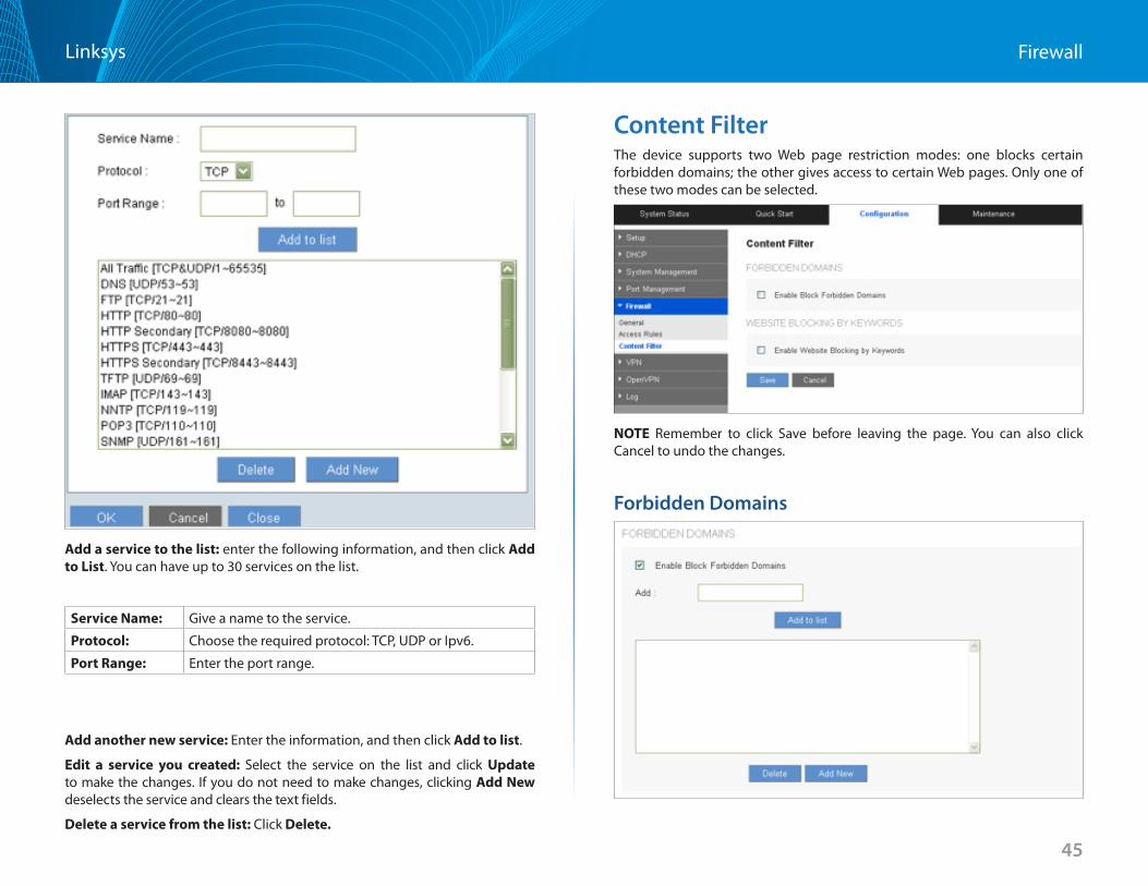
Add a service to the list: enter the following information, and then click Add to List . You can have up to 30 services on the list .
Service Name: Give a name to the service .
Protocol: Choose the required protocol: TCP, UDP or Ipv6 .
Port Range: Enter the port range .
Add another new service: Enter the information, and then click Add to list .
Edit a service you created: Select the service on the list and click Update to make the changes . If you do not need to make changes, clicking Add New deselects the service and clears the text fields .
Delete a service from the list: Click Delete
Content FilterThe device supports two Web page restriction modes: one blocks certain forbidden domains; the other gives access to certain Web pages . Only one of these two modes can be selected .
NOTE Remember to click Save before leaving the page . You can also click Cancel to undo the changes .
Forbidden Domains
46
FirewallLinksys
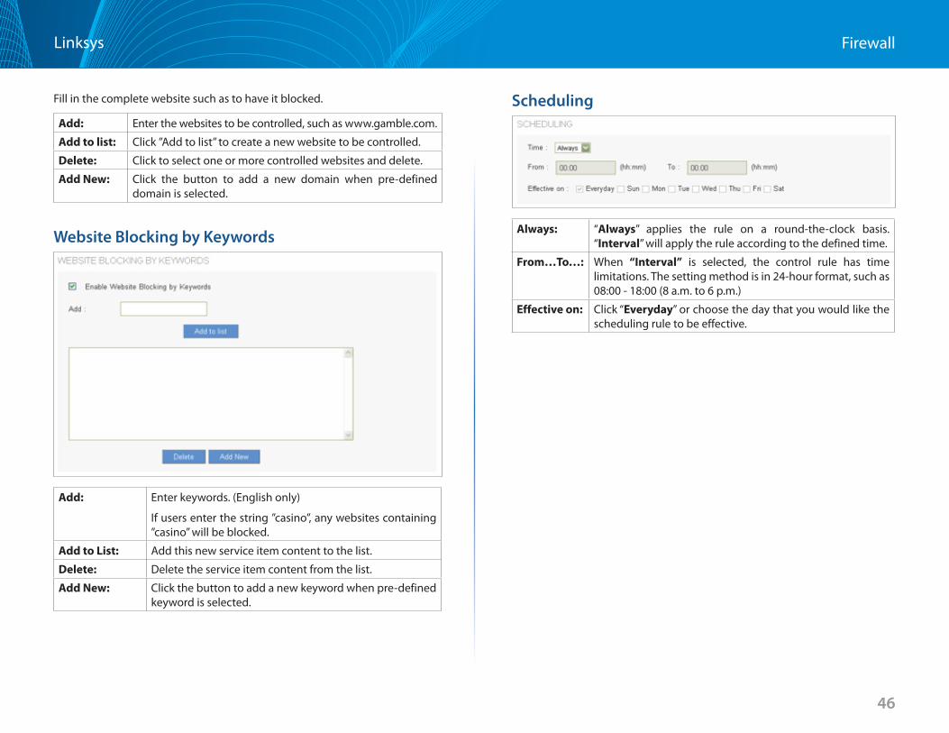
Fill in the complete website such as to have it blocked .
Add: Enter the websites to be controlled, such as www .gamble .com .
Add to list: Click ”Add to list” to create a new website to be controlled .
Delete: Click to select one or more controlled websites and delete .
Add New: Click the button to add a new domain when pre-defined domain is selected .
Website Blocking by Keywords
Add: Enter keywords . (English only)
If users enter the string ”casino”, any websites containing ”casino” will be blocked .
Add to List: Add this new service item content to the list .
Delete: Delete the service item content from the list .
Add New: Click the button to add a new keyword when pre-defined keyword is selected .
Scheduling
Always: “Always” applies the rule on a round-the-clock basis . “Interval” will apply the rule according to the defined time .
From…To…: When “Interval” is selected, the control rule has time limitations . The setting method is in 24-hour format, such as 08:00 - 18:00 (8 a .m . to 6 p .m .)
Effective on: Click “Everyday” or choose the day that you would like the scheduling rule to be effective .

47
VPNLinksys
47
VPN
VPN (Virtual Private Network) is a technology that enables two private networks to establish a secure and encrypted connection across public network, such as the Internet . VPN allows remote user, say a branch office or employee at home, to access the company intranet and share files, video conference or access servers, i .e ., ERP or mail server .
The router provides several VPN protocols . You can choose which kinds of VPN technology are most suitable for your network structure and using scenarios .
SummaryThe Summary page features details on the current status of VPN tunnel . The router supports up to 50 tunnels .
NOTE Summary information about PPTP only appears when you enable the PPTP server .
Summary
Tunnel(s) Used: The number of VPN tunnels in use .
Tunnels Available: The total number of VPN tunnels the router will support .
Detail: Click Refresh to update the data, or click Close to return to summary page .
Tunnel Status
Tunnel(s) Enabled: How many tunnels are enabled by the administrator .
Tunnel(s) Defined: How many tunnels are defined by the administrator: enabled and disabled .
The table displays the following information about each tunnel:
No : Indicates the number of the tunnel .
Name: VPN tunnel connection name, such as XXX OfficeGive the tunnels different names to avoid confusion if you have more than one tunnel connected .
Status: Connected or Waiting for Connection .
Phase2
Encrypt/
Auth/Group:
Displays settings such as Encryption type (NULL/DES/3DES/ AES-128/AES-192/AES-256), Authentication method (NULL/MD5/SHA1), and DH Group number (1/2/5)
If users select Manual setting for IPSec, Phase 2 DH group will not display .
Local Group: Settings for local VPN connection secure group .
Remote
Group:
Settings for remote VPN connection secure group .
Remote
Gateway:
The IP address of the Remote Gateway .
Tunnel Test: Click “Connect” to verify the tunnel status . The test result will be updated . To disconnect, click “Disconnect” to stop the VPN connection . To delete tunnel settings, select a tunnel, and then click the Delete icon .
Config : Setting icons include Edit and Delete . Click on Edit to change settings . Click Delete to remove all tunnel settings .
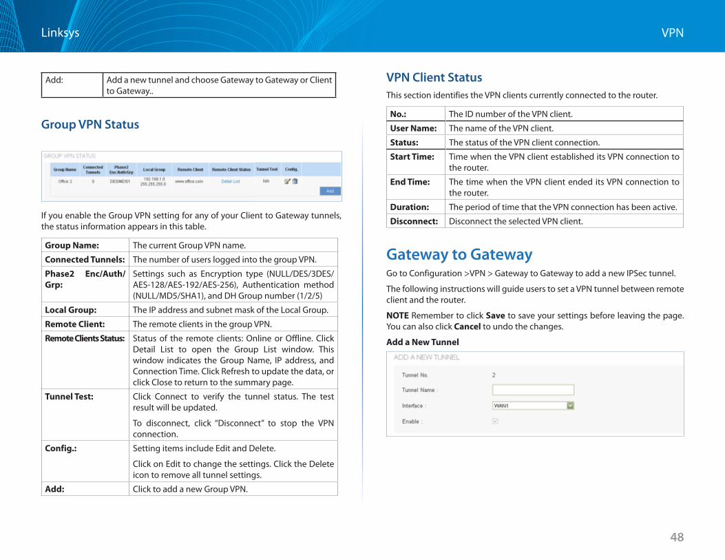
48
VPNLinksys
Add: Add a new tunnel and choose Gateway to Gateway or Client to Gateway . .
Group VPN Status
If you enable the Group VPN setting for any of your Client to Gateway tunnels, the status information appears in this table .
Group Name: The current Group VPN name .
Connected Tunnels: The number of users logged into the group VPN .
Phase2 Enc/Auth/Grp:
Settings such as Encryption type (NULL/DES/3DES/ AES-128/AES-192/AES-256), Authentication method (NULL/MD5/SHA1), and DH Group number (1/2/5)
Local Group: The IP address and subnet mask of the Local Group .
Remote Client: The remote clients in the group VPN .
Remote Clients Status: Status of the remote clients: Online or Offline . Click Detail List to open the Group List window . This window indicates the Group Name, IP address, and Connection Time . Click Refresh to update the data, or click Close to return to the summary page .
Tunnel Test: Click Connect to verify the tunnel status . The test result will be updated .
To disconnect, click “Disconnect” to stop the VPN connection .
Config : Setting items include Edit and Delete .
Click on Edit to change the settings . Click the Delete icon to remove all tunnel settings .
Add: Click to add a new Group VPN .
VPN Client StatusThis section identifies the VPN clients currently connected to the router .
No : The ID number of the VPN client .
User Name: The name of the VPN client .
Status: The status of the VPN client connection .
Start Time: Time when the VPN client established its VPN connection to the router .
End Time: The time when the VPN client ended its VPN connection to the router .
Duration: The period of time that the VPN connection has been active .
Disconnect: Disconnect the selected VPN client .
Gateway to Gateway Go to Configuration >VPN > Gateway to Gateway to add a new IPSec tunnel .
The following instructions will guide users to set a VPN tunnel between remote client and the router .
NOTE Remember to click Save to save your settings before leaving the page . You can also click Cancel to undo the changes .
Add a New Tunnel
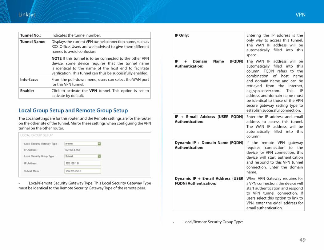
49
VPNLinksys
Tunnel No : Indicates the tunnel number .
Tunnel Name: Displays the current VPN tunnel connection name, such as XXX Office . Users are well-advised to give them different names to avoid confusion .
NOTE If this tunnel is to be connected to the other VPN device, some device requires that the tunnel name is identical to the name of the host end to facilitate verification . This tunnel can thus be successfully enabled .
Interface: From the pull-down menu, users can select the WAN port for this VPN tunnel .
Enable: Click to activate the VPN tunnel . This option is set to activate by default .
Local Group Setup and Remote Group Setup The Local settings are for this router, and the Remote settings are for the router on the other site of the tunnel . Mirror these settings when configuring the VPN tunnel on the other router .
• Local/RemoteSecurityGatewayType:ThisLocalSecurityGatewayTypemust be identical to the Remote Security Gateway Type of the remote peer .
IP Only: Entering the IP address is the only way to access this tunnel . The WAN IP address will be automatically filled into this space .
IP + Domain Name (FQDN) Authentication:
The WAN IP address will be automatically filled into this column . FQDN refers to the combination of host name and domain name and can be retrieved from the Internet, e .g .,vpn .server .com . This IP address and domain name must be identical to those of the VPN secure gateway setting type to establish successful connection .
IP + E-mail Address (USER FQDN)Authentication:
Enter the IP address and email address to access this tunnel . The WAN IP address will be automatically filled into this column .
Dynamic IP + Domain Name (FQDN) Authentication:
If the remote VPN gateway requires connection to the device for VPN connection, this device will start authentication and respond to this VPN tunnel connection . Enter the domain name .
Dynamic IP + E-mail Address (USERFQDN) Authentication:
When VPN Gateway requires for a VPN connection, the device will start authentication and respond to VPN tunnel connection . If users select this option to link to VPN, enter the eMail address for email authentication .
• Local/RemoteSecurityGroupType:
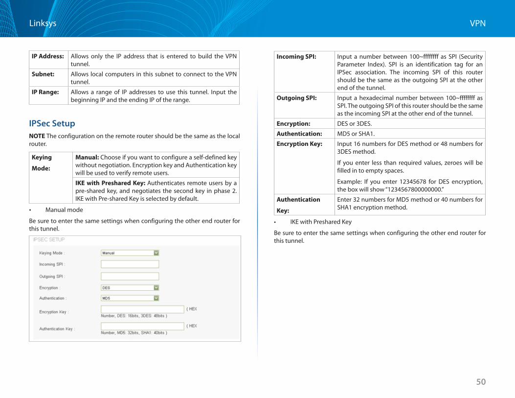
50
VPNLinksys
IP Address: Allows only the IP address that is entered to build the VPN tunnel .
Subnet: Allows local computers in this subnet to connect to the VPN tunnel .
IP Range: Allows a range of IP addresses to use this tunnel . Input the beginning IP and the ending IP of the range .
IPSec SetupNOTE The configuration on the remote router should be the same as the local router .
Keying
Mode:
Manual: Choose if you want to configure a self-defined key without negotiation . Encryption key and Authentication key will be used to verify remote users .
IKE with Preshared Key: Authenticates remote users by a pre-shared key, and negotiates the second key in phase 2 . IKE with Pre-shared Key is selected by default .
• Manual mode
Be sure to enter the same settings when configuring the other end router for this tunnel .
Incoming SPI: Input a number between 100~ffffffff as SPI (Security Parameter Index) . SPI is an identification tag for an IPSec association . The incoming SPI of this router should be the same as the outgoing SPI at the other end of the tunnel .
Outgoing SPI: Input a hexadecimal number between 100~ffffffff as SPI . The outgoing SPI of this router should be the same as the incoming SPI at the other end of the tunnel .
Encryption: DES or 3DES .
Authentication: MD5 or SHA1 .
Encryption Key: Input 16 numbers for DES method or 48 numbers for 3DES method .
If you enter less than required values, zeroes will be filled in to empty spaces .
Example: If you enter 12345678 for DES encryption, the box will show “1234567800000000 .”
Authentication
Key:
Enter 32 numbers for MD5 method or 40 numbers for SHA1 encryption method .
• IKEwithPresharedKey
Be sure to enter the same settings when configuring the other end router for this tunnel .
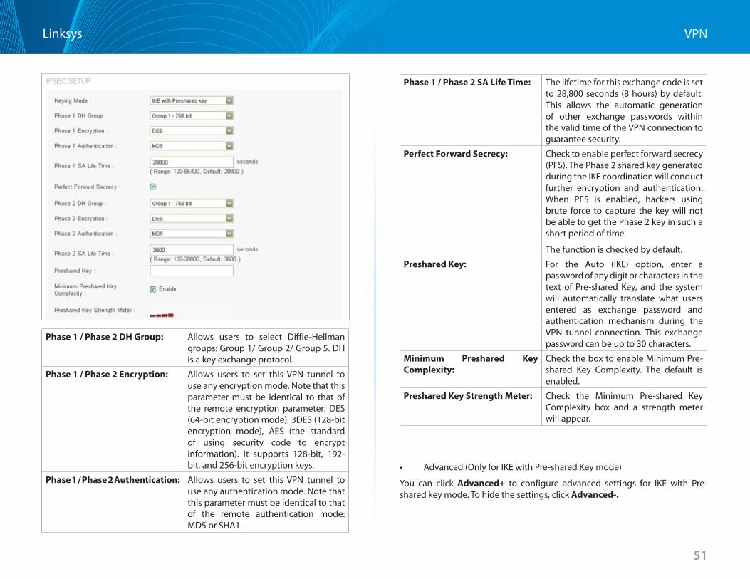
51
VPNLinksys
Phase 1 / Phase 2 DH Group: Allows users to select Diffie-Hellman groups: Group 1/ Group 2/ Group 5 . DH is a key exchange protocol .
Phase 1 / Phase 2 Encryption: Allows users to set this VPN tunnel to use any encryption mode . Note that this parameter must be identical to that of the remote encryption parameter: DES (64-bit encryption mode), 3DES (128-bit encryption mode), AES (the standard of using security code to encrypt information) . It supports 128-bit, 192-bit, and 256-bit encryption keys .
Phase 1 / Phase 2 Authentication: Allows users to set this VPN tunnel to use any authentication mode . Note that this parameter must be identical to that of the remote authentication mode: MD5 or SHA1 .
Phase 1 / Phase 2 SA Life Time: The lifetime for this exchange code is set to 28,800 seconds (8 hours) by default . This allows the automatic generation of other exchange passwords within the valid time of the VPN connection to guarantee security .
Perfect Forward Secrecy: Check to enable perfect forward secrecy (PFS) . The Phase 2 shared key generated during the IKE coordination will conduct further encryption and authentication . When PFS is enabled, hackers using brute force to capture the key will not be able to get the Phase 2 key in such a short period of time .
The function is checked by default .
Preshared Key: For the Auto (IKE) option, enter a password of any digit or characters in the text of Pre-shared Key, and the system will automatically translate what users entered as exchange password and authentication mechanism during the VPN tunnel connection . This exchange password can be up to 30 characters .
Minimum Preshared Key Complexity:
Check the box to enable Minimum Pre-shared Key Complexity . The default is enabled .
Preshared Key Strength Meter: Check the Minimum Pre-shared Key Complexity box and a strength meter will appear .
• Advanced(OnlyforIKEwithPre-sharedKeymode)
You can click Advanced+ to configure advanced settings for IKE with Pre-shared key mode . To hide the settings, click Advanced-.
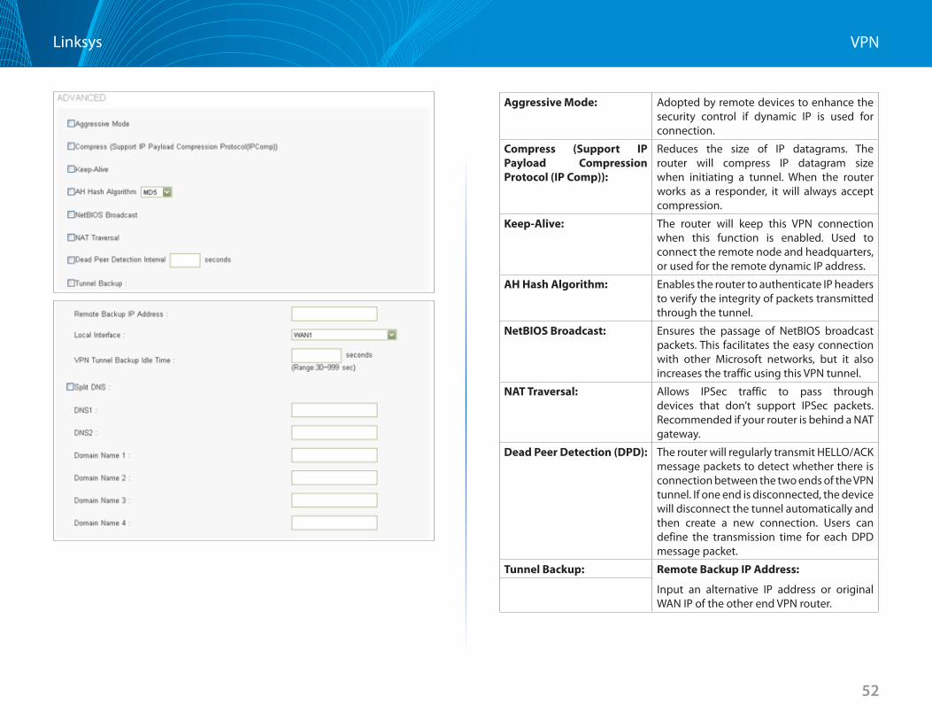
52
VPNLinksys
Aggressive Mode: Adopted by remote devices to enhance the security control if dynamic IP is used for connection .
Compress (Support IP Payload Compression Protocol (IP Comp)):
Reduces the size of IP datagrams . The router will compress IP datagram size when initiating a tunnel . When the router works as a responder, it will always accept compression .
Keep-Alive: The router will keep this VPN connection when this function is enabled . Used to connect the remote node and headquarters, or used for the remote dynamic IP address .
AH Hash Algorithm: Enables the router to authenticate IP headers to verify the integrity of packets transmitted through the tunnel .
NetBIOS Broadcast: Ensures the passage of NetBIOS broadcast packets . This facilitates the easy connection with other Microsoft networks, but it also increases the traffic using this VPN tunnel .
NAT Traversal: Allows IPSec traffic to pass through devices that don’t support IPSec packets . Recommended if your router is behind a NAT gateway .
Dead Peer Detection (DPD): The router will regularly transmit HELLO/ACK message packets to detect whether there is connection between the two ends of the VPN tunnel . If one end is disconnected, the device will disconnect the tunnel automatically and then create a new connection . Users can define the transmission time for each DPD message packet .
Tunnel Backup: Remote Backup IP Address:
Input an alternative IP address or original WAN IP of the other end VPN router .
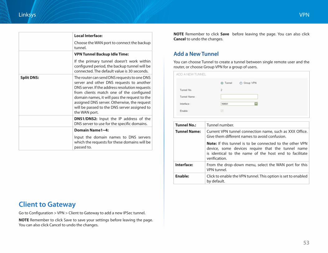
53
VPNLinksys
Local Interface:
Choose the WAN port to connect the backup tunnel .
VPN Tunnel Backup Idle Time:
If the primary tunnel doesn’t work within configured period, the backup tunnel will be connected . The default value is 30 seconds .
Split DNS: The router can send DNS requests to one DNS server and other DNS requests to another DNS server . If the address resolution requests from clients match one of the configured domain names, it will pass the request to the assigned DNS server . Otherwise, the request will be passed to the DNS server assigned to the WAN port .
DNS1/DNS2: Input the IP address of the DNS server to use for the specific domains .
Domain Name1~4:
Input the domain names to DNS servers which the requests for these domains will be passed to .
Client to Gateway Go to Configuration > VPN > Client to Gateway to add a new IPSec tunnel .
NOTE Remember to click Save to save your settings before leaving the page . You can also click Cancel to undo the changes .
NOTE Remember to click Save before leaving the page . You can also click Cancel to undo the changes .
Add a New Tunnel You can choose Tunnel to create a tunnel between single remote user and the router, or choose Group VPN for a group of users .
Tunnel No : Tunnel number .
Tunnel Name: Current VPN tunnel connection name, such as XXX Office . Give them different names to avoid confusion .
Note: If this tunnel is to be connected to the other VPN device, some devices require that the tunnel name is identical to the name of the host end to facilitate verification .
Interface: From the drop-down menu, select the WAN port for this VPN tunnel .
Enable: Click to enable the VPN tunnel . This option is set to enabled by default .
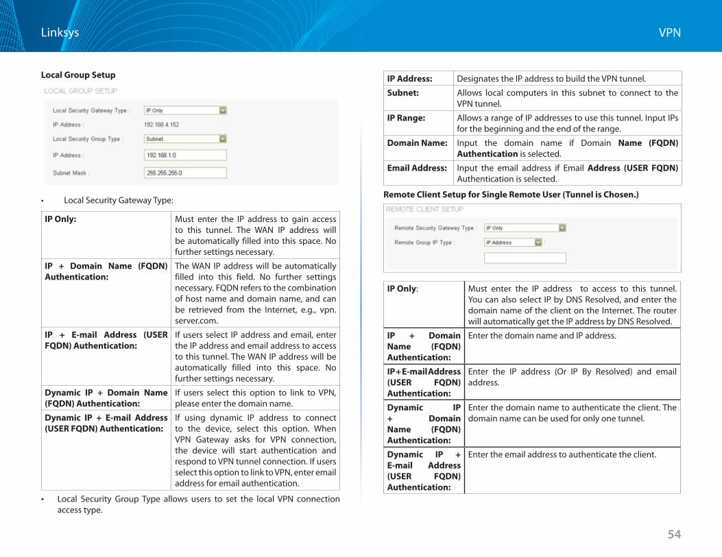
54
VPNLinksys
Local Group Setup
• LocalSecurityGatewayType:
IP Only: Must enter the IP address to gain access to this tunnel . The WAN IP address will be automatically filled into this space . No further settings necessary .
IP + Domain Name (FQDN) Authentication:
The WAN IP address will be automatically filled into this field . No further settings necessary . FQDN refers to the combination of host name and domain name, and can be retrieved from the Internet, e .g ., vpn .server .com .
IP + E-mail Address (USERFQDN) Authentication:
If users select IP address and email, enter the IP address and email address to access to this tunnel . The WAN IP address will be automatically filled into this space . No further settings necessary .
Dynamic IP + Domain Name (FQDN) Authentication:
If users select this option to link to VPN, please enter the domain name .
Dynamic IP + E-mail Address(USER FQDN) Authentication:
If using dynamic IP address to connect to the device, select this option . When VPN Gateway asks for VPN connection, the device will start authentication and respond to VPN tunnel connection . If users select this option to link to VPN, enter email address for email authentication .
• Local Security Group Type allows users to set the local VPN connection access type .
IP Address: Designates the IP address to build the VPN tunnel .
Subnet: Allows local computers in this subnet to connect to the VPN tunnel .
IP Range: Allows a range of IP addresses to use this tunnel . Input IPs for the beginning and the end of the range .
Domain Name: Input the domain name if Domain Name (FQDN) Authentication is selected .
Email Address: Input the email address if Email Address (USER FQDN) Authentication is selected .
Remote Client Setup for Single Remote User (Tunnel is Chosen )
IP Only: Must enter the IP address to access to this tunnel . You can also select IP by DNS Resolved, and enter the domain name of the client on the Internet . The router will automatically get the IP address by DNS Resolved .
IP + Domain Name (FQDN) Authentication:
Enter the domain name and IP address .
IP+E-mailAddress(USER FQDN) Authentication:
Enter the IP address (Or IP By Resolved) and email address .
Dynamic IP + Domain Name (FQDN) Authentication:
Enter the domain name to authenticate the client . The domain name can be used for only one tunnel .
Dynamic IP + E-mail Address(USER FQDN) Authentication:
Enter the email address to authenticate the client .
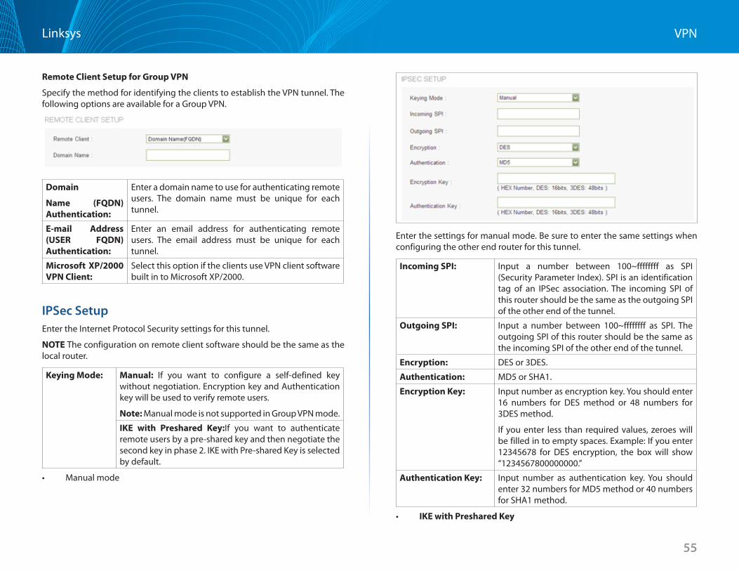
55
VPNLinksys
Remote Client Setup for Group VPN
Specify the method for identifying the clients to establish the VPN tunnel . The following options are available for a Group VPN .
Domain
Name (FQDN) Authentication:
Enter a domain name to use for authenticating remote users . The domain name must be unique for each tunnel .
E-mail Address(USER FQDN) Authentication:
Enter an email address for authenticating remote users . The email address must be unique for each tunnel .
Microsoft XP/2000 VPN Client:
Select this option if the clients use VPN client software built in to Microsoft XP/2000 .
IPSec SetupEnter the Internet Protocol Security settings for this tunnel .
NOTE The configuration on remote client software should be the same as the local router .
Keying Mode: Manual: If you want to configure a self-defined key without negotiation . Encryption key and Authentication key will be used to verify remote users .
Note: Manual mode is not supported in Group VPN mode .
IKE with Preshared Key:If you want to authenticate remote users by a pre-shared key and then negotiate the second key in phase 2 . IKE with Pre-shared Key is selected by default .
• Manualmode
Enter the settings for manual mode . Be sure to enter the same settings when configuring the other end router for this tunnel .
Incoming SPI: Input a number between 100~ffffffff as SPI (Security Parameter Index) . SPI is an identification tag of an IPSec association . The incoming SPI of this router should be the same as the outgoing SPI of the other end of the tunnel .
Outgoing SPI: Input a number between 100~ffffffff as SPI . The outgoing SPI of this router should be the same as the incoming SPI of the other end of the tunnel .
Encryption: DES or 3DES .
Authentication: MD5 or SHA1 .
Encryption Key: Input number as encryption key . You should enter 16 numbers for DES method or 48 numbers for 3DES method .
If you enter less than required values, zeroes will be filled in to empty spaces . Example: If you enter 12345678 for DES encryption, the box will show “1234567800000000 .”
Authentication Key: Input number as authentication key . You should enter 32 numbers for MD5 method or 40 numbers for SHA1 method .
• IKE with Preshared Key
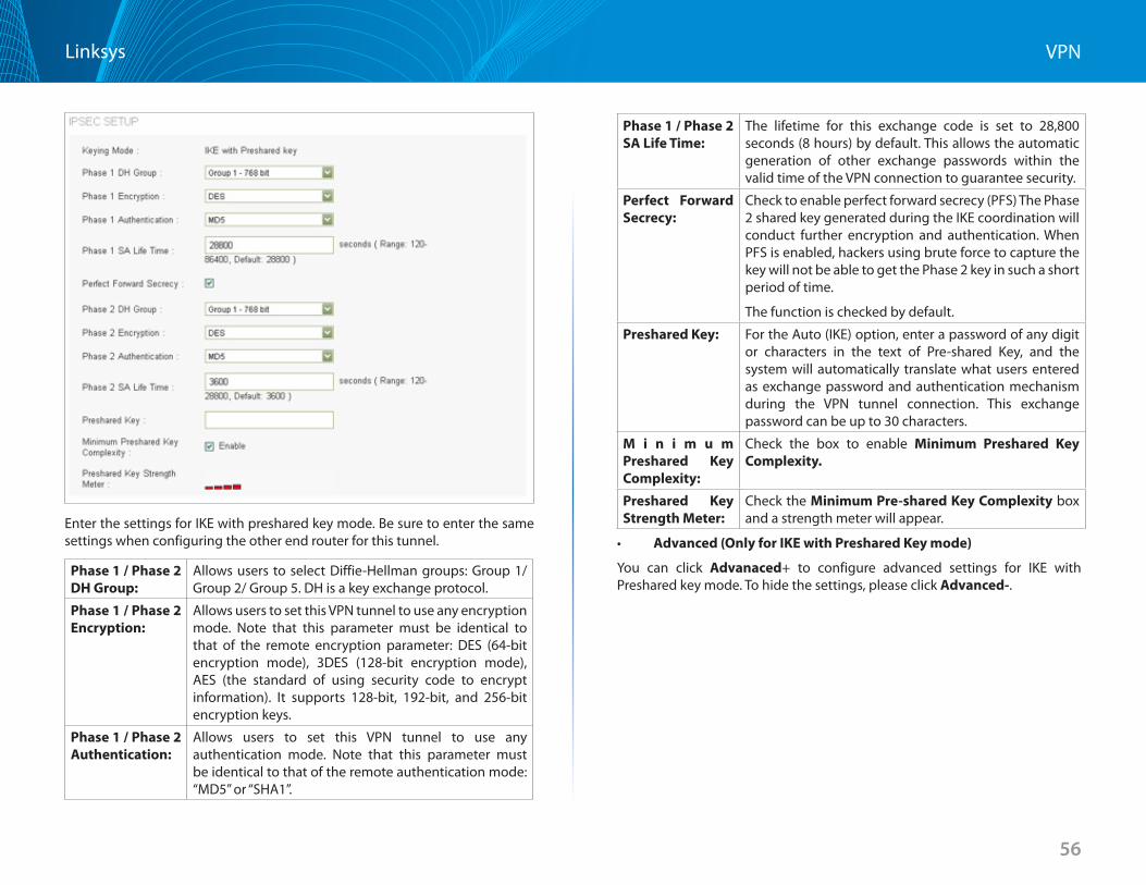
56
VPNLinksys
Enter the settings for IKE with preshared key mode . Be sure to enter the same settings when configuring the other end router for this tunnel .
Phase 1 / Phase 2 DH Group:
Allows users to select Diffie-Hellman groups: Group 1/ Group 2/ Group 5 . DH is a key exchange protocol .
Phase 1 / Phase 2 Encryption:
Allows users to set this VPN tunnel to use any encryption mode . Note that this parameter must be identical to that of the remote encryption parameter: DES (64-bit encryption mode), 3DES (128-bit encryption mode), AES (the standard of using security code to encrypt information) . It supports 128-bit, 192-bit, and 256-bit encryption keys .
Phase 1 / Phase 2 Authentication:
Allows users to set this VPN tunnel to use any authentication mode . Note that this parameter must be identical to that of the remote authentication mode: “MD5” or “SHA1” .
Phase 1 / Phase 2 SA Life Time:
The lifetime for this exchange code is set to 28,800 seconds (8 hours) by default . This allows the automatic generation of other exchange passwords within the valid time of the VPN connection to guarantee security .
Perfect Forward Secrecy:
Check to enable perfect forward secrecy (PFS) The Phase 2 shared key generated during the IKE coordination will conduct further encryption and authentication . When PFS is enabled, hackers using brute force to capture the key will not be able to get the Phase 2 key in such a short period of time .
The function is checked by default .
Preshared Key: For the Auto (IKE) option, enter a password of any digit or characters in the text of Pre-shared Key, and the system will automatically translate what users entered as exchange password and authentication mechanism during the VPN tunnel connection . This exchange password can be up to 30 characters .
M i n i m u m Preshared Key Complexity:
Check the box to enable Minimum Preshared Key Complexity
Preshared Key Strength Meter:
Check the MinimumPre-sharedKeyComplexity box and a strength meter will appear .
• Advanced (Only for IKE with Preshared Key mode)
You can click Advanaced+ to configure advanced settings for IKE with Preshared key mode . To hide the settings, please click Advanced- .
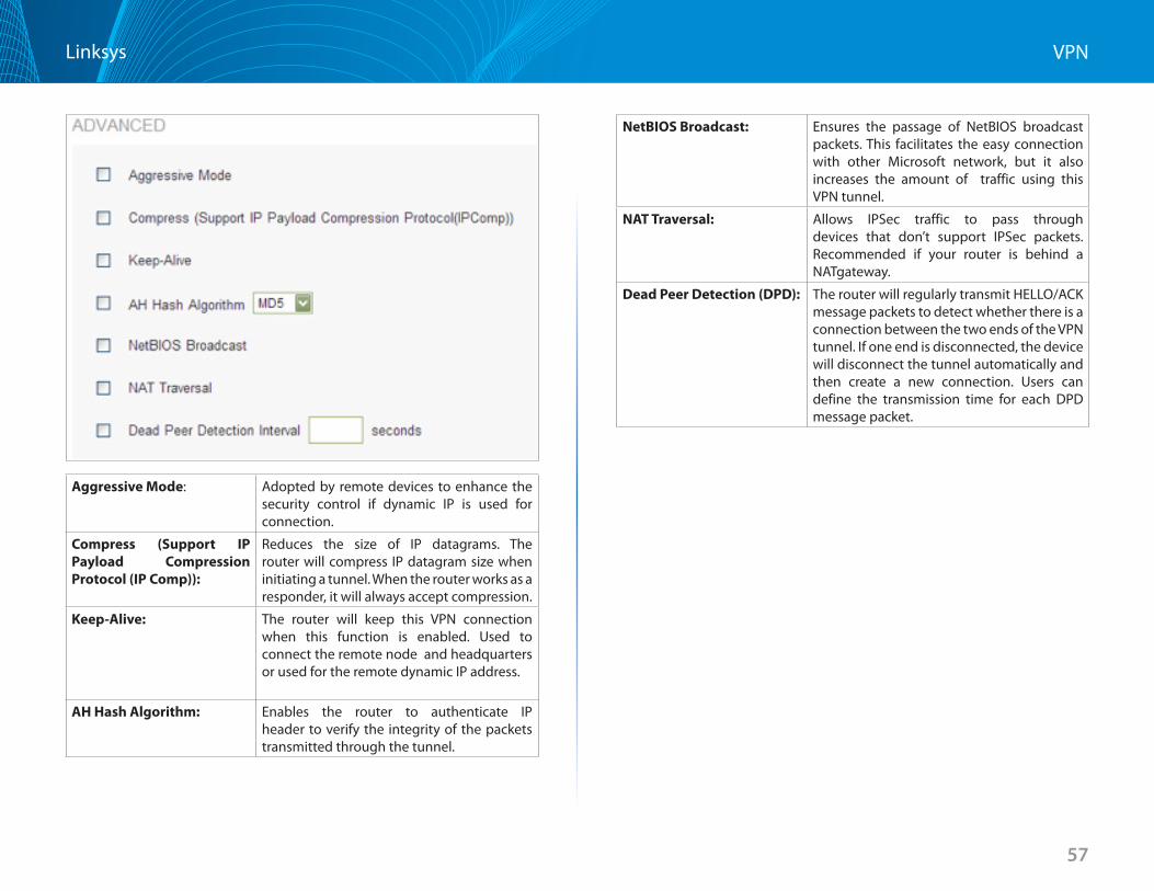
57
VPNLinksys
Aggressive Mode: Adopted by remote devices to enhance the security control if dynamic IP is used for connection .
Compress (Support IP Payload Compression Protocol (IP Comp)):
Reduces the size of IP datagrams . The router will compress IP datagram size when initiating a tunnel . When the router works as a responder, it will always accept compression .
Keep-Alive: The router will keep this VPN connection when this function is enabled . Used to connect the remote node and headquarters or used for the remote dynamic IP address .
AH Hash Algorithm: Enables the router to authenticate IP header to verify the integrity of the packets transmitted through the tunnel .
NetBIOS Broadcast: Ensures the passage of NetBIOS broadcast packets . This facilitates the easy connection with other Microsoft network, but it also increases the amount of traffic using this VPN tunnel .
NAT Traversal: Allows IPSec traffic to pass through devices that don’t support IPSec packets . Recommended if your router is behind a NATgateway .
Dead Peer Detection (DPD): The router will regularly transmit HELLO/ACK message packets to detect whether there is a connection between the two ends of the VPN tunnel . If one end is disconnected, the device will disconnect the tunnel automatically and then create a new connection . Users can define the transmission time for each DPD message packet .
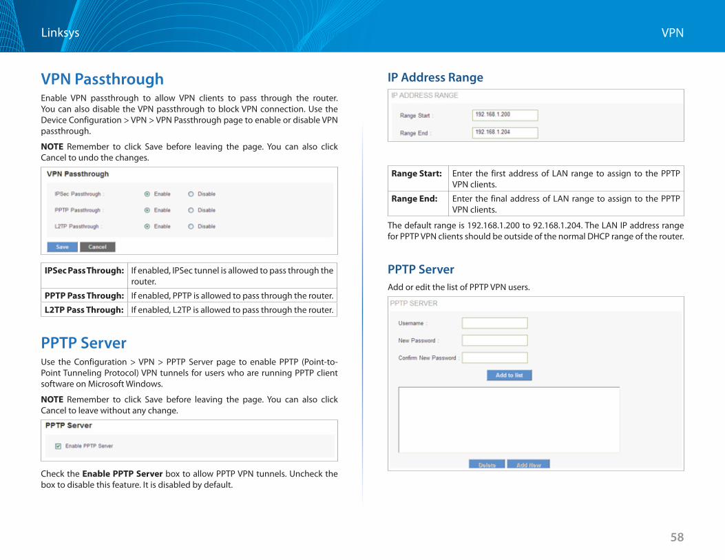
58
VPNLinksys
VPN Passthrough Enable VPN passthrough to allow VPN clients to pass through the router . You can also disable the VPN passthrough to block VPN connection . Use the Device Configuration > VPN > VPN Passthrough page to enable or disable VPN passthrough .
NOTE Remember to click Save before leaving the page . You can also click Cancel to undo the changes .
IPSec Pass Through: If enabled, IPSec tunnel is allowed to pass through the router .
PPTP Pass Through: If enabled, PPTP is allowed to pass through the router .
L2TP Pass Through: If enabled, L2TP is allowed to pass through the router .
PPTP Server Use the Configuration > VPN > PPTP Server page to enable PPTP (Point-to-Point Tunneling Protocol) VPN tunnels for users who are running PPTP client software on Microsoft Windows .
NOTE Remember to click Save before leaving the page . You can also click Cancel to leave without any change .
Check the Enable PPTP Server box to allow PPTP VPN tunnels . Uncheck the box to disable this feature . It is disabled by default .
IP Address Range
Range Start: Enter the first address of LAN range to assign to the PPTP VPN clients .
Range End: Enter the final address of LAN range to assign to the PPTP VPN clients .
The default range is 192 .168 .1 .200 to 92 .168 .1 .204 . The LAN IP address range for PPTP VPN clients should be outside of the normal DHCP range of the router .
PPTP Server Add or edit the list of PPTP VPN users .
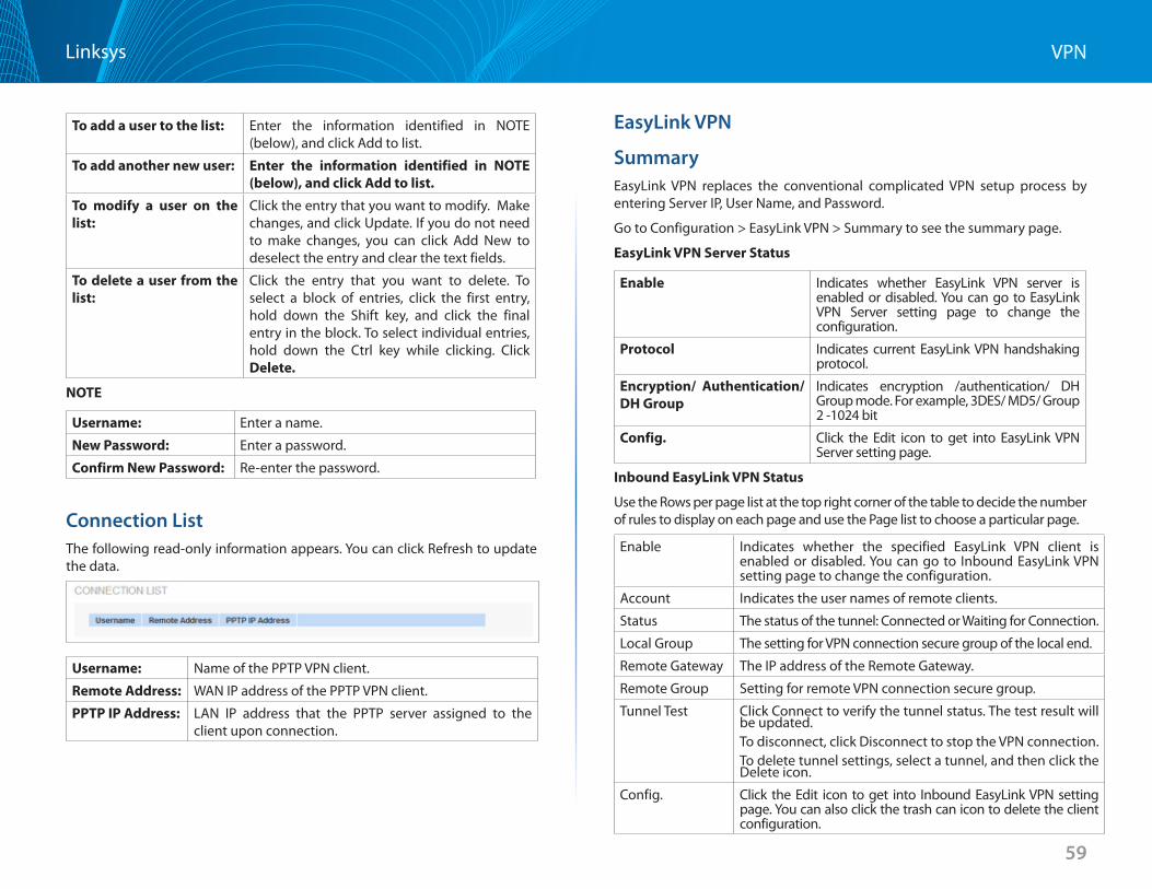
59
VPNLinksys
To add a user to the list: Enter the information identified in NOTE (below), and click Add to list .
To add another new user: Enter the information identified in NOTE (below), and click Add to list
To modify a user on the list:
Click the entry that you want to modify . Make changes, and click Update . If you do not need to make changes, you can click Add New to deselect the entry and clear the text fields .
To delete a user from the list:
Click the entry that you want to delete . To select a block of entries, click the first entry, hold down the Shift key, and click the final entry in the block . To select individual entries, hold down the Ctrl key while clicking . Click Delete
NOTE
Username: Enter a name .
New Password: Enter a password .
Confirm New Password: Re-enter the password .
Connection ListThe following read-only information appears . You can click Refresh to update the data .
Username: Name of the PPTP VPN client .
Remote Address: WAN IP address of the PPTP VPN client .
PPTP IP Address: LAN IP address that the PPTP server assigned to the client upon connection .
EasyLink VPN
SummaryEasyLink VPN replaces the conventional complicated VPN setup process by entering Server IP, User Name, and Password .
Go to Configuration > EasyLink VPN > Summary to see the summary page .
EasyLink VPN Server Status
Enable Indicates whether EasyLink VPN server is enabled or disabled . You can go to EasyLink VPN Server setting page to change the configuration .
Protocol Indicates current EasyLink VPN handshaking protocol .
Encryption/ Authentication/ DH Group
Indicates encryption /authentication/ DH Group mode . For example, 3DES/ MD5/ Group 2 -1024 bit
Config Click the Edit icon to get into EasyLink VPN Server setting page .
Inbound EasyLink VPN Status
Use the Rows per page list at the top right corner of the table to decide the number of rules to display on each page and use the Page list to choose a particular page .
Enable Indicates whether the specified EasyLink VPN client is enabled or disabled . You can go to Inbound EasyLink VPN setting page to change the configuration .
Account Indicates the user names of remote clients .
Status The status of the tunnel: Connected or Waiting for Connection .
Local Group The setting for VPN connection secure group of the local end .
Remote Gateway The IP address of the Remote Gateway .
Remote Group Setting for remote VPN connection secure group .
Tunnel Test Click Connect to verify the tunnel status . The test result will be updated . To disconnect, click Disconnect to stop the VPN connection .To delete tunnel settings, select a tunnel, and then click the Delete icon .
Config . Click the Edit icon to get into Inbound EasyLink VPN setting page . You can also click the trash can icon to delete the client configuration .
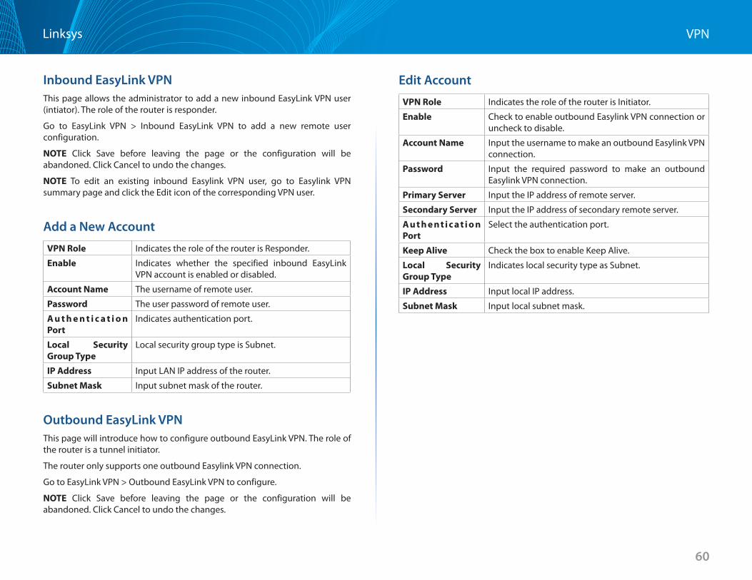
60
VPNLinksys
Inbound EasyLink VPNThis page allows the administrator to add a new inbound EasyLink VPN user (intiator) . The role of the router is responder .
Go to EasyLink VPN > Inbound EasyLink VPN to add a new remote user configuration .
NOTE Click Save before leaving the page or the configuration will be abandoned . Click Cancel to undo the changes .
NOTE To edit an existing inbound Easylink VPN user, go to Easylink VPN summary page and click the Edit icon of the corresponding VPN user .
Add a New Account
VPN Role Indicates the role of the router is Responder .
Enable Indicates whether the specified inbound EasyLink VPN account is enabled or disabled .
Account Name The username of remote user .
Password The user password of remote user .
Au t h e n t i c a t i o n Port
Indicates authentication port .
Local Security Group Type
Local security group type is Subnet .
IP Address Input LAN IP address of the router .
Subnet Mask Input subnet mask of the router .
Outbound EasyLink VPNThis page will introduce how to configure outbound EasyLink VPN . The role of the router is a tunnel initiator .
The router only supports one outbound Easylink VPN connection .
Go to EasyLink VPN > Outbound EasyLink VPN to configure .
NOTE Click Save before leaving the page or the configuration will be abandoned . Click Cancel to undo the changes .
Edit Account
VPN Role Indicates the role of the router is Initiator .
Enable Check to enable outbound Easylink VPN connection or uncheck to disable .
Account Name Input the username to make an outbound Easylink VPN connection .
Password Input the required password to make an outbound Easylink VPN connection .
Primary Server Input the IP address of remote server .
Secondary Server Input the IP address of secondary remote server .
Authent icat ion Port
Select the authentication port .
Keep Alive Check the box to enable Keep Alive .
Local Security Group Type
Indicates local security type as Subnet .
IP Address Input local IP address .
Subnet Mask Input local subnet mask .
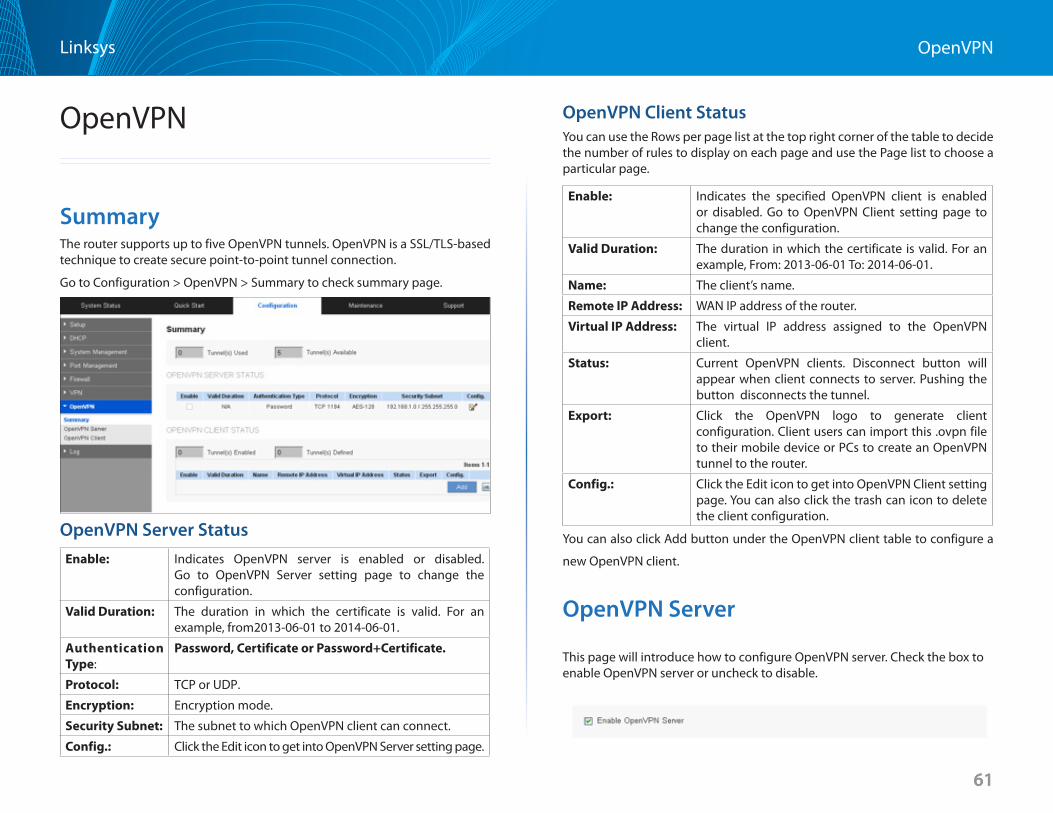
61
OpenVPNLinksys
61
OpenVPN
SummaryThe router supports up to five OpenVPN tunnels . OpenVPN is a SSL/TLS-based technique to create secure point-to-point tunnel connection .
Go to Configuration > OpenVPN > Summary to check summary page .
OpenVPN Server StatusEnable: Indicates OpenVPN server is enabled or disabled .
Go to OpenVPN Server setting page to change the configuration .
Valid Duration: The duration in which the certificate is valid . For an example, from2013-06-01 to 2014-06-01 .
Authentication Type:
Password, Certificate or Password+Certificate
Protocol: TCP or UDP .
Encryption: Encryption mode .
Security Subnet: The subnet to which OpenVPN client can connect .
Config : Click the Edit icon to get into OpenVPN Server setting page .
OpenVPN Client StatusYou can use the Rows per page list at the top right corner of the table to decide the number of rules to display on each page and use the Page list to choose a particular page .
Enable: Indicates the specified OpenVPN client is enabled or disabled . Go to OpenVPN Client setting page to change the configuration .
Valid Duration: The duration in which the certificate is valid . For an example, From: 2013-06-01 To: 2014-06-01 .
Name: The client’s name .
Remote IP Address: WAN IP address of the router .
Virtual IP Address: The virtual IP address assigned to the OpenVPN client .
Status: Current OpenVPN clients . Disconnect button will appear when client connects to server . Pushing the button disconnects the tunnel .
Export: Click the OpenVPN logo to generate client configuration . Client users can import this .ovpn file to their mobile device or PCs to create an OpenVPN tunnel to the router .
Config : Click the Edit icon to get into OpenVPN Client setting page . You can also click the trash can icon to delete the client configuration .
You can also click Add button under the OpenVPN client table to configure a
new OpenVPN client .
OpenVPN Server
This page will introduce how to configure OpenVPN server . Check the box to enable OpenVPN server or uncheck to disable .
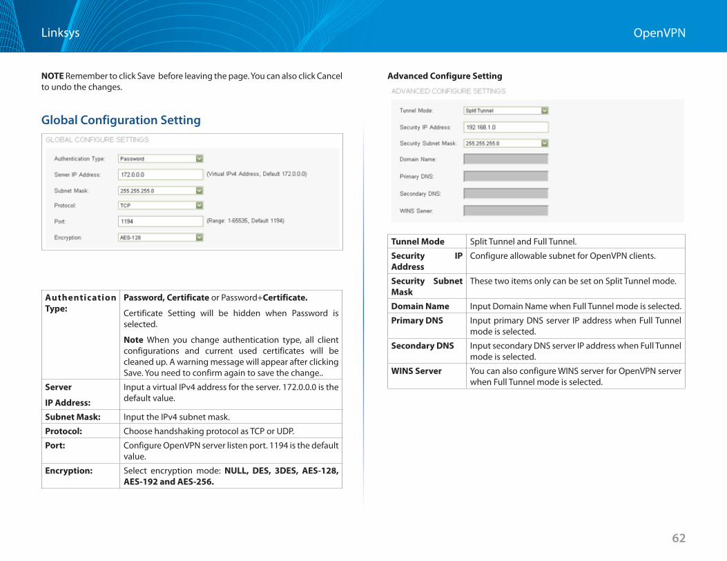
62
OpenVPNLinksys
NOTE Remember to click Save before leaving the page . You can also click Cancel to undo the changes .
Global Configuration Setting
Authentication Type:
Password, Certificate or Password+Certificate
Certificate Setting will be hidden when Password is selected .
Note When you change authentication type, all client configurations and current used certificates will be cleaned up . A warning message will appear after clicking Save . You need to confirm again to save the change . .
Server
IP Address:
Input a virtual IPv4 address for the server . 172 .0 .0 .0 is the default value .
Subnet Mask: Input the IPv4 subnet mask .
Protocol: Choose handshaking protocol as TCP or UDP .
Port: Configure OpenVPN server listen port . 1194 is the default value .
Encryption: Select encryption mode: NULL, DES, 3DES, AES-128,AES-192andAES-256.
Advanced Configure Setting
Tunnel Mode Split Tunnel and Full Tunnel .
Security IP Address
Configure allowable subnet for OpenVPN clients .
Security Subnet Mask
These two items only can be set on Split Tunnel mode .
Domain Name Input Domain Name when Full Tunnel mode is selected .
Primary DNS Input primary DNS server IP address when Full Tunnel mode is selected .
Secondary DNS Input secondary DNS server IP address when Full Tunnel mode is selected .
WINS Server You can also configure WINS server for OpenVPN server when Full Tunnel mode is selected .
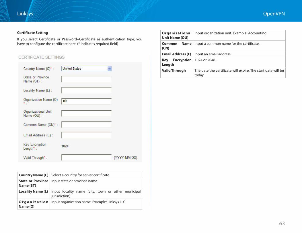
63
OpenVPNLinksys
Certificate Setting
If you select Certificate or Password+Certificate as authentication type, you have to configure the certificate here . (* indicates required field)
Country Name (C) Select a country for server certificate .
State or Province Name (ST)
Input state or province name .
Locality Name (L) Input locality name (city, town or other municipal jurisdiction) .
O r g a n i z a t i o n Name (O)
Input organization name . Example: Linksys LLC .
Organizational Unit Name (OU)
Input organization unit . Example: Accounting .
Common Name (CN)
Input a common name for the certificate .
Email Address (E) Input an email address .
Key Encryption Length
1024 or 2048 .
Valid Through The date the certificate will expire . The start date will be today .
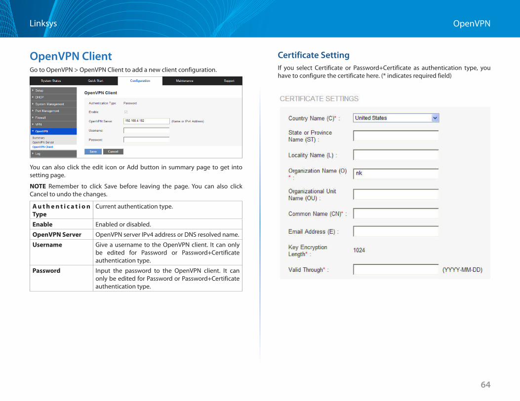
64
OpenVPNLinksys
OpenVPN ClientGo to OpenVPN > OpenVPN Client to add a new client configuration .
You can also click the edit icon or Add button in summary page to get into setting page .
NOTE Remember to click Save before leaving the page . You can also click Cancel to undo the changes .
A u t h e n t i c a t i o n Type
Current authentication type .
Enable Enabled or disabled .
OpenVPN Server OpenVPN server IPv4 address or DNS resolved name .
Username Give a username to the OpenVPN client . It can only be edited for Password or Password+Certificate authentication type .
Password Input the password to the OpenVPN client . It can only be edited for Password or Password+Certificate authentication type .
Certificate SettingIf you select Certificate or Password+Certificate as authentication type, you have to configure the certificate here . (* indicates required field)
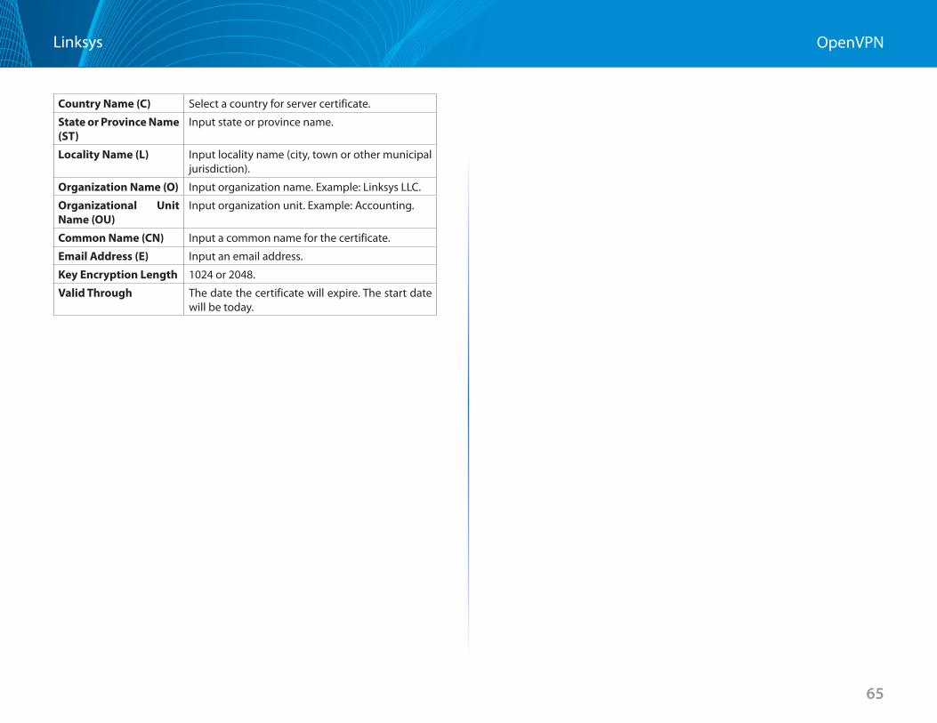
65
OpenVPNLinksys
Country Name (C) Select a country for server certificate .
State or Province Name (ST)
Input state or province name .
Locality Name (L) Input locality name (city, town or other municipal jurisdiction) .
Organization Name (O) Input organization name . Example: Linksys LLC .
Organizational Unit Name (OU)
Input organization unit . Example: Accounting .
Common Name (CN) Input a common name for the certificate .
Email Address (E) Input an email address .
Key Encryption Length 1024 or 2048 .
Valid Through The date the certificate will expire . The start date will be today .
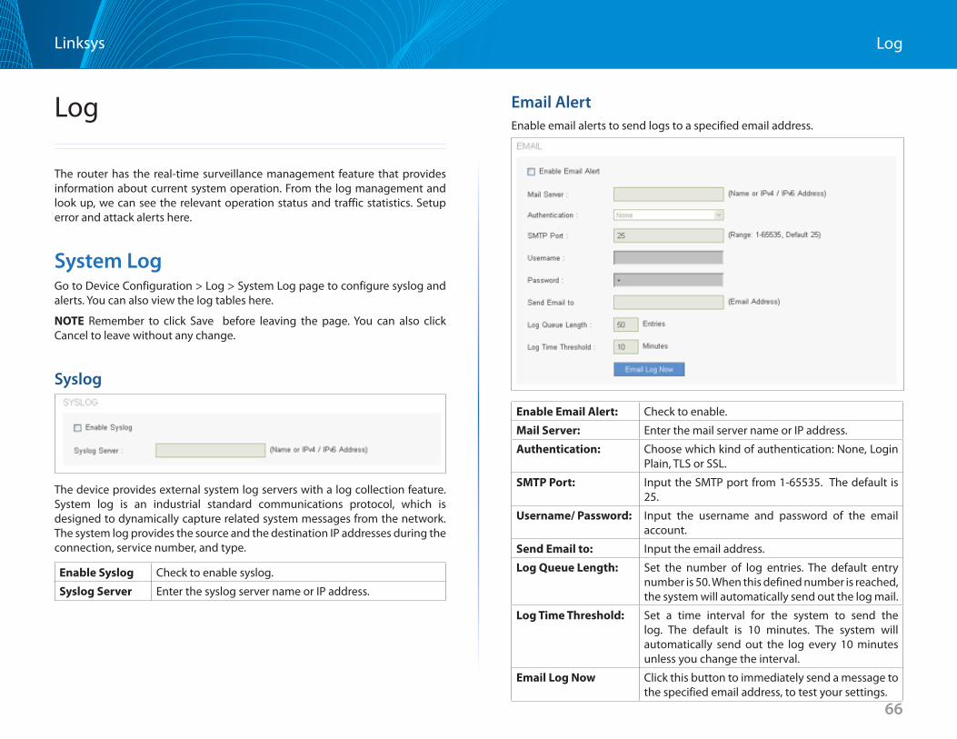
66
LogLinksys
Log
The router has the real-time surveillance management feature that provides information about current system operation . From the log management and look up, we can see the relevant operation status and traffic statistics . Setup error and attack alerts here .
System LogGo to Device Configuration > Log > System Log page to configure syslog and alerts . You can also view the log tables here .
NOTE Remember to click Save before leaving the page . You can also click Cancel to leave without any change .
Syslog
The device provides external system log servers with a log collection feature . System log is an industrial standard communications protocol, which is designed to dynamically capture related system messages from the network . The system log provides the source and the destination IP addresses during the connection, service number, and type .
Enable Syslog Check to enable syslog .
Syslog Server Enter the syslog server name or IP address .
Email AlertEnable email alerts to send logs to a specified email address .
Enable Email Alert: Check to enable .
Mail Server: Enter the mail server name or IP address .
Authentication: Choose which kind of authentication: None, Login Plain, TLS or SSL .
SMTP Port: Input the SMTP port from 1-65535 . The default is 25 .
Username/ Password: Input the username and password of the email account .
Send Email to: Input the email address .
Log Queue Length: Set the number of log entries . The default entry number is 50 . When this defined number is reached, the system will automatically send out the log mail .
Log Time Threshold: Set a time interval for the system to send the log . The default is 10 minutes . The system will automatically send out the log every 10 minutes unless you change the interval .
Email Log Now Click this button to immediately send a message to the specified email address, to test your settings .
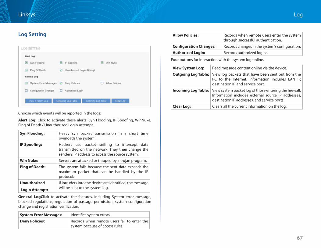
67
LogLinksys
Log Setting
Choose which events will be reported in the logs:
Alert Log: Click to activate these alerts: Syn Flooding, IP Spoofing, WinNuke, Ping of Death / Unauthorized Login Attempt .
Syn Flooding: Heavy syn packet transmission in a short time overloads the system .
IP Spoofing: Hackers use packet sniffing to intercept data transmitted on the network . They then change the sender’s IP address to access the source system .
Win Nuke: Servers are attacked or trapped by a trojan program .
Ping of Death: The system fails because the sent data exceeds the maximum packet that can be handled by the IP protocol .
Unauthorized
Login Attempt:
If intruders into the device are identified, the message will be sent to the system log .
General LogClick to activate the features, including System error message, blocked regulations, regulation of passage permission, system configuration change and registration verification .
System Error Messages: Identifies system errors .
Deny Policies: Records when remote users fail to enter the system because of access rules .
Allow Policies: Records when remote users enter the system through successful authentication .
Configuration Changes: Records changes in the system’s configuration .
Authorized Login: Records authorized logins .
Four buttons for interaction with the system log online .
View System Log: Read message content online via the device .
Outgoing Log Table: View log packets that have been sent out from the PC to the Internet . Information includes LAN IP, destination IP, and service port .
Incoming Log Table: View system packet log of those entering the firewall . Information includes external source IP addresses, destination IP addresses, and service ports .
Clear Log: Clears all the current information on the log .
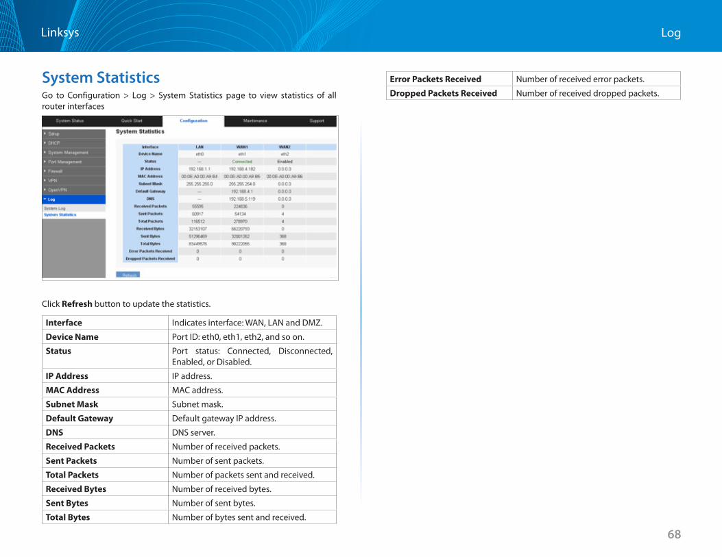
68
LogLinksys
System StatisticsGo to Configuration > Log > System Statistics page to view statistics of all router interfaces
Click Refresh button to update the statistics .
Interface Indicates interface: WAN, LAN and DMZ .
Device Name Port ID: eth0, eth1, eth2, and so on .
Status Port status: Connected, Disconnected, Enabled, or Disabled .
IP Address IP address .
MAC Address MAC address .
Subnet Mask Subnet mask .
Default Gateway Default gateway IP address .
DNS DNS server .
Received Packets Number of received packets .
Sent Packets Number of sent packets .
Total Packets Number of packets sent and received .
Received Bytes Number of received bytes .
Sent Bytes Number of sent bytes .
Total Bytes Number of bytes sent and received .
Error Packets Received Number of received error packets .
Dropped Packets Received Number of received dropped packets .
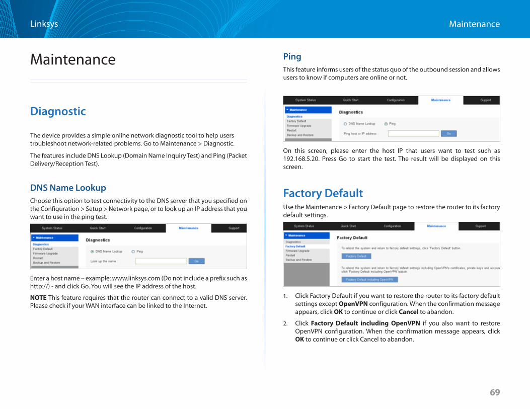
69
Maintenance Linksys
69
Maintenance
Diagnostic
The device provides a simple online network diagnostic tool to help users troubleshoot network-related problems . Go to Maintenance > Diagnostic .
The features include DNS Lookup (Domain Name Inquiry Test) and Ping (Packet Delivery/Reception Test) .
DNS Name LookupChoose this option to test connectivity to the DNS server that you specified on the Configuration > Setup > Network page, or to look up an IP address that you want to use in the ping test .
Enter a host name – example: www .linksys .com (Do not include a prefix such as http://) - and click Go . You will see the IP address of the host .
NOTE This feature requires that the router can connect to a valid DNS server . Please check if your WAN interface can be linked to the Internet .
PingThis feature informs users of the status quo of the outbound session and allows users to know if computers are online or not .
On this screen, please enter the host IP that users want to test such as 192 .168 .5 .20 . Press Go to start the test . The result will be displayed on this screen .
Factory DefaultUse the Maintenance > Factory Default page to restore the router to its factory default settings .
1 . Click Factory Default if you want to restore the router to its factory default settings except OpenVPN configuration . When the confirmation message appears, click OK to continue or click Cancel to abandon .
2 . Click Factory Default including OpenVPN if you also want to restore OpenVPN configuration . When the confirmation message appears, click OK to continue or click Cancel to abandon .
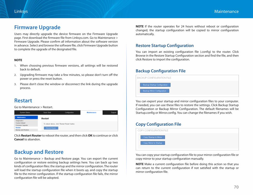
70
Maintenance Linksys
Firmware UpgradeUsers may directly upgrade the device firmware on the Firmware Upgrade page . First download the firmware file from Linksys .com . Go to Maintenance > Firmware Upgrade . Please confirm all information about the software version in advance . Select and browse the software file, click Firmware Upgrade button to complete the upgrade of the designated file .
NOTE
1 . When choosing previous firmware versions, all settings will be restored back to default .
2 . Upgrading firmware may take a few minutes, so please don’t turn off the power or press the reset button .
3 . Please don’t close the window or disconnect the link during the upgrade process .
RestartGo to Maintenance > Restart .
Click Restart Router to reboot the router, and then click OK to continue or click Cancel to abandon .
Backup and RestoreGo to Maintenance > Backup and Restore page . You can export the current configuration or restore existing backup settings here . You can back up two kinds of configuration files: the startup and the mirror configuration . The router will load the startup configuration file when it boots up, and copy the startup file to the mirror configuration . If the startup configuration file fails, the mirror configuration file will be adopted .
NOTE If the router operates for 24 hours without reboot or configuration changed, the startup configuration will be copied to mirror configuration automatically .
Restore Startup ConfigurationYou can import an existing configuration file ( .config) to the router . Click Browse in the Restore Startup Configuration section and find the file, and then click Restore to import the configuration .
Backup Configuration File
You can export your startup and mirror configuration files to your computer . If needed, you can use these files to restore the settings . Click Backup Startup Configuration or Backup Mirror Configuration . The default filenames will be Startup .config or Mirror .config . You can change the filenames if you wish .
Copy Configuration File
You can copy your startup configuration file to your mirror configuration file or copy mirror to your startup configuration manually .
NOTE Make a current configuration file before doing this action so that you can return to the current configuration if not satisfied with the startup or mirror configuration file .
71
Technical SupportLinksys
Technical Support
Click Support tab to search for more information about the router or technical support from Linksys support team .
Product Website
Click Launch Now to visit product website to get more information about the router .
Linksys Support Website
Click Launch Now to visit Linksys support website to get more support for the router .
72
FAQ and Supplemental InformationLinksys
FAQ and Supplemental Information
Click on the following links for more information about operation of your router .
LRT214/LRT224 • Product comparison between LRT214 and LRT224
• LRT214 and LRT224 Frequently Asked Questions
• Recovering the LRT214 and LRT224 from a failed firmware upgrade using TFTP
• How to create a VLAN on the Linksys Gigabit VPN Routers, LRT214 and LRT224
• Setting up PPTP on LRT214/LRT224 and Windows computer
• EasyLink VPN Frequently Asked Questions
• Locating the IP address of your Smart Switch using a Linksys Small Business router
• Configuring the Linksys Gigabit VPN Router with OpenVPN
• Establishing Client to Gateway IPsec Tunnel with Shrewsoft VPN Client
• Configuring OpenVPN on your Android™ device
• How to create an Access Rule on the Linksys Gigabit VPN Router
• How to configure One-to-One NAT on the Linksys Gigabit VPN Router
• Establishing Client to Gateway IPsec Tunnel with IPSecuritas VPN Client
• Accessing the web-based setup page of the Linksys Gigabit VPN router
• Configuring OpenVPN for iOS device
• Setting up web, email, DNS or FTP servers on the Linksys Gigabit VPN Router
• Blocking a Domain or website by using keywords on the Linksys Gigabit VPN Router
• Creating an IPSec tunnel Client to Gateway on a Linksys Gigabit VPN router
• Creating an IPSec tunnel Gateway to Gateway on a Linksys VPN router
• Setting up the Linksys Gigabit VPN Router using the Basic Setup Wizard
• Configuring a VPN connection on your iPad®
• Disabling VPN in your iPad®
• Connecting to a VPN Tunnel Using a Router
• Creating VLAN Trunking Using the Linksys Manageable Switches
• Checking the VPN Settings on a Linksys Router
• Setting-Up a VPN Tunnel on Two Linksys Routers
• Setting up and connecting to a VPN on your iPhone®
• How to Setup Multi-Site VPN
• Encountering difficulties when connecting to the VPN Tunnel using a Linksys router
LRT214 • Getting to know the Linksys LRT214
LRT224 • Getting to know the Linksys LRT224

Visit linksys.com/support for award-winning technical support
© 2015 Belkin International, Inc. and/or its affiliates. All rights reserved. BELKIN, LINKSYS and many product names and logos are trademarks of the Belkin group of companies. Third-party trademarks mentioned are the property of their respective owners.
8820-01696 Rev. C02