frick quantum™ acuair control panel
TRANSCRIPT

MAINTENANCE
FRICK® QUANTUM™ACUair®
CONTROL PANELVERSION 2.1x
S90-500 M/JULY 2002File: SERVICE MANUAL - SECTION 90Replaces: NOTHING (New Information)Dist: 3, 3a, 3b, 3c

S90-500 M FRICK QUANTUM™ ACUair CONTROL PANELPage 2 MAINTENANCE
Table of Contents
QUANTUM™ CONTROLLER BOARD IDENTIFICATION ...................................................................................5Introduction....................................................................................................................................................5
Quantum™ 3.............................................................................................................................................5Quantum™ 4.............................................................................................................................................5
Troubleshooting .............................................................................................................................................5The Quantum™ Control Panel .......................................................................................................................5General Information: ......................................................................................................................................5Acuair® System Description............................................................................................................................6What To Do Before Calling The Factory .........................................................................................................6Replacing The Quantum™ Board...................................................................................................................6
QUANTUM™ 3 CONTROLLER...........................................................................................................................7What Should Occur When Powering Up The Panel ........................................................................................7What If The “Air Handling Unit Overview” Screen Is Not Shown......................................................................7Controller Board Pictorial ...............................................................................................................................8Board Settings ...............................................................................................................................................8
Processor Board Jumpers........................................................................................................................8Communications Board Jumpers .............................................................................................................8
Flow Diagram - D.C. Voltage / Communications Wiring ..................................................................................9
QUANTUM™ 4 CONTROLLER.........................................................................................................................10What Should Occur When Powering Up The Panel ......................................................................................10What If The “Air Handling Unit Overview” .....................................................................................................10Screen Is Not Shown ...................................................................................................................................10Controller Board Pictorial .............................................................................................................................11Board Settings .............................................................................................................................................11Processor Board Jumpers............................................................................................................................11Communications Board Jumpers..................................................................................................................11
Com-1 (TB1)..........................................................................................................................................11Com-2 (TB2 - TB3) ................................................................................................................................11
Flow Diagram - D.C. Voltage / Communications Wiring ................................................................................12
GCU (GENERAL CONTROL UNIT) ...................................................................................................................13GCU Board Description................................................................................................................................13Communications Led's .................................................................................................................................13Connections To The Quantum™..................................................................................................................13Logic Voltage (Power) Leds .........................................................................................................................13Status Led ...................................................................................................................................................13Digital Inputs................................................................................................................................................13Digital Outputs .............................................................................................................................................14Checking The Digital Inputs And Outputs .....................................................................................................14Fuse Testing And Replacement ...................................................................................................................14Input And Output Module Testing And Replacement ....................................................................................15Troubleshooting An Output ..........................................................................................................................15Troubleshooting An Input .............................................................................................................................15Replacing A Defective Gcu Board ................................................................................................................15ACUair® GCU Control Panel Flow Diagram - D.C. Voltage / Communications Wiring....................................16
PICTORIAL DRAWING OF ACUAIR® (GCU) BOARD:......................................................................................17GCU Board Settings.....................................................................................................................................17Communications Port Connections...............................................................................................................17Additional Communications Jumper Configurations ......................................................................................17GCU Board Dipswitch Settings.....................................................................................................................17
GCU BOARD ANALOG I/O JUMPER SETTINGS .............................................................................................17GCU Board Analog I/O Jumper Settings (Continued)....................................................................................19Analog Output Configurations.......................................................................................................................19“Service Screen” - GCU Board Digital and Analog Inputs and Outputs..........................................................19
FRICK QUANTUM™ ACUair CONTROL PANEL S90-500 M MAINTENANCE Page 3
ANALOG BOARD............................................................................................................................................. 20Analog Board Description ............................................................................................................................ 20Connections to the Quantum™.................................................................................................................... 20Analog Inputs .............................................................................................................................................. 20Analog Outputs............................................................................................................................................ 20Checking the Analog Inputs and Outputs ..................................................................................................... 20Replacing a Defective Analog Board............................................................................................................ 21Analog Board Settings................................................................................................................................. 21
Communications Settings...................................................................................................................... 21Dipswitch Settings................................................................................................................................. 21
Additional Service Related Screens ............................................................................................................. 22GCU “About” Screen ............................................................................................................................. 22Quantum™ “About” Screen ................................................................................................................... 22 “Change Communications” Screen ....................................................................................................... 23
QUANTUM™ POWER SUPPLY ADJUSTMENT AND REPLACEMENT ........................................................... 24Adjustment .................................................................................................................................................. 24Replacement ............................................................................................................................................... 24Quantum™ +5 DC Voltage Measurement Location...................................................................................... 25
IDENTIFYING THE TYPE OF DISPLAY ............................................................................................................ 27Display Replacement................................................................................................................................... 27Display Assembly Component Replacement Guide...................................................................................... 27Troubleshooting A Problem That Appears Unexplainable............................................................................. 28
SETPOINT DATA SHEETS............................................................................................................................... 29Control Setup .............................................................................................................................................. 29
Cooling Control Setup ........................................................................................................................... 30Cooling ........................................................................................................................................... 30Stage #1 ......................................................................................................................................... 30Stage #2 ......................................................................................................................................... 30Stage #3 ......................................................................................................................................... 30Stage #4 ......................................................................................................................................... 30Cleanup .......................................................................................................................................... 30
Heating Control Setup ........................................................................................................................... 31Heating ........................................................................................................................................... 31Cleanup .......................................................................................................................................... 31
Pre-Heat Control Setup ......................................................................................................................... 32Pre-Heat ......................................................................................................................................... 32Cleanup .......................................................................................................................................... 32
Exhaust Control Setup .......................................................................................................................... 33Stage #1 ......................................................................................................................................... 33Stage #2 ......................................................................................................................................... 33
Damper Control Setup........................................................................................................................... 34Room Pressure High Limit .............................................................................................................. 34Room Pressure Control................................................................................................................... 34Economizer..................................................................................................................................... 34
Heat Profile Control Setup..................................................................................................................... 35Humidity Control Setup.......................................................................................................................... 36
Dehumidification ............................................................................................................................. 36Humidification ................................................................................................................................. 36
Safety Setpoints Setup.......................................................................................................................... 37Ammonia ........................................................................................................................................ 37Discharge Air .................................................................................................................................. 37Auxiliary .......................................................................................................................................... 37
Defrost Setpoints Setup......................................................................................................................... 38Defrost Timers ................................................................................................................................ 38Defrost Digital Input ........................................................................................................................ 38Defrost Schedule ............................................................................................................................ 38
S90-500 M FRICK QUANTUM™ ACUair CONTROL PANELPage 4 MAINTENANCE
Auxilliary Analog Inputs (12 & 13) Setup ................................................................................................39Aux. Input #12 .................................................................................................................................39Aux. Input #13 .................................................................................................................................39
Auxilliary Analog Inputs (14 & 15) Setup ................................................................................................40Aux. Input #14 .................................................................................................................................40Aux. Input #13 .................................................................................................................................40
Auxilliary Analog Outputs (5, 6, & 7) Setup.............................................................................................41Aux. Output #5 ................................................................................................................................41Aux. Output #6 ................................................................................................................................41Aux. Output #7 ................................................................................................................................41
Auxilliary Analog Output #5 Setup..........................................................................................................42Auxilliary Analog Output #6 Setup..........................................................................................................43Auxilliary Analog Output #7 Setup..........................................................................................................44Panel Setup...........................................................................................................................................45
Temperature Units...........................................................................................................................46Communications..............................................................................................................................46
Selectable Options.................................................................................................................................47Calibration .............................................................................................................................................48
Pressure..........................................................................................................................................48Pressure Transducer .......................................................................................................................48Temperature....................................................................................................................................48Temperature Sensor........................................................................................................................48Other Calibration .............................................................................................................................49Sensor.............................................................................................................................................49Other Calibration .............................................................................................................................49Analog Input ....................................................................................................................................49Analog Output Calibration................................................................................................................50Analog Output .................................................................................................................................50
QUANTUM™ DRAWINGS.................................................................................................................................51Quantum™ D.C. Power Supply Harness ......................................................................................................51Quantum™ I/O & D.C. Power Harness.........................................................................................................51ACUair® Standard Control Panel Wiring Diagram .........................................................................................52
Digital Wiring Notes ...............................................................................................................................54Analog Wiring Notes ..............................................................................................................................59
Acuair® Standard GCU Control Panel Layout Diagram .................................................................................61Acuair® Standard Component And Symbol Identification ..............................................................................62Quantum™ To GCU Communications..........................................................................................................63Quantum™ RS-422 Communications To Customer Remote Computer/DCS ................................................63Quantum™ RS-485 Communications To Customer Remote Computer/DCS ................................................63Quantum™ 3 RS-232 Communications To Customer Remote Computer/DCS .............................................63Quantum™ 4 RS-232 Communications To Customer Remote Computer/DCS .............................................63
RECOMMENDED SPARE PARTS.....................................................................................................................64
INDEX................................................................................................................................................................65
THE FOLLOWING PUBLICATIONS ARE AVAILABLEFROM THE FRICK® WEBSITE
frickcold.com
S90-500 O Frick® Quantum™ Control PanelOPERATION
S90-500 CS Frick® Quantum™ Control PanelCOMMUNICATIONS SETUP (setup andwiring for data communication using availableprotocols)
S90-500 M Frick® Quantum™ Control PanelMAINTENANCE (repair and troubleshooting)
Indicates an imminentlyhazardous situation which, if notavoided, will result in death orserious injury.
Indicates a potentially hazardoussituation or practice which, if notavoided, will result in death orserious injury.
Indicates a potentially hazardoussituation or practice which, if notavoided, will result in damage toequipment and/or minor injury.
NOTE: Indicates an operating procedure, practice, etc., orportion thereof which is essential to highlight.
CAUTION!
WARNING!
DANGER!
FRICK QUANTUM™ ACUair CONTROL PANEL S90-500 M MAINTENANCE Page 5
QUANTUM™ CONTROLLER BOARD IDENTIFICATION
INTRODUCTION
Frick® Controls has over the years, strived to remain onthe cutting edge of microprocessor technology anddevelopment. In addition, because of the ever-increasingspeed, memory, features, and power of microprocessors,Frick® Controls will continue to introduce the latestadvancement in microprocessor control technology.
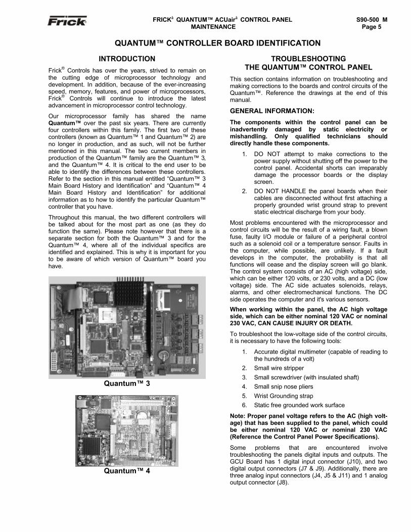
Our microprocessor family has shared the nameQuantum™ over the past six years. There are currentlyfour controllers within this family. The first two of thesecontrollers (known as Quantum™ 1 and Quantum™ 2) areno longer in production, and as such, will not be furthermentioned in this manual. The two current members inproduction of the Quantum™ family are the Quantum™ 3,and the Quantum™ 4. It is critical to the end user to beable to identify the differences between these controllers.Refer to the section in this manual entitled “Quantum™ 3Main Board History and Identification” and “Quantum™ 4Main Board History and Identification” for additionalinformation as to how to identify the particular Quantum™controller that you have.
Throughout this manual, the two different controllers willbe talked about for the most part as one (as they dofunction the same). Please note however that there is aseparate section for both the Quantum™ 3 and for theQuantum™ 4, where all of the individual specifics areidentified and explained. This is why it is important for youto be aware of which version of Quantum™ board youhave.
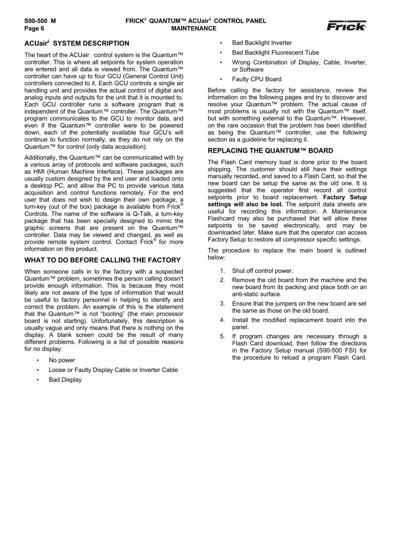
Quantum™ 3
Quantum™ 4
TROUBLESHOOTINGTHE QUANTUM™ CONTROL PANEL
This section contains information on troubleshooting andmaking corrections to the boards and control circuits of theQuantum™. Reference the drawings at the end of thismanual.
GENERAL INFORMATION:
The components within the control panel can beinadvertently damaged by static electricity ormishandling. Only qualified technicians shoulddirectly handle these components.
1. DO NOT attempt to make corrections to thepower supply without shutting off the power to thecontrol panel. Accidental shorts can irreparablydamage the processor boards or the displayscreen.
2. DO NOT HANDLE the panel boards when theircables are disconnected without first attaching aproperly grounded wrist ground strap to preventstatic electrical discharge from your body.
Most problems encountered with the microprocessor andcontrol circuits will be the result of a wiring fault, a blownfuse, faulty I/O module or failure of a peripheral controlsuch as a solenoid coil or a temperature sensor. Faults inthe computer, while possible, are unlikely. If a faultdevelops in the computer, the probability is that allfunctions will cease and the display screen will go blank.The control system consists of an AC (high voltage) side,which can be either 120 volts, or 230 volts, and a DC (lowvoltage) side. The AC side actuates solenoids, relays,alarms, and other electromechanical functions. The DCside operates the computer and it's various sensors.
When working within the panel, the AC high voltageside, which can be either nominal 120 VAC or nominal230 VAC, CAN CAUSE INJURY OR DEATH.
To troubleshoot the low-voltage side of the control circuits,it is necessary to have the following tools:
1. Accurate digital multimeter (capable of reading tothe hundreds of a volt)
2. Small wire stripper
3. Small screwdriver (with insulated shaft)4. Small snip nose pliers
5. Wrist Grounding strap6. Static free grounded work surface
Note: Proper panel voltage refers to the AC (high volt-age) that has been supplied to the panel, which couldbe either nominal 120 VAC or nominal 230 VAC(Reference the Control Panel Power Specifications).
Some problems that are encountered involvetroubleshooting the panels digital inputs and outputs. TheGCU Board has 1 digital input connector (J10), and twodigital output connectors (J7 & J9). Additionally, there arethree analog input connectors (J4, J5 & J11) and 1 analogoutput connector (J8).
S90-500 M FRICK QUANTUM™ ACUair CONTROL PANELPage 6 MAINTENANCE
ACUair SYSTEM DESCRIPTION
The heart of the ACUair control system is the Quantum™controller. This is where all setpoints for system operationare entered and all data is viewed from. The Quantum™controller can have up to four GCU (General Control Unit)controllers connected to it. Each GCU controls a single airhandling unit and provides the actual control of digital andanalog inputs and outputs for the unit that it is mounted to.Each GCU controller runs a software program that isindependent of the Quantum™ controller. The Quantum™program communicates to the GCU to monitor data, andeven if the Quantum™ controller were to be powereddown, each of the potentially available four GCU’s willcontinue to function normally, as they do not rely on theQuantum™ for control (only data acquisition).
Additionally, the Quantum™ can be communicated with bya various array of protocols and software packages, suchas HMI (Human Machine Interface). These packages areusually custom designed by the end user and loaded ontoa desktop PC, and allow the PC to provide various dataacquisition and control functions remotely. For the enduser that does not wish to design their own package, aturn-key (out of the box) package is available from Frick®
Controls. The name of the software is Q-Talk, a turn-keypackage that has been specially designed to mimic thegraphic screens that are present on the Quantum™controller. Data may be viewed and changed, as well asprovide remote system control. Contact Frick® for moreinformation on this product.
WHAT TO DO BEFORE CALLING THE FACTORY
When someone calls in to the factory with a suspectedQuantum™ problem, sometimes the person calling doesn'tprovide enough information. This is because they mostlikely are not aware of the type of information that wouldbe useful to factory personnel in helping to identify andcorrect the problem. An example of this is the statementthat the Quantum™ is not “booting” (the main processorboard is not starting). Unfortunately, this description isusually vague and only means that there is nothing on thedisplay. A blank screen could be the result of manydifferent problems. Following is a list of possible reasonsfor no display:
• No power
• Loose or Faulty Display Cable or Inverter Cable
• Bad Display
• Bad Backlight Inverter
• Bad Backlight Fluorescent Tube
• Wrong Combination of Display, Cable, Inverter,or Software
• Faulty CPU Board
Before calling the factory for assistance, review theinformation on the following pages and try to discover andresolve your Quantum™ problem. The actual cause ofmost problems is usually not with the Quantum™ itself,but with something external to the Quantum™. However,on the rare occasion that the problem has been identifiedas being the Quantum™ controller, use the followingsection as a guideline for replacing it.
REPLACING THE QUANTUM™ BOARD
The Flash Card memory load is done prior to the boardshipping. The customer should still have their settingsmanually recorded, and saved to a Flash Card, so that thenew board can be setup the same as the old one. It issuggested that the operator first record all controlsetpoints prior to board replacement. Factory Setupsettings will also be lost. The setpoint data sheets areuseful for recording this information. A MaintenanceFlashcard may also be purchased that will allow thesesetpoints to be saved electronically, and may bedownloaded later. Make sure that the operator can accessFactory Setup to restore all compressor specific settings.
The procedure to replace the main board is outlinedbelow:
1. Shut off control power.2. Remove the old board from the machine and the
new board from its packing and place both on ananti-static surface.
3. Ensure that the jumpers on the new board are setthe same as those on the old board.
4. Install the modified replacement board into thepanel.
5. If program changes are necessary through aFlash Card download, then follow the directionsin the Factory Setup manual (S90-500 FSI) forthe procedure to reload a program Flash Card.

FRICK QUANTUM™ ACUair CONTROL PANEL S90-500 M MAINTENANCE Page 7
QUANTUM™ 3 CONTROLLER
WHAT SHOULD OCCUR WHEN POWERING UPTHE PANEL
The first thing that should be checked whentroubleshooting the Quantum™ is it’s powering upsequence.
When powering up the Quantum™, the followingsequence of events is indicative of a properly workingmain processor board:
• The LED’s for +5V, +12V, and –12V will turn onsolid. (Lower left corner of Main PCB)
• LED KB will begin to blink. (Left side of MainPCB)
• Several initialization screens will appear (thesewill look very similar to the way the screen of adesktop computer appears when it is booting.
• The last of the initialization screens is the“System Configuration” screen.
• Various POST codes will appear.
• The screen will go then show Looking forboards…
• The “Air Handling Unit Overview” screen isshown.
After the Quantum™ has properly powered up, thefollowing sequence of events is indicative of propercommunication to the connected GCU boards:
• The TX/RX LED’s near the white connector willbegin to blink.
• All connected GCU boards' TX/RX lights shouldbe blinking.
• Each GCU board should have the power LED’s(+5 and +12) lighted and the “Status” LED shouldbe blinking.
WHAT IF THE “AIR HANDLING UNIT OVERVIEW”SCREEN IS NOT SHOWN
If the “Air Handling Unit Overview” screen is not shown,check the following items:
1. If no LED’s are lighted, then check AC and DCpower.
2. Check if the lighting of the LED’s is occurring asdescribed in the “What Should Occur WhenPowering Up The Panel” section.
• If the powering up sequence continues torepeat without displaying the “Air HandlingUnit Overview” screen, then there is a“booting” problem.
3. Check if an error message is displayed whenbooting.
• Be sure to write down any error messagesexactly as they appear.
4. Check that the software is OK:• Is the correct software installed?• Did you just install new software?
• Is the program that the Quantum™ isrunning the same that all GCU boards arerunning?
• If you need to clear the numerical setpointand calibration areas of memory for anyreason, clear the memory as described inthe S90-500 FSI publication. NOTE: Thisinformation will be replaced by factorydefault values, so any setpoint andcalibration data values that need to becustomized must be reentered.
5. Check for bad or loose connections.
6. Check the display. If the CPU board is bootingbut you have no display, check the following:
• Check the LCD backlight tube. Look veryclosely at the display to see if anything isvisible in the dark screen. Using a beam typesource of good lighting, such as a flashlight,look for any “ghost” type image. If it appearsthat there is something on the screen butvery dark, the problem maybe the LCDbacklight tube. On the LG Philips, NEC, andSharp displays this tube is field replaceable.On the Samsung LCD display, it is notavailable and the display will have to bereplaced. There may be a sticker on thedisplay mounting plate. If there is, it will havea part number that describes the type ofdisplay. If there is no sticker, you must takethe display apart to identify the displaymanufacturer.
• Verify that both the display cable and theinverter cable are firmly seated. It may benecessary to remove the video cable fromthe back of the LCD display and reseat it tobe sure it is connected properly. Note: Thisis a small connector and caution shouldbe observed so that it is not damageddue to excessive force.
• Check the backlight inverter connector (P4).When the Quantum™ board is mounted inthe panel, this connector is located at themiddle left of the board. The pins on the rightside are odd numbered, with pin P(1) at thebottom -pin P(9) at the top. The pins on theleft side are even numbered, with pin P(2) atthe bottom - pin P(10) at the top. After theQuantum™ has booted, pin P(3) shouldmeasure +2.4 Vdc, pins P(4) and P(5) areDC grounds, and pins P(6) and P(7) shouldmeasure +12 Vdc. A bad inverter will alsocause a dark display.
• Reference the “Display AssemblyComponent Replacement Guide” in the“Identifying the Type of Display” section thatappears later in this manual, and check thatthe LCD, LCD cable, and software versionsare matched correctly.
S90-500 M FRICK QUANTUM™ ACUair CONTROL PANELPage 8 MAINTENANCE
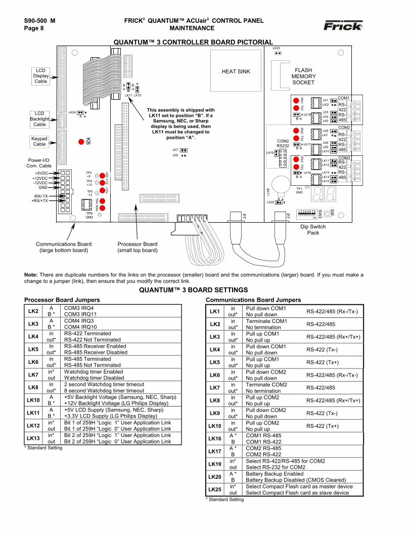
QUANTUM™ 3 CONTROLLER BOARD PICTORIAL
Note: There are duplicate numbers for the links on the processor (smaller) board and the communications (larger) board. If you must make achange to a jumper (link), then ensure that you modify the correct link.
QUANTUM™ 3 BOARD SETTINGSProcessor Board Jumpers
LK2 AB *
COM3 IRQ4COM3 IRQ11
LK3 AB *
COM4 IRQ3COM4 IRQ10
LK4 inout*
RS-422 TerminatedRS-422 Not Terminated
LK5 Inout*
RS-485 Receiver EnabledRS-485 Receiver Disabled
LK6 inout*
RS-485 TerminatedRS-485 Not Terminated
LK7 in*out
Watchdog timer EnabledWatchdog timer Disabled
LK8 inout*
2 second Watchdog timer timeout8 second Watchdog timer timeout
LK10 AB *
+5V Backlight Voltage (Samsung, NEC, Sharp)+12V Backlight Voltage (LG Philips Display)
LK11 AB *
+5V LCD Supply (Samsung, NEC, Sharp)+3.3V LCD Supply (LG Philips Display)
LK12 in*out
Bit 1 of 259H “Logic 1” User Application LinkBit 1 of 259H “Logic 0” User Application Link
LK13 in*out
Bit 2 of 259H “Logic 1” User Application LinkBit 2 of 259H “Logic 0” User Application Link
* Standard Setting
Communications Board Jumpers
LK1 inout*
Pull down COM1No pull down RS-422/485 (Rx-/Tx-)
LK2 inout*
Terminate COM1No termination RS-422/485
LK3 inout*
Pull up COM1No pull up
RS-422/485 (Rx+/Tx+)
LK4 inout*
Pull down COM1No pull down RS-422 (Tx-)
LK5 inout*
Pull up COM1No pull up RS-422 (Tx+)
LK6 inout*
Pull down COM2No pull down RS-422/485 (Rx-/Tx-)
LK7 inout*
Terminate COM2No termination
RS-422/485
LK8 inout*
Pull up COM2No pull up RS-422/485 (Rx+/Tx+)
LK9 inout*
Pull down COM2No pull down RS-422 (Tx-)
LK10 inout*
Pull up COM2No pull up RS-422 (Tx+)
LK16 A *B
COM1 RS-485COM1 RS-422
LK17 A *B
COM2 RS-485COM2 RS-422
LK19 in*out
Select RS-422/RS-485 for COM2Select RS-232 for COM2
LK20 A *B
Battery Backup EnabledBattery Backup Disabled (CMOS Cleared)
LK25 in*out
Select Compact Flash card as master deviceSelect Compact Flash card as slave device
* Standard Setting
COM2
-12V+5VTP3
+5
TP4+12
TP5-12
RX
4TX
4
TP6GND
+12
Power-I/OCom. Cable
+12VDC-12VDC
GND
-RX/-TX+RX/+TX
LK11
BA
LK10
BA
KB
This assembly is shipped withLK11 set to position “B”. If a
Samsung, NEC, or Sharpdisplay is being used, thenLK11 must be changed to
position “A”.KeypadCable
LK7
LK8
LCDDisplayCable
LCDBacklight
Cable
LK24B A
HEAT SINK
COM2RS232
LK19
FLASHMEMORYSOCKET
SW
Dip SwitchPack
BA
T1
SW
2
ON
1 2 3 4 5 6 7 8
LK20B A
P7
P7
TP1GND
COM31
2
3
4
RS-422RS-485
LK12LK11
LK13LK14LK15
TX3
RX
3
LK18B A
B A
1
2
3
4
RS-422RS-485
LK6
LK8LK9LK10
LK7TX2
RX
2
LK17
COM1LK1LK2
LK3LK4LK5
1
2
3
4
RS-422RS-485
LK16B A
TX1
RX
1
LK25
+5VDC
Communications Board(large bottom board)
Processor Board(small top board)
FRICK QUANTUM™ ACUair CONTROL PANEL S90-500 M MAINTENANCE Page 9
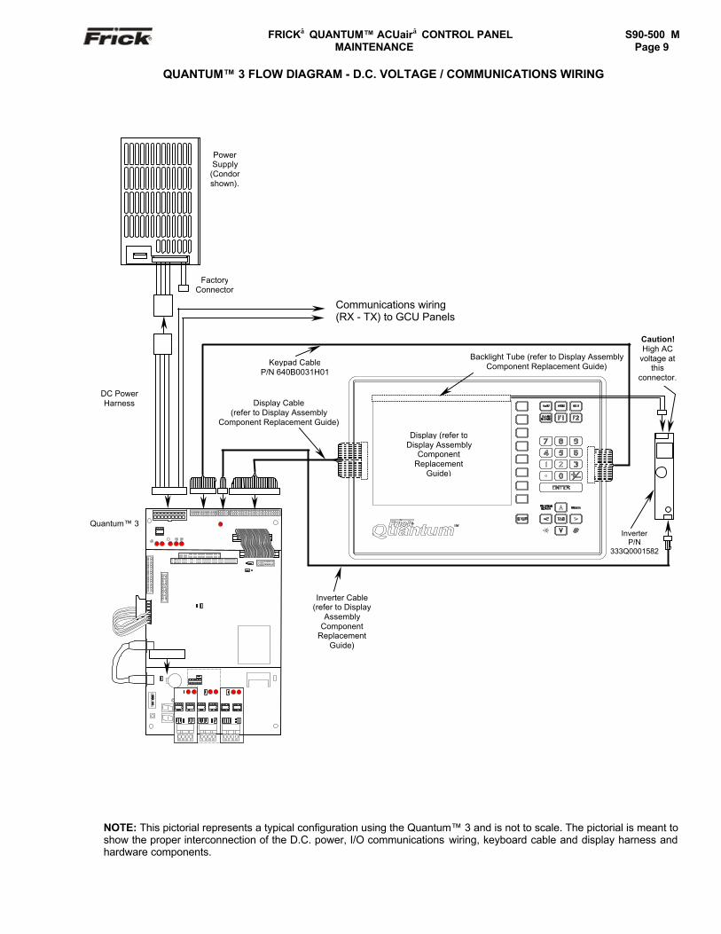
QUANTUM™ 3 FLOW DIAGRAM - D.C. VOLTAGE / COMMUNICATIONS WIRING
NOTE: This pictorial represents a typical configuration using the Quantum™ 3 and is not to scale. The pictorial is meant toshow the proper interconnection of the D.C. power, I/O communications wiring, keyboard cable and display harness andhardware components.
Caution!High AC
voltage atthis
connector.
Display Cable(refer to Display Assembly
Component Replacement Guide)
Quantum™ 3
DC PowerHarness
PowerSupply(Condorshown).
FactoryConnector
InverterP/N
333Q0001582
Inverter Cable(refer to Display
AssemblyComponent
ReplacementGuide)
Backlight Tube (refer to Display AssemblyComponent Replacement Guide)Keypad Cable
P/N 640B0031H01
Communications wiring(RX - TX) to GCU Panels
Display (refer toDisplay Assembly
ComponentReplacement
Guide)

S90-500 M FRICK QUANTUM™ ACUair CONTROL PANELPage 10 MAINTENANCE
QUANTUM™ 4 CONTROLLER
WHAT SHOULD OCCUR WHEN POWERING UPTHE PANEL
The first thing that should be checked whentroubleshooting the Quantum™ is it’s powering upsequence.
When powering up the Quantum™, the followingsequence of events is indicative of a properly workingmain processor board:
• Green PWR (Power) LED will turn on solid (upperright corner of main PCB).
• Red FLASH LED will begin to intermittentlyduring the Boot process. It will then go out oncethe “Air Handling Unit Overview” screen appears.
• LED D8 (on the smaller board) will start to blinkat the rate of about once per second. It willcontinue to blink after the Quantum™ hasbooted.
• Several initialization screens will appear (thesewill look very similar to the way the screen of adesktop computer appears when it is booting.
• The last of the initialization screens is the“System Configuration” screen.
• Various POST codes will appear.
• The screen will go then show “Reading DataFrom File"
• “Looking For Boards”, will be seen next
• After the screen displays "Looking For Boards",LED's D4, D5, D7 and D8 will be on solid.
• The “Air Handling Unit Overview” screen willappear.
• Once actual data has been displayed on thisscreen, LED D13 will come on solid and D10,D11, and D12 will start to flash at a quick rate.
After the Quantum™ has properly powered up, thefollowing sequence of events is indicative of propercommunication to the analog and digital boards:
• The TX/RX LED’s near the white connector willbegin to blink.
• All connected GCU boards' TX/RX lights shouldbe blinking.
• Each GCU board should have the power LED’s(+5 and +12) lighted and the “Status” LED shouldbe blinking.
WHAT IF THE “Air Handling Unit Overview”SCREEN IS NOT SHOWN
If the “Air Handling Unit Overview” screen is not shown,check the following items:
1. If no LED’s are lighted, then check power AC andDC.
2. Check if the lighting of the LED’s is occurring asdescribed in the “What Should Occur WhenPowering Up The Panel” section.
• If the powering up sequence continues torepeat without displaying the “Air HandlingUnit Overview” screen, then there is abooting problem.
3. Check if an error message is displayed whenbooting.
• Be sure to write down any error messagesexactly as they appear.
4. Check that the software is OK:
• Is the correct software installed?
• Did you just install new software?
• If you need to clear the numerical setpointand calibration areas of memory for anyreason, clear the memory as described inthe S90-500 FSI publication. NOTE: Thisinformation will be replaced by factorydefault values, so any setpoint andcalibration data values that need to becustomized must be reentered.
5. Check for bad connections.
6. Check the display. If the CPU board is bootingbut you have no display, check the following:
• Check the LCD backlight tube. Look veryclosely at the display to see if anything isvisible in the dark screen. Using a beam typesource of good lighting, such as a flashlight,look for any “ghost” type image. If it appearsthat there is something on the screen butvery dark, the problem maybe the LCDbacklight tube. On the LG Philips, NEC, andSharp displays this tube is field replaceable.On the Samsung LCD display, it is notavailable and the display will have to bereplaced. There may be a sticker on thedisplay mounting plate. If there is, it will havea part number that describes the type ofdisplay. If there is no sticker, you must takethe display apart to identify the displaymanufacturer.
• Verify that both the display cable and theinverter cable are firmly seated. Thesecables both originate from the sameconnector on the Quantum™. It may benecessary to remove the video cable fromthe back of the LCD display and reseat it tobe sure it is connected properly. Note: Thisis a small connector and caution shouldbe observed so that it is not damageddue to excessive force.
• Reference the “Display AssemblyComponent Replacement Guide” at the endof this section, and check that the LCD, LCDcable, and software versions are matchedcorrectly.

FRICK QUANTUM™ ACUair CONTROL PANEL S90-500 M MAINTENANCE Page 11
QUANTUM™ 4 CONTROLLER BOARD PICTORIAL
Note: There are duplicate numbers for the links on the processor (larger) board and the communications (smaller) board. If you must make achange to a jumper (link), then ensure that you modify the correct link.
QUANTUM™ 4 BOARD SETTINGS
Processor Board Jumpers (Bottom Board)
LK1 inout*
2 second Watchdog timer timeout8 second Watchdog timer timeout
LK2 in*out
Watchdog timer EnabledWatchdog timer Disabled
LK3 AB *
+5V Backlight Voltage (Samsung, NEC, Sharp)+12V Backlight Voltage (LG Philips Display)
LK4 AB *
+5V LCD Supply (Samsung, NEC, Sharp)+3.3V LCD Supply (LG Philips Display)
LK5 AB *
COM4 IRQ3COM4 IRQ10
LK6 AB *
COM3 IRQ4COM3 IRQ11
LK7 A *B
Battery Backup EnabledBattery Backup Disabled (CMOS Cleared)
LK8 in*out
RS-485 Receiver EnabledRS-485 Receiver Disabled
LK9 in*out
RS-485 TerminatedRS-485 Not Terminated
LK10 inout*
RS-422 TerminatedRS-422 Not Terminated
LK11 in*out
Bit 1 of 259H “Logic 1” User Application LinkBit 1 of 259H “Logic 0” User Application Link
LK12 in*out
Bit 2 of 259H “Logic 1” User Application LinkBit 2 of 259H “Logic 0” User Application Link
* Standard Setting
Communications Board Jumpers (Top Board)Com-1 (TB1)
LK2 inout*
Terminate COM1No termination RS-422/485
LK7 inout*
Pull down COM1No pull down RS-422/485 (Rx-/Tx-)
LK8 inout*
Pull up COM1No pull up
RS-422/485 (Rx-/Tx+)
LK9 inout*
Pull down COM1No pull down
RS-422 (Tx-)
LK10 inout*
Pull up COM1No pull up RS-422 (Tx+)
LK16 AB*
COM1 RS-422 (TB1)COM1 RS-485 (TB1)
* Standard Setting
Com-2 (TB2 - TB3)
LK1 inout*
Terminate COM2No termination RS-422/485
LK3 inout*
Pull down COM2No pull down RS-422/485 (Rx-/Tx-)
LK4 inout*
Pull up COM2No pull up RS-422/485 (Rx-/Tx+)
LK5 inout*
Pull down COM2No pull down
RS-422 (Tx-)
LK6 inout*
Pull up COM2No pull up RS-422 (Tx+)
LK11 AB*
Select RS-232 for COM2 (TB2)Select RS-422/RS-485 for COM2 (TB3)
LK17 AB*
COM2 RS-422 (TB2)COM2 RS-485 (TB2)
* Standard Setting
PWR
SUSP
FLASH
LK11 LK12
PL24
PL3
PL
LK9
LK8LK10
PL16
LK1
PL7
PL9
LK2
PL17
PL12
PL19
PL18
PL14
PL10
PL6
PL2
PL4
PL1
Flash CardSocket
(Locatedunderboard)
PL3PL5
PL11
LK3
AB
LK4
PL15
+5VDC
+12VDC
RET / GNDRET / GND
+RX/+TX-RX/-TX
PowerCable
PL8
I/O Cable
TB1TB2
LK2COM-2 TB3
RS
-232
3
21
PL13
This assembly isshipped with LK4 set to"B" position for an LG
Philips display.
If using a Samsung, NECor Sharp Display, setLK4 to position "A".
Keyboard Cable
Display Cable
LK6
B ALK5
LK7COM-2 COM-11 2 3 4 1 2 3 4
LK8LK7 LK10LK9
D3LK16
AB
AB
PL2
34
56
70
12
D8D10D11D12
PORT 80H
D4D5D7
D13
SW1
ON
1 2
3 4
5 6
7 8
D6
D2
LK11
BA
LK1LK4LK3 LK6LK5
D1
D8
LK17
To set Comm-2 for RS-232operation, set LK11 to "A"
position.
To set Comm-2 for RS-422/485operation, set LK11 to "B"
position.
RS-422RS-485
RS-422RS-485
PL1
Processor Board (largebottom board)
Communications Board(small top board)
COM2 (TX)COM1(RX)
COM1(TX)
KB
COM2(RX)
S90-500 M FRICK QUANTUM™ ACUair CONTROL PANELPage 12 MAINTENANCE
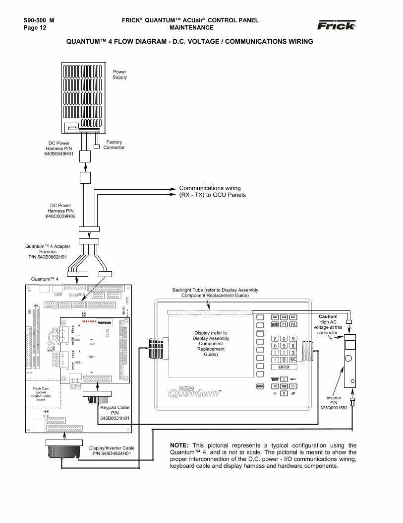
QUANTUM™ 4 FLOW DIAGRAM - D.C. VOLTAGE / COMMUNICATIONS WIRING
Keypad CableP/N
640B0031H01
Quantum™ 4
InverterP/N
333Q0001582
Quantum™ 4 AdapterHarness
P/N 649B0862H01
NOTE: This pictorial represents a typical configuration using theQuantum™ 4, and is not to scale. The pictorial is meant to show theproper interconnection of the D.C. power - I/O communications wiring,keyboard cable and display harness and hardware components.
Display/Inverter CableP/N 649D4824H01
P
P
Flash Cardsocket
located underboard
1
2
3
4
3 2 1
3
1
2
4
Backlight Tube (refer to Display AssemblyComponent Replacement Guide)
)
Display (refer toDisplay Assembly
ComponentReplacement
Guide)
Caution!High AC
voltage at thisconnector.
DC PowerHarness P/N
640C0039H02
PowerSupply
FactoryConnector
Communications wiring(RX - TX) to GCU Panels
DC PowerHarness P/N
640B0049H01
FRICK QUANTUM™ ACUair CONTROL PANEL S90-500 M MAINTENANCE Page 13
GCU (GENERAL CONTROL UNIT) BOARDS
The information that follows in this section can help locateproblems that can occur with GCU Input and Output circuitboards, and their interaction with the Quantum™controller.
GCU Board Description
The GCU Board is actually a small microprocessor boardand programmed to control discrete outputs, or acceptingdiscrete inputs, from external electrical devices. EachBoard has the capability of 16 output channels and 8 Inputchannels. Additionally, there is the capability for 11 Analoginput channels and 4 Analog output channels. With theQuantum™ ACUair® Control, these I/O channels arededicated as to their function, through the operatingsystem (software), enabled options and external wiring.Each channel that is used by the software will have amodule plugged into it. A yellow module indicates that it isused for Inputs. A black module is used for Outputs. Thestandard Quantum™ ACUair® package can have from oneto four GCU Boards in the control network.
Communications LED's
The Quantum™ controller is in constant communicationwith all GCU Boards. You will notice on each GCU board,that there are a pair of LED's that are labeled as RX1 andTX1. These letters represent Receive (RX) and Transmit(TX). These LED's should be flashing at a fairly high rateduring normal operation. This indicates that theQuantum™, and the GCU Board that you are looking at,are properly communicating with each other.
• Reference the “JUMPER AND DIPSWITCHSETTINGS" section later in this manual. Thissection contains the dipswitch settings foraddressing the GCU Boards numbers (1) through(4). When these switches are properly set, theQuantum™ is able to serially communicate witheach GCU board and provide data exchange. Ifthese switches are not properly set, the result willbe lost or failed communications.
Connections to the Quantum™
As stated earlier, the Quantum™ standard ACUair®
control system utilizes up to four GCU Boards (in separateenclosures). To connect all of these boards together sothat the Quantum™ can interface with them, they must beinterconnected with a two-wire cable that provides thecommunications capabilities. These two signals are theRX (receive) and TX (transmit). These signals are themeans by which the Quantum™ communicates to theGCU.
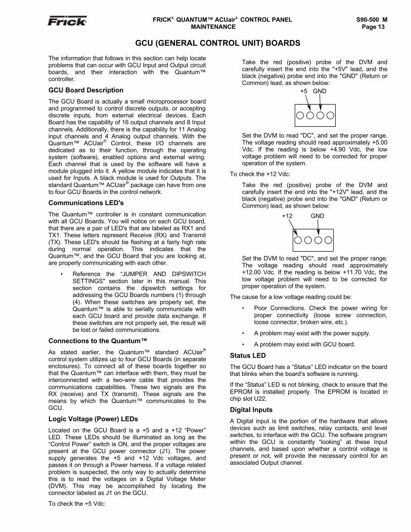
Logic Voltage (Power) LEDs
Located on the GCU Board is a +5 and a +12 “Power”LED. These LEDs should be illuminated as long as the“Control Power” switch is ON, and the proper voltages arepresent at the GCU power connector (J1). The powersupply generates the +5 and +12 Vdc voltages, andpasses it on through a Power harness. If a voltage relatedproblem is suspected, the only way to actually determinethis is to read the voltages on a Digital Voltage Meter(DVM). This may be accomplished by locating theconnector labeled as J1 on the GCU.
To check the +5 Vdc:
Take the red (positive) probe of the DVM andcarefully insert the end into the "+5V" lead, and theblack (negative) probe end into the "GND" (Return orCommon) lead, as shown below:
Set the DVM to read "DC", and set the proper range.The voltage reading should read approximately +5.00Vdc. If the reading is below +4.90 Vdc, the lowvoltage problem will need to be corrected for properoperation of the system.
To check the +12 Vdc:
Take the red (positive) probe of the DVM andcarefully insert the end into the "+12V" lead, and theblack (negative) probe end into the "GND" (Return orCommon) lead, as shown below:
Set the DVM to read "DC", and set the proper range.The voltage reading should read approximately+12.00 Vdc. If the reading is below +11.70 Vdc, thelow voltage problem will need to be corrected forproper operation of the system.
The cause for a low voltage reading could be:
• Poor Connections. Check the power wiring forproper connectivity (loose screw connection,loose connector, broken wire, etc.).
• A problem may exist with the power supply.
• A problem may exist with GCU board.
Status LED
The GCU Board has a “Status” LED indicator on the boardthat blinks when the board’s software is running.
If the “Status” LED is not blinking, check to ensure that theEPROM is installed properly. The EPROM is located inchip slot U22.
Digital Inputs
A Digital input is the portion of the hardware that allowsdevices such as limit switches, relay contacts, and levelswitches, to interface with the GCU. The software programwithin the GCU is constantly “looking” at these Inputchannels, and based upon whether a control voltage ispresent or not, will provide the necessary control for anassociated Output channel.
+5 GND
+12 GND

S90-500 M FRICK QUANTUM™ ACUair CONTROL PANELPage 14 MAINTENANCE
Input modules are yellow in color. A side profile of thismodule is shown below:
Digital Outputs
A Digital Output is the portion of the hardware that theGCU is to control (energize). These devices includesolenoids, relay coils, fans, blower contactors and heatersto be energized, based upon the logic within the GCUsoftware program.
Output modules are black in color. A side profile of thismodule is shown below:
Although this Output module is labeled as 280 VAC on thetop, and on the side, it can be used on 120 applications.
Never plug an Input module into a position designated foran Output module.
You will notice that when a module is plugged into theGCU Board, there is a fuse located directly adjacent to themodule. This fuse is of the plugable variety, and may beremove for testing.
Checking the Digital Inputs and Outputs
Some problems that may be encountered involvetroubleshooting the digital inputs and outputs. The DigitalGCU has three Digital I/O (DIO) board connectors labeledJ7, J9 and J10. All digital I/O are wired to theseconnectors.
J10 (Input) - Positions 1, 3, 5, 7, 9, 11, 13, and 15 areNeutral connections. Positions 2, 4, 6, 8, 10, 12, 14,and 16 are 120 Vac signal inputs:
J9 (Output) - Positions 1, 3, 5, 7, 9, 11, 13, and 15are 120 Vac Hot connections. Positions 2, 4, 6, 8, 10,12, 14, and 16 are 120 Vac signal inputs:
J7 (Output) - Positions 1, 3, 5, 7, 9, 11, 13, and 15are 120 Vac Hot connections. Positions 2, 4, 6, 8, 10,12, 14, and 16 are 120 Vac signal inputs:
An LED is associated with each module and displays thestate of each module. A lighted LED represents an Inputthat is “High”, receiving a signal or an Output that is “On”.
If a properly configured GCU board is not respondingcorrectly, first look at the GCU board on the “ServiceScreen”. It is possible that one or more modules (input oroutput) has a problem:
For an Output - If the screen says that an output ison, there should be 120 volts at the terminal strip forthe corresponding output (refer to the wiringdiagrams). If it is not on, check the LED on the GCUBoard for the suspect output module. It should be lit. Ifthe LED is not lit, then check the fuse for the output(inputs do not have fuses). If the output fuse is OK,then check the module.
For an Input - If you know for a fact that a particularinput should be energized, but the screen shows it asbeing off, then verify at the field wiring terminal stripthe presence of 120 volts (refer to the wiringdiagrams). If voltage is present at the terminal strip,then measure voltage at the GCU board inputterminal strip (J10). Refer to the diagram on this pagethat shows the J10 terminal strip to identify whichposition is used for each input. If there is voltage tothe GCU terminal (J10), then replace thecorresponding input module.
Fuse Testing and Replacement
1. Power off the panel.
2. Open the panel door.
3. Remove the questionable fuse.
4. Check the fuse using a DVM.
5. If the fuse is faulty, check for external shorts onthe corresponding circuit, then replace the fusewith a new plug-type fuse (refer toRecommended Spare Parts list).
5-
4+
3+
COM OUT VDC5VDC LOGIC
2∼
1
90-140VACAC INPUT
120 VAC Input
4-
3+
3-8 VDCDC CONTROL
2∼
1
3A 280VACAC OUTPUT
120 VAC Output
116
N
Input1
Input2
Input3
Input4
Input5
Input6
Input7
Input8
116
H
Output1
Output2
Output3
Output4
Output5
Output6
Output7
Output8
116
H
Output9
Output10
Output11
Output12
Output13
Output14
Ouput15
Output16

FRICK QUANTUM™ ACUair CONTROL PANEL S90-500 M MAINTENANCE Page 15
Input and Output Module Testing andReplacement
1. Power off the panel.
2. Open the panel door.
3. Replace the questionable module.
4. Power on the panel.
5. If it is an Input module, check if the associatedLED is on when power is applied to the module.
Troubleshooting an Output
1. Make sure the LED associated with the Output ison when power is applied to the module.
2. If the LED is not on when it should be and thereis no operating condition preventing it, contactthe Frick® Service Department.
3. If the LED is on when it should be, check forproper panel voltage on the DIO connector plug.Check the voltage between neutral, and theassociated signal position of the Output module.
4. If the voltage is OK, check for proper panelvoltage between the associated signal position ofthe Output module on the DIO connector and theassociated position on the terminal strip.
5. If the voltage is OK, check the wiring external tothe panel.
6. If voltage is not OK, check the fuse.
7. If the fuse is OK, then check the module.
8. If the module is OK, check for proper panelvoltage on the DIO connector plug between theoutput signal position, and neutral.
Troubleshooting an Input
1. Make sure the LED associated with the Input ison when power is applied to the module.
2. If the LED is on then the Input module is good.
3. If the LED is on and there is no input voltage,replace the Input module.
Replacing a Defective GCU Board
The procedure to replace a GCU board is outlined below:
1. Shut off control power.
2. Remove the old board from the machine and thenew board from its packing and place both on ananti-static surface.
3. Remove any required chip(s) from the defectiveboard and install them in the replacement board.Align the notch at the end of the EPROM with thenotch in the socket.
• Ensure that the GCU EPROM (installed intoU22) has the proper label affixed to it. TheVersion number should match between allGCU EPROMS, as well as the programversion of the Quantum (as shown on the“About…”screen). As an example, if theQuantum version is 2.1, then all GCU boardsmust have version 2.1. The GCU boardsmay have an additional digit in the versionnumber, such as 2.11. This final digit is notcritical with the compatibility of the system.
4. Ensure that all jumpers, dip switches, I/Omodules and components are properly setup onthe new board as it was on the old board.
5. Install the modified replacement board in thepanel.
After replacing a GCU board, it will automatically bedetected after the Quantum power has been cycled offthen on. It will then be necessary to re-enter all setpointsand calibration data to the board. Refer to the FactorySetup Instructions for more information (S90-500 FSI).
S90-500 M FRICK QUANTUM™ ACUair CONTROL PANELPage 16 MAINTENANCE
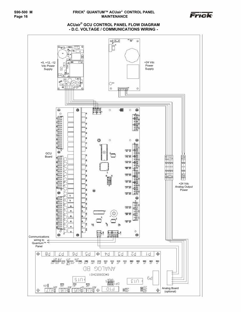
ACUair® GCU CONTROL PANEL FLOW DIAGRAM- D.C. VOLTAGE / COMMUNICATIONS WIRING -
GCUBoard
Analog Board(optional)
+5, +12, -12Vdc Power
Supply
+24 VdcPowerSupply
+24 VdcAnalog Output
Power
Communicationswiring to
Quantum™Panel
FRICK QUANTUM™ ACUair CONTROL PANEL S90-500 M MAINTENANCE Page 17
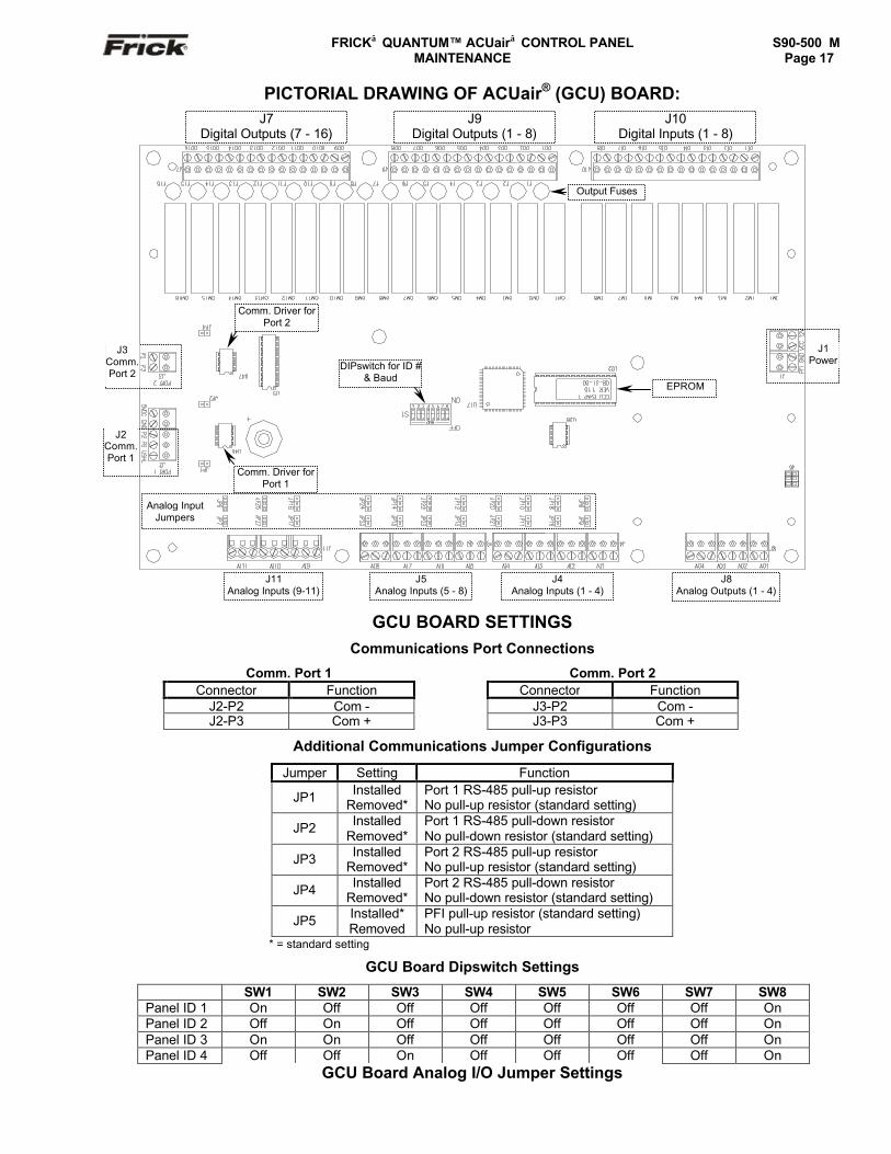
PICTORIAL DRAWING OF ACUair® (GCU) BOARD:
GCU BOARD SETTINGSCommunications Port Connections
Comm. Port 1 Comm. Port 2Connector Function Connector Function
J2-P2 Com - J3-P2 Com -J2-P3 Com + J3-P3 Com +
Additional Communications Jumper Configurations
Jumper Setting Function
JP1 InstalledRemoved*
Port 1 RS-485 pull-up resistorNo pull-up resistor (standard setting)
JP2 InstalledRemoved*
Port 1 RS-485 pull-down resistorNo pull-down resistor (standard setting)
JP3 InstalledRemoved*
Port 2 RS-485 pull-up resistorNo pull-up resistor (standard setting)
JP4 InstalledRemoved*
Port 2 RS-485 pull-down resistorNo pull-down resistor (standard setting)
JP5 Installed*Removed
PFI pull-up resistor (standard setting)No pull-up resistor
* = standard setting
GCU Board Dipswitch Settings
SW1 SW2 SW3 SW4 SW5 SW6 SW7 SW8Panel ID 1 On Off Off Off Off Off Off OnPanel ID 2 Off On Off Off Off Off Off OnPanel ID 3 On On Off Off Off Off Off OnPanel ID 4 Off Off On Off Off Off Off On
GCU Board Analog I/O Jumper Settings
J3Comm.Port 2
J2Comm.Port 1
EPROM
Comm. Driver forPort 1
Comm. Driver forPort 2
DIPswitch for ID #& Baud
J1Power
J8Analog Outputs (1 - 4)
J11Analog Inputs (9-11)
J5Analog Inputs (5 - 8)
J4Analog Inputs (1 - 4)
Output Fuses
J7Digital Outputs (7 - 16)
J9Digital Outputs (1 - 8)
J10Digital Inputs (1 - 8)
Analog InputJumpers
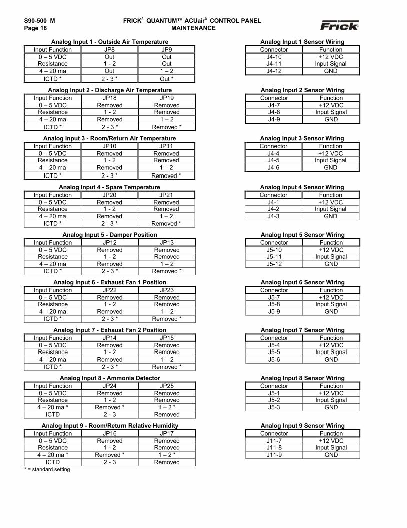
S90-500 M FRICK QUANTUM™ ACUair CONTROL PANELPage 18 MAINTENANCE
Analog Input 1 - Outside Air Temperature Analog Input 1 Sensor WiringInput Function JP8 JP9 Connector Function
0 – 5 VDC Out Out J4-10 +12 VDCResistance 1 - 2 Out J4-11 Input Signal4 – 20 ma Out 1 – 2 J4-12 GND
ICTD * 2 - 3 * Out *
Analog Input 2 - Discharge Air Temperature Analog Input 2 Sensor WiringInput Function JP18 JP19 Connector Function
0 – 5 VDC Removed Removed J4-7 +12 VDCResistance 1 - 2 Removed J4-8 Input Signal4 – 20 ma Removed 1 – 2 J4-9 GND
ICTD * 2 - 3 * Removed *
Analog Input 3 - Room/Return Air Temperature Analog Input 3 Sensor WiringInput Function JP10 JP11 Connector Function
0 – 5 VDC Removed Removed J4-4 +12 VDCResistance 1 - 2 Removed J4-5 Input Signal4 – 20 ma Removed 1 – 2 J4-6 GND
ICTD * 2 - 3 * Removed *
Analog Input 4 - Spare Temperature Analog Input 4 Sensor WiringInput Function JP20 JP21 Connector Function
0 – 5 VDC Removed Removed J4-1 +12 VDCResistance 1 - 2 Removed J4-2 Input Signal4 – 20 ma Removed 1 – 2 J4-3 GND
ICTD * 2 - 3 * Removed *
Analog Input 5 - Damper Position Analog Input 5 Sensor WiringInput Function JP12 JP13 Connector Function
0 – 5 VDC Removed Removed J5-10 +12 VDCResistance 1 - 2 Removed J5-11 Input Signal4 – 20 ma Removed 1 – 2 J5-12 GND
ICTD * 2 - 3 * Removed *
Analog Input 6 - Exhaust Fan 1 Position Analog Input 6 Sensor WiringInput Function JP22 JP23 Connector Function
0 – 5 VDC Removed Removed J5-7 +12 VDCResistance 1 - 2 Removed J5-8 Input Signal4 – 20 ma Removed 1 – 2 J5-9 GND
ICTD * 2 - 3 * Removed *
Analog Input 7 - Exhaust Fan 2 Position Analog Input 7 Sensor WiringInput Function JP14 JP15 Connector Function
0 – 5 VDC Removed Removed J5-4 +12 VDCResistance 1 - 2 Removed J5-5 Input Signal4 – 20 ma Removed 1 – 2 J5-6 GND
ICTD * 2 - 3 * Removed *
Analog Input 8 - Ammonia Detector Analog Input 8 Sensor WiringInput Function JP24 JP25 Connector Function
0 – 5 VDC Removed Removed J5-1 +12 VDCResistance 1 - 2 Removed J5-2 Input Signal4 – 20 ma * Removed * 1 – 2 * J5-3 GND
ICTD 2 - 3 Removed
Analog Input 9 - Room/Return Relative Humidity Analog Input 9 Sensor WiringInput Function JP16 JP17 Connector Function
0 – 5 VDC Removed Removed J11-7 +12 VDCResistance 1 - 2 Removed J11-8 Input Signal4 – 20 ma * Removed * 1 – 2 * J11-9 GND
ICTD 2 - 3 Removed* = standard setting
FRICK QUANTUM™ ACUair CONTROL PANEL S90-500 M MAINTENANCE Page 19
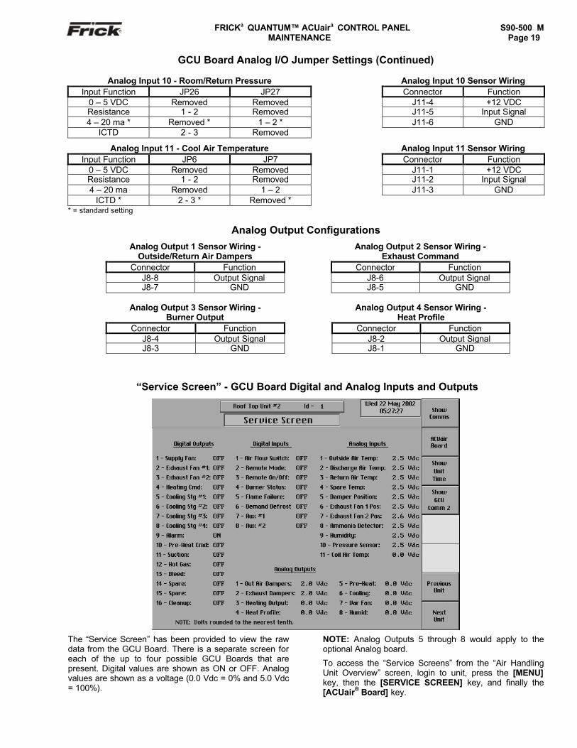
GCU Board Analog I/O Jumper Settings (Continued)
Analog Input 10 - Room/Return Pressure Analog Input 10 Sensor WiringInput Function JP26 JP27 Connector Function
0 – 5 VDC Removed Removed J11-4 +12 VDCResistance 1 - 2 Removed J11-5 Input Signal4 – 20 ma * Removed * 1 – 2 * J11-6 GND
ICTD 2 - 3 Removed
Analog Input 11 - Cool Air Temperature Analog Input 11 Sensor WiringInput Function JP6 JP7 Connector Function
0 – 5 VDC Removed Removed J11-1 +12 VDCResistance 1 - 2 Removed J11-2 Input Signal4 – 20 ma Removed 1 – 2 J11-3 GND
ICTD * 2 - 3 * Removed ** = standard setting
Analog Output Configurations
Analog Output 1 Sensor Wiring -Outside/Return Air Dampers
Analog Output 2 Sensor Wiring -Exhaust Command
Connector Function Connector FunctionJ8-8 Output Signal J8-6 Output SignalJ8-7 GND J8-5 GND
Analog Output 3 Sensor Wiring -Burner Output
Analog Output 4 Sensor Wiring -Heat Profile
Connector Function Connector FunctionJ8-4 Output Signal J8-2 Output SignalJ8-3 GND J8-1 GND
“Service Screen” - GCU Board Digital and Analog Inputs and Outputs
The “Service Screen” has been provided to view the rawdata from the GCU Board. There is a separate screen foreach of the up to four possible GCU Boards that arepresent. Digital values are shown as ON or OFF. Analogvalues are shown as a voltage (0.0 Vdc = 0% and 5.0 Vdc= 100%).
NOTE: Analog Outputs 5 through 8 would apply to theoptional Analog board.
To access the “Service Screens” from the “Air HandlingUnit Overview” screen, login to unit, press the [MENU]key, then the [SERVICE SCREEN] key, and finally the[ACUair® Board] key.
S90-500 M FRICK QUANTUM™ ACUair CONTROL PANELPage 20 MAINTENANCE
ANALOG BOARD
The optional Analog board would be installed in a GCUcontrol enclosure only when the installed options call for it.
The information that follows in this section can help locateproblems that can occur with Analog Input and Outputcircuit board, and their interaction with the GCU Board.
Analog Board Description
The Analog Board is actually a small microprocessorboard and is programmed to control analog outputs, oraccepting inputs, from external electrical devices. EachAnalog Board has the capability of 16 independentchannels or I/O (Input/Output). With the GCU ACUair®
Control, these I/O channels are dedicated, through thesoftware and external wring, as to the function of eachchannel. Each channel that is used by the software willhave to be configured for the type of device that isconnected to it (4-20 mA, 0-5 v, 1-5 v, or ICTD). Thestandard GCU ACUair® control can have up to one Analogboard (depending on options).
• Reference the “JUMPER AND DIPSWITCHSETTINGS” section later in this section. Thissection contains the dipswitch settings foraddressing the Analog I/O Board. When theseswitches are properly set, the GCU board is ableto serially communicate with the Analog I/Oboard and provide control signals and dataexchange. If these switches are not properly set,the result will be one of the following:
• The wrong analog input signals beingreceived
• The wrong analog output signals being sentfrom the board.
Connections to the Quantum™
As stated earlier, the GCU ACUair® control system utilizesone Analog Board. To connect this board so that the GCUcan provide control, it must be interconnected with a wiringharness that provides all of the necessary D.C. voltagerequirements, as well as the communications capabilities.A diagram of this wiring harness can be found later in thismanual (see the ACUair® GCU Control Panel FlowDiagram - D.C. Voltage / Communications Wiring). Thisharness has a 16-pin connector at one end, which plugsinto the Analog board. The other end has no connector,and simply wires directly into the DC power terminalsmounted on the right hand side of the GCU enclosure, andComm Port 2 (J3) of the GCU board.
Analog Inputs
An Analog Input is the portion of the hardware that allowsdevices such as temperature sensors and pressuretransducers, ammonia detectors, etc., to interface with theGCU. The software program within the GCU is constantly“looking” at these Input channels (throughcommunications) and based upon what the voltage orcurrent level of the channel is, will provide the necessarycontrol for an associated action.
Analog inputs arrive at the board on connectors P1through P8. Each of these connectors can receive twochannels (for a total of sixteen).Each of the sixteen analog input channels is boardconfigurable to select for the following input signals:
• 4-20 mA
• 0-5 volt
• 1-5 volt
• ICTD
Refer to the Analog Board drawing and Analog BoardSettings pages that appear later in this section for specificinformation and locations of jumpers. Also, see the sectionentitled “Checking the Analog Inputs and Outputs”.
Analog Outputs
An Analog Output is the portion of the hardware that theGCU uses to provide control. With ACUair®, this output istypically a 4-20 mA signal that is outputted to an externaldevice. The devices are:
• Pre-Heat
• Cooling
• Variable Speed Fan
• Humidity
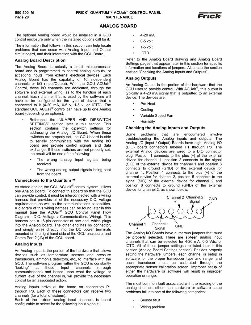
Checking the Analog Inputs and Outputs
Some problems that are encountered involvetroubleshooting the Analog inputs and outputs. TheAnalog I/O (Input / Output) Boards have eight Analog I/O(DIO) board connectors labeled P1 through P8. Theexternal Analog devices are wired to a DIO connectorplug. Position 1 connects to the plus (+) of the externaldevice for channel 1, position 2 connects to the signal(SIG) of the external device for channel 1 and position 3connects to ground (GND) of the external device forchannel 1. Position 4 connects to the plus (+) of theexternal device for channel 2, position 5 connects to thesignal (SIG) of the external device for channel 2 andposition 6 connects to ground (GND) of the externaldevice for channel 2, as shown below:
The Analog I/O Boards have numerous jumpers that mustbe properly selected. There are sixteen analog inputchannels that can be selected for 4-20 mA, 0-5 Vdc, orICTD. All of these jumper settings are listed later in thissection (Analog Board Settings section). Besides properlysetting the hardware jumpers, each channel is setup insoftware for the proper transducer type and range, andeach transducer must be calibrated through theappropriate sensor calibration screen. Improper setup ofeither the hardware or software will result in improperoperation or range.
The most common fault associated with the reading of theanalog channels other than hardware or software setupproblems fall into one of the following categories:
• Sensor fault
• Wiring problem
GND
Channel 2+
Channel 1+
Channel 1Signal
Channel 2Signal
GND

FRICK QUANTUM™ ACUair CONTROL PANEL S90-500 M MAINTENANCE Page 21
• Improper grounding of system.
An open wire, shorted wire, or faulty sensor will usuallygive a reading at either the minimum or the maximum endof the range scale. An erratic reading or a reading thatseems to float up and down is usually indicative of agrounding problem. When a single transducer or cable isshorted to earth (or system) ground, this can show up as awhole assortment of problem channels. The easiest wayto find a short to earth problem is to disconnect all thesensor plugs and ohm out each plug screw terminal toearth for open (infinite) impedance. All sensors shouldread open to earth.
Replacing a Defective Analog Board
The procedure to replace the Analog board is outlinedbelow:
1. Shut off control power.
2. Remove the old board from the machine and thenew board from its packing and place both on ananti-static surface.
3. Remove any required chip(s) from the defectiveboard and install them in the replacement board.
4. Check that all jumpers, dipswitches andcomponents are properly setup on the new boardas it was on the old board.
5. Install the modified replacement board in thepanel.
ANALOG BOARD SETTINGS
Communications Settings
J33in
out*
RS-422/485 receive pull-down for longcommunications lines.No pull-down
J34in
out*
RS-422/485 transmit pull-up for longcommunications lines.No pull-up.
J35in
out*
RS-422 receive pull-down for longcommunications lines.No pull-down.
J36in
out*
RS-422 transmit pull-up for longcommunications lines.No pull-up.
J37in
out*
120 ohm long communications linetermination.No termination.
* standard setting
Dipswitch Settings
SW1 SW2 SW3 SW4 SW5Board #1 On * On * On * On * Off *Board #2 Off On On On OffBoard #3 On Off On On OffBoard #4 Off Off On On OffBoard #5 On On Off On OffBoard #6 Off On Off On Off
* standard setting
Analog Board Output Jumpers
Output Channel #1 - Pre-Heat **
J26 1-22-3*
0-20 mA Output4-20 mA Output
J39 1-2*2-3
4-20 mA Output0-20 mA Output
IC’s install U15 & U7 Connect to P10 terms 1 & 2
Output Channel #2 - Cooling **
J25 1-22-3*
0-20 mA Output4-20 mA Output
J40 1-2*2-3
4-20 mA Output0-20 mA Output
IC’s install U15 & U6 Connect to P10 terms 3 & 4
Output Channel #3 - Variable Speed Fan **
J24 1-22-3*
0-20 mA Output4-20 mA Output
J41 1-2*2-3
4-20 mA Output0-20 mA Output
IC’s install U15 & U5 Connect to P10 terms 5 & 6
Output Channel #4 – Humidity **
J23 1-22-3*
0-20 mA Output4-20 mA Output
J42 1-2*2-3
4-20 mA Output0-20 mA Output
IC’s install U15 & U4 Connect to P10 terms 7 & 8* = Standard Setting** = If applicable
Note: IC’s must also be installed in order to enable theanalog output options. U15 along with at least one IC(U4, U5, U6 or U7) installed will enable the channel.

S90-500 M FRICK QUANTUM™ ACUair CONTROL PANELPage 22 MAINTENANCE
ADDITIONAL SERVICE RELATED SCREENSGCU “About” Screen
This “About” screen shows the GCU Board softwareversion for the GCU board that is currently selected.
To access the GCU “About” screen from the “Air HandlingUnit Overview” screen, login to unit, press the [MENU]key, then the [ABOUT…] key.
Quantum™ “About” Screen
This “About” screen shows the Quantum™ softwareversion.
To access the Quantum™ “About” screen from the “AirHandling Unit Overview” screen, press the [Panel Status]key, then the [ABOUT…] key.

FRICK QUANTUM™ ACUair CONTROL PANEL S90-500 M MAINTENANCE Page 23
“Change Communications” Screen
The following screen selections are provided:[Service Screen] - Press this key to access the"Show Comms" screen. Use this screen to view theASCII communications that is occurring on the COM1and COM2 communications port.
[Change Setpoints] - Select this key to change thepanel ID number.[Change to 38400 Baud] - A toggle key that changesbetween the baud rates of 1200, 2400, 4800, 9600,19200, 38400, 76800, and 115200 is provided for theComm. 1 setup. [Change to 38400 Baud] - A toggle key thatchanges between the baud rates of 1200, 2400, 4800,
9600, 19200, 38400, 76800, and 115200 is providedfor the Comm. 2 setup.
[A-B Comm.] - This is a toggle key that provides amethod of selecting one protocol to communicate tothe panel. This key changes between enabling A-B(Allen-Bradley), Modbus, or Frick® communicationprotocol. For further setup, see the S90-500(Communications Setup manual).
[Remote] - A toggle key that changes betweenRemote and Manual for the Panel Control Status.
To access the “Change Communications” screen from the“Air Handling Unit Overview” screen, press the [PanelSetup] key, then the [Change Comms] key.
S90-500 M FRICK QUANTUM™ ACUair CONTROL PANELPage 24 MAINTENANCE
QUANTUM™ POWER SUPPLY ADJUSTMENT AND REPLACEMENTADJUSTMENT
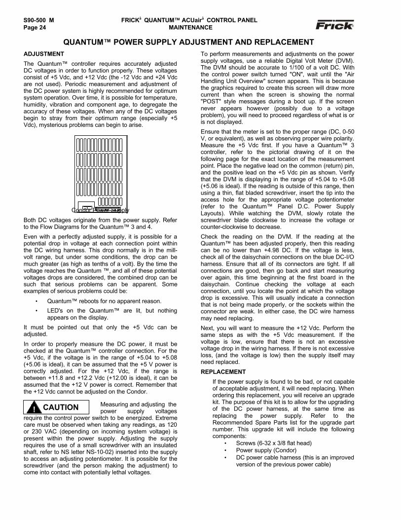
The Quantum™ controller requires accurately adjustedDC voltages in order to function properly. These voltagesconsist of +5 Vdc, and +12 Vdc (the -12 Vdc and +24 Vdcare not used). Periodic measurement and adjustment ofthe DC power system is highly recommended for optimumsystem operation. Over time, it is possible for temperature,humidity, vibration and component age, to degregate theaccuracy of these voltages. When any of the DC voltagesbegin to stray from their optimum range (especially +5Vdc), mysterious problems can begin to arise.
Condor Power Supply
Both DC voltages originate from the power supply. Referto the Flow Diagrams for the Quantum™ 3 and 4.
Even with a perfectly adjusted supply, it is possible for apotential drop in voltage at each connection point withinthe DC wiring harness. This drop normally is in the mill-volt range, but under some conditions, the drop can bemuch greater (as high as tenths of a volt). By the time thevoltage reaches the Quantum ™, and all of these potentialvoltages drops are considered, the combined drop can besuch that serious problems can be apparent. Someexamples of serious problems could be:
• Quantum™ reboots for no apparent reason.
• LED's on the Quantum™ are lit, but nothingappears on the display.
It must be pointed out that only the +5 Vdc can beadjusted.
In order to properly measure the DC power, it must bechecked at the Quantum™ controller connection. For the+5 Vdc, if the voltage is in the range of +5.04 to +5.08(+5.06 is ideal), it can be assumed that the +5 V power iscorrectly adjusted. For the +12 Vdc, if the range isbetween +11.8 and +12.2 Vdc (+12.00 is ideal), it can beassumed that the +12 V power is correct. Remember thatthe +12 Vdc cannot be adjusted on the Condor.
Measuring and adjusting thepower supply voltages
require the control power switch to be energized. Extremecare must be observed when taking any readings, as 120or 230 VAC (depending on incoming system voltage) ispresent within the power supply. Adjusting the supplyrequires the use of a small screwdriver with an insulatedshaft, refer to NS letter NS-10-02) inserted into the supplyto access an adjusting potentiometer. It is possible for thescrewdriver (and the person making the adjustment) tocome into contact with potentially lethal voltages.
To perform measurements and adjustments on the powersupply voltages, use a reliable Digital Volt Meter (DVM).The DVM should be accurate to 1/100 of a volt DC. Withthe control power switch turned "ON", wait until the "AirHandling Unit Overview" screen appears. This is becausethe graphics required to create this screen will draw morecurrent than when the screen is showing the normal"POST" style messages during a boot up. If the screennever appears however (possibly due to a voltageproblem), you will need to proceed regardless of what is oris not displayed.
Ensure that the meter is set to the proper range (DC, 0-50V, or equivalent), as well as observing proper wire polarity.Measure the +5 Vdc first. If you have a Quantum™ 3controller, refer to the pictorial drawing of it on thefollowing page for the exact location of the measurementpoint. Place the negative lead on the common (return) pin,and the positive lead on the +5 Vdc pin as shown. Verifythat the DVM is displaying in the range of +5.04 to +5.08(+5.06 is ideal). If the reading is outside of this range, thenusing a thin, flat bladed screwdriver, insert the tip into theaccess hole for the appropriate voltage potentiometer(refer to the Quantum™ Panel D.C. Power SupplyLayouts). While watching the DVM, slowly rotate thescrewdriver blade clockwise to increase the voltage orcounter-clockwise to decrease.
Check the reading on the DVM. If the reading at theQuantum™ has been adjusted properly, then this readingcan be no lower than +4.98 DC. If the voltage is less,check all of the daisychain connections on the blue DC-I/Oharness. Ensure that all of its connectors are tight. If allconnections are good, then go back and start measuringover again, this time beginning at the first board in thedaisychain. Continue checking the voltage at eachconnection, until you locate the point at which the voltagedrop is excessive. This will usually indicate a connectionthat is not being made properly, or the sockets within theconnector are weak. In either case, the DC wire harnessmay need replacing.
Next, you will want to measure the +12 Vdc. Perform thesame steps as with the +5 Vdc measurement. If thevoltage is low, ensure that there is not an excessivevoltage drop in the wiring harness. If there is not excessiveloss, (and the voltage is low) then the supply itself mayneed replaced.
REPLACEMENT
If the power supply is found to be bad, or not capableof acceptable adjustment, it will need replacing. Whenordering this replacement, you will receive an upgradekit. The purpose of this kit is to allow for the upgradingof the DC power harness, at the same time asreplacing the power supply. Refer to theRecommended Spare Parts list for the upgrade partnumber. This upgrade kit will include the followingcomponents:
• Screws (6-32 x 3/8 flat head)• Power supply (Condor)• DC power cable harness (this is an improved
version of the previous power cable)
CAUTION!
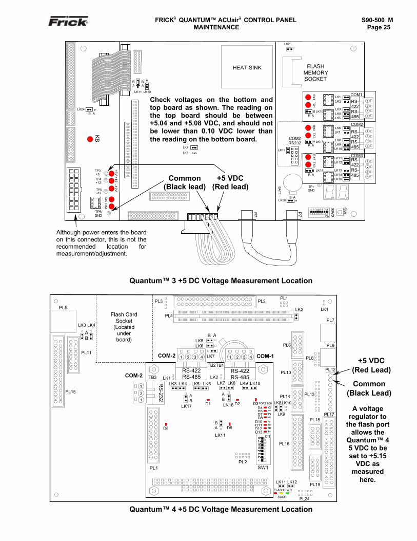
FRICK QUANTUM™ ACUair CONTROL PANEL S90-500 M MAINTENANCE Page 25
Quantum™ 3 +5 DC Voltage Measurement Location
Quantum™ 4 +5 DC Voltage Measurement Location
KB
COM2
TP3+5
TP4+12
TP5-12
RX
4TX
4
TP6GND
LK11
BA
LK10
BA
LK7
LK8
LK24B A
HEAT SINK
COM2RS232
LK19
FLASHMEMORYSOCKET
SW
BA
T1
SW
2
ON
1 2 3 4 5 6 7 8
LK20B A
P7
P7
TP1GND
COM31
2
3
4
RS-422RS-485
LK12LK11
LK13LK14LK15
TX3
RX
3
LK18B A
B A
1
2
3
4
RS-422RS-485
LK6
LK8LK9LK10
LK7TX2
RX
2
LK17
COM1LK1LK2
LK3LK4LK5
1
2
3
4
RS-422RS-485
LK16B A
TX1
RX
1
LK25
-12V+5V
+12 +5 VDC(Red lead)
Common(Black lead)
Although power enters the boardon this connector, this is not therecommended location formeasurement/adjustment.
Check voltages on the bottom andtop board as shown. The reading onthe top board should be between+5.04 and +5.08 VDC, and should notbe lower than 0.10 VDC lower thanthe reading on the bottom board.
Check voltages on the bottom andtop board as shown. The reading onthe top board should be between+5.04 and +5.08 VDC, and should notbe lower than 0.10 VDC lower thanthe reading on the bottom board.
PL13
LK9
LK8LK10
PL16
PL8
PWR
SUSP
FLASH
LK11 LK12
PL24
PL3
PL
LK1
PL7
PL9
LK2
PL17
PL12
PL19
PL18
PL14
PL10
PL6
PL2
PL4
PL1
Flash CardSocket
(Locatedunderboard)
PL3PL5
PL11
LK3
AB
LK4
PL15
TB1TB2
LK2COM-2 TB3
RS
-232
321
LK6
B ALK5
LK7COM-2 COM-11 2 3 4 1 2 3 4
LK8LK7 LK10LK9
D3LK16
AB
AB
PL2
34
56
70
12
D8D10D11D12
PORT 80H
D4D5D7
D13
SW1
ON
1 2
3 4
5 6
7 8
D6
D2
LK11
BA
LK1LK4LK3 LK6LK5
D1
D8
LK17
RS-422RS-485
RS-422RS-485
PL1
+5 VDC(Red Lead)
Common(Black Lead)
A voltageregulator to
the flash portallows the
Quantum™ 45 VDC to beset to +5.15
VDC asmeasured
here.
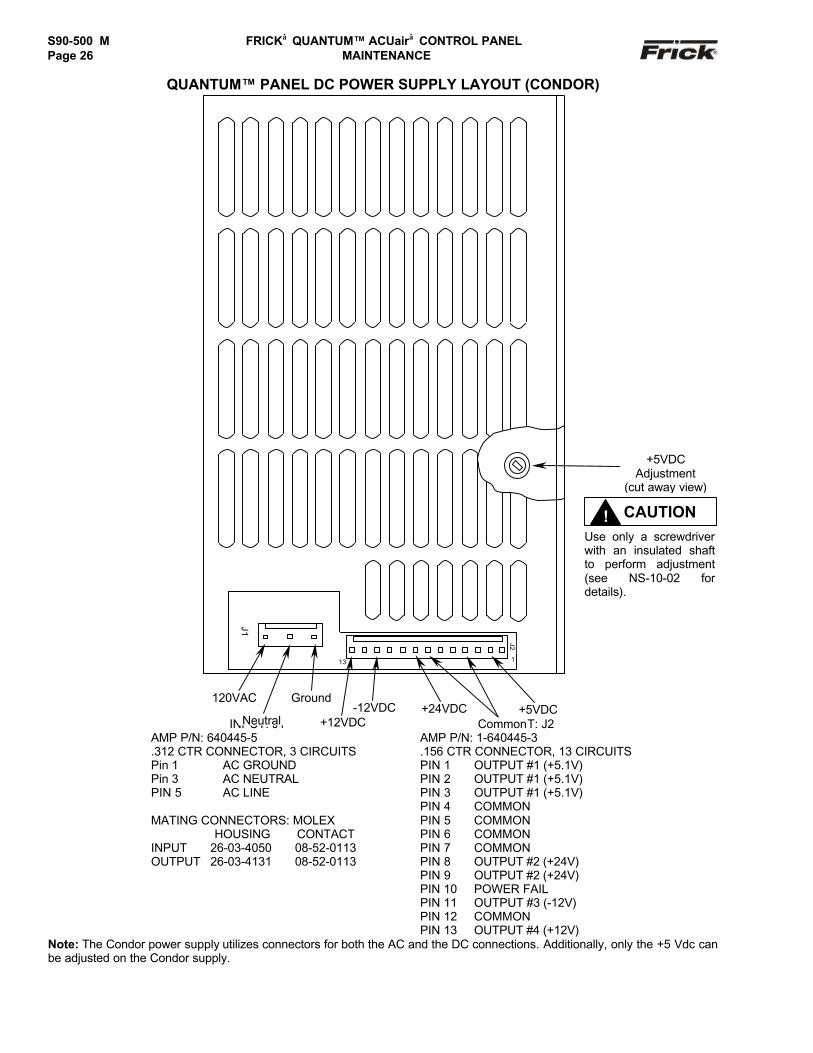
S90-500 M FRICK QUANTUM™ ACUair CONTROL PANELPage 26 MAINTENANCE
QUANTUM™ PANEL DC POWER SUPPLY LAYOUT (CONDOR)
INPUT: J1 INPUT: J2AMP P/N: 640445-5.312 CTR CONNECTOR, 3 CIRCUITS
AMP P/N: 1-640445-3.156 CTR CONNECTOR, 13 CIRCUITS
Pin 1 AC GROUND PIN 1 OUTPUT #1 (+5.1V)Pin 3 AC NEUTRAL PIN 2 OUTPUT #1 (+5.1V)PIN 5 AC LINE PIN 3 OUTPUT #1 (+5.1V)
PIN 4 COMMONPIN 5 COMMONPIN 6 COMMONPIN 7 COMMONPIN 8 OUTPUT #2 (+24V)PIN 9 OUTPUT #2 (+24V)PIN 10 POWER FAILPIN 11 OUTPUT #3 (-12V)PIN 12 COMMON
MATING CONNECTORS: MOLEX HOUSING CONTACTINPUT 26-03-4050 08-52-0113OUTPUT 26-03-4131 08-52-0113
PIN 13 OUTPUT #4 (+12V)Note: The Condor power supply utilizes connectors for both the AC and the DC connections. Additionally, only the +5 Vdc canbe adjusted on the Condor supply.
+5VDCAdjustment
(cut away view)
120VAC
Neutral
Ground+5VDC
Common+24VDC-12VDC
+12VDC
J1
J2
113
CAUTION!Use only a screwdriverwith an insulated shaftto perform adjustment(see NS-10-02 fordetails).
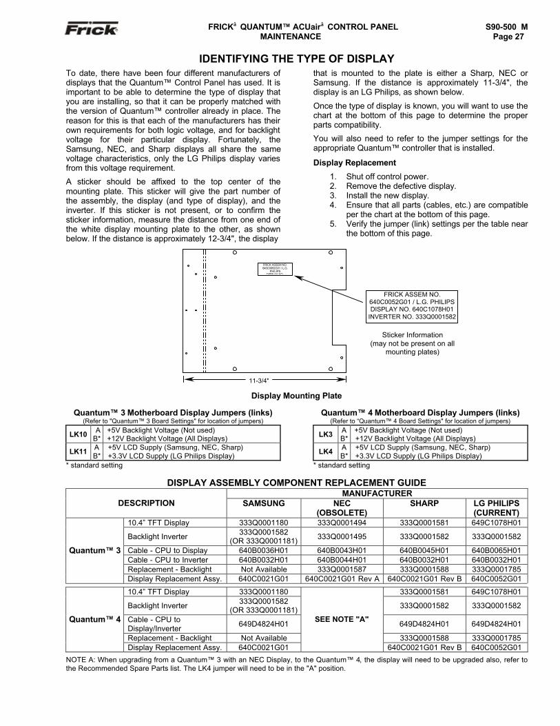
FRICK QUANTUM™ ACUair CONTROL PANEL S90-500 M MAINTENANCE Page 27
IDENTIFYING THE TYPE OF DISPLAYTo date, there have been four different manufacturers ofdisplays that the Quantum™ Control Panel has used. It isimportant to be able to determine the type of display thatyou are installing, so that it can be properly matched withthe version of Quantum™ controller already in place. Thereason for this is that each of the manufacturers has theirown requirements for both logic voltage, and for backlightvoltage for their particular display. Fortunately, theSamsung, NEC, and Sharp displays all share the samevoltage characteristics, only the LG Philips display variesfrom this voltage requirement.
A sticker should be affixed to the top center of themounting plate. This sticker will give the part number ofthe assembly, the display (and type of display), and theinverter. If this sticker is not present, or to confirm thesticker information, measure the distance from one end ofthe white display mounting plate to the other, as shownbelow. If the distance is approximately 12-3/4", the display
that is mounted to the plate is either a Sharp, NEC orSamsung. If the distance is approximately 11-3/4", thedisplay is an LG Philips, as shown below.
Once the type of display is known, you will want to use thechart at the bottom of this page to determine the properparts compatibility.
You will also need to refer to the jumper settings for theappropriate Quantum™ controller that is installed.
Display Replacement
1. Shut off control power.2. Remove the defective display.3. Install the new display.4. Ensure that all parts (cables, etc.) are compatible
per the chart at the bottom of this page.5. Verify the jumper (link) settings per the table near
the bottom of this page.
Display Mounting Plate
Quantum™ 3 Motherboard Display Jumpers (links)(Refer to "Quantum™ 3 Board Settings" for location of jumpers)
LK10 AB*
+5V Backlight Voltage (Not used)+12V Backlight Voltage (All Displays)
LK11 AB*
+5V LCD Supply (Samsung, NEC, Sharp)+3.3V LCD Supply (LG Philips Display)
* standard setting
Quantum™ 4 Motherboard Display Jumpers (links)(Refer to “Quantum™ 4 Board Settings" for location of jumpers)
LK3 AB*
+5V Backlight Voltage (Not used)+12V Backlight Voltage (All Displays)
LK4 AB*
+5V LCD Supply (Samsung, NEC, Sharp)+3.3V LCD Supply (LG Philips Display)
* standard setting
DISPLAY ASSEMBLY COMPONENT REPLACEMENT GUIDEMANUFACTURER
DESCRIPTION SAMSUNG NEC(OBSOLETE)
SHARP LG PHILIPS(CURRENT)
10.4” TFT Display 333Q0001180 333Q0001494 333Q0001581 649C1078H01
Backlight Inverter 333Q0001582(OR 333Q0001181) 333Q0001495 333Q0001582 333Q0001582
Cable - CPU to Display 640B0036H01 640B0043H01 640B0045H01 640B0065H01Cable - CPU to Inverter 640B0032H01 640B0044H01 640B0032H01 640B0032H01Replacement - Backlight Not Available 333Q0001587 333Q0001588 333Q0001785
Quantum™ 3
Display Replacement Assy. 640C0021G01 640C0021G01 Rev A 640C0021G01 Rev B 640C0052G01
10.4” TFT Display 333Q0001180 333Q0001581 649C1078H01
Backlight Inverter 333Q0001582(OR 333Q0001181) 333Q0001582 333Q0001582
Cable - CPU toDisplay/Inverter 649D4824H01 649D4824H01 649D4824H01
Replacement - Backlight Not Available 333Q0001588 333Q0001785
Quantum™ 4
Display Replacement Assy. 640C0021G01
SEE NOTE "A"
640C0021G01 Rev B 640C0052G01
NOTE A: When upgrading from a Quantum™ 3 with an NEC Display, to the Quantum™ 4, the display will need to be upgraded also, refer tothe Recommended Spare Parts list. The LK4 jumper will need to be in the "A" position.
11-3/4"
FRICK ASSEM NO.640C0052G01 / L.G.
PHILIPSDISPLAY NO.
FRICK ASSEM NO.640C0052G01 / L.G. PHILIPSDISPLAY NO. 640C1078H01
INVERTER NO. 333Q0001582
Sticker Information(may not be present on all
mounting plates)
S90-500 M FRICK QUANTUM™ ACUair CONTROL PANELPage 28 MAINTENANCE
TROUBLESHOOTING A PROBLEM THAT APPEARS UNEXPLAINABLE
When there is a problem that makes no sense due tounexplainable things happening, then check the following:
� It is important to know if the unit ever workedproperly.
� If the unit used to work properly, try to determinewhen the problem first showed up.
� It is important to know if the problem occursrandomly, frequently, or all the time.
� Check what the temperature is at the panel. Is itvery hot or very cold?
� If it just started to act up, then check if there wasrecently a severe lightning storm, fire, flood, or aplant accident. If any of the following conditionsare possible, then check for it:
� Has any water or oil leaked into the panel orconduit?
� If it just started to act up, then check if anythingwas recently changed in the system (i.e. softwareor hardware.)
� If it just started to act up, then check if anyservice was recently done to the air unit or it’selectrical system?
� If there is communication wiring connecting thepanel to another panel or device, then check thefollowing:
� If the Quantum™ is unexplainably shuttingdown, try disconnecting the communicationscable to see if the problem goes away (thisdoes not affect the individual air unitsoperation).
� Check if the communications cable shieldsare tied to machine ground at only onelocation.
� Check that you are using the Frick®
recommended communications cable. Seemanual to match proper cable with type ofcommunications (i.e., RS-422, RS-232, RS-485, or some other type of factorycommunication bus system.)
� If this is an older plant, has the plant wiring beenbrought up to code?
� Do you have power wiring mixed with controlwiring?
� Do you have power wiring mixed with sensorwiring?
� Do you have power wiring mixed withcommunications wiring?
� Check that the starter panel is grounded to theplant transformer. There are usually four wires: 3
for the 3 phases and 1 for plant ground.
� Check that the motor is grounded to the starterpanel. There are usually four wires: 3 for thephases and 1 for ground.
� Check that the pressure transducers are properlygrounded. The two types of transducers you mayhave are as follows: an older type has an 8 to 10inch 3-conductor pigtail coming out of thetransducer. This type will have the attachingcable’s shield cut off and insulated at thetransducer end. The shield is then tied to a panelground terminal in the panel. The newer type hasthe cable as an integral part of the housing andhas the shield crimped to the case at thetransducer end. This type of transducer has thecable’s shield cut off and insulated in the controlpanel.
� Check that the temperature transducers areproperly grounded. The temperature probesusually have two short wires coming out of thesensor, and are tied to a shielded cable at thethermal well head. The shield is insulated at thetemperature probe and grounded at the panelend.
� Check if one of the temperature probes has asignal wire shorted to machine ground. To dothis, first pull the orange plug from the microboard and then use a DVM and check each whitewire to machine ground and each black wire tomachine ground.
� Check that all inductive loads (i.e. Coils,Solenoids, or Relays, etc.) connected to the I/Ooutput modules have surge suppressers acrossthem, preferably at the devices and not at thepanel end.
� If the air unit control settings unexplainablychange modes, it may be a noise problemaffecting the keypad’s input circuit. Check if itworks OK with the keypad cable disconnected. Ifit works OK, then check the grounding asdescribed above. If the grounding is OK thenreplace the keypad.
� Make sure that you have a continuous groundback to the power source. The ground connectionmust be aluminum or copper. A conduit groundwill not work.
� Make sure that there is no AC wiring lying next tothe printed circuit board.
� Unexplainable auxiliary failures are usuallyindicative of noise due to wiring problems (i.e.incorrect earth grounds, mixed power and controlwiring, unsuppressed coils, etc)

FRICK QUANTUM™ ACUair CONTROL PANEL S90-500 M MAINTENANCE Page 29
SETPOINT DATA SHEETSIn most cases, updating software on the Quantum™ panel will require clearing the current setpoints and data stored in thenonvolatile memory on the main board. It is suggested that the operator first record all control setpoints prior to performingprogram chip upgrades. Panel Setup and Factory Setup settings will be lost when software is updated. The setpoint datasheets are useful for recording this information.
The ACUair® product consists of either of two types of air handling units, Makeup Air, or Mixed Air. Because of the twoavailable types, this section will address each type separately, as each may have different setup screens based upon theinstalled options. Be aware that not all of the items shown here may be depicted on your individual unit. These screens are anattempt at showing all possible options that can be enabled.
CONTROL SETUP
Setting Default RangeProcess Control Setpoint ______ 35.1° F 0.0° F – 100.1° F
Cleanup Heating setpoint ______ 42.1° F -40.0° F - 167.0° F
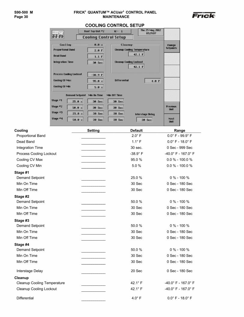
S90-500 M FRICK QUANTUM™ ACUair CONTROL PANELPage 30 MAINTENANCE
COOLING CONTROL SETUP
Cooling Setting Default RangeProportional Band ____________ 2.0° F 0.0° F - 99.9° F
Dead Band ____________ 1.1° F 0.0° F - 18.0° F
Integration Time ____________ 30 sec. 0 Sec - 999 Sec
Process Cooling Lockout ____________ -38.9° F -40.0° F - 167.0° F
Cooling CV Max ____________ 95.0 % 0.0 % - 100.0 %
Cooling CV Min ____________ 5.0 % 0.0 % - 100.0 %
Stage #1Demand Setpoint ____________ 25.0 % 0 % - 100 %
Min On Time ____________ 30 Sec 0 Sec - 180 Sec
Min Off Time ____________ 30 Sec 0 Sec - 180 Sec
Stage #2Demand Setpoint ____________ 50.0 % 0 % - 100 %
Min On Time ____________ 30 Sec 0 Sec - 180 Sec
Min Off Time ____________ 30 Sec 0 Sec - 180 Sec
Stage #3Demand Setpoint ____________ 50.0 % 0 % - 100 %
Min On Time ____________ 30 Sec 0 Sec - 180 Sec
Min Off Time ____________ 30 Sec 0 Sec - 180 Sec
Stage #4Demand Setpoint ____________ 50.0 % 0 % - 100 %
Min On Time ____________ 30 Sec 0 Sec - 180 Sec
Min Off Time ____________ 30 Sec 0 Sec - 180 Sec
Interstage Delay ____________ 20 Sec 0 Sec - 180 Sec
CleanupCleanup Cooling Temperature ____________ 42.1° F -40.0° F - 167.0° F
Cleanup Cooling Lockout ____________ 42.1° F -40.0° F - 167.0° F
Differential ____________ 4.0° F 0.0° F - 18.0° F
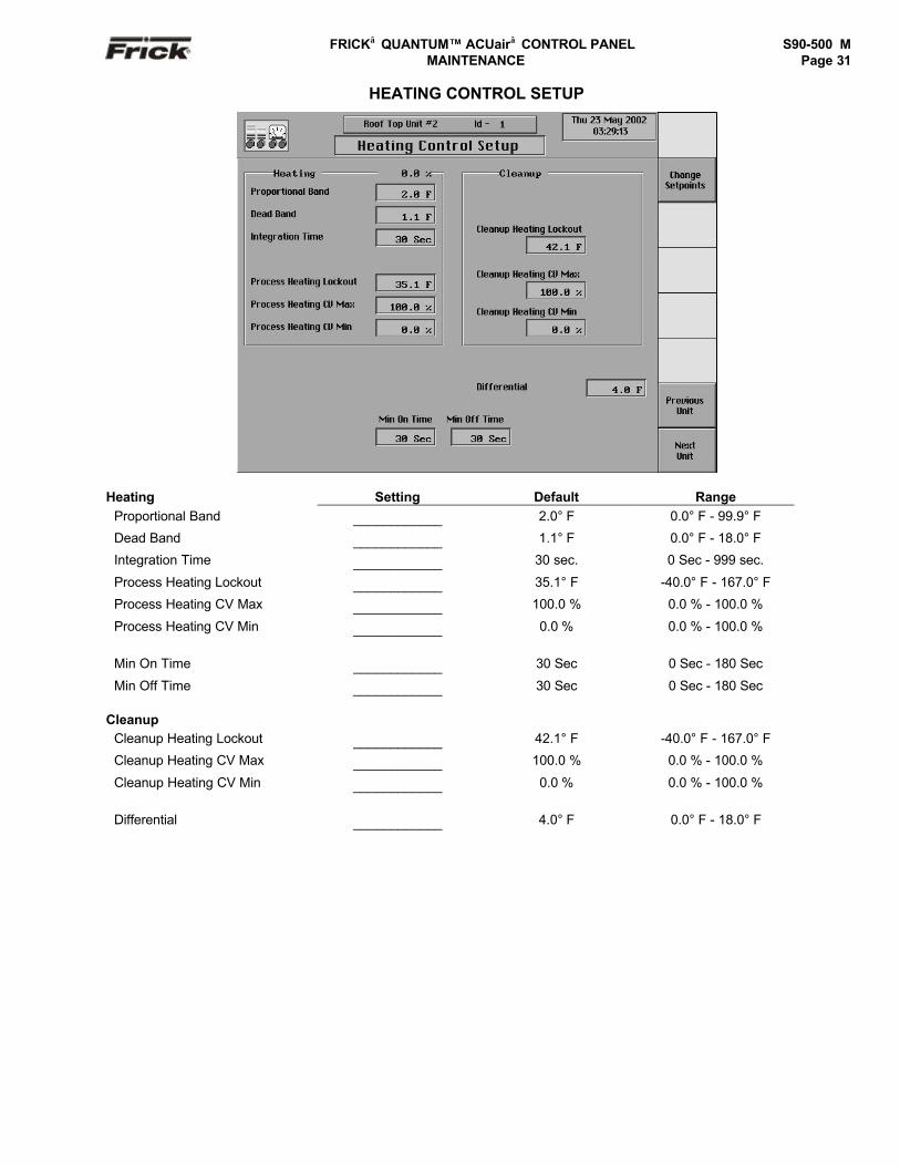
FRICK QUANTUM™ ACUair CONTROL PANEL S90-500 M MAINTENANCE Page 31
HEATING CONTROL SETUP
Heating Setting Default RangeProportional Band ____________ 2.0° F 0.0° F - 99.9° F
Dead Band ____________ 1.1° F 0.0° F - 18.0° F
Integration Time ____________ 30 sec. 0 Sec - 999 sec.
Process Heating Lockout ____________ 35.1° F -40.0° F - 167.0° F
Process Heating CV Max ____________ 100.0 % 0.0 % - 100.0 %
Process Heating CV Min ____________ 0.0 % 0.0 % - 100.0 %
Min On Time ____________ 30 Sec 0 Sec - 180 Sec
Min Off Time ____________ 30 Sec 0 Sec - 180 Sec
CleanupCleanup Heating Lockout ____________ 42.1° F -40.0° F - 167.0° F
Cleanup Heating CV Max ____________ 100.0 % 0.0 % - 100.0 %
Cleanup Heating CV Min ____________ 0.0 % 0.0 % - 100.0 %
Differential ____________ 4.0° F 0.0° F - 18.0° F

S90-500 M FRICK QUANTUM™ ACUair CONTROL PANELPage 32 MAINTENANCE
PRE-HEAT CONTROL SETUP
Pre-Heat Setting Default RangeProportional Band ____________ 2.0° F 0.0° F - 99.9° F
Dead Band ____________ 1.1° F 0.0° F - 18.0° F
Integration Time ____________ 30 sec. 0 Sec - 999 sec.
Pre-Heat Process Setpoint ____________ 35.1° F -40.0° F - 167.0° F
Pre-Heat Process Lockout ____________ 35.1° F -40.0° F - 167.0° F
Pre-Heat Process CV Max ____________ 100.0 % 0.0 % - 100.0 %
Pre-Heat Process CV Min ____________ 0.0 % 0.0 % - 100.0 %
Min On Time ____________ 30 Sec 0 Sec - 180 Sec
Min Off Time ____________ 30 Sec 0 Sec - 180 Sec
CleanupCleanup Pre-Heat Lockout ____________ 42.1° F -40.0° F - 167.0° F
Cleanup Pre-Heat CV Max ____________ 100.0 % 0.0 % - 100.0 %
Cleanup Pre-Heat CV Min ____________ 0.0 % 0.0 % - 100.0 %
Differential ____________ 4.0° F 0.0° F - 18.0° F

FRICK QUANTUM™ ACUair CONTROL PANEL S90-500 M MAINTENANCE Page 33
EXHAUST CONTROL SETUP
Stage #1 Setting Default Range
Start ____________ 35.0 % 0.0 % - 100.0 %
Differential ____________ 3.0 % 0.0% - 10.0 %
Start Enable ____________ 30.0 % 0.0% - 100.0 %
Stage #2Start ____________ 70.0 % 0.0 % - 100.0 %
Differential ____________ 3.0 % 0.0% - 10.0 %
Start Enable ____________ 30.0 % 0.0% - 100.0 %
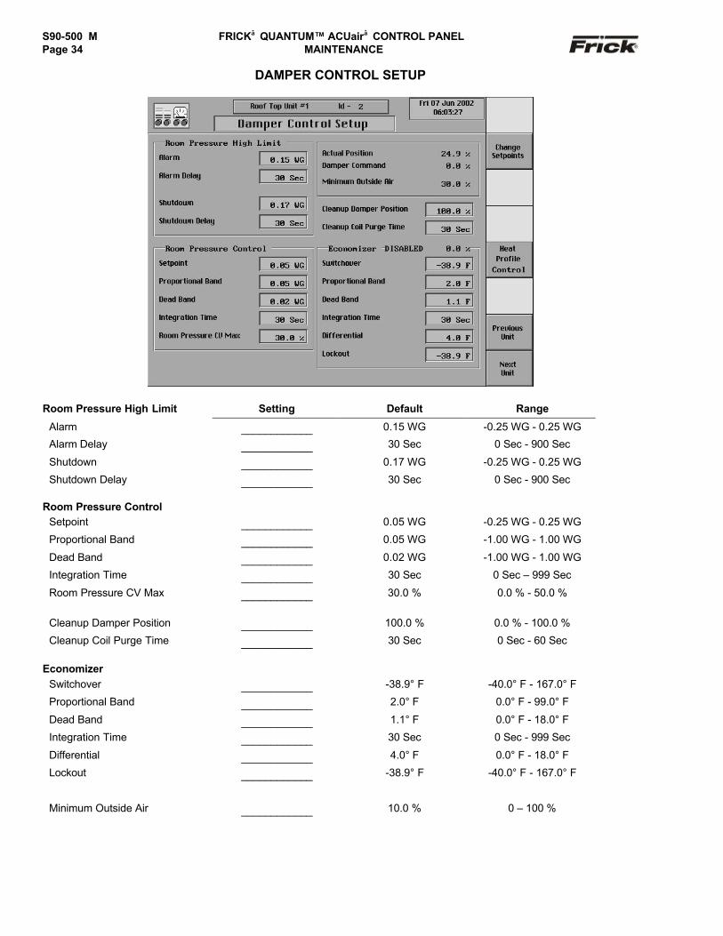
S90-500 M FRICK QUANTUM™ ACUair CONTROL PANELPage 34 MAINTENANCE
DAMPER CONTROL SETUP
Room Pressure High Limit Setting Default Range
Alarm ____________ 0.15 WG -0.25 WG - 0.25 WG
Alarm Delay ____________ 30 Sec 0 Sec - 900 Sec
Shutdown ____________ 0.17 WG -0.25 WG - 0.25 WG
Shutdown Delay ____________ 30 Sec 0 Sec - 900 Sec
Room Pressure ControlSetpoint ____________ 0.05 WG -0.25 WG - 0.25 WG
Proportional Band ____________ 0.05 WG -1.00 WG - 1.00 WG
Dead Band ____________ 0.02 WG -1.00 WG - 1.00 WG
Integration Time ____________ 30 Sec 0 Sec – 999 Sec
Room Pressure CV Max ____________ 30.0 % 0.0 % - 50.0 %
Cleanup Damper Position ____________ 100.0 % 0.0 % - 100.0 %
Cleanup Coil Purge Time ____________ 30 Sec 0 Sec - 60 Sec
EconomizerSwitchover ____________ -38.9° F -40.0° F - 167.0° F
Proportional Band ____________ 2.0° F 0.0° F - 99.0° F
Dead Band ____________ 1.1° F 0.0° F - 18.0° F
Integration Time ____________ 30 Sec 0 Sec - 999 Sec
Differential ____________ 4.0° F 0.0° F - 18.0° F
Lockout ____________ -38.9° F -40.0° F - 167.0° F
Minimum Outside Air ____________ 10.0 % 0 – 100 %
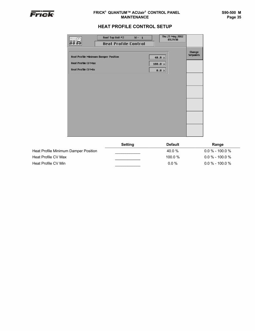
FRICK QUANTUM™ ACUair CONTROL PANEL S90-500 M MAINTENANCE Page 35
HEAT PROFILE CONTROL SETUP
Setting Default Range
Heat Profile Minimum Damper Position ____________ 40.0 % 0.0 % - 100.0 %
Heat Profile CV Max ____________ 100.0 % 0.0 % - 100.0 %
Heat Profile CV Min ____________ 0.0 % 0.0 % - 100.0 %
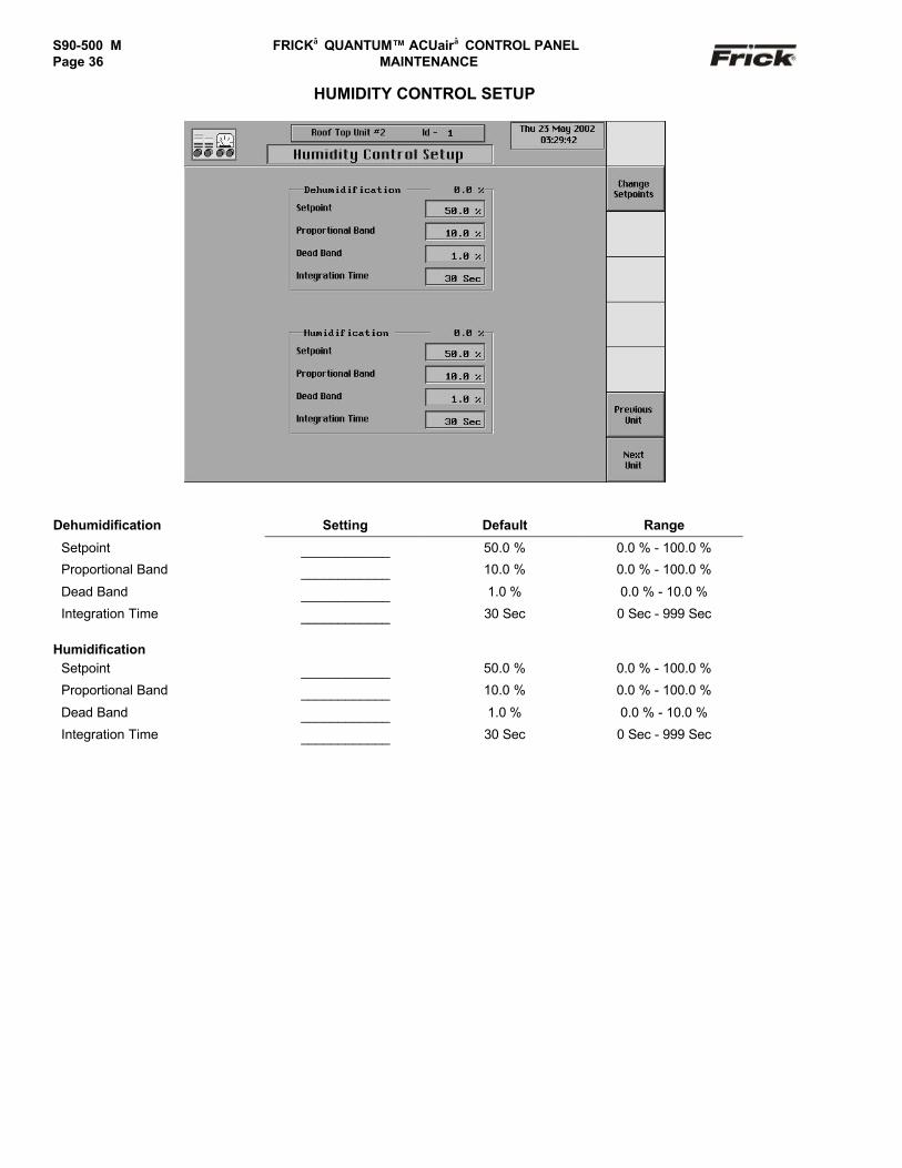
S90-500 M FRICK QUANTUM™ ACUair CONTROL PANELPage 36 MAINTENANCE
HUMIDITY CONTROL SETUP
Dehumidification Setting Default Range
Setpoint ____________ 50.0 % 0.0 % - 100.0 %
Proportional Band ____________ 10.0 % 0.0 % - 100.0 %
Dead Band ____________ 1.0 % 0.0 % - 10.0 %
Integration Time ____________ 30 Sec 0 Sec - 999 Sec
HumidificationSetpoint ____________ 50.0 % 0.0 % - 100.0 %
Proportional Band ____________ 10.0 % 0.0 % - 100.0 %
Dead Band ____________ 1.0 % 0.0 % - 10.0 %
Integration Time ____________ 30 Sec 0 Sec - 999 Sec
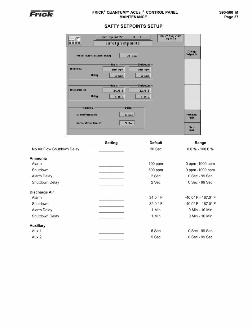
FRICK QUANTUM™ ACUair CONTROL PANEL S90-500 M MAINTENANCE Page 37
SAFTY SETPOINTS SETUP
Setting Default Range
No Air Flow Shutdown Delay ____________ 30 Sec 0.0 % - 100.0 %
AmmoniaAlarm ____________ 100 ppm 0 ppm -1000 ppm
Shutdown ____________ 500 ppm 0 ppm -1000 ppm
Alarm Delay ____________ 2 Sec 0 Sec - 99 Sec
Shutdown Delay ____________ 2 Sec 0 Sec - 99 Sec
Discharge AirAlarm ____________ 34.0 ° F -40.0° F - 167.0° F
Shutdown ____________ 32.0 ° F -40.0° F - 167.0° F
Alarm Delay ____________ 1 Min 0 Min - 10 Min
Shutdown Delay ____________ 1 Min 0 Min - 10 Min
AuxiliaryAux 1 ____________ 5 Sec 0 Sec - 99 Sec
Aux 2 ____________ 5 Sec 0 Sec - 99 Sec

S90-500 M FRICK QUANTUM™ ACUair CONTROL PANELPage 38 MAINTENANCE
DEFROST SETPOINTS SETUP
Defrost Timers Setting Default Range
Pump Out ____________ 3 Min 3 Min - 99 Min
Hot Gas ____________ 20 Min 1 Min - 99 Min
Bleed ____________ 3 Min 3 Min - 99 Min
Fan Delay ____________ 3 Min 2 Min - 99 Min
Defrost Digital InputMax Days Between Defrosts ____________ 3 1 - 99
Max Consecutive Defrosts ____________ 3 1 - 99
Defrost Schedule
Defrost 1 ____________Defrost 2 ____________Defrost 3 ____________Defrost 4 ____________Defrost 5 ____________Defrost 6 ____________Defrost 7 ____________Defrost 8 ____________
Refrig. Counter Setpoint ____________ 0 Min. 0 – 999 Min.

FRICK QUANTUM™ ACUair CONTROL PANEL S90-500 M MAINTENANCE Page 39
AUXILLIARY ANALOG INPUTS (12 & 13) SETUP
Aux. Input #12 Setting Default Range
High Shutdown ____________ 0.0 ° F -273.0° F to 227.0° F
High Shutdown Delay ____________ 0 Sec 0 to 99 Sec
High Alarm ____________ 0.0 ° F -273.0° F to 227.0° F
High Alarm Delay ____________ 0 Sec 0 to 99 Sec
Low Shutdown ____________ 0.0 ° F -273.0° F to 227.0° F
Low Shutdown Delay ____________ 0 Sec 0 to 99 Sec
Low Alarm ____________ 0.0 ° F -273.0° F to 227.0° F
Low Alarm Delay ____________ 0 Sec 0 to 99 Sec
Control: Disabled * Always Active When Running
* Default
Aux. Input #13 Setting Default Range (Based onCalibration)
High Shutdown ____________ 0.0 PSIG -273.0 PSIG to 227.0 PSIG
High Shutdown Delay ____________ 0 Sec 0 to 99 Sec
High Alarm ____________ 0.0 PSIG -273.0 PSIG to 227.0 PSIG
High Alarm Delay ____________ 0 Sec 0 to 99 Sec
Low Shutdown ____________ 0.0 PSIG -273.0 PSIG to 227.0 PSIG
Low Shutdown Delay ____________ 0 Sec 0 to 99 Sec
Low Alarm ____________ 0.0 PSIG -273.0 PSIG to 227.0 PSIG
Low Alarm Delay ____________ 0 Sec 0 to 99 Sec
Control: Disabled * Always Active When Running
* Default

S90-500 M FRICK QUANTUM™ ACUair CONTROL PANELPage 40 MAINTENANCE
AUXILLIARY ANALOG INPUTS (14 & 15) SETUP
Aux. Input #14 Setting Default Range
High Shutdown ____________ 0.0 PSIA -273.0 PSIA to 227.0 PSIA
High Shutdown Delay ____________ 0 Sec 0 to 99 Sec
High Alarm ____________ 0.0 PSIA -273.0 PSIA to 227.0 PSIA
High Alarm Delay ____________ 0 Sec 0 to 99 Sec
Low Shutdown ____________ 0.0 PSIA -273.0 PSIA to 227.0 PSIA
Low Shutdown Delay ____________ 0 Sec 0 to 99 Sec
Low Alarm ____________ 0.0 PSIA -273.0 PSIA to 227.0 PSIA
Low Alarm Delay ____________ 0 Sec 0 to 99 Sec
Control: Disabled * Always Active When Running
* default
Aux. Input #13 Setting Default Range
High Shutdown ____________ 0.0 ppm -273.0 ppm to 227.0 ppm
High Shutdown Delay ____________ 0 Sec 0 to 99 Sec
High Alarm ____________ 0.0 ppm -273.0 ppm to 227.0 ppm
High Alarm Delay ____________ 0 Sec 0 to 99 Sec
Low Shutdown ____________ 0.0 ppm -273.0 ppm to 227.0 ppm
Low Shutdown Delay ____________ 0 Sec 0 to 99 Sec
Low Alarm ____________ 0.0 ppm -273.0 ppm to 227.0 ppm
Low Alarm Delay ____________ 0 Sec 0 to 99 Sec
Control: Disabled * Always Active When Running
* default

FRICK QUANTUM™ ACUair CONTROL PANEL S90-500 M MAINTENANCE Page 41
AUXILLIARY ANALOG OUTPUTS (5, 6, & 7) SETUP
Aux. Output #5 Setting Default Range
Control Input ____________ 1 1 to 15
Aux. Output #6Control Input ____________ 1 1 to 15
Aux. Output #7Control Input ____________ 1 1 to 15
Aux. Output #8Control Input ____________ 1 1 to 15
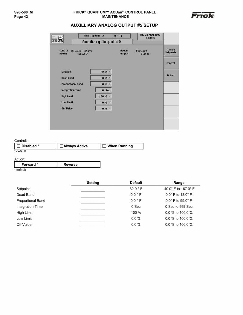
S90-500 M FRICK QUANTUM™ ACUair CONTROL PANELPage 42 MAINTENANCE
AUXILLIARY ANALOG OUTPUT #5 SETUP
Control: Disabled * Always Active When Running
* default
Action: Forward * Reverse
* default
Setting Default Range
Setpoint ____________ 32.0 ° F -40.0° F to 167.0° F
Dead Band ____________ 0.0 ° F 0.0° F to 18.0° F
Proportional Band ____________ 0.0 ° F 0.0° F to 99.0° F
Integration Time ____________ 0 Sec 0 Sec to 999 Sec
High Limit ____________ 100 % 0.0 % to 100.0 %
Low Limit ____________ 0.0 % 0.0 % to 100.0 %
Off Value ____________ 0.0 % 0.0 % to 100.0 %

FRICK QUANTUM™ ACUair CONTROL PANEL S90-500 M MAINTENANCE Page 43
AUXILLIARY ANALOG OUTPUT #6 SETUP
Control: Disabled * Always Active When Running
* default
Action: Forward * Reverse
* default
Setting Default Range
Setpoint ____________ 32.0 ° F -40.0° F to 167.0° F
Dead Band ____________ 0.0 ° F 0.0° F to 18.0° F
Proportional Band ____________ 0.0 ° F 0.0° F to 99.0° F
Integration Time ____________ 0 Sec 0 Sec to 999 Sec
High Limit ____________ 100 % 0.0 % to 100.0 %
Low Limit ____________ 0.0 % 0.0 % to 100.0 %
Off Value ____________ 0.0 % 0.0 % to 100.0 %

S90-500 M FRICK QUANTUM™ ACUair CONTROL PANELPage 44 MAINTENANCE
AUXILLIARY ANALOG OUTPUT #7 SETUP
Control: Disabled * Always Active When Running
* default
Action: Forward * Reverse
* default
Setting Default Range
Setpoint ____________ 32.0 ° F -40.0° F to 167.0° F
Dead Band ____________ 0.0 ° F 0.0° F to 18.0° F
Proportional Band ____________ 0.0 ° F 0.0° F to 99.0° F
Integration Time ____________ 0 Sec 0 Sec to 999 Sec
High Limit ____________ 100 % 0.0 % to 100.0 %
Low Limit ____________ 0.0 % 0.0 % to 100.0 %
Off Value ____________ 0.0 % 0.0 % to 100.0 %

FRICK QUANTUM™ ACUair CONTROL PANEL S90-500 M MAINTENANCE Page 45
AUXILLIARY ANALOG OUTPUT #8 SETUP
Control: Disabled * Always Active When Running
* default
Action: Forward * Reverse
* default
Setting Default Range
Setpoint ____________ 32.0 ° F -40.0° F to 167.0° F
Dead Band ____________ 0.0 ° F 0.0° F to 18.0° F
Proportional Band ____________ 0.0 ° F 0.0° F to 99.0° F
Integration Time ____________ 0 Sec 0 Sec to 999 Sec
High Limit ____________ 100 % 0.0 % to 100.0 %
Low Limit ____________ 0.0 % 0.0 % to 100.0 %
Off Value ____________ 0.0 % 0.0 % to 100.0 %
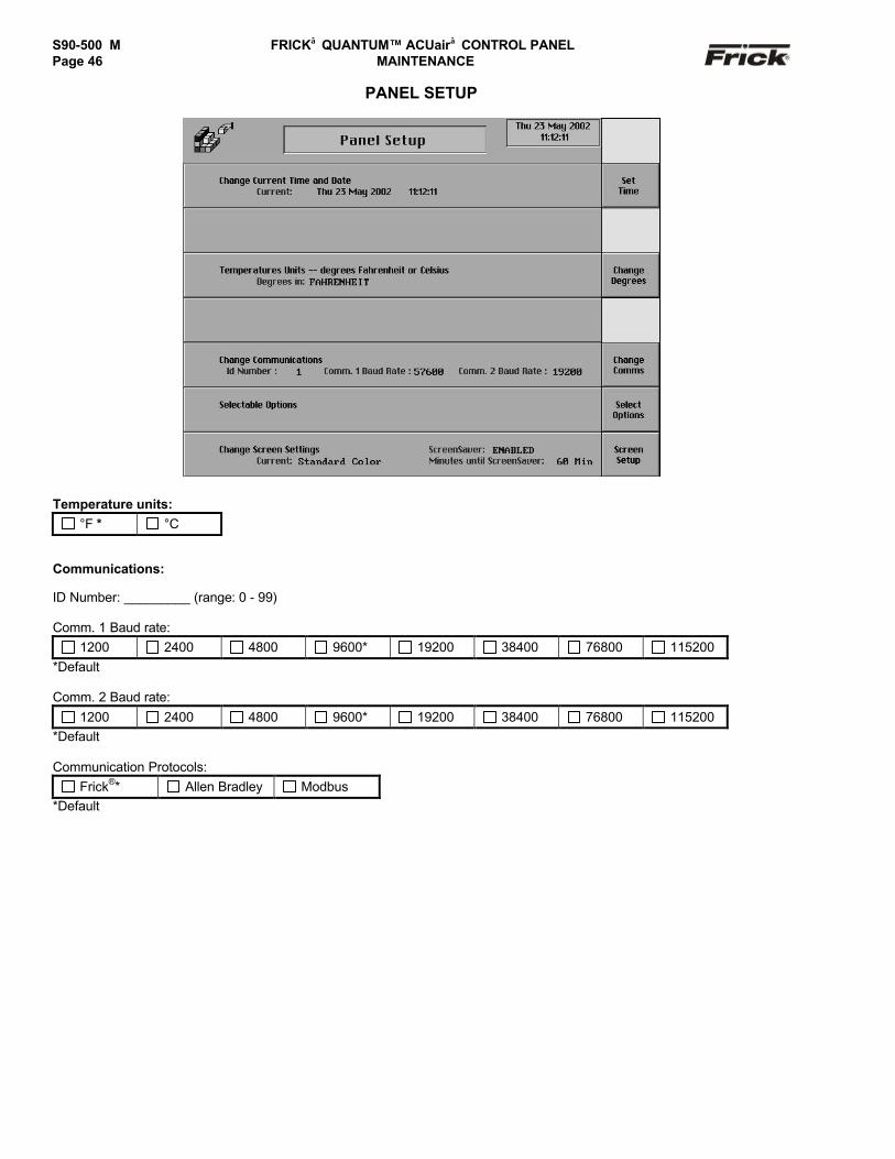
S90-500 M FRICK QUANTUM™ ACUair CONTROL PANELPage 46 MAINTENANCE
PANEL SETUP
Temperature units: °F * °C
Communications:
ID Number: _________ (range: 0 - 99)
Comm. 1 Baud rate: 1200 2400 4800 9600* 19200 38400 76800 115200
*Default
Comm. 2 Baud rate: 1200 2400 4800 9600* 19200 38400 76800 115200
*Default
Communication Protocols: Frick®* Allen Bradley Modbus
*Default

FRICK QUANTUM™ ACUair CONTROL PANEL S90-500 M MAINTENANCE Page 47
SELECTABLE OPTIONS
Selectable Options:
Flash Screen on Shutdown: Enabled Disabled
Remote Control Mode Available: Enabled Disabled
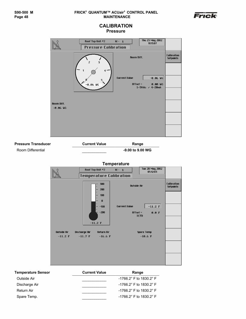
S90-500 M FRICK QUANTUM™ ACUair CONTROL PANELPage 48 MAINTENANCE
CALIBRATIONPressure
Pressure Transducer Current Value Range
Room Differential ____________ -9.00 to 9.00 WG
Temperature
Temperature Sensor Current Value Range
Outside Air ____________ -1766.2° F to 1830.2° F
Discharge Air ____________ -1766.2° F to 1830.2° F
Return Air ____________ -1766.2° F to 1830.2° F
Spare Temp. ____________ -1766.2° F to 1830.2° F

FRICK QUANTUM™ ACUair CONTROL PANEL S90-500 M MAINTENANCE Page 49
Other Calibration
Sensor Current Value Range
Outdoor Damper ____________ -999.0 % to 999.0 %
Exhaust Damper 1 ____________ -999.0 % to 999.0 %
Exhaust Damper 2 ____________ -999.0 % to 999.0 %
Return Air Humidity ____________ -999.0 % to 999.0 %
Ammonia ____________ -999 to 9999
Other Calibration
Analog Input Current Value Range
Auxiliary Input # 12 ____________ -999.0° F to 999.0° F
Auxiliary Input # 13 ____________ -999.0 PSIG to 999.0 PSIG
Auxiliary Input # 14 ____________ -999.0 PSAI to 999.0 PSIA
Auxiliary Input # 15 ____________ -999.0 ppm to 999.0 ppm
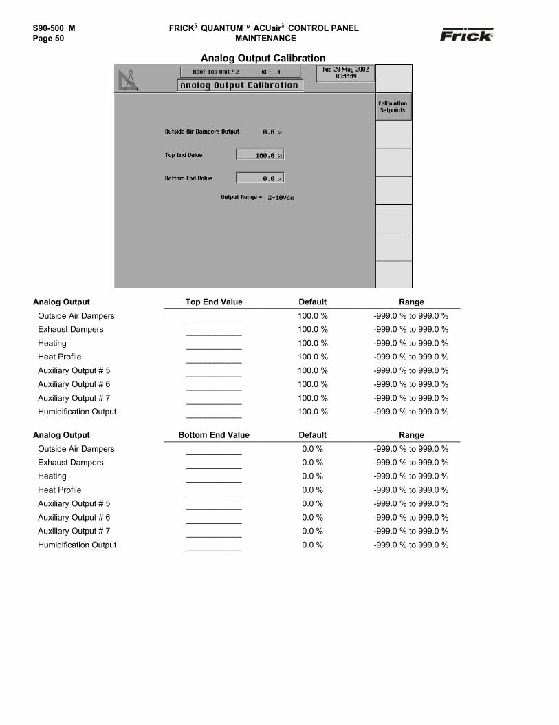
S90-500 M FRICK QUANTUM™ ACUair CONTROL PANELPage 50 MAINTENANCE
Analog Output Calibration
Analog Output Top End Value Default Range
Outside Air Dampers ____________ 100.0 % -999.0 % to 999.0 %
Exhaust Dampers ____________ 100.0 % -999.0 % to 999.0 %
Heating ____________ 100.0 % -999.0 % to 999.0 %
Heat Profile ____________ 100.0 % -999.0 % to 999.0 %
Auxiliary Output # 5 ____________ 100.0 % -999.0 % to 999.0 %
Auxiliary Output # 6 ____________ 100.0 % -999.0 % to 999.0 %
Auxiliary Output # 7 ____________ 100.0 % -999.0 % to 999.0 %
Humidification Output ____________ 100.0 % -999.0 % to 999.0 %
Analog Output Bottom End Value Default Range
Outside Air Dampers ____________ 0.0 % -999.0 % to 999.0 %
Exhaust Dampers ____________ 0.0 % -999.0 % to 999.0 %
Heating ____________ 0.0 % -999.0 % to 999.0 %
Heat Profile ____________ 0.0 % -999.0 % to 999.0 %
Auxiliary Output # 5 ____________ 0.0 % -999.0 % to 999.0 %
Auxiliary Output # 6 ____________ 0.0 % -999.0 % to 999.0 %
Auxiliary Output # 7 ____________ 0.0 % -999.0 % to 999.0 %
Humidification Output ____________ 0.0 % -999.0 % to 999.0 %

FRICK QUANTUM™ ACUair CONTROL PANEL S90-500 M MAINTENANCE Page 51
QUANTUM™ DRAWINGS
This table lists the numbers for the drawings that appear on the following pages. The drawings shown here are the latestrevision as of the printing of this manual. These drawings appear here for reference purposes only, and are subject to changewithout notice. When installing, or servicing equipment, always refer to the actual drawings that are included with the controlpanel for the latest information.
ACUair® Drawings Drawing NumberQuantum™ D.C. Power Supply Harness 640B0049Quantum™ I/O and D.C. Power Supply Harness 640C0039ACUair® Standard Component and Symbol Identification 642D0033ACUair® Standard Control Panel Wiring Diagram and Panel Layout 642D0031
QUANTUM™ D.C. POWER SUPPLY HARNESS
QUANTUM™ I/O & D.C. POWER HARNESS

S90-500 M FRICK QUANTUM™ ACUair CONTROL PANELPage 52 MAINTENANCE
ACUair® STANDARD CONTROL PANEL WIRING DIAGRAM (PAGE 1 OF 9)
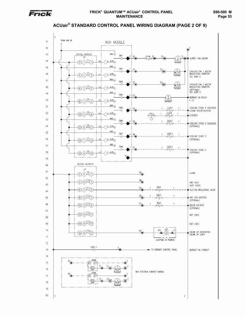
FRICK QUANTUM™ ACUair CONTROL PANEL S90-500 M MAINTENANCE Page 53
ACUair® STANDARD CONTROL PANEL WIRING DIAGRAM (PAGE 2 OF 9)
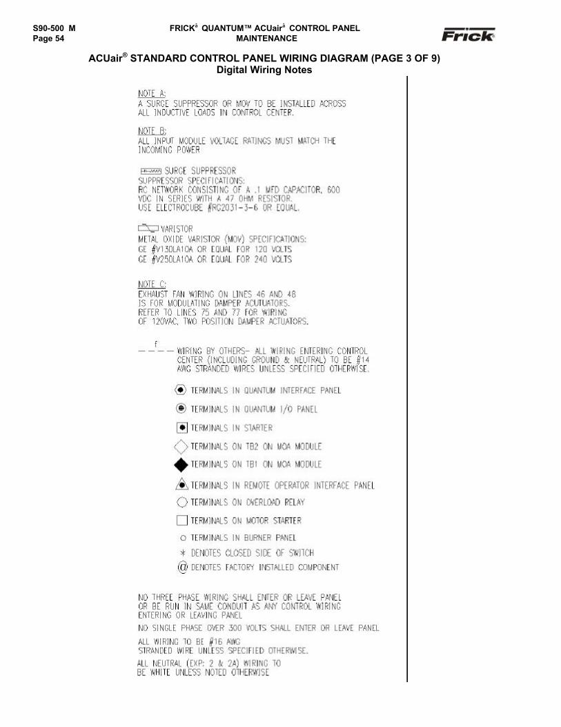
S90-500 M FRICK QUANTUM™ ACUair CONTROL PANELPage 54 MAINTENANCE
ACUair® STANDARD CONTROL PANEL WIRING DIAGRAM (PAGE 3 OF 9)Digital Wiring Notes
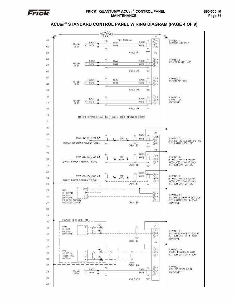
FRICK QUANTUM™ ACUair CONTROL PANEL S90-500 M MAINTENANCE Page 55
ACUair® STANDARD CONTROL PANEL WIRING DIAGRAM (PAGE 4 OF 9)
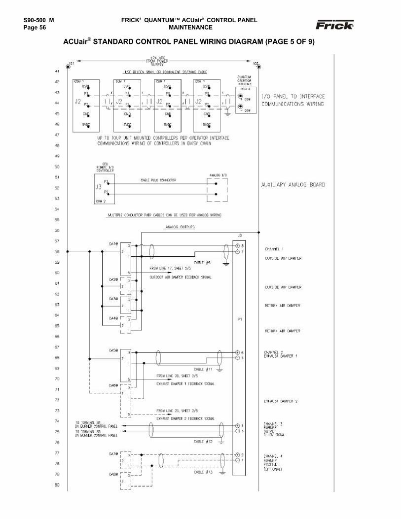
S90-500 M FRICK QUANTUM™ ACUair CONTROL PANELPage 56 MAINTENANCE
ACUair® STANDARD CONTROL PANEL WIRING DIAGRAM (PAGE 5 OF 9)
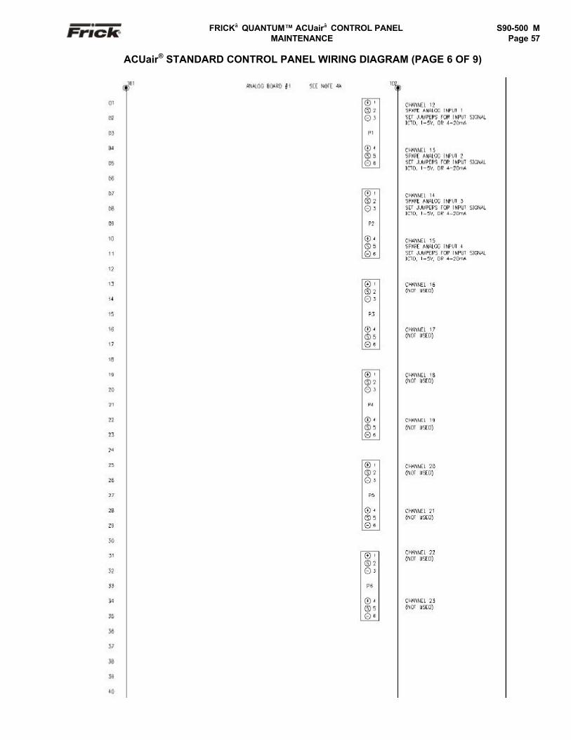
FRICK QUANTUM™ ACUair CONTROL PANEL S90-500 M MAINTENANCE Page 57
ACUair® STANDARD CONTROL PANEL WIRING DIAGRAM (PAGE 6 OF 9)

S90-500 M FRICK QUANTUM™ ACUair CONTROL PANELPage 58 MAINTENANCE
ACUair® STANDARD CONTROL PANEL WIRING DIAGRAM (PAGE 7 OF 9)

FRICK QUANTUM™ ACUair CONTROL PANEL S90-500 M MAINTENANCE Page 59
ACUair® STANDARD GCU CONTROL PANEL WIRING DIAGRAM (PAGE 8 OF 9)Analog Wiring Notes
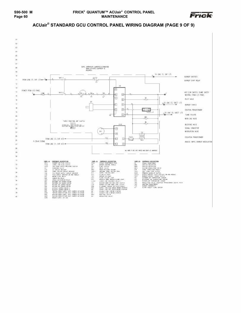
S90-500 M FRICK QUANTUM™ ACUair CONTROL PANELPage 60 MAINTENANCE
ACUair® STANDARD GCU CONTROL PANEL WIRING DIAGRAM (PAGE 9 OF 9)
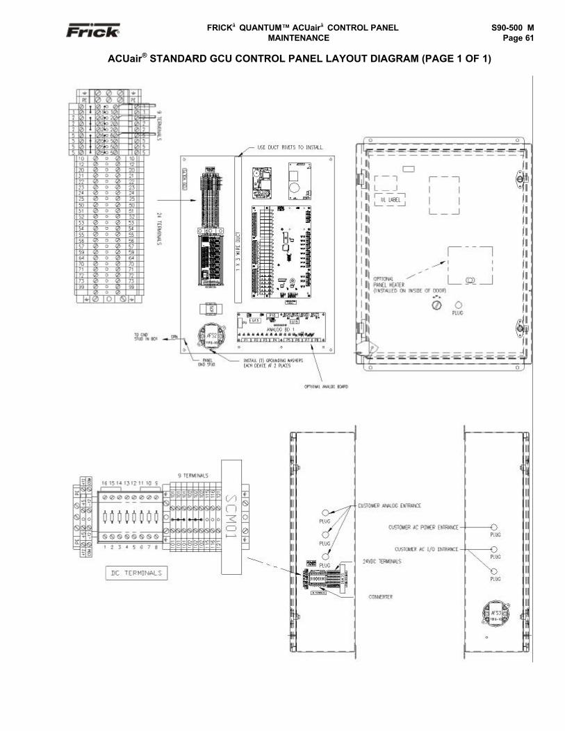
FRICK QUANTUM™ ACUair CONTROL PANEL S90-500 M MAINTENANCE Page 61
ACUair® STANDARD GCU CONTROL PANEL LAYOUT DIAGRAM (PAGE 1 OF 1)
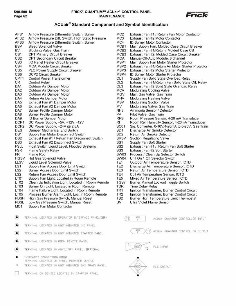
S90-500 M FRICK QUANTUM™ ACUair CONTROL PANELPage 62 MAINTENANCE
ACUair® Standard Component and Symbol Identification
AFS1 Airflow Pressure Differential Switch, Burner MC2 Exhaust Fan #1 / Return Fan Motor ContactorAFS2 Airflow Pressure Diff. Switch, High Static Pressure MC3 Exhaust Fan #2 Motor ContactorAFS3 Airflow Pressure Differential Switch, Burner MC4 ID Burner Motor ContactorBSV Bleed Solenoid Valve MCB1 Main Supply Fan, Molded Case Circuit BreakerBV Blocking Valve, Gas Train MCB2 Exhaust Fan #1/Return, Molded Case CBCB1 CPT Primary Circuit Breaker MCB3 Exhaust Fan #2, Molded Case Circuit BreakerCB2 CPT Secondary Circuit Breaker MOA Manual-Off-Auto Module, 8 channelCB3 I/O Panel Heater Circuit Breaker MSP1 Main Supply Fan Motor Starter ProtectorCB4 MOA Module Circuit Breaker MSP2 Exhaust Fan #1/Return Air Motor Starter ProtectorCB5 PLC Power Supply Circuit Breaker MSP3 Exhaust Fan #2 Motor Starter ProtectorCB6 DCP2 Circuit Breaker MSP4 ID Burner Motor Starter ProtectorCPT1 Control Power Transformer OL1 Supply Fan Solid State Overload RelayCR Control Relay OL2 Exhaust Fan #1/Return Fan Solid State O/L RelayDA1 Outdoor Air Damper Motor OL3 Exhaust Fan #2 Solid State Overload RelayDA2 Outdoor Air Damper Motor MCV Modulating Cooling ValveDA3 Outdoor Air Damper Motor MGV Main Gas Valve, Gas TrainDA4 Return Air Damper Motor MHV Modulating Heating ValveDA5 Exhaust Fan #1 Damper Motor MSV Modulating Suction ValveDA6 Exhaust Fan #2 Damper Motor MV Modulating Valve, Gas TrainDA7 Burner Profile Damper Motor NH3 Ammonia Sensor / DetectorDA8 Burner Profile Damper Motor PV Pilot Valve, Gas TrainDA9 ID Burner Damper Motor RPS Room Pressure Sensor, 4-20 mA TransducerDCP1 DC Power Supply, +5V, +12V, -12V RH Room Rel. Humidity Sensor, 4-20mA TransducerDCP2 DC Power Supply, +24V @ 2.8A SC01 Sig. Converter, 0-10V/4-20mA to 0-20V, Gas TrainDES Damper Mechanical End Switch SD1 Discharge Air Smoke DetectorDS1 Supply Fan Motor Disconnect Switch SD2 Return Air Smoke DetectorDS2 Exhaust Fan #1 / Return Fan Disconnect Switch SRSV Suction Regulating ValveDS3 Exhaust Fan #2 Disconnect Switch SS1 Supply Fan Soft StarterFSLL Float Switch Liquid Level, Flooded Systems SS2 Exhaust Fan #1 / Return Fan Soft StarterFSR Flame Safety Relay SS3 Exhaust Fan #2 Soft StarterFR Flame Rod SW03 Process / Clean Up Selector SwitchHGSV Hot Gas Solenoid Valve SW04 Unit On / Off Selector SwitchLLSV Liquid Level Solenoid Valve TE1 Outdoor Air Temperature Sensor, ICTDLS1 Supply Fan Access Door Limit Switch TE2 Discharge Air Temperature Sensor, ICTDLS2 Burner Access Door Limit Switch TE3 Return Air Temperature Sensor, ICTDLS2 Return Fan Access Door Limit Switch TE4 Coil Air Temperature Sensor, ICTDLT01 Supply Fan Light, Located in Room Remote TE5 Mixed Air Temperature Sensor, ICTDLT02 Clean Up Indication Light, Located in Room Remote TGS7 Burner Manual Lockout Toggle SwitchLT03 Burner On Light, Located in Room Remote TDR Time Delay RelayLT04 Flame Failure Light, Located in Room Remote TR1 Ignition Transformer, Burner Control CircuitLT05 Process Burner Alarm Light, Loc. in Room Remote TR2 Ignition Transformer, Burner Control CircuitPDSH High Gas Pressure Switch, Manual Reset TS2 Burner High Temperature Limit ThermostatPDSL Low Gas Pressure Switch, Manual Reset UV Ultra Violet Flame SensorMC1 Supply Fan Motor Contactor

FRICK QUANTUM™ ACUair CONTROL PANEL S90-500 M MAINTENANCE Page 63
COMMUNICATIONS WIRING DIAGRAMS
QUANTUM™ TO GCU COMMUNICATIONS
QUANTUM™ RS-422 COMMUNICATIONSTO CUSTOMER REMOTE COMPUTER/DCS
QUANTUM™ RS-485 COMMUNICATIONSTO CUSTOMER REMOTE COMPUTER/DCS
QUANTUM™ 3 RS-232 COMMUNICATIONSTO CUSTOMER REMOTE COMPUTER/DCS
QUANTUM™ 4 RS-232 COMMUNICATIONSTO CUSTOMER REMOTE COMPUTER/DCS
Com +
+ +
CLR
BLK
- Cable -Belden #9841
#24 AWGor Equal
+ Com
- Com
BLK
CLR
BLK
CLR
BLK
CLR
GCUPort 1 (J2)
Air Unit # 1
P2
P3
GCUPort 1 (J2)
Air Unit # 2
P2
P3
GCUPort 1 (J2)
Air Unit # 3
P2
P3
GCUPort 1 (J2)
Air Unit # 4
P2
P3
Com -
- -
GND GND
Terminals in theQuantum™ Control
Panel
GND
-RX / -TX
+RX / +RX
To CustomerRemote Computer /
DCS System
- Cable -Belden #9841
#24 AWG or EqualQUANTUM™ 3 OR 4
COM-2 (TB2)
Quantum™ Panel
1
2
3
4
BLK
CLR
-RX / -TX
+RX / +TX
-TX
+TXTo Customer
Remote Computer /DCS System
-RX
+RX
- Cable -Belden #9829
#24 AWG or EqualQUANTUM™ 3 OR 4
COM-2 (TB2)
Quantum™ Panel
1
2
3
4
BLK
GRN
BLK
RED
-RX
+RX
-TX
+TX
RXD
TXD
BLK
CLR
- Cable -Belden #9841
#24 AWG or Equal
To CustomerRemote Computer /
DCS System
Quantum™ Panel
RxD
TxD
QUANTUM™ 3COM-2 (P1)
1
3
5
7
9
2
4
6
8
10COM
COM
TX
RX
BLK
CLR
- Cable -Belden #9841
#24 AWG or EqualTo Customer
Remote Computer /DCS System
Quantum™ Panel
TXD
RXD
QUANTUM™ 4COM-2 (TB3)
COMCOM
1
2
3

S90-500 M FRICK QUANTUM™ ACUair CONTROL PANELPage 64 MAINTENANCE
RECOMMENDED SPARE PARTSPart Number Description Spare-1 Spare-2 Spare-3
Control Power333Q0001194 On/off power switch yes yes333Q0001195 On/off power switch contact block yes yes333Q9991418 Filter, Line111Q0280958 Surge suppresser yes yes yes
Displays (Refer to chart on page 26)640C0021G01 10.4"diag. LCD color VGA display assembly with backlight (Sharp) yes2
640C0052G01 10.4"diag. LCD color VGA display assembly with backlight (L.G.Philips) yes2
CCFT inverter (refer to the chart on page 26)Back light inverter cable (refer to the chart on page 26) yesDisplay cable (refer to the chart on page 26) yes
Harnesses640B0039H02 Condor DC power harness yes640B0049H01 Quantum™ DC Power Harness yes649B0862H01 Quantum™ 4 Adapter Harness yes640C0049H01 Wire Harness (for Dc Power Supply #GSC25A) yes640C0050H01 Wire Harness (for Dc Power Supply, #GLC65-24) yes640B0059H01 Wire Harness, AC Power (for GCU power supplies) yes
Power Supplies640C0022G01 DC power supply (for Quantum™ yes yes640B0060H01 Dc Power Supply, Condor #GSC25A (for GCU) yes yes640B0064H01 Dc Power Supply, Condor #GLC65-24 (for GCU) yes yes
GCU Board640D0117H01 GCU Board yes111Q0281061 Output Module 120/240 volt AC yes yes yes333Q0000116 Input Module 120 volt AC yes yes yes333Q0001326 Fuse, 5 amp, 250 V yes yes yes
Analog Board640C0026G01 Analog Broad yes
Keypads640D0060H01 Keypad/overlay Frick’s yes640B0031H01 Keypad cable yes
Misc.111Q0280889 Switch Differential Pressure, Dwyer #1910-00 yes333Q0001179 Heater, Flex, Watlow, 120vac, 150w yes640A0064H01 Resistor Module yes
Circuit Breakers649A0883H10 10 Amp circuit breaker yes649A0883H16 16 Amp circuit breaker yes649A0883H03 3 Amp Circuit Breaker yes
Quantum™ Controllers649C1091G02 Quantum™ 4 to Quantum™ 4 yes 1
649C1092G02 Upgrade from Quantum™ 3 to Quantum™ 4 yes1
Notes:• Note 1 – These processor boards are listed for reference. Each Quantum™ Control will have only one of these boards. Order
only the replacement board that is applicable to your controller, not both boards.• Note 2 – These displays are listed for reference. Each Quantum™ Control will have only one of these displays. Order only the
replacement display that is applicable to your controller.• Spare-1 - Normal spare parts kept on hand. Operation can wait more than 24 hours to receive replacement parts.
Plant typically has back-up units.• Spare-2 - Additional spare parts kept on hand. Operation must have parts in less than 24 hours. Plant does not have back-up
units. • Spare-3 - Critical operation. Plant must have continuous operation.
REMANUFACTURED PARTS Part Number Description
649A0985G21 GCU Board649A0985G31 Analog I/O Board649A0985G41 DC Power Supply (Condor to Condor)649A0985G51 Display Assembly (L.G. Philips to L.G. Philips)649A0985G61 Display Assembly (Sharp to Sharp)
FRICK QUANTUM™ ACUair CONTROL PANEL S90-500 M MAINTENANCE Page 65
INDEX
AAbout Screen ...............................................................22AC ...............................................................................10Active LED ...............................................................7, 10Allen-Bradley................................................................23Analog
Board ...................................................13, 20, 21, 22Description .....................................................20Settings ....................................................20, 21
Inputs....................................................................20Outputs .................................................................20
BBacklight ...................................................... 7, 10, 27, 62
Tube..................................................................7, 10Inverter..............................................................6, 27Voltage........................................................ 8, 11, 27
Booting ................................................................ 6, 7, 10
CCalibration.................................................... 7, 10, 21, 46Channel ......................................................13, 14, 20, 21Com-1..........................................................................11Com-2..........................................................................11Common ......................................................................13Communication
Board ................................................................8, 11Cable ....................................................................28Harness.................................................................13Protocol.................................................................23
Change Baud..................................................23Change Setpoints ...........................................23
Settings .................................................................21Status....................................................................13
Condor............................................................. 24, 26, 62Control
Panel.................................................................5, 28Power.................................................... 6, 15, 21, 27Signals............................................................13, 20Wiring....................................................................28
CPU board ........................................................... 6, 7, 10CT motor current ..........................................................21
DD.C. voltage ..................................................... 10, 13, 20D.C. Voltage / Communications Harness....... 9, 12, 16, 20Daisychain ...................................................................13Detect I/O Boards.........................................................23Digital
Board .............................................13, 14, 15, 19, 22Description ............................................................13I/O… ..................................................5, 7, 10, 13, 14Inputs..............................................................13, 14Multimeter ...............................................................5Outputs .................................................................14Volt Meter........................................................13, 24
Dipswitch ......................................................... 13, 20, 21Display........................................ 5, 6, 7, 8, 10, 11, 27, 62DVM.......................................................................13, 28
EEPROM........................................................................13Error message..........................................................7, 10
FFactory
Default .............................................................. 7, 10Setup .......................................................... 6, 29, 30
Failed communications .................................................13Faulty sensor ...............................................................21Flash Card .....................................................................6Fluorescent Tube ...........................................................6Frick®...........................................................................23Fuse .................................................................. 5, 14, 15Fuse Testing ................................................................14
GGND ............................................................................20Ground .........................................................5, 20, 21, 28Grounded........................................................... 5, 21, 28Grounding problem.......................................................21
HHot ..............................................................................15
II/O ..........................5, 7, 10, 13, 14, 20, 22, 24, 28, 49, 62
Board......................................... 7, 10, 13, 20, 22, 62Comm failure.........................................................22
Impedance...................................................................21O Factory Setup .............................................. 29, 30
Inductive loads .............................................................28Input ................................................. 5, 13, 14, 15, 20, 62Introduction....................................................................5Inverter .........................................................7, 10, 27, 62
JJumper .......................................................13, 20, 21, 27
Settings........................................................... 20, 27
KKeypad ........................................................................28
LLCD.................................................... 7, 8, 10, 11, 27, 62
Display.............................................................. 7, 10LED .................................................. 7, 10, 13, 14, 15, 22LG Philips .................................................7, 8, 10, 11, 27Logic Voltage ...............................................................13
MMain Board ....................................................................5Memory ..........................................................5, 7, 10, 29Modbus........................................................................23Motherboard ...................................................... 8, 11, 27Motor CT......................................................................20
NNEC..........................................................7, 8, 10, 11, 27Negative ......................................................................13Neutral.........................................................................15Noise ...........................................................................28
OOpen wire ....................................................................21Operating system .........................................................13Opto22.........................................................................28Output .........................................5, 13, 14, 15, 20, 21, 62
Modules ................................................................14
S90-500 M FRICK QUANTUM™ ACUair CONTROL PANELPage 66 MAINTENANCE
PPanel Setup ................................................23, 29, 31, 44PLC ............................................................................. 28Power ................. 5, 6, 7, 10, 13, 14, 15, 20, 24, 26, 28, 62
Supply .................................................13, 24, 26, 62Identification................................................... 24
Pressure transducers ............................................. 20, 28
QQuantum™ 1 ........................................................... 5, 62Quantum™ 2 .................................................................5Quantum™ 3 ..............................................5, 7, 8, 27, 62Quantum™ 4 ................................................5, 10, 11, 27
RRange.................................. 13, 20, 21, 22, 29, 30, 31, 44Receive (RX) ............................................................... 13Recommended Spare Parts.......................................... 62Return ......................................................................... 13RS-232 .............................................................. 8, 11, 28RS-422 .........................................................8, 11, 21, 28RS-485 .........................................................8, 11, 28, 61RX (receive)................................................................. 13
SSamsung .................................................. 7, 8, 10, 11, 27Screen ........................... 5, 6, 7, 10, 13, 14, 19, 21, 22, 23
Sensor..............................................................21, 22, 28Sensor fault ............................................................21, 22Service Screen .......................................................14, 19Setpoint Data Sheets ............................................... 6, 29Sharp ....................................................... 7, 8, 10, 11, 27Shorted wire ................................................................ 21Shutdown .................................................................... 22Signal .....................................................................20, 28Software................................ 7, 10, 13, 14, 20, 21, 28, 29Starter panel ................................................................ 28Static..............................................................5, 6, 15, 21
TTemperature probe ...................................................... 28Temperature transducers ............................................. 28Transducer ................................................... 5, 20, 21, 28Transmit (TX)............................................................... 13Troubleshooting.............................5, 7, 10, 14, 15, 20, 28TX (transmit)................................................................ 13TX/RX ..................................................................... 7, 10
VVideo cable.............................................................. 7, 10Voltage..............................................5, 13, 14, 15, 20, 27
WWiring problem ............................................................ 21

FRICK QUANTUM™ ACUair CONTROL PANEL S90-500 M MAINTENANCE Page 67

S90-500 M FRICK QUANTUM™ ACUair CONTROL PANELPage 68 MAINTENANCE
YORK Refrigeration100 CV Avenue, P.O. Box 997 Waynesboro, Pennsylvania USA 17268-0997Phone: 717-762-2121 • Fax: 717-762-8624 • www.frickcold.com
Subject To Change Without NoticePrinted in U.S.A.