frigg field cessation plan · frigg field cessation plan close out report dm#946614 page 2 of 62 12...
TRANSCRIPT
Frigg Field Cessation PlanClose Out Report

Frigg Field Cessation Plan Close Out Report
DM#946614 Page 2 of 62 12 May 2011
This page intentionally left blank

Frigg Field Cessation Plan Close Out Report
DM#946614 Page 3 of 62 12 May 2011
Frigg Field Cessation Plan
Close Out Report
Stavanger 12 May 2011
TOTAL E&P NORGE AS TOTAL E&P UK Ltd. Statoil Petroleum AS
TOTAL E&P NORGE AS, PO Box 168, 4001 Stavanger, Norway

Frigg Field Cessation Plan Close Out Report
DM#946614 Page 4 of 62 12 May 2011
This page intentionally left blank

Frigg Field Cessation Plan Close Out Report
DM#946614 Page 5 of 62 12 May 2011
Foreword This report represents the Close-Out Report for the decommissioning of the Frigg Field as requested in the following letters from the Norwegian and UK authorities stating that a report shall be submitted within four months after the completion of the work: • Letter dated 01.10.2003 from the Norwegian Ministry of Petroleum and Energy to TOTAL
E&P NORGE AS: “Disponering av innretningene på Frigg-feltet”; (“Disposal of the installations on the Frigg Field” (excluding the disposal of the concrete substructure TCP2)) [2].
• Letter dated 18.11 2003 from the UK Department of Trade and Industry to TOTAL E&P
NORGE AS: "Petroleum Act 1998 Abandonment of the Frigg Field Facilities", incl. "Petroleum Act 1998 Section 32(1) Approval of a programme for Abandonment" and "Permit to leave in place the concrete substructures of the Frigg TP1 and CDP1 installations in accordance with OSPAR decision 98/3" [3].
• Letter dated 23.04.2004 from the Norwegian Ministry of Petroleum and Energy to TOTAL
E&P NORGE AS: "Tillatelse til etterlatelse av betongunderstellet TCP2 på Frigg-feltet"; (“Approval to leave in place the concrete substructure TCP2”) [4].
The completion of the decommissioning work, as defined in the approved Frigg Field Cessation Plan [1], the letters of approval [2], [3] & [4] and the OSPAR consultation document [5], was considered completed when the SFF Services Limited in a letter dated 19th January 2011 confirmed that the trawl test within the 500m zone of the Frigg Field had been performed successfully.

Frigg Field Cessation Plan Close Out Report
DM#946614 Page 6 of 62 12 May 2011
This page intentionally left blank
Frigg Field Cessation Plan Close Out Report
DM#946614 Page 7 of 62 12 May 2011
LIST OF CONTENTS
FOREWORD 5
1 INTRODUCTION 9
2 SUMMARY 10
3 APPROVED DISPOSAL ARRANGEMENTS 11
3.1 Approval of the Frigg Field Cessation Plan 11
3.2 Leaving in Place the Concrete Substructures 12
4 ORGANISATION OF THE WORK 13
5 REMOVAL OF THE NORWEGIAN FACILITIES 15
5.1 DP2 Platform 15 5.1.1 DP2 Topsides 15 5.1.2 DP2 Jacket 16 5.1.3 Gravel placement in the dredged areas at DP2 17 5.1.4 Drill Cuttings 17
5.2 DP1 Jacket 19 5.2.1 DP1 Jacket 19 5.2.2 Gravel placement in the dredged areas at DP1 20
5.3 TCP2 Platform 21 5.3.1 TCP2 Topsides 21 5.3.2 Removal of TCP2 External Steelwork 23
5.4 Removal of Pipelines and Cables in Norwegian Sector 24 5.4.1 In-field pipelines and cables between Frigg Platforms 24 5.4.2 Removal of Inter-field Pipelines and Cables 25 5.4.3 32” Frigg Spur from TCP2 25
6 REMOVAL OF THE UK FACILITIES 26
6.1 QP Platform 26 6.1.1 QP Topsides 26 6.1.2 QP Jacket 26 6.1.3 Gravel placement in the dredged areas at QP 27
6.2 TP1 Platform 28 6.2.1 TP1 Topsides 28 6.2.2 TP1 External Steelwork 29
6.3 CDP1 Platform 31 6.3.1 CDP1 Topsides 31
6.4 Removal of Pipelines and Cables in the UK Sector 33 6.4.1 In-field pipelines and cables between Frigg Platforms 33 6.4.2 Removal of Alwyn Disused Pipeline Section 34 6.4.3 24” and 32” Disused Pipeline Sections to/from TP1 34
7 ONSHORE DISPOSAL 35
7.1 Demolition and Final Disposal 35
7.2 Hazardous Waste 37
7.3 Transfrontier Shipment of Waste 38

Frigg Field Cessation Plan Close Out Report
DM#946614 Page 8 of 62 12 May 2011
8 SAFETY PERFORMANCE 39
8.1 Safety 39
8.2 Safety Initiatives 39 8.2.1 Hot Cutting on Painted Surfaces 40 8.2.2 Risks during Offshore Decommissioning 40
9 ENVIRONMENTAL PERFORMANCE 41
9.1 Recycling Rates 41
9.2 Comparison with the Assumptions in the EIA 42
9.3 Reuse of equipment 43
10 GENERAL VISUAL INSPECTION OF THE CONCRETE SUBSTRUCTURES 44
10.1 Below-Water Inspection 44
10.2 Above-Water Inspection 44
10.3 Future monitoring 44
11 DEBRIS CLEARANCE 45
11.1 Debris Clearance June 2008 45
11.2 Debris Clearance February 2010 45
12 ENVIRONMENTAL SURVEYS 46
13 TRAWL TESTS 48
13.1 Trawl test in September 2008 48
13.2 Trawl test in September 2010 49
14 MARKING OF THE CONCRETE SUBSTRUCTURES 50
14.1 Aid to Navigation (AtoN) 50
14.2 Information to Mariners 51
14.3 FishSafe 51
15 RECOMMENDED MITIGATING MEASURES IN THE EIA 52
16 PROJECT SCHEDULE 54
17 COST SUMMARY 56
17.1 Cost for Removal and Disposal of the Norwegian Facilities 56
17.2 Cost for Removal and Disposal of the UK Facilities 56
18 INDEPENDENT VERIFICATION 58
19 FEEDBACK ON STRUCTURAL PERFORMANCE 59
20 REFERENCES 60
APPENDIX 1 61
Clear Seabed Certificates 61
Frigg Field Cessation Plan Close Out Report
DM#946614 Page 9 of 62 12 May 2011
1 Introduction The objective of this Close-out Report is to report on the completion of the decommissioning of the Frigg Field facilities operated by TOTAL E&P NORGE AS (TOTAL Norge) as defined in the approved Frigg Field Cessation Plan. The terms of reference for this Close-Out Report are as follows: 1. The Frigg Field Cessation Plan, dated 9 May 2003 [1], approved by:
the Norwegian Ministry of Petroleum and Energy (MPE) for the Norwegian facilities on the Frigg Field in letters dated 1 October 2003 [2] and 23 April 2004 [4], and
the UK Department of Trade and Industry (DTI) (today the Department of Energy and
Climate Change (DECC)) for the UK facilities on the Frigg Field in a letter dated 18 November 2003 [3].
2. Terms of the Permit Conditions issued by the MPE for TCP2 [4] and the DTI for CDP1 and
TP1 [3] for leaving in place the concrete substructures at their present location. 3. The report “An Assessment of Proposals for the Disposal of the Concrete Substructures of
Disused Frigg Field Installations TCP2, CDP1 and TP1”, dated 6 August 2002 [5], which was submitted to the OSPAR Contracting Parties for consultation on 20 September 2002.
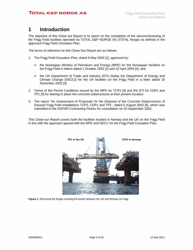
This Close-our Report covers both the facilities located in Norway and the UK on the Frigg Field in line with the approach agreed with the MPE and DECC for the Frigg Field Cessation Plan. Figure 1. Removing the bridge crossing the border between the UK and Norway on Frigg
TP1 in the UK TCP2 in Norway

Frigg Field Cessation Plan Close Out Report
DM#946614 Page 10 of 62 12 May 2011
2 Summary After more than 27 years in operation, the gas production from the Frigg reservoir was finally shut-in on 26 October 2004 (TP1 started in 1977 and TCP2 in 1978). The Frigg Field had by then delivered about 192 billion standard cubic metres of gas to the UK domestic market. The first removal operations offshore started in early 2005 after the facilities were made safe and cold. The final offshore lifts took place in 2009, followed by post-removal activities within the 500m zone during 2010. The removal of the Frigg facilities is the largest offshore decommissioning project executed so far in the North Sea. A number of new technologies were introduced with the aim to minimise the risk to personnel and enhance efficiency; as described in the Sections 5.1.2, 5.3.1, 8.2 and 14.1. Considering the complexity of the decommissioning work it can be concluded that all the proactive safety efforts have paid off with an overall good safety performance. About 73,000 tonnes of material have been brought to shore for final disposal in which 98% of the material has been recycled. Strict procedures were introduced to control the handling and disposal of hazardous materials weighing about 1,620 tonnes. The removal of external steel attached to the concrete substructures has been done as far as practicably possible with a few items left after significant difficulties in attempting a removal. These cases have been agreed with the authorities. The final cost shows an increase of 12.6% compared to the project budget established in 2004. The completion of the approved decommissioning work was considered completed when the SFF Services Limited in a letter dated 19th January 2011 confirmed that the trawl test within the 500m zone of the Frigg Field had been performed successfully. This is two years ahead of the commitment made in the Cessation Plan stating that all works should be completed by the end of 2012. DNV’s independent verification concluded that 48 out of 50 requirements for leaving the concrete substructures in place were met. Minor discrepancies on two requirements were identified related to the inside cleaning of equipment inside the concrete columns of TCP2 and TP1. Tanks and pipes were drained but not flushed in accordance to the procedures. The volume of chemicals or oil left inside each concrete substructure has been estimated to about 3 litres by TOTAL Norge. Both discrepancies have been assessed by DNV to have insignificant impact on the environment and the leave in place condition.
Figure 2. Frigg Field before removal commenced
Figure 3. Frigg Field after offshore removal works
TCP2
CDP1
TP1

Frigg Field Cessation Plan Close Out Report
DM#946614 Page 11 of 62 12 May 2011
3 Approved Disposal Arrangements
3.1 Approval of the Frigg Field Cessation Plan The Norwegian MPE approved the recommended arrangements for the facilities located in the Norwegian sector while the UK DECC1
gave similar approval for the facilities placed on the UK sector of Frigg.
Tables 1 and 2 summarise the approved disposal arrangements for the facilities on the Frigg Field which were in line with the recommendations from the Frigg Field Licensees.
Norwegian Facilities Approved disposal arrangements by the Norwegian Ministry of Petroleum and Energy
Steel Platform Topsides DP2 Removal and onshore disposal
Steel Platform Substructures DP2 and DP1 Removal and onshore disposal
Concrete Platform Topsides TCP2 Removal and onshore disposal
Concrete Platform Substructures TCP2 Leave in place, removing as much external steelwork as reasonably practicable
Infield Pipelines and Cables Between TCP2 & DP2 Removal and onshore disposal
Drill Cuttings DP2 Leave in place
Table 1. Approved disposal arrangements for the Norwegian facilities on Frigg Field
UK Facilities Approved disposal arrangements by the UK Department of Energy and Climate Change
Steel Platform Topsides QP Removal and onshore disposal
Steel Platform Substructures QP Removal and onshore disposal
Concrete Platform Topsides TP1 & CDP1 Removal and onshore disposal
Concrete Platform Substructures TP1 & CDP1 Leave in place, removing as much external steelwork as reasonably practicable
Infield Pipelines and Cables Between CDP1&TP1/QP, TP1 & FP Removal and onshore disposal
Drill Cuttings CDP1 Leave in place
Table 2. Approved disposal arrangements for the UK facilities on Frigg Field
1 DECC – The UK Department of Energy and Climate Change was named the Department of Trade and Industry (DTI) when the Frigg Field Cessation Plan was approved.
Frigg Field Cessation Plan Close Out Report
DM#946614 Page 12 of 62 12 May 2011
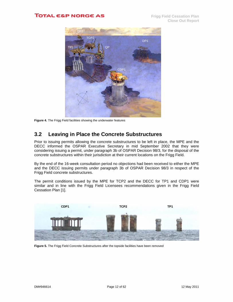
TCP2 Figure 4. The Frigg Field facilities showing the underwater features
3.2 Leaving in Place the Concrete Substructures Prior to issuing permits allowing the concrete substructures to be left in place, the MPE and the DECC informed the OSPAR Executive Secretary in mid September 2002 that they were considering issuing a permit, under paragraph 3b of OSPAR Decision 98/3, for the disposal of the concrete substructures within their jurisdiction at their current locations on the Frigg Field. By the end of the 16-week consultation period no objections had been received to either the MPE and the DECC issuing permits under paragraph 3b of OSPAR Decision 98/3 in respect of the Frigg Field concrete substructures. The permit conditions issued by the MPE for TCP2 and the DECC for TP1 and CDP1 were similar and in line with the Frigg Field Licensees recommendations given in the Frigg Field Cessation Plan [1].
Figure 5. The Frigg Field Concrete Substructures after the topside facilities have been removed
TCP2
CDP1
DP2
TP1
QP
DP1
CDP1 TCP2 TP1
Frigg Field Cessation Plan Close Out Report
DM#946614 Page 13 of 62 12 May 2011
CDP1
DP1 QP
DP2
TCP2
TP1 4 Organisation of the Work The decommissioning of the Frigg Field was organised as a project with a Project Director reporting the Managing Director of TOTAL Norge. Key personnel were recruited from previous decommissioning projects for the Frigg satellite fields: North East Frigg, East Frigg, Lille-Frigg and Frøy. The experience from these removal projects was in many respects the reference when establishing the project organisation. The Operational Department was deeply involved in making the Frigg facilities hydrocarbon free after the wells on DP2 were plugged and abandoned (the wells on CDP1 were plugged and abandoned in 1990). This work was done by the maintenance contractor involved in the tail end production as they had first hand knowledge about the production and utility systems. It included also the passivation of the electrical and instrumentation systems that were not required during the removal works. Prior to the award of the main removal contract some decommissioning works on the topside facilities were initiated which would not interfere with the removal contractors plans. The main purpose for this initiative was to avoid a cold phase period between the shut-in of the production and the offshore start up of the main removal contract. The main contractors and subcontractors involved in the decommissioning of the Frigg Field facilities are shown on Figure 6. • Aker Kværner Offshore Partner, Stavanger - Norway, was awarded in October 2004 the
contract for the offshore removal and onshore disposal of the five topsides and three jackets in a lump sum contract involving Engineering, Preparation, Removal and Disposal (EPRD Contract). Works related to hazardous waste were based on a daily rate. Their main subcontractors were Saipem UK, Aker Marine Contractors, Aker Stord and Shetland Decommissioning Company being responsible for the activities shown in Figure 6.
• DeepOcean, Haugesund, - Norway, received the contract for removal and onshore disposal
of the external steel works on the concrete substructures TCP2 and TP1. • Sonsub Ltd, London – UK, was awarded the contract for removal and disposal of the infield
pipelines and cables. In 2003 the offshore removal and onshore disposal of the topside facilities on the concrete platform MCP-01, operated by TOTAL E&P UK in Aberdeen, was incorporated into the Frigg Cessation Project. The project was then renamed to the Frigg & MCP-01 Cessation Project. This work was incorporated in the contract awarded to Aker Kværner Offshore Partner in 2004. The completion of this work is reported in the Close-Out Report issued by TOTAL E&P UK for the decommissioning of MCP-01 in line with the approved MCP-01 Decommissioning Programme dated 11 September 2007.

Frigg Field Cessation Plan Close Out Report
DM#946614 Page 14 of 62 12 May 2011
Figure 6. Overview of main contractors and subcontractors engaged in the decommissioning of the Frigg Field facilities
Frigg Field Cessation Plan Close Out Report
DM#946614 Page 15 of 62 12 May 2011
5 Removal of the Norwegian Facilities
5.1 DP2 Platform Table 3 summarises the overall weight of the removed DP2 platform.
DP2 Platform Weight removed (tonne) Topsides 4 002 Jacket+MSF+grout+piles 11 122 Sum 15 124
Table 3. Weight of the platform DP2
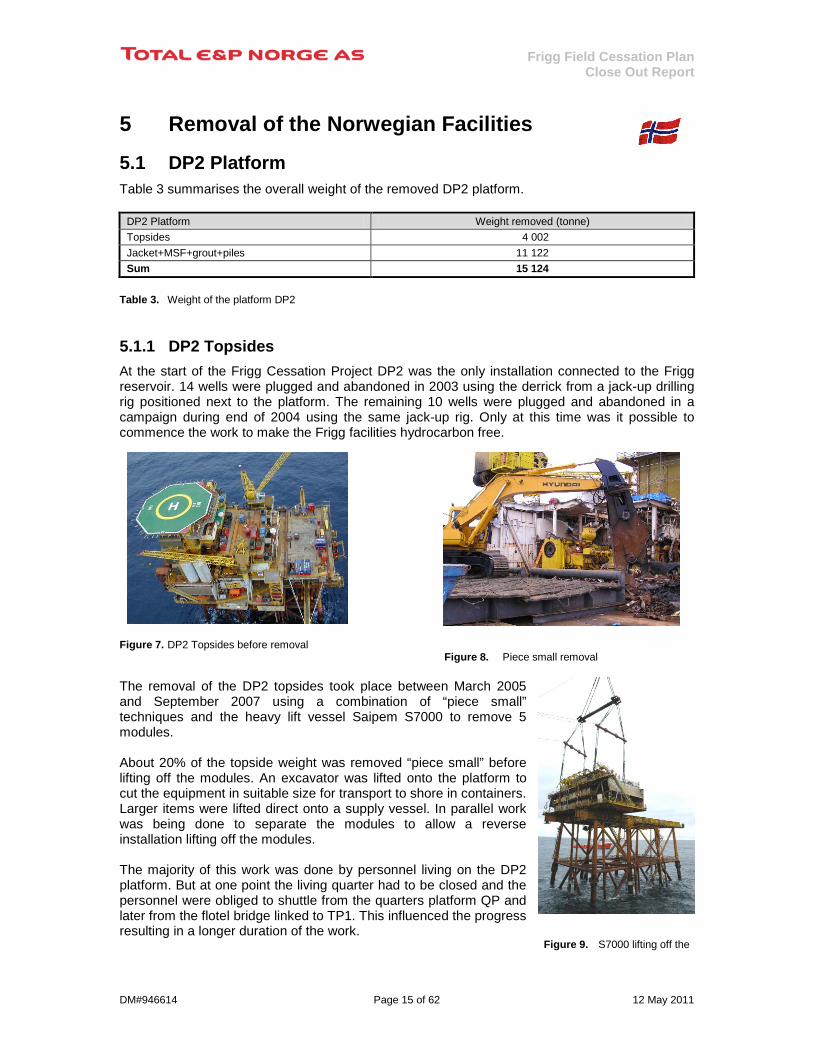
5.1.1 DP2 Topsides At the start of the Frigg Cessation Project DP2 was the only installation connected to the Frigg reservoir. 14 wells were plugged and abandoned in 2003 using the derrick from a jack-up drilling rig positioned next to the platform. The remaining 10 wells were plugged and abandoned in a campaign during end of 2004 using the same jack-up rig. Only at this time was it possible to commence the work to make the Frigg facilities hydrocarbon free.
Figure 7. DP2 Topsides before removal Figure 8. Piece small removal
The removal of the DP2 topsides took place between March 2005 and September 2007 using a combination of “piece small” techniques and the heavy lift vessel Saipem S7000 to remove 5 modules. About 20% of the topside weight was removed “piece small” before lifting off the modules. An excavator was lifted onto the platform to cut the equipment in suitable size for transport to shore in containers. Larger items were lifted direct onto a supply vessel. In parallel work was being done to separate the modules to allow a reverse installation lifting off the modules. The majority of this work was done by personnel living on the DP2 platform. But at one point the living quarter had to be closed and the personnel were obliged to shuttle from the quarters platform QP and later from the flotel bridge linked to TP1. This influenced the progress resulting in a longer duration of the work.
Figure 9. S7000 lifting off the
Frigg Field Cessation Plan Close Out Report
DM#946614 Page 16 of 62 12 May 2011
last of DP2 modules The heavy lift vessel S7000 removed the modules from the DP2 support frame in one campaign. The modules were lifted onto S7000’s own deck and transported to the onshore disposal yard at Stord in Norway
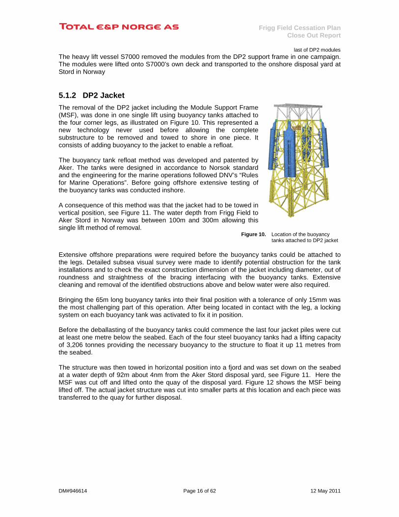
5.1.2 DP2 Jacket The removal of the DP2 jacket including the Module Support Frame (MSF), was done in one single lift using buoyancy tanks attached to the four corner legs, as illustrated on Figure 10. This represented a new technology never used before allowing the complete substructure to be removed and towed to shore in one piece. It consists of adding buoyancy to the jacket to enable a refloat. The buoyancy tank refloat method was developed and patented by Aker. The tanks were designed in accordance to Norsok standard and the engineering for the marine operations followed DNV’s “Rules for Marine Operations”. Before going offshore extensive testing of the buoyancy tanks was conducted inshore. A consequence of this method was that the jacket had to be towed in vertical position, see Figure 11. The water depth from Frigg Field to Aker Stord in Norway was between 100m and 300m allowing this single lift method of removal.
Figure 10. Location of the buoyancy tanks attached to DP2 jacket
Extensive offshore preparations were required before the buoyancy tanks could be attached to the legs. Detailed subsea visual survey were made to identify potential obstruction for the tank installations and to check the exact construction dimension of the jacket including diameter, out of roundness and straightness of the bracing interfacing with the buoyancy tanks. Extensive cleaning and removal of the identified obstructions above and below water were also required. Bringing the 65m long buoyancy tanks into their final position with a tolerance of only 15mm was the most challenging part of this operation. After being located in contact with the leg, a locking system on each buoyancy tank was activated to fix it in position. Before the deballasting of the buoyancy tanks could commence the last four jacket piles were cut at least one metre below the seabed. Each of the four steel buoyancy tanks had a lifting capacity of 3,206 tonnes providing the necessary buoyancy to the structure to float it up 11 metres from the seabed. The structure was then towed in horizontal position into a fjord and was set down on the seabed at a water depth of 92m about 4nm from the Aker Stord disposal yard, see Figure 11. Here the MSF was cut off and lifted onto the quay of the disposal yard. Figure 12 shows the MSF being lifted off. The actual jacket structure was cut into smaller parts at this location and each piece was transferred to the quay for further disposal.

Frigg Field Cessation Plan Close Out Report
DM#946614 Page 17 of 62 12 May 2011
Figure 11. DP2 Jacket and MSF tow arriving the inshore location
Figure 12. DP2 MSF being lifted off
5.1.3 Gravel placement in the dredged areas at DP2 A dredged excavation three metres deep was required around each pile cluster to allow a ROV to cut the steel jacket piles a minimum of one metre below the seabed, as illustrated in Figure 13. On Figure 14 the foot print after the jacket has been removed is shown in a multi beam echo sounder picture. The Environmental Impact Assessment in the Frigg Field Cessation Plan [1] defined the need to cover the remaining jacket piles in the dredged areas and as they could represent a potential obstruction to future bottom trawl fishing. Consequently, gravel has been placed where the seabed have been dredged to facilitate the cutting of the jacket piles, see illustration on Figure 13. The seabed profiles after the removal of the two 26” pipelines from DP2 to TCP2 are also clearly visible on the lower part on Figure 14. Figure 13. Seabed profile after piles were cut
Figure 14. Foot prints of DP2 Jacket and pipelines after removal
5.1.4 Drill Cuttings The amount of drill cuttings at DP2 has been estimated to be about 400m3 with a maximum thickness of 20cm contained within an area of 80m x 120m around the platform. The cuttings are significantly less contaminated than other cuttings deposits in the North Sea. The reasons for this are that the wells are drilled mainly with water based mud, the cuttings have been very finely grained, and that the cuttings have been partially mixed with and covered by natural sedimentation.

Frigg Field Cessation Plan Close Out Report
DM#946614 Page 18 of 62 12 May 2011
During the cutting operations of the piles at minimum one metre below the seabed some disturbance of the drill cuttings near the four corner legs took place. This issue was also identified in the Environmental Impact Assessment (EIA) which stated: ”Since the DP2 steel substructure will have to be removed, some of the cuttings layer may be further mixed with natural sediments during the removal operations. The environmental effects from removing/mixing the cuttings material at the field is considered small. In the long term, the seabed at the field will be left in a better condition than at present” [1].

Frigg Field Cessation Plan Close Out Report
DM#946614 Page 19 of 62 12 May 2011
5.2 DP1 Jacket Table 4 summarises the overall weight of the removed DP1 jacket.
DP1 Jacket Weight removed (tonne) Jacket 7 364
Table 4. Weight of the DP1 jacket
5.2.1 DP1 Jacket DP1 was the first installation to arrive on the Frigg Field in 1974. During the launch operation, however, the ballast tanks providing buoyancy to the steel jacket collapsed, resulting in loss of control and the structure hit the seabed. The structural damage was so severe that repair or reuse was not possible. During the Cessation Project lifting the damaged steel jacket in one piece was therefore not an option owing to the uncertainties about its structural integrity. Instead, the jacket was cut into stable and liftable sections.
Figure 15. Work platform on DP1 jacket To overcome the challenge of working in the splash zone for the preparation of the lifting of the top section of the damaged jacket, a work platform and spreader frame was installed as shown in Figure 15. The system functioned very efficiently and contributed to a safe operation within the set weather criteria. Personnel could access the tops of the jacket legs to remove the cap plates and install the internal lift tools. The top section, representing about one-third of the jacket, was removed in one lift by S7000, see Figure 16.
Figure 16. Upper part of DP1 jacket lifted off by S7000
The middle section was cut into smaller sections using a ROV deployed from a construction vessel. The cut sections were placed in large baskets on the seabed, which were later removed by S7000. After some preparations from a smaller construction vessel the bottom section of the jacket was removed by S7000 in two parts, see Figure 17. Considerable amount of debris was removed after the damaged DP jacket had been removed.
Figure 17. A bottom section on the deck of S7000

Frigg Field Cessation Plan Close Out Report
DM#946614 Page 20 of 62 12 May 2011
5.2.2 Gravel placement in the dredged areas at DP1 Even though DP1 was not piled to the seabed certain dredging around the legs was required as the jacket had settled into the seabed over the past 34 years. However, the dredging was less extensive than at the DP2 and QP platforms where it was required to cut the piles at least one metre below the seabed. Figure 18 shows the foot prints of the DP1 jacket after the jacket had been removed but before the removal of the debris. These footprints have been filled with gravel in line with the recommendation given in the EIA [1]. Figure 18. Foot print of DP1 Jacket after removal showing the debris which have been removed
Frigg Field Cessation Plan Close Out Report
DM#946614 Page 21 of 62 12 May 2011
5.3 TCP2 Platform Table 5 summarises the overall weight removed from the concrete platform TCP2.
TCP2 Platform Weight removed (tonne) Topsides incl. MSF 21 433 External steelwork 739 Sum 22 172
Table 5. Weight of the material removed from TCP2 platform
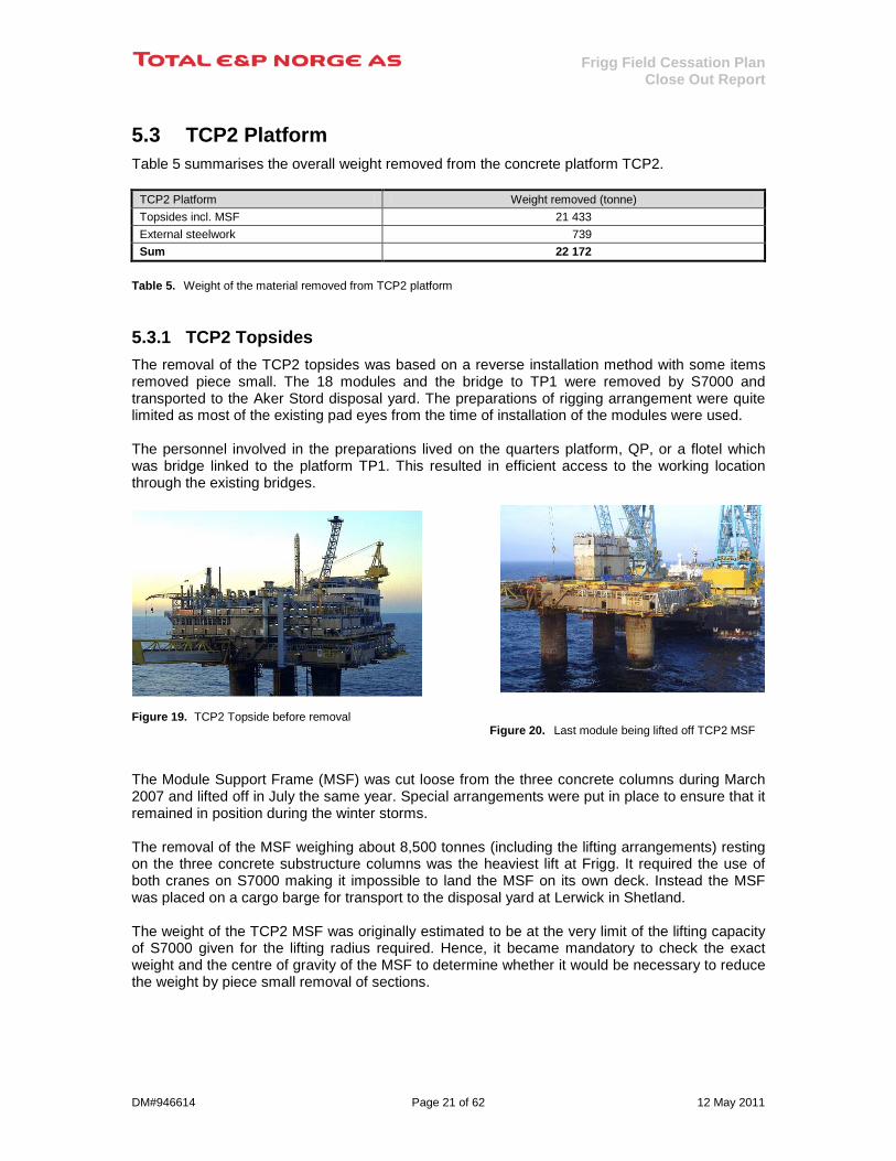
5.3.1 TCP2 Topsides The removal of the TCP2 topsides was based on a reverse installation method with some items removed piece small. The 18 modules and the bridge to TP1 were removed by S7000 and transported to the Aker Stord disposal yard. The preparations of rigging arrangement were quite limited as most of the existing pad eyes from the time of installation of the modules were used. The personnel involved in the preparations lived on the quarters platform, QP, or a flotel which was bridge linked to the platform TP1. This resulted in efficient access to the working location through the existing bridges.
Figure 19. TCP2 Topside before removal Figure 20. Last module being lifted off TCP2 MSF
The Module Support Frame (MSF) was cut loose from the three concrete columns during March 2007 and lifted off in July the same year. Special arrangements were put in place to ensure that it remained in position during the winter storms. The removal of the MSF weighing about 8,500 tonnes (including the lifting arrangements) resting on the three concrete substructure columns was the heaviest lift at Frigg. It required the use of both cranes on S7000 making it impossible to land the MSF on its own deck. Instead the MSF was placed on a cargo barge for transport to the disposal yard at Lerwick in Shetland. The weight of the TCP2 MSF was originally estimated to be at the very limit of the lifting capacity of S7000 given for the lifting radius required. Hence, it became mandatory to check the exact weight and the centre of gravity of the MSF to determine whether it would be necessary to reduce the weight by piece small removal of sections.

Frigg Field Cessation Plan Close Out Report
DM#946614 Page 22 of 62 12 May 2011
Conventional weighing system could not be used due to the very limited space between the MSF and the three concrete columns after being cut free with diamond wire. A weighing system using flat jacks was therefore developed (Patented by IWS AS), see Figure 21, and certified by the DNV. It required simple preparations but delivered the weighing accuracy needed.
Figure 21. The Flat Jack Weighing system To avoid extensive and complex welding for sea fastening on the cargo barge, a new technology called the “flexi sea fastening system” was developed, see Figure 22. This system made almost personnel intervention on the barge unnecessary. Rubber elements were glued to the barge grillage, and steel gripper plates were welded underneath the MSF. When the MSF was landed on the barge, see Figure 23, the gripper plates bit into the rubber and allowed the transfer of both vertical and horizontal loads. This connection was strong enough to provide a safe sea fastening for transport to the disposal yard at Lerwick in Shetland.
Figure 22. Illustration of the flexi sea fastening system
Figure 23. S7000 lifting TCP2 MSF in a single lift

Frigg Field Cessation Plan Close Out Report
DM#946614 Page 23 of 62 12 May 2011
5.3.2 Removal of TCP2 External Steelwork The principle established in the approved Cessation Plan was that any external steelwork attached to the concrete substructure representing a future potential obstacle for bottom trawl fishing near the platform should be removed as far as reasonably practicable. The external steelwork attached to the TCP2 concrete structure was mainly: • External risers entering the concrete columns at the top of the
caisson • Utility risers from the topsides • External ladders and platforms (used for emergency evacuation) • Vent pipes with supports (used during the installation) • Various sheave assemblies, roller guides and blocks
Figure 24. External steelwork on TCP2 Concrete Substructure
Abseilers were used extensively to remove the items above water. Below water, the steelwork was cut using various underwater cutting tools attached to a ROV operated from the platform deck. All the steel was brought to the deck and placed in containers and transported to the onshore disposal facility where all was recycled. All the identified steelwork above and below water has been removed except for three items. The 5.8 tonne pull-in sheave located on concrete base slab next to the seabed turned out to be impossible to remove despite applying a force of 50 tonnes after all the bolts were cut. As this item would not represent any obstructions to fishing, MPE has agreed to TOTAL Norge’s recommendation to leave it in place. The other two items are pipeline protection frames for the two 26” pipelines from DP2 at the entrance point on the TCP2 concrete slab. Attempts to remove these items turned out to practically difficult. They extend about five metres from the concrete slab and up to four metres from the seabed. Both the Scottish Fishermen’s Federation and the Norwegian Fishermen’s Federation (Norges Fiskarlag) have been informed in meetings without expressing any objections. The MPE has been informed in a letter without making any objections. It can be concluded the target set to remove all external steelwork attached to the TCP2 concrete substructure, as far as reasonably practicable, has been achieved.
Figure 25. Before and after the removal of utility risers and ladders on one of the TCP2 concrete columns.

Frigg Field Cessation Plan Close Out Report
DM#946614 Page 24 of 62 12 May 2011
5.4 Removal of Pipelines and Cables in Norwegian Sector
5.4.1 In-field pipelines and cables between Frigg Platforms Table 6 shows the lengths of pipelines and cables removed between the Norwegian installations on the Frigg Field. The overall weight of the pipelines and cables recovered within the 500m zone on Frigg (Norwegian and UK sector) was about 5,328 tonnes.
Pipeline No. Pipeline/Cable From To Removed Rigid pipe (metre) Flexible pipe (metre) Cable (metre)
R2 26” Gas line DP2 TCP2 528.9 R3 26” Gas line DP2 TCP2 608.8 J1 4” Methanol line DP2 TCP2 736.5 142.0 J2 8” Mud/Nitrogen line DP2 TCP2 523.4 3” Electrical cable DP2 TCP2 884.0 15/8” Telecom Cable DP2 TCP2 922.0
Table 6. Removed pipelines and cables between the Norwegian installations on Frigg Figure 26. Overview of the pipelines and cables between the Norwegian installations on Frigg Pipelines/Cables All the pipelines and cables between the Norwegian installations DP2 and TCP2 have been removed and taken to shore for disposal. Concrete saddles/blocks 18 concrete blocks have been recovered next to DP2 which is six more that quoted in the Cessation Plan. Mattresses Within the 500m zone of the Frigg installations 160 concrete mattresses have been removed by the contractor removing the pipelines and cables.
Figure 27. Concrete mattresses removed
2x26” pipelinespartly covered by sand
4” pipeline
3” & 15/8” cables
8” pipeline
DP2TCP2
2x26” pipelinespartly covered by sand
4” pipeline
3” & 15/8” cables
8” pipeline
DP2TCP2
Frigg Field Cessation Plan Close Out Report
DM#946614 Page 25 of 62 12 May 2011
Bags A considerable number of sand bags protecting the flexible line J4 have been removed. Some bags were impossible to remove as they disintegrated when attempts were made to move them. The Multi Beam Echo Sounder performed after the removal campaign identified no concrete saddles/blocks or mattresses left. This is supported by the fact that the two trawl sweeps in the area in question was successful. Reference is also made to Section 11 addressing the debris clearance campaigns during and after the offshore removal works were completed.
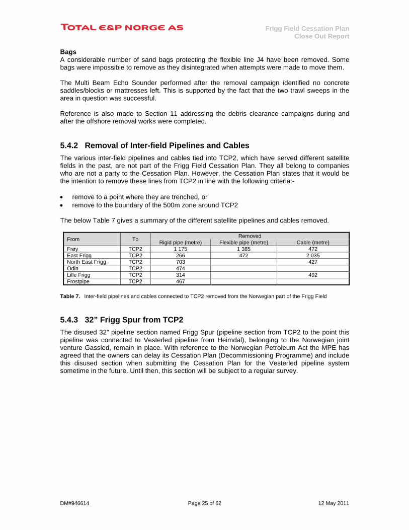
5.4.2 Removal of Inter-field Pipelines and Cables The various inter-field pipelines and cables tied into TCP2, which have served different satellite fields in the past, are not part of the Frigg Field Cessation Plan. They all belong to companies who are not a party to the Cessation Plan. However, the Cessation Plan states that it would be the intention to remove these lines from TCP2 in line with the following criteria:- • remove to a point where they are trenched, or • remove to the boundary of the 500m zone around TCP2 The below Table 7 gives a summary of the different satellite pipelines and cables removed.
From To Removed Rigid pipe (metre) Flexible pipe (metre) Cable (metre)
Frøy TCP2 1 175 1 385 472 East Frigg TCP2 266 472 2 035 North East Frigg TCP2 703 427 Odin TCP2 474 Lille Frigg TCP2 314 492 Frostpipe TCP2 467
Table 7. Inter-field pipelines and cables connected to TCP2 removed from the Norwegian part of the Frigg Field
5.4.3 32” Frigg Spur from TCP2 The disused 32” pipeline section named Frigg Spur (pipeline section from TCP2 to the point this pipeline was connected to Vesterled pipeline from Heimdal), belonging to the Norwegian joint venture Gassled, remain in place. With reference to the Norwegian Petroleum Act the MPE has agreed that the owners can delay its Cessation Plan (Decommissioning Programme) and include this disused section when submitting the Cessation Plan for the Vesterled pipeline system sometime in the future. Until then, this section will be subject to a regular survey.

Frigg Field Cessation Plan Close Out Report
DM#946614 Page 26 of 62 12 May 2011
6 Removal of the UK Facilities
6.1 QP Platform Table 8 summarises the overall weight of the removed QP platform.
QP Platform Weight removed (tonne) Topsides including MSF 3 063 Jacket 5 243 Sum 8 306
Table 8. Weight of the QP platform
6.1.1 QP Topsides The topside modules on QP and the MSF were removed in one single lift by S7000. This was done by installing four lifting columns and padeyes passing through the modules and attaching to the MSF. After removing some of the smaller topsides items, such as the radio tower and the platform crane boom, the connections between the MSF and the steel jacket were cut just before the arrival of S7000. Some reinforcements of the topside structure were required to allow this combined lift. The lift was successfully set down on the deck of S7000 and transported to Aker Stord disposal yard for further disposal. Altogether for QP topsides, four heavy lifts were efficiently and safely performed.
Figure 28. QP Topside before removal
Figure 29. QP Topside and MSF being lifted onto the deck of S7000
6.1.2 QP Jacket The removal of the steel jacket was originally planned using the same buoyancy tanks as on DP2, but this was later changed to a single lift using S7000. Owing to the weight and dimensions of the jacket, S7000 could not transfer it onto either its own deck or onto a cargo barge. Instead, the complete jacket was successfully transported to shore while hanging from the two cranes on S7000 as shown in Figure 30. The jacket was temporarily placed in the fjord close to the Aker Stord yard where it was cut into two sections. The top section was lifted onto the quay while the lower section was placed at a water depth of 19 metres along the quayside for dismantling, see Figure 31.
Frigg Field Cessation Plan Close Out Report
DM#946614 Page 27 of 62 12 May 2011
Figure 30. QP Jacket being transported to shore by S7000 Figure 31. QP Jacket at the disposal yard
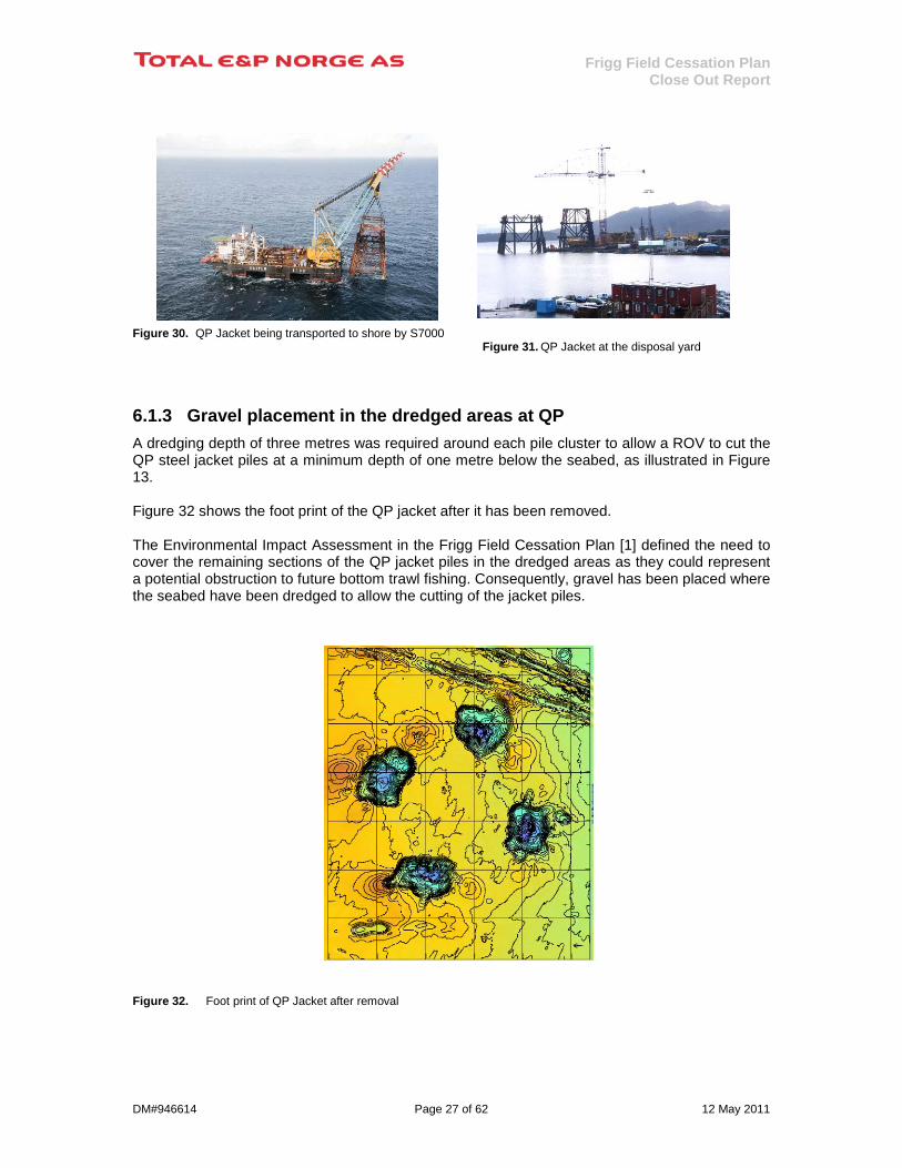
6.1.3 Gravel placement in the dredged areas at QP A dredging depth of three metres was required around each pile cluster to allow a ROV to cut the QP steel jacket piles at a minimum depth of one metre below the seabed, as illustrated in Figure 13. Figure 32 shows the foot print of the QP jacket after it has been removed. The Environmental Impact Assessment in the Frigg Field Cessation Plan [1] defined the need to cover the remaining sections of the QP jacket piles in the dredged areas as they could represent a potential obstruction to future bottom trawl fishing. Consequently, gravel has been placed where the seabed have been dredged to allow the cutting of the jacket piles. Figure 32. Foot print of QP Jacket after removal

Frigg Field Cessation Plan Close Out Report
DM#946614 Page 28 of 62 12 May 2011
6.2 TP1 Platform Table 9 summarises the overall weight removed from the TP1 concrete platform.
TP1 Platform Weight removed (tonne) Topsides 7 443 External steelwork 578 Sum 8 021
Table 9. Weight of the material removed from TP1 platform
6.2.1 TP1 Topsides The removal activities were based on a combined reverse installation method. 505 tonnes were removed piece small and the rest of the modules were lifted off by S7000. The first hook down campaign took place from March 2005 to July 2006 when the accommodation on QP was closed. The work continued in January 2007 when the flotel Port Reval was bridge linked to TP1. Access to QP and TCP2 platforms was possible using the existing bridges between the Frigg Central Complex installations.
Figure 33. TP1 Topside before removal
Figure 34. Last module ready for removal by S7000 The MSF was cut loose from the two concrete columns in May 2007. Special securing brackets were installed to ensure it remained safely in position during the winter storms, see Figure 35. In July 2009 the MSF, weighing 3,016 tonnes, was removed by S7000 in one lift. It was not required to confirm the exact weigh and centre of gravity as the lift weight was within one crane’s lift capacity. Using only one crane the S7000 was able to place the MSF on its own deck for transport to Aker Stord disposal yard, see Figure 36.

Frigg Field Cessation Plan Close Out Report
DM#946614 Page 29 of 62 12 May 2011
Figure 35. TP1 MSF resting on top of the concrete columns
Figure 36. TP1 MSF loaded onto the Aker Stord disposal Yard by S7000
6.2.2 TP1 External Steelwork The principle established in the approved Cessation Plan was that any external steelwork attached to the concrete substructure representing a future potential obstacle for bottom trawl fishing near the platform should be removed as far as reasonably practicable. The external steelwork attached to the TP1 concrete structure was mainly: • External risers entering the concrete columns at top of the caisson • Utility risers from the topsides • Boat bumpers • External ladders and platforms (used for emergency evacuation) • Vent pipes with supports (used during the installation) • Various sheave assemblies, roller guides and blocks
Figure 37. External steelwork TP1 Concrete Substructure
Abseilers were used extensively to remove the items above water. Below water the steelwork was cut using various underwater cutting tools attached to a ROV operated from the platform deck. All the steel was brought to the deck and placed in containers and transported to the onshore disposal facilities where all was recycled. Two utility riser support frames on each concrete column at -6m and -17m each weighing about five tonnes have not been removed. A detailed survey showed that the frames were closer to the concrete wall than shown on the installation drawings. After an overall evaluation considering the limited space, risks involved in working in the splash zone and that they would not represent any obstructions to fishing as they would fall on top of the caisson, DECC has agreed to TOTAL Norge’s recommendation not to remove these frames.
Frigg Field Cessation Plan Close Out Report
DM#946614 Page 30 of 62 12 May 2011
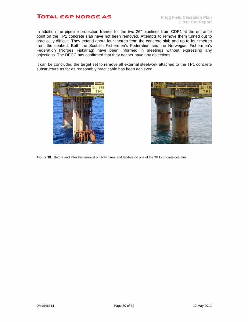
In addition the pipeline protection frames for the two 26” pipelines from CDP1 at the entrance point on the TP1 concrete slab have not been removed. Attempts to remove them turned out to practically difficult. They extend about four metres from the concrete slab and up to four metres from the seabed. Both the Scottish Fishermen’s Federation and the Norwegian Fishermen’s Federation (Norges Fiskarlag) have been informed in meetings without expressing any objections. The DECC has confirmed that they neither have any objections. It can be concluded the target set to remove all external steelwork attached to the TP1 concrete substructure as far as reasonably practicable has been achieved. Figure 38. Before and after the removal of utility risers and ladders on one of the TP1 concrete columns.
Frigg Field Cessation Plan Close Out Report
DM#946614 Page 31 of 62 12 May 2011
6.3 CDP1 Platform Table 10 summarises the overall weight removed from the CDP1 concrete platform.
CDP1 Platform Weight removed (tonne) Topsides 6 443 External steelwork 0 Sum 6 443
Table 10. Weight of the material removed from CDP1 platform The only external steelwork attached to the outer concrete wall on CDP1 was the boat bumpers and ladders which were removed a few years after the platform was installed.
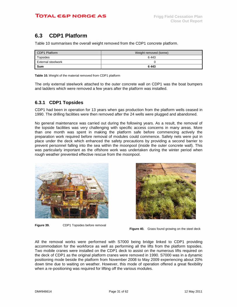
6.3.1 CDP1 Topsides CDP1 had been in operation for 13 years when gas production from the platform wells ceased in 1990. The drilling facilities were then removed after the 24 wells were plugged and abandoned. No general maintenance was carried out during the following years. As a result, the removal of the topside facilities was very challenging with specific access concerns in many areas. More than one month was spent in making the platform safe before commencing actively the preparation work required before removal of modules could commence. Safety nets were put in place under the deck which enhanced the safety precautions by providing a second barrier to prevent personnel falling into the sea within the moonpool (inside the outer concrete wall). This was particularly important as the offshore work was undertaken during the winter period when rough weather prevented effective rescue from the moonpool.
Figure 39. CDP1 Topsides before removal
Figure 40. Grass found growing on the steel deck All the removal works were performed with S7000 being bridge linked to CDP1 providing accommodation for the workforce as well as performing all the lifts from the platform topsides. Two mobile cranes were installed on the CDP1 deck to assist on the numerous lifts required on the deck of CDP1 as the original platform cranes were removed in 1990. S7000 was in a dynamic positioning mode beside the platform from November 2008 to May 2009 experiencing about 20% down time due to waiting on weather. However, this mode of operation offered a great flexibility when a re-positioning was required for lifting off the various modules.

Frigg Field Cessation Plan Close Out Report
DM#946614 Page 32 of 62 12 May 2011
Manual piece small dismantling work was carried out to disconnect and split the modules. All the 18 modules and the piece small material were placed onto the deck of S7000 which transported the material to Aker Stord in Norway.
Figure 41. Four modules in one combine lift
Figure 42. Towards the end of removing the topside facilities
Frigg Field Cessation Plan Close Out Report
DM#946614 Page 33 of 62 12 May 2011
6.4 Removal of Pipelines and Cables in the UK Sector
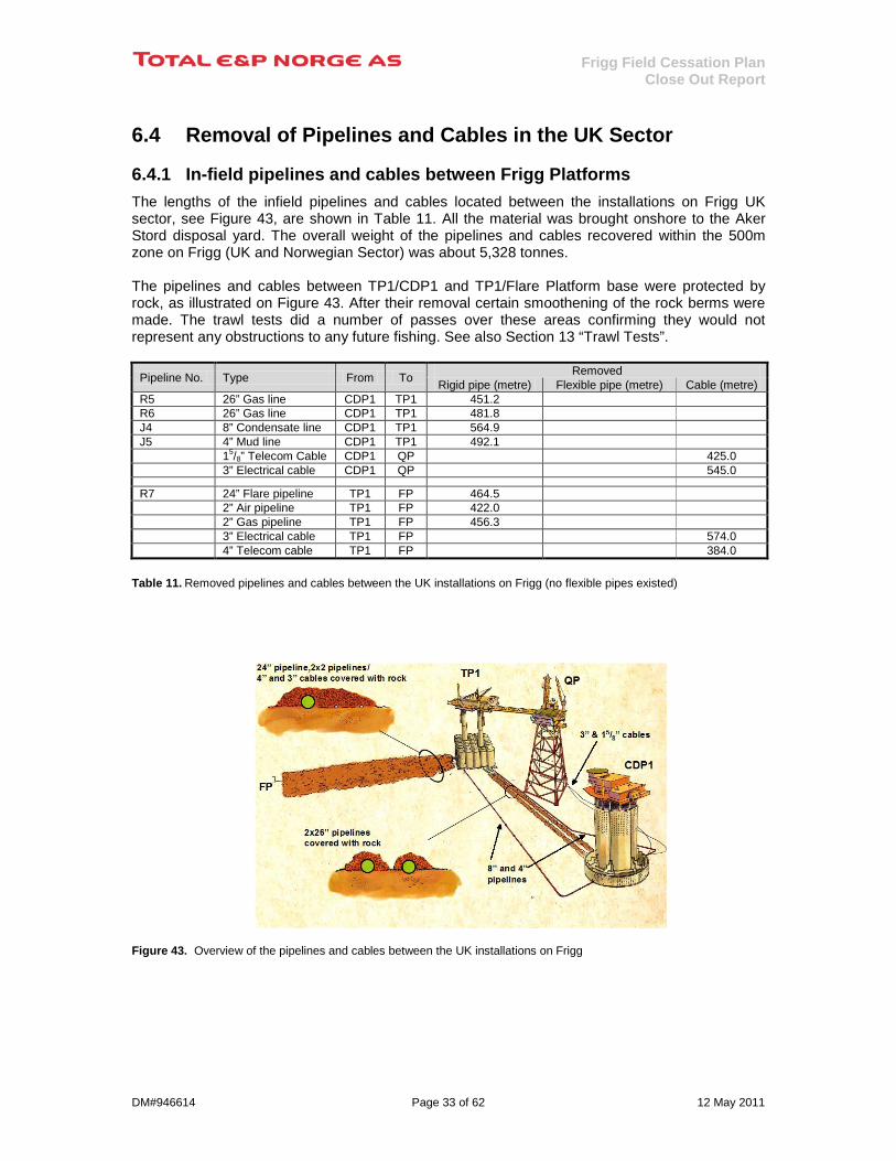
6.4.1 In-field pipelines and cables between Frigg Platforms The lengths of the infield pipelines and cables located between the installations on Frigg UK sector, see Figure 43, are shown in Table 11. All the material was brought onshore to the Aker Stord disposal yard. The overall weight of the pipelines and cables recovered within the 500m zone on Frigg (UK and Norwegian Sector) was about 5,328 tonnes. The pipelines and cables between TP1/CDP1 and TP1/Flare Platform base were protected by rock, as illustrated on Figure 43. After their removal certain smoothening of the rock berms were made. The trawl tests did a number of passes over these areas confirming they would not represent any obstructions to any future fishing. See also Section 13 “Trawl Tests”.
Pipeline No. Type From To Removed Rigid pipe (metre) Flexible pipe (metre) Cable (metre)
R5 26” Gas line CDP1 TP1 451.2 R6 26” Gas line CDP1 TP1 481.8 J4 8” Condensate line CDP1 TP1 564.9 J5 4” Mud line CDP1 TP1 492.1 15/8” Telecom Cable CDP1 QP 425.0 3” Electrical cable CDP1 QP 545.0
R7 24” Flare pipeline TP1 FP 464.5 2” Air pipeline TP1 FP 422.0 2” Gas pipeline TP1 FP 456.3 3” Electrical cable TP1 FP 574.0 4” Telecom cable TP1 FP 384.0
Table 11. Removed pipelines and cables between the UK installations on Frigg (no flexible pipes existed) Figure 43. Overview of the pipelines and cables between the UK installations on Frigg

Frigg Field Cessation Plan Close Out Report
DM#946614 Page 34 of 62 12 May 2011
Concrete saddles/blocks 35 concrete blocks have been recovered which is one more than quoted in the Cessation Plan. Mattresses Within the 500m zone of the Frigg installations 160 concrete mattresses have been removed by the contractor removing the pipelines and cables. Whether they were removed from the UK or Norwegian sector of the field was not recorded.
Figure 44. Concrete saddles removed from pipelines
Bags Some concrete/grout and sand bags were impossible to remove as they disintegrated when attempting a removal. The Multi Beam Echo Sounder survey performed after the removal campaign shows no mattresses have been left. So it is considered that the mattresses originally in place have been removed. This is supported by the fact that the two trawl sweeps in the area in question were successful. Reference is also made to Section 11 addressing the debris clearance campaigns during and after the offshore removal works were completed.
6.4.2 Removal of Alwyn Disused Pipeline Section The removal of the disused section of the 24” pipeline from Alwyn to TP1 within the Frigg 500m zone is not part of the Frigg Field Cessation Plan (see also below Section 6.4.3). However, the Cessation Plan states that it would be the intention to remove the pipeline from TP1 following the following criteria:- • remove to a point where they are trenched, or • remove to the boundary of the 500m zone around TP1 Table 12 gives a summary of the length of the disused 24” pipeline section removed next to TP1.
From To Removed Rigid pipe (metre) Flexible pipe (metre) Cable (metre)
Alwyn TP1 73 0 0
Table 12. Third Party pipeline removed from the UK Sector of the Frigg Field
6.4.3 24” and 32” Disused Pipeline Sections to/from TP1 Parts of the disused pipeline sections belonging to PL6 (32” Frigg UK Pipeline from TP1) and PL336 (24” from Alwyn to TP1) after the bypass of TP1 in 2004 are still in place within the 500m zone of Frigg. After the Frigg Field Cessation Plan was submitted the owner TOTAL E&P UK Ltd. has received a letter from the DECC (previously named DTI) that they are content, with reference to DECC’s Interim Pipeline Regime (IPR), with the owner’s proposal that these two disused pipeline sections can be left in place until such a time the whole pipeline systems are decommissioned. These disused sections are to be included in the respective decommissioning programmes when being submitted for the complete pipeline systems PL6 and PL336 sometime in the future. Until then these sections will be subject to a regular survey.
Frigg Field Cessation Plan Close Out Report
DM#946614 Page 35 of 62 12 May 2011
7 Onshore Disposal
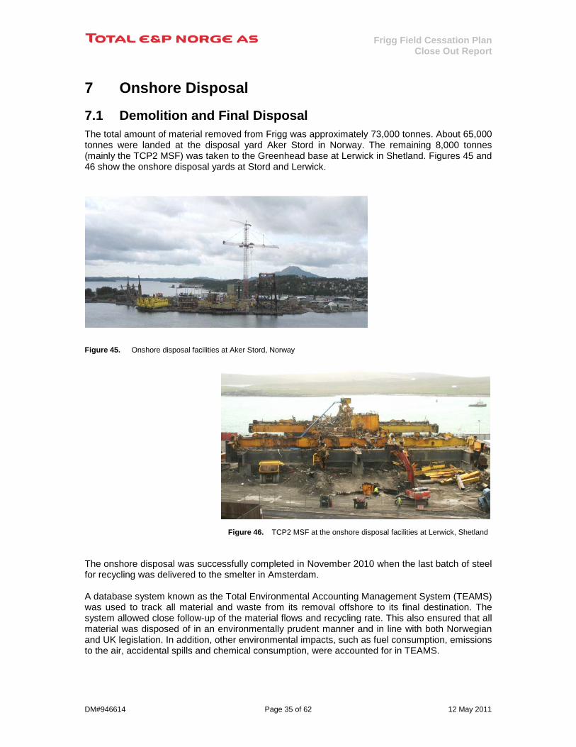
7.1 Demolition and Final Disposal The total amount of material removed from Frigg was approximately 73,000 tonnes. About 65,000 tonnes were landed at the disposal yard Aker Stord in Norway. The remaining 8,000 tonnes (mainly the TCP2 MSF) was taken to the Greenhead base at Lerwick in Shetland. Figures 45 and 46 show the onshore disposal yards at Stord and Lerwick.
Figure 45. Onshore disposal facilities at Aker Stord, Norway
Figure 46. TCP2 MSF at the onshore disposal facilities at Lerwick, Shetland The onshore disposal was successfully completed in November 2010 when the last batch of steel for recycling was delivered to the smelter in Amsterdam. A database system known as the Total Environmental Accounting Management System (TEAMS) was used to track all material and waste from its removal offshore to its final destination. The system allowed close follow-up of the material flows and recycling rate. This also ensured that all material was disposed of in an environmentally prudent manner and in line with both Norwegian and UK legislation. In addition, other environmental impacts, such as fuel consumption, emissions to the air, accidental spills and chemical consumption, were accounted for in TEAMS.

Frigg Field Cessation Plan Close Out Report
DM#946614 Page 36 of 62 12 May 2011
The weights in Table 13 include the overall weights including hazardous, electric and electronic wastes received onshore from Frigg. The final recorded overall weight was at the end about 3.4 % less than estimated.
Facility Materials Disposed (tonne) CDP1 Topsides 6,443 DP1 Jacket 7,364 DP2 Topsides 4,002 DP2 Jacket 11,122 QP Topsides 3,063 QP Jacket 5,243 TCP2 External Steelwork 739 TCP2 Topsides 21,433 TP1 External Steelwork 578 TP1 Topsides 7,443 Debris 222 Pipelines and Cables 5,328 Sum 72,980
Table 13. Weight of materials recorded in TEAMS for the Frigg facilities It should be noted that the weight of the DP2 jacket in Table 13 includes the weight of the MSF (estimated to 917 tonnes), piles and grout (estimated to 1,620 tonnes). Hence the actual weight of the jacket was about 8,585 tonnes. Figure 47. Origins of the disposed materials from the Frigg facilities Most of the modules were all within the reach of the excavators with hydraulic shear and material handler machines, so the demolition work were based on using these machines to the extent possible. If the modules contained heavy equipment or equipment located up high, the equipment was disconnected or cut free from pipelines and other connected items before it was lifted down to ground for further dismantling into smaller pieces sized to fit into the hydraulic stationary shear. For the largest module the top part of the module was manually cut and lifted down to ground level in smaller pieces until the high of the module were within the reach of the excavator’s hydraulic shear.
Figure 48. Last sign of Frigg
0
5000
10000
15000
20000
25000
TCP2 TP1 CDP1 DP2 QP DP1 Sealines Debris

Frigg Field Cessation Plan Close Out Report
DM#946614 Page 37 of 62 12 May 2011
After the modules had been inspected and removed or isolated dangerous and hazardous materials, they were cut to transportable sizes by disconnecting flanges and cutting the pipes by flame cutting. All flange disconnection and cuts were engineered and marked so that the pipe support integrity always was maintained as the cutting and removal process proceeded.
Figure 49. Demolition of modules using large excavators
Dismantling of the main structure would commence by using the hydraulic shear excavator after the module had been stripped for all inventories. Plate thicknesses were within the range of the capacity of the hydraulic nibbler and all the structural members were cut into sizes suitable for the hydraulic stationary shear.
7.2 Hazardous Waste Close attention has been paid to identification and removal of hazardous waste, including asbestos, mercury, lead, batteries, hydrocarbons and naturally occurring radioactive material. This particular work has been conducted on a reimbursable basis with the contractors. This had a very positive impact on the entire operation as it has encouraged the contractors to conduct a detailed inspection of countless number of material and equipment items. Nearly one thousand samples have been taken during the course of the onshore operations to confirm the substances. The total amount of hazardous waste from Frigg recovered and sent for special treatment and disposal added up to about 1,620 tonnes. Figure 50. Sorted hazardous and EE waste material removed from modules for transport to waste handling contractor
Figure 51. Material containing Asbestos which have been isolated before transport to final disposal site
Frigg Field Cessation Plan Close Out Report
DM#946614 Page 38 of 62 12 May 2011
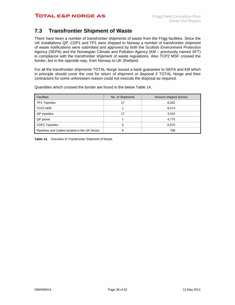
7.3 Transfrontier Shipment of Waste There have been a number of transfrontier shipments of waste from the Frigg facilities. Since the UK installations QP, CDP1 and TP1 were shipped to Norway a number of transfrontier shipment of waste notifications were submitted and approved by both the Scottish Environment Protection Agency (SEPA) and the Norwegian Climate and Pollution Agency (Klif – previously named SFT) in compliance with the transfrontier shipment of waste regulations. Also TCP2 MSF crossed the border, but in the opposite way, from Norway to UK Shetland. For all the transfrontier shipments TOTAL Norge issued a bank guarantee to SEPA and Klif which in principle should cover the cost for return of shipment or disposal if TOTAL Norge and their contractors for some unforeseen reason could not execute the disposal as required. Quantities which crossed the border are found in the below Table 14.
Facilities No. of Shipments Amount shipped (tonne)
TP1 Topsides 17 8,262
TCP2 MSF 1 8,474
QP topsides 17 3,315
QP jacket 1 4,775
CDP1 Topsides 5 6,570
Pipelines and Cables located in the UK Sector 6 798 Table 14. Overview of Transfrontier Shipment of Waste
Frigg Field Cessation Plan Close Out Report
DM#946614 Page 39 of 62 12 May 2011
8 Safety Performance
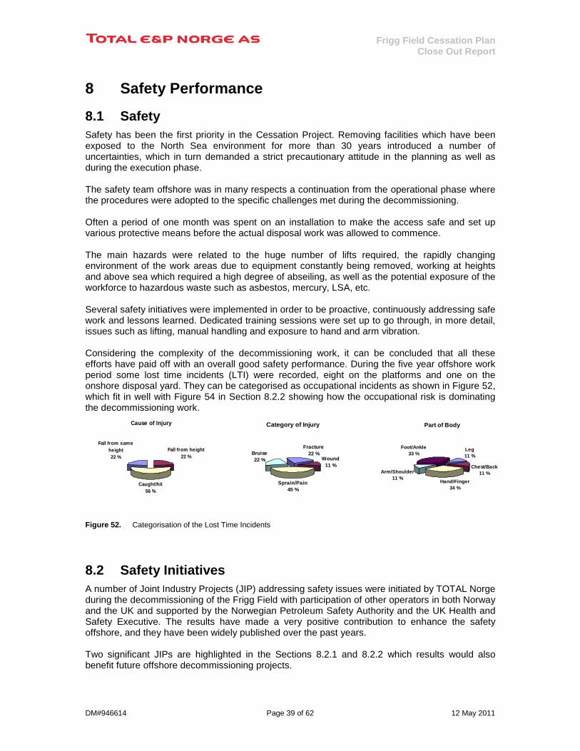
8.1 Safety Safety has been the first priority in the Cessation Project. Removing facilities which have been exposed to the North Sea environment for more than 30 years introduced a number of uncertainties, which in turn demanded a strict precautionary attitude in the planning as well as during the execution phase. The safety team offshore was in many respects a continuation from the operational phase where the procedures were adopted to the specific challenges met during the decommissioning. Often a period of one month was spent on an installation to make the access safe and set up various protective means before the actual disposal work was allowed to commence. The main hazards were related to the huge number of lifts required, the rapidly changing environment of the work areas due to equipment constantly being removed, working at heights and above sea which required a high degree of abseiling, as well as the potential exposure of the workforce to hazardous waste such as asbestos, mercury, LSA, etc. Several safety initiatives were implemented in order to be proactive, continuously addressing safe work and lessons learned. Dedicated training sessions were set up to go through, in more detail, issues such as lifting, manual handling and exposure to hand and arm vibration. Considering the complexity of the decommissioning work, it can be concluded that all these efforts have paid off with an overall good safety performance. During the five year offshore work period some lost time incidents (LTI) were recorded, eight on the platforms and one on the onshore disposal yard. They can be categorised as occupational incidents as shown in Figure 52, which fit in well with Figure 54 in Section 8.2.2 showing how the occupational risk is dominating the decommissioning work.
Figure 52. Categorisation of the Lost Time Incidents
8.2 Safety Initiatives A number of Joint Industry Projects (JIP) addressing safety issues were initiated by TOTAL Norge during the decommissioning of the Frigg Field with participation of other operators in both Norway and the UK and supported by the Norwegian Petroleum Safety Authority and the UK Health and Safety Executive. The results have made a very positive contribution to enhance the safety offshore, and they have been widely published over the past years. Two significant JIPs are highlighted in the Sections 8.2.1 and 8.2.2 which results would also benefit future offshore decommissioning projects.
Category of Injury
Fracture22 %
Wound11 %
Sprain/Pain45 %
Bruise22 %
Cause of Injury
Fall from same height22 %
Fall from height22 %
Caught/hit56 %
Part of Body
Leg11 %
Chest/Back11 %
Hand/Finger34 %
Arm/Shoulder11 %
Foot/Ankle33 %
Frigg Field Cessation Plan Close Out Report
DM#946614 Page 40 of 62 12 May 2011
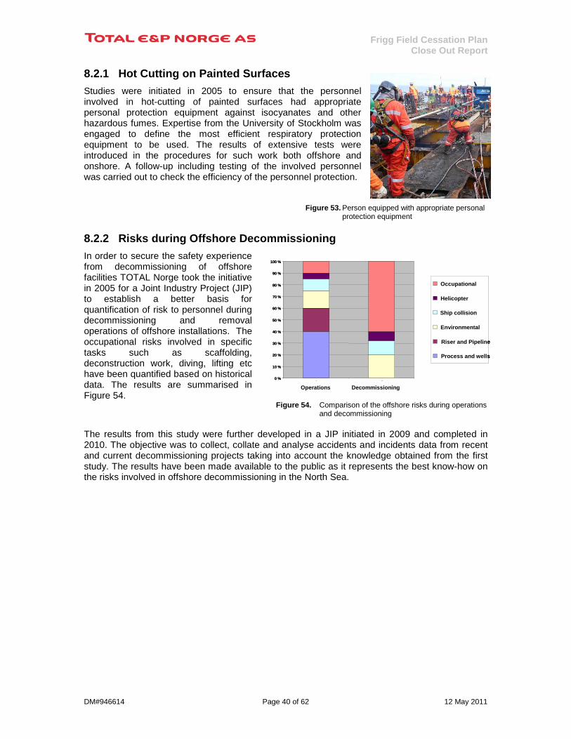
8.2.1 Hot Cutting on Painted Surfaces Studies were initiated in 2005 to ensure that the personnel involved in hot-cutting of painted surfaces had appropriate personal protection equipment against isocyanates and other hazardous fumes. Expertise from the University of Stockholm was engaged to define the most efficient respiratory protection equipment to be used. The results of extensive tests were introduced in the procedures for such work both offshore and onshore. A follow-up including testing of the involved personnel was carried out to check the efficiency of the personnel protection.
Figure 53. Person equipped with appropriate personal protection equipment
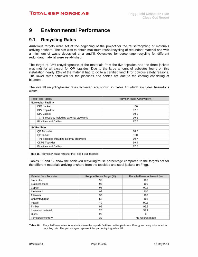
8.2.2 Risks during Offshore Decommissioning In order to secure the safety experience from decommissioning of offshore facilities TOTAL Norge took the initiative in 2005 for a Joint Industry Project (JIP) to establish a better basis for quantification of risk to personnel during decommissioning and removal operations of offshore installations. The occupational risks involved in specific tasks such as scaffolding, deconstruction work, diving, lifting etc have been quantified based on historical data. The results are summarised in Figure 54.
Figure 54. Comparison of the offshore risks during operations and decommissioning
The results from this study were further developed in a JIP initiated in 2009 and completed in 2010. The objective was to collect, collate and analyse accidents and incidents data from recent and current decommissioning projects taking into account the knowledge obtained from the first study. The results have been made available to the public as it represents the best know-how on the risks involved in offshore decommissioning in the North Sea.
0 %
10 %
20 %
30 %
40 %
50 %
60 %
70 %
80 %
90 %
100 %
1 2
Occupational
Helicopter
Ship collision
Environmental
Riser and Pipeline
Process and wells
0 %
10 %
20 %
30 %
40 %
50 %
60 %
70 %
80 %
90 %
100 %
1 2
Occupational
Helicopter
Ship collision
Environmental
Riser and Pipeline
Process and wells
Operations Decommissioning
Frigg Field Cessation Plan Close Out Report
DM#946614 Page 41 of 62 12 May 2011
9 Environmental Performance
9.1 Recycling Rates Ambitious targets were set at the beginning of the project for the reuse/recycling of materials arriving onshore. The aim was to obtain maximum reuse/recycling of redundant material and with a minimum of waste deposited at a landfill. Objectives for percentage recycling for different redundant material were established. The target of 98% recycling/reuse of the materials from the five topsides and the three jackets was met for all except for QP topsides. Due to the large amount of asbestos found on this installation nearly 12% of the material had to go to a certified landfill for obvious safety reasons. The lower rates achieved for the pipelines and cables are due to the coating consisting of bitumen. The overall recycling/reuse rates achieved are shown in Table 15 which excludes hazardous waste.
Frigg Field Facility Recycle/Reuse Achieved (%) Norwegian Facility DP1 Jacket 100 DP2 Topsides 97.7 DP2 Jacket 99.9 TCP2 Topsides including external steelwork 99.1 Pipelines and Cables 87.6 UK Facilities QP Topsides 88.8 QP Jacket 100 TP1 Topsides including external steelwork 99.7 CDP1 Topsides 99.4 Pipelines and Cables 87.6
Table 15. Recycling/Reuse rates for the Frigg Field facilities Tables 16 and 17 show the achieved recycling/reuse percentage compared to the targets set for the different materials arriving onshore from the topsides and steel jackets on Frigg.
Material from Topsides Recycle/Reuse Target (%) Recycle/Reuse Achieved (%) Black steel 99 100 Stainless steel 98 100 Copper 95 99.3 Aluminium 98 100 Titanium 98 100 Concrete/Grout 50 100 Plastic 40 90.5 Timber 95 98.9 Insulation material 20 94.2 Glass 20 0 Furniture/Inventory 30 No records made
Table 16. Recycle/Reuse rates for materials from the topside facilities on five platforms. Energy recovery is included in
recycling rate. The percentages represent the part not going to landfill.
Frigg Field Cessation Plan Close Out Report
DM#946614 Page 42 of 62 12 May 2011
Material from Jackets Recycle/Reuse Target (%) Recycle/Reuse Achieved (%) Black steel 100 100 Aluminium 100 100 Zink 100 100 Copper 100 100
Table 17. Recycle/Reuse rates for materials from the three jackets
9.2 Comparison with the Assumptions in the EIA An assessment of the actual environmental impact caused by the approved disposal alternative has been compared with the assumptions made in the Environmental Impact Assessment (EIA) reported as Part 2 in the Frigg Field Cessation Plan [1]. The disposal of the Frigg Field facilities consumed a significant amount of fuel (energy), about 40,000 tonnes, which again has given emissions to air of CO2 and NOX. This is however in full compliance with the approved Cessation Plan. The energy consumption is 44% higher while the total energy
impact is 38% higher than initially estimated in the EIA.
The discharge of CO2
has been estimated to be about 250,000 tonnes, including the re-melting of the metal, which is about the double compared to estimated value in the EIA. The “piece small” removal technique represents a considerable higher CO2 discharge due to the long period with use a flotel kept stationary with a dynamic positioning system during the offshore works and the large number of shipments of materials with supply vessels.
Direct discharges
to sea during the offshore removal and onshore demolition work have been negligible in volume and no measurable impacts have been documented. The dredging of the drill cuttings layer under/near the DP2 location may however have caused a total re-distribution of this material with the potential for leakage of present pollutants with associated exposure to water masses and fauna present. This is similar to the assumptions made in the EIA and the “small negative” impact is still considered relevant.
Some local and temporary physical/habitat effects
on the offshore seabed is documented however are negligible spatially and will have a natural restitution. The main pitches have also been mitigated by rock-dumping. Hence a “small negative” impact is considered relevant.
Temporary nuisances on local community/ have been limited and no particular issues have been recorded. Onshore demolition and metal handling activities still generate noise, increased local traffic, and the inshore DP2 jacket dismantling campaign might have caused some nuisance. Hence a “small negative” impact on the aesthetic
is considered relevant.
The material management
remains “large positive” with a high recycling rate as shown in Tables 15 and 16 under Section 9.1. The use of temporary materials is about 2,000 tonnes and in additions comes the 4,000 tonnes buoyancy tanks used to remove the DP2 Jacket (see Section 5.1.2).
The potential for littering
effects is more or less eliminated in the short term due to extensive debris removal coupled with sonar surveys and trawl test for verification. At least in the short term perspective this potential is very low. In the longer term there is a littering potential related to deterioration of the concrete structures left in place. The EIA stipulation of a “small negative” littering potential is hence considered still valid.
Table 18 compares the assumptions made in the Frigg Field Cessation Plan/EIA [1] with the actual environmental performance.

Frigg Field Cessation Plan Close Out Report
DM#946614 Page 43 of 62 12 May 2011
Assumed in the EIA
(ref. Frigg Field Cessation Plan, Part 2 [1]) As executed / End disposal
Energy consumption (1000 GJ) 1 577 2 250
Total Energy (1000 GJ) 2 377 3 306
CO2 emissions (1000 tonnes) 130 250
Discharges to sea Small negative Small negative
Phys./habitat effects Moderate negative Small negative
Aesthetic Moderate negative Small negative
Material management Large positive Large positive
Littering Small negative Small negative Table 18. : Comparison between the EIA assessments [1] vs. actual execution and end disposal
9.3 Reuse of equipment The sale of material and equipment from the inventory (modules) sent onshore was not as successful as had been first envisaged. Despite the services of a broker company to manage the marketing the efforts did not provide the environmental rewards which had been projected. Some of the more important sale or re-use of equipment is shown on the following Figures 55, 56 and 57. Figure 55. Cranes and booms sold
Figure 56. Inventory from TCP2 M35 sold
Figure 57. DP2 Jacket pile cluster (left) and QP jacket section (right) used as quay foundation at Aker Stord
Frigg Field Cessation Plan Close Out Report
DM#946614 Page 44 of 62 12 May 2011
10 General Visual Inspection of the Concrete Substructures
Surveys of the conditions of the concrete substructures TCP2 (in the Norwegian sector) and TP1 and CDP1 (in the UK Sector) and the adjacent seabed’s have been performed after the approved offshore removal programme of the facilities have been completed.
10.1 Below-Water Inspection A General Visual Inspections (GVI) of the below-water parts of the concrete substructures TCP2, TP1 and CDP1 and the adjacent seabed was performed during January 2010. The GVI was performed using a ROV deployed from a vessel documenting the inspections on colour videos. The inspection was performed very much in line with the past below-water inspection practice during the operational phase. A more detailed inspection was performed on TCP2 and TP1 in the transition between the caisson and the columns exposed to fatigue. Status of the repaired bottom diaphragm walls on CDP1 was also inspected. The seabed was covered up to 15m from the concrete slabs. A comprehensive documentation of the below-water condition of the three concrete substructures was obtained concluding that no deterioration has taken place which could represent a possible consequence for the safety of other users of the sea.
10.2 Above-Water Inspection An above-water photo survey was performed in September 2010 using a helicopter. A comprehensive set of colour photos were taken documenting the above-water condition of the substructures after the topside facilities have been removed. The photo documentation has been reviewed concluding that no deterioration has taken place which could represent a possible consequence for the safety of other users of the sea.
10.3 Future monitoring A procedure has been established outlining the requirements for the assessment of the above-water condition in line with the Permit Conditions for leaving in place the concrete substructures in accordance with OSPAR Decision 98/3. An assessment shall be made when all three Aids to Navigations (AtoN) are inspected. At present time the AtoNs are expected to be replaced every fourth year, however, this may be changed depending on the in-service experience. First replacement is planned during summer 2011. Replacement of an AtoN may take place in between due to unexpected malfunctioning. Any changes to the frequency of assessing the above-water condition of the concrete substructures will be subject for approval by the relevant national authority.
The assessment based on the visual observations will be done by a competent person onshore with a report issued to the authorities. Any deterioration of the above-water condition will be recorded. Possible consequences for the safety of other users of the sea will be assessed. Any required actions will be determined in consultation with the relevant national authorities as shown in Table 19.
Concrete Substructure Assessment Report to Copy of Assessment Report CDP1 in UK Sector UK Health Safety Executive Norwegian Petroleum Safety Authority TP1 in UK Sector UK Health Safety Executive Norwegian Petroleum Safety Authority TCP2 in Norwegian Sector Norwegian Petroleum Safety Authority UK Health Safety Executive
Table 19. Authorities to receive the assessment of the above-water conditions of the concrete substructures
Frigg Field Cessation Plan Close Out Report
DM#946614 Page 45 of 62 12 May 2011
11 Debris Clearance The objective of the debris clearance was to remove any debris that could represent an obstruction to a future bottom trawl fishing within the 500m safety zone around the locations of the Frigg installations. Two debris clearance campaigns have been performed during the decommissioning of the Frigg Field. The first one was done in June 2008 covering the area around TCP2/TP1/QP. Upon completion of all offshore removal a debris clearance campaign covering the 500m zone on Frigg was performed in February 2010.
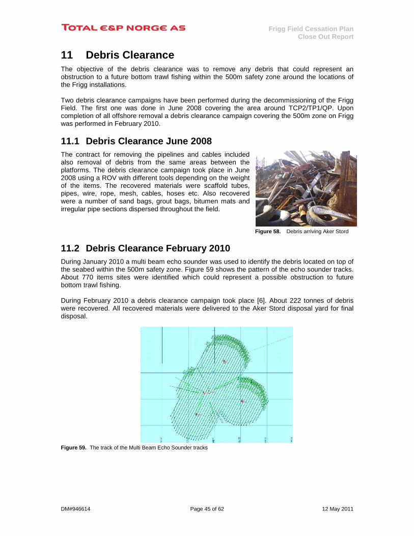
11.1 Debris Clearance June 2008 The contract for removing the pipelines and cables included also removal of debris from the same areas between the platforms. The debris clearance campaign took place in June 2008 using a ROV with different tools depending on the weight of the items. The recovered materials were scaffold tubes, pipes, wire, rope, mesh, cables, hoses etc. Also recovered were a number of sand bags, grout bags, bitumen mats and irregular pipe sections dispersed throughout the field.
Figure 58. Debris arriving Aker Stord
11.2 Debris Clearance February 2010 During January 2010 a multi beam echo sounder was used to identify the debris located on top of the seabed within the 500m safety zone. Figure 59 shows the pattern of the echo sounder tracks. About 770 items sites were identified which could represent a possible obstruction to future bottom trawl fishing. During February 2010 a debris clearance campaign took place [6]. About 222 tonnes of debris were recovered. All recovered materials were delivered to the Aker Stord disposal yard for final disposal. Figure 59. The track of the Multi Beam Echo Sounder tracks

Frigg Field Cessation Plan Close Out Report
DM#946614 Page 46 of 62 12 May 2011
12 Environmental Surveys Environmental surveys of the seabed have been taken on a regular basis within the Frigg Field since 1992. However, to document the condition of the seabed before and after the decommissioning of the field the following sampling dates have been used as a reference: • Pre-removal survey: May 2003 • During the removal phase: May 2006 • Post-removal survey: May 2010 The time line for these environmental surveys in relation to the main milestones in the decommissioning of the Frigg facilities is shown in Figure 60.
Figure 60. Time line of the seabed sampling performed on Frigg Field The program for 2010 was based on the results obtained from the previous monitoring programs in 2003 and 2006 and contained both chemical and biological analyses of the sediments, see Figure 61. Figure 61. Location of the sampling stations in 2003, 2006 and 2010 on the Frigg Field The conclusion from the 2010 survey is that all stations within the Frigg Field consist mainly of sand (94-99 %) where the content of the total organic matter is low (0.45-0.76 %). The concentrations of the Total Hydrocarbon Content (THC) are low (4-11 mg/kg), and none of the measured THC-concentrations are above the Level of Significant Contamination2
2 Level of Significant Contamination (LSC) is a set of reference values defined by the Norwegian Climate and Pollution Agency (Klif – previously named SFT) based on seabed samples taken in June 1997 for the region named Sub-Region North, Region II on the Norwegian Continental Shelf.
(LSC), as shown on Figure 62
2003 2004 2005 2006 2007 2008 2009 2010
Seabed sampling
Seabed
samplin
g
Seabed
samplin
g
Gas pro
duction st
opped
Offshore
remova
l star
ted
Offshore
remova
l complet
ed
Debris
clea
rance
2003 2004 2005 2006 2007 2008 2009 2010
Seabed sampling
Seabed
samplin
g
Seabed
samplin
g
Gas pro
duction st
opped
Offshore
remova
l star
ted
Offshore
remova
l complet
ed
Debris
clea
rance
6637800
6638000
6638200
6638400
6638600
6638800
6639000
6639200
6639400
6639600
446600 446800 447000 447200 447400 447600 447800 448000 448200 448400 448600
TCP 2TP1
CDP 1
DP 2
Frigg Field Cessation Plan Close Out Report
DM#946614 Page 47 of 62 12 May 2011
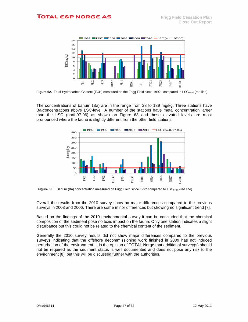
Figure 62. Total Hydrocarbon Content (TCH) measured on the Frigg Field since 1992 compared to LSC97-06 (red line). The concentrations of barium (Ba) are in the range from 28 to 189 mg/kg. Three stations have Ba-concentrations above LSC-level. A number of the stations have metal concentration larger than the LSC (north97-06) as shown on Figure 63 and these elevated levels are most pronounced where the fauna is slightly different from the other field stations. Figure 63. Barium (Ba) concentration measured on Frigg Field since 1992 compared to LSC97-06 (red line).
Overall the results from the 2010 survey show no major differences compared to the previous surveys in 2003 and 2006. There are some minor differences but showing no significant trend [7]. Based on the findings of the 2010 environmental survey it can be concluded that the chemical composition of the sediment pose no toxic impact on the fauna. Only one station indicates a slight disturbance but this could not be related to the chemical content of the sediment. Generally the 2010 survey results did not show major differences compared to the previous surveys indicating that the offshore decommissioning work finished in 2009 has not induced perturbation of the environment. It is the opinion of TOTAL Norge that additional survey(s) should not be required as the sediment status is well documented and does not pose any risk to the environment [8], but this will be discussed further with the authorities.
0
50
100
150
200
250
300
350
400
FRI1
FRI2
FRI3
FRIX
2
FRI4
FRIX
1
FRI11
FRI24
FRI25
FRI27
FRI10
R
Ba (m
g/kg)
1992 1997 2000 2003 2010 LSC (north 97-06)
0
2
4
6
8
10
12
14
16
18
FRI1
FRI2
FRI3
FRIX
2
FRI4
FRIX
1
FRI11
FRI24
FRI25
FRI27
FRI10
R
THC (
mg/kg
)
1992 1997 2000 2003 2006 2010 LSC (north 97-06)

Frigg Field Cessation Plan Close Out Report
DM#946614 Page 48 of 62 12 May 2011
13 Trawl Tests Two trawl tests have been performed during the decommissioning of the Frigg Field. The first one was done in September 2008 covering the area around TCP2/TP1/QP (within yellow circle on Figure 65). Upon completion of all offshore removal works a second trawl test was performed in September 2010 covering the complete Frigg Field 500m safety zone (within yellow and blue circles on Figure 65). On both occasions the SFF Services Limited (SFF) supplied the trawler MV Solstice using representative bottom trawl equipment. On location the skipper of the trawler decided how to cover the defined trawl zone. The procedure by the SFF defined first a sweep using a “chain net” being dragged along the seabed. After a successful sweep a normal trawl net was to be used.
Figure 64. Trawler MV Solstice in action on Frigg
13.1 Trawl test in September 2008 The trawl test took place after the pipelines and cables with corresponding concrete blocks/saddles, mattresses and bags had been removed. The area of the trawl sweep covered the locations where the pipelines and cables had been laying. Both the “chain net” and the bottom trawl passed the area successfully. Consequently the SFF issued a “Clear Seabed Certificate” which is attached to Appendix 1, Table 25, documenting that the seabed covered was free from any obstructions which could prevent any future bottom trawl fishing. Figure 65. Area covered in the trawl tests in 2008 (within brown circle) and in 2010 (within brown and blue circles)
Frigg Field Cessation Plan Close Out Report
DM#946614 Page 49 of 62 12 May 2011
13.2 Trawl test in September 2010 The second trawl test was performed in August 2010 after all the offshore removal operations had been completed using the same trawler supplied by the SFF in 2008. This time the trawl sweep took place within the 500m safety zones of CDP1, DP2, DP1 and QP/TP1/TCP2 which also included the area covered in 2008. Figure 65 shows the area covered. Three locations prevented the “chain net” to pass. On one location the “chain net” got stuck and was lost and the trawler had to go to Shetland for a replacement before continuing. However, the bottom trawl sweep using a normal trawl net was performed successfully. An anchor, a steel pipe, a conductor pipe (sticking about 0.5m above the seabed) and the “chain net” were later removed from the seabed. Consequently, the SFF issued a clear seabed statement for the Frigg Field dated 19th January 2011 which is attached in Appendix 1, Table 26. This letter from the SFF Services Limited dated 19th January 2011, confirming the successful trawl test within the 500m zone of the Frigg Field, is considered as the completion date for the decommissioning work as defined in the approved Frigg Field Cessation Plan [1], the letters of approval [2], [3] & [4] and the OSPAR consultation document [5].
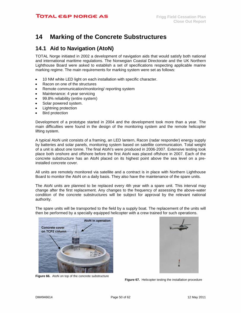
Frigg Field Cessation Plan Close Out Report
DM#946614 Page 50 of 62 12 May 2011
14 Marking of the Concrete Substructures
14.1 Aid to Navigation (AtoN) TOTAL Norge initiated in 2002 a development of navigation aids that would satisfy both national and international maritime regulations. The Norwegian Coastal Directorate and the UK Northern Lighthouse Board were asked to establish a set of specifications respecting applicable marine marking regime. The main requirements for marking system were set as follows: • 10 NM white LED light on each installation with specific character. • Racon on one of the structures • Remote communication/monitoring/ reporting system • Maintenance: 4 year servicing • 99.8% reliability (entire system) • Solar powered system. • Lightning protection • Bird protection Development of a prototype started in 2004 and the development took more than a year. The main difficulties were found in the design of the monitoring system and the remote helicopter lifting system. A typical AtoN unit consists of a framing, an LED lantern, Racon (radar responder) energy supply by batteries and solar panels, monitoring system based on satellite communication. Total weight of a unit is about one tonne. The final AtoN’s were produced in 2006-2007. Extensive testing took place both onshore and offshore before the first AtoN was placed offshore in 2007. Each of the concrete substructure has an AtoN placed on its highest point above the sea level on a pre-installed concrete cover. All units are remotely monitored via satellite and a contract is in place with Northern Lighthouse Board to monitor the AtoN on a daily basis. They also have the maintenance of the spare units. The AtoN units are planned to be replaced every 4th year with a spare unit. This interval may change after the first replacement. Any changes to the frequency of assessing the above-water condition of the concrete substructures will be subject for approval by the relevant national authority. The spare units will be transported to the field by a supply boat. The replacement of the units will then be performed by a specially equipped helicopter with a crew trained for such operations.
Figure 66. AtoN on top of the concrete substructure Figure 67. Helicopter testing the installation procedure
Spare Support
AtoN in operation
Concrete cover on TCP2 column
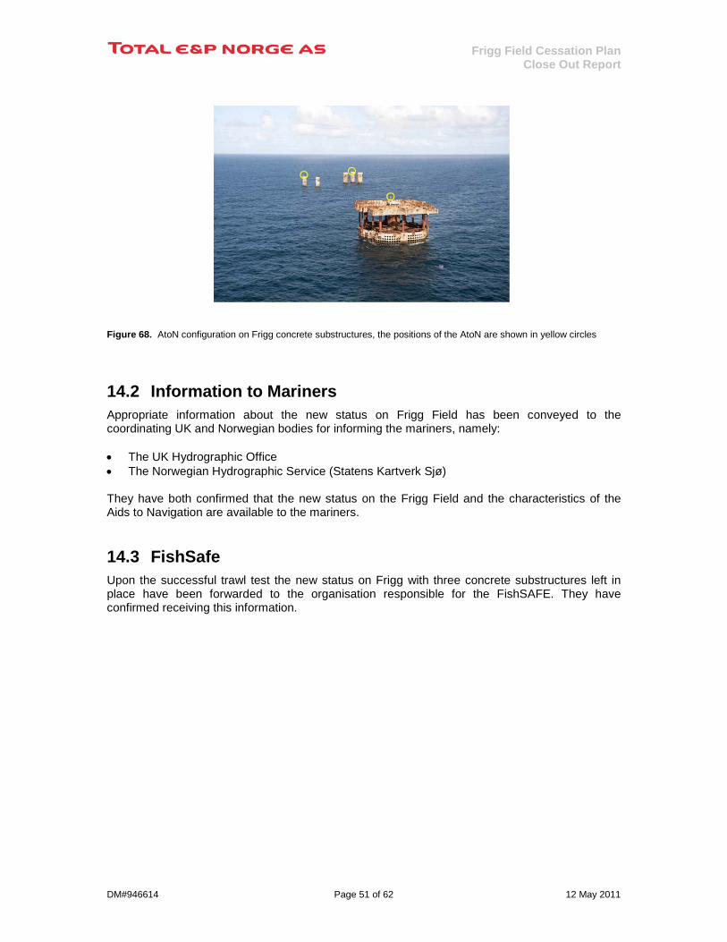
Frigg Field Cessation Plan Close Out Report
DM#946614 Page 51 of 62 12 May 2011
Figure 68. AtoN configuration on Frigg concrete substructures, the positions of the AtoN are shown in yellow circles
14.2 Information to Mariners Appropriate information about the new status on Frigg Field has been conveyed to the coordinating UK and Norwegian bodies for informing the mariners, namely: • The UK Hydrographic Office • The Norwegian Hydrographic Service (Statens Kartverk Sjø) They have both confirmed that the new status on the Frigg Field and the characteristics of the Aids to Navigation are available to the mariners.
14.3 FishSafe Upon the successful trawl test the new status on Frigg with three concrete substructures left in place have been forwarded to the organisation responsible for the FishSAFE. They have confirmed receiving this information.

Frigg Field Cessation Plan Close Out Report
DM#946614 Page 52 of 62 12 May 2011
15 Recommended Mitigating Measures in the EIA The independent Environmental Impact Assessment (EIA) in the Frigg Field Cessation Plan [1] performed by Det Norske Veritas (DNV) identified a number of mitigating measures which they recommended should be addressed during the decommissioning works. Table 20 concludes that all the measures recommended have been fulfilled.
Mitigating Measure Suggested by DNV [1] Status after completing the Cessation Plan
Clean-up of seabed debris to eliminate the risk of damage to fishing gear and reduce the potential for littering. This should be planned as a three stage process – identification, removal and verification
All these activities have been completed. Identification: Ref. Section 11 Removal: Ref. Section 11 Verification: Ref. Section 13
Install navigation lights on the installations left in place to prevent the occurrence of dangerous situations with passing vessels
Navigation aids have been installed on the three concrete substructures; built and installed in accordance to UK and Norwegian regulations. These aids are monitored on a daily basis via satellite. Ref. Section 14
Removal of external steelwork on the concrete substructures left in place, to limit the obstruction and risks to fisheries.
All steelwork on the outside of the concrete substructures have been removed as far as reasonably practicable. TCP2: Ref. Section 5.3.2 TP1: Ref. Section 6.2.2
Cover cut ends of the steel substructure foundation piles to avoid damage to fishing gear.
The dredged areas around the foundation piles of the removed steel jackets have been cover by gravel. Ref. Sections 5.1.3, 5.2.2 and 6.1.3
Select favourable time of year, favourable weather conditions and protect and scare fish away to limit impacts if using explosives to obtain the –55m clearance for the partial removal alternative for CDP1. Develop guidelines for observation for cetaceans to be incorporated in the execution plan.
The concrete substructure CDP1 has received a permit to be left in place at its present position.
Remove all pipelines within the safety zone, including export pipelines not being part of this EIA, to ensure access for fisheries without any possible obstacles on the seabed
All infield pipelines and cables between the Frigg platforms have been removed and brought to shore for disposal. Ref. Sections 5.4 and 6.4 Other sealines within 500m of the installations have been removed up to the point they are buried. The disused sections of the two 32” export pipelines and the 24” pipeline from Alwyn are not removed. The decommissioning of these disused pipeline sections will be addressed when the complete pipeline systems are decommissioned. (It should be noted that all these sealines are not included within the scope of the Frigg Field Cessation Plan).
Comply with the implemented EMAS system to ensure that continuous improvement and openness are key parts of the planning and execution of all work associated with the decommissioning of the Frigg Field facilities.
The EMAS system was used to achieve the defined objectives.
Steel items covered with polyurethane paint should be identified before the start of demolition. Cutting with thermal means will cause the release of isocyanates, which could cause serious harmful effects in humans.
A procedure was put in place when applying hot cutting on painted surfaces offshore and onshore to prevent personnel being exposed to isocyanates. Ref. Section 8.2.1
Sound material and waste management with optimal reuse/recycling is considered very important, and a stretched target for reuse/recycle should be considered. A dedicated waste handling module capable of tracking all waste fractions has been developed to be included in the environmental accountancy system.
A comprehensive material and waste management procedures have been implemented named TEAMS. Ref. Sections 7 and 9.
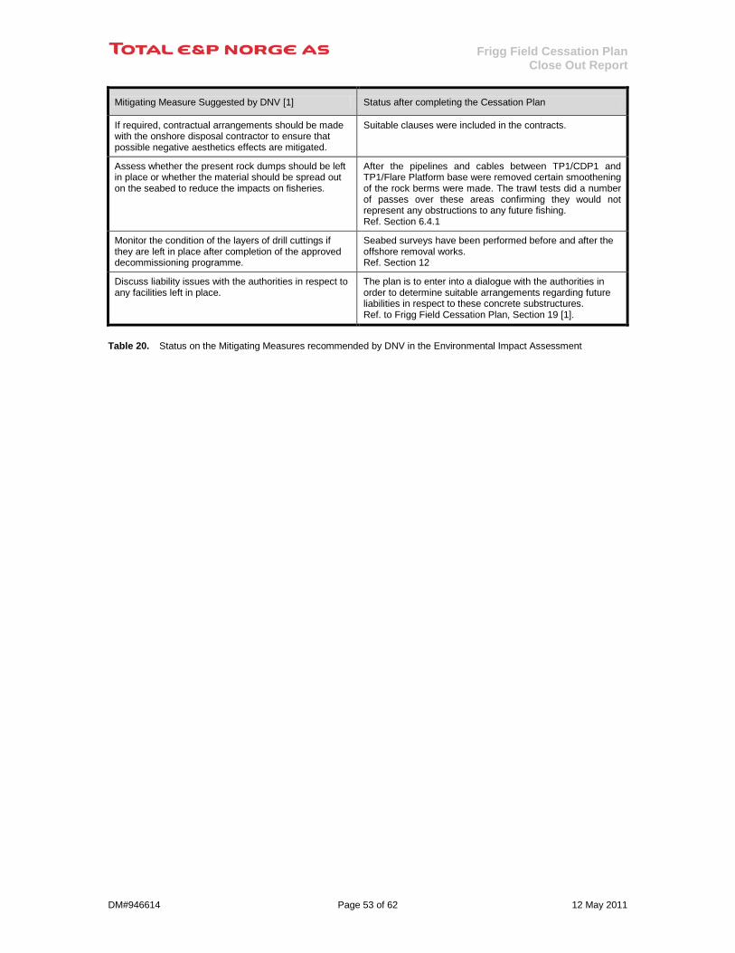
Frigg Field Cessation Plan Close Out Report
DM#946614 Page 53 of 62 12 May 2011
Mitigating Measure Suggested by DNV [1] Status after completing the Cessation Plan
If required, contractual arrangements should be made with the onshore disposal contractor to ensure that possible negative aesthetics effects are mitigated.
Suitable clauses were included in the contracts.
Assess whether the present rock dumps should be left in place or whether the material should be spread out on the seabed to reduce the impacts on fisheries.
After the pipelines and cables between TP1/CDP1 and TP1/Flare Platform base were removed certain smoothening of the rock berms were made. The trawl tests did a number of passes over these areas confirming they would not represent any obstructions to any future fishing. Ref. Section 6.4.1
Monitor the condition of the layers of drill cuttings if they are left in place after completion of the approved decommissioning programme.
Seabed surveys have been performed before and after the offshore removal works. Ref. Section 12
Discuss liability issues with the authorities in respect to any facilities left in place.
The plan is to enter into a dialogue with the authorities in order to determine suitable arrangements regarding future liabilities in respect to these concrete substructures. Ref. to Frigg Field Cessation Plan, Section 19 [1].
Table 20. Status on the Mitigating Measures recommended by DNV in the Environmental Impact Assessment
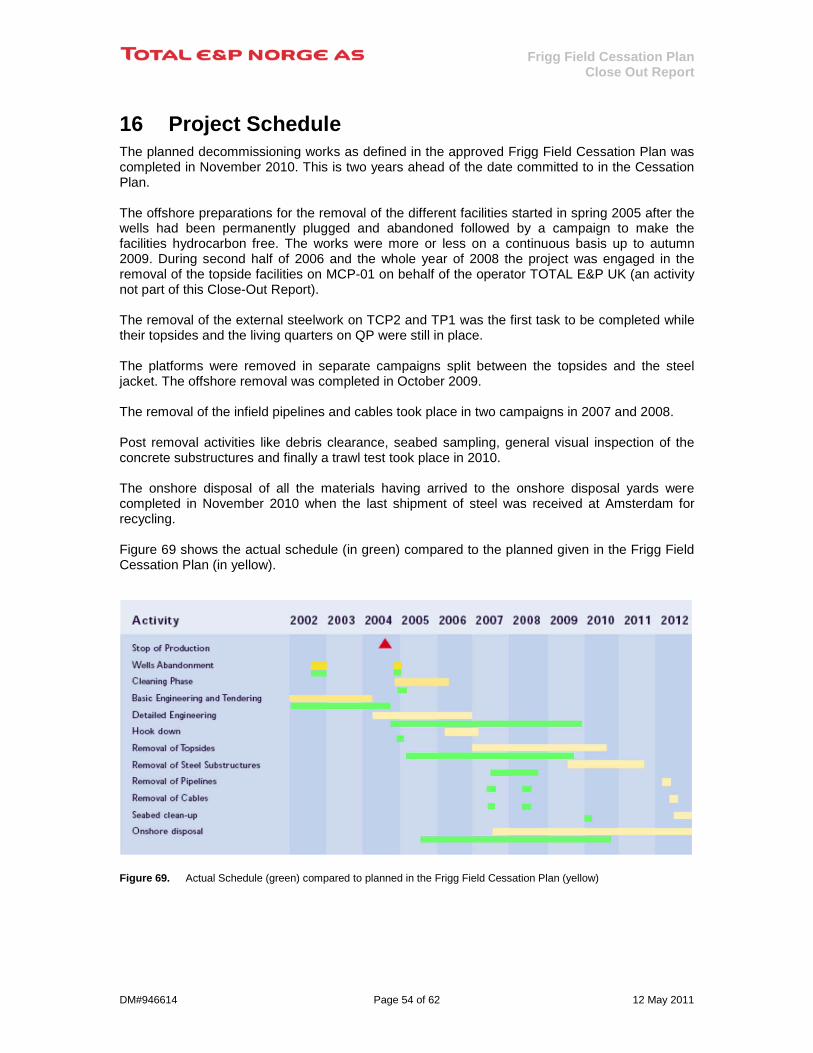
Frigg Field Cessation Plan Close Out Report
DM#946614 Page 54 of 62 12 May 2011
16 Project Schedule The planned decommissioning works as defined in the approved Frigg Field Cessation Plan was completed in November 2010. This is two years ahead of the date committed to in the Cessation Plan. The offshore preparations for the removal of the different facilities started in spring 2005 after the wells had been permanently plugged and abandoned followed by a campaign to make the facilities hydrocarbon free. The works were more or less on a continuous basis up to autumn 2009. During second half of 2006 and the whole year of 2008 the project was engaged in the removal of the topside facilities on MCP-01 on behalf of the operator TOTAL E&P UK (an activity not part of this Close-Out Report). The removal of the external steelwork on TCP2 and TP1 was the first task to be completed while their topsides and the living quarters on QP were still in place. The platforms were removed in separate campaigns split between the topsides and the steel jacket. The offshore removal was completed in October 2009. The removal of the infield pipelines and cables took place in two campaigns in 2007 and 2008. Post removal activities like debris clearance, seabed sampling, general visual inspection of the concrete substructures and finally a trawl test took place in 2010. The onshore disposal of all the materials having arrived to the onshore disposal yards were completed in November 2010 when the last shipment of steel was received at Amsterdam for recycling. Figure 69 shows the actual schedule (in green) compared to the planned given in the Frigg Field Cessation Plan (in yellow).
Figure 69. Actual Schedule (green) compared to planned in the Frigg Field Cessation Plan (yellow)

Frigg Field Cessation Plan Close Out Report
DM#946614 Page 55 of 62 12 May 2011
The completion dates for the offshore removal of the Frigg facilities are shown in Table 21:
Facility Completion Drilling and Production Platform 2 - DP2 Topsides September 2007 Jacket July 2008 Quarters Platform - QP Topsides May 2008 Jacket August 2009 Wreck of Drilling Platform 1 - DP1 Jacket October 2009 Treatment and Compression Platform 2 - TCP2 External Steelwork May 2005 Topsides July 2007 Treatment Platform 1 - TP1 External Steelwork July 2006 Topsides July 2009 Concrete Drilling Platform 1 - CDP1 Topsides May 2009 Pipelines and cables August 2008
Table 21. Offshore completion date for the Frigg Field facilities

Frigg Field Cessation Plan Close Out Report
DM#946614 Page 56 of 62 12 May 2011
17 Cost Summary The cost figures are presented in the same manner as given in the approved Frigg Field Cessation Plan dated 9 May 2003 [1]. The cost estimates in the Cessation Plan was established in 2002 based on certain assumptions on removal methods as described in the Plan. In 2004 the Cessation Budget for the project was consolidated based on the main contract for offshore removal and onshore disposal awarded in October 2004. The costs given in Table 22 and Table 23 do not include the plugging and abandonment of the wells on DP2 and CDP1.
17.1 Cost for Removal and Disposal of the Norwegian Facilities Table 22 gives the cost summary for the removal and disposal of the Norwegian facilities on the Frigg Field.
Cessation Plan ‘02 MNOK in 2002 value
Cessation Plan ‘02 MNOK in 2010 value
Cessation Budget ‘04 MNOK in 2010 value
Final Cost MNOK in 2010 value
Platform TCP2 725 849 1 283 1 428
Platform DP2 697 817 897 1 104
DP1 Wreck 330 387 699 575
Pipelines & cables 64 75 151 119
Seabed clean up 36 42 49 61
Sum 1 852 2 170 3 080 3 287
Table 22. Cost summary for the Norwegian facilities on the Frigg Field Compared to the Cessation Budget the final project cost for the Norwegian facilities on the Frigg Field represents a cost increase of 6.7%. The main reason for this increase can be attributed to the extended preparation/hook-down period needed to make the installations ready for removal, mainly due to a more complex operation than originally foreseen. This in turn, resulted in increased requirements for flotel and other support vessels, as well as logistics means and general support both offshore and onshore.
17.2 Cost for Removal and Disposal of the UK Facilities The cost for the UK facilities in the Cessation Plan established in 2002 was presented in £ based on an exchange rate of 13.08 NOK/£. In the Table 23 this exchange rate has been kept to give a relevant comparison with the final cost. Table 23 gives the cost summary for the removal and disposal of the UK facilities on the Frigg Field.

Frigg Field Cessation Plan Close Out Report
DM#946614 Page 57 of 62 12 May 2011
Cessation Plan 2002
In 2002 value Cessation Plan 2002
In 2010 value Cessation Budget 2004
In 2010 value Final Cost In 2010 value
Platform QP 551 MNOK / £42.1m 646 MNOK / £49.4m 762 MNOK / £58.3m 1 007 MNOK / £77.0m
Platform TP1 358 MNOK / £27.4m 419 MNOK / £32.0m 589 MNOK / £45.0m 846 MNOK / £64.7m
Platform CDP1 593 MNOK / £45.3m 695 MNOK / £53.2m 629 MNOK / £48.1m 629 MNOK / £48.1m
Pipelines & cables 97 MNOK / £7.4m 114 MNOK / £8.7m 225 MNOK / £17.2m 178 MNOK / £13.6m
Seabed clean up 32 MNOK / £2.5m 37 MNOK / £2.8m 40 MNOK / £3.1m 49 MNOK/£3.8m
Sum 1 631MNOK / £124.7m 1 911 MNOK / £146.1m 2 246MNOK / £171.7m 2 710MNOK / £207.2m
Table 23. Cost summary for the UK facilities on the Frigg Field
The exchange rate used is 13.08 NOK/£ as applied initially when establishing the Frigg Field Cessation Plan in 2002.
Compared to the Cessation Budget the final project cost for the UK facilities on the Frigg Field represent a cost increase of 20.7%. The main reason for this increase can be attributed to the extended preparation/hook-down period needed to make the installations ready for removal, mainly due to a more complex operation than originally foreseen, but also due to change in removal method at a late stage in the process for QP jacket and CDP1 topside. This in turn, resulted in increased requirements for flotel and other support vessels, as well as logistics means and general support both offshore and onshore.
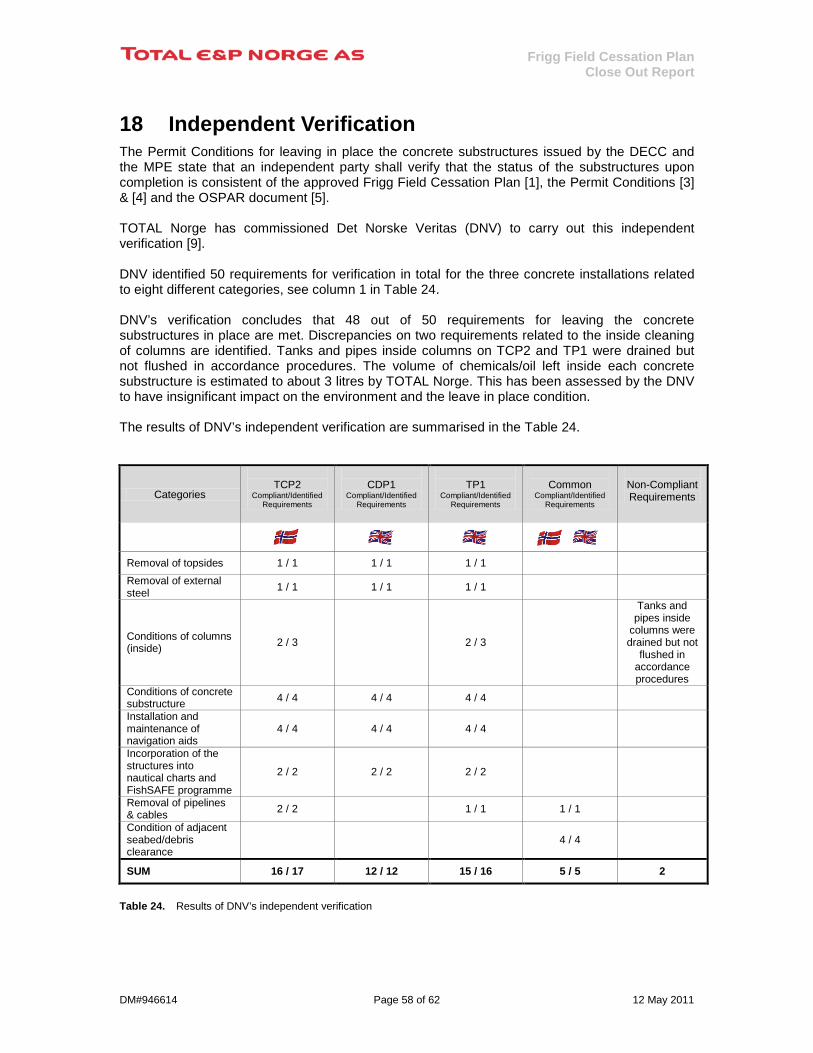
Frigg Field Cessation Plan Close Out Report
DM#946614 Page 58 of 62 12 May 2011
18 Independent Verification The Permit Conditions for leaving in place the concrete substructures issued by the DECC and the MPE state that an independent party shall verify that the status of the substructures upon completion is consistent of the approved Frigg Field Cessation Plan [1], the Permit Conditions [3] & [4] and the OSPAR document [5]. TOTAL Norge has commissioned Det Norske Veritas (DNV) to carry out this independent verification [9]. DNV identified 50 requirements for verification in total for the three concrete installations related to eight different categories, see column 1 in Table 24. DNV’s verification concludes that 48 out of 50 requirements for leaving the concrete substructures in place are met. Discrepancies on two requirements related to the inside cleaning of columns are identified. Tanks and pipes inside columns on TCP2 and TP1 were drained but not flushed in accordance procedures. The volume of chemicals/oil left inside each concrete substructure is estimated to about 3 litres by TOTAL Norge. This has been assessed by the DNV to have insignificant impact on the environment and the leave in place condition. The results of DNV’s independent verification are summarised in the Table 24. TCP2
Categories
TCP2
Compliant/Identified Requirements
CDP1
Compliant/Identified Requirements
TP1
Compliant/Identified Requirements
Common
Compliant/Identified Requirements
Non-Compliant Requirements
Removal of topsides 1 / 1 1 / 1 1 / 1 Removal of external steel 1 / 1 1 / 1 1 / 1
Conditions of columns (inside) 2 / 3 2 / 3
Tanks and pipes inside
columns were drained but not
flushed in accordance procedures
Conditions of concrete substructure 4 / 4 4 / 4 4 / 4
Installation and maintenance of navigation aids
4 / 4 4 / 4 4 / 4
Incorporation of the structures into nautical charts and FishSAFE programme
2 / 2 2 / 2 2 / 2
Removal of pipelines & cables 2 / 2 1 / 1 1 / 1
Condition of adjacent seabed/debris clearance
4 / 4
SUM 16 / 17 12 / 12 15 / 16 5 / 5 2
Table 24. Results of DNV’s independent verification

Frigg Field Cessation Plan Close Out Report
DM#946614 Page 59 of 62 12 May 2011
19 Feedback on Structural Performance The removal of the jacket steel structures offered an excellent opportunity to learn about their structural performance after being exposed to environmental loads over for more than 30 years. This would represent a valuable feedback to life-time extension studies of existing structures as well as input to the design of new offshore structures. A number of representative nodes have therefore been cut from the DP2, QP and DP1 steel jackets at different locations and sent to a laboratory for detailed inspection to check their structural response, see Figure 70.
Figure 70. Part of nodes cut out from the DP1, DP1 and QP jackets ready to be sent to the laboratory
No results were available at the time this report was concluded.

Frigg Field Cessation Plan Close Out Report
DM#946614 Page 60 of 62 12 May 2011
20 References 1. Approved Frigg Field Cessation Plan, dated 9 May 2003 2. Letter dated 01.10.2003 from the Norwegian Ministry of Petroleum and Energy to TOTAL
E&P NORGE AS: "Disponering av innretningene på Frigg-feltet", (incl.Kongelig Resolusjon: Godkjennelse av avslutningsplan for Frigg-feltet);
(Approval of Frigg Field Cessation Plan except for the concrete substructure TCP2, which is addressed under [4]).
3. Letter dated 18.11 2003 from the UK Department of Trade and Industry to TOTAL E&P
NORGE AS: "Petroleum Act 1998 Abandonment of the Frigg Field Facilities", (incl. "Petroleum Act 1998 Section 32(1) Approval of a programme for Abandonment" and "Permit to leave in place the concrete substructures of the Frigg TP1 and CDP1 installations in accordance with OSPAR decision 98/3")
4. Letter dated 23.04.2004 from the Norwegian Ministry of Petroleum and Energy to TOTAL
E&P NORGE AS: "Tillatelse til etterlatelse av betongunderstellet TCP2 på Frigg-feltet"; (“Approval to leave in place the concrete substructure TCP2 on the Frigg Field”).
5. The OSPAR consultation document “An Assessment of Proposals for the Disposal of the
Concrete Substructures of Disused Frigg Field Installations TCP2, CDP1 and TP1”, dated 6 August 2002
6. Debris recovery at Frigg/MCP-01-Final report, GEN-AKOPS-Z-0065, rev. 02,
dated 19.05.2010 7. DNV Report Environmental Sediment Survey Frigg 2010, Report No./DNV Reg No.: 2010-
1479/ 12O31ER-5, Rev 01, 2010-11-30 8. Evaluation of the Frigg field environmental sediment status at the end of the
decommissioning program, TOTAL E&P NORGE AS report, dated 22.12.2010, Dm #948700 9. Verification of the Frigg Field Disposal Arrangements – Final Report, Report No./DNV ref
No.: 2011-0345 / 12QFK9T-4, Rev 1.0, dated 16.03.2011

Frigg Field Cessation Plan Close Out Report
DM#946614 Page 61 of 62 12 May 2011
Appendix 1
Clear Seabed Certificates
Table 25. Certificate from Trawl Test performed in September 2008
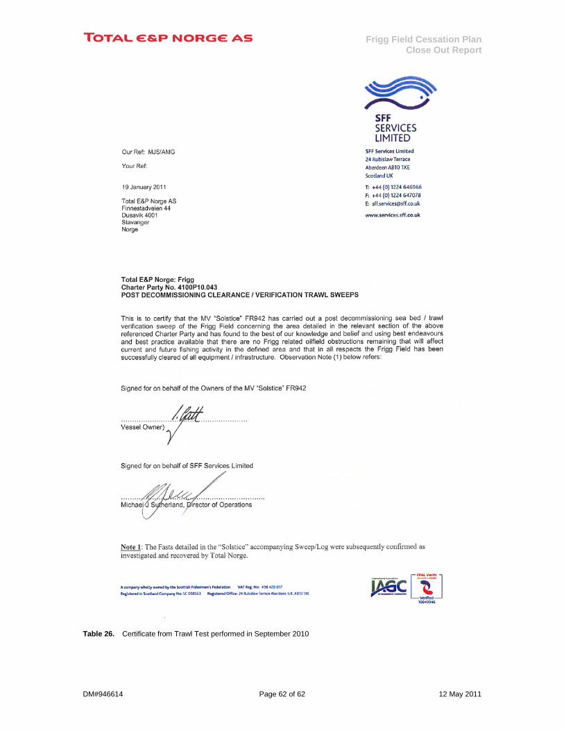
Frigg Field Cessation Plan Close Out Report
DM#946614 Page 62 of 62 12 May 2011
Table 26. Certificate from Trawl Test performed in September 2010