frm220-ccf40 user guide - future ready solutions
TRANSCRIPT


CTC Union Technologies Co., Ltd. Far Eastern Vienna Technology Center
(Neihu Technology Park)
8F, No. 60, Zhouzi St., Neihu, Taipei 114,
Taiwan
T +886-2-26591021
F +886-2-26590237
H www.ctcu.com
© 2017 CTC Union Technologies Co., LTD. All trademarks are the property of their respective owners.
Technical information in this document is subject to change without notice.

w w w . C T C U . c o m
User Guide FRM220-CCF40
4-Channel Contact Closure Media Converters
Table of Contents
Version 1.0 August, 2017
Introduction ------- 1
Features/Specifications ------- 2
Panel ------- 3
Installation/SFP ------- 4
LED Indicators ------- 5
Console Management ------- 6
Main Menu Operation ------- 7
Channel Information and Configuration ------- 8
Fiber Information and Configuration ------- 9
Device Information and Configuration ------- 10
Upgrading ------- 11
Application ------- 14

- 1 - w w w . C T C U . c o m
Introduction
FRM220-CCF40 models are 4-channel contact closure fiber converters that can provide transmission of contact closure via fiber optic link. With SFP socket, FRM220-CCF40 provides SFP-LC connector that enables multi-mode, single-mode or bi-directional transmission using only a single fiber cable.
The contact closure module has four relay inputs and outputs. Outputs
are normally open relays. The relay output follows the relay inputs at the remote end. When the remote relay input is shorted, the local relay output is closed. The front panel provides LED indicators that offer real-time information of input and output status. Applications include alarm event triggering, building automation, environmental control systems, fire & alarm systems, gate control, traffic signal control equipment, and more.
WARNING: Fiber optic equipment may emit laser or infrared light that can injure your eyes. Never look into an optical fiber or connector port. Always assume that fiber optic cables are connected to a laser light source.
Management Features
FRM220-CCF40 has an embedded processor which can be used to configure the device for stand-alone operation. When placed in a stand-alone chassis with DB9 console port, these devices support a text based serial terminal with an easy to use menu system for configuration. When placed in a managed chassis, the card is configured and monitored through the chassis NMC (network management controller) via local console or remote Telnet, Web HTTP or SNMP.
1. Stand-alone - with serial console, menu driven
2. Rack management - When placed in NMC managed rack, all other
settings are overridden by the NMC management.
- 2 - w w w . C T C U . c o m
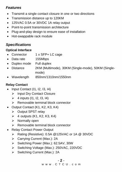
Features
Transmit a single contact closure in one or two directions
Transmission distance up to 120KM
125VAC 0.5A or 30VDC 1A relay output
Point-to-point transmission architecture
Plug-and-play design to ensure ease of installation
Hot-swappable rack module
Specifications
Optical Interface
Connector 1 x SFP+ LC cage
Data rate 155Mbps
Duplex mode Full duplex
Distance 2KM (Multimode), 30KM (Single-mode), 50KM (Single-
mode)
Wavelength 850nm/1310nm/1550nm
Relay Contact
Input Contact (I1, I2, I3, I4)
Input Dry Contact Closure
4 inputs (I1, I2, I3, I4)
Removable terminal block connector
Output Contact (K1, K2, K3, K4)
Output SPST relay
4 outputs (K1, K2, K3, K4)
Normally open
Removable terminal block connector
Relay Contact Power Output
Rating (Resistive): 0.5A @125VAC or 1A @ 30VDC
Carrying Current (Max.): 2A
Switching Power (Max.): 62.5AV, 30W
Switching Voltage (Max.): 250VAC, 220VDC
Switching Current (Max.): 2A

- 3 - w w w . C T C U . c o m
Power Operating Voltage: 8~15VDC Support power input reverse polarity protection Consumption: 4W (Max.)
Mechanical Dimensions: 155mm (D) x 208mm (W) x 88mm (H) Weight: 200 g
Environment Operating Temperature: 0°C~50°C Storage Temperature: -10°C~85°C Humidity: 5%~95% (non-condensing) MTBF: >100,000 Hours
Panel
No. Description
1 Thumb screw
2 SFP slot
3 Power, System, Link, Test/Alarm LED indicators
4 Removable terminal block for input contacts, COM and output contacts
5 Input contacts (I1, I2, I3, I4), COM, output contacts (K1, K2, K3, K4) LED indicators
Panel Index Reference
5 4
3
2
1
- 4 - w w w . C T C U . c o m
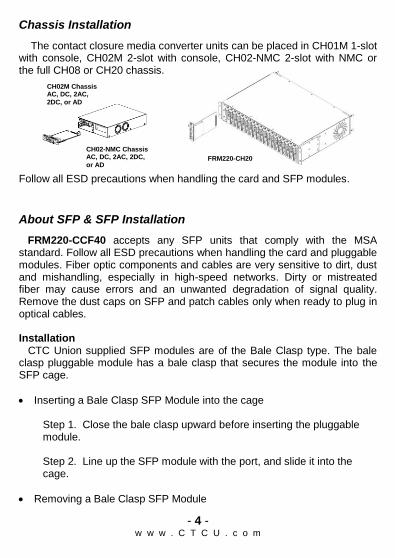
Chassis Installation
The contact closure media converter units can be placed in CH01M 1-slot with console, CH02M 2-slot with console, CH02-NMC 2-slot with NMC or the full CH08 or CH20 chassis.
Follow all ESD precautions when handling the card and SFP modules.
About SFP & SFP Installation
FRM220-CCF40 accepts any SFP units that comply with the MSA standard. Follow all ESD precautions when handling the card and pluggable modules. Fiber optic components and cables are very sensitive to dirt, dust and mishandling, especially in high-speed networks. Dirty or mistreated fiber may cause errors and an unwanted degradation of signal quality. Remove the dust caps on SFP and patch cables only when ready to plug in optical cables. Installation CTC Union supplied SFP modules are of the Bale Clasp type. The bale clasp pluggable module has a bale clasp that secures the module into the SFP cage.
Inserting a Bale Clasp SFP Module into the cage
Step 1. Close the bale clasp upward before inserting the pluggable module. Step 2. Line up the SFP module with the port, and slide it into the cage.
Removing a Bale Clasp SFP Module
CH02-NMC Chassis AC, DC, 2AC, 2DC,
or AD FRM220-CH20
CH02M Chassis AC, DC, 2AC,
2DC, or AD

- 5 - w w w . C T C U . c o m
Step 1. Open the bale clasp on the SFP module. Press the clasp downward with your index finger. Step 2. Grasp the SFP module between your thumb and index finger and carefully remove it from the SFP cage.
Bale Clasp type SFP with bale open
LED Indicators
LED Color State Descriptions
PWR Green
On Power on
Off No power
Flash
1. Upgrade firmware (On/Off 100ms)
2. Device is in disable mode (On: 1 second, Off: 4 seconds)
System Green On Normal
Off System errors
Link Green
On Link up and sync
Flash Link up but sync loss (On/Off 100ms)
Off Loss of signal
Alarm/ Test
Red
On Link down, sync loss or power error
Off Normal
Flash Local loopback test or loopback detected (On/Off 100ms)
CH1~4 Input (I1, I2, I3, I4)
Green On Active
Off Not active
CH1~4 Output (K1, K2, K3, K4)
Green On Active
Off Not active

- 6 - w w w . C T C U . c o m
Console Management
When placed in the chassis, this card can be locally managed by connecting a simple serial terminal such as a notebook computer that has an RS232 port or via a commonly available USB to RS232 adapter. In Windows® XP, HyperTerminal™ is an application available for emulating a serial terminal. You can also search for TeraTerm or PuTTY which are free alternatives, especially if your operating system is Vista or Win7. Settings: Baud Rate: 38,400 Data bits: 8 Parity bits: none Stop bits: 1 Handshaking: none Emulation: VT-100 Default username/password: admin/admin
Connect the serial cable to the chassis' DB9. Run the terminal emulation program. About 3 seconds after being powered on, the FRM220-CCF40 will display the login menu as shown in the following example.
Example of Login Menu Console Screen
NOTE: All settings done by console menu are ignored if the card is placed in the chassis (such as FRM220-CH20) with NMC/SNMP management. The card will follow the settings done via the chassis management. (Refer to NMC Operation Manual for details on managing all cards.)
*****************************************
*** CTC UNION TECHNOLOGIES CO.,LTD. ***
*** FRM220-CCF40 Manager ***
*****************************************
Ver:[1.000-1.000-0.010-0.000] [CH-01M ]
Username : admin
Password :

- 7 - w w w . C T C U . c o m
Main Menu Operation
Select any of the menu items by keying in the menu item number or letter. Use the [ESC] key to Logout. Any setting is immediately applied to the converter's circuitry. After all of the parameter settings have been selected, go to the Main menu page and press "S" to store the settings in non-volatile RAM (NVR). <1> Channel Information And Configuration: Enter this menu to view the Input and Output status for Channel 1~4. Users can also set up how relay is controlled in this configuration page. <2> Fiber Port Information And Configuration: Enter this menu to view status of SFP slot and view DD information of the inserted SFP. Users can also set up "Port Active", enable or disable "Loopback" and "ALS" function in this menu. <3> Device Information And Configuration: Enter this menu to enable/disable the device, reset the device, set the device to factory default settings and enable/disable "Input Debounce" function. <U> Update with X-Modem: Update firmware via X-Modem. <S> Store Parameters: Saves the setting parameters into non-volatile RAM (NVR). <P> Password Setup: Enter this menu to change the login password. The old password must be keyed in followed by the new password twice. If the password is ever forgotten, please contact customer support for details on resetting the password.
*****************************************
*** CTC UNION TECHNOLOGIES CO.,LTD. ***
*** FRM220-CCF40 Manager ***
*****************************************
Ver:[1.000-1.000-0.010-0.000] [CH-01M ]
< 1 > Channel Information And Configuration
< 2 > Fiber Port Information And Configuration
< 3 > Device Information And Configuration
< U > Update With X-Modem
< S > Store Parameters
< P > Password Setup
[ ESC ] Logout

- 8 - w w w . C T C U . c o m
Channel Information And Configuration The table displayed in the upper part of the screen shows the current status of channel 1~4 Input & Output. Once the status of channel 1~4 has been changed, real-time status information will be shown here. <1> Channel 01: Select 1 to set up how relay of Channel 01 is controlled. Three methods are provided. One is "By Input" which means the relay is triggered by actual input signals. "Force On" is to put the Channel 01 in shorted state no matter whether there is actual input or not. "Force Off" is to turn off the channel 01. <2> Channel 02: Select 2 to set up how relay of Channel 02 is controlled. Three methods are provided. One is "By Input" which means the relay is triggered by actual input signals. "Force On" is to put the Channel 02 in shorted state no matter whether there is actual input or not. "Force Off" is to turn off the channel 02. <3> Channel 03: Select 3 to set up how relay of Channel 03 is controlled. Three methods are provided. One is "By Input" which means the relay is triggered by actual input signals. "Force On" is to put the Channel 03 in shorted state no matter whether there is actual input or not. "Force Off" is to turn off the channel 03. <4> Channel 04: Select 4 to set up how relay of Channel 04 is controlled. Three methods are provided. One is "By Input" which means the relay is triggered by actual input signals. "Force On" is to put the Channel 04 in shorted state no matter whether there is actual input or not. "Force Off" is to turn off the channel 04.
<< Channel 1 ~ 4 Information And Configuration >>
+----+------------+------------+ +----+------------+------------+
| CH | Input (DI) | Output (K) | | CH | Input (DI) | Output (K) |
+----+------------+------------+ +----+------------+------------+
| 1 | Active | Non Active | | 3 | Active | Non Active |
| 2 | Active | Non Active | | 4 | Active | Non Active |
+----+------------+------------+ +----+------------+------------+
< Configuration > Relay Control
<1> Channel 01 [By Input ] <3> Channel 03 [By Input ]
<2> Channel 02 [By Input ] <4> Channel 04 [By Input ]
[ESC] Go to previous menu.
- 9 - w w w . C T C U . c o m
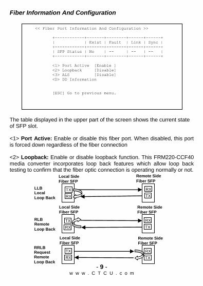
Fiber Information And Configuration
The table displayed in the upper part of the screen shows the current state of SFP slot. <1> Port Active: Enable or disable this fiber port. When disabled, this port is forced down regardless of the fiber connection <2> Loopback: Enable or disable loopback function. This FRM220-CCF40 media converter incorporates loop back features which allow loop back testing to confirm that the fiber optic connection is operating normally or not.
<< Fiber Port Information And Configuration >>
+------------+-------+--------+------+------+
| | Exist | Fault | Link | Sync |
+------------+-------+--------+------+------+
| SFP Status | No | -- | -- | -- |
+------------+-------+--------+------+------+
<1> Port Active [Enable ]
<2> Loopback [Disable]
<3> ALS [Disable]
<D> DD Information
[ESC] Go to previous menu.
LLB Local
Loop Back
Remote Side
Fiber SFP Local Side
Fiber SFP
TX
RX
RX
TX
Remote Side
Fiber SFP
Local Side
Fiber SFP
RLB Remote
Loop Back
TX
RX
RX
TX
Remote Side
Fiber SFP
Local Side
Fiber SFP RRLB Request Remote
Loop Back
TX
RX
RX
TX

- 10 - w w w . C T C U . c o m
<2> ALS: Enable or disable ALS function. Automatic Laser Shutdown (ALS) is a technique used to automatically shut down the output power of the transmitter in case of fiber break according to ITU-T G.664. This is a safety feature that prevents dangerous levels of laser light from leaking out of a broken fiber, provided ALS is provisioned on both ends of the fiber pair. The sequence of events is as follows. If a fiber is cut, the receiver will detect a Loss Of Signal (LOS). The ALS agent will turn off the transmitter. The receiver at the far end will then detect an LOS and its ALS agent will turn off the transmitter. In this way the entire fiber will go dark. <D>DD Information: View digital diagnostics information of the inserted SFP transceiver.
Device Information And Configuration
<< Device Information And Configuration >>
Alarm: [LOS]
<1> Device Active [Enable ]
<2> Device Reset
<3> Device Default
<4> Input Debounce [Disable]
[ESC] Go to previous menu.
*****************************************
*** CTC UNION TECHNOLOGIES CO.,LTD. ***
*** FRM220-CCF40 Manager ***
*****************************************
Ver:[1.000-1.000-0.010-0.000] [CH-01M ]
<< SFP+ Digital Diagnostics >>
Vendor Name [CTC UNION ]
Vendor Number [SFS-7010-L31(I) ]
Fiber Type [Single Mode ]
Tx Wave Length [1310 nm ]
Rx Wave Length [1310 nm ]
Link Length [0010 Km ]
[ESC] Go to previous menu.

- 11 - w w w . C T C U . c o m
<1> Device Active: Enable or disable the device. When disabled, all LED indicators will be turned off except the power LED indicator. <2> Device Reset: This will cause the soft reboot of the device and parameters settings in NVR to be reloaded. <3> Factory Default: Restores all settings to factory default. The save operation must still be performed. <4> Input Debounce: When enabled, the device can stabilize bouncing situations when power signals are rising and falling constantly.
Upgrading
Stand-alone Firmware Upgrading via Xmodem
The FRM220-CCF40 card may be firmware upgraded using XMODEM when placed in the chassis such as CH02M. The user may use serial terminal such as a notebook computer that has an RS232 port or via a commonly available USB to RS232 adapter. Then, use a serial terminal that can support XMODEM such as TeraTerm to start Firmware upgrade process. Quick Procedure 1. In the Main Menu, Key in “U” to enter Firmware upgrade page. Then,
Key in “1” to start uploading Firmware.

- 12 - w w w . C T C U . c o m
2. Select "Y" and then send Firmware file via Xmodem and select the Firmware file that you want to upload.
3. Start upgrading new Firmware image. 4. Check the Firmware version after completing the Firmware upgrade
process.

- 13 - w w w . C T C U . c o m
Firmware Upgrading via NMC Card
The FRM220-CCF40 card may be firmware upgraded when it is placed in the FRM220 with NMC management card. The user may use a local console connection to the NMC, a remote Telnet (IP) connection, or a Web based (HTTP) connection with any available browser. The NMC communicates to all cards through a serial TTL control bus. The upgrade code is transferred to the NMC by way of TFTP server. Quick Procedure Place the line card's upgrade code on the TFTP server. Make sure you know the case sensitive file name. Connect to the FRM220-NMC by local console or by remote Telnet connection. From the main menu choose: <L> SNMP System Configuration Setup
Then: <U> Upgrade Line Card Menu
Select the line card type (FRM220-CCF40) and local unit. Enter filename. The upgrade should complete in only a couple of minutes. DO NOT disconnect or pullout/insert any other cards during the upgrade process.
****************************************
*** CTC UNION TECHNOLOGIES CO., LTD. ***
*** FRM220 NMC VER. 3.45 ***
****************************************
<< Upgrade Line Card Menu >>
Target IP : 59.125.162.252
Target Gateway : 59.125.162.241
TFTP Server IP : 59.125.162.243
Please select a card type:
<1> : FRM220-10/100I and FMC-10/100I <3> : FRM220-SERIAL
<2> : FRM220-FXO/FXS <4> : FRM220-155MS
<5> : FRM220-DATAPORT <6> : FRM220-E1/T1
<7> : FRM220-1000EDS/1000ES-2F <8> : FRM220-1000ES-1/1000E-1/2F
<9> : FRM220-10/100IS-2 <A> : FRM220-1000TS/1000T
<B> : FRM220-3R-2.7G-2S/3S <C> : FRM220-5E1/ET100T
<D> : FRM220-5E1/ET100S <E> : FRM220-Eoe1
<F> : FRM220-3R-10G/SS/SX/XX <G> : FRM220-3R-10G/SS/SX/XX CDR
%< Snip ...
<X> : FRM220-16E1/ET100T <Y> : FRM220-16E1/ET100S
<Z> : FRM220-CCF40
<ESC>: Previous Menu
- 14 - w w w . C T C U . c o m
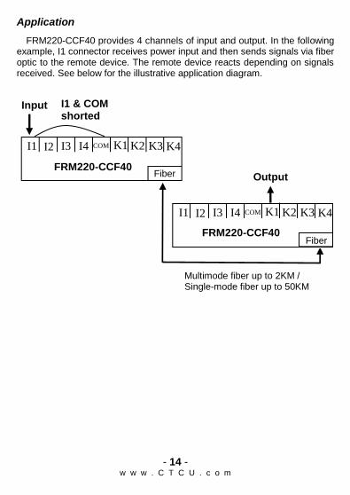
Application
FRM220-CCF40 provides 4 channels of input and output. In the following example, I1 connector receives power input and then sends signals via fiber optic to the remote device. The remote device reacts depending on signals received. See below for the illustrative application diagram.
Multimode fiber up to 2KM / Single-mode fiber up to 50KM
FRM220-CCF40
FRM220-CCF40
Output
I1 & COM shorted
Fiber
K1 K2 COM K3 K4 I2 I1 I3 I4
Input
K1 K2 COM K3 K4 I2 I1 I3 I4
Fiber