from domain descriptions to requirement prescriptionsdibj/2016/uppsala/req-slides.pdf · 1 from...
TRANSCRIPT

1
From Domain Descriptions to Requirement Prescriptions
A Different Approach to Requirements Engineering
Dines Bjørner
Uppsala, 18–20 May, 2016
Compiled: May 12, 2016, 10:32 am
a Different Approach to Requirements Engineering 1 c© Dines Bjørner 2015, Fredsvej 11, DK–2840 Holte, Denmark – May 12, 2016: 10:32

2
• In [Manifest Domains: Analysis & Description] we introduced
a method for analysing and describing manifest domains.
• In the next lectures of this seminar
⋄⋄ we show how to systematically,
⋄⋄ but, of course, not automatically,
⋄⋄ “derive” initial requirements prescriptions from
⋄⋄ domain descriptions.
a Different Approach to Requirements Engineering 2 c© Dines Bjørner 2015, Fredsvej 11, DK–2840 Holte, Denmark – May 12, 2016: 10:32
3
• There are, as we see it, three kinds of requirements:
⋄⋄ domain requirements ,
⋄⋄ interface requirements and
⋄⋄ machine requirements .
• The machine is the hardware and software
to be developed from the requirements.
a Different Approach to Requirements Engineering 3 c© Dines Bjørner 2015, Fredsvej 11, DK–2840 Holte, Denmark – May 12, 2016: 10:32
4
• (i) Domain requirements are those requirements which can be
expressed solely using technical terms of the domain.
• (ii) Interface requirements are those requirements which can be
expressed using technical terms of both the domain and the
machine.
• (iii) Machine requirements are those requirements which can
be expressed solely using technical terms of the machine.
a Different Approach to Requirements Engineering 4 c© Dines Bjørner 2015, Fredsvej 11, DK–2840 Holte, Denmark – May 12, 2016: 10:32
5
• We show principles, techniques and tools for “deriving”
⋄⋄ domain requirements.
• The domain requirements development focus on
⋄⋄ (i.1) projection ,
⋄⋄ (i.2) instantiation ,
⋄⋄ (i.3) determination ,
⋄⋄ (i.4) extension and
⋄⋄ (i.5) fitting .
a Different Approach to Requirements Engineering 5 c© Dines Bjørner 2015, Fredsvej 11, DK–2840 Holte, Denmark – May 12, 2016: 10:32
6
• These domain-to-requirements operators can be described briefly:
⋄⋄ (i.1) projection removes such descriptions which are to be
omitted for consideration in the requirements,
⋄⋄ (i.2) instantiation mandates specific mereologies,
⋄⋄ (i.3) determination specifies less non–determinism,
⋄⋄ (i.4) extension extends the evolving requirements prescription
with further domain description aspects and
⋄⋄ (i.5) fitting resolves “loose ends” as they may have emerged
during the domain-to-requirements operations.
a Different Approach to Requirements Engineering 6 c© Dines Bjørner 2015, Fredsvej 11, DK–2840 Holte, Denmark – May 12, 2016: 10:32

7
• We briefly review principles, techniques and tools for “deriving”
interface requirements based on sharing domain
⋄⋄ (ii.1) endurants, and
⋄⋄ (ii.2) perdurants (i.e., actions, events and behaviours)
with their machine correspondants.
a Different Approach to Requirements Engineering 7 c© Dines Bjørner 2015, Fredsvej 11, DK–2840 Holte, Denmark – May 12, 2016: 10:32

8
⋄⋄ The unfolding of interface requirements
lead to a number of machine concepts
in terms of which the interface requirements are expressed.
These machine concepts, both hardware and software,
make possible the expression of a set of
what we shall call
derived requirements.
The paper explores this concept briefly.
a Different Approach to Requirements Engineering 8 c© Dines Bjørner 2015, Fredsvej 11, DK–2840 Holte, Denmark – May 12, 2016: 10:32

9
⋄⋄ We do not cover machine requirements in this paper.
⋄⋄ The reason is that
we find, cf. [Bjø06, Sect. 19.6], that
when the individual machine requirements are expressed
then references to domain phenomena
are, in fact, abstract references, that is,
they do not refer to the semantics of what they name.
a Different Approach to Requirements Engineering 9 c© Dines Bjørner 2015, Fredsvej 11, DK–2840 Holte, Denmark – May 12, 2016: 10:32

10
• This paper claims only to structure the quest for requirements
conception.
⋄⋄ Instead of “discovering” requirements ‘ab initio’,
for example, through interviews with stake-holders,
we suggest to “derive” the requirements based on domain
descriptions.
⋄⋄ Instead of letting the individual requirements arise out of initial
stake-holder interviews,
we suggest to structure these
(i) around the structures of domain descriptions, and
(ii) around the structures emerging from domain, interface and
machine requirements.
a Different Approach to Requirements Engineering 10 c© Dines Bjørner 2015, Fredsvej 11, DK–2840 Holte, Denmark – May 12, 2016: 10:32
11
⋄⋄ We shall refer to the requirements emerging from (i+ii)
⋄⋄ as the initial requirements.
⋄⋄ To these we add the derived requirementsmerging from interview with stakeholders:
We are strongly of the opinion that the techniques and tools of,
for example, [DvLF93, Jac01, ZH04, JHJ07, OD08, van09]
can be smoothly integrated with those of this paper.
• We think that there is some clarification to be gained.
a Different Approach to Requirements Engineering 11 c© Dines Bjørner 2015, Fredsvej 11, DK–2840 Holte, Denmark – May 12, 2016: 10:32

12
• We claim that our approach
⋄⋄ contributes to a restructuring of
⋄⋄ the field of requirements engineering
⋄⋄ and its very many diverse concerns,
⋄⋄ a structuring that is logically motivated
⋄⋄ and is based on viewing
software specifications as mathematical objects.
a Different Approach to Requirements Engineering 12 c© Dines Bjørner 2015, Fredsvej 11, DK–2840 Holte, Denmark – May 12, 2016: 10:32

131. Introduction
1. Introduction
• In [Manifest Domains: Analysis & Description]
we introduced a method for analysing and describing manifest
domains.
⋄⋄ In these lectures
we show how to systematically,
but, of course, not automatically,
“derive” requirements prescriptions from
domain descriptions.
a Different Approach to Requirements Engineering 13 c© Dines Bjørner 2015, Fredsvej 11, DK–2840 Holte, Denmark – May 12, 2016: 10:32

141. Introduction 1.1. The Triptych Dogma of Software Development
1.1. The Triptych Dogma of Software Development
⋄⋄ We see software development progressing as follows:
Before one can design software
one must have a firm grasp of the requirements.
Before one can prescribe requirements
one must have a reasonably firm grasp of the domain.
⋄⋄ Software engineering, to us, therefore include these
three phases:
domain engineering,
requirements engineering and
software design.
a Different Approach to Requirements Engineering 14 c© Dines Bjørner 2015, Fredsvej 11, DK–2840 Holte, Denmark – May 12, 2016: 10:32

151. Introduction 1.2. Software As Mathematical Objects
1.2. Software As Mathematical Objects
• Our base view is that computer programs are mathematical objects.
⋄⋄ That is, the text that makes up a computer program
can be reasoned about.
⋄⋄ This view entails that computer program specifications
can be reasoned about.
⋄⋄ And that the requirements prescriptions upon which
these specifications are based can be reasoned about.
a Different Approach to Requirements Engineering 15 c© Dines Bjørner 2015, Fredsvej 11, DK–2840 Holte, Denmark – May 12, 2016: 10:32

161. Introduction 1.2. Software As Mathematical Objects
• This base view entails, therefore,
⋄⋄ that specifications,
whether software design specifications,
or requirements prescriptions,
or domain descriptions,
⋄⋄ must [also] be formal specifications.
• This is in contrast to considering software design specifications
⋄⋄ being artifacts of sociological,
⋄⋄ or even of psychological
“nature”.
a Different Approach to Requirements Engineering 16 c© Dines Bjørner 2015, Fredsvej 11, DK–2840 Holte, Denmark – May 12, 2016: 10:32
171. Introduction 1.3. The Contribution of These Lectures
1.3. The Contribution of These Lectures
• We claim that the present lecture content contributes to our
understanding and practice of software engineering as follows:
⋄⋄ (1) it shows how the new phase of engineering,
domain engineering,
as introduced in [Bjø16b],
forms a prerequisite for requirements engineering;
⋄⋄ (2) it endows the “classical” form of requirements engineering
with a structured set of development stages and steps:
(a) first a domain requirements stage,
(b) to be followed by an interface requirements stages, and
(c) to be concluded by a machine requirements stage;
a Different Approach to Requirements Engineering 17 c© Dines Bjørner 2015, Fredsvej 11, DK–2840 Holte, Denmark – May 12, 2016: 10:32

181. Introduction 1.3. The Contribution of These Lectures
⋄⋄ (3) it further structures and gives a reasonably precise contents to
the stage of domain requirements:
(i) first a projection step,
(ii) then an instantiation step,
(iii) then a determination step,
(iv) then an extension step, and
(v) finally a fitting step —
with these five steps possibly being iterated;
a Different Approach to Requirements Engineering 18 c© Dines Bjørner 2015, Fredsvej 11, DK–2840 Holte, Denmark – May 12, 2016: 10:32
191. Introduction 1.3. The Contribution of These Lectures
⋄⋄ (4) it also structures and gives a reasonably precise contents to
the stage of interface requirements based on a notion of shared
entities; and
⋄⋄ (5) it finally structures and gives a reasonably precise contents to
the stage of machine requirements:
(α) technology requirements and
(β ) development requirements.
• Each of the steps (i–v) open for the possibility of simplifications.
• Steps (a–c), (i-v), and (α–β ), we claim, are new.
• They reflect a serious contribution, we claim,
to a logical structuring of the field of requirements engineering
and its very many otherwise seemingly diverse concerns.
a Different Approach to Requirements Engineering 19 c© Dines Bjørner 2015, Fredsvej 11, DK–2840 Holte, Denmark – May 12, 2016: 10:32

201. Introduction 1.4. Some Comments on the Lecture Content
1.4. Some Comments on the Lecture Content
• By methodology we understand the study and knowledge of one
or more methods 1
• By a method understand the study and knowledge of the
principles, techniques and tools for constructing some artifact, here
(primarily) software
1The marks the end of definitions.
a Different Approach to Requirements Engineering 20 c© Dines Bjørner 2015, Fredsvej 11, DK–2840 Holte, Denmark – May 12, 2016: 10:32
211. Introduction 1.4. Some Comments on the Lecture Content
• These lectures are, perhaps, unusual in the following respects:
⋄⋄ They are methodology lectures, hence there are no “neat”
theories about development, no succinctly expressed
propositions, lemmas nor theorems, and hence no proofs2.
⋄⋄ As a consequence the lectures are borne
by many, and by extensive examples.
⋄⋄ The examples of these lectures
are all focused on a generic road transport net.
2— where these proofs would be about the development theories. The example development of requirements do imply properties, but formulation and proof of these do not
constitute specifically new contributions — so are left out.
a Different Approach to Requirements Engineering 21 c© Dines Bjørner 2015, Fredsvej 11, DK–2840 Holte, Denmark – May 12, 2016: 10:32

221. Introduction 1.4. Some Comments on the Lecture Content
⋄⋄ To reasonably fully exemplify the requirements approach,
illustrating how our method copes with
a seeming complexity of interrelated method aspects,
the full example of these lectures embodies
hundreds of concepts (types, axioms, functions).
a Different Approach to Requirements Engineering 22 c© Dines Bjørner 2015, Fredsvej 11, DK–2840 Holte, Denmark – May 12, 2016: 10:32
231. Introduction 1.4. Some Comments on the Lecture Content
⋄⋄ These methodology lectures covers
a “grand” area of software engineering:
Many textbooks and papers are written on
Requirements Engineering.
We postulate, in contrast to all such books (and papers), that
requirements engineeringshould be founded on domain engineering .
Hence we must, somehow, show that
our approach relates to major elements of
what the Requirements Engineering books put forward.
⋄⋄ As a result these lectures are many !
a Different Approach to Requirements Engineering 23 c© Dines Bjørner 2015, Fredsvej 11, DK–2840 Holte, Denmark – May 12, 2016: 10:32
241. Introduction 1.5. Structure of Lectures
1.5. Structure of Lectures
• The structure of the paper is as follows:
⋄⋄ Section 2. provides a fair-sized, hence realistic example.
⋄⋄ Sections 3–5. covers our approach to requirements development.
Section 3. overviews the issue of ‘requirements’; relates our
approach (Sects. 4.–5.) to
∗ systems,
∗ user and external equipment and
∗ functional requirements;
and
Sect. 3. also introduces the concepts of
∗ the machine to be requirements prescribed,
∗ the domain,
∗ the interface and
∗ the machine requirements.
a Different Approach to Requirements Engineering 24 c© Dines Bjørner 2015, Fredsvej 11, DK–2840 Holte, Denmark – May 12, 2016: 10:32

251. Introduction 1.5. Structure of Lectures
Section 4. covers the domain requirements stages of
∗ projection (Sect. 4.1),
∗ instantiation (Sect. 4.2),
∗ determination (Sect. 4.3),
∗ extension (Sect. 4.3),
∗ fitting (Sect. 4.5).
Section 5. covers key features of interface requirements:
∗ shared phenomena (Sect. 5.1),
∗ shared endurants (Sect. 5.2),
∗ shared actions,
shared eventsshared behaviours (Sect. 5.3).
∗ Section 5.3 further introduces the notion of derivedrequirements .
Section 7. concludes the paper.
a Different Approach to Requirements Engineering 25 c© Dines Bjørner 2015, Fredsvej 11, DK–2840 Holte, Denmark – May 12, 2016: 10:32

262. An Example Domain: Transport
2. An Example Domain: Transport
• In order to exemplify the various stages and steps of requirements
development we first bring a domain description example.
⋄⋄ The example follows the steps of an idealised domain
description.
⋄⋄ First we describe the endurants,
⋄⋄ then we describe the perdurants.
• Endurant description initially focus on the composite and atomic
parts.
• Then on their “internal” qualities:
⋄⋄ unique identifications,
⋄⋄ mereologies, and
⋄⋄ attributes.
a Different Approach to Requirements Engineering 26 c© Dines Bjørner 2015, Fredsvej 11, DK–2840 Holte, Denmark – May 12, 2016: 10:32

272. An Example Domain: Transport
• The descriptions alternate between
⋄⋄ enumerated, i.e., labeled narrative sentences and
⋄⋄ correspondingly “numbered” formalisations.
• The narrative labels cum formula numbers
⋄⋄ will be referred to, frequently in the
⋄⋄ various steps of domain requirements development.
a Different Approach to Requirements Engineering 27 c© Dines Bjørner 2015, Fredsvej 11, DK–2840 Holte, Denmark – May 12, 2016: 10:32

282. An Example Domain: Transport 2.1. Endurants
2.1. Endurants
• Since we have chosen a manifest domain,
that is, a domain whose endurants can be pointed at, seen, touched,
we shall follow the analysis & description process as
outlined in [Bjø16b] and formalised in [Bjø14b].
⋄⋄ That is, we first identify, analyse and describe (manifest) parts,
composite and atomic, abstract (Sect. ) or concrete (Sect. ).
⋄⋄ Then we identify, analyse and describe
their unique identifiers (Sect. ),
mereologies (Sect. ), and
attributes (Sects. –).
a Different Approach to Requirements Engineering 28 c© Dines Bjørner 2015, Fredsvej 11, DK–2840 Holte, Denmark – May 12, 2016: 10:32
292. An Example Domain: Transport 2.1. Endurants 2.1.1. Domain, Net, Fleet and Monitor
2.1.1. Domain, Net, Fleet and Monitor
Applying observe part sorts [Bjø14d, Sect. 3.1.6] to to a
transport domain δ :∆ yields the following.
• The root domain, ∆,
is that of a composite traffic system
⋄⋄ with a road net,
⋄⋄ with a fleet of vehicles and
⋄⋄ of whose individual position on the road net we can speak, that
is, monitor.
a Different Approach to Requirements Engineering 29 c© Dines Bjørner 2015, Fredsvej 11, DK–2840 Holte, Denmark – May 12, 2016: 10:32

302. An Example Domain: Transport 2.1. Endurants 2.1.1. Domain, Net, Fleet and Monitor
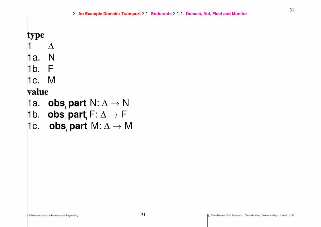
1 We analyse the composite traffic system into
a. a composite road net,
b. a composite fleet (of vehicles), and
c. an atomic monitor.
a Different Approach to Requirements Engineering 30 c© Dines Bjørner 2015, Fredsvej 11, DK–2840 Holte, Denmark – May 12, 2016: 10:32
312. An Example Domain: Transport 2.1. Endurants 2.1.1. Domain, Net, Fleet and Monitor
type
1 ∆
1a. N
1b. F
1c. M
value
1a. obs part N: ∆ → N
1b. obs part F: ∆ → F
1c. obs part M: ∆ → M
a Different Approach to Requirements Engineering 31 c© Dines Bjørner 2015, Fredsvej 11, DK–2840 Holte, Denmark – May 12, 2016: 10:32

322. An Example Domain: Transport 2.1. Endurants 2.1.1. Domain, Net, Fleet and Monitor
Applying observe part sorts [Bjø14d, Sect. 3.1.6] to a net, n:N, yields the
following.
2 The road net consists of two composite parts,
a. an aggregation of hubs and
b. an aggregation of links.
a Different Approach to Requirements Engineering 32 c© Dines Bjørner 2015, Fredsvej 11, DK–2840 Holte, Denmark – May 12, 2016: 10:32

332. An Example Domain: Transport 2.1. Endurants 2.1.1. Domain, Net, Fleet and Monitor
type
2a. HA
2b. LA
value
2a. obs part HA: N → HA
2b. obs part LA: N → LA
a Different Approach to Requirements Engineering 33 c© Dines Bjørner 2015, Fredsvej 11, DK–2840 Holte, Denmark – May 12, 2016: 10:32

342. An Example Domain: Transport 2.1. Endurants 2.1.2. Hubs and Links
2.1.2. Hubs and Links
Applying observe part types [Bjø14d, Sect. 3.1.7] to hub and
link aggregates yields the following.
3 Hub aggregates are sets of hubs.
4 Link aggregates are sets of links.
5 Fleets are set of vehicles.
a Different Approach to Requirements Engineering 34 c© Dines Bjørner 2015, Fredsvej 11, DK–2840 Holte, Denmark – May 12, 2016: 10:32

352. An Example Domain: Transport 2.1. Endurants 2.1.2. Hubs and Links
type
3 H, HS = H-set
4 L, LS = L-set
5 V, VS = V-set
value
3 obs part HS: HA → HS
4 obs part LS: LA → LS
5 obs part VS: F → VS
6 We introduce some auxiliary
functions.
a. links extracts the links of a
network.
b. hubs extracts the hubs of a
network.
value
6a. links: ∆ → L-set
6a. links(δ ) ≡ obs part LS(obs part LA(obs
6b. hubs: ∆ → H-set
6b. hubs(δ ) ≡ obs part HS(obs part HA(obs
a Different Approach to Requirements Engineering 35 c© Dines Bjørner 2015, Fredsvej 11, DK–2840 Holte, Denmark – May 12, 2016: 10:32

362. An Example Domain: Transport 2.1. Endurants 2.1.3. Unique Identifiers
2.1.3. Unique Identifiers
Applying observe unique identifier [Bjø14d, Sect. 3.2] to
the observed parts yields the following.
7 Nets, hub and link aggregates, hubs and links, fleets, vehicles and
the monitor all
a. have unique identifiers
b. such that all such are distinct, and
c. with corresponding observers.
a Different Approach to Requirements Engineering 36 c© Dines Bjørner 2015, Fredsvej 11, DK–2840 Holte, Denmark – May 12, 2016: 10:32

372. An Example Domain: Transport 2.1. Endurants 2.1.3. Unique Identifiers
type
7a. NI, HAI, LAI, HI, LI, FI, VI, MI
value
7c. uid NI: N → NI
7c. uid HAI: HA → HAI
7c. uid LAI: LA → LAI
7c. uid HI: H → HI
7c. uid LI: L → LI
7c. uid FI: F → FI
7c. uid VI: V → VI
7c. uid MI: M → MI
axiom
7b. NI⋂
HAI=Ø, NI⋂
LAI=Ø, NI⋂
HI=Ø, etc.
where axiom 7b.. is expressed semi-formally, in mathematics.
a Different Approach to Requirements Engineering 37 c© Dines Bjørner 2015, Fredsvej 11, DK–2840 Holte, Denmark – May 12, 2016: 10:32

382. An Example Domain: Transport 2.1. Endurants 2.1.3. Unique Identifiers
We introduce some auxiliary functions:
8 xtr lis extracts all link identifiers of a traffic system.
9 xtr his extracts all hub identifiers of a traffic system.
10 Given an appropriate link identifier and a net get link ‘retrieves’ the designated
link.
11 Given an appropriate hub identifier and a net get hub ‘retrieves’ the designated
hub.
a Different Approach to Requirements Engineering 38 c© Dines Bjørner 2015, Fredsvej 11, DK–2840 Holte, Denmark – May 12, 2016: 10:32

392. An Example Domain: Transport 2.1. Endurants 2.1.3. Unique Identifiers
value
8 xtr lis: ∆ → LI-set
8 xtr lis(δ ) ≡8 let ls = links(δ ) in uid LI(l)|l:L•l ∈ ls end
9 xtr his: ∆ → HI-set
9 xtr his(δ ) ≡9 let hs = hubs(δ ) in uid HI(h)|h:H•k ∈ hs end
10 get link: LI → ∆∼→ L
10 get link(li)(δ ) ≡10 let ls = links(δ ) in
10 let l:L • l ∈ ls ∧ li=uid LI(l) in l end end
10 pre: li ∈ xtr lis(δ )
11 get hub: HI → ∆∼→ H
11 get hub(hi)(δ ) ≡11 let hs = hubs(δ ) in
11 let h:H • h ∈ hs ∧ hi=uid HI(h) in h end end
11 pre: hi ∈ xtr his(δ )
a Different Approach to Requirements Engineering 39 c© Dines Bjørner 2015, Fredsvej 11, DK–2840 Holte, Denmark – May 12, 2016: 10:32

402. An Example Domain: Transport 2.1. Endurants 2.1.4. Mereology
2.1.4. MereologyApplying observe mereology [Bjø14d, Sect. 3.3.2] to hubs, links, vehicles and
the monitor yields the following.
12 Hub mereologies reflect that they are connected to zero, one or more links.
13 Link mereologies reflect that they are connected to exactly two distinct hubs.
14 Vehicle mereologies reflect that they are connected to the monitor.
15 The monitor mereology reflects that it is connected to all vehicles.
16 For all hubs of any net it must be the case that their mereology designates links
of that net.
17 For all links of any net it must be the case that their mereologies designates hubs
of that net.
18 For all transport domains it must be the case that
a. the mereology of vehicles of that system designates the monitor of that
system, and that
b. the mereology of the monitor of that system designates vehicles of that
system.
a Different Approach to Requirements Engineering 40 c© Dines Bjørner 2015, Fredsvej 11, DK–2840 Holte, Denmark – May 12, 2016: 10:32

412. An Example Domain: Transport 2.1. Endurants 2.1.4. Mereology
value
12 obs mereo H: H → LI-set
13 obs mereo L: L → HI-set
axiom
13 ∀ l:L•card obs mereo L(l)=2
value
14 obs mereo V: V → MI
15 obs mereo M: M → VI-set
axiom
16 ∀ δ :∆, hs:HS•hs=hubs(δ ), ls:LS•ls=links(δ ) •
16 ∀ h:H•h ∈ hs•obs mereo H(h)⊆xtr lis(δ ) ∧17 ∀ l:L•l ∈ ls•obs mereo L(l)⊆xtr his(δ ) ∧18a. let f:F•f=obs part F(δ ) ⇒18a. let m:M•m=obs part M(δ ),
18a. vs:VS•vs=obs part VS(f) in
18a. ∀ v:V•v ∈ vs⇒uid V(v) ∈ obs mereo M(m)
18b. ∧ obs mereo M(m) = uid V(v)|v:V•v ∈ vs18b. end end
a Different Approach to Requirements Engineering 41 c© Dines Bjørner 2015, Fredsvej 11, DK–2840 Holte, Denmark – May 12, 2016: 10:32

422. An Example Domain: Transport 2.1. Endurants 2.1.5. Attributes, I
2.1.5. Attributes, I
We may not have shown all of the attributes mentioned below — so
consider them informally introduced !
• Hubs:
⋄⋄ locations are considered static,
⋄⋄ hub states and hub state spaces are considered programmable;
a Different Approach to Requirements Engineering 42 c© Dines Bjørner 2015, Fredsvej 11, DK–2840 Holte, Denmark – May 12, 2016: 10:32
432. An Example Domain: Transport 2.1. Endurants 2.1.5. Attributes, I
• Links:
⋄⋄ lengths and locations are considered static,
⋄⋄ link states and link state spaces are considered programmable;
a Different Approach to Requirements Engineering 43 c© Dines Bjørner 2015, Fredsvej 11, DK–2840 Holte, Denmark – May 12, 2016: 10:32
442. An Example Domain: Transport 2.1. Endurants 2.1.5. Attributes, I
• Vehicles:
⋄⋄ manufacturer name, engine type (whether diesel, gasoline or
electric) and engine power (kW/horse power) are considered
static;
⋄⋄ velocity and acceleration may be considered reactive (i.e., a
function of gas pedal position, etc.),
⋄⋄ global position (informed via a GNSS: Global Navigation
Satellite System) and local position (calculated from a
global position) are considered biddable
a Different Approach to Requirements Engineering 44 c© Dines Bjørner 2015, Fredsvej 11, DK–2840 Holte, Denmark – May 12, 2016: 10:32

452. An Example Domain: Transport 2.1. Endurants 2.1.5. Attributes, I
Applying observe attributes [Bjø14d, Sect. 3.4.3] to hubs,
links, vehicles and the monitor yields the following.First hubs.
19 Hubs
a. have geodetic locations, GeoH,
b. have hub states which are sets of pairs of identifiers of links connected to the
hub3,
c. and have hub state spaces which are sets of hub states4.
20 For every net,
a. link identifiers of a hub state must designate links of that net.
b. Every hub state of a net must be in the hub state space of that hub.
21 We introduce an auxiliary function: xtr lis extracts all link identifiers of a hub
state.
3A hub state “signals” which input-to-output link connections are open for traffic.4A hub state space indicates which hub states a hub may attain over time.
a Different Approach to Requirements Engineering 45 c© Dines Bjørner 2015, Fredsvej 11, DK–2840 Holte, Denmark – May 12, 2016: 10:32
462. An Example Domain: Transport 2.1. Endurants 2.1.5. Attributes, I
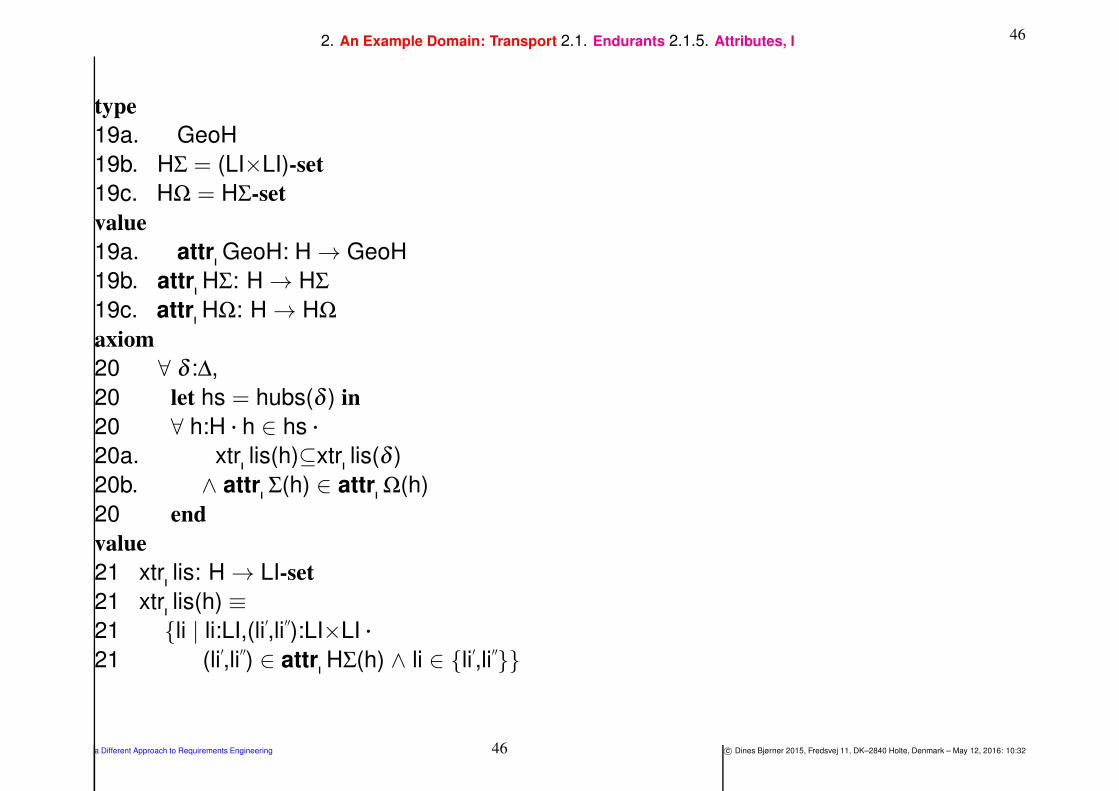
type
19a. GeoH
19b. HΣ = (LI×LI)-set
19c. HΩ = HΣ-set
value
19a. attr GeoH: H → GeoH
19b. attr HΣ: H → HΣ
19c. attr HΩ: H → HΩ
axiom
20 ∀ δ :∆,
20 let hs = hubs(δ ) in
20 ∀ h:H • h ∈ hs •
20a. xtr lis(h)⊆xtr lis(δ )
20b. ∧ attr Σ(h) ∈ attr Ω(h)
20 end
value
21 xtr lis: H → LI-set
21 xtr lis(h) ≡
21 li | li:LI,(li′,li
′′):LI×LI •
21 (li′,li
′′) ∈ attr HΣ(h) ∧ li ∈ li
′,li
′′
a Different Approach to Requirements Engineering 46 c© Dines Bjørner 2015, Fredsvej 11, DK–2840 Holte, Denmark – May 12, 2016: 10:32

472. An Example Domain: Transport 2.1. Endurants 2.1.5. Attributes, I
Then links.
22 Links have lengths.
23 Links have geodetic location.
24 Links have states and state spaces:
a. States modeled here as pairs, (hi′,hi′′), of identifiers the hubs
with which the links are connected and indicating directions
(from hub h′ to hub h′′.) A link state can thus have 0, 1, 2, 3 or 4
such pairs.
b. State spaces are the set of all the link states that a link may enjoy.
a Different Approach to Requirements Engineering 47 c© Dines Bjørner 2015, Fredsvej 11, DK–2840 Holte, Denmark – May 12, 2016: 10:32

482. An Example Domain: Transport 2.1. Endurants 2.1.5. Attributes, I
type
22 LEN
23 GeoL
24a. LΣ = (HI×HI)-set
24b. LΩ = LΣ-set
value
22 attr LEN: L → LEN
23 attr GeoL: L → GeoL
24a. attr LΣ: L → LΣ
24b. attr LΩ: L → LΩ
axiom
24 ∀ n:N •
24 let ls = xtr−links(n), hs = xtr hubs(n) in
24 ∀ l:L•l ∈ ls ⇒
24a. let lσ = attr LΣ(l) in
24a. 0≤card lσ≤4
24a. ∧ ∀ (hi′,hi
′′):(HI×HI)•(hi
′,hi
′′) ∈ lσ
24a. ⇒ hi′,hi
′′=obs mereo L(l)
24b. ∧ attr LΣ(l) ∈ attr LΩ(l)
24 end end
a Different Approach to Requirements Engineering 48 c© Dines Bjørner 2015, Fredsvej 11, DK–2840 Holte, Denmark – May 12, 2016: 10:32
492. An Example Domain: Transport 2.1. Endurants 2.1.5. Attributes, I
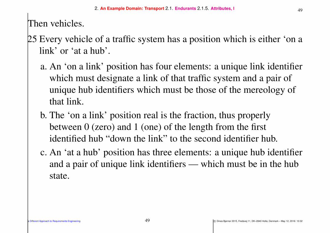
Then vehicles.
25 Every vehicle of a traffic system has a position which is either ‘on a
link’ or ‘at a hub’.
a. An ‘on a link’ position has four elements: a unique link identifier
which must designate a link of that traffic system and a pair of
unique hub identifiers which must be those of the mereology of
that link.
b. The ‘on a link’ position real is the fraction, thus properly
between 0 (zero) and 1 (one) of the length from the first
identified hub “down the link” to the second identifier hub.
c. An ‘at a hub’ position has three elements: a unique hub identifier
and a pair of unique link identifiers — which must be in the hub
state.
a Different Approach to Requirements Engineering 49 c© Dines Bjørner 2015, Fredsvej 11, DK–2840 Holte, Denmark – May 12, 2016: 10:32

502. An Example Domain: Transport 2.1. Endurants 2.1.5. Attributes, I
type
25 VPos = onL | atH
25a. onL :: LI HI HI R
25b. R = Real axiom ∀ r:R • 0≤r≤1
25c. atH :: HI LI LI
value
25 attr VPos: V → VPos
axiom
25a. ∀ n:N, onL(li,fhi,thi,r):VPos •
25a. ∃ l:L•l ∈obs part LS(obs part N(n))
25a. ⇒ li=uid L(l)∧fhi,thi=obs mereo L(l),
25c. ∀ n:N, atH(hi,fli,tli):VPos •
25c. ∃ h:H•h ∈obs part HS(obs part N(n))
25c. ⇒ hi=uid H(h)∧(fli,tli) ∈ attr LΣ(h)
a Different Approach to Requirements Engineering 50 c© Dines Bjørner 2015, Fredsvej 11, DK–2840 Holte, Denmark – May 12, 2016: 10:32
512. An Example Domain: Transport 2.1. Endurants 2.1.5. Attributes, I
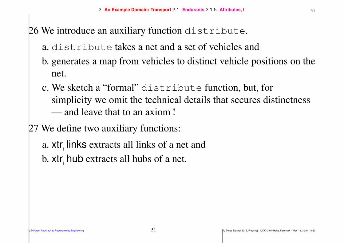
26 We introduce an auxiliary function distribute.
a. distribute takes a net and a set of vehicles and
b. generates a map from vehicles to distinct vehicle positions on the
net.
c. We sketch a “formal” distribute function, but, for
simplicity we omit the technical details that secures distinctness
— and leave that to an axiom !
27 We define two auxiliary functions:
a. xtr links extracts all links of a net and
b. xtr hub extracts all hubs of a net.
a Different Approach to Requirements Engineering 51 c© Dines Bjørner 2015, Fredsvej 11, DK–2840 Holte, Denmark – May 12, 2016: 10:32

522. An Example Domain: Transport 2.1. Endurants 2.1.5. Attributes, I
type
26b. MAP = VI →m VPos
axiom
26b. ∀ map:MAP • card dom map = card rng map
value
26 distribute: VS → N → MAP
26 distribute(vs)(n) ≡
26a. let (hs,ls) = (xtr hubs(n),xtr links(n)) in
26a. let vps = onL(uid (l),fhi,thi,r) |
26a. l:L•l ∈ls∧fhi,thi
26a. ⊆obs mereo L(l)∧0≤r≤1
26a. ∪ atH(uid H(h),fli,tli)|
26a. h:H•h ∈hs∧fli,tli
26a. ⊆obs mereo H(h) in
26b. [uid V(v) 7→vp|v:V,vp:VPos•v ∈vs∧vp∈vps ]
26 end end
a Different Approach to Requirements Engineering 52 c© Dines Bjørner 2015, Fredsvej 11, DK–2840 Holte, Denmark – May 12, 2016: 10:32
532. An Example Domain: Transport 2.1. Endurants 2.1.5. Attributes, I
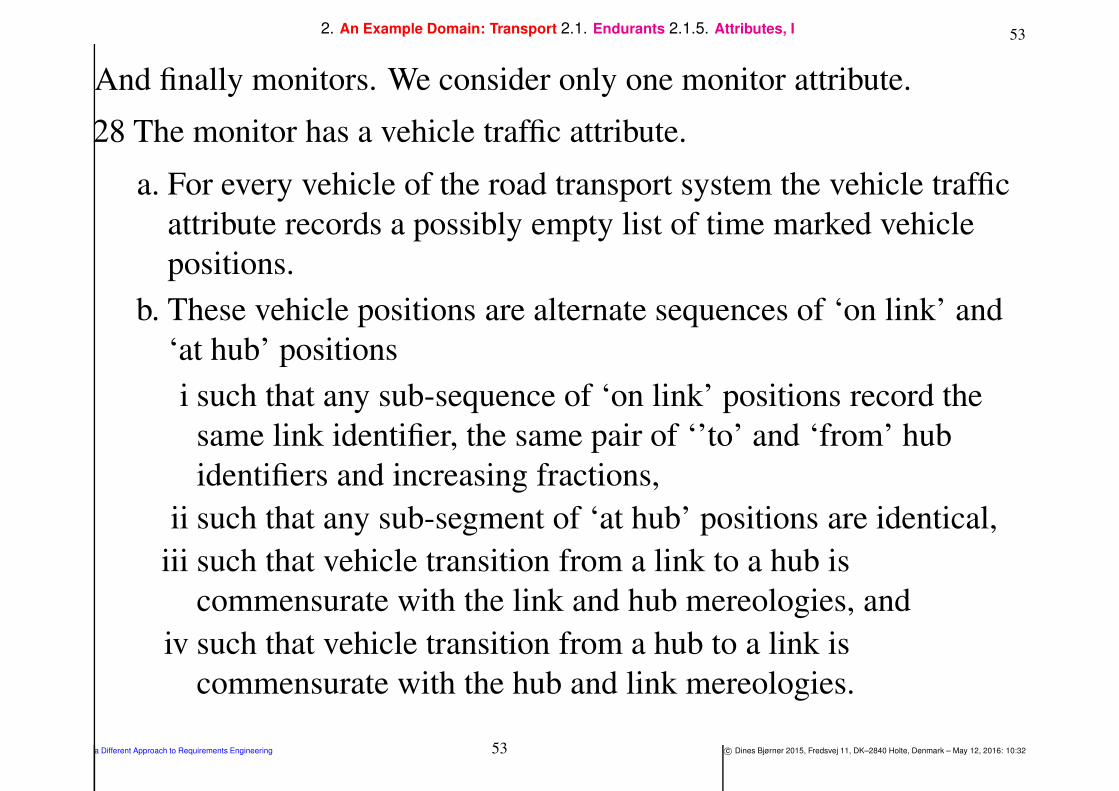
And finally monitors. We consider only one monitor attribute.
28 The monitor has a vehicle traffic attribute.
a. For every vehicle of the road transport system the vehicle traffic
attribute records a possibly empty list of time marked vehicle
positions.
b. These vehicle positions are alternate sequences of ‘on link’ and
‘at hub’ positions
i such that any sub-sequence of ‘on link’ positions record the
same link identifier, the same pair of ‘’to’ and ‘from’ hub
identifiers and increasing fractions,
ii such that any sub-segment of ‘at hub’ positions are identical,
iii such that vehicle transition from a link to a hub is
commensurate with the link and hub mereologies, and
iv such that vehicle transition from a hub to a link is
commensurate with the hub and link mereologies.
a Different Approach to Requirements Engineering 53 c© Dines Bjørner 2015, Fredsvej 11, DK–2840 Holte, Denmark – May 12, 2016: 10:32

542. An Example Domain: Transport 2.1. Endurants 2.1.5. Attributes, I
type
28 Traffic = VI →m (T × VPos)∗
value
28 attr Traffic: M → Traffic
axiom
28b. ∀ δ :∆ •
28b. let m = obs part M(δ ) in
28b. let tf = attr Traffic(m) in
28b. dom tf ⊆ xtr vis(δ ) ∧
28b. ∀ vi:VI • vi ∈ dom tf •
28b. let tr = tf(vi) in
28b. ∀ i,i+1:Nat • i,i+1⊆dom tr •
28b. let (t,vp)=tr(i),(t′,vp
′)=tr(i+1) in
28b. t<t′
28(b.)i ∧ case (vp,vp′) of
28(b.)i (onL(li,fhi,thi,r),onL(li′,fhi
′,thi
′,r
′))
28(b.)i → li=li′∧fhi=fhi
′∧thi=thi
′∧r≤r
′∧ li ∈ xtr lis(δ ) ∧ fhi,thi = obs mereo L(get link(li)(δ )),
28(b.)ii (atH(hi,fli,tli),atH(hi′,fli
′,tli
′))
28(b.)ii → hi=hi′∧fli=fli
′∧tli=tli
′∧ hi ∈ xtr his(δ ) ∧ (fli,tli) ∈ obs mereo H(get hub(hi)(δ )),
28(b.)iii (onL(li,fhi,thi,1),atH(hi,fli,tli))
28(b.)iii → li=fli∧thi=hi ∧ li,tli ⊆ xtr lis(δ ) ∧ fhi,thi=obs mereo L(get link(li)(δ ))
28(b.)iii ∧ hi ∈ xtr his(δ ) ∧ (fli,tli) ∈ obs mereo H(get hub(hi)(δ )),
28(b.)iv (atH(hi,fli,tli),onL(li′,fhi
′,thi
′,0))
28(b.)iv → etcetera,
28b. → false
28b. end end end end end
a Different Approach to Requirements Engineering 54 c© Dines Bjørner 2015, Fredsvej 11, DK–2840 Holte, Denmark – May 12, 2016: 10:32
552. An Example Domain: Transport 2.2. Perdurants
2.2. Perdurants
• Our presentation of example perdurants is not as systematic as that
of example endurants.
• Give the simple basis of endurants covered above there is now a
huge variety of perdurants, so we just select one example from each
of the three classes of perdurants (as outline in [Bjø16b]):
⋄⋄ a simple hub insertion action (Sect. ),
⋄⋄ a simple link disappearance event (Sect. ) and
⋄⋄ a not quite so simple behaviour, that of road traffic (Sect. ).
a Different Approach to Requirements Engineering 55 c© Dines Bjørner 2015, Fredsvej 11, DK–2840 Holte, Denmark – May 12, 2016: 10:32

562. An Example Domain: Transport 2.2. Perdurants 2.2.1. Hub Insertion Action
2.2.1. Hub Insertion Action
29 Initially inserted hubs, h, are characterised
a. by their unique identifier which not one of any hub in the net, n,
into which the hub is being inserted,
b. by a mereology, , of zero link identifiers, and
c. by — whatever — attributes, attrs, are needed.
30 The result of such a hub insertion is a net, n′,
a. whose links are those of n, and
b. whose hubs are those of n augmented with h.
a Different Approach to Requirements Engineering 56 c© Dines Bjørner 2015, Fredsvej 11, DK–2840 Holte, Denmark – May 12, 2016: 10:32

572. An Example Domain: Transport 2.2. Perdurants 2.2.1. Hub Insertion Action
value
29 insert hub: H → N → N
30 insert hub(h)(n) as n′
29a. pre: uid H(h) 6∈ xtr his(n)
29b. ∧ obs mereo H= 29c. ∧ ...
30a. post: obs part Ls(n) = obs part Ls(n′)
30b. ∧ obs part Hs(n) ∪ h = obs part Hs(n′)
a Different Approach to Requirements Engineering 57 c© Dines Bjørner 2015, Fredsvej 11, DK–2840 Holte, Denmark – May 12, 2016: 10:32

582. An Example Domain: Transport 2.2. Perdurants 2.2.2. Link Disappearance Event
2.2.2. Link Disappearance Event
We formalise aspects of the link disappearance event:
31 The result net, n’:N’, is not well-formed.
32 For a link to disappear there must be at least one link in the net;
33 and such a link may disappear such that
34 it together with the resulting net makes up for the “original” net.
value
31 link diss event: N × N′
× Bool
31 link diss event(n,n′
) as tf
32 pre: obs part Ls(obs part LS(n)) 6=33 post: ∃ l:L•l ∈ obs part Ls(obs part LS(n)) ⇒34 l 6∈ obs part Ls(obs part LS(n
′
))
34 ∧ n′
∪ l = obs part Ls(obs part LS(n))
a Different Approach to Requirements Engineering 58 c© Dines Bjørner 2015, Fredsvej 11, DK–2840 Holte, Denmark – May 12, 2016: 10:32

592. An Example Domain: Transport 2.2. Perdurants 2.2.3. Road Traffic
2.2.3. Road Traffic
• The analysis & description of the road traffic behaviour is
composed
⋄⋄ (i) from the description of the global values of
nets, links and hubs,
vehicles,
monitor,
a clock, and
an initial distribution, map, of vehicles, “across” the net;
⋄⋄ (ii) from the description of channels
between vehicles and
the monitor;
a Different Approach to Requirements Engineering 59 c© Dines Bjørner 2015, Fredsvej 11, DK–2840 Holte, Denmark – May 12, 2016: 10:32

602. An Example Domain: Transport 2.2. Perdurants 2.2.3. Road Traffic
⋄⋄ (iii) from the description of behaviour signatures, that is, those of
the overall road traffic system,
the vehicles, and
the monitor; and
⋄⋄ (iv) from the description of the individual behaviours, that is,
the overall road traffic system, rts,
the individual vehicles, veh, and
the monitor, mon.
a Different Approach to Requirements Engineering 60 c© Dines Bjørner 2015, Fredsvej 11, DK–2840 Holte, Denmark – May 12, 2016: 10:32

612. An Example Domain: Transport 2.2. Perdurants 2.2.3. Road Traffic 2.2.3.1. Global Values:
2.2.3.1 Global Values:
• There is given some globally observable parts.
35 besides the domain, δ :∆,
36 a net, n:N,
37 a set of vehicles, vs:V-set,
38 a monitor, m:M, and
39 a clock, clock, behaviour.
40 From the net and vehicles we generate an initial distribution of
positions of vehicles.
• The n:N, vs:V-set and m:M are observable from any road traffic
system domain δ .
a Different Approach to Requirements Engineering 61 c© Dines Bjørner 2015, Fredsvej 11, DK–2840 Holte, Denmark – May 12, 2016: 10:32

622. An Example Domain: Transport 2.2. Perdurants 2.2.3. Road Traffic 2.2.3.1. Global Values:
value
35 δ :∆
36 n:N = obs part N(δ ),
36 ls:L-set=links(δ ),hs:H-set=hubs(δ ),
36 lis:LI-set=xtr lis(δ ),his:HI-set=xtr his(δ )
37 va:VS=obs part VS(obs part F(δ )),
37 vs:Vs-set=obs part Vs(va),
37 vis:VI-set = uid VI(v)|v:V•v ∈ vs,
38 m:obs part M(δ ),
38 mi=uid MI(m),
38 ma:attributes(m)
39 clock: T → out clk ch[vi|vi:VI•vi ∈ vis ] Unit
40 vm:MAP•vpos map = distribute(vs)(n);
a Different Approach to Requirements Engineering 62 c© Dines Bjørner 2015, Fredsvej 11, DK–2840 Holte, Denmark – May 12, 2016: 10:32
632. An Example Domain: Transport 2.2. Perdurants 2.2.3. Road Traffic 2.2.3.2. Channels:
2.2.3.2 Channels:
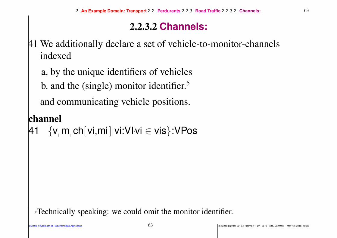
41 We additionally declare a set of vehicle-to-monitor-channels
indexed
a. by the unique identifiers of vehicles
b. and the (single) monitor identifier.5
and communicating vehicle positions.
channel
41 v m ch[vi,mi ]|vi:VI•vi ∈ vis:VPos
5Technically speaking: we could omit the monitor identifier.
a Different Approach to Requirements Engineering 63 c© Dines Bjørner 2015, Fredsvej 11, DK–2840 Holte, Denmark – May 12, 2016: 10:32

642. An Example Domain: Transport 2.2. Perdurants 2.2.3. Road Traffic 2.2.3.3. Behaviour Signatures:
2.2.3.3 Behaviour Signatures:
42 The road traffic system behaviour, rts, takes no arguments; and
“behaves”, that is, continues forever.
43 The vehicle behaviour
a. is indexed by the unique identifier, uid V(v):VI,
b. the vehicle mereology, in this case the single monitor identifier
mi:MI,
c. the vehicle attributes, obs attribs(v)
d. and — factoring out one of the vehicle attributes — the current
vehicle position.
e. The vehicle behaviour offers communication to the monitor
behaviour; and behaves “forever”.
a Different Approach to Requirements Engineering 64 c© Dines Bjørner 2015, Fredsvej 11, DK–2840 Holte, Denmark – May 12, 2016: 10:32

652. An Example Domain: Transport 2.2. Perdurants 2.2.3. Road Traffic 2.2.3.3. Behaviour Signatures:
44 The monitor behaviour takes
a. the monitor identifier,
b. the monitor mereology,
c. the monitor attributes,
d. and — factoring out one of the vehicle attributes — the discrete
road traffic, drtf:dRTF;
e. the behaviour otherwise behaves forever.
value
42 rts: Unit → Unit
43 veh: vi:VI × mi:MI → vp:VPos → out vm ch[vi,mi ] Unit
44 mon: m:M × vis:VI-set → RTF → in v m ch[vi,mi ]|vi:VI•vi ∈ vis,clk
a Different Approach to Requirements Engineering 65 c© Dines Bjørner 2015, Fredsvej 11, DK–2840 Holte, Denmark – May 12, 2016: 10:32

662. An Example Domain: Transport 2.2. Perdurants 2.2.3. Road Traffic 2.2.3.4. The Road Traffic System Behaviour:
2.2.3.4 The Road Traffic System Behaviour:
45 Thus we shall consider our road traffic system, rts, as
a. the concurrent behaviour of a number of vehicles and,
to “observe”, or, as we shall call it, to monitor their movements,
b. the monitor behaviour.
value
45 rts() =45a. ‖ veh(uid VI(v),mi)(vm(uid VI(v)))|v:V•v ∈ vs45b. ‖ mon(mi,vis)([vi 7→〈〉|vi:VI•vi ∈ vis ])
a Different Approach to Requirements Engineering 66 c© Dines Bjørner 2015, Fredsvej 11, DK–2840 Holte, Denmark – May 12, 2016: 10:32

672. An Example Domain: Transport 2.2. Perdurants 2.2.3. Road Traffic 2.2.3.4. The Road Traffic System Behaviour:
• where, wrt, the monitor, we
⋄⋄ dispense with the mereology and the attribute state arguments
⋄⋄ and instead just have a monitor traffic argument which
records the discrete road traffic, MAP,
initially set to “empty” traces (〈〉, of so far “no road traffic”!).
• In order for the monitor behaviour to assess the vehicle positions
⋄⋄ these vehicles communicate their positions
⋄⋄ to the monitor
⋄⋄ via a vehicle to monitor channel.
• In order for the monitor to time-stamp these positions
⋄⋄ it must be able to “read” a clock.
a Different Approach to Requirements Engineering 67 c© Dines Bjørner 2015, Fredsvej 11, DK–2840 Holte, Denmark – May 12, 2016: 10:32

682. An Example Domain: Transport 2.2. Perdurants 2.2.3. Road Traffic 2.2.3.4. The Road Traffic System Behaviour:
46 We describe here an abstraction of the vehicle behaviour at a Hub
(hi).
a. Either the vehicle remains at that hub informing the monitor of
its position,
b. or, internally non-deterministically,
i moves onto a link, tli, whose “next” hub, identified by thi, is
obtained from the mereology of the link identified by tli;
ii informs the monitor, on channel vm[vi,mi], that it is now at the
very beginning (0) of the link identified by tli, whereupon the
vehicle resumes the vehicle behaviour positioned at the very
beginning of that link,
c. or, again internally non-deterministically, the vehicle “disappears
— off the radar” !
a Different Approach to Requirements Engineering 68 c© Dines Bjørner 2015, Fredsvej 11, DK–2840 Holte, Denmark – May 12, 2016: 10:32
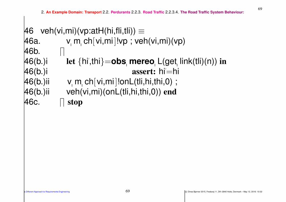
692. An Example Domain: Transport 2.2. Perdurants 2.2.3. Road Traffic 2.2.3.4. The Road Traffic System Behaviour:
46 veh(vi,mi)(vp:atH(hi,fli,tli)) ≡46a. v m ch[vi,mi ]!vp ; veh(vi,mi)(vp)
46b. ⌈⌉46(b.)i let hi
′
,thi=obs mereo L(get link(tli)(n)) in
46(b.)i assert: hi′
=hi
46(b.)ii v m ch[vi,mi ]!onL(tli,hi,thi,0) ;
46(b.)ii veh(vi,mi)(onL(tli,hi,thi,0)) end
46c. ⌈⌉ stop
a Different Approach to Requirements Engineering 69 c© Dines Bjørner 2015, Fredsvej 11, DK–2840 Holte, Denmark – May 12, 2016: 10:32

702. An Example Domain: Transport 2.2. Perdurants 2.2.3. Road Traffic 2.2.3.4. The Road Traffic System Behaviour:
47 We describe here an abstraction of the vehicle behaviour on a Link (ii).
Either
a. the vehicle remains at that link position informing the monitor of its position,
b. or, internally non-deterministically, if the vehicle’s position on the link has
not yet reached the hub,
i then the vehicle moves an arbitrary increment ℓε (less than or equal to the
distance to the hub) along the link informing the monitor of this, or
ii else,
A while obtaining a “next link” from the mereology of the hub (where that
next link could very well be the same as the link the vehicle is about to
leave),
B the vehicle informs the monitor that it is now at the hub identified by thi,
whereupon the vehicle resumes the vehicle behaviour positioned at that
hub.
c. or, internally non-deterministically, the vehicle “disappears — off the radar” !
a Different Approach to Requirements Engineering 70 c© Dines Bjørner 2015, Fredsvej 11, DK–2840 Holte, Denmark – May 12, 2016: 10:32

712. An Example Domain: Transport 2.2. Perdurants 2.2.3. Road Traffic 2.2.3.4. The Road Traffic System Behaviour:
47 veh(vi,mi)(vp:onL(li,fhi,thi,r)) ≡47a. v m ch[vi,mi ]!vp ; veh(vi,mi,va)(vp)
47b. ⌈⌉ if r + ℓε≤1
47(b.)i then
47(b.)i v m ch[vi,mi ]!onL(li,fhi,thi,r+ℓε) ;
47(b.)i veh(vi,mi)(onL(li,fhi,thi,r+ℓε))
47(b.)ii else
47(b.)iiA let li′
:LI•li′
∈ obs mereo H(get hub(thi)(n)) in
47(b.)iiB v m ch[vi,mi ]!atH(li,thi,li′
);
47(b.)iiB veh(vi,mi)(atH(li,thi,li′
)) end end
47c. ⌈⌉ stop
a Different Approach to Requirements Engineering 71 c© Dines Bjørner 2015, Fredsvej 11, DK–2840 Holte, Denmark – May 12, 2016: 10:32

722. An Example Domain: Transport 2.2. Perdurants 2.2.3. Road Traffic 2.2.3.4. The Road Traffic System Behaviour:
The Monitor Behaviour
48 The monitor behaviour evolves around
a. the monitor identifier,
b. the monitor mereology,
c. and the attributes, ma:ATTR
d. — where we have factored out as a separate arguments — a table
of traces of time-stamped vehicle positions,
e. while accepting messages
i about time
ii and about vehicle positions
f. and otherwise progressing “in[de]finitely”.
a Different Approach to Requirements Engineering 72 c© Dines Bjørner 2015, Fredsvej 11, DK–2840 Holte, Denmark – May 12, 2016: 10:32

732. An Example Domain: Transport 2.2. Perdurants 2.2.3. Road Traffic 2.2.3.4. The Road Traffic System Behaviour:
49 Either the monitor “does own work”
50 or, internally non-deterministically accepts messages from vehicles.
a. A vehicle position message, vp, may arrive from the vehicle
identified by vi.
b. That message is appended to that vehicle’s movement trace –
prefixed by time (obtained from the time channel),
c. whereupon the monitor resumes its behaviour —
d. where the communicating vehicles range over all identified
vehicles.
a Different Approach to Requirements Engineering 73 c© Dines Bjørner 2015, Fredsvej 11, DK–2840 Holte, Denmark – May 12, 2016: 10:32

742. An Example Domain: Transport 2.2. Perdurants 2.2.3. Road Traffic 2.2.3.4. The Road Traffic System Behaviour:
48 mon(mi,vis)(trf) ≡49 mon(mi,vis)(trf)
50 ⌈⌉50a. ⌈⌉⌊⌋let tvp = (clk ch?,v m ch[vi,mi ]?) in
50b. let trf′ = trf † [vi 7→ trf(vi) <tvp> ] in
50c. mon(mi,vis)(trf′)
50d. end end | vi:VI • vi ∈ vis
a Different Approach to Requirements Engineering 74 c© Dines Bjørner 2015, Fredsvej 11, DK–2840 Holte, Denmark – May 12, 2016: 10:32

752. An Example Domain: Transport 2.2. Perdurants 2.2.3. Road Traffic 2.2.3.4. The Road Traffic System Behaviour:
• We are about to complete a long, i.e., a 50 slide example (!).
• We can now comment on the full example:
⋄⋄ The domain, δ : ∆ is a manifest part.
⋄⋄ The road net, n : N is also a manifest part.
⋄⋄ The fleet, f : F , of vehicles, vs : VS, likewise, is a manifest part.
⋄⋄ But the monitor, m : M, is a concept.
a Different Approach to Requirements Engineering 75 c© Dines Bjørner 2015, Fredsvej 11, DK–2840 Holte, Denmark – May 12, 2016: 10:32

762. An Example Domain: Transport 2.2. Perdurants 2.2.3. Road Traffic 2.2.3.4. The Road Traffic System Behaviour:
One does not have to think of it as a manifest “observer”.
The vehicles are on — or off — the road (i.e., links and hubs).
We know that from a few observations and generalise to all
vehicles.
They either move or stand still. We also, similarly, know that.
Vehicles move. Yes, we know that.
Based on all these repeated observations and generalisations
we introduce the concept of vehicle traffic.
Unless positioned high above a road net — and with good
binoculars — a single person cannot really observe the traffic.
There are simply too many links, hubs, vehicles, vehicle
positions and times.
⋄⋄ Thus we conclude that, even in a richly manifest domain, we can
also “speak of”, that is, describe concepts over manifest
phenomena, including time !
a Different Approach to Requirements Engineering 76 c© Dines Bjørner 2015, Fredsvej 11, DK–2840 Holte, Denmark – May 12, 2016: 10:32

772. An Example Domain: Transport 2.3. Domain Facets
2.3. Domain Facets
• The example of this section focuses on the domain facet [Bjø10a,
2008] of instrinsics .
• It does not reflect the other domain facets:
⋄⋄ domain support technologies,
⋄⋄ domain rules, regulations & scripts,
⋄⋄ organisation & management, and
⋄⋄ human behaviour.
a Different Approach to Requirements Engineering 77 c© Dines Bjørner 2015, Fredsvej 11, DK–2840 Holte, Denmark – May 12, 2016: 10:32
782. An Example Domain: Transport 2.3. Domain Facets
• The requirements examples, i.e., the rest of this paper, thus builds
only on the domain instrinsics .
⋄⋄ This means that we shall not be able to cover
principles, technique and tools for the prescription of such
important requirements that handle failures of support
technology or humans.
⋄⋄ We shall, however point out where we think such, for example,
fault tolerance requirements prescriptions “fit in”
and refer to relevant publications for their handling.
a Different Approach to Requirements Engineering 78 c© Dines Bjørner 2015, Fredsvej 11, DK–2840 Holte, Denmark – May 12, 2016: 10:32

793. Requirements
3. Requirements
• This and the next three sections,
Sects. 3., 4. and 5., are the main sections
of these lectures’ coverage of requirements.
⋄⋄ Section 4. is the most detailed and systematic section.
⋄⋄ It covers the domain requirements operations of
projection ,
instantiation ,
determination ,
extension and, less detailed,
fitting .
a Different Approach to Requirements Engineering 79 c© Dines Bjørner 2015, Fredsvej 11, DK–2840 Holte, Denmark – May 12, 2016: 10:32

803. Requirements
⋄⋄ Section 5. surveys the interface requirements issues of shared
phenomena:
shared endurants,
shared actions,
shared events and
shared behaviour ,
and “completes” the exemplification of the detailed domain
extension of our requirements into a road pricing system.
⋄⋄ Section 5. also covers the notion of derived requirements .
• This, the initial, section captures
main concepts and principles of requirements.
a Different Approach to Requirements Engineering 80 c© Dines Bjørner 2015, Fredsvej 11, DK–2840 Holte, Denmark – May 12, 2016: 10:32

813. Requirements
• Sections 3., 4., and 5. covers initial requirements .
⋄⋄ By initial requirements we shall, “operationally” speaking,
understand the requirements
that are derived from the general principles outlined in these
sections
⋄⋄ In contrast to these are the further requirements that are typically
derived
either from the domain facet descriptions of intrinsic , the
support technology, the rules & regulations , the organisation& management , and the human behaviour facets [Bjø10a] —
not covered in this paper,
(and/)or by more conventional means
[DvLF93, Jac01, ZH04, Lau02, JHJ07, OD08, van09].
a Different Approach to Requirements Engineering 81 c© Dines Bjørner 2015, Fredsvej 11, DK–2840 Holte, Denmark – May 12, 2016: 10:32

823. Requirements
Definition 1 Requirements (I): By a requirements we understand
(cf., IEEE Standard 610.12):
• “A condition or capability needed by a user to solve a
problem or achieve an objective”
• The objective of requirements engineering is to create a
requirements prescription:
⋄⋄ A requirements prescription specifies observable properties
of endurants and perdurants of the machine such as the
requirements stake-holders wish them to be
⋄⋄ The machine is what is required: that is, the hardware and
software that is to be designed and which are to satisfy the
requirements
a Different Approach to Requirements Engineering 82 c© Dines Bjørner 2015, Fredsvej 11, DK–2840 Holte, Denmark – May 12, 2016: 10:32

833. Requirements
• A requirements prescription thus (putatively) expresses what there
should be.
• A requirements prescription expresses nothing about the design of
the possibly desired (required) software.
• But as the requirements prescription is presented in the form of a
model, one can base the design on that model.
• We shall show how a major part of a requirements prescription can
be “derived” from “its” prerequisite domain description.
a Different Approach to Requirements Engineering 83 c© Dines Bjørner 2015, Fredsvej 11, DK–2840 Holte, Denmark – May 12, 2016: 10:32
843. Requirements
Rule 1. The “Golden Rule” of Requirements Engineering:
Prescribe only those requirements that can be objectively shown to
hold for the designed software 6
• “Objectively shown” means that the designed software can
⋄⋄ either be tested,
⋄⋄ or be model checked,
⋄⋄ or be proved (verified),
to satisfy the requirements.
• Caveat7
6 marks the end of a rule.7Will not be illustrated !
a Different Approach to Requirements Engineering 84 c© Dines Bjørner 2015, Fredsvej 11, DK–2840 Holte, Denmark – May 12, 2016: 10:32

853. Requirements
Rule 2. An “Ideal Rule” of Requirements Engineering: When
prescribing (including formalising) requirements, also formulate tests
and properties for model checking and theorems whose proof should
show adherence to the requirements
• The rule is labelled “ideal” since such precautions will not be
shown in this seminar.
• The rule is clear.
• It is a question for proper management to see that it is adhered to.
• See the “Caveat” above !
a Different Approach to Requirements Engineering 85 c© Dines Bjørner 2015, Fredsvej 11, DK–2840 Holte, Denmark – May 12, 2016: 10:32
863. Requirements
Rule 3. Requirements Adequacy: Make sure that requirements
cover what users expect
• That is,
⋄⋄ do not express a requirement for which you have no users,
⋄⋄ but make sure that all users’ requirements are represented or
somehow accommodated.
• In other words:
⋄⋄ the requirements gathering process needs to be like an extremely
“fine-meshed net”:
⋄⋄ One must make sure that all possible stake-holders have been
involved in the requirements acquisition process,
⋄⋄ and that possible conflicts and other inconsistencies have been
obviated.
a Different Approach to Requirements Engineering 86 c© Dines Bjørner 2015, Fredsvej 11, DK–2840 Holte, Denmark – May 12, 2016: 10:32

873. Requirements
Rule 4. Requirements Implementability: Make sure that
requirements are implementable
• That is, do not express a requirement for which you have no
assurance that it can be implemented.
• In other words,
⋄⋄ although the requirements phase is not a design phase,
⋄⋄ one must tacitly assume, perhaps even indicate, somehow, that
an implementation is possible.
• But the requirements in and by themselves, may stay short of
expressing such designs.
• Caveat !
a Different Approach to Requirements Engineering 87 c© Dines Bjørner 2015, Fredsvej 11, DK–2840 Holte, Denmark – May 12, 2016: 10:32
883. Requirements
Definition 2: Requirements (II):
• By requirements we shall understand
⋄⋄ a document
⋄⋄ which prescribes desired properties of
⋄⋄ a machine:
what endurants the machine shall “maintain”, and
what the machine shall (must; not should) offer of
∗ functions and of
∗ behaviours
while also expressing which events the machine shall “handle”
a Different Approach to Requirements Engineering 88 c© Dines Bjørner 2015, Fredsvej 11, DK–2840 Holte, Denmark – May 12, 2016: 10:32

893. Requirements
• By a machine that “maintains” endurants we shall mean:
⋄⋄ a machine which, “between” users’ use of that machine,
⋄⋄ “keeps” the data that represents these entities.
• From earlier we repeat:
Definition 3: Machine: By machine we shall understand a, or the,
combination of hardware and software that is the target for, or result of
the required computing systems development
• So this, then, is a main objective of requirements development:
• to start towards the design of the hardware + software for the
computing system.
a Different Approach to Requirements Engineering 89 c© Dines Bjørner 2015, Fredsvej 11, DK–2840 Holte, Denmark – May 12, 2016: 10:32

903. Requirements
Definition 4: Requirements (III): To specify the machine
• When we express requirements and wish to “convert” such
requirements to a realisation, i.e., an implementation, then we find
⋄⋄ that some requirements (parts) imply certain properties to hold of
the hardware on which the software to be developed is to “run”,
⋄⋄ and, obviously, that remaining — probably the larger parts of the
— requirements imply certain properties to hold of that software.
a Different Approach to Requirements Engineering 90 c© Dines Bjørner 2015, Fredsvej 11, DK–2840 Holte, Denmark – May 12, 2016: 10:32
913. Requirements
• Whereas domain descriptions may describe phenomena that cannot
be computed,
• requirements prescriptions must describe computable phenomena.
a Different Approach to Requirements Engineering 91 c© Dines Bjørner 2015, Fredsvej 11, DK–2840 Holte, Denmark – May 12, 2016: 10:32
923. Requirements 3.1. Some Requirements Aspects
3.1. Some Requirements Aspects
• We shall unravel requirements in two stages —
⋄⋄ (i) the first stage is sketchy (and thus informal)
⋄⋄ (ii) while the last stage is systematic
and both informal and formal.
⋄⋄ The sketchy stage consists of
a narrative problem/objective sketch ,
a narrative system requirements sketch , and
a narrative user & external equipment requirements sketch .
a Different Approach to Requirements Engineering 92 c© Dines Bjørner 2015, Fredsvej 11, DK–2840 Holte, Denmark – May 12, 2016: 10:32

933. Requirements 3.1. Some Requirements Aspects
• The narrative and formal stage
⋄⋄ consists of
design assumptions and
design requirements .
⋄⋄ It is systematic, and mandates
both strict narrative
and formal
prescriptions.
⋄⋄ And it is “derivable” from the domain description.
• In a sense stage (i) is made superfluous once stage (ii) has been
completed.
• The formal, engineering design work is to based on stage (ii).
a Different Approach to Requirements Engineering 93 c© Dines Bjørner 2015, Fredsvej 11, DK–2840 Holte, Denmark – May 12, 2016: 10:32

943. Requirements 3.1. Some Requirements Aspects
• The purpose of the two stages (i–ii) is twofold:
⋄⋄ to gently lead the requirements engineer and the reader
into the requirements problems
⋄⋄ while leading the requirements engineer and reader
to focus on the very requirements essentials.
a Different Approach to Requirements Engineering 94 c© Dines Bjørner 2015, Fredsvej 11, DK–2840 Holte, Denmark – May 12, 2016: 10:32

953. Requirements 3.1. Some Requirements Aspects 3.1.1. Requirements Sketches
3.1.1. Requirements Sketches
3.1.1.1 Problem, Solution and Objective Sketch
Definition 5 Problem, Solution and Objective Sketch: By a
problem, solution and objective sketch we understand
• a narrative which emphasises
• what the problem to be solved is,
• outlines a possible solution
• and sketches an objective of the solution
a Different Approach to Requirements Engineering 95 c© Dines Bjørner 2015, Fredsvej 11, DK–2840 Holte, Denmark – May 12, 2016: 10:32

963. Requirements 3.1. Some Requirements Aspects 3.1.1. Requirements Sketches 3.1.1.1. Problem, Solution and Objective Sketch
Example 1 The Problem/Objective Requirements: A Sketch:
• The problem is that of traffic congestion.
• The chosen solution is to [build and] operate
a toll-road system integrated into a road net
and charge toll-road users a usage fee.
• The objective is therefore to create a road-pricing product.
⋄⋄ By a road-pricing product we shall understand an IT-based system
containing C&C equipment and software
that enables the recording of vehicle movements
within the toll-road and thus enables
∗ the owner of the road net to charge
∗ the owner of the vehicles
∗ fees for the usage of that toll-road
a Different Approach to Requirements Engineering 96 c© Dines Bjørner 2015, Fredsvej 11, DK–2840 Holte, Denmark – May 12, 2016: 10:32

973. Requirements 3.1. Some Requirements Aspects 3.1.1. Requirements Sketches 3.1.1.2. Systems Requirements
3.1.1.2 Systems Requirements
Definition 6 System Requirements: By a system
requirements narrative we understand
• a narrative which emphasises
• the overall assumed and/or required
• hardware and software system equipment
a Different Approach to Requirements Engineering 97 c© Dines Bjørner 2015, Fredsvej 11, DK–2840 Holte, Denmark – May 12, 2016: 10:32

983. Requirements 3.1. Some Requirements Aspects 3.1.1. Requirements Sketches 3.1.1.2. Systems Requirements
Example 2 The Road-pricing System Requirements: A Narrative:
• The requirements are based on the following
constellation of system equipment:
⋄⋄ there is assumed a GNSS:
a GLOBAL NAVIGATION SATELLITE SYSTEM;
⋄⋄ there are vehicles equipped with GNSS receivers;
⋄⋄ there is a well-delineated road net called a toll-road net
with specially equipped toll-gates with
vehicle identification sensors,
exit barriers which afford (only specially equipped)
vehicles to exit8 from the toll-road net;
and
⋄⋄ there is a road-pricing calculator.
8We omit consideration of entry barriers.
a Different Approach to Requirements Engineering 98 c© Dines Bjørner 2015, Fredsvej 11, DK–2840 Holte, Denmark – May 12, 2016: 10:32

993. Requirements 3.1. Some Requirements Aspects 3.1.1. Requirements Sketches 3.1.1.2. Systems Requirements
• The system to be designed (from the requirements) is
the road-pricing calculator.
• These four system elements are required
to behave and interact as follows:
⋄⋄ The GNSS is assumed to continuously offer vehicles
information about their global position;
⋄⋄ vehicles shall contain a GNSS receiver
which based on the global position information
shall regularly calculate their timed local position
and offer this to the calculator —
while otherwise cruising the general road net
as well as the toll-road net,
the latter while carefully moving through toll-gates;
a Different Approach to Requirements Engineering 99 c© Dines Bjørner 2015, Fredsvej 11, DK–2840 Holte, Denmark – May 12, 2016: 10:32
1003. Requirements 3.1. Some Requirements Aspects 3.1.1. Requirements Sketches 3.1.1.2. Systems Requirements
⋄⋄ toll-gates shall register the identity of vehicles passing the
toll-road and offer this information to the calculator; and
⋄⋄ the calculator shall accept all messages from vehicles and
gates and use this information to record the movements of
vehicles and bill these whenever they exit the toll-road.
a Different Approach to Requirements Engineering 100 c© Dines Bjørner 2015, Fredsvej 11, DK–2840 Holte, Denmark – May 12, 2016: 10:32

1013. Requirements 3.1. Some Requirements Aspects 3.1.1. Requirements Sketches 3.1.1.2. Systems Requirements
• The requirements are therefore to include assumptions
about
⋄⋄ the GNSS satellite and telecommunications equipment,
⋄⋄ the vehicle GNSS receiver equipment,
⋄⋄ the vehicle handling of GNSS input and forwarding, to the
road pricing system, of its interpretation of GNSS input,
⋄⋄ the toll-gate sensor equipment,
⋄⋄ the toll-gate barrier equipment,
⋄⋄ the toll-gate handling of entry, vehicle identification and exit
sensors and the forwarding of vehicle identification to the
road pricing calculator, and
⋄⋄ the communications between toll-gates and vehicles, on
“one side”, and the road pricing calculator, on the “other
side”.
a Different Approach to Requirements Engineering 101 c© Dines Bjørner 2015, Fredsvej 11, DK–2840 Holte, Denmark – May 12, 2016: 10:32

1023. Requirements 3.1. Some Requirements Aspects 3.1.1. Requirements Sketches 3.1.1.2. Systems Requirements
• It is in this sense that the requirements are for
an information technology-based system
⋄⋄ of both software and
⋄⋄ hardware —
not just hard computer and communications equipment,
but also movement sensors
and electro-mechanical “gear”
a Different Approach to Requirements Engineering 102 c© Dines Bjørner 2015, Fredsvej 11, DK–2840 Holte, Denmark – May 12, 2016: 10:32

1033. Requirements 3.1. Some Requirements Aspects 3.1.1. Requirements Sketches 3.1.1.3. User and External Equipment Requirements
3.1.1.3 User and External Equipment Requirements
Definition 7 User and External Equipment Requirements: By
a user and external equipment requirements narrative we
understand
• a narrative which emphasises assumptions about
⋄⋄ the human user and
⋄⋄ external equipment
interfaces
• to the system components
• The user and external equipment requirements
⋄⋄ detail, and thus make explicit,
⋄⋄ the assumptions listed in Example 2.
a Different Approach to Requirements Engineering 103 c© Dines Bjørner 2015, Fredsvej 11, DK–2840 Holte, Denmark – May 12, 2016: 10:32
1043. Requirements 3.1. Some Requirements Aspects 3.1.1. Requirements Sketches 3.1.1.3. User and External Equipment Requirements
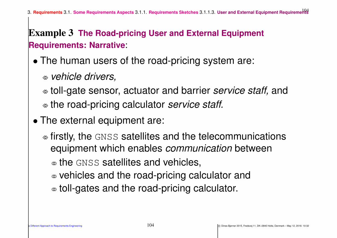
Example 3 The Road-pricing User and External Equipment
Requirements: Narrative:
• The human users of the road-pricing system are:
⋄⋄ vehicle drivers,
⋄⋄ toll-gate sensor, actuator and barrier service staff, and
⋄⋄ the road-pricing calculator service staff.
• The external equipment are:
⋄⋄ firstly, the GNSS satellites and the telecommunications
equipment which enables communication between
the GNSS satellites and vehicles,
vehicles and the road-pricing calculator and
toll-gates and the road-pricing calculator.
a Different Approach to Requirements Engineering 104 c© Dines Bjørner 2015, Fredsvej 11, DK–2840 Holte, Denmark – May 12, 2016: 10:32

1053. Requirements 3.1. Some Requirements Aspects 3.1.1. Requirements Sketches 3.1.1.3. User and External Equipment Requirements
⋄⋄ Moreover, the external equipment are
the toll-gates with their sensors:
∗ entry,
∗ vehicle identity, and
∗ exit,
and the barrier actuator.
⋄⋄ The external equipment are, finally, the vehicles !
• That is,
⋄⋄ although we do indeed exemplify
domain and requirements aspects
of users and external equipment,
⋄⋄ we do not expect to machine,
i.e., to hardware or software design these elements;
⋄⋄ they are assumed already implemented !
a Different Approach to Requirements Engineering 105 c© Dines Bjørner 2015, Fredsvej 11, DK–2840 Holte, Denmark – May 12, 2016: 10:32

1063. Requirements 3.1. Some Requirements Aspects 3.1.2. The Narrative and Formal Requirements Stage
3.1.2. The Narrative and Formal Requirements Stage
3.1.2.1 Assumption and Design Requirements
Definition 8 Assumption and Design Requirements:
• By assumption and design requirements we understand
precise prescriptions of
⋄⋄ the endurants
⋄⋄ and perdurants
of the (to be designed) system components
• and the assumptions which that design must rely upon
a Different Approach to Requirements Engineering 106 c© Dines Bjørner 2015, Fredsvej 11, DK–2840 Holte, Denmark – May 12, 2016: 10:32
1073. Requirements 3.1. Some Requirements Aspects 3.1.2. The Narrative and Formal Requirements Stage 3.1.2.1. Assumption and Design Requirements
• The specification principles, techniques and tools of expressing
• design and
• assumptions, upon which the design can be relied,
• will be covered and exemplified, extensively,
• in Sects. 4.–5.
a Different Approach to Requirements Engineering 107 c© Dines Bjørner 2015, Fredsvej 11, DK–2840 Holte, Denmark – May 12, 2016: 10:32

1083. Requirements 3.2. The Three Phases of Requirements Engineering
3.2. The Three Phases of Requirements Engineering
• There are, as we see it, three kinds of design assumptions and
requirements:
⋄⋄ domain requirements ,
⋄⋄ interface requirements and
⋄⋄ machine requirements .
a Different Approach to Requirements Engineering 108 c© Dines Bjørner 2015, Fredsvej 11, DK–2840 Holte, Denmark – May 12, 2016: 10:32

1093. Requirements 3.2. The Three Phases of Requirements Engineering
• Domain requirements are those requirements which can be
expressed solely using terms of the domain
• Interface requirements are those requirements which can be
expressed only using technical terms of both the domain and the
machine
• Machine requirements are those requirements which, in
principle, can be expressed solely using terms of the machine
a Different Approach to Requirements Engineering 109 c© Dines Bjørner 2015, Fredsvej 11, DK–2840 Holte, Denmark – May 12, 2016: 10:32

1103. Requirements 3.2. The Three Phases of Requirements Engineering
Definition 9 Verification Paradigm:
• Some preliminary designations:
⋄⋄ let D designate the the domain description;
⋄⋄ let R designate the requirements prescription, and
⋄⋄ let S designate the system design.
• Now D ,S |= R shall be read:
⋄⋄ it must be verified that the S ystem design
⋄⋄ satisfies the Requirements prescription
⋄⋄ in the context of the Domain description
a Different Approach to Requirements Engineering 110 c© Dines Bjørner 2015, Fredsvej 11, DK–2840 Holte, Denmark – May 12, 2016: 10:32

1113. Requirements 3.2. The Three Phases of Requirements Engineering
• The “in the context of D ...” term means that
⋄⋄ proofs of S oftware design correctness
⋄⋄ with respect to Requirements
⋄⋄ will often have to refer to Domain requirements assumptions.
• We refer to [GGJZ00, Gunter, Jackson and Zave, 2000] for an
analysis of a varieties of forms in which |= relate to variants of D ,
R and S .
a Different Approach to Requirements Engineering 111 c© Dines Bjørner 2015, Fredsvej 11, DK–2840 Holte, Denmark – May 12, 2016: 10:32
1123. Requirements 3.3. Order of Presentation of Requirements Prescriptions
3.3. Order of Presentation of Requirements Prescriptions
• The domain requirements development stage — as we shall see —
can be sub-staged into:
⋄⋄ projection ,
⋄⋄ instantiation ,
⋄⋄ determination ,
⋄⋄ extension and
⋄⋄ fitting .
• The interface requirements development stage — can be
sub-staged into shared:
⋄⋄ endurant,
⋄⋄ action,
⋄⋄ event and
⋄⋄ behaviour
developments, where “sharedness” pertains to phenomena shared
between, i.e., “present” in, both the domain (concretely, manifestly)
and the machine (abstractly, conceptually).
a Different Approach to Requirements Engineering 112 c© Dines Bjørner 2015, Fredsvej 11, DK–2840 Holte, Denmark – May 12, 2016: 10:32
1133. Requirements 3.3. Order of Presentation of Requirements Prescriptions
• These development stages need not be pursued in the order of the
three stages and their sub-stages.
• We emphasize that
⋄⋄ one thing is the stages and steps of development, as for example
these:
projection, instantiation, determination, extension, fitting,
shared endurants, shared actions, shared events, shared
behaviours,
etcetera,
⋄⋄ another thing is the requirements prescription that results from
these development stages and steps.
The further software development,
after and on the basis of the requirements prescription
starts only when all stages and steps of the requirements
prescription have been fully developed.
a Different Approach to Requirements Engineering 113 c© Dines Bjørner 2015, Fredsvej 11, DK–2840 Holte, Denmark – May 12, 2016: 10:32
1143. Requirements 3.3. Order of Presentation of Requirements Prescriptions
• The domain engineer is now free to rearrange the final prescription,
⋄⋄ irrespective of the order in which the various sections were
developed,
⋄⋄ in such a way as to give a most
pleasing,
pedagogic and
cohesive
reading (i.e., presentation).
• From such a requirements prescription one can therefore not
necessarily see in which order the various sections of the
prescription were developed.
a Different Approach to Requirements Engineering 114 c© Dines Bjørner 2015, Fredsvej 11, DK–2840 Holte, Denmark – May 12, 2016: 10:32
1153. Requirements 3.4. Design Requirements and Design Assumptions
3.4. Design Requirements and Design Assumptions
• A crucial distinction is between design requirements and designassumptions .
⋄⋄ The design requirements
are those requirements for which
the system designer has to implement
hardware or software
in order satisfy system user expectations
a Different Approach to Requirements Engineering 115 c© Dines Bjørner 2015, Fredsvej 11, DK–2840 Holte, Denmark – May 12, 2016: 10:32
1163. Requirements 3.4. Design Requirements and Design Assumptions
⋄⋄ The design assumptions
are those requirements for which
the system designer
does not have to implement hardware or software,
but whose properties
the designed hardware, respectively software relies on
for proper functioning
a Different Approach to Requirements Engineering 116 c© Dines Bjørner 2015, Fredsvej 11, DK–2840 Holte, Denmark – May 12, 2016: 10:32

1173. Requirements 3.4. Design Requirements and Design Assumptions
Example 4 Road Pricing System — Design Requirements:
• The design requirements for the road pricing calculator of these
lectures are for the design
⋄⋄ of that part of the vehicle software which interfaces the GNSS
receiver and the road pricing calculator
(cf. Items 129–132),
⋄⋄ of that part of the toll-gate software which interfaces the toll-gate
and the road pricing calculator
(cf. Items 137–139) and
⋄⋄ of the road pricing calculator
(cf. Items 168–181)
a Different Approach to Requirements Engineering 117 c© Dines Bjørner 2015, Fredsvej 11, DK–2840 Holte, Denmark – May 12, 2016: 10:32

1183. Requirements 3.4. Design Requirements and Design Assumptions
Example 5 Road Pricing System — Design Assumptions:
• The design assumptions for the road pricing calculator include:
⋄⋄ that vehicles behave as prescribed
in Items 128–132,
⋄⋄ that the GNSS regularly offers vehicles correct information as to
their global position
(cf. Item 129),
⋄⋄ that toll-gates behave as prescribed
in Items 134–139, and
⋄⋄ that the road net is formed and well-formed as defined in
Examples 10–12
a Different Approach to Requirements Engineering 118 c© Dines Bjørner 2015, Fredsvej 11, DK–2840 Holte, Denmark – May 12, 2016: 10:32

1193. Requirements 3.4. Design Requirements and Design Assumptions
Example 6 Toll-Gate System — Design Requirements:
• The design requirements for the toll-gate system of these lectures
are for the design of
⋄⋄ software for the toll-gate
⋄⋄ and its interfaces to the road pricing system,
⋄⋄ i.e., Items 133–134
a Different Approach to Requirements Engineering 119 c© Dines Bjørner 2015, Fredsvej 11, DK–2840 Holte, Denmark – May 12, 2016: 10:32

1203. Requirements 3.4. Design Requirements and Design Assumptions
Example 7 Toll-Gate System — Design Assumptions:
• The design assumptions for the toll-gate system include
⋄⋄ that the vehicles behave as per Items 128–132, and
⋄⋄ that the road pricing calculator behave as per Items 168–181
a Different Approach to Requirements Engineering 120 c© Dines Bjørner 2015, Fredsvej 11, DK–2840 Holte, Denmark – May 12, 2016: 10:32

1213. Requirements 3.5. Derived Requirements
3.5. Derived Requirements
• In building up the domain, interface and machine requirements
a number of machine concepts are introduced.
⋄⋄ These machine concepts enable the expression of additional
requirements.
⋄⋄ It is these we refer to as derived requirements.
⋄⋄ Techniques and tools espoused in such classical publications as
[DvLF93, Jac01, ZH04, Lau02, van09] can in those cases be
used to advantage.
a Different Approach to Requirements Engineering 121 c© Dines Bjørner 2015, Fredsvej 11, DK–2840 Holte, Denmark – May 12, 2016: 10:32

1224. Domain Requirements
4. Domain Requirements
• Domain requirements primarily express the assumptions
⋄⋄ that a design must rely upon
⋄⋄ in order that that design can be verified.
• Although domain requirements firstly express assumptions
⋄⋄ it appears that the software designer is well-advised
⋄⋄ in also implementing, as data structures and procedures,
⋄⋄ the endurants, respectively perdurants
⋄⋄ expressed in the domain requirements prescriptions.
• Whereas
⋄⋄ domain endurants are “real-life” phenomena
⋄⋄ they are now, in domain requirements prescriptions,
⋄⋄ abstract concepts (to be represented by a machine).
a Different Approach to Requirements Engineering 122 c© Dines Bjørner 2015, Fredsvej 11, DK–2840 Holte, Denmark – May 12, 2016: 10:32

1234. Domain Requirements
Definition 10 Domain Requirements Prescription: A domain
requirements prescription
• is that subset of the requirements prescription
• whose technical terms are defined in a domain description
a Different Approach to Requirements Engineering 123 c© Dines Bjørner 2015, Fredsvej 11, DK–2840 Holte, Denmark – May 12, 2016: 10:32

1244. Domain Requirements
• To determine a relevant subset all we need is collaboration with
requirements, cum domain stake-holders.
• Experimental evidence,
⋄⋄ in the form of example developments
of requirements prescriptions
from domain descriptions,
appears to show
⋄⋄ that one can formulate techniques for such developments
⋄⋄ around a few domain-description-to-requirements-prescription
operations.
⋄⋄ We suggest these:
projection ,
instantiation ,
determination ,
extension and
fitting .
a Different Approach to Requirements Engineering 124 c© Dines Bjørner 2015, Fredsvej 11, DK–2840 Holte, Denmark – May 12, 2016: 10:32
1254. Domain Requirements
• In Sect. 3.3
⋄⋄ we mentioned that the order in which one performs
⋄⋄ these description-to-prescription operations
⋄⋄ is not necessarily the order in which we have listed them here,
⋄⋄ but, with notable exceptions, one is well-served in starting out
requirements development
⋄⋄ by following this order.
a Different Approach to Requirements Engineering 125 c© Dines Bjørner 2015, Fredsvej 11, DK–2840 Holte, Denmark – May 12, 2016: 10:32

1264. Domain Requirements 4.1. Domain Projection
4.1. Domain Projection
Definition 11 Domain Projection: By a domain projection we
mean
• a subset of the domain description,
• one which projects out all those
⋄⋄ endurants:
parts,
materials and
components,
as well as
⋄⋄ perdurants:
actions,
events and
behaviours
that the stake-holders do not wish represented or relied upon by the
machine
a Different Approach to Requirements Engineering 126 c© Dines Bjørner 2015, Fredsvej 11, DK–2840 Holte, Denmark – May 12, 2016: 10:32

1274. Domain Requirements 4.1. Domain Projection
• The resulting document is a partial domain requirements prescription.
• In determining an appropriate subset
⋄⋄ the requirements engineer must secure
⋄⋄ that the final “projection prescription”
⋄⋄ is complete and consistent — that is,
that there are no “dangling references”,
i.e., that all entities
and their internal properties
that are referred to
are all properly defined.
a Different Approach to Requirements Engineering 127 c© Dines Bjørner 2015, Fredsvej 11, DK–2840 Holte, Denmark – May 12, 2016: 10:32

1284. Domain Requirements 4.1. Domain Projection 4.1.1. Domain Projection — Narrative
4.1.1. Domain Projection — Narrative
• We now start on a series of examples
• that illustrate domain requirements development.
Example 8 Domain Requirements. Projection: A Narrative Sketch:
• We require that the road pricing system shall [at most] relate to the
following domain entities – and only to these9:
⋄⋄ the net,
its links and hubs,
and their properties
(unique identifiers, mereologies and some attributes),
⋄⋄ the vehicles, as endurants, and
⋄⋄ the general vehicle behaviours, as perdurants.
9By ‘relate to . . . these’ we mean that the required system does not rely on domain phenomena that have been “projected away”.
a Different Approach to Requirements Engineering 128 c© Dines Bjørner 2015, Fredsvej 11, DK–2840 Holte, Denmark – May 12, 2016: 10:32

1294. Domain Requirements 4.1. Domain Projection 4.1.1. Domain Projection — Narrative
• We treat projection together with a concept of simplification .
• The example simplifications are
⋄⋄ vehicle positions and,
⋄⋄ related to the simpler vehicle position,
⋄⋄ vehicle behaviours.
a Different Approach to Requirements Engineering 129 c© Dines Bjørner 2015, Fredsvej 11, DK–2840 Holte, Denmark – May 12, 2016: 10:32

1304. Domain Requirements 4.1. Domain Projection 4.1.1. Domain Projection — Narrative
• To prescribe and formalise this we copy the domain description.
• From that domain description we remove all mention of
⋄⋄ the hub insertion action,
⋄⋄ the link disappearance event, and
⋄⋄ the monitor
• As a result we obtain ∆P , the projected version of the domain
requirements prescription10.
10Restrictions of the net to the toll road nets, hinted at earlier, will follow in the next
domain requirements steps.
a Different Approach to Requirements Engineering 130 c© Dines Bjørner 2015, Fredsvej 11, DK–2840 Holte, Denmark – May 12, 2016: 10:32
1314. Domain Requirements 4.1. Domain Projection 4.1.2. Domain Projection — Formalisation
4.1.2. Domain Projection — Formalisation
• The requirements prescription hinges, crucially,
⋄⋄ not only on a systematic narrative of all the
projected,
instantiated,
determinated,
extended and
fitted
specifications,
⋄⋄ but also on their formalisation.
• In the formal domain projection example
we, regretfully, omit the narrative texts.
⋄⋄ In bringing the formal texts
we keep the item numbering from Sect. 2.,
⋄⋄ where you can find the associated narrative texts.
a Different Approach to Requirements Engineering 131 c© Dines Bjørner 2015, Fredsvej 11, DK–2840 Holte, Denmark – May 12, 2016: 10:32

1324. Domain Requirements 4.1. Domain Projection 4.1.2. Domain Projection — Formalisation
Example 9 Domain Requirements — Projection:
Main Sorts
type
1 ∆P
1a. NP
1b. FP
value
1a. obs part NP: ∆P→NP
1b. obs part FP: ∆P→FP
type
2a. HAP
2b. LAP
value
2a. obs part HA: NP → HA
2b. obs part LA: NP → LA
a Different Approach to Requirements Engineering 132 c© Dines Bjørner 2015, Fredsvej 11, DK–2840 Holte, Denmark – May 12, 2016: 10:32

1334. Domain Requirements 4.1. Domain Projection 4.1.2. Domain Projection — Formalisation
Concrete Types
type
3 HP, HSP = HP-set
4 LP, LSP = LP-set
5 VP, VSP = VP-set
value
3 obs part HSP: HAP → HSP
4 obs part LSP: LAP → LSP
5 obs part VSP: FP → VSP
6a. links: ∆P → L-set
6a. links(δ P) ≡ obs part LSR(obs part LAR(δ R))
6b. hubs: ∆P → H-set
6b. hubs(δ P) ≡ obs part HSP(obs part HAP(δ P))
a Different Approach to Requirements Engineering 133 c© Dines Bjørner 2015, Fredsvej 11, DK–2840 Holte, Denmark – May 12, 2016: 10:32

1344. Domain Requirements 4.1. Domain Projection 4.1.2. Domain Projection — Formalisation
Unique Identifiers
type
7a. HI, LI, VI, MI
value
7c. uid HI: HP → HI
7c. uid LI: LP → LI
7c. uid VI: VP → VI
7c. uid MI: MP → MI
axiom
7b. HI⋂
LI=Ø, HI⋂
VI=Ø, HI⋂
MI=Ø,
7b. LI⋂
VI=Ø, LI⋂
MI=Ø, VI⋂
MI=Ø
a Different Approach to Requirements Engineering 134 c© Dines Bjørner 2015, Fredsvej 11, DK–2840 Holte, Denmark – May 12, 2016: 10:32

1354. Domain Requirements 4.1. Domain Projection 4.1.2. Domain Projection — Formalisation
Mereology
value
12 obs mereo HP: HP → LI-set
13 obs mereo LP: LP → HI-set
13 axiom ∀ l:LP• card obs mereo LP(l)=2
14 obs mereo VP: VP → MI
15 obs mereo MP: MP → VI-set
axiom
16 ∀ δ P :∆P, hs:HS•hs=hubs(δ ), ls:LS•ls=links(δ P) ⇒
16 ∀ h:HP•h ∈ hs ⇒
16 obs mereo HP(h)⊆xtr his(δ P) ∧
17 ∀ l:LP•l ∈ ls •
16 obs mereo LP(l)⊆xtr lis(δ P) ∧
18a. let f:FP•f=obs part FP(δ P) ⇒
18a. vs:VSP•vs=obs part VSP(f) in
18a. ∀ v:VP•v ∈ vs ⇒
18a. uid VP(v) ∈ obs mereo MP(m) ∧
18b. obs mereo MP(m)
18b. = uid VP(v)|v:V•v ∈ vs
18b. end
a Different Approach to Requirements Engineering 135 c© Dines Bjørner 2015, Fredsvej 11, DK–2840 Holte, Denmark – May 12, 2016: 10:32

1364. Domain Requirements 4.1. Domain Projection 4.1.2. Domain Projection — Formalisation
Attributes: We project attributes of hubs, links and vehicles.First hubs:
type
19a. GeoH
19b. HΣP = (LI×LI)-sett
19c. HΩP = HΣP-set
value
19b. attr HΣP: HP → HΣP
19c. attr HΩP: HP → HΩP
axiom
20 ∀ δ P:∆P,
20 let hs = hubs(δ P) in
20 ∀ h:HP• h ∈ hs •
20a. xtr lis(h)⊆xtr lis(δ P)
20b. ∧ attr ΣP(h) ∈ attr ΩP(h)
20 end
a Different Approach to Requirements Engineering 136 c© Dines Bjørner 2015, Fredsvej 11, DK–2840 Holte, Denmark – May 12, 2016: 10:32

1374. Domain Requirements 4.1. Domain Projection 4.1.2. Domain Projection — Formalisation
Then links:
type
23 GeoL
24a. LΣP = (HI×HI)-set
24b. LΩP = LΣP-set
value
23 attr GeoL: L → GeoL
24a. attr LΣP: LP → LΣP
24b. attr LΩP: LP → LΩP
axiom
24a.− 24b. on Slide 47.
a Different Approach to Requirements Engineering 137 c© Dines Bjørner 2015, Fredsvej 11, DK–2840 Holte, Denmark – May 12, 2016: 10:32

1384. Domain Requirements 4.1. Domain Projection 4.1.2. Domain Projection — Formalisation
Finally vehicles:
• For ‘road pricing’ we need vehicle positions.
⋄⋄ But, for “technical reasons”,
⋄⋄ we must abstain from the detailed description
⋄⋄ given in Items 25–25c.11
• We therefore simplify vehicle positions.
11The ‘technical reasons’ are that we assume that the GNSScannot provide us with direction of vehicle movement and therefore we cannot, using only the GNSSprovide the details of ‘offset’ along a link (onL )
nor the “from/to link” at a hub (atH ).
a Different Approach to Requirements Engineering 138 c© Dines Bjørner 2015, Fredsvej 11, DK–2840 Holte, Denmark – May 12, 2016: 10:32

1394. Domain Requirements 4.1. Domain Projection 4.1.2. Domain Projection — Formalisation
51 A simplified vehicle position designates
a. either a link
b. or a hub,
type
51 SVPos = SonL | SatH
51a. SonL :: LI
51b. SatH :: HI
axiom
25a.’ ∀ n:N, SonL(li):SVPos •
25a.’ ∃ l:L•l ∈obs part LS(obs part N(n)) ⇒ li=uid L(l)
25c.’ ∀ n:N, SatH(hi):SVPos •
25c.’ ∃ h:H•h ∈obs part HS(obs part N(n)) ⇒ hi=uid H(h)
a Different Approach to Requirements Engineering 139 c© Dines Bjørner 2015, Fredsvej 11, DK–2840 Holte, Denmark – May 12, 2016: 10:32

1404. Domain Requirements 4.1. Domain Projection 4.1.2. Domain Projection — Formalisation
Global Values
value
35 δ P:∆P,
36 n:NP = obs part NP(δ P),
36 ls:LP-set = links(δ P),
36 hs:HP-set = hubs(δ P),
36 lis:LI-set = xtr lis(δ P),
36 his:HI-set = xtr his(δ P)
a Different Approach to Requirements Engineering 140 c© Dines Bjørner 2015, Fredsvej 11, DK–2840 Holte, Denmark – May 12, 2016: 10:32

1414. Domain Requirements 4.1. Domain Projection 4.1.2. Domain Projection — Formalisation
Behaviour Signatures: We omit the monitor behaviour.
52 We leave the vehicle behaviours’ attribute argument undefined.
type
52 ATTR
value
42 trsP: Unit → Unit
43 vehP: VI×MI×ATTR → ... Unit
The System Behaviour: We omit the monitor behaviour.
value
45a. trsP()=‖vehP(uid VI(v),obs mereo V(v), ) | v:VP•v ∈ vs
a Different Approach to Requirements Engineering 141 c© Dines Bjørner 2015, Fredsvej 11, DK–2840 Holte, Denmark – May 12, 2016: 10:32

1424. Domain Requirements 4.1. Domain Projection 4.1.2. Domain Projection — Formalisation
The Vehicle Behaviour:
• Given the simplification of vehicle positions
• we simplify the vehicle behaviour given in Items 46–47
46′ veh(vi,mi)(vp:SatH(hi)) ≡46a.′ v m ch[vi,mi ]!SatH(hi) ; veh(vi,mi)(SatH(hi))
46(b.)i’ ⌈⌉ let li:LI•li ∈ obs mereo H(get hub(hi)(n)) in
46(b.)ii′ v m ch[vi,mi ]!SonL(li) ; veh(vi,mi)(SonL(li)) end
46c.′ ⌈⌉ stop
47′ veh(vi,mi)(vp:SonL(li)) ≡47a.′ v m ch[vi,mi ]!SonL(li) ; veh(vi,mi,va)(SonL(li))
47(b.)iiA′ ⌈⌉ let hi:HI•hi ∈ obs mereo L(get link(li)(n)) in
47(b.)iiB′ v m ch[vi,mi ]!SatH(hi) ; veh(vi,mi)(atH(hi)) end
47c.′ ⌈⌉ stop
a Different Approach to Requirements Engineering 142 c© Dines Bjørner 2015, Fredsvej 11, DK–2840 Holte, Denmark – May 12, 2016: 10:32

1434. Domain Requirements 4.1. Domain Projection 4.1.2. Domain Projection — Formalisation
• We can simplify Items 46′–47c.′ further.
53 veh(vi,mi)(vp) ≡54 v m ch[vi,mi ]!vp ; veh(vi,mi,va)(vp)
55 ⌈⌉ case vp of
55 SatH(hi) →56 let li:LI•li ∈ obs mereo H(get hub(hi)(n)) in
57 v m ch[vi,mi ]!SonL(li) ; veh(vi,mi)(SonL(li)) end,
55 SonL(li) →58 let hi:HI•hi ∈ obs mereo L(get link(li)(n)) in
59 v m ch[vi,mi ]!SatH(hi) ; veh(vi,mi)(atH(hi)) end end
60 ⌈⌉ stop
a Different Approach to Requirements Engineering 143 c© Dines Bjørner 2015, Fredsvej 11, DK–2840 Holte, Denmark – May 12, 2016: 10:32

1444. Domain Requirements 4.1. Domain Projection 4.1.2. Domain Projection — Formalisation
53 This line coalesces Items 46′ and 47′.
54 Coalescing Items 46a.′ and 47′.
55 Captures the distinct parameters of Items 46′ and 47′.
56 Item 46(b.)i′.
57 Item 46(b.)ii′.
58 Item 47(b.)iiA′.
59 Item 47(b.)iiB′.
60 Coalescing Items 46c.′ and 47c.′.
a Different Approach to Requirements Engineering 144 c© Dines Bjørner 2015, Fredsvej 11, DK–2840 Holte, Denmark – May 12, 2016: 10:32
1454. Domain Requirements 4.1. Domain Projection 4.1.2. Domain Projection — Formalisation
• The above vehicle behaviour definition
⋄⋄ will be transformed (i.e., further “refined”)
⋄⋄ in Sect. 5.4’s Example 18;
⋄⋄ cf. Items 128– 132 on Slide 208
a Different Approach to Requirements Engineering 145 c© Dines Bjørner 2015, Fredsvej 11, DK–2840 Holte, Denmark – May 12, 2016: 10:32

1464. Domain Requirements 4.1. Domain Projection 4.1.3. Discussion
4.1.3. Discussion
• Domain projection can also be achieved by
⋄⋄ developing a “completely new” domain description —
⋄⋄ typically on the basis of one or more existing domain
description(s) —
⋄⋄ where that “new” description now takes the role
⋄⋄ of being the project domain requirements.
a Different Approach to Requirements Engineering 146 c© Dines Bjørner 2015, Fredsvej 11, DK–2840 Holte, Denmark – May 12, 2016: 10:32

1474. Domain Requirements 4.2. Domain Instantiation
4.2. Domain Instantiation
Definition 12 Instantiation: By domain instantiation we mean
• a refinement of the partial domain requirements prescription
• (resulting from the projection step)
• in which the refinements aim at rendering the
⋄⋄ endurants:
parts,
materials and
components,
as well as the
⋄⋄ perdurants:
actions,
events and
behaviours
of the domain requirements prescription
• more concrete, more specific
a Different Approach to Requirements Engineering 147 c© Dines Bjørner 2015, Fredsvej 11, DK–2840 Holte, Denmark – May 12, 2016: 10:32

1484. Domain Requirements 4.2. Domain Instantiation
• Properties that hold of the projected domain shall also hold of the
(therefrom) instantiated domain.
• Refinement of endurants can be expressed
⋄⋄ either in the form of concrete types,
⋄⋄ or of further “delineating” axioms over sorts,
⋄⋄ or of a combination of concretisation and axioms.
• We shall exemplify the third possibility.
• Example 10 express requirements that the road net
⋄⋄ (on which the road-pricing system is to be based)
must satisfy.
• Refinement of perdurants will not be illustrated
(other than the simplification of the vehicle projected behaviour).
a Different Approach to Requirements Engineering 148 c© Dines Bjørner 2015, Fredsvej 11, DK–2840 Holte, Denmark – May 12, 2016: 10:32

1494. Domain Requirements 4.2. Domain Instantiation 4.2.1. Domain Instantiation
4.2.1. Domain Instantiation
Example 10 Domain Requirements. Instantiation Road Net:
• We now require that there is, as before, a road net, nI :NI ,
which can be understood as consisting of two, “connected
sub-nets”.
⋄⋄ A toll-road net, trnI :TRNI , cf. Fig. 1 on the following slide,
⋄⋄ and an ordinary road net, nP ′.
⋄⋄ The two are connected as follows:
The toll-road net, trnI , borders some toll-road plazas,
in Fig. 1 on the next slide shown by white filled circles.
These toll-road plaza hubs are proper hubs of the
‘ordinary’ road net, n′P
.
a Different Approach to Requirements Engineering 149 c© Dines Bjørner 2015, Fredsvej 11, DK–2840 Holte, Denmark – May 12, 2016: 10:32

150
tij
trn
tpj
... ... ...... ......
exitentry
toll−road intersection hubordinary net hub link
no
tpa tpb
tia tib tic
tpc tpm
tim
tp
ti
l
l
Figure 1: A simple, linear toll-road net
a Different Approach to Requirements Engineering 150 c© Dines Bjørner 2015, Fredsvej 11, DK–2840 Holte, Denmark – May 12, 2016: 10:32

1514. Domain Requirements 4.2. Domain Instantiation 4.2.1. Domain Instantiation
61 The instantiated domain, δI :∆I has just the net, nI :NI
being instantiated.
62 The road net consists of two “sub-nets”
a. an “ordinary” road net, no:NP ′ and
b. a toll-road net proper, trn:TRNI —
a Different Approach to Requirements Engineering 151 c© Dines Bjørner 2015, Fredsvej 11, DK–2840 Holte, Denmark – May 12, 2016: 10:32

1524. Domain Requirements 4.2. Domain Instantiation 4.2.1. Domain Instantiation
c. “connected” by an interface hil:HIL:
i That interface consists of a number of toll-road plazas
(i.e., hubs), modeled as a list of hub identifiers, hil:HI∗.
ii The toll-road plaza interface to the toll-road net,
trn:TRNI12, has each plaza, hil[i], connected to a pair of
toll-road links: an entry and an exit link: (le:L, lx:L).
iii The toll-road plaza interface to the ‘ordinary’ net, no:NP ′,
has each plaza, i.e., the hub designated by the hub
identifier hil[i], connected to one or more ordinary net
links, li1, li2, · · · , lik.
12We (sometimes) omit the subscript I when it should be clear from the context what we mean.
a Different Approach to Requirements Engineering 152 c© Dines Bjørner 2015, Fredsvej 11, DK–2840 Holte, Denmark – May 12, 2016: 10:32

1534. Domain Requirements 4.2. Domain Instantiation 4.2.1. Domain Instantiation
62b. The toll-road net, trn:TRNI , consists of three collections
(modeled as lists) of links and hubs:
i a list of pairs of toll-road entry/exit links:
〈(le1, lx1
), · · · ,(leℓ, lxℓ)〉,
ii a list of toll-road intersection hubs: 〈hi1,hi2, · · · ,hiℓ〉, and
iii a list of pairs of main toll-road (“up” and “down”) links:
〈(mli1u,mli1d
),(mi2u,mi2d
), · · · ,(miℓu,miℓd
)〉.
d. The three lists have commensurate lengths (ℓ).
a Different Approach to Requirements Engineering 153 c© Dines Bjørner 2015, Fredsvej 11, DK–2840 Holte, Denmark – May 12, 2016: 10:32

1544. Domain Requirements 4.2. Domain Instantiation 4.2.1. Domain Instantiation
type
61 ∆I
62 NI = NP ′ × HIL × TRN
62a. NP ′
62b. TRNI = (L×L)∗×H∗×(L×L)∗
62c. HIL = HI∗
axiom
62d. ∀ nI :NI•
62d. let (n∆,hil,(exll,hl,lll)) = nI in
62d. len hil = len exll = len hl = len lll + 1
62d. end
[Lecturer explains NP ′]
• The partial concretisation of the net sorts, NP, into NI requires some
additional well-formedness conditions to be satisfied.
63 The toll-road intersection hubs all13 have distinct identifiers.
63 wf dist toll road isect hub ids: H∗→Bool
63 wf dist toll road isect hub ids(hl) ≡63 len hl = card xtr his(hl)
13A ‘must’ can be inserted in front of all ‘all’s,
a Different Approach to Requirements Engineering 154 c© Dines Bjørner 2015, Fredsvej 11, DK–2840 Holte, Denmark – May 12, 2016: 10:32

1554. Domain Requirements 4.2. Domain Instantiation 4.2.1. Domain Instantiation
64 The toll-road links all have distinct identifiers.
64 wf dist toll road u d link ids: (L×L)∗→Bool
64 wf dist toll road u d link ids(lll) ≡64 2 × len lll = card xtr lis(lll)
65 The toll-road entry/exit links all have distinct identifiers.
65 wf dist e x link ids: (L×L)∗→Bool
65 wf dist e x link ids(exll) ≡65 2 × len exll = card xtr lis(exll)
66 Proper net links must not designate toll-road intersection hubs.
66 wf isoltd toll road isect hubs: HI∗×H∗→NI→Bool
66 wf isoltd toll road isect hubs(hil,hl)(nI ) ≡66 let ls=xtr links(nI ) in
66 let his = ∪ obs mereo L(l)|l:L•l ∈ ls in
66 his ∩ xtr his(hl) = end end
a Different Approach to Requirements Engineering 155 c© Dines Bjørner 2015, Fredsvej 11, DK–2840 Holte, Denmark – May 12, 2016: 10:32

1564. Domain Requirements 4.2. Domain Instantiation 4.2.1. Domain Instantiation
67 The plaza hub identifiers must designate hubs of the ‘ordinary’ net.
67 wf p hubs pt of ord net: HI∗→N′∆→Bool
67 wf p hubs pt of ord net(hil)(n’∆) ≡67 elems hil ⊆ xtr his(n′
∆)
68 The plaza hub mereologies must each,
a. besides identifying at least one hub of the ordinary net,
b. also identify the two entry/exit links with which they are supposed to be
connected.
68 wf p hub interf: N′∆→Bool
68 wf p hub interf(no,hil,(exll, , )) ≡
68 ∀ i:Nat • i ∈ inds exll ⇒
68 let h = get H(hil(i))(n′∆) in
68 let lis = obs mereo H(h) in
68 let lis′= lis \ xtr lis(n
′) in
68 lis′= xtr lis(exll(i)) end end end
a Different Approach to Requirements Engineering 156 c© Dines Bjørner 2015, Fredsvej 11, DK–2840 Holte, Denmark – May 12, 2016: 10:32
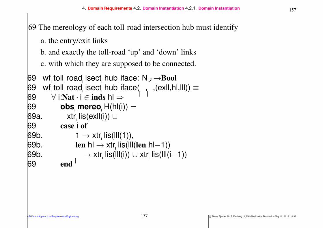
1574. Domain Requirements 4.2. Domain Instantiation 4.2.1. Domain Instantiation
69 The mereology of each toll-road intersection hub must identify
a. the entry/exit links
b. and exactly the toll-road ‘up’ and ‘down’ links
c. with which they are supposed to be connected.
69 wf toll road isect hub iface: NI→Bool
69 wf toll road isect hub iface( , ,(exll,hl,lll)) ≡69 ∀ i:Nat • i ∈ inds hl ⇒69 obs mereo H(hl(i)) =69a. xtr lis(exll(i)) ∪69 case i of
69b. 1 → xtr lis(lll(1)),
69b. len hl → xtr lis(lll(len hl−1))
69b. → xtr lis(lll(i)) ∪ xtr lis(lll(i−1))
69 end
a Different Approach to Requirements Engineering 157 c© Dines Bjørner 2015, Fredsvej 11, DK–2840 Holte, Denmark – May 12, 2016: 10:32

1584. Domain Requirements 4.2. Domain Instantiation 4.2.1. Domain Instantiation
70 The mereology of the entry/exit links must identify exactly the
a. interface hubs and the
b. toll-road intersection hubs
c. with which they are supposed to be connected.
70 wf exll: (L×L)∗×HI∗×H∗→Bool
70 wf exll(exll,hil,hl) ≡70 ∀ i:Nat • i ∈ len exll
70 let (hi,(el,xl),h) = (hil(i),exll(i),hl(i)) in
70 obs mereo L(el) = obs mereo L(xl)
70 = hi ∪ uid H(h) end
70 pre: len eell = len hil = len hl
a Different Approach to Requirements Engineering 158 c© Dines Bjørner 2015, Fredsvej 11, DK–2840 Holte, Denmark – May 12, 2016: 10:32

1594. Domain Requirements 4.2. Domain Instantiation 4.2.1. Domain Instantiation
71 The mereology of the toll-road ‘up’ and ‘down’ links must
a. identify exactly the toll-road intersection hubs
b. with which they are supposed to be connected.
71 wf u d links: (L×L)∗×H∗→Bool
71 wf u d links(lll,hl) ≡71 ∀ i:Nat • i ∈ inds lll ⇒71 let (ul,dl) = lll(i) in
71 obs mereo L(ul) = obs mereo L(dl) =71a. uid H(hl(i)) ∪ uid H(hl(i+1)) end
71 pre: len lll = len hl+1
a Different Approach to Requirements Engineering 159 c© Dines Bjørner 2015, Fredsvej 11, DK–2840 Holte, Denmark – May 12, 2016: 10:32

1604. Domain Requirements 4.2. Domain Instantiation 4.2.1. Domain Instantiation
• We have used some additional auxiliary functions:
xtr his: H∗→HI-set
xtr his(hl) ≡ uid HI(h)|h:H•h ∈ elems hlxtr lis: (L×L)→LI-set
xtr lis(l′
,l′′
) ≡ uid LI(l′
)∪uid LI(l′′
)xtr lis: (L×L)∗− LI-set
xtr lis(lll) ≡∪xtr lis(l
′
,l′′
)|(l′
,l′′
):(L×L)•(l′
,l′′
)∈ elems lll
a Different Approach to Requirements Engineering 160 c© Dines Bjørner 2015, Fredsvej 11, DK–2840 Holte, Denmark – May 12, 2016: 10:32
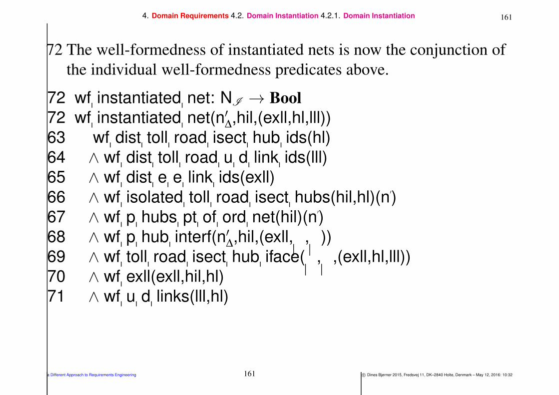
1614. Domain Requirements 4.2. Domain Instantiation 4.2.1. Domain Instantiation
72 The well-formedness of instantiated nets is now the conjunction of
the individual well-formedness predicates above.
72 wf instantiated net: NI → Bool
72 wf instantiated net(n′∆,hil,(exll,hl,lll))
63 wf dist toll road isect hub ids(hl)
64 ∧ wf dist toll road u d link ids(lll)
65 ∧ wf dist e e link ids(exll)
66 ∧ wf isolated toll road isect hubs(hil,hl)(n′
)
67 ∧ wf p hubs pt of ord net(hil)(n′
)
68 ∧ wf p hub interf(n′∆,hil,(exll, , ))
69 ∧ wf toll road isect hub iface( , ,(exll,hl,lll))
70 ∧ wf exll(exll,hil,hl)
71 ∧ wf u d links(lll,hl)
a Different Approach to Requirements Engineering 161 c© Dines Bjørner 2015, Fredsvej 11, DK–2840 Holte, Denmark – May 12, 2016: 10:32
1624. Domain Requirements 4.2. Domain Instantiation 4.2.2. Domain Instantiation — Abstraction
4.2.2. Domain Instantiation — Abstraction
Example 11 Domain Requirements. Instantiation Road Net,
Abstraction:
• Domain instantiation has refined
⋄⋄ an abstract definition of net sorts, nP:NP,
⋄⋄ into a partially concrete definition of nets, nI :NI .
• We need to show the refinement relation:
⋄⋄ abstraction(nI ) = nP.
a Different Approach to Requirements Engineering 162 c© Dines Bjørner 2015, Fredsvej 11, DK–2840 Holte, Denmark – May 12, 2016: 10:32

1634. Domain Requirements 4.2. Domain Instantiation 4.2.2. Domain Instantiation — Abstraction
value
73 abstraction: NI → NP
74 abstraction(n′∆,hil,(exll,hl,lll)) ≡
75 let nP:NP•
75 let hs = obs part HSP(obs part HAP(n′P
)),
75 ls = obs part LSP(obs part LAP(n′P
)),
75 ths = elems hl,
75 eells = xtr links(eell), llls = xtr links(lll) in
76 hs∪ths=obs part HSP(obs part HAP(nP))
77 ∧ ls∪eells∪llls=obs part LSP(obs part LAP(nP))
78 nP end end
a Different Approach to Requirements Engineering 163 c© Dines Bjørner 2015, Fredsvej 11, DK–2840 Holte, Denmark – May 12, 2016: 10:32

1644. Domain Requirements 4.2. Domain Instantiation 4.2.2. Domain Instantiation — Abstraction
73 The abstraction function takes a concrete net, nI :NI , and yields an
abstract net, nP:NP .
74 The abstraction function doubly decomposes its argument into
constituent lists and sub-lists.
75 There is postulated an abstract net, nP:NP , such that
76 the hubs of the concrete net and toll-road equals those of the
abstract net, and
77 the links of the concrete net and toll-road equals those of the
abstract net.
78 And that abstract net, nP:NP , is postulated to be an abstraction of
the concrete net.
a Different Approach to Requirements Engineering 164 c© Dines Bjørner 2015, Fredsvej 11, DK–2840 Holte, Denmark – May 12, 2016: 10:32

1654. Domain Requirements 4.2. Domain Instantiation 4.2.3. Discussion
4.2.3. Discussion
• Domain descriptions, such as illustrated in [Bjø16b, Manifest
Domains: Analysis & Description] and in this paper,
⋄⋄ model families of concrete, i.e., specifically occurring domains.
⋄⋄ Domain instantiation, as exemplified in this section (i.e., Sect. ),
“narrow down” these families.
⋄⋄ Domain instantiation, such as it is defined, cf. Definition 12 on
Slide 147,
allows the requirements engineer to instantiate
to a concrete instance of a very specific domain,
⋄⋄ that, for example, of the toll-road between Bolzano Nord and
Trento Sud in Italy (i.e., n=7)14.
14Here we disregard the fact that this toll-road does not start/end in neither Bolzano Nord nor Trento Sud.
a Different Approach to Requirements Engineering 165 c© Dines Bjørner 2015, Fredsvej 11, DK–2840 Holte, Denmark – May 12, 2016: 10:32

1664. Domain Requirements 4.3. Domain Determination
4.3. Domain Determination
Definition 13 Determination: By domain determination we
mean
• a refinement of the partial domain requirements prescription,
• resulting from the instantiation step,
• in which the refinements aim at rendering the
⋄⋄ endurants:
parts,
materials and
components, as well as the
⋄⋄ perdurants:
functions,
events and
behaviours
of the partial domain requirements prescription
• less non-determinate, more determinate
a Different Approach to Requirements Engineering 166 c© Dines Bjørner 2015, Fredsvej 11, DK–2840 Holte, Denmark – May 12, 2016: 10:32

1674. Domain Requirements 4.3. Domain Determination
• Determinations usually render these concepts less general.
⋄⋄ That is, the value space
of endurants that are made more determinate
is “smaller”, contains fewer values,
as compared to the endurants
before determination has been “applied”.
4.3.1. Domain Determination: Example
• We show an example of ‘domain determination’.
⋄⋄ It is expressed solely in terms of
⋄⋄ axioms over the concrete toll-road net type.
a Different Approach to Requirements Engineering 167 c© Dines Bjørner 2015, Fredsvej 11, DK–2840 Holte, Denmark – May 12, 2016: 10:32

1684. Domain Requirements 4.3. Domain Determination 4.3.1. Domain Determination: Example
Example 12 Domain Requirements. Determination Toll-roads:
• We focus only on the toll-road net.
• We single out only two ’determinations’:
All Toll-road Links are One-way Links
79 The entry/exit and toll-road links
a. are always all one way links,
b. as indicated by the arrows of Fig. 2,
c. such that each pair allows traffic in opposite directions.
a Different Approach to Requirements Engineering 168 c© Dines Bjørner 2015, Fredsvej 11, DK–2840 Holte, Denmark – May 12, 2016: 10:32

1694. Domain Requirements 4.3. Domain Determination 4.3.1. Domain Determination: Example
79 opposite traffics: (L×L)∗ × (L×L)∗ → Bool
79 opposite traffics(exll,lll) ≡79 ∀ (lt,lf):(L×L) • (lt,lf) ∈ elems exll lll ⇒79a. let (ltσ ,lfσ ) = (attr LΣ(lt),attr LΣ(lf)) in
79a.′. attr LΩ(lt)=ltσ∧attr LΩ(ft)=ftσ79a.′′. ∧ card ltσ = 1 = card lfσ79 ∧ let ((hi,hi
′
),(hi′′
,hi′′′
)) = (ltσ ,lfσ ) in
79c. hi=hi′′′
∧ hi′
=hi′′
79 end end
a Different Approach to Requirements Engineering 169 c© Dines Bjørner 2015, Fredsvej 11, DK–2840 Holte, Denmark – May 12, 2016: 10:32

1704. Domain Requirements 4.3. Domain Determination 4.3.1. Domain Determination: Example
All Toll-road Hubs are Free-flow
80 The hub state spaces are singleton sets of the toll-road hub states which
always allow exactly these (and only these) crossings:
a. from entry links back to the paired exit links,
b. from entry links to emanating toll-road links,
c. from incident toll-road links to exit links, and
d. from incident toll-road link to emanating toll-road links.
80 free flow toll road hubs: (L×L)∗×(L×L)∗→Bool
80 free flow toll road hubs(exl,ll) ≡
80 ∀ i:Nat•i ∈ inds hl ⇒
80 attr HΣ(hl(i)) =
80a. hσ ex ls(exl(i))
80b. ∪ hσ et ls(exl(i),(i,ll))
80c. ∪ hσ tx ls(exl(i),(i,ll))
80d. ∪ hσ tt ls(i,ll)
a Different Approach to Requirements Engineering 170 c© Dines Bjørner 2015, Fredsvej 11, DK–2840 Holte, Denmark – May 12, 2016: 10:32

1714. Domain Requirements 4.3. Domain Determination 4.3.1. Domain Determination: Example
80a.: from entry links back to the paired exit links:
80a. hσ ex ls: (L×L)→LΣ
80a. hσ ex ls(e,x) ≡ (uid LI(e),uid LI(x))
a Different Approach to Requirements Engineering 171 c© Dines Bjørner 2015, Fredsvej 11, DK–2840 Holte, Denmark – May 12, 2016: 10:32

1724. Domain Requirements 4.3. Domain Determination 4.3.1. Domain Determination: Example
80b.: from entry links to emanating toll-road links:
80b. hσ et ls: (L×L)×(Nat×(em:L×in:L)∗)→LΣ
80b. hσ et ls((e, ),(i,ll)) ≡80b. case i of
80b. 2 → (uid LI(e),uid LI(em(ll(1)))),
80b. len ll+1 → (uid LI(e),uid LI(em(ll(len ll)))),
80b. → (uid LI(e),uid LI(em(ll(i−1)))),
80b. (uid LI(e),uid LI(em(ll(i))))80b. end
• The em and in in the toll-road link list (em:L×in:L)∗
designate selectors for emanating, respectively incident links.
a Different Approach to Requirements Engineering 172 c© Dines Bjørner 2015, Fredsvej 11, DK–2840 Holte, Denmark – May 12, 2016: 10:32

1734. Domain Requirements 4.3. Domain Determination 4.3.1. Domain Determination: Example
80c.: from incident toll-road links to exit links:
80c. hσ tx ls: (L×L)×(Nat×(em:L×in:L)∗)→LΣ
80c. hσ tx ls(( ,x),(i,ll)) ≡80c. case i of
80c. 2 → (uid LI(in(ll(1))),uid LI(x)),
80c. len ll+1 → (uid LI(in(ll(len ll))),uid LI(x)),
80c. → (uid LI(in(ll(i−1))),uid LI(x)),
80c. (uid LI(in(ll(i))),uid LI(x))80c. end
a Different Approach to Requirements Engineering 173 c© Dines Bjørner 2015, Fredsvej 11, DK–2840 Holte, Denmark – May 12, 2016: 10:32

1744. Domain Requirements 4.3. Domain Determination 4.3.1. Domain Determination: Example
80d.: from incident toll-road link to emanating toll-road links:
80d. hσ tt ls: Nat×(em:L×in:L)∗→LΣ
80d. hσ tt ls(i,ll) ≡80d. case i of
80d. 2 → (uid LI(in(ll(1))),uid LI(em(ll(1)))),
80d. len ll+1 → (uid LI(in(ll(len ll))),uid LI(em(ll(len ll)))),
80d. → (uid LI(in(ll(i−1))),uid LI(em(ll(i−1)))),
80d. (uid LI(in(ll(i))),uid LI(em(ll(i))))80d. end
a Different Approach to Requirements Engineering 174 c© Dines Bjørner 2015, Fredsvej 11, DK–2840 Holte, Denmark – May 12, 2016: 10:32

1754. Domain Requirements 4.3. Domain Determination 4.3.1. Domain Determination: Example
• The example above illustrated ‘domain determination’ with respect
to endurants.
⋄⋄ Typically “endurant determination” is expressed in terms of
axioms that limit state spaces —
⋄⋄ where “endurant instantiation” typically “limited” the mereology
of endurants: how parts are related to one another.
a Different Approach to Requirements Engineering 175 c© Dines Bjørner 2015, Fredsvej 11, DK–2840 Holte, Denmark – May 12, 2016: 10:32

1764. Domain Requirements 4.3. Domain Determination 4.3.1. Domain Determination: Example
• We shall not exemplify domain determination with respect to
perdurants.
a Different Approach to Requirements Engineering 176 c© Dines Bjørner 2015, Fredsvej 11, DK–2840 Holte, Denmark – May 12, 2016: 10:32

1774. Domain Requirements 4.3. Domain Determination 4.3.2. Discussion
4.3.2. Discussion
⋄⋄ The borderline between instantiation and determination is fuzzy.
Whether, as an example, fixing the number of toll-road
intersection hubs to a constant value, e.g., n=7,
is instantiation
or determination,
is really a matter of choice !
a Different Approach to Requirements Engineering 177 c© Dines Bjørner 2015, Fredsvej 11, DK–2840 Holte, Denmark – May 12, 2016: 10:32

1784. Domain Requirements 4.4. Domain Extension
4.4. Domain Extension
Definition 14 Extension: By domain extension we understand
the
• introduction of
⋄⋄ endurants (see Sect. ) and
⋄⋄ perdurants (see Sect. )
that were not feasible in the original domain,
• but for which, with computing and communication,
• and with new, emerging technologies,
• for example, sensors, actuators and satellites,
• there is the possibility of feasible implementations,
• hence the requirements,
• that what is introduced becomes part of the unfolding requirementsprescription
a Different Approach to Requirements Engineering 178 c© Dines Bjørner 2015, Fredsvej 11, DK–2840 Holte, Denmark – May 12, 2016: 10:32
1794. Domain Requirements 4.4. Domain Extension 4.4.1. Endurant Extensions
4.4.1. Endurant Extensions
Definition 15 Endurant Extension:
• By an endurant extension we understand
⋄⋄ the introduction of one or more endurants
⋄⋄ into the projected, instantiated and determined domain DR
⋄⋄ resulting in domain DR′,
⋄⋄ such that these form a conservative extension
⋄⋄ of the theory, TDR
⋄⋄ denoted by the domain requirements DR (i.e., “before” the
extension),
⋄⋄ that is: every theorem of TDR
⋄⋄ is still a theorem of TDR′.
a Different Approach to Requirements Engineering 179 c© Dines Bjørner 2015, Fredsvej 11, DK–2840 Holte, Denmark – May 12, 2016: 10:32
1804. Domain Requirements 4.4. Domain Extension 4.4.1. Endurant Extensions
• Usually domain extensions involve one or more of the already
introduced sorts.
• In Example 13 we introduce (i.e., “extend”)
⋄⋄ vehicles with GPSS-like sensors,
⋄⋄ and introduce toll-gates with
entry sensors,
vehicle identification sensors,
gate actuators and
exit sensors.
⋄⋄ Finally road pricing calculators are introduced.
a Different Approach to Requirements Engineering 180 c© Dines Bjørner 2015, Fredsvej 11, DK–2840 Holte, Denmark – May 12, 2016: 10:32

1814. Domain Requirements 4.4. Domain Extension 4.4.1. Endurant Extensions
Example 13 Domain Requirements — Endurant Extension:
• We present the extensions in several steps.
⋄⋄ Some of them will be developed in this section.
⋄⋄ Development of the remaining will be deferred to Sect. .
⋄⋄ The reason for this deferment is that those last steps are
examples of interface requirements .
a Different Approach to Requirements Engineering 181 c© Dines Bjørner 2015, Fredsvej 11, DK–2840 Holte, Denmark – May 12, 2016: 10:32

1824. Domain Requirements 4.4. Domain Extension 4.4.1. Endurant Extensions
• The initial extension-development steps are:
⋄⋄ [a] vehicle extension,
⋄⋄ [b] sort and unique identifiers of road price calculators,
⋄⋄ [c] vehicle to road pricing calculator channel,
⋄⋄ [d] sorts and dynamic attributes of toll-gates,
⋄⋄ [e] road pricing calculator attributes,
⋄⋄ [f] “total” system state, and
⋄⋄ [g] the overall system behaviour.
• This decomposition establishes system interfaces in “small, easy
steps”.
a Different Approach to Requirements Engineering 182 c© Dines Bjørner 2015, Fredsvej 11, DK–2840 Holte, Denmark – May 12, 2016: 10:32
1834. Domain Requirements 4.4. Domain Extension 4.4.1. Endurant Extensions 4.4.1.1. [a] Vehicle Extension:
4.4.1.1 [a] Vehicle Extension:
81 There is a domain, δE :∆E , which contains
82 a fleet, fE :FE , that is,
83 a set, vsE :VSE , of
84 extended vehicles, vE :VE — their extension amounting to
85 a dynamic reactive attribute, whose value, ti-gpos:TiGpos, at any
time, reflects that vehicle’s time-stamped global position.
86 The vehicle’s GNSS receiver calculates, loc pos, its local position,
lpos:LPos, based on these signals.
87 Vehicles access these external attributes via the external attributechannel, attr TiGPos ch.
a Different Approach to Requirements Engineering 183 c© Dines Bjørner 2015, Fredsvej 11, DK–2840 Holte, Denmark – May 12, 2016: 10:32
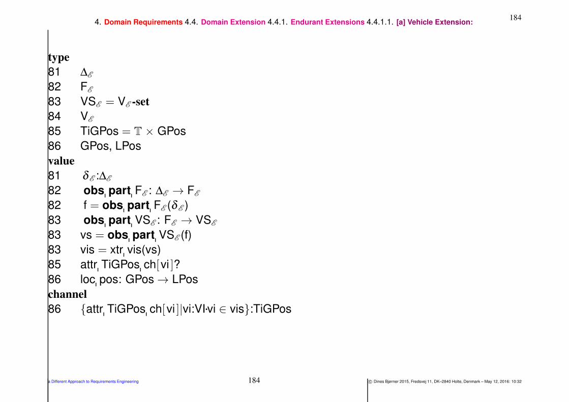
1844. Domain Requirements 4.4. Domain Extension 4.4.1. Endurant Extensions 4.4.1.1. [a] Vehicle Extension:
type
81 ∆E
82 FE
83 VSE = VE -set
84 VE
85 TiGPos = T × GPos
86 GPos, LPos
value
81 δ E :∆E
82 obs part FE : ∆E → FE
82 f = obs part FE (δ E )
83 obs part VSE : FE → VSE
83 vs = obs part VSE (f)
83 vis = xtr vis(vs)
85 attr TiGPos ch[vi ]?
86 loc pos: GPos → LPos
channel
86 attr TiGPos ch[vi ]|vi:VI•vi ∈ vis:TiGPos
a Different Approach to Requirements Engineering 184 c© Dines Bjørner 2015, Fredsvej 11, DK–2840 Holte, Denmark – May 12, 2016: 10:32

1854. Domain Requirements 4.4. Domain Extension 4.4.1. Endurant Extensions 4.4.1.1. [a] Vehicle Extension:
We define two auxiliary functions,
88 xtr vs, which given a domain, or a fleet, extracts its set of vehicles,
and
89 xtr vis which given a set of vehicles generates their unique
identifiers.
value
88 xtr vs: (∆E |FE |VSE ) → VE -set
88 xtr vs(arg) ≡88 is ∆E (arg) → obs part VSE (obs part FE (arg)),
88 is FE (arg) → obs part VSE (arg),
88 is VSE (arg) → arg
89 xtr vis: (∆E |FE |VSE ) → VI-set
89 xtr vis(arg) ≡ uid VI(v)|v ∈ xtr vs(arg)
a Different Approach to Requirements Engineering 185 c© Dines Bjørner 2015, Fredsvej 11, DK–2840 Holte, Denmark – May 12, 2016: 10:32
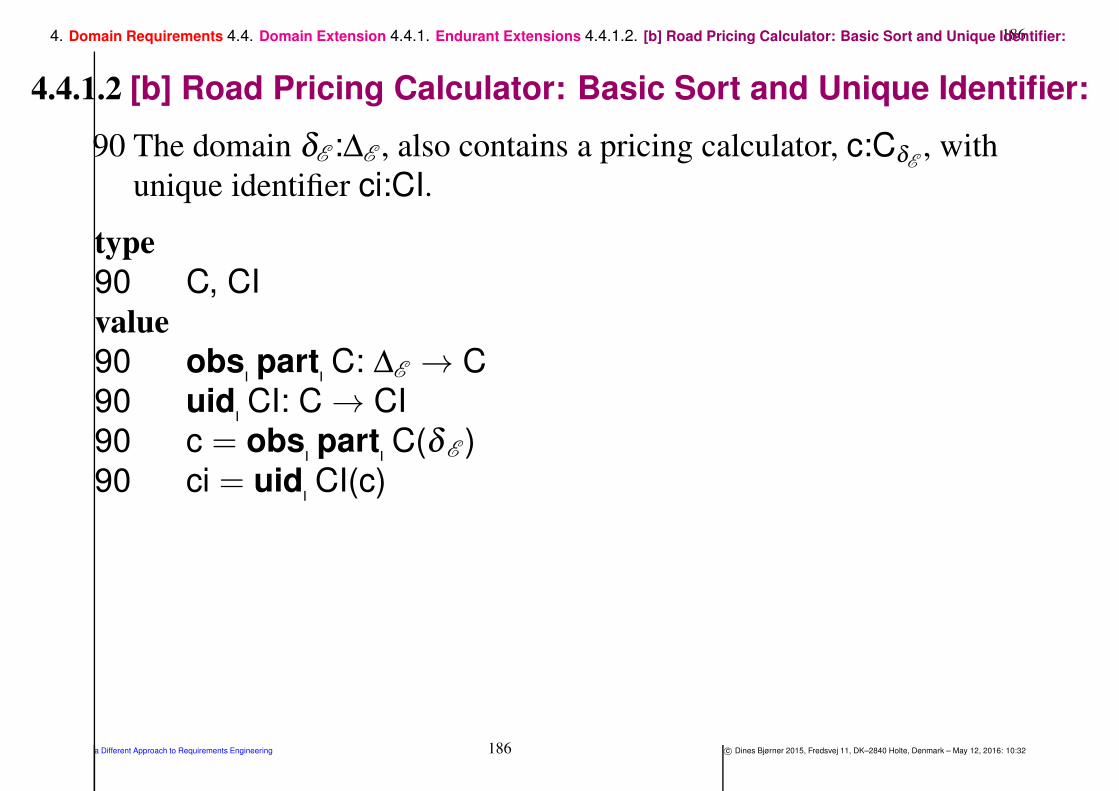
1864. Domain Requirements 4.4. Domain Extension 4.4.1. Endurant Extensions 4.4.1.2. [b] Road Pricing Calculator: Basic Sort and Unique Identifier:
4.4.1.2 [b] Road Pricing Calculator: Basic Sort and Unique Identifier:
90 The domain δE :∆E , also contains a pricing calculator, c:CδE, with
unique identifier ci:CI.
type
90 C, CI
value
90 obs part C: ∆E → C
90 uid CI: C → CI
90 c = obs part C(δ E )
90 ci = uid CI(c)
a Different Approach to Requirements Engineering 186 c© Dines Bjørner 2015, Fredsvej 11, DK–2840 Holte, Denmark – May 12, 2016: 10:32

1874. Domain Requirements 4.4. Domain Extension 4.4.1. Endurant Extensions 4.4.1.3. [c] Vehicle to Road Pricing Calculator Channel:
4.4.1.3 [c] Vehicle to Road Pricing Calculator Channel:
91 Vehicles can, on their own volition, offer the timed local position,
viti-lpos:VITiLPos
92 to the pricing calculator, c:CE along a vehicles-to-calculator
channel, v c ch.
type
91 VITiLPos = VI × (T × LPos)
channel
92 v c ch[vi,ci ]|vi:VI,ci:CI•vi∈vis∧ci=uid C(c):VITiLPos
a Different Approach to Requirements Engineering 187 c© Dines Bjørner 2015, Fredsvej 11, DK–2840 Holte, Denmark – May 12, 2016: 10:32
1884. Domain Requirements 4.4. Domain Extension 4.4.1. Endurant Extensions 4.4.1.4. [d] Toll-gate Sorts and Dynamic Types:
4.4.1.4 [d] Toll-gate Sorts and Dynamic Types:
• We extend the domain with toll-gates for vehicles
entering and exiting the toll-road entry and exit links.
• Figure 2 illustrates the idea of gates.
a Different Approach to Requirements Engineering 188 c© Dines Bjørner 2015, Fredsvej 11, DK–2840 Holte, Denmark – May 12, 2016: 10:32
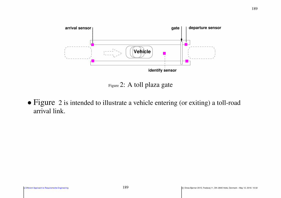
189
gate
Vehicle
identify sensor
arrival sensor departure sensor
Figure 2: A toll plaza gate
• Figure 2 is intended to illustrate a vehicle entering (or exiting) a toll-road
arrival link.
a Different Approach to Requirements Engineering 189 c© Dines Bjørner 2015, Fredsvej 11, DK–2840 Holte, Denmark – May 12, 2016: 10:32

1904. Domain Requirements 4.4. Domain Extension 4.4.1. Endurant Extensions 4.4.1.4. [d] Toll-gate Sorts and Dynamic Types:
⋄⋄ The toll-gate is equipped with three sensors:
an arrival sensor, a vehicle identification sensor and an departure
sensor.
⋄⋄ The arrival sensor serves to prepare
the vehicle identification sensor.
⋄⋄ The departure sensor serves to prepare
the gate for closing when a vehicle has passed.
⋄⋄ The vehicle identify sensor identifies the vehicle and “delivers” a
pair: the current time and the vehicle identifier.
⋄⋄ Once the vehicle identification sensor has identified a vehicle
the gate opens and
a message is sent to the road pricing calculator as to the
passing vehicle’s identity and the identity of the link
associated with the toll-gate (see Items 109- 110 on Slide 197).
a Different Approach to Requirements Engineering 190 c© Dines Bjørner 2015, Fredsvej 11, DK–2840 Holte, Denmark – May 12, 2016: 10:32
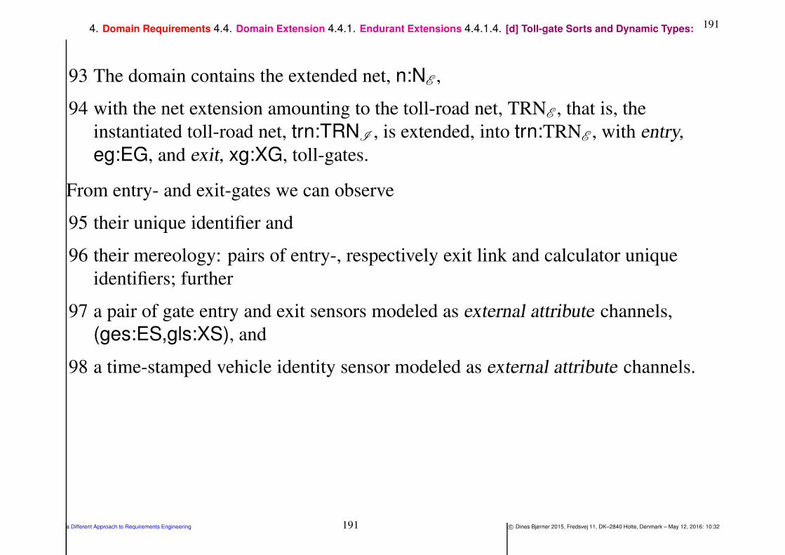
1914. Domain Requirements 4.4. Domain Extension 4.4.1. Endurant Extensions 4.4.1.4. [d] Toll-gate Sorts and Dynamic Types:
93 The domain contains the extended net, n:NE ,
94 with the net extension amounting to the toll-road net, TRNE , that is, the
instantiated toll-road net, trn:TRNI , is extended, into trn:TRNE , with entry,
eg:EG, and exit, xg:XG, toll-gates.
From entry- and exit-gates we can observe
95 their unique identifier and
96 their mereology: pairs of entry-, respectively exit link and calculator unique
identifiers; further
97 a pair of gate entry and exit sensors modeled as external attribute channels,
(ges:ES,gls:XS), and
98 a time-stamped vehicle identity sensor modeled as external attribute channels.
a Different Approach to Requirements Engineering 191 c© Dines Bjørner 2015, Fredsvej 11, DK–2840 Holte, Denmark – May 12, 2016: 10:32

1924. Domain Requirements 4.4. Domain Extension 4.4.1. Endurant Extensions 4.4.1.4. [d] Toll-gate Sorts and Dynamic Types:
type
93 NE
94 TRNE = (EG×XG)∗ × TRNI
95 GI
value
93 obs part NE : ∆E → NE
94 obs part TRNE : NE → TRNE
95 uid G: (EG|XG) → GI
96 obs mereo G: (EG|XG) → (LI×CI)
94 trn:TRNE = obs part TRNE (δ E )
channel
97 attr entry ch[gi ]|gi:GI•xtr eGIds(trn)′′
enter′′
97 attr exit ch[gi ]|gi:GI•xtr xGIds(trn)′′
exit′′
98 attr identity ch[gi ]|gi:GI•xtr GIds(trn) TIVI
type
98 TIVI = T × VI
a Different Approach to Requirements Engineering 192 c© Dines Bjørner 2015, Fredsvej 11, DK–2840 Holte, Denmark – May 12, 2016: 10:32
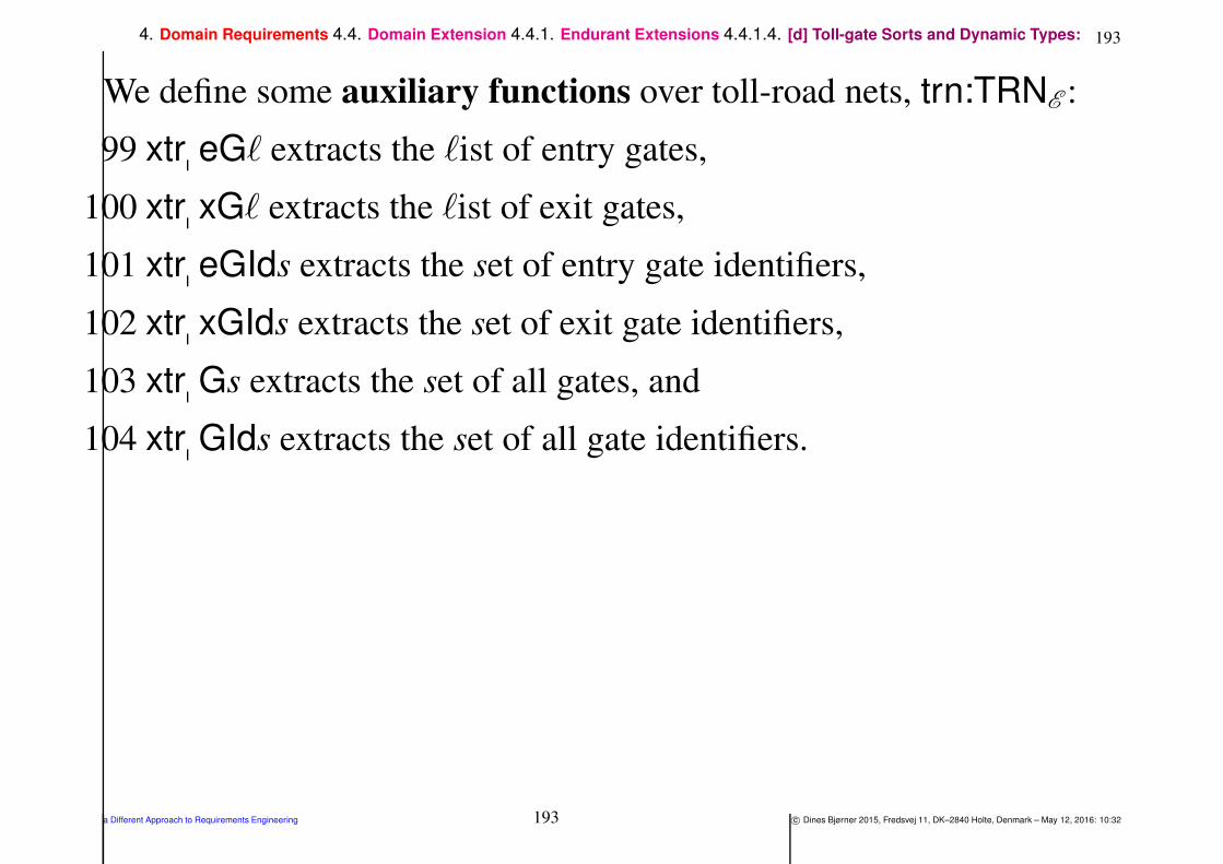
1934. Domain Requirements 4.4. Domain Extension 4.4.1. Endurant Extensions 4.4.1.4. [d] Toll-gate Sorts and Dynamic Types:
We define some auxiliary functions over toll-road nets, trn:TRNE :
99 xtr eGℓ extracts the ℓist of entry gates,
100 xtr xGℓ extracts the ℓist of exit gates,
101 xtr eGIds extracts the set of entry gate identifiers,
102 xtr xGIds extracts the set of exit gate identifiers,
103 xtr Gs extracts the set of all gates, and
104 xtr GIds extracts the set of all gate identifiers.
a Different Approach to Requirements Engineering 193 c© Dines Bjørner 2015, Fredsvej 11, DK–2840 Holte, Denmark – May 12, 2016: 10:32

1944. Domain Requirements 4.4. Domain Extension 4.4.1. Endurant Extensions 4.4.1.4. [d] Toll-gate Sorts and Dynamic Types:
value
99 xtr eGℓ: TRNE → EG∗
99 xtr eGℓ(pgl, ) ≡ eg|(eg,xg):(EG,XG)•(eg,xg)∈ elems pgl100 xtr xGℓ: TRNE → XG∗
100 xtr xGℓ(pgl, ) ≡ xg|(eg,xg):(EG,XG)•(eg,xg)∈ elems pgl101 xtr eGIds: TRNE → GI-set
101 xtr eGIds(pgl, ) ≡ uid GI(g)|g:EG•g ∈ xtr eGs(pgl, )102 xtr xGIds: TRNE → GI-set
102 xtr xGIds(pgl, ) ≡ uid GI(g)|g:EG•g ∈ xtr xGs(pgl, )103 xtr Gs: TRNE → G-set
103 xtr Gs(pgl, ) ≡ xtr eGs(pgl, ) ∪ xtr xGs(pgl, )
104 xtr GIds: TRNE → GI-set
104 xtr GIds(pgl, ) ≡ xtr eGIds(pgl, ) ∪ xtr xGIds(pgl, )
a Different Approach to Requirements Engineering 194 c© Dines Bjørner 2015, Fredsvej 11, DK–2840 Holte, Denmark – May 12, 2016: 10:32

1954. Domain Requirements 4.4. Domain Extension 4.4.1. Endurant Extensions 4.4.1.4. [d] Toll-gate Sorts and Dynamic Types:
105 A well-formedness condition expresses
a. that there are as many entry end exit gate pairs as there are
toll-plazas,
b. that all gates are uniquely identified, and
c. that each entry [exit] gate is paired with an entry [exit] link and
has that link’s unique identifier as one element of its mereology,
the other elements being the calculator identifier and the vehicle
identifiers.
The well-formedness relies on awareness of
106 the unique identifier, ci:CI, of the road pricing calculator, c:C, and
107 the unique identifiers, vis:VI-set, of the fleet vehicles.
a Different Approach to Requirements Engineering 195 c© Dines Bjørner 2015, Fredsvej 11, DK–2840 Holte, Denmark – May 12, 2016: 10:32

1964. Domain Requirements 4.4. Domain Extension 4.4.1. Endurant Extensions 4.4.1.4. [d] Toll-gate Sorts and Dynamic Types:
axiom
105 ∀ n:NR3, trn:TRNR3
•
105 let (exgl,(exl,hl,lll)) = obs part TRNR3(n) in
105a. len exgl = len exl = len hl = len lll + 1
105b. ∧ card xtr GIds(exgl) = 2 ∗ len exgl
105c. ∧ ∀ i:Nat•i ∈ inds exgl•
105c. let ((eg,xg),(el,xl)) = (exgl(i),exl(i)) in
105c. obs mereo G(eg) = (uid U(el),ci,vis)
105c. ∧ obs mereo G(xg) = (uid U(xl),ci,vis)
105 end end
a Different Approach to Requirements Engineering 196 c© Dines Bjørner 2015, Fredsvej 11, DK–2840 Holte, Denmark – May 12, 2016: 10:32
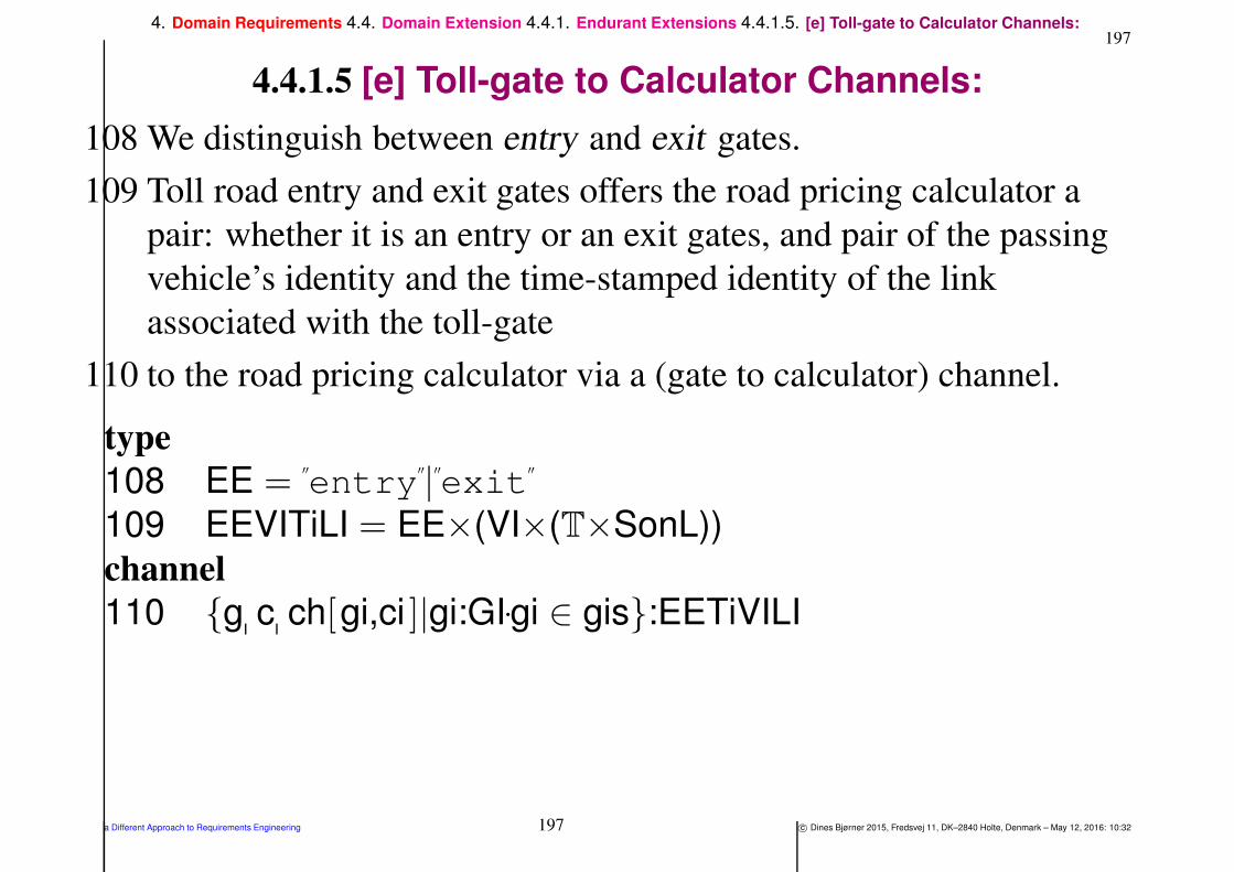
1974. Domain Requirements 4.4. Domain Extension 4.4.1. Endurant Extensions 4.4.1.5. [e] Toll-gate to Calculator Channels:
4.4.1.5 [e] Toll-gate to Calculator Channels:
108 We distinguish between entry and exit gates.
109 Toll road entry and exit gates offers the road pricing calculator a
pair: whether it is an entry or an exit gates, and pair of the passing
vehicle’s identity and the time-stamped identity of the link
associated with the toll-gate
110 to the road pricing calculator via a (gate to calculator) channel.
type
108 EE =′′
entry′′
|′′
exit′′
109 EEVITiLI = EE×(VI×(T×SonL))
channel
110 g c ch[gi,ci ]|gi:GI•gi ∈ gis:EETiVILI
a Different Approach to Requirements Engineering 197 c© Dines Bjørner 2015, Fredsvej 11, DK–2840 Holte, Denmark – May 12, 2016: 10:32
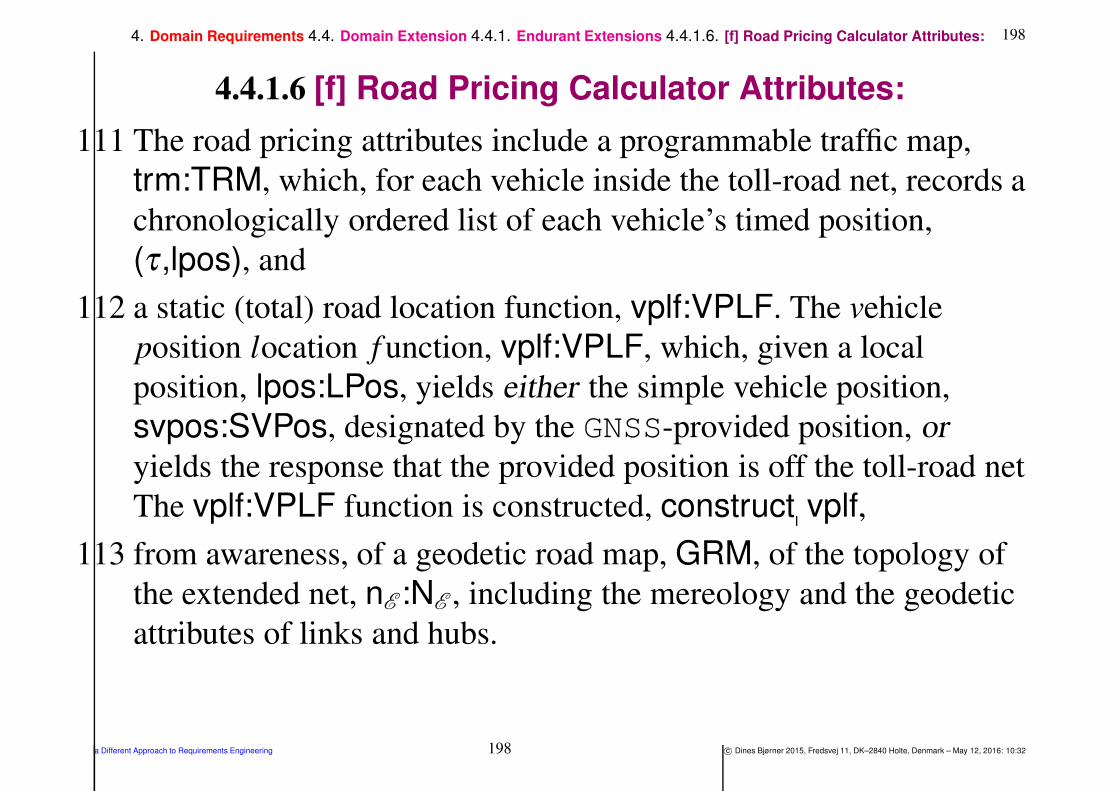
1984. Domain Requirements 4.4. Domain Extension 4.4.1. Endurant Extensions 4.4.1.6. [f] Road Pricing Calculator Attributes:
4.4.1.6 [f] Road Pricing Calculator Attributes:
111 The road pricing attributes include a programmable traffic map,
trm:TRM, which, for each vehicle inside the toll-road net, records a
chronologically ordered list of each vehicle’s timed position,
(τ ,lpos), and
112 a static (total) road location function, vplf:VPLF. The vehicle
position location f unction, vplf:VPLF, which, given a local
position, lpos:LPos, yields either the simple vehicle position,
svpos:SVPos, designated by the GNSS-provided position, oryields the response that the provided position is off the toll-road net
The vplf:VPLF function is constructed, construct vplf,
113 from awareness, of a geodetic road map, GRM, of the topology of
the extended net, nE :NE , including the mereology and the geodetic
attributes of links and hubs.
a Different Approach to Requirements Engineering 198 c© Dines Bjørner 2015, Fredsvej 11, DK–2840 Holte, Denmark – May 12, 2016: 10:32

1994. Domain Requirements 4.4. Domain Extension 4.4.1. Endurant Extensions 4.4.1.6. [f] Road Pricing Calculator Attributes:
type
111 TRM = VI →m (T × SVPos)∗
112 VPLF = GRM → LPos → (SVPos |′′
off_N′′
)
113 GRM
value
111 attr TRM: CE → TRM
112 attr VPLF: CE → VPLF
a Different Approach to Requirements Engineering 199 c© Dines Bjørner 2015, Fredsvej 11, DK–2840 Holte, Denmark – May 12, 2016: 10:32

2004. Domain Requirements 4.4. Domain Extension 4.4.1. Endurant Extensions 4.4.1.6. [f] Road Pricing Calculator Attributes:
• The geodetic road map maps geodetic locations into hub and link
identifiers.
23 Geodetic link locations represent the set of point locations of a link.
19a. Geodetic hub locations represent the set of point locations of a hub.
114 A geodetic road map maps geodetic link locations into link
identifiers and geodetic hub locations into hub identifiers.
115 We sketch the construction, geo GRM, of geodetic road maps.
a Different Approach to Requirements Engineering 200 c© Dines Bjørner 2015, Fredsvej 11, DK–2840 Holte, Denmark – May 12, 2016: 10:32

2014. Domain Requirements 4.4. Domain Extension 4.4.1. Endurant Extensions 4.4.1.6. [f] Road Pricing Calculator Attributes:
type
114 GRM = (GeoL →m LI)⋃
(GeoH →m HI)
value
115 geo GRM: N → GRM
115 geo GRM(n) ≡115 let ls = xtr links(n), hs = xtr hubs(n) in
115 [attr GeoL(l) 7→uid LI(l)|l:L•l ∈ ls ]115 ∪115 [attr GeoH(h) 7→uid HI(h)|h:H•h ∈ hs ] end
a Different Approach to Requirements Engineering 201 c© Dines Bjørner 2015, Fredsvej 11, DK–2840 Holte, Denmark – May 12, 2016: 10:32

2024. Domain Requirements 4.4. Domain Extension 4.4.1. Endurant Extensions 4.4.1.6. [f] Road Pricing Calculator Attributes:
116 The vplf:VPLF function obtains a simple vehicle position, svpos,
from a geodetic road map, grm:GRM, and a local position , lpos:
value
116 obtain SVPos: GRM → LPos → SVPos
116 obtain SVPos(grm)(lpos) as svpos
116 post: case svpos of
116 SatH(hi) → within(lpos,grm(hi)),
116 SonL(li) → within(lpos,grm(li)),
116′′
off_N′′
→ true end
a Different Approach to Requirements Engineering 202 c© Dines Bjørner 2015, Fredsvej 11, DK–2840 Holte, Denmark – May 12, 2016: 10:32

2034. Domain Requirements 4.4. Domain Extension 4.4.1. Endurant Extensions 4.4.1.7. [g] “Total” System State:
4.4.1.7 [g] “Total” System State:
Global values:
117 There is a given domain, δE :∆E ;
118 there is the net, nE :NE , of that domain;
119 there is toll-road net, trnE :TRNE , of that net;
120 there is a set, egsE :EGE -set, of entry gates;
121 there is a set, xgsE :XGE -set, of exit gates;
122 there is a set, gisE :GIE -set, ofgate identifiers;
123 there is a set, vsE :VE -set, of vehicles;
124 there is a set, visE :VIE -set, of vehicle identifiers;
125 there is the road-pricing calculator, cE :CE and
126 there is its unique identifier, ciE :CI.
a Different Approach to Requirements Engineering 203 c© Dines Bjørner 2015, Fredsvej 11, DK–2840 Holte, Denmark – May 12, 2016: 10:32

2044. Domain Requirements 4.4. Domain Extension 4.4.1. Endurant Extensions 4.4.1.7. [g] “Total” System State:
value
117 δ E :∆E
118 nE :NE = obs part NE (δ E )
119 trnE :TRNE = obs part TRNE (nE )
120 egsE :EG-set = xtr egs(trnE )
121 xgsE :XG-set = xtr xgs(trnE )
122 gisE :XG-set = xtr gis(trnE )
123 vsE :VE -set = obs part VS(obs part FE (δE ))124 visE :VI-set = uid VI(vE )|vE :VE
•vE ∈ vsE 125 cE :CE = obs part CE (δ E )
126 ciE :CIE = uid CI(cE )
a Different Approach to Requirements Engineering 204 c© Dines Bjørner 2015, Fredsvej 11, DK–2840 Holte, Denmark – May 12, 2016: 10:32
2054. Domain Requirements 4.4. Domain Extension 4.4.1. Endurant Extensions 4.4.1.8. [h] “Total” System Behaviour:
4.4.1.8 [h] “Total” System Behaviour:
The signature and definition of the system behaviour is sketched as are
the signatures of the vehicle, toll-gate and road pricing calculator.
• We shall model the behaviour of the road pricing system as
follows:
⋄⋄ we shall not model behaviours nets, hubs and links;
⋄⋄ thus we shall model only
the behaviour of vehicles, veh,
the behaviour of toll-gates, gate, and
the behaviour of the road-pricing calculator, calc,
⋄⋄ The behaviours of vehicles and toll-gates are presented here.
⋄⋄ But the behaviour of the road-pricing calculator is “deferred” till
Sect. 5.4 since it reflects an interface requirements.
a Different Approach to Requirements Engineering 205 c© Dines Bjørner 2015, Fredsvej 11, DK–2840 Holte, Denmark – May 12, 2016: 10:32
2064. Domain Requirements 4.4. Domain Extension 4.4.1. Endurant Extensions 4.4.1.8. [h] “Total” System Behaviour:
127 The road pricing system behaviour, sys, is expressed as
a. the parallel, ‖, (distributed) composition of the behaviours of all
vehicles,
b. with the parallel composition of the parallel (likewise
distributed) composition of the behaviours of all entry gates,
c. with the parallel composition of the parallel (likewise
distributed) composition of the behaviours of all exit gates,
d. with the parallel composition of the behaviour of the
road-pricing calculator,
a Different Approach to Requirements Engineering 206 c© Dines Bjørner 2015, Fredsvej 11, DK–2840 Holte, Denmark – May 12, 2016: 10:32

2074. Domain Requirements 4.4. Domain Extension 4.4.1. Endurant Extensions 4.4.1.8. [h] “Total” System Behaviour:
value
127 sys: Unit → Unit
127 sys() ≡
127a. ‖ veh(uid V(v),(ci,gis))|v:V•v ∈ vsE
127b. ‖ ‖ gate(gi,”entry”,obs mereo G(eg))|eg:EG•eg ∈ egsE∧gi=uid EG(eg)
127c. ‖ ‖ gate(gi,”exit”,obs mereo G(xg))|xg:XG•xg ∈ xgsE∧gi=uid XG(xg)
127d. ‖ calc(ciE ,(visE ,gisE ))(rlf)(trm)
128 veh: vi:VI×(ci:CI×gis:GI-set) → out v c ch[vi,ci ] Unit
134 gate: gi:GI×ee:EE×(ci:CI×VI-set×LI) → in attr entry ch[gi,ci ],attr id ch[gi,ci ],attr exit ch[gi,ci ] out
168 calc: ci:CI×(vis:VI-set×gis:GI-set)×VPLF→TRM→ in v c ch[vi,ci ]|vi:VI•vi ∈ vis,g c ch[gi,ci ]|gi:GI
• We consider ”entry” or ”exit” to be a static attribute of toll-gates.
• The behaviour signatures were determined as per the techniques presented in [Bjø16b, Sect. 4.1.1
and 4.5.2].
a Different Approach to Requirements Engineering 207 c© Dines Bjørner 2015, Fredsvej 11, DK–2840 Holte, Denmark – May 12, 2016: 10:32

2084. Domain Requirements 4.4. Domain Extension 4.4.1. Endurant Extensions 4.4.1.8. [h] “Total” System Behaviour:
Vehicle Behaviour:
128 Instead of moving around by explicitly expressed internal
non-determinism15 vehicles move around by unstated internal
non-determinism and instead receive their current position from the
global positioning subsystem.
129 At each moment the vehicle receives its time-stamped global
position, (τ ,gpos):TiGPos,
130 from which it calculates the local position, lpos:VPos
131 which it then communicates, with its vehicle identification,
(vi,(τ ,lpos)), to the road pricing subsystem —
132 whereupon it resumes its vehicle behaviour.
15We refer to Items 46b., 46c. on Slide 68 and 47b., 47(b.)ii, 47c. on Slide 70
a Different Approach to Requirements Engineering 208 c© Dines Bjørner 2015, Fredsvej 11, DK–2840 Holte, Denmark – May 12, 2016: 10:32

2094. Domain Requirements 4.4. Domain Extension 4.4.1. Endurant Extensions 4.4.1.8. [h] “Total” System Behaviour:
value
128 veh: vi:VI×(ci:CI×gis:GI-set) →128 in attr TiGPos ch[vi ] out v c ch[vi,ci ] Unit
128 veh(vi,(ci,gis)) ≡129 let (τ ,gpos) = attr TiGPos ch[vi ]? in
130 let lpos = loc pos(gpos) in
131 v c ch[vi,ci ] ! (vi,(τ ,lpos)) ;
132 veh(vi,(ci,gis)) end end
128 pre vi ∈ visE ∧ ci = ciE ∧ gis = gisE
a Different Approach to Requirements Engineering 209 c© Dines Bjørner 2015, Fredsvej 11, DK–2840 Holte, Denmark – May 12, 2016: 10:32

2104. Domain Requirements 4.4. Domain Extension 4.4.1. Endurant Extensions 4.4.1.8. [h] “Total” System Behaviour:
• The above behaviour represents an assumption
about the behaviour of vehicles.
⋄⋄ If we were to design software for the monitoring and control
of vehicles
⋄⋄ then the above vehicle behaviour would have to be refined in
order to serve as a proper interface requirements.
⋄⋄ The refinement would include handling concerns
about the drivers’ behaviour when entering, passing and
exiting toll-gates,
about the proper function of the GNSS equipment, and
about the safe communication with the road price calculator.
a Different Approach to Requirements Engineering 210 c© Dines Bjørner 2015, Fredsvej 11, DK–2840 Holte, Denmark – May 12, 2016: 10:32

2114. Domain Requirements 4.4. Domain Extension 4.4.1. Endurant Extensions 4.4.1.8. [h] “Total” System Behaviour:
⋄⋄ The above concerns would already have been addressed
in a model of domain facets such as
∗ human behaviour,
∗ technology support,
∗ proper tele-communications scripts,
∗ etcetera.
We refer to [Bjø10a].
a Different Approach to Requirements Engineering 211 c© Dines Bjørner 2015, Fredsvej 11, DK–2840 Holte, Denmark – May 12, 2016: 10:32

2124. Domain Requirements 4.4. Domain Extension 4.4.1. Endurant Extensions 4.4.1.8. [h] “Total” System Behaviour:
Gate Behaviour:
• The entry and the exit gates have “vehicle enter”, “vehicle exit” and
“timed vehicle identification” sensors.
⋄⋄ The following assumption can now be made:
during the time interval between
a gate’s vehicle “entry” sensor having first sensed a vehicle
entering that gate
and that gate’s “exit” sensor having last sensed that vehicle
leaving that gate
that gate’s vehicle time and “identify” sensor registers the time
when the vehicle is entering the gate and that vehicle’s unique
identification.
a Different Approach to Requirements Engineering 212 c© Dines Bjørner 2015, Fredsvej 11, DK–2840 Holte, Denmark – May 12, 2016: 10:32

2134. Domain Requirements 4.4. Domain Extension 4.4.1. Endurant Extensions 4.4.1.8. [h] “Total” System Behaviour:
• We sketch the toll-gate behaviour:
133 We parameterise the toll-gate behaviour as either an entry or an exit gate.
134 Toll-gates operate autonomously and cyclically.
135 The attr enter ch event “triggers” the behaviour specified in formula line Item
136–138 starting with a ”Raise” barrier action.
136 The time-of-passing and the identity of the passing vehicle is sensed by
attr passing ch channel events.
137 Then the road pricing calculator is informed of time-of-passing and of the
vehicle identity vi and the link li associated with the gate – and with a ”Lower”
barrier action.
138 And finally, after that vehicle has left the entry or exit gate the barrier is again
”Lower”ered and
139 that toll-gate’s behaviour is resumed.
a Different Approach to Requirements Engineering 213 c© Dines Bjørner 2015, Fredsvej 11, DK–2840 Holte, Denmark – May 12, 2016: 10:32

2144. Domain Requirements 4.4. Domain Extension 4.4.1. Endurant Extensions 4.4.1.8. [h] “Total” System Behaviour:
type
133 EE =′′
enter′′
|′′
exit′′
value
134 gate: gi:GI×ee:EE×(ci:CI×VI-set×LI) →134 in attr enter ch[gi ],attr passing ch[gi ],attr leave ch[gi ]134 out attr barrier ch[gi ],g c ch[gi,ci ] Unit
134 gate(gi,ee,(ci,vis,li)) ≡135 attr enter ch[gi ] ? ; attr barrier ch[gi ] ! ”Lower”
136 let (τ ,vi) = attr passing ch[gi ] ? in assert vi ∈ vis
137 (attr barrier ch[gi ] ! ”Raise” ‖ g c ch[gi,ci ] ! (ee,(vi,(τ ,SonL(li))))) ;
138 attr leave ch[gi ] ? ; attr barrier ch[gi ] ! ”Lower”
139 gate(gi,ee,(ci,vis,li))
134 end
134 pre ci = ciE ∧ vis = visE ∧ li ∈ lisE
a Different Approach to Requirements Engineering 214 c© Dines Bjørner 2015, Fredsvej 11, DK–2840 Holte, Denmark – May 12, 2016: 10:32

2154. Domain Requirements 4.4. Domain Extension 4.4.1. Endurant Extensions 4.4.1.8. [h] “Total” System Behaviour:
• The gate signature’s attr enter ch[gi ], attr passing ch[gi ],attr barrier ch[gi ] and attr leave ch[gi ] model respective externalattributes [Bjø16b, Sect. 4.1.1 and 4.5.2] (the attr barrier ch[gi ]models reactive (i.e., output) attribute), while
• g c ch[gi,ci ] models the embedded attribute sharing between gates
(their identification of vehicle positions) and the calculator road
map.
a Different Approach to Requirements Engineering 215 c© Dines Bjørner 2015, Fredsvej 11, DK–2840 Holte, Denmark – May 12, 2016: 10:32

2164. Domain Requirements 4.4. Domain Extension 4.4.1. Endurant Extensions 4.4.1.8. [h] “Total” System Behaviour:
• The above behaviour represents an assumption
about the behaviour of toll-gates.
⋄⋄ If we were to design software for the monitoring and control
of toll-gates
⋄⋄ then the above gate behaviour would have to be refined in order
to serve as a proper interface requirements.
⋄⋄ The refinement would include handling concerns
about the drivers’ behaviour when entering, passing and
exiting toll-gates,
about the proper function of the entry, passing and exit sensors,
about the proper function of the gate barrier (opening and
closing), and
about the safe communication with the road price calculator.
a Different Approach to Requirements Engineering 216 c© Dines Bjørner 2015, Fredsvej 11, DK–2840 Holte, Denmark – May 12, 2016: 10:32

2174. Domain Requirements 4.4. Domain Extension 4.4.1. Endurant Extensions 4.4.1.8. [h] “Total” System Behaviour:
The above concerns would already have been addressed
• in a model of domain facets such as
⋄⋄ human behaviour,
⋄⋄ technology support,
⋄⋄ proper tele-communications scripts,
⋄⋄ etcetera.
• We refer to [Bjø10a]
a Different Approach to Requirements Engineering 217 c© Dines Bjørner 2015, Fredsvej 11, DK–2840 Holte, Denmark – May 12, 2016: 10:32

2184. Domain Requirements 4.5. Requirements Fitting
4.5. Requirements Fitting
• Often a domain being described
• “fits” onto, is “adjacent” to, “interacts” in some areas with,
• another domain:
⋄⋄ transportation with logistics,
⋄⋄ health-care with insurance,
⋄⋄ banking with securities trading and/or insurance,
⋄⋄ and so on.
a Different Approach to Requirements Engineering 218 c© Dines Bjørner 2015, Fredsvej 11, DK–2840 Holte, Denmark – May 12, 2016: 10:32
2194. Domain Requirements 4.5. Requirements Fitting
• The issue of requirements fitting arises
⋄⋄ when two or more software development projects
⋄⋄ are based on what appears to be the same domain.
• The problem then is
⋄⋄ to harmonise the two or more software development projects
⋄⋄ by harmonising, if not too late, their requirements developments.
a Different Approach to Requirements Engineering 219 c© Dines Bjørner 2015, Fredsvej 11, DK–2840 Holte, Denmark – May 12, 2016: 10:32
2204. Domain Requirements 4.5. Requirements Fitting
• We thus assume
⋄⋄ that there are n domain requirements developments,
dr1, dr2
, . . . , drn, being considered, and
⋄⋄ that these pertain to the same domain — and can hence be
assumed covered by a same domain description.
a Different Approach to Requirements Engineering 220 c© Dines Bjørner 2015, Fredsvej 11, DK–2840 Holte, Denmark – May 12, 2016: 10:32
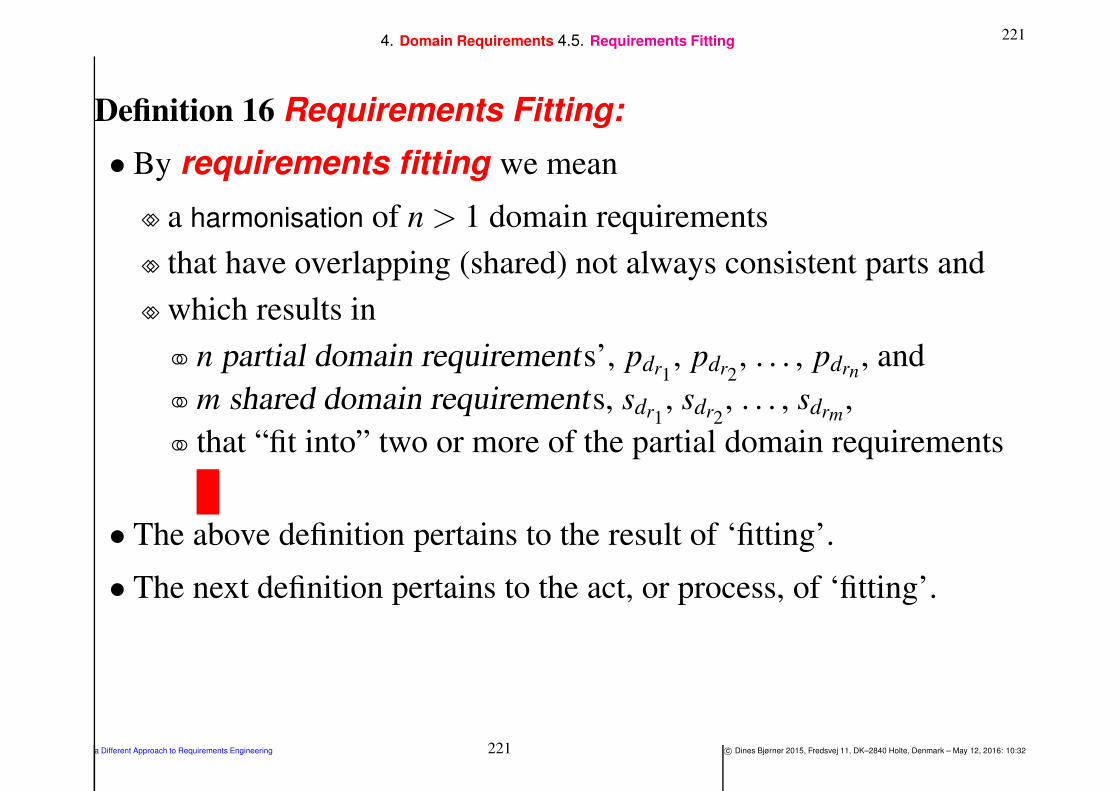
2214. Domain Requirements 4.5. Requirements Fitting
Definition 16 Requirements Fitting:
• By requirements fitting we mean
⋄⋄ a harmonisation of n > 1 domain requirements
⋄⋄ that have overlapping (shared) not always consistent parts and
⋄⋄ which results in
n partial domain requirements’, pdr1, pdr2
, . . . , pdrn, and
m shared domain requirements, sdr1, sdr2
, . . . , sdrm,
that “fit into” two or more of the partial domain requirements
• The above definition pertains to the result of ‘fitting’.
• The next definition pertains to the act, or process, of ‘fitting’.
a Different Approach to Requirements Engineering 221 c© Dines Bjørner 2015, Fredsvej 11, DK–2840 Holte, Denmark – May 12, 2016: 10:32

2224. Domain Requirements 4.5. Requirements Fitting
Definition 17 Requirements Harmonisation:
• By requirements harmonisation we mean
⋄⋄ a number of alternative
and/or co-ordinated prescription actions,
⋄⋄ one set for each of the domain requirements actions:
Projection,
Instantiation,
Determination and
Extension.
a Different Approach to Requirements Engineering 222 c© Dines Bjørner 2015, Fredsvej 11, DK–2840 Holte, Denmark – May 12, 2016: 10:32

2234. Domain Requirements 4.5. Requirements Fitting
• They are – we assume n separate software product requirements:
⋄⋄ Projection:
If the n product requirements
do not have the same projections,
then identify a common projection which they all share,
and refer to it as the common projection .
Then develop, for each of the n product requirements,
if required,
a specific projection of the common one.
Let there be m such specific projections, m ≤ n.
a Different Approach to Requirements Engineering 223 c© Dines Bjørner 2015, Fredsvej 11, DK–2840 Holte, Denmark – May 12, 2016: 10:32
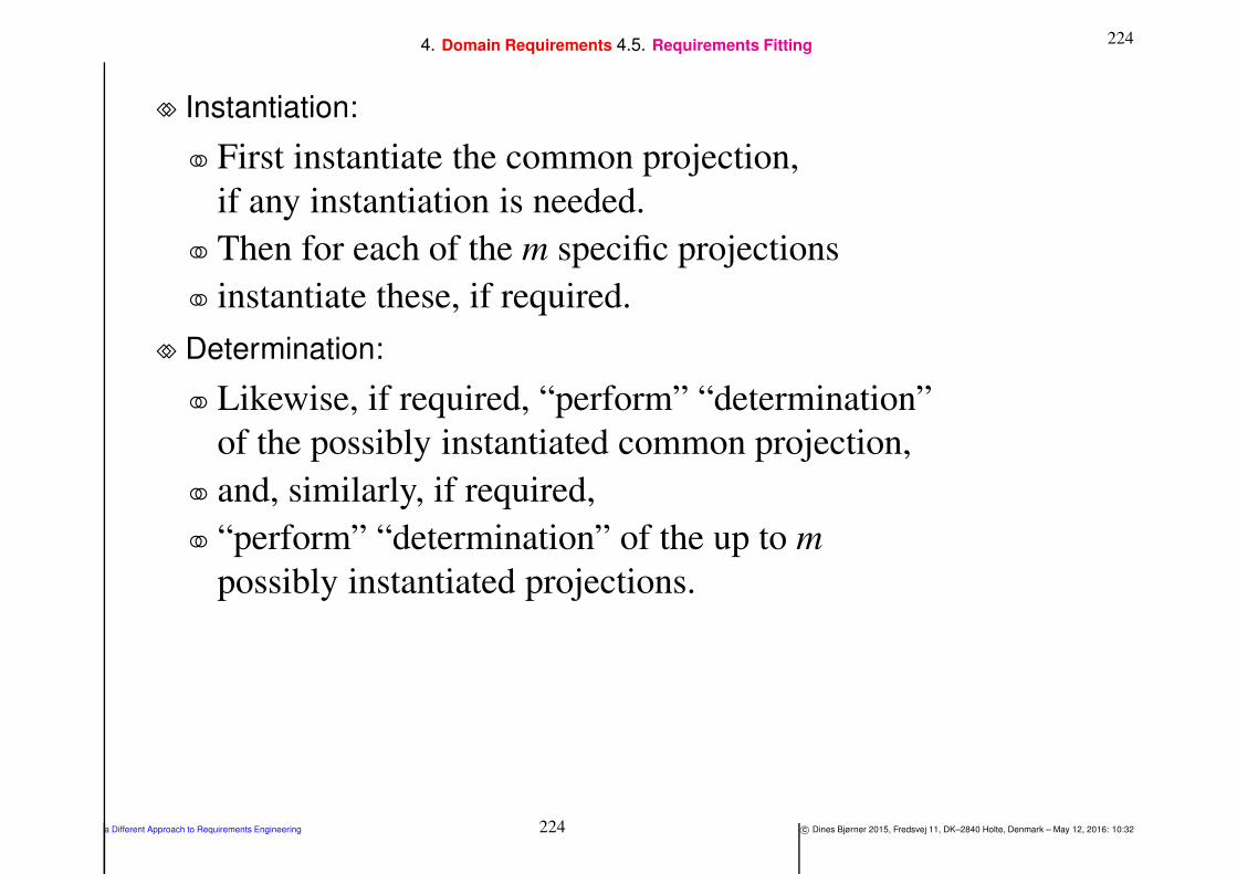
2244. Domain Requirements 4.5. Requirements Fitting
⋄⋄ Instantiation:
First instantiate the common projection,
if any instantiation is needed.
Then for each of the m specific projections
instantiate these, if required.
⋄⋄ Determination:
Likewise, if required, “perform” “determination”
of the possibly instantiated common projection,
and, similarly, if required,
“perform” “determination” of the up to m
possibly instantiated projections.
a Different Approach to Requirements Engineering 224 c© Dines Bjørner 2015, Fredsvej 11, DK–2840 Holte, Denmark – May 12, 2016: 10:32
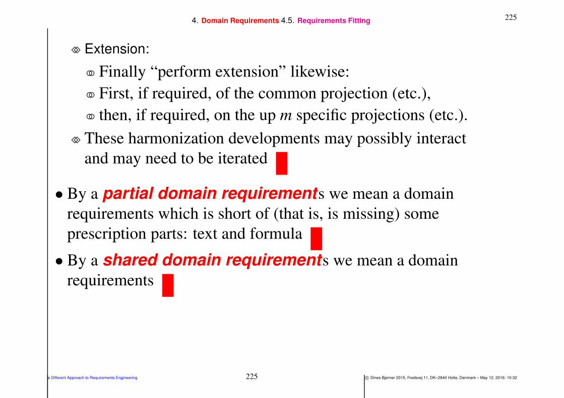
2254. Domain Requirements 4.5. Requirements Fitting
⋄⋄ Extension:
Finally “perform extension” likewise:
First, if required, of the common projection (etc.),
then, if required, on the up m specific projections (etc.).
⋄⋄ These harmonization developments may possibly interact
and may need to be iterated
• By a partial domain requirements we mean a domain
requirements which is short of (that is, is missing) some
prescription parts: text and formula
• By a shared domain requirements we mean a domain
requirements
a Different Approach to Requirements Engineering 225 c© Dines Bjørner 2015, Fredsvej 11, DK–2840 Holte, Denmark – May 12, 2016: 10:32
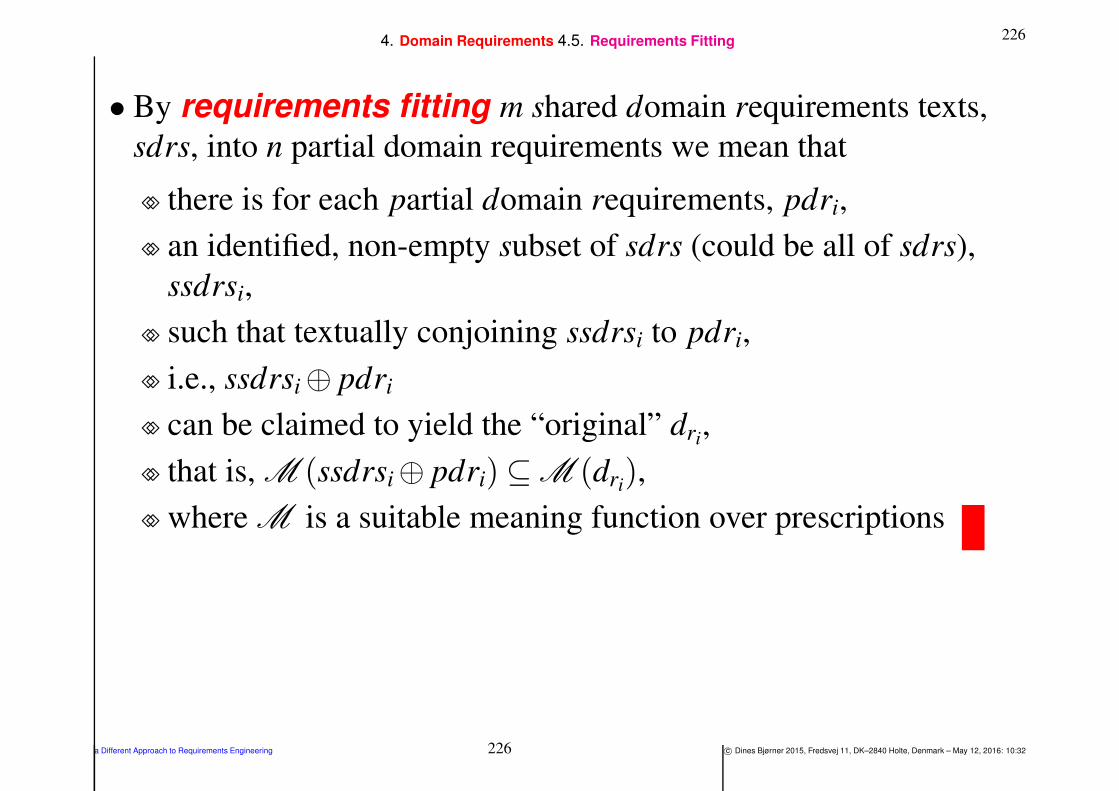
2264. Domain Requirements 4.5. Requirements Fitting
• By requirements fitting m shared domain requirements texts,
sdrs, into n partial domain requirements we mean that
⋄⋄ there is for each partial domain requirements, pdri,
⋄⋄ an identified, non-empty subset of sdrs (could be all of sdrs),
ssdrsi,
⋄⋄ such that textually conjoining ssdrsi to pdri,
⋄⋄ i.e., ssdrsi⊕ pdri
⋄⋄ can be claimed to yield the “original” dri,
⋄⋄ that is, M (ssdrsi⊕ pdri)⊆ M (dri),
⋄⋄ where M is a suitable meaning function over prescriptions
a Different Approach to Requirements Engineering 226 c© Dines Bjørner 2015, Fredsvej 11, DK–2840 Holte, Denmark – May 12, 2016: 10:32

2274. Domain Requirements 4.6. Discussion
4.6. Discussion
• Facet-oriented Fittings:
⋄⋄ An altogether different way of looking at domain requirements
may be achieved when also considering domain facets
not covered in neither the example of Sect. nor in this section
(i.e., Sect. )
nor in the following two sections.
⋄⋄ We refer to [Bjø10a].
a Different Approach to Requirements Engineering 227 c© Dines Bjørner 2015, Fredsvej 11, DK–2840 Holte, Denmark – May 12, 2016: 10:32

2284. Domain Requirements 4.6. Discussion
Example 14 Domain Requirements — Fitting:
• Example 13 hints at three possible sets of interface requirements:
⋄⋄ (i) for a road pricing [sub-]system, as will be illustrated in Sect. ;
⋄⋄ (ii) for a vehicle monitoring and control [sub-]system, and
⋄⋄ (iii) for a toll-gate monitoring and control [sub-]system.
• The vehicle monitoring and control [sub-]system would focus on
implementing the vehicle behaviour, see Items 128- 132 on
Slide 208.
• The toll-gate monitoring and control [sub-]system would focus on
implementing the calculator behaviour, see Items 134- 139 on
Slide 213.
a Different Approach to Requirements Engineering 228 c© Dines Bjørner 2015, Fredsvej 11, DK–2840 Holte, Denmark – May 12, 2016: 10:32

2294. Domain Requirements 4.6. Discussion
The fitting amounts to
• (a) making precise the (narrative and formal) texts that are specific
to each of of the three (i–iii) separate sub-system requirements are
kept separate;
• (b) ensuring that (meaning-wise) shared texts that have different
names for (meaning-wise) identical entities have these names
renamed appropriately;
• (c) that these texts are subject to commensurate and ameliorated
further requirements development;
• etcetera
a Different Approach to Requirements Engineering 229 c© Dines Bjørner 2015, Fredsvej 11, DK–2840 Holte, Denmark – May 12, 2016: 10:32
2305. Interface and Derived Requirements
5. Interface and Derived Requirements
• We remind the listener that
⋄⋄ interface requirements
can be expressed only using terms from
both the domain
and the machine
• Users are not part of the machine.
⋄⋄ So no reference can be made to users, such as
⋄⋄ “the system must be user friendly”,
⋄⋄ and the like !16
16So how do we cope with the statement: “the system must be user friendly” ? We
refer to Sect. on Slide 284 for a discussion of this issue.
a Different Approach to Requirements Engineering 230 c© Dines Bjørner 2015, Fredsvej 11, DK–2840 Holte, Denmark – May 12, 2016: 10:32

2315. Interface and Derived Requirements
• By interface requirements we [also] mean
⋄⋄ requirements prescriptions
which refines and extends the domain requirements
⋄⋄ by considering those requirementsof the domain requirements whose
endurants (parts, materials) and
perdurants (actions, events and behaviours)
⋄⋄ are “shared”
⋄⋄ between the domain and the machine(being requirements prescribed)
⋄⋄ The two interface requirements definitions above go
hand–in–hand, i.e., complement one-another.
a Different Approach to Requirements Engineering 231 c© Dines Bjørner 2015, Fredsvej 11, DK–2840 Holte, Denmark – May 12, 2016: 10:32

2325. Interface and Derived Requirements
• By derived requirements we mean
⋄⋄ requirements prescriptions
⋄⋄ which are expressed in terms of the machine concepts andfacilities
⋄⋄ introduced by the emerging requirements
a Different Approach to Requirements Engineering 232 c© Dines Bjørner 2015, Fredsvej 11, DK–2840 Holte, Denmark – May 12, 2016: 10:32
2335. Interface and Derived Requirements 5.1. Interface Requirements
5.1. Interface Requirements
5.1.1. Shared Phenomena
• By sharing we mean
⋄⋄ that some or all properties of an endurant is represented both
in the domain and
“inside” the machine, and
that their machine representation
must at suitable times
reflect their state in the domain;
and/or
⋄⋄ that an action
requires a sequence of several “on-line” interactions
between the machine (being requirements prescribed) and
the domain, usually a person or another machine;
and/or
a Different Approach to Requirements Engineering 233 c© Dines Bjørner 2015, Fredsvej 11, DK–2840 Holte, Denmark – May 12, 2016: 10:32

2345. Interface and Derived Requirements 5.1. Interface Requirements 5.1.1. Shared Phenomena
⋄⋄ that an event
arises either in the domain,
that is, in the environment of the machine,
or in the machine,
and need be communicated to the machine, respectively to the
environment;
and/or
⋄⋄ that a behaviour is manifested both
by actions and events of the domain and
by actions and events of the machine
a Different Approach to Requirements Engineering 234 c© Dines Bjørner 2015, Fredsvej 11, DK–2840 Holte, Denmark – May 12, 2016: 10:32

2355. Interface and Derived Requirements 5.1. 5.1.1.
• So a systematic reading of the domain requirements shall
⋄⋄ result in an identification of all shared
endurants,
∗ parts,
∗ materials and
∗ components;
and
perdurants
∗ actions,
∗ events and
∗ behaviours.
a Different Approach to Requirements Engineering 235 c© Dines Bjørner 2015, Fredsvej 11, DK–2840 Holte, Denmark – May 12, 2016: 10:32

2365. Interface and Derived Requirements 5.1. 5.1.1.
• Each such shared phenomenon shall then be individually dealt with:
⋄⋄ endurant sharing shall lead to interface requirements for data
initialisation and refreshment as well as for access to endurant
attributes;
⋄⋄ action sharing shall lead to interface requirements for
interactive dialogues between the machine and its environment;
⋄⋄ event sharing shall lead to interface requirements for how
such event are communicated between the environment of the
machine and the machine; and
⋄⋄ behaviour sharing shall lead to interface requirements for
action and event dialogues between the machine and its
environment.
a Different Approach to Requirements Engineering 236 c© Dines Bjørner 2015, Fredsvej 11, DK–2840 Holte, Denmark – May 12, 2016: 10:32

2375. Interface and Derived Requirements 5.1. 5.1.1. 5.1.1.1. Environment–Machine Interface:
5.1.1.1 Environment–Machine Interface:
• Domain requirements extension, Sect. 4.4,
⋄⋄ usually introduce new endurants into (i.e., ‘extend’ the) domain.
⋄⋄ Some of these endurants may become elements of
the domain requirements.
⋄⋄ Others are to be projected “away”.
⋄⋄ Those that are let into the domain requirements
either have their endurants represented, somehow,
also in the machine,
or have (some of) their properties, usually some attributes,
accessed by the machine.
a Different Approach to Requirements Engineering 237 c© Dines Bjørner 2015, Fredsvej 11, DK–2840 Holte, Denmark – May 12, 2016: 10:32

2385. Interface and Derived Requirements 5.1. 5.1.1. 5.1.1.1. Environment–Machine Interface:
⋄⋄ Similarly for perdurants.
Usually the machine representation of shared perdurants
access (some of) their properties, usually some attributes.
⋄⋄ The interface requirements must spell out
which domain extensions are shared.
⋄⋄ Thus domain extensions may necessitate a review of domain
projection,
instantiations and
determination.
a Different Approach to Requirements Engineering 238 c© Dines Bjørner 2015, Fredsvej 11, DK–2840 Holte, Denmark – May 12, 2016: 10:32

2395. Interface and Derived Requirements 5.1. 5.1.1. 5.1.1.1. Environment–Machine Interface:
• In general, there may be several of the projection–eliminated parts
(etc.) whose dynamic attributes need be accessed
in the usual way, i.e., by means of attr XYZ ch channel
communications (where XYZ is a projection–eliminated part
attribute).
a Different Approach to Requirements Engineering 239 c© Dines Bjørner 2015, Fredsvej 11, DK–2840 Holte, Denmark – May 12, 2016: 10:32
2405. Interface and Derived Requirements 5.1. 5.1.1. 5.1.1.1. Environment–Machine Interface:
Example 15 Interface Requirements — Projected
Extensions: We refer to Fig. 2 on Slide 189.
• We do not represent the GNSS system in the machine:
⋄⋄ only its “effect”: the ability to record global positions
⋄⋄ by accessing the GNSS attribute (channel):
channel
87 attr TiGPos ch[vi ]|vi:VI•vi ∈ xtr VIs(vs): TiGPos
a Different Approach to Requirements Engineering 240 c© Dines Bjørner 2015, Fredsvej 11, DK–2840 Holte, Denmark – May 12, 2016: 10:32

2415. Interface and Derived Requirements 5.1. 5.1.1. 5.1.1.1. Environment–Machine Interface:
• And we do not really represent the gate nor its sensors and actuator
in the machine.
• But we do give an idealised description of the gate behaviour,
see Items 134–139
• Instead we represent their dynamic gate attributes:
(97) the vehicle entry sensors (leftmost s),
(97) the vehicle identity sensor (center ), and
(98) the vehicle exit sensors (rightmost s)
• by channels — we refer to Example 13 (Sect. , Slide 192):
channel
97 attr entry ch[gi ]|gi:GI•xtr eGIds(trn)′′
enter′′
97 attr exit ch[gi ]|gi:GI•xtr xGIds(trn)′′
exit′′
98 attr identity ch[gi ]|gi:GI•xtr GIds(trn) TIVI
a Different Approach to Requirements Engineering 241 c© Dines Bjørner 2015, Fredsvej 11, DK–2840 Holte, Denmark – May 12, 2016: 10:32
2425. Interface and Derived Requirements 5.1. 5.1.2. Shared Endurants
5.1.2. Shared Endurants
Example 16 Interface Requirements. Shared Endurants:
• The main shared endurants are
⋄⋄ the vehicles,
⋄⋄ the net (hubs, links, toll-gates) and
⋄⋄ the price calculator.
• As domain endurants hubs and links undergo changes,
⋄⋄ all the time,
⋄⋄ with respect to the values of several attributes:
length, geodetic information, names,
wear and tear (where-ever applicable),
last/next scheduled maintenance (where-ever applicable),
state and state space,
and many others.
a Different Approach to Requirements Engineering 242 c© Dines Bjørner 2015, Fredsvej 11, DK–2840 Holte, Denmark – May 12, 2016: 10:32

2435. Interface and Derived Requirements 5.1. 5.1.2. Shared Endurants
• Similarly for vehicles:
⋄⋄ their position,
⋄⋄ velocity and acceleration, and
⋄⋄ many other attributes.
• We then come up with something like
⋄⋄ hubs and links are to be represented as tuples of relations;
⋄⋄ each net will be represented by a pair of relations
a hubs relation and a links relation;
each hub and each link may or will be represented by several
tuples;
⋄⋄ etcetera.
• In this database modeling effort it must be secured that “standard”
operations on nets, hubs and links can be supported by the chosen
relational database system
a Different Approach to Requirements Engineering 243 c© Dines Bjørner 2015, Fredsvej 11, DK–2840 Holte, Denmark – May 12, 2016: 10:32

2445. Interface and Derived Requirements 5.1. 5.1.2. Shared Endurants 5.1.2.1. Data Initialisation:
5.1.2.1 Data Initialisation:
• In general, one must prescribe data initialisation, that is provision
for
⋄⋄ an interactive user interface dialogue with a set of proper display
screens,
one for establishing net, hub or link attributes names and their
types, and, for example,
two for the input of hub and link attribute values.
⋄⋄ Interaction prompts may be prescribed:
next input,
on-line vetting and
display of evolving net, etc.
⋄⋄ These and many other aspects may therefore need prescriptions.
a Different Approach to Requirements Engineering 244 c© Dines Bjørner 2015, Fredsvej 11, DK–2840 Holte, Denmark – May 12, 2016: 10:32
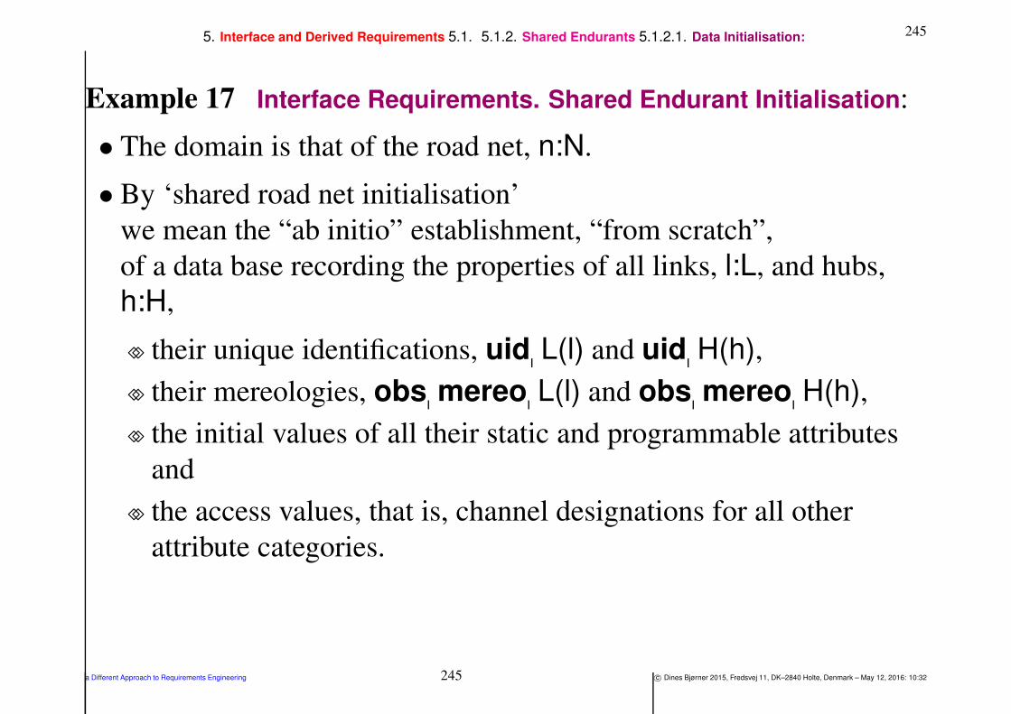
2455. Interface and Derived Requirements 5.1. 5.1.2. Shared Endurants 5.1.2.1. Data Initialisation:
Example 17 Interface Requirements. Shared Endurant Initialisation:
• The domain is that of the road net, n:N.
• By ‘shared road net initialisation’
we mean the “ab initio” establishment, “from scratch”,
of a data base recording the properties of all links, l:L, and hubs,
h:H,
⋄⋄ their unique identifications, uid L(l) and uid H(h),
⋄⋄ their mereologies, obs mereo L(l) and obs mereo H(h),
⋄⋄ the initial values of all their static and programmable attributes
and
⋄⋄ the access values, that is, channel designations for all other
attribute categories.
a Different Approach to Requirements Engineering 245 c© Dines Bjørner 2015, Fredsvej 11, DK–2840 Holte, Denmark – May 12, 2016: 10:32

2465. Interface and Derived Requirements 5.1. 5.1.2. Shared Endurants 5.1.2.1. Data Initialisation:
140 There are rl and rh “recorders” recording link, respectively hub
properties – with each recorder having a unique identity.
141 Each recorder is charged with the recording of a set of links or a set
of hubs according to some partitioning of all such.
142 The recorders inform a central data base, net db, of their
recordings (ri,hol,(u j,m j,attrs j)) where
143 ri is the identity of the recorder,
144 hol is either a hub or a link literal,
145 u j = uid L(l) or uid H(h) for some link or hub,
146 m j = obs mereo L(l) or obs mereo H(h) for that link or hub
and
147 attrs j are attributes for that link or hub — where attributes is a
function which “records” all respective static and dynamic
attributes (left undefined).
a Different Approach to Requirements Engineering 246 c© Dines Bjørner 2015, Fredsvej 11, DK–2840 Holte, Denmark – May 12, 2016: 10:32
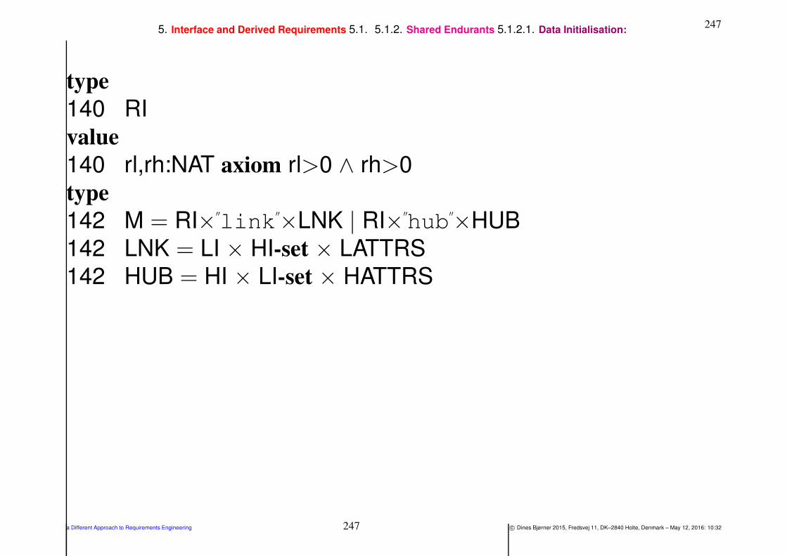
2475. Interface and Derived Requirements 5.1. 5.1.2. Shared Endurants 5.1.2.1. Data Initialisation:
type
140 RI
value
140 rl,rh:NAT axiom rl>0 ∧ rh>0
type
142 M = RI×′′
link′′
×LNK | RI×′′
hub′′
×HUB
142 LNK = LI × HI-set × LATTRS
142 HUB = HI × LI-set × HATTRS
a Different Approach to Requirements Engineering 247 c© Dines Bjørner 2015, Fredsvej 11, DK–2840 Holte, Denmark – May 12, 2016: 10:32
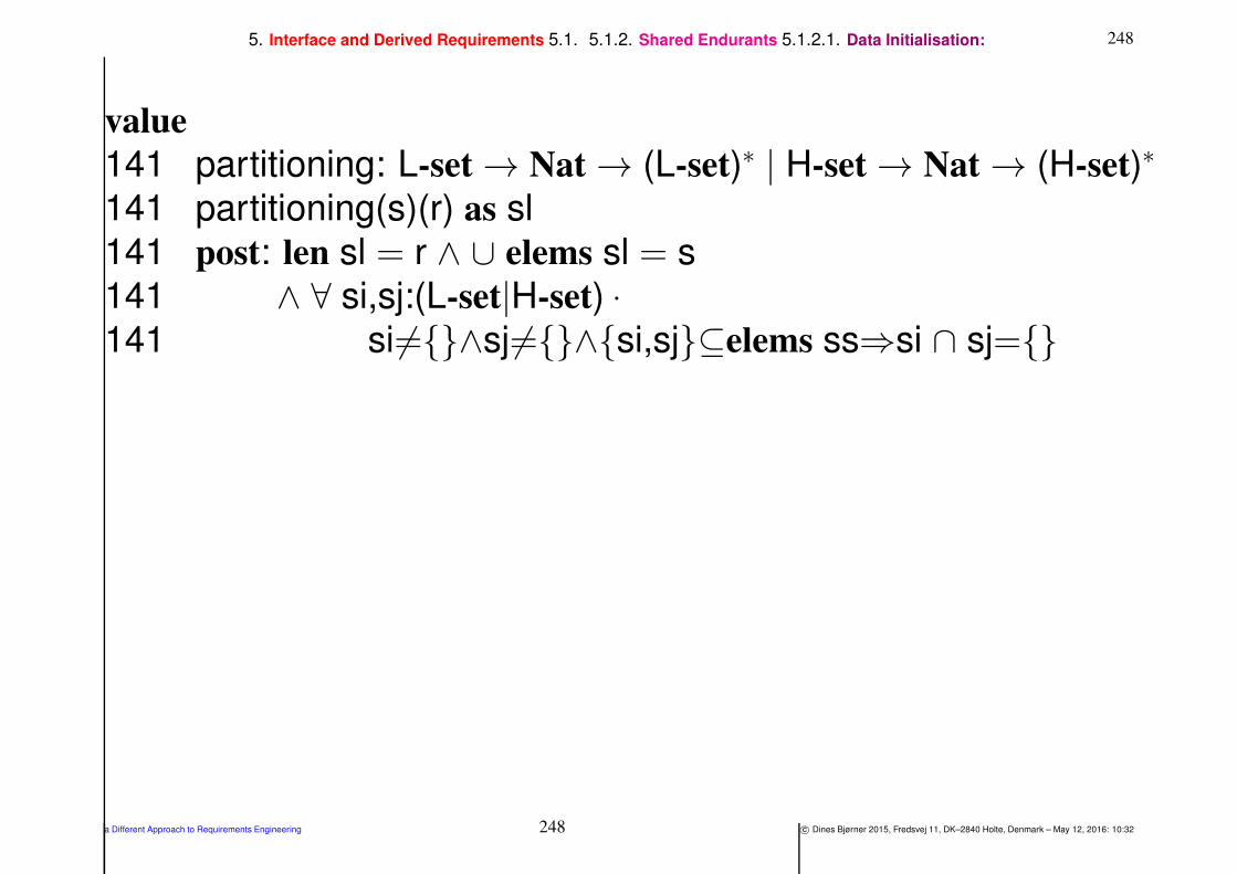
2485. Interface and Derived Requirements 5.1. 5.1.2. Shared Endurants 5.1.2.1. Data Initialisation:
value
141 partitioning: L-set → Nat → (L-set)∗ | H-set → Nat → (H-set)∗
141 partitioning(s)(r) as sl
141 post: len sl = r ∧ ∪ elems sl = s
141 ∧ ∀ si,sj:(L-set|H-set) •
141 si 6=∧sj 6=∧si,sj⊆elems ss⇒si ∩ sj=
a Different Approach to Requirements Engineering 248 c© Dines Bjørner 2015, Fredsvej 11, DK–2840 Holte, Denmark – May 12, 2016: 10:32

2495. Interface and Derived Requirements 5.1. 5.1.2. Shared Endurants 5.1.2.1. Data Initialisation:
148 The rl + rh recorder behaviours interact with the one net db
behaviour
channel
148 r db: RI×(LNK|HUB)
value
148 link rec: RI → L-set → out r db Unit
148 hub rec: RI → H-set → out r db Unit
148 net db: Unit → in r db Unit
a Different Approach to Requirements Engineering 249 c© Dines Bjørner 2015, Fredsvej 11, DK–2840 Holte, Denmark – May 12, 2016: 10:32

2505. Interface and Derived Requirements 5.1. 5.1.2. Shared Endurants 5.1.2.1. Data Initialisation:
149 The data base behaviour, net db, offers to receive messages from
the link and hub recorders.
150 The data base behaviour, net db, deposits these messages in
respective variables.
151 Initially there is a net, n : N,
152 from which is observed its links and hubs.
153 These sets are partitioned into rl, respectively rh length lists of
non-empty links and hubs.
154 The ab-initio data initialisation behaviour, ab initio data, is then
the parallel composition of link recorder, hub recorder and data
base behaviours with link and hub recorder being allotted
appropriate link, respectively hub sets.
155 We construct, for technical reasons, as the listener will soon see,
disjoint lists of link, respectively hub recorder identities.
a Different Approach to Requirements Engineering 250 c© Dines Bjørner 2015, Fredsvej 11, DK–2840 Holte, Denmark – May 12, 2016: 10:32

2515. Interface and Derived Requirements 5.1. 5.1.2. Shared Endurants 5.1.2.1. Data Initialisation:
value
149 net db:
variable
150 lnk db: (RI×LNK)-set
150 hub db: (RI×HUB)-set
value
151 n:N
152 ls:L-set = obs Ls(obs LS(n))
152 hs:H-set = obs Hs(obs HS(n))
153 lsl:(L-set)∗ = partitioning(ls)(rl)
153 lhl:(H-set)∗ = partitioning(hs)(rh)
155 rill:RI∗ axiom len rill = rl = card elems rill
155 rihl:RI∗ axiom len rihl = rh = card elems rihl
154 ab initio data: Unit → Unit
154 ab initio data() ≡154 ‖ lnk rec(rill[ i ])(lsl[ i ])|i:Nat•1≤i≤rl ‖154 ‖ hub rec(rihl[ i ])(lhl[ i ])|i:Nat•1≤i≤rh154 ‖ net db()
a Different Approach to Requirements Engineering 251 c© Dines Bjørner 2015, Fredsvej 11, DK–2840 Holte, Denmark – May 12, 2016: 10:32

2525. Interface and Derived Requirements 5.1. 5.1.2. Shared Endurants 5.1.2.1. Data Initialisation:
156 The link and the hub recorders are near-identical behaviours.
157 They both revolve around an imperatively stated for all ... do ...
end.
The selected link (or hub) is inspected and the “data” for the data
base is prepared from
158 the unique identifier,
159 the mereology, and
160 the attributes.
161 These “data” are sent, as a message, prefixed the senders identity,
to the data base behaviour.
162 We presently leave the . . . unexplained.
a Different Approach to Requirements Engineering 252 c© Dines Bjørner 2015, Fredsvej 11, DK–2840 Holte, Denmark – May 12, 2016: 10:32

2535. Interface and Derived Requirements 5.1. 5.1.2. Shared Endurants 5.1.2.1. Data Initialisation:
value
148 link rec: RI → L-set → Unit
156 link rec(ri,ls) ≡157 for ∀ l:L•l ∈ ls do uid L(l)
158 let lnk = (uid L(l),
159 obs mereo L(l),
160 attributes(l)) in
161 rdb ! (ri,′′
link′′
,lnk);
162 ... end
157 end
a Different Approach to Requirements Engineering 253 c© Dines Bjørner 2015, Fredsvej 11, DK–2840 Holte, Denmark – May 12, 2016: 10:32

2545. Interface and Derived Requirements 5.1. 5.1.2. Shared Endurants 5.1.2.1. Data Initialisation:
148 hub rec: RI × H-set → Unit
156 hub rec(ri,hs) ≡157 for ∀ h:H•h ∈ hs do uid H(h)
158 let hub = (uid L(h),
159 obs mereo H(h),
160 attributes(h)) in
161 rdb ! (ri,′′
hub′′
,hub);
162 ... end
157 end
a Different Approach to Requirements Engineering 254 c© Dines Bjørner 2015, Fredsvej 11, DK–2840 Holte, Denmark – May 12, 2016: 10:32
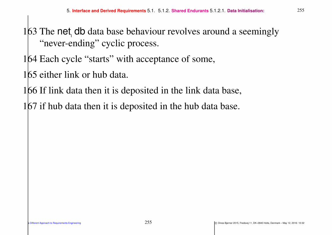
2555. Interface and Derived Requirements 5.1. 5.1.2. Shared Endurants 5.1.2.1. Data Initialisation:
163 The net db data base behaviour revolves around a seemingly
“never-ending” cyclic process.
164 Each cycle “starts” with acceptance of some,
165 either link or hub data.
166 If link data then it is deposited in the link data base,
167 if hub data then it is deposited in the hub data base.
a Different Approach to Requirements Engineering 255 c© Dines Bjørner 2015, Fredsvej 11, DK–2840 Holte, Denmark – May 12, 2016: 10:32
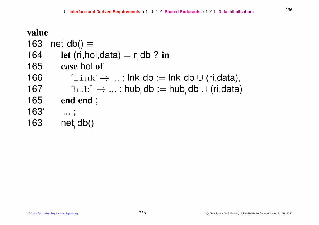
2565. Interface and Derived Requirements 5.1. 5.1.2. Shared Endurants 5.1.2.1. Data Initialisation:
value
163 net db() ≡164 let (ri,hol,data) = r db ? in
165 case hol of
166′′
link′′
→ ... ; lnk db := lnk db ∪ (ri,data),
167′′
hub′′
→ ... ; hub db := hub db ∪ (ri,data)
165 end end ;
163′ ... ;
163 net db()
a Different Approach to Requirements Engineering 256 c© Dines Bjørner 2015, Fredsvej 11, DK–2840 Holte, Denmark – May 12, 2016: 10:32
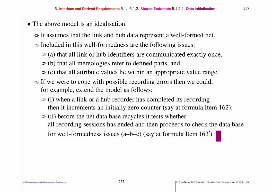
2575. Interface and Derived Requirements 5.1. 5.1.2. Shared Endurants 5.1.2.1. Data Initialisation:
• The above model is an idealisation.
⋄⋄ It assumes that the link and hub data represent a well-formed net.
⋄⋄ Included in this well-formedness are the following issues:
(a) that all link or hub identifiers are communicated exactly once,
(b) that all mereologies refer to defined parts, and
(c) that all attribute values lie within an appropriate value range.
⋄⋄ If we were to cope with possible recording errors then we could,
for example, extend the model as follows:
(i) when a link or a hub recorder has completed its recording
then it increments an initially zero counter (say at formula Item 162);
(ii) before the net data base recycles it tests whether
all recording sessions has ended and then proceeds to check the data base
for well-formedness issues (a–b–c) (say at formula Item 163′)
a Different Approach to Requirements Engineering 257 c© Dines Bjørner 2015, Fredsvej 11, DK–2840 Holte, Denmark – May 12, 2016: 10:32

2585. Interface and Derived Requirements 5.1. 5.1.2. Shared Endurants 5.1.2.1. Data Initialisation:
• The above example illustrates the ‘interface’ phenomenon:
⋄⋄ In the formulas, for example, we show both
manifest domain entities, viz., n, l,h etc., and
abstract (required) software objects, viz., (ui,me,attrs).
a Different Approach to Requirements Engineering 258 c© Dines Bjørner 2015, Fredsvej 11, DK–2840 Holte, Denmark – May 12, 2016: 10:32

2595. Interface and Derived Requirements 5.1. 5.1.2. Shared Endurants 5.1.2.2. Data Refreshment:
5.1.2.2 Data Refreshment:
• One must also prescribe data refreshment:
⋄⋄ an interactive user interface dialogue
with a set of proper display screens
one for selecting the updating of net, of hub or of link attribute
names and their types and, for example,
two for the respective update of hub and link attribute values.
⋄⋄ Interaction-prompts may be prescribed:
next update,
on-line vetting and
display of revised net, etc.
⋄⋄ These and many other aspects may therefore need prescriptions.
a Different Approach to Requirements Engineering 259 c© Dines Bjørner 2015, Fredsvej 11, DK–2840 Holte, Denmark – May 12, 2016: 10:32

2605. Interface and Derived Requirements 5.1. 5.1.3. Shared Perdurants
5.1.3. Shared Perdurants
• We can expect that
⋄⋄ for every part in the domain
⋄⋄ that is shared with the machine and
⋄⋄ for which there is a corresponding behaviour of the domain
⋄⋄ there might be a corresponding process of the machine.
• If a projected, instantiated, ‘determinated’ and possibly extended
domain part is dynamic,
then it is definitely a candidate for being shared
and having an associated machine process.
a Different Approach to Requirements Engineering 260 c© Dines Bjørner 2015, Fredsvej 11, DK–2840 Holte, Denmark – May 12, 2016: 10:32
2615. Interface and Derived Requirements 5.1. 5.1.3. Shared Perdurants
• We now illustrate the concept of shared perdurants
⋄⋄ via the domain requirements extension example
⋄⋄ of Sect. 4.4, i.e. Example 13 Slides 181–217.
a Different Approach to Requirements Engineering 261 c© Dines Bjørner 2015, Fredsvej 11, DK–2840 Holte, Denmark – May 12, 2016: 10:32
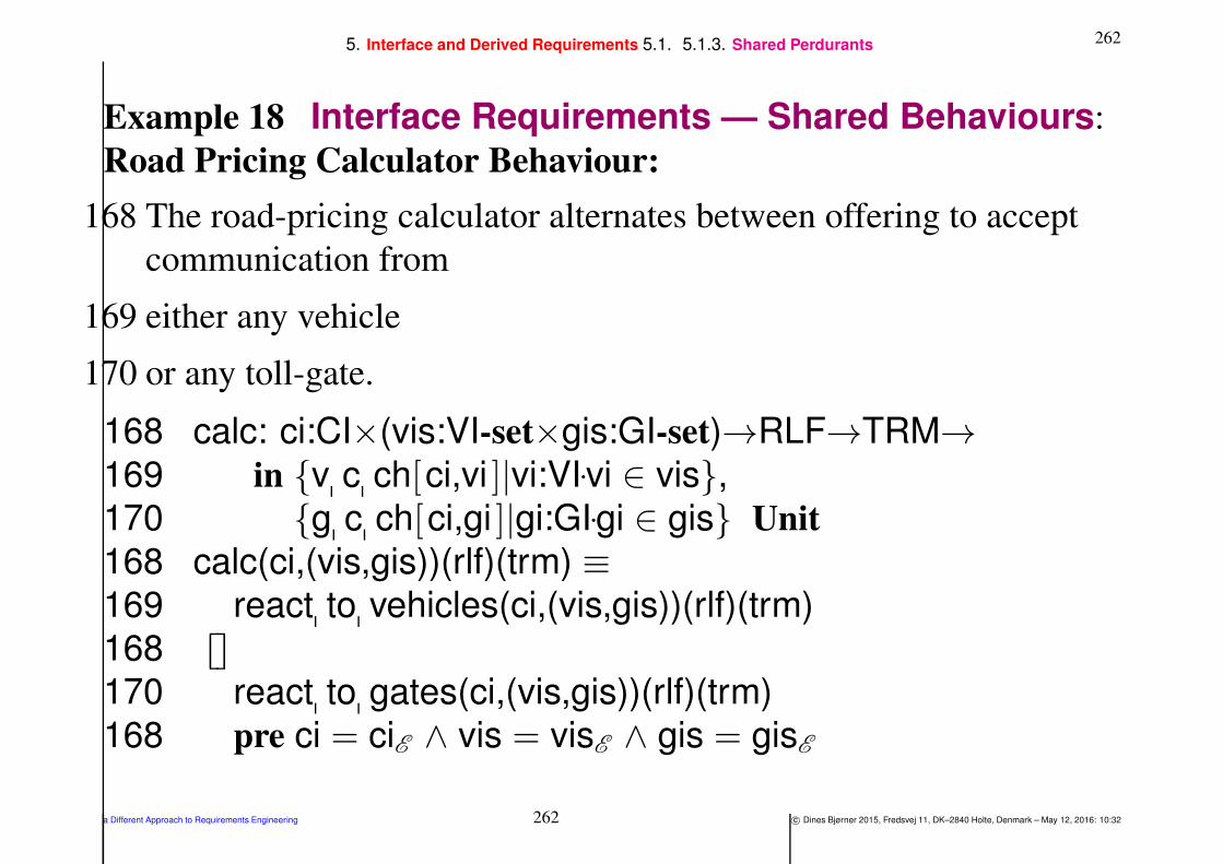
2625. Interface and Derived Requirements 5.1. 5.1.3. Shared Perdurants
Example 18 Interface Requirements — Shared Behaviours:
Road Pricing Calculator Behaviour:
168 The road-pricing calculator alternates between offering to accept
communication from
169 either any vehicle
170 or any toll-gate.
168 calc: ci:CI×(vis:VI-set×gis:GI-set)→RLF→TRM→169 in v c ch[ci,vi ]|vi:VI•vi ∈ vis,
170 g c ch[ci,gi ]|gi:GI•gi ∈ gis Unit
168 calc(ci,(vis,gis))(rlf)(trm) ≡169 react to vehicles(ci,(vis,gis))(rlf)(trm)
168 ⌈⌉⌊⌋170 react to gates(ci,(vis,gis))(rlf)(trm)
168 pre ci = ciE ∧ vis = visE ∧ gis = gisE
a Different Approach to Requirements Engineering 262 c© Dines Bjørner 2015, Fredsvej 11, DK–2840 Holte, Denmark – May 12, 2016: 10:32

2635. Interface and Derived Requirements 5.1. 5.1.3. Shared Perdurants
171 If the communication is from a vehicle inside the toll-road net
172 then its toll-road net position, vp, is found from the road location
function, rlf,
173 and the calculator resumes its work with the traffic map, trm,
suitably updated,
174 otherwise the calculator resumes its work with no changes.
169 react to vehicles(ci,(vis,gis),vplf)(trm) ≡169 let (vi,(τ ,lpos)) = ⌈⌉⌊⌋v c ch[ci,vi ]?|vi:VI•vi∈ vis in
171 if vi ∈ dom trm
172 then let vp = vplf(lpos) in
173 calc(ci,(vis,gis),vplf)(trm†[vi 7→trm〈(τ ,vp)〉 ]) end
174 else calc(ci,(vis,gis),vplf)(trm) end end
a Different Approach to Requirements Engineering 263 c© Dines Bjørner 2015, Fredsvej 11, DK–2840 Holte, Denmark – May 12, 2016: 10:32

2645. Interface and Derived Requirements 5.1. 5.1.3. Shared Perdurants
175 If the communication is from a gate,
176 then that gate is either an entry gate or an exit gate;
177 if it is an entry gate
178 then the calculator resumes its work with the vehicle (that passed
the entry gate) now recorded, afresh, in the traffic map, trm.
179 Else it is an exit gate and
180 the calculator concludes that the vehicle has ended its
to-be-paid-for journey inside the toll-road net, and hence to be
billed;
181 then the calculator resumes its work with the vehicle now removed
from the traffic map, trm.
a Different Approach to Requirements Engineering 264 c© Dines Bjørner 2015, Fredsvej 11, DK–2840 Holte, Denmark – May 12, 2016: 10:32
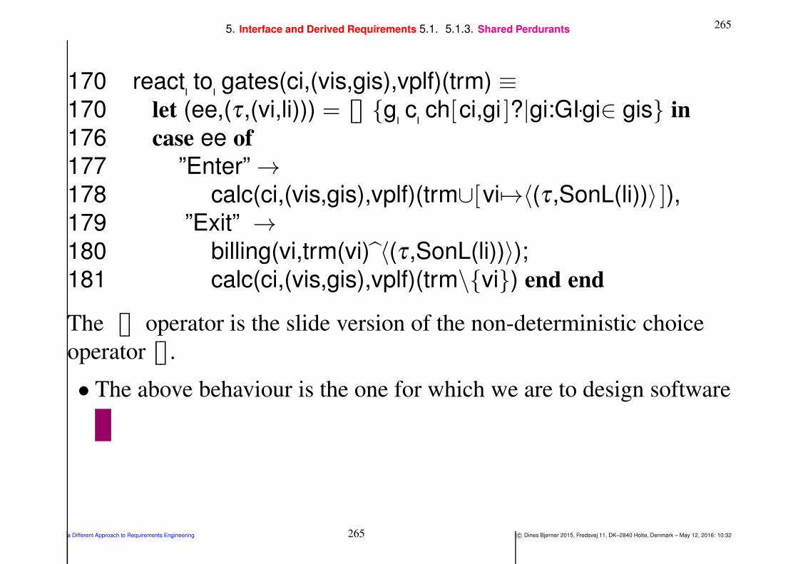
2655. Interface and Derived Requirements 5.1. 5.1.3. Shared Perdurants
170 react to gates(ci,(vis,gis),vplf)(trm) ≡170 let (ee,(τ ,(vi,li))) = ⌈⌉⌊⌋ g c ch[ci,gi ]?|gi:GI•gi∈ gis in
176 case ee of
177 ”Enter” →178 calc(ci,(vis,gis),vplf)(trm∪[vi 7→〈(τ ,SonL(li))〉 ]),179 ”Exit” →180 billing(vi,trm(vi) 〈(τ ,SonL(li))〉);181 calc(ci,(vis,gis),vplf)(trm\vi) end end
The ⌈⌉⌊⌋ operator is the slide version of the non-deterministic choice
operator ⌈⌉⌊⌋.
• The above behaviour is the one for which we are to design software
a Different Approach to Requirements Engineering 265 c© Dines Bjørner 2015, Fredsvej 11, DK–2840 Holte, Denmark – May 12, 2016: 10:32
2665. Interface and Derived Requirements 5.2. Derived Requirements
5.2. Derived Requirements
Definition 18 Derived Perdurant: By a derived perdurant we
shall understand
• a perdurant which is not shared with the domain,
• but which focus on exploiting facilities
• of the software or hardware of the machine
a Different Approach to Requirements Engineering 266 c© Dines Bjørner 2015, Fredsvej 11, DK–2840 Holte, Denmark – May 12, 2016: 10:32
2675. Interface and Derived Requirements 5.2. Derived Requirements
• “Exploiting facilities of the software”, to us,
⋄⋄ means that requirements,
⋄⋄ imply the presence, in the machine, of concepts (i.e., hardware
and/or software),
⋄⋄ and that it is these concepts
⋄⋄ that the derived requirements “rely” on.
• We illustrate all three forms of perdurant extensions:
⋄⋄ derived actions,
⋄⋄ derived events and
⋄⋄ derived behaviours.
a Different Approach to Requirements Engineering 267 c© Dines Bjørner 2015, Fredsvej 11, DK–2840 Holte, Denmark – May 12, 2016: 10:32
2685. Interface and Derived Requirements 5.2. Derived Requirements 5.2.1. Derived Actions
5.2.1. Derived Actions
Definition 19 Derived Action:
• By a derived action we shall understand
⋄⋄ (a) a conceptual action
⋄⋄ (b) that calculates
a usually non-Boolean valued property from,
and possibly changes to
⋄⋄ (c) a machine behaviour state
⋄⋄ (d) as instigated by some actor
a Different Approach to Requirements Engineering 268 c© Dines Bjørner 2015, Fredsvej 11, DK–2840 Holte, Denmark – May 12, 2016: 10:32

2695. Interface and Derived Requirements 5.2. Derived Requirements 5.2.1. Derived Actions
Example 19 Domain Requirements. Derived Action: Tracing
Vehicles:
• The example is based on the Road Pricing Calculator Behaviour of
Example 18 on Slide 262.
⋄⋄ The “external” actor, i.e., a user of the Road Pricing Calculator
system
⋄⋄ wishes to trace specific vehicles “cruising” the toll-road.
⋄⋄ That user (a Road Pricing Calculator staff),
issues a command to the Road Pricing Calculator system,
with the identity of a vehicle
not already being traced.
⋄⋄ As a result the Road Pricing Calculator system
augments a possibly void trace of
the timed toll-road positions of vehicles.
a Different Approach to Requirements Engineering 269 c© Dines Bjørner 2015, Fredsvej 11, DK–2840 Holte, Denmark – May 12, 2016: 10:32

2705. Interface and Derived Requirements 5.2. Derived Requirements 5.2.1. Derived Actions
• We augment the definition of the calculator definition
Items 168–181, Slides 262–265.
182 Traces are modeled by a pair of dynamic attributes:
a. as a programmable attribute, tra:TRA, of the set of identifiers of
vehicles being traced, and
b. as a reactive attribute, vdu:VDU 17, that maps vehicle identifiers
into time-stamped sequences of simple vehicle positions, i.e., as
a subset of the trm:TRM programmable attribute.
183 The actor-to-calculator begin or end trace command, cmd:Cmd, is
modeled as an autonomous dynamic attribute of the calculator.
184 The calculator signature is furthermore augmented with the three
attributes mentioned above.
17VDU: visual display unit
a Different Approach to Requirements Engineering 270 c© Dines Bjørner 2015, Fredsvej 11, DK–2840 Holte, Denmark – May 12, 2016: 10:32

2715. Interface and Derived Requirements 5.2. Derived Requirements 5.2.1. Derived Actions
185 The occurrence and handling of an actor trace command is modeled
as a non-deterministic external choice and a react to trace cmdbehaviour.
186 The reactive attribute value (attr vdu ch?) is that subset of the
traffic map (trm) which records just the time-stamped sequences of
simple vehicle positions being traced (tra).
type
182a. TRA = VI-set
182b. VDU = TRM
183 Cmd = BTr | ETr
183 BTr :: VI
183 ETr :: VI
a Different Approach to Requirements Engineering 271 c© Dines Bjørner 2015, Fredsvej 11, DK–2840 Holte, Denmark – May 12, 2016: 10:32

2725. Interface and Derived Requirements 5.2. Derived Requirements 5.2.1. Derived Actions
value
184 calc: ci:CI×(vis:VI-set×gis:GI-set) → RLF → TRM → TRA
169,170 in v c ch[ci,vi ]|vi:VI•vi ∈ vis,
169,170 g c ch[ci,gi ]|gi:GI•gi ∈ gis,
185,186 attr cmd ch,attr vdu ch Unit
168 calc(ci,(vis,gis))(rlf)(trm)(tra) ≡169 react to vehicles(ci,(vis,gis),)(rlf)(trm)(tra)
170 ⌈⌉⌊⌋ react to gates(ci,(vis,gis))(rlf)(trm)(tra)
185 ⌈⌉⌊⌋ react to trace cmd(ci,(vis,gis))(rlf)(trm)(tra)
168 pre ci = ciE ∧ vis = visE ∧ gis = gisE
186 axiom attr vdu ch[ci ]? = trm|tra
a Different Approach to Requirements Engineering 272 c© Dines Bjørner 2015, Fredsvej 11, DK–2840 Holte, Denmark – May 12, 2016: 10:32

2735. Interface and Derived Requirements 5.2. Derived Requirements 5.2.1. Derived Actions
187 The react to trace cmd alternative behaviour is either a ”Begin” or
an ”End” request which identifies the affected vehicle.
188 If it is a ”Begin” request
189 and the identified vehicle is already being traced then we do not
prescribe what to do !
190 Else we resume the calculator behaviour, now recording that
vehicle as being traced.
191 If it is an ”End” request
192 and the identified vehicle is already being traced then we do not
prescribe what to do !
193 Else we resume the calculator behaviour, now recording that
vehicle as no longer being traced.
a Different Approach to Requirements Engineering 273 c© Dines Bjørner 2015, Fredsvej 11, DK–2840 Holte, Denmark – May 12, 2016: 10:32
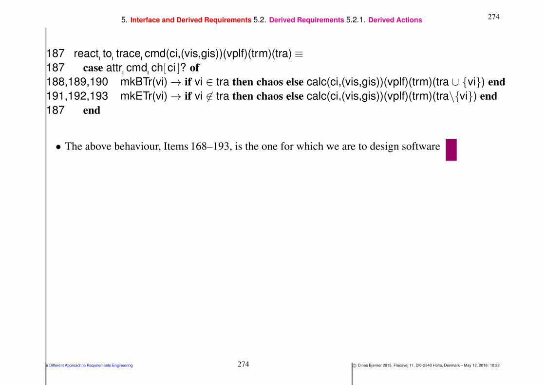
2745. Interface and Derived Requirements 5.2. Derived Requirements 5.2.1. Derived Actions
187 react to trace cmd(ci,(vis,gis))(vplf)(trm)(tra) ≡
187 case attr cmd ch[ci ]? of
188,189,190 mkBTr(vi) → if vi ∈ tra then chaos else calc(ci,(vis,gis))(vplf)(trm)(tra ∪ vi) end
191,192,193 mkETr(vi) → if vi 6∈ tra then chaos else calc(ci,(vis,gis))(vplf)(trm)(tra\vi) end
187 end
• The above behaviour, Items 168–193, is the one for which we are to design software
a Different Approach to Requirements Engineering 274 c© Dines Bjørner 2015, Fredsvej 11, DK–2840 Holte, Denmark – May 12, 2016: 10:32
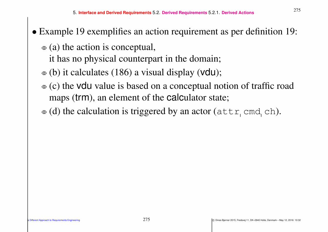
2755. Interface and Derived Requirements 5.2. Derived Requirements 5.2.1. Derived Actions
• Example 19 exemplifies an action requirement as per definition 19:
⋄⋄ (a) the action is conceptual,
it has no physical counterpart in the domain;
⋄⋄ (b) it calculates (186) a visual display (vdu);
⋄⋄ (c) the vdu value is based on a conceptual notion of traffic road
maps (trm), an element of the calculator state;
⋄⋄ (d) the calculation is triggered by an actor (attr cmd ch).
a Different Approach to Requirements Engineering 275 c© Dines Bjørner 2015, Fredsvej 11, DK–2840 Holte, Denmark – May 12, 2016: 10:32

2765. Interface and Derived Requirements 5.2. Derived Requirements 5.2.2. Derived Events
5.2.2. Derived Events
Definition 20 Derived Event: By a derived event we shall
understand
• (a) a conceptual event,
• (b) that calculates a property or some non-Boolean value
• (c) from a machine behaviour state change
a Different Approach to Requirements Engineering 276 c© Dines Bjørner 2015, Fredsvej 11, DK–2840 Holte, Denmark – May 12, 2016: 10:32

2775. Interface and Derived Requirements 5.2. Derived Requirements 5.2.2. Derived Events
Example 20 Domain Requirements. Derived Event: Current
Maximum Flow:
• The example is based on the Road Pricing Calculator Behaviour of
Examples 19 and 18 on Slide 262.
⋄⋄ By “the current maximum flow” we understand
a time-stamped natural number, the number
representing the highest number of vehicles which
∗ at the time-stamped moment cruised
∗ or now cruises
around the toll-road net.
• We augment the definition of the calculator definition
Items 168–193, Slides 262–274.
a Different Approach to Requirements Engineering 277 c© Dines Bjørner 2015, Fredsvej 11, DK–2840 Holte, Denmark – May 12, 2016: 10:32

2785. Interface and Derived Requirements 5.2. Derived Requirements 5.2.2. Derived Events
194 We augment calculator signature with
195 a time-stamped natural number valued dynamic programmable
attribute, (t:T,max:Max).
196 Whenever a vehicle enters the toll-road net, through one of its
[entry] gates,
a. it is checked whether the resulting number of vehicles recorded
in the road traffic map is higher than the hitherto maximum
recorded number.
b. If so, that programmable attribute has its number element
“upped” by one.
c. Otherwise not.
197 No changes are to be made to the react to gates behaviour
(Items 170–181 Slide 265) when a vehicle exits the toll-road net.
a Different Approach to Requirements Engineering 278 c© Dines Bjørner 2015, Fredsvej 11, DK–2840 Holte, Denmark – May 12, 2016: 10:32
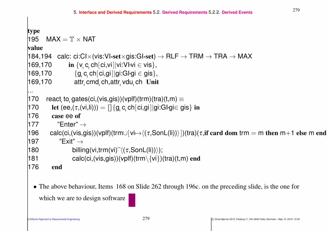
2795. Interface and Derived Requirements 5.2. Derived Requirements 5.2.2. Derived Events
type
195 MAX = T × NAT
value
184,194 calc: ci:CI×(vis:VI-set×gis:GI-set) → RLF → TRM → TRA → MAX
169,170 in v c ch[ci,vi ]|vi:VI•vi ∈ vis,
169,170 g c ch[ci,gi ]|gi:GI•gi ∈ gis,
169,170 attr cmd ch,attr vdu ch Unit
...
170 react to gates(ci,(vis,gis))(vplf)(trm)(tra)(t,m) ≡
170 let (ee,(τ ,(vi,li))) = ⌈⌉⌊⌋g c ch[ci,gi ]|gi:GI•gi∈ gis in
176 case ee of
177 ”Enter” →
196 calc(ci,(vis,gis))(vplf)(trm∪[vi 7→〈(τ ,SonL(li))〉 ])(tra)(τ ,if card dom trm = m then m+1 else m end),
197 ”Exit” →
180 billing(vi,trm(vi) 〈(τ ,SonL(li))〉);
181 calc(ci,(vis,gis))(vplf)(trm\vi)(tra)(t,m) end
176 end
• The above behaviour, Items 168 on Slide 262 through 196c. on the preceding slide, is the one for
which we are to design software
a Different Approach to Requirements Engineering 279 c© Dines Bjørner 2015, Fredsvej 11, DK–2840 Holte, Denmark – May 12, 2016: 10:32
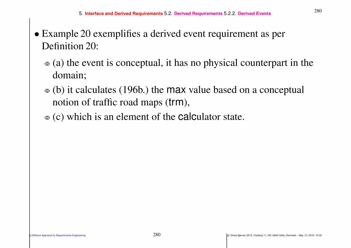
2805. Interface and Derived Requirements 5.2. Derived Requirements 5.2.2. Derived Events
• Example 20 exemplifies a derived event requirement as per
Definition 20:
⋄⋄ (a) the event is conceptual, it has no physical counterpart in the
domain;
⋄⋄ (b) it calculates (196b.) the max value based on a conceptual
notion of traffic road maps (trm),
⋄⋄ (c) which is an element of the calculator state.
a Different Approach to Requirements Engineering 280 c© Dines Bjørner 2015, Fredsvej 11, DK–2840 Holte, Denmark – May 12, 2016: 10:32

2815. Interface and Derived Requirements 5.2. Derived Requirements 5.2.3. No Derived Behaviours
5.2.3. No Derived Behaviours
• There are no derived behaviours. The reason is as follows.
⋄⋄ Behaviours are associated with parts.
⋄⋄ A possibly ‘derived behaviour’ would entail the introduction of
an ‘associated’ part.
⋄⋄ And if such a part made sense it should – in all likelihood –
already have been either a proper domain part
or become a domain extension.
• If the domain–to-requirements engineer insist on modeling some
interface requirements as a process
then we consider that a technical matter, a choice of abstraction.
a Different Approach to Requirements Engineering 281 c© Dines Bjørner 2015, Fredsvej 11, DK–2840 Holte, Denmark – May 12, 2016: 10:32
2825. Interface and Derived Requirements 5.3. Discussion
5.3. Discussion
5.3.1. Derived Requirements
• Formulation of derived actions or derived events
usually involves technical terms not only from the domain
but typically from such conceptual ‘domains’ as
mathematics, economics, engineering or their visualisation.
a Different Approach to Requirements Engineering 282 c© Dines Bjørner 2015, Fredsvej 11, DK–2840 Holte, Denmark – May 12, 2016: 10:32

2835. Interface and Derived Requirements 5.3. Discussion 5.3.1. Derived Requirements
• Derived requirements may, for some requirements developments,
constitute “sizable” requirements
compared to “all the other” requirements.
⋄⋄ For their analysis and prescription it makes good sense
to first having developed “the other” requirements:
domain,
interface and
machine
requirements.
⋄⋄ The treatment of the present paper does not offer special
techniques and tools for the conception, &c., of derived
requirements.
⋄⋄ Instead we refer to the seminal works of
[DvLF93, Lau02, van09].
a Different Approach to Requirements Engineering 283 c© Dines Bjørner 2015, Fredsvej 11, DK–2840 Holte, Denmark – May 12, 2016: 10:32
2845. Interface and Derived Requirements 5.3. Discussion 5.3.2. Introspective Requirements
5.3.2. Introspective Requirements
• Humans, including human users are, in this paper,
considered to never be part of the domain
for which a requirements prescription is being developed.
⋄⋄ If it is necessary to involve humans
⋄⋄ in the domain description or the requirements prescription
⋄⋄ then their prescription is to reflect assumptions
⋄⋄ upon whose behaviour the machine rely.
a Different Approach to Requirements Engineering 284 c© Dines Bjørner 2015, Fredsvej 11, DK–2840 Holte, Denmark – May 12, 2016: 10:32

2855. Interface and Derived Requirements 5.3. Discussion 5.3.2. Introspective Requirements
• It is therefore that we, above, have stated, in passing,
that we cannot accept requirements of the kind:
“the machine must be user friendly”,
because, in reality, it means “the user must rely upon the machine
being ‘friendly’ ”whatever that may mean.
• We are not requirements prescribing humans, nor their sentiments !
a Different Approach to Requirements Engineering 285 c© Dines Bjørner 2015, Fredsvej 11, DK–2840 Holte, Denmark – May 12, 2016: 10:32
2866. Machine Requirements
6. Machine Requirements
Definition 21 Machine Requirements: By machine
requirements we shall understand
• such requirements
• which can be expressed “solely” using terms
• from, or of the machine
Definition 22 The Machine: By the machine we shall understand
• the hardware
• and software
• to be built from the requirements
a Different Approach to Requirements Engineering 286 c© Dines Bjørner 2015, Fredsvej 11, DK–2840 Holte, Denmark – May 12, 2016: 10:32

2876. Machine Requirements
• The expression
⋄⋄ which can be expressed
⋄⋄ “solely” using terms
⋄⋄ from, or of the machine
shall be understood with “a grain of salt”.
⋄⋄ Let us explain.
The machine requirements statements
may contain references to domain entities
but these are meant to be generic references,
that is, references to certain classes of entities in general.
We shall illustrate this “genericity” in some of the examples below.
a Different Approach to Requirements Engineering 287 c© Dines Bjørner 2015, Fredsvej 11, DK–2840 Holte, Denmark – May 12, 2016: 10:32
2886. Machine Requirements
• Analysis of different kinds of requirements,
⋄⋄ such as exemplified
⋄⋄ but not so classified
⋄⋄ in seminal textbooks [Lau02, van09]
⋄⋄ suggests the following categories of machine requirements:
(i) technology requirements and
(ii) development requirements .
a Different Approach to Requirements Engineering 288 c© Dines Bjørner 2015, Fredsvej 11, DK–2840 Holte, Denmark – May 12, 2016: 10:32
2896. Machine Requirements 6.1. Technology Requirements
6.1. Technology Requirements
Definition 23 Technology Requirements: By technology
requirements we shall understand
• such machine requirements
• which primarily focus on alleviating
⋄⋄ physical deficiencies of the hardware or
⋄⋄ inefficiencies of the software
of the machine —
• cf. Items (i–ii), i.e., Sects. – below
a Different Approach to Requirements Engineering 289 c© Dines Bjørner 2015, Fredsvej 11, DK–2840 Holte, Denmark – May 12, 2016: 10:32

2906. Machine Requirements 6.1. Technology Requirements
• We shall, in particular, consider the following kinds of technology
requirements:
⋄⋄ (i) performance requirements and
⋄⋄ (ii) dependability requirements
• with dependability requirements being concerned with either
⋄⋄ (a) accessibility,
⋄⋄ (b) availability,
⋄⋄ (c) integrity,
⋄⋄ (d) reliability,
⋄⋄ (e) safety,
⋄⋄ (f) security and/or
⋄⋄ (g) robustness .
a Different Approach to Requirements Engineering 290 c© Dines Bjørner 2015, Fredsvej 11, DK–2840 Holte, Denmark – May 12, 2016: 10:32
2916. Machine Requirements 6.1. Technology Requirements 6.1.1. Performance Requirements
6.1.1. Performance Requirements
Definition 24 Performance Requirements: By performancerequirements we mean machine requirements that prescribe
• storage consumption,
• (execution, access, etc.) time consumption,
• as well as consumption of any other machine resource:
⋄⋄ number of CPU units (incl. their quantitative characteristics such
as cost, etc.),
⋄⋄ number of printers, displays, etc., terminals (incl. their
quantitative characteristics),
⋄⋄ number of “other”, ancillary software packages (incl. their
quantitative characteristics),
⋄⋄ of data communication bandwidth,
⋄⋄ etcetera
a Different Approach to Requirements Engineering 291 c© Dines Bjørner 2015, Fredsvej 11, DK–2840 Holte, Denmark – May 12, 2016: 10:32

2926. Machine Requirements 6.1. Technology Requirements 6.1.1. Performance Requirements
Example 21 Machine Requirements. Technology: Performance:
• The road pricing system shall be able
⋄⋄ to keep records of up to 50.000 vehicles at any time,
⋄⋄ to record up to 10.000 vehicle positions per second, and
⋄⋄ to bill up to 1000 (distinct) vehicles per second.
• A vehicle is assumed to access the road pricing calculator with a
mean time between accesses of 5 seconds.
• A toll-gate is assumed to access the road pricing calculator with a
mean time between accesses of 5 seconds
a Different Approach to Requirements Engineering 292 c© Dines Bjørner 2015, Fredsvej 11, DK–2840 Holte, Denmark – May 12, 2016: 10:32

2936. Machine Requirements 6.1. Technology Requirements 6.1.2. Dependability Requirements
6.1.2. Dependability Requirements
• Dependability is a complex notion.
6.1.2.1 Failures, Errors and Faults
• To properly define the concept of dependability we need first
introduce and define the concepts of
⋄⋄ failure,
⋄⋄ error, and
⋄⋄ fault.
a Different Approach to Requirements Engineering 293 c© Dines Bjørner 2015, Fredsvej 11, DK–2840 Holte, Denmark – May 12, 2016: 10:32

2946. Machine Requirements 6.1. Technology Requirements 6.1.2. Dependability Requirements 6.1.2.1. Failures, Errors and Faults
Definition 25 Failure:
• A machine failure occurs
• when the delivered service
• deviates from fulfilling the machine function,
• the latter being what the machine is aimed at
a Different Approach to Requirements Engineering 294 c© Dines Bjørner 2015, Fredsvej 11, DK–2840 Holte, Denmark – May 12, 2016: 10:32

2956. Machine Requirements 6.1. Technology Requirements 6.1.2. Dependability Requirements 6.1.2.1. Failures, Errors and Faults
Definition 26 Error:
• An error
• is that part of a machine state
• which is liable to lead to subsequent failure.
• An error affecting the service
• is an indication that a failure occurs or has occurred
a Different Approach to Requirements Engineering 295 c© Dines Bjørner 2015, Fredsvej 11, DK–2840 Holte, Denmark – May 12, 2016: 10:32

2966. Machine Requirements 6.1. Technology Requirements 6.1.2. Dependability Requirements 6.1.2.1. Failures, Errors and Faults
Definition 27 Fault:
• The adjudged (i.e., the ‘so-judged’) or hypothesised cause of an
error
• is a fault
• The term hazard is here taken to mean the same as the term fault.
• One should read the phrase: “adjudged or hypothesised cause”
carefully:
• In order to avoid an unending trace backward as to the cause,
• we stop at the cause which is intended to be prevented or tolerated.
a Different Approach to Requirements Engineering 296 c© Dines Bjørner 2015, Fredsvej 11, DK–2840 Holte, Denmark – May 12, 2016: 10:32

2976. Machine Requirements 6.1. Technology Requirements 6.1.2. Dependability Requirements 6.1.2.1. Failures, Errors and Faults
Definition 28 Machine Service: The service delivered by a machine
• is its behaviour
• as it is perceptible by its user(s),
• where a user is a human, another machine or a(nother) system
• which interacts with it
a Different Approach to Requirements Engineering 297 c© Dines Bjørner 2015, Fredsvej 11, DK–2840 Holte, Denmark – May 12, 2016: 10:32

2986. Machine Requirements 6.1. Technology Requirements 6.1.2. Dependability Requirements 6.1.2.1. Failures, Errors and Faults
Definition 29 Dependability: Dependability is defined
• as the property of a machine
• such that reliance can justifiably be placed on the service it delivers
• We continue, less formally, by characterising the above defined
concepts.
• “A given machine, operating in some particular environment (a
wider system), may fail in the sense that some other machine (or
system) makes, or could in principle have made, a judgement that
the activity or inactivity of the given machine constitutes a failure”.
• The concept of dependability can be simply defined as “the quality
or the characteristic of being dependable”, where the adjective
‘dependable’ is attributed to a machine whose failures are judged
sufficiently rare or insignificant.
a Different Approach to Requirements Engineering 298 c© Dines Bjørner 2015, Fredsvej 11, DK–2840 Holte, Denmark – May 12, 2016: 10:32

2996. Machine Requirements 6.1. Technology Requirements 6.1.2. Dependability Requirements 6.1.2.1. Failures, Errors and Faults
• Impairments to dependability are the unavoidably expectable
circumstances causing or resulting from “undependability”: faults,
errors and failures.
• Means for dependability are the techniques enabling one
⋄⋄ to provide the ability to deliver a service on which reliance can
be placed,
⋄⋄ and to reach confidence in this ability.
• Attributes of dependability enable
⋄⋄ the properties which are expected from the system to be
expressed,
⋄⋄ and allow the machine quality resulting from the impairments
and the means opposing them to be assessed.
• We consider the following attributes:
a Different Approach to Requirements Engineering 299 c© Dines Bjørner 2015, Fredsvej 11, DK–2840 Holte, Denmark – May 12, 2016: 10:32

3006. Machine Requirements 6.1. Technology Requirements 6.1.2. Dependability Requirements 6.1.2.1. Failures, Errors and Faults
• Accessibility
• Availability
• Integrity
• Reliability
• Safety
• Security
a Different Approach to Requirements Engineering 300 c© Dines Bjørner 2015, Fredsvej 11, DK–2840 Holte, Denmark – May 12, 2016: 10:32

3016. Machine Requirements 6.1. Technology Requirements 6.1.2. Dependability Requirements 6.1.2.1. Failures, Errors and Faults
• Despite all the principles, techniques and tools aimed at faultprevention,
• faults are created.
• Hence the need for fault removal.
• Fault removal is itself imperfect.
• Hence the need for fault forecasting.
• Our increasing dependence on computing systems in the end brings
in the need for fault tolerance.
a Different Approach to Requirements Engineering 301 c© Dines Bjørner 2015, Fredsvej 11, DK–2840 Holte, Denmark – May 12, 2016: 10:32

3026. Machine Requirements 6.1. Technology Requirements 6.1.2. Dependability Requirements 6.1.2.1. Failures, Errors and Faults
Definition 30 Dependability Attribute: By a dependabilityattribute we shall mean either one of the following:
• accessibility,
• availability,
• integrity,
• reliability,
• robustness,
• safety and
• security.
That is, a machine is dependable if it satisfies some degree of
“mixture” of being accessible, available, having integrity, and being
reliable, safe and secure
a Different Approach to Requirements Engineering 302 c© Dines Bjørner 2015, Fredsvej 11, DK–2840 Holte, Denmark – May 12, 2016: 10:32
3036. Machine Requirements 6.1. Technology Requirements 6.1.2. Dependability Requirements 6.1.2.1. Failures, Errors and Faults
• The crucial term above is “satisfies”.
• The issue is: To what “degree”?
• As we shall see — in a later later lecture — to cope properly
⋄⋄ with dependability requirements and
⋄⋄ their resolution
requires that we deploy
⋄⋄ mathematical formulation techniques,
⋄⋄ including analysis and simulation,
from statistics (stochastics, etc.).
a Different Approach to Requirements Engineering 303 c© Dines Bjørner 2015, Fredsvej 11, DK–2840 Holte, Denmark – May 12, 2016: 10:32

3046. Machine Requirements 6.1. Technology Requirements 6.1.2. Dependability Requirements 6.1.2.2. Accessibility
6.1.2.2 Accessibility
• Usually a desired, i.e., the required, computing system, i.e., the
machine, will be used by many users — over “near-identical” time
intervals.
• Their being granted access to computing time is usually specified,
at an abstract level, as being determined by some internal
nondeterministic choice, that is: essentially by “tossing a coin”!
• If such internal nondeterminism was carried over, into an
implementation, some “coin tossers” might not get access to the
machine “for a long- long time”.
a Different Approach to Requirements Engineering 304 c© Dines Bjørner 2015, Fredsvej 11, DK–2840 Holte, Denmark – May 12, 2016: 10:32
3056. Machine Requirements 6.1. Technology Requirements 6.1.2. Dependability Requirements 6.1.2.2. Accessibility
Definition 31 Accessibility: A system being accessible — in the
context of a machine being dependable —
• means that some form of “fairness”
• is achieved in guaranteeing users “equal” access
• to machine resources, notably computing time (and what derives
from that).
Example 22 Machine Requirements. Technology: Accessibility:
• No vehicle access to the road pricing calculator shall wait more
than 2 seconds.
• No toll-gate access to the road pricing calculator shall wait more
than 2 seconds.
a Different Approach to Requirements Engineering 305 c© Dines Bjørner 2015, Fredsvej 11, DK–2840 Holte, Denmark – May 12, 2016: 10:32

3066. Machine Requirements 6.1. Technology Requirements 6.1.2. Dependability Requirements 6.1.2.3. Availability
6.1.2.3 Availability
• Usually a desired, i.e., the required, computing system, i.e., the
machine, will be used by many users — over “near-identical” time
intervals.
• Once a user has been granted access to machine resources, usually
computing time, that user’s computation may effectively make the
machine unavailable to other users —
• by “going on and on and on”!
a Different Approach to Requirements Engineering 306 c© Dines Bjørner 2015, Fredsvej 11, DK–2840 Holte, Denmark – May 12, 2016: 10:32

3076. Machine Requirements 6.1. Technology Requirements 6.1.2. Dependability Requirements 6.1.2.3. Availability
Definition 32 Availability: By availability — in the context of a
machine being dependable — we mean
• its readiness for usage.
• That is, that some form of “guaranteed percentage of computingtime” per time interval (or percentage of some other computing
resource consumption)
• is achieved, for example, in the form of “time slicing”
Example 23 Machine Requirements. Technology: Availability:
• We simplify the availability requirements due to the apparent
simplicity of the vehicle movement records and billings.
⋄⋄ The complete handling of the recording or billing of a vehicle
movement shall be done without interference from other
recordings or billings
a Different Approach to Requirements Engineering 307 c© Dines Bjørner 2015, Fredsvej 11, DK–2840 Holte, Denmark – May 12, 2016: 10:32
3086. Machine Requirements 6.1. Technology Requirements 6.1.2. Dependability Requirements 6.1.2.4. Integrity
6.1.2.4 Integrity
Definition 33 Integrity: A system has integrity — in the context of a
machine being dependable — if
• it is and remains unimpaired,
• i.e., has no faults, errors and failures,
• and remains so, without these,
• even in the situations where the environment of the machine has
faults, errors and failures
• Integrity seems to be a highest form of dependability,
• i.e., a machine having integrity is 100% dependable !
• The machine is sound and is incorruptible.
a Different Approach to Requirements Engineering 308 c© Dines Bjørner 2015, Fredsvej 11, DK–2840 Holte, Denmark – May 12, 2016: 10:32

3096. Machine Requirements 6.1. Technology Requirements 6.1.2. Dependability Requirements 6.1.2.4. Integrity
Example 24 Machine Requirements. Technology: Integrity:
• We do not require an explicit formulation of integrity.
• We instead refer to the
⋄⋄ reliability,
⋄⋄ safety,
⋄⋄ security and
⋄⋄ robustness
measures (below)
a Different Approach to Requirements Engineering 309 c© Dines Bjørner 2015, Fredsvej 11, DK–2840 Holte, Denmark – May 12, 2016: 10:32
3106. Machine Requirements 6.1. Technology Requirements 6.1.2. Dependability Requirements 6.1.2.5. Reliability
6.1.2.5 Reliability
Definition 34 Reliability: A system being reliable — in the context
of a machine being dependable — means
• some measure of continuous correct service,
• that is, measure of (mean) time to failure (MTTF)
Example 25 Machine Requirements. Technology: Reliability:
• A road pricing calculator shall have a MTTF of least 108 seconds or
approx. 40 months.
a Different Approach to Requirements Engineering 310 c© Dines Bjørner 2015, Fredsvej 11, DK–2840 Holte, Denmark – May 12, 2016: 10:32
3116. Machine Requirements 6.1. Technology Requirements 6.1.2. Dependability Requirements 6.1.2.6. Safety
6.1.2.6 Safety
Definition 35 Safety: By safety — in the context of a machine being
dependable — we mean
• some measure of continuous delivery of service of
⋄⋄ either correct service, or incorrect service after benign failure,
• that is: Measure of time to catastrophic failure
a Different Approach to Requirements Engineering 311 c© Dines Bjørner 2015, Fredsvej 11, DK–2840 Holte, Denmark – May 12, 2016: 10:32
3126. Machine Requirements 6.1. Technology Requirements 6.1.2. Dependability Requirements 6.1.2.6. Safety
Example 26 Machine Requirements. Technology: Safety:
• The road pricing system, now including the
⋄⋄ vehicle global position system and the
⋄⋄ toll-gate sensors and barrier actuator
• shall have
⋄⋄ a mean time to catastrophic failure
⋄⋄ equal to the MTTF, 108 seconds
a Different Approach to Requirements Engineering 312 c© Dines Bjørner 2015, Fredsvej 11, DK–2840 Holte, Denmark – May 12, 2016: 10:32

3136. Machine Requirements 6.1. Technology Requirements 6.1.2. Dependability Requirements 6.1.2.7. Security
6.1.2.7 Security
We shall take a rather limited view of security. We are not including
any consideration of security against brute-force terrorist attacks. We
consider that an issue properly outside the realm of software
engineering.
• Security, then, in our limited view, requires a notion of authoriseduser,
• with authorised users being fine-grained authorised to access only a
well-defined subset of system resources (data, functions, etc.).
• An unauthorised user (for a resource) is anyone who is not
authorised access to that resource.
a Different Approach to Requirements Engineering 313 c© Dines Bjørner 2015, Fredsvej 11, DK–2840 Holte, Denmark – May 12, 2016: 10:32
3146. Machine Requirements 6.1. Technology Requirements 6.1.2. Dependability Requirements 6.1.2.7. Security
Definition 36 Security: A system being secure — in the context of a
machine being dependable —
• means that an unauthorised user, after believing that he or she has
had access to a requested system resource:
⋄⋄ cannot find out what the system resource is doing,
⋄⋄ cannot find out how the system resource is working
⋄⋄ and does not know that he/she does not know!
• That is, prevention of unauthorised access to computing and/or
handling of information (i.e., data)
Example 27 Machine Requirements. Technology: Security:
• We omit exemplifying road pricing system security
a Different Approach to Requirements Engineering 314 c© Dines Bjørner 2015, Fredsvej 11, DK–2840 Holte, Denmark – May 12, 2016: 10:32

3156. Machine Requirements 6.1. Technology Requirements 6.1.2. Dependability Requirements 6.1.2.8. Robustness
6.1.2.8 Robustness
Definition 37 Robustness: A system is robust — in the context of
dependability —
• if it retains its attributes
⋄⋄ after failure, and
⋄⋄ after maintenance
• Thus a robust system is “stable”
⋄⋄ across failures
⋄⋄ and “across” possibly intervening “repairs”
⋄⋄ and “across” other forms of maintenance.
a Different Approach to Requirements Engineering 315 c© Dines Bjørner 2015, Fredsvej 11, DK–2840 Holte, Denmark – May 12, 2016: 10:32

3166. Machine Requirements 6.1. Technology Requirements 6.1.2. Dependability Requirements 6.1.2.8. Robustness
Example 28 Machine Requirements. Technology: Robustness:
• We restrict ourselves to consider only the software of the road
pricing system.
⋄⋄ For every instance of
restart after failure
it shall be verified
that all attributes have retained their appropriate values;
⋄⋄ and for every instance of
software maintenance, see Sect. ,
the whole system shall be verified, i.e.,
∗ tested,
∗ model checked and
∗ proven correct,
to the same and full extent that the original system delivery
was verifieda Different Approach to Requirements Engineering 316 c© Dines Bjørner 2015, Fredsvej 11, DK–2840 Holte, Denmark – May 12, 2016: 10:32

3176. Machine Requirements 6.2. Development Requirements
6.2. Development Requirements
Definition 38 Development Requirement:
• By development requirements we shall understand
⋄⋄ (i) process requirements (Sect. 6.4.1),
⋄⋄ (ii) maintenance requirements (Sect. 6.4.2),
⋄⋄ (iii) platform requirements (Sect. 6.4.3),
⋄⋄ (iv) management requirements (Sect. 6.4.4) and
⋄⋄ (v) documentation requirements (Sect. 6.4.5)
a Different Approach to Requirements Engineering 317 c© Dines Bjørner 2015, Fredsvej 11, DK–2840 Holte, Denmark – May 12, 2016: 10:32

3186. Machine Requirements 6.2. Development Requirements 6.2.1. Process Requirements
6.2.1. Process Requirements
Definition 39 Process Requirement:
• By a development process requirements we shall
understand requirements which are concerned with the
development process to be followed by the development engineers:
⋄⋄ whether pursuing formal methods, and to which degree, and
(compatibly)/or
⋄⋄ whether pursuing best practices, and possible details thereof, and
(compatibly)/or
⋄⋄ whether adhering otherwise to established, e.g., IEEE standards,
⋄⋄ etcetera
a Different Approach to Requirements Engineering 318 c© Dines Bjørner 2015, Fredsvej 11, DK–2840 Holte, Denmark – May 12, 2016: 10:32

3196. Machine Requirements 6.2. Development Requirements 6.2.1. Process Requirements
Example 29 Machine Requirements. Development: Road Pricing
System:
• The road pricing system is to be developed
⋄⋄ according to the triptych approach;
⋄⋄ based on, or developing itself, a generic transport domain
description,
as per the approach outlined in [Bjø16b],
expressing suitable predicates about that description,
and testing, model checking and proving satisfaction of these
verifications;
⋄⋄ accurately detailing the requirements prescriptions as per the
approach outlined in [Bjø16a, this paper (!)];
⋄⋄ etcetera;
⋄⋄ finally testing, model checking and proving satisfaction of
D ,S |= R.
a Different Approach to Requirements Engineering 319 c© Dines Bjørner 2015, Fredsvej 11, DK–2840 Holte, Denmark – May 12, 2016: 10:32

3206. Machine Requirements 6.2. Development Requirements 6.2.2. Maintenance Requirements
6.2.2. Maintenance Requirements
Definition 40 Maintenance Requirements: By maintenancerequirements we understand a combination of requirements with
respect to:
• adaptive maintenance,
• corrective maintenance,
• perfective maintenance,
• preventive maintenance and
• extensional maintenance
a Different Approach to Requirements Engineering 320 c© Dines Bjørner 2015, Fredsvej 11, DK–2840 Holte, Denmark – May 12, 2016: 10:32

3216. Machine Requirements 6.2. Development Requirements 6.2.2. Maintenance Requirements
• Maintenance of building, mechanical, electrotechnical and
electronic artifacts — i.e., of artifacts based on the natural sciences
— is based both on documents and on the presence of the physical
artifacts.
• Maintenance of software is based just on software, that is, on all the
documents (including tests) entailed by software — see
Definition 53 on Slide 337.
a Different Approach to Requirements Engineering 321 c© Dines Bjørner 2015, Fredsvej 11, DK–2840 Holte, Denmark – May 12, 2016: 10:32

3226. Machine Requirements 6.2. Development Requirements 6.2.2. Maintenance Requirements 6.2.2.1. Adaptive Maintenance
6.2.2.1 Adaptive Maintenance
Definition 41 Adaptive Maintenance: By adaptive maintenancewe understand such maintenance
• that changes a part of that software so as to also, or instead, fit to
⋄⋄ some other software, or
⋄⋄ some other hardware equipment
(i.e., other software or hardware which provides new, respectively
replacement, functions)
a Different Approach to Requirements Engineering 322 c© Dines Bjørner 2015, Fredsvej 11, DK–2840 Holte, Denmark – May 12, 2016: 10:32

3236. Machine Requirements 6.2. Development Requirements 6.2.2. Maintenance Requirements 6.2.2.1. Adaptive Maintenance
Example 30 Machine Requirements. Development: Adaptive
Maintenance:
• Road pricing system adaptive maintenance shall conclude with a
full set of successful
⋄⋄ formal software tests,
⋄⋄ model checks, and
⋄⋄ correctness proofs
a Different Approach to Requirements Engineering 323 c© Dines Bjørner 2015, Fredsvej 11, DK–2840 Holte, Denmark – May 12, 2016: 10:32
3246. Machine Requirements 6.2. Development Requirements 6.2.2. Maintenance Requirements 6.2.2.2. Corrective Maintenance
6.2.2.2 Corrective Maintenance
Definition 42 Corrective Maintenance: By correctivemaintenance we understand such maintenance which
• corrects a software error
Example 31 Machine Requirements. Development: Corrective
Maintenance:
• Road pricing system corrective maintenance shall conclude with a
full set of successful
⋄⋄ formal software tests,
⋄⋄ model checks, and
⋄⋄ correctness proofs
a Different Approach to Requirements Engineering 324 c© Dines Bjørner 2015, Fredsvej 11, DK–2840 Holte, Denmark – May 12, 2016: 10:32
3256. Machine Requirements 6.2. Development Requirements 6.2.2. Maintenance Requirements 6.2.2.3. Perfective Maintenance
6.2.2.3 Perfective Maintenance
Definition 43 Perfective Maintenance: By perfective maintenancewe understand such maintenance which
• helps improve (i.e., lower) the need for
• hardware storage, time and (hard) equipment
Example 32 Machine Requirements. Development: Perfective
Maintenance:
• Road pricing system perfective maintenance shall conclude with a
full set of successful
⋄⋄ formal software tests,
⋄⋄ model checks, and
⋄⋄ correctness proofs
a Different Approach to Requirements Engineering 325 c© Dines Bjørner 2015, Fredsvej 11, DK–2840 Holte, Denmark – May 12, 2016: 10:32
3266. Machine Requirements 6.2. Development Requirements 6.2.2. Maintenance Requirements 6.2.2.4. Preventive Maintenance
6.2.2.4 Preventive Maintenance
Definition 44 Preventive Maintenance: By preventivemaintenance we understand such maintenance which
• helps detect, i.e., forestall, future occurrence
• of software or hardware failures
Example 33 Machine Requirements. Development: Preventive
Maintenance:
• Road pricing system preventive maintenance shall conclude with a
full set of successful
⋄⋄ formal software tests,
⋄⋄ model checks, and
⋄⋄ correctness proofs
a Different Approach to Requirements Engineering 326 c© Dines Bjørner 2015, Fredsvej 11, DK–2840 Holte, Denmark – May 12, 2016: 10:32

3276. Machine Requirements 6.2. Development Requirements 6.2.2. Maintenance Requirements 6.2.2.5. Extensional Maintenance
6.2.2.5 Extensional Maintenance
Definition 45 Extensional Maintenance: By extensionalmaintenance we understand such maintenance which adds new
functionalities to the software, i.e., which implements additional
requirements
Example 34 Machine Requirements. Development: Extensional
Maintenance:
• Road pricing system extensional maintenance shall conclude with a
full set of successful
⋄⋄ formal software tests,
⋄⋄ model checks, and
⋄⋄ correctness proofs
a Different Approach to Requirements Engineering 327 c© Dines Bjørner 2015, Fredsvej 11, DK–2840 Holte, Denmark – May 12, 2016: 10:32

3286. Machine Requirements 6.2. Development Requirements 6.2.3. Platform Requirements
6.2.3. Platform Requirements
6.2.3.1 Delineation and Facets of Platform Requirements
Definition 46 Platform: By a [computing] platform is here
understood
• a combination of hardware and systems software
• so equipped as to be able to develop and execute software,
• in one form or another
• What the “in one form or another” is
• transpires from the next characterisation.
a Different Approach to Requirements Engineering 328 c© Dines Bjørner 2015, Fredsvej 11, DK–2840 Holte, Denmark – May 12, 2016: 10:32
3296. Machine Requirements 6.2. Development Requirements 6.2.3. Platform Requirements 6.2.3.1. Delineation and Facets of Platform Requirements
Definition 47 Platform Requirements: By platform requirementswe mean a combination of the following:
• execution platform requirements,
• demonstration platform requirements,
• development platform requirements and
• maintenance platform requirements
a Different Approach to Requirements Engineering 329 c© Dines Bjørner 2015, Fredsvej 11, DK–2840 Holte, Denmark – May 12, 2016: 10:32

3306. Machine Requirements 6.2. Development Requirements 6.2.3. Platform Requirements 6.2.3.2. Execution Platform
6.2.3.2 Execution Platform
Definition 48 Execution Platform Requirements: By executionplatform requirements we shall understand such machine
requirements which
• detail the specific (other) software and hardware
• for the platform on which the software
• is to be executed
a Different Approach to Requirements Engineering 330 c© Dines Bjørner 2015, Fredsvej 11, DK–2840 Holte, Denmark – May 12, 2016: 10:32

3316. Machine Requirements 6.2. Development Requirements 6.2.3. Platform Requirements 6.2.3.3. Demonstration Platform
6.2.3.3 Demonstration Platform
Definition 49 Demonstration Platform Requirements: By
demonstration platform requirements we shall understand such
machine requirements which
• detail the specific (other) software and hardware
• for the platform on which the software
• is to be demonstrated to the customer — say for acceptance tests,
or for management demos, or for user training
a Different Approach to Requirements Engineering 331 c© Dines Bjørner 2015, Fredsvej 11, DK–2840 Holte, Denmark – May 12, 2016: 10:32
3326. Machine Requirements 6.2. Development Requirements 6.2.3. Platform Requirements 6.2.3.4. Development Platform
6.2.3.4 Development Platform
Definition 50 Development Platform Requirements: By
development platform requirements we shall understand such machine
requirements which
• detail the specific software and hardware
• for the platform on which the software
• is to be developed
a Different Approach to Requirements Engineering 332 c© Dines Bjørner 2015, Fredsvej 11, DK–2840 Holte, Denmark – May 12, 2016: 10:32
3336. Machine Requirements 6.2. Development Requirements 6.2.3. Platform Requirements 6.2.3.5. Maintenance Platform
6.2.3.5 Maintenance Platform
Definition 51 Maintenance Platform Requirements: By
maintenance platform requirements we shall understand such machine
requirements which
• detail the specific (other) software and hardware
• for the platform on which the software
• is to be maintained
a Different Approach to Requirements Engineering 333 c© Dines Bjørner 2015, Fredsvej 11, DK–2840 Holte, Denmark – May 12, 2016: 10:32

3346. Machine Requirements 6.2. Development Requirements 6.2.3. Platform Requirements 6.2.3.5. Maintenance Platform
Example 35 Machine Requirements. Development: Platform:
• The DDC [BGOR10] Ada Compiler [BO80, CO84, Oes86] development
platform requirements were: the system
⋄⋄ shall execute on the US Military Space computer MI1750
running its proprietary MI1750 operating system;
⋄⋄ shall be developed on SUN Sparc Workstations using UNIX;
⋄⋄ shall be demonstrated and maintanied on the NASA Houston TX
installation of MI1750 emulating SUN Sparc workstation
software
⋄⋄
a Different Approach to Requirements Engineering 334 c© Dines Bjørner 2015, Fredsvej 11, DK–2840 Holte, Denmark – May 12, 2016: 10:32

3356. Machine Requirements 6.2. Development Requirements 6.2.4. Management Requirements
6.2.4. Management Requirements
Definition 52 Management Requirements:
• By management requirements we shall understand
requirements that express principles of
⋄⋄ project preparation: staffing, budgetting and financing;
⋄⋄ development: formal/informal, verification (testing, etc.);
⋄⋄ product transfer: maketing, sales, maintenance;
⋄⋄ etcetera
a Different Approach to Requirements Engineering 335 c© Dines Bjørner 2015, Fredsvej 11, DK–2840 Holte, Denmark – May 12, 2016: 10:32
3366. Machine Requirements 6.2. Development Requirements 6.2.4. Management Requirements
Example 36 Machine Requirements. Development: Management:
• We shall refer to [Bjø11a, Believable Software Management]
• for the principles to be followed for the
• development phase(s)
a Different Approach to Requirements Engineering 336 c© Dines Bjørner 2015, Fredsvej 11, DK–2840 Holte, Denmark – May 12, 2016: 10:32
3376. Machine Requirements 6.2. Development Requirements 6.2.5. Documentation Requirements
6.2.5. Documentation Requirements
Definition 53 Software: By software we shall understand
• not only code that may be the basis for executions by a computer,
• but also its full development documentation:
⋄⋄ the stages and steps of application domain description,
⋄⋄ the stages and steps of requirements prescription, and
⋄⋄ the stages and steps of software design prior to code,
with all of the above including all validation and verification (incl.,
formal test [test model, test suite, test result, etc.], model-checkingand proof ) documents.
a Different Approach to Requirements Engineering 337 c© Dines Bjørner 2015, Fredsvej 11, DK–2840 Holte, Denmark – May 12, 2016: 10:32

3386. Machine Requirements 6.2. Development Requirements 6.2.5. Documentation Requirements
• In addition, as part of our wider concept of software, we also
include a comprehensive collection of supporting documents:
⋄⋄ training manuals,
⋄⋄ installation manuals,
⋄⋄ user manuals,
⋄⋄ maintenance manuals, and
⋄⋄ development and maintenance logbooks.
a Different Approach to Requirements Engineering 338 c© Dines Bjørner 2015, Fredsvej 11, DK–2840 Holte, Denmark – May 12, 2016: 10:32

3396. Machine Requirements 6.2. Development Requirements 6.2.5. Documentation Requirements
Definition 54 Documentation Requirements: By documentation
requirements
• we mean requirements
• of any of the software documents
• that together make up
⋄⋄ software and
⋄⋄ hardware18
Example 37 Machine Requirements. Development: Documentation:
• The road pricing system documentation requirements shall include
⋄⋄ all of the software documents
⋄⋄ implied by Definition 53 on Slide 337 above
18— we omit a definition of what we mean by hardware such as the one we gave for
software, cf. Definition 53 on Slide 337.
a Different Approach to Requirements Engineering 339 c© Dines Bjørner 2015, Fredsvej 11, DK–2840 Holte, Denmark – May 12, 2016: 10:32

3406. Machine Requirements 6.3. Discussion
6.3. Discussion
TO BE WRITTEN
a Different Approach to Requirements Engineering 340 c© Dines Bjørner 2015, Fredsvej 11, DK–2840 Holte, Denmark – May 12, 2016: 10:32

3417. Conclusion
7. Conclusion
• Conventional requirements engineering considers the domain only
rather implicitly.
⋄⋄ Requirements gathering (‘acquisition’) is not structured by any
pre-existing knowledge of the domain,
⋄⋄ instead it is “structured” by a number of relevant techniques and
tools [Jac01, van09, Jac10]
⋄⋄ which, when applied, “fragment-by-fragment” “discovers” such
elements of the domain that are immediately relevant to the
requirements.
a Different Approach to Requirements Engineering 341 c© Dines Bjørner 2015, Fredsvej 11, DK–2840 Holte, Denmark – May 12, 2016: 10:32

3427. Conclusion
• The present work turns this requirements prescription process
“up-side-down”.
⋄⋄ Now the process is guided (“steered”, “controlled”) almost
exclusively by the domain description
⋄⋄ which is assumed to be existing before the requirements
development starts.
a Different Approach to Requirements Engineering 342 c© Dines Bjørner 2015, Fredsvej 11, DK–2840 Holte, Denmark – May 12, 2016: 10:32

3437. Conclusion
• In conventional requirements engineering
⋄⋄ many of the relevant techniques and tools can be said to take into
account
⋄⋄ sociological and psychological facets of gathering the
requirements and
⋄⋄ linguistic facets of expressing these requirements.
⋄⋄ That is, the focus is rather much on the process.
a Different Approach to Requirements Engineering 343 c© Dines Bjørner 2015, Fredsvej 11, DK–2840 Holte, Denmark – May 12, 2016: 10:32

3447. Conclusion
• In the present paper’s requirements “derivation” from domain
descriptions
⋄⋄ the focus is all the time on the descriptions and prescriptions,
⋄⋄ in particular on their formal expressions and
⋄⋄ the “transformation” of these.
⋄⋄ That is (descriptions and) prescriptions are considered formal,
mathematical objects.
⋄⋄ That is, the focus is rather much on the objects.
a Different Approach to Requirements Engineering 344 c© Dines Bjørner 2015, Fredsvej 11, DK–2840 Holte, Denmark – May 12, 2016: 10:32
3457. Conclusion
•••
• We conclude by briefly reviewing
⋄⋄ what has been achieved,
⋄⋄ present shortcomings,
⋄⋄ possible research challenges, and
⋄⋄ a few words on relations to “classical requirements engineering”.
a Different Approach to Requirements Engineering 345 c© Dines Bjørner 2015, Fredsvej 11, DK–2840 Holte, Denmark – May 12, 2016: 10:32
3467. Conclusion
7.0.0.1 What has been Achieved ?
• We have shown how to systematically “derive”
initial aspects of requirements prescriptions from domain
descriptions.
⋄⋄ The stages19 and steps20 of this “derivation”21 are new.
⋄⋄ We claim that current requirements engineering approaches,
although they may refer to a or the ‘domain’,
are not really ‘serious’ about this:
they do not describe the domain, and
they do not base their techniques and tools
on a reasoned understanding of the domain.
19(a) domain, (b) interface and (c) machine requirements20For domain requirements: (i) projection, (ii) instantiation, (iii) determination, (iv) extension and (v) fitting; etc.21We use double quotation marks: “. . . ” to indicate that the derivation is not automatable.
a Different Approach to Requirements Engineering 346 c© Dines Bjørner 2015, Fredsvej 11, DK–2840 Holte, Denmark – May 12, 2016: 10:32

3477. Conclusion
⋄⋄ In contrast we have identified, we claim, a logically motivated
decomposition of
requirements into three phases, cf. Footnote 19 on the
preceding slide.,
of domain requirements into five steps, cf. Footnote 20 on the
previous slide., and
of interface requirements, based on a concept of shared
entities,
tentatively into (α) shared endurants, (β ) shared actions, (γ)
shared events, and (δ ) shared behaviours
(with more research into the (α-δ ) techniques needed).
a Different Approach to Requirements Engineering 347 c© Dines Bjørner 2015, Fredsvej 11, DK–2840 Holte, Denmark – May 12, 2016: 10:32
3487. Conclusion
7.0.0.2 Present Shortcomings and Research Challenges:
• We see three shortcomings:
⋄⋄ (1) The “derivation” techniques have yet to consider
“extracting” requirements from domain facet descriptions.
We plan to rewrite [Bjø10a] and extend it to include
requirements considerations.
Only by including domain facet descriptions
∗ can we, in “deriving” requirements prescriptions,
∗ include failures of, for example, support technologies and
humans,
∗ in the design of tault-tolerant software.
a Different Approach to Requirements Engineering 348 c© Dines Bjørner 2015, Fredsvej 11, DK–2840 Holte, Denmark – May 12, 2016: 10:32

3497. Conclusion
⋄⋄ (2) The “derivation” principles, techniques and tools
should be given a formal treatment.
⋄⋄ (3) There is a serious need for relating the approach of the
present paper to that of the seminal text book of [van09, Axel
van Lamsweerde].
[van09] is not being “replaced” by the present work.
It tackles a different set of problems.
We refer to the penultimate paragraph before the
Acknowledgement closing.
a Different Approach to Requirements Engineering 349 c© Dines Bjørner 2015, Fredsvej 11, DK–2840 Holte, Denmark – May 12, 2016: 10:32

3507. Conclusion
7.0.0.3 Comparison to “Classical” Requirements Engineering:
• Except for a few, represented by two,
we are not going to compare
the contributions of the present paper
with published journal or conference papers
on the subject of requirements engineering.
a Different Approach to Requirements Engineering 350 c© Dines Bjørner 2015, Fredsvej 11, DK–2840 Holte, Denmark – May 12, 2016: 10:32

3517. Conclusion
• The reason for this is the following.
⋄⋄ The present paper, rather completely, we claim,
reformulates requirements engineering,
⋄⋄ giving it a ‘foundation’, in domain engineering ,
⋄⋄ and then developing requirements engineering from there,
⋄⋄ viewing requirements prescriptions as “derived” from domain
descriptions.
⋄⋄ We do not see any of the papers, except those reviewed below
[JHJ07] and [DvLF93],
referring in any technical sense to ‘domains’ such as we
understand them.
a Different Approach to Requirements Engineering 351 c© Dines Bjørner 2015, Fredsvej 11, DK–2840 Holte, Denmark – May 12, 2016: 10:32
3527. Conclusion
7.0.0.4 [JHJ07, Deriving Specifications for Systems That Are Connected to the Physical World]
• The paper that comes closest to the present paper in its serious
treatment of the [problem] domain as a precursor for requirements
development is that of [JHJ07, Jones, Hayes & Jackson].
⋄⋄ A purpose of [JHJ07] (Sect. 1.1, Page 367, last §)
is to see “how little can one say” (about the problem domain)
when expressing assumptions about requirements.
⋄⋄ This is seen by [JHJ07] (earlier in the same paragraph) as in
contrast to our form of domain modeling.
⋄⋄ [JHJ07] reveals assumptions about the domain when expressing
rely guarantees in tight conjunction with expressing the
guarantee (requirements).
⋄⋄ That is, analysing and expressing requirements, in [JHJ07], goes
hand-in-hand with analysing and expressing fragments of the
domain.
a Different Approach to Requirements Engineering 352 c© Dines Bjørner 2015, Fredsvej 11, DK–2840 Holte, Denmark – May 12, 2016: 10:32
3537. Conclusion
• The current paper takes the view that
⋄⋄ since, as demonstrated in [Bjø16b], it is possible to model
sizable aspects of domains,
⋄⋄ then it would be interesting to study how one might “derive” —
and which — requirements prescriptions from domain
descriptions;
⋄⋄ and having demonstrated that (i.e., the “how much can be
derived”)
⋄⋄ it seems of scientific interest to see how that new start
(i.e., starting with a priori given domain descriptions
or starting with first developing domain descriptions)
can be combined with existing approaches, such as [JHJ07].
a Different Approach to Requirements Engineering 353 c© Dines Bjørner 2015, Fredsvej 11, DK–2840 Holte, Denmark – May 12, 2016: 10:32

3547. Conclusion
• We do appreciate the “tight coupling” of rely–guarantees of
[JHJ07].
⋄⋄ But perhaps one looses understanding the domain
⋄⋄ due to its fragmented presentation.
⋄⋄ If the ‘relies’ are not outright, i.e., textually directly expressed
⋄⋄ in our domain descriptions, then they obviously
⋄⋄ must be provable properties of what our domain descriptions
express.
a Different Approach to Requirements Engineering 354 c© Dines Bjørner 2015, Fredsvej 11, DK–2840 Holte, Denmark – May 12, 2016: 10:32

3557. Conclusion
• Our, i.e., the present, paper — with its background in [Bjø16b,
Sect. 4.7] —
⋄⋄ develops — with a background in [Jac95, M.A. Jackson] —
⋄⋄ a set of principles and techniques for the access of attributes.
⋄⋄ The “discovery” of the CM and SG channels of [JHJ07] and of
the type of their messages,
⋄⋄ seems, compared to our approach, less systematic.
a Different Approach to Requirements Engineering 355 c© Dines Bjørner 2015, Fredsvej 11, DK–2840 Holte, Denmark – May 12, 2016: 10:32

3567. Conclusion
• Also, it is not clear how the [JHJ07] case study “scales” up to a larger domain.
⋄⋄ The sluice gate of [JHJ07] is
but part of a large (‘irrigation’) system of reservoirs (water sources), canals,
sluice gates and the fields (water sinks) to be irrigated.
⋄⋄ We obviously would delineate such a larger system
⋄⋄ and research & develop an appropriate, both informal, a narrative,
and formal domain description for such a class of irrigation systems based on
assumptions of precipitation and evaporation.
⋄⋄ Then the users’ requirements, in [JHJ07],
that the sluice gate, over suitable time intervals,
is open 20% of the time and otherwise closed,
could now be expressed more pertinently,
in terms of the fields being appropriately irrigated.
a Different Approach to Requirements Engineering 356 c© Dines Bjørner 2015, Fredsvej 11, DK–2840 Holte, Denmark – May 12, 2016: 10:32

3577. Conclusion
7.0.0.5 [DvLF93, Goal-directed Requirements Acquisition]
• outlines an approach to requirements acquisition that starts with
fragments of domain description.
⋄⋄ The domain description is captured in terms of predicates over
actors, actions, events, entities and (their) relations.
a Different Approach to Requirements Engineering 357 c© Dines Bjørner 2015, Fredsvej 11, DK–2840 Holte, Denmark – May 12, 2016: 10:32

3587. Conclusion
⋄⋄ Our approach to domain modeling differs from that of [DvLF93]
as follows:
Agents, actions, entities and relations are, in [DvLF93], seen
as specialisations of a concept of objects.
The nearest analogy to relations, in [Bjø16b], as well as in this
paper, is the signatures of perdurants.
Our ‘agents’ relate to discrete endurants, i.e., parts, and are the
behaviours that evolve around these parts: one agent per part !
[DvLF93] otherwise include describing parts, relations
between parts, actions and events much like [Bjø16b] and this
paper does.
a Different Approach to Requirements Engineering 358 c© Dines Bjørner 2015, Fredsvej 11, DK–2840 Holte, Denmark – May 12, 2016: 10:32
3597. Conclusion
• [DvLF93] then introduces a notion of goal .
⋄⋄ A goal, in [DvLF93], is defined as
⋄⋄ ′′a nonoperational objective
⋄⋄ to be achieved by the desired system.
⋄⋄ Nonoperational means that the objective is not formulated interms
⋄⋄ of objects and actions “available” to some agent of the system22′′
22We have reservations about this definition: Firstly, it is expressed in terms of some
of the “things” it is not ! (To us, not a very useful approach.) Secondly, we can
imagine goals that are indeed formulated in terms of objects and actions ‘available’
to some agent of the system. For example, wrt. the ongoing library examples of
[DvLF93], the system shall automate the borrowing of books, etcetera. Thirdly, we
assume that by “ ‘available’ to some agent of the system” is meant that these agents,
actions, entities, etc., are also required.
a Different Approach to Requirements Engineering 359 c© Dines Bjørner 2015, Fredsvej 11, DK–2840 Holte, Denmark – May 12, 2016: 10:32

3607. Conclusion
• [DvLF93] then goes on to exemplify goals.
⋄⋄ In this, the current paper, we are not considering goal s, also a major theme of
[van09].23
⋄⋄ Typically the expression of goals of [DvLF93, van09], are “within” computer
& computing science and involve the use of temporal logic.24
23An example of a goal — for the road pricing system — could be that of
shortening travel times of motorists,
reducing gasoline consumption and air pollution,
while recouping investments on toll-road construction.
⋄⋄ We consider techniques for ensuring the above kind of goals
“outside” the realm of computer & computing science
but “inside” the realm of operations research (OR) —
while securing that the OR models are commensurate with our domain models.
24In this paper we do not exemplify goals, let alone the use of temporal logic. We cannot exemplify all aspects of domain description and requirements prescription, but, if
we were, would then use the temporal logic of [ZH04, The Duration Calculus].
a Different Approach to Requirements Engineering 360 c© Dines Bjørner 2015, Fredsvej 11, DK–2840 Holte, Denmark – May 12, 2016: 10:32

3617. Conclusion
⋄⋄ ′′Constraints are operational objectives
to be achieved by the desired (i.e., required) system, . . . ,
formulated in terms of objects and actions “available”
to some agents of the system. . . .
⋄⋄ Goals are made operational through constraints. . . .
⋄⋄ A constraint operationalising a goal amounts to some abstract“implementation” of this goal ′′ [DvLF93].
⋄⋄ [DvLF93] then goes on to express goals and constraints
operationalising these.
⋄⋄ [DvLF93] is a fascinating paper25 as it shows how to build goals
and constraints on domain description fragments.
25— that might, however, warrant a complete rewrite.
a Different Approach to Requirements Engineering 361 c© Dines Bjørner 2015, Fredsvej 11, DK–2840 Holte, Denmark – May 12, 2016: 10:32
3627. Conclusion
•••
• These papers, [JHJ07] and [DvLF93], as well as the current paper,
⋄⋄ together with such seminal monographs as
[ZH04, OD08, van09],
⋄⋄ clearly shows that there are many diverse ways
⋄⋄ in which to achieve precise requirements prescriptions.
⋄⋄ The [ZH04, OD08] monographs primarily study the D ,S |= R
specification and proof techniques
from the point of view of the specific tools of their specification
languages26.
26The Duration Calculus [DC], respectively DC, Timed Automata and Z
a Different Approach to Requirements Engineering 362 c© Dines Bjørner 2015, Fredsvej 11, DK–2840 Holte, Denmark – May 12, 2016: 10:32

3637. Conclusion
⋄⋄ Physics, as a natural science, and its many engineering
‘renditions’,
are manifested in many separate sub-fields: Electricity,
mechanics, statics, fluid dynamics — each with further
sub-fields.
⋄⋄ It seems, to this author, that there is a need to study
⋄⋄ the [ZH04, OD08, van09] approaches
and the approach taken in this paper
in the light of identifying sub-fields of requirements engineering.
⋄⋄ The title of the present paper suggests one such sub-field.
a Different Approach to Requirements Engineering 363 c© Dines Bjørner 2015, Fredsvej 11, DK–2840 Holte, Denmark – May 12, 2016: 10:32

3647. Conclusion
7.0.0.6 Acknowledgments:
• This paper has been many years underway.
• Earlier versions have been the basis for (“innumerable”) PhD
lectures and seminars around the world — after I retired, in 2007,
from The Technical University of Denmark.
• I thank the many organisers of those events for their willingness to
“hear me out”:
⋄⋄ Jin Song Dong, NUS, Singapore;
⋄⋄ Kokichi Futatsugi and Kazuhiro Ogata, JAIST, Japan;
⋄⋄ Dominique Mery, Univ. of Nancy, France;
⋄⋄ Franz Wotawa and Bernhard K. Aichernig, Techn. Univ. of Graz,
Austria;
⋄⋄ Wolfgang J. Paul, Univ. of Saarland, Germany;
a Different Approach to Requirements Engineering 364 c© Dines Bjørner 2015, Fredsvej 11, DK–2840 Holte, Denmark – May 12, 2016: 10:32
3657. Conclusion
⋄⋄ Alan Bundy, University of Edinburgh, Scotland;
⋄⋄ Tetsuo Tamai, then at Tokyo Univ., now at Hosei Univ., Tokyo,
Japan;
⋄⋄ Jens Knoop, Techn. Univ. of Vienna, Austria;
⋄⋄ Domolki Balint and Kozma Laszlo, Eotos Lorant Univ.,
Budapest, Hungary;
⋄⋄ Lars-Henrik Ericsson, Univ. of Uppsala, Sweden;
⋄⋄ Peter D. Mosses, Univ. of Swansea, Wales;
⋄⋄ Magne Haveraaen, Univ. of Bergen, Norway;
a Different Approach to Requirements Engineering 365 c© Dines Bjørner 2015, Fredsvej 11, DK–2840 Holte, Denmark – May 12, 2016: 10:32
3667. Conclusion
⋄⋄ Sun Meng, Peking Univ., China;
⋄⋄ He JiFeng and Zhu HuiBiao, East China Normal Univ.,
Shanghai, China;
⋄⋄ Zhou Chaochen, Lin Huimin and Zhan Naijun, Inst. of Softw.,
CAS, Beijing, China;
⋄⋄ Victor P. Ivannikov, Inst. of Sys. Prgr., RAS, Moscow, Russia;
⋄⋄ Luıs Soares Barbosa and Jose Nuno Oliveira, Univ. of Minho,
Portugal; and
⋄⋄ Steeve McKeever and Andreas Hamfeldt, Uppsala University./sf
a Different Approach to Requirements Engineering 366 c© Dines Bjørner 2015, Fredsvej 11, DK–2840 Holte, Denmark – May 12, 2016: 10:32

3677. Conclusion 7.1. Bibliographical Notes
7.1. Bibliographical Notes
• I have thought about domain engineering for more than 20 years.
• But serious, focused writing only started to appear since [Bjø06,
Part IV] — with [Bjø03, Bjø97] being exceptions:
⋄⋄ [Bjø07] suggests a number of domain science and engineering
research topics;
⋄⋄ [Bjø10a] covers the concept of domain facets;
⋄⋄ [BE10] explores compositionality and Galois connections.
⋄⋄ [Bjø08, Bjø10c] show how to systematically, but, of course, not
automatically, “derive” requirements prescriptions from domain
descriptions;
a Different Approach to Requirements Engineering 367 c© Dines Bjørner 2015, Fredsvej 11, DK–2840 Holte, Denmark – May 12, 2016: 10:32

3687. Conclusion 7.1. Bibliographical Notes
⋄⋄ [Bjø11a] takes the triptych software development as a basis for
outlining principles for believable software management;
⋄⋄ [Bjø09, Bjø14a] presents a model for Stanisław Lesniewski’s
[CV99] concept of mereology;
⋄⋄ [Bjø10b, Bjø11b] present an extensive example and is otherwise
a precursor for the present paper;
⋄⋄ [Bjø11c] presents, based on the TripTych view of software
development as ideally proceeding from domain description via
requirements prescription to software design, concepts such as
software demos and simulators;
⋄⋄ [Bjø13] analyses the TripTych, especially its domain
engineering approach, with respect to [Mas43, Mas54,
Maslow]’s and [PS04, Peterson’s and Seligman’s]’s notions of
humanity: how can computing relate to notions of humanity;
a Different Approach to Requirements Engineering 368 c© Dines Bjørner 2015, Fredsvej 11, DK–2840 Holte, Denmark – May 12, 2016: 10:32

3697. Conclusion 7.1. Bibliographical Notes
⋄⋄ the first part of [Bjø14b] is a precursor for [Bjø16b] with the
second part of [Bjø14b] presenting a first formal model of the
elicitation process of analysis and description based on the
prompts more definitively presented in the current paper; and
with
⋄⋄ [Bjø14c] focus on domain safety criticality.
⋄⋄ The present paper, [Bjø16a], marks, for me, a high point, with
⋄⋄ [Bjø16b] now constituting the base introduction to domain
science & engineering.
a Different Approach to Requirements Engineering 369 c© Dines Bjørner 2015, Fredsvej 11, DK–2840 Holte, Denmark – May 12, 2016: 10:32

3707. Conclusion 7.2. References
7.2. References
[BE10] Dines Bjørner and Asger Eir. Compositionality: Ontology
and Mereology of Domains. Some Clarifying
Observations in the Context of Software Engineering in
July 2008, eds. Martin Steffen, Dennis Dams and Ulrich
Hannemann. In Festschrift for Prof. Willem Paul de
Roever Concurrency, Compositionality, and Correctness,
volume 5930 of Lecture Notes in Computer Science, pages
22–59, Heidelberg, July 2010. Springer.
[BGOR10] Dines Bjørner, Chr. Gram, Ole N. Oest, and Leif
Rystrømb. Dansk Datamatik Center. In Benkt Wangler
and Per Lundin, editors, History of Nordic Computing,
Stockholm, Sweden, 18-20 October 2010. Springer.
[Bjø97] Dines Bjørner. Michael Jackson’s Problem Frames:
Domains, Requirements and Design. In Li ShaoYang and
Michael Hinchley, editors, ICFEM’97: International
a Different Approach to Requirements Engineering 370 c© Dines Bjørner 2015, Fredsvej 11, DK–2840 Holte, Denmark – May 12, 2016: 10:32
371
Conference on Formal Engineering Methods, Los
Alamitos, November 12–14 1997. IEEE Computer
Society. Final Version.
[Bjø03] Dines Bjørner. Domain Engineering: A ”Radical
Innovation” for Systems and Software Engineering ? In
Verification: Theory and Practice, volume 2772 of Lecture
Notes in Computer Science, Heidelberg, October 7–11
2003. Springer–Verlag. The Zohar Manna International
Conference, Taormina, Sicily 29 June – 4 July 2003. .
[Bjø06] Dines Bjørner. Software Engineering, Vol. 3: Domains,
Requirements and Software Design. Texts in Theoretical
Computer Science, the EATCS Series. Springer, 2006.
[Bjø07] Dines Bjørner. Domain Theory: Practice and Theories,
Discussion of Possible Research Topics. In ICTAC’2007,
volume 4701 of Lecture Notes in Computer Science (eds.
a Different Approach to Requirements Engineering 371 c© Dines Bjørner 2015, Fredsvej 11, DK–2840 Holte, Denmark – May 12, 2016: 10:32

372
J.C.P. Woodcock et al.), pages 1–17, Heidelberg,
September 2007. Springer.
[Bjø08] Dines Bjørner. From Domains to Requirements. In
Montanari Festschrift, volume 5065 of Lecture Notes in
Computer Science (eds. Pierpaolo Degano, Rocco De
Nicola and Jose Meseguer), pages 1–30, Heidelberg, May
2008. Springer.
[Bjø09] Dines Bjørner. On Mereologies in Computing Science. In
Festschrift: Reflections on the Work of C.A.R. Hoare,
History of Computing (eds. Cliff B. Jones, A.W. Roscoe
and Kenneth R. Wood), pages 47–70, London, UK, 2009.
Springer.
[Bjø10a] Dines Bjørner. Domain Engineering. In Paul Boca and
Jonathan Bowen, editors, Formal Methods: State of the Art
a Different Approach to Requirements Engineering 372 c© Dines Bjørner 2015, Fredsvej 11, DK–2840 Holte, Denmark – May 12, 2016: 10:32

373
and New Directions, Eds. Paul Boca and Jonathan Bowen,
pages 1–42, London, UK, 2010. Springer.
[Bjø10b] Dines Bjørner. Domain Science & Engineering – From Computer
Science to The Sciences of Informatics, Part I of II: The Engineering Part. Kibernetika i
sistemny analiz, (4):100–116, May 2010.
[Bjø10c] Dines Bjørner. The Role of Domain Engineering in
Software Development. Why Current Requirements
Engineering Seems Flawed! In Perspectives of Systems
Informatics, volume 5947 of Lecture Notes in Computer
Science, pages 2–34, Heidelberg, Wednesday, January 27,
2010. Springer.
[Bjø11a] Dines Bjørner. Believable Software Management.
Encyclopedia of Software Engineering, 1(1):1–32, 2011.
[Bjø11b] Dines Bjørner. Domain Science & Engineering – From Computer
Science to The Sciences of Informatics Part II of II: The Science Part. Kibernetika i sistemny
a Different Approach to Requirements Engineering 373 c© Dines Bjørner 2015, Fredsvej 11, DK–2840 Holte, Denmark – May 12, 2016: 10:32

374
analiz, (2):100–120, May 2011.
[Bjø11c] Dines Bjørner. Domains: Their Simulation, Monitoring
and Control – A Divertimento of Ideas and Suggestions.
In Rainbow of Computer Science, Festschrift for Hermann
Maurer on the Occasion of His 70th Anniversary.,
Festschrift (eds. C. Calude, G. Rozenberg and A. Saloma),
pages 167–183. Springer, Heidelberg, Germany, January
2011.
[Bjø13] Dines Bjørner. Domain Science and Engineering as a
Foundation for Computation for Humanity, chapter 7,
pages 159–177. Computational Analysis, Synthesis, and
Design of Dynamic Systems. CRC [Francis & Taylor],
2013. (eds.: Justyna Zander and Pieter J. Mosterman).
[Bjø14a] Dines Bjørner. A Role for Mereology in Domain Science
and Engineering. Synthese Library (eds. Claudio Calosi
a Different Approach to Requirements Engineering 374 c© Dines Bjørner 2015, Fredsvej 11, DK–2840 Holte, Denmark – May 12, 2016: 10:32
375
and Pierluigi Graziani). Springer, Amsterdam, The
Netherlands, October 2014.
[Bjø14b] Dines Bjørner. Domain Analysis: Endurants – An
Analysis & Description Process Model. In Shusaku Iida,
Jose Meseguer, and Kazuhiro Ogata, editors, Specification,
Algebra, and Software: A Festschrift Symposium in Honor
of Kokichi Futatsugi. Springer, May 2014.
[Bjø14c] Dines Bjørner. Domain Engineering – A Basis for Safety
Critical Software. Invited Keynote, ASSC2014: Australian
System Safety Conference, Melbourne, 26–28 May,
December 2014.
[Bjø14d] Dines Bjørner. Manifest Domains: Analysis &
Description. Research Report, 2014. Superceded by
[Bjø16b].
a Different Approach to Requirements Engineering 375 c© Dines Bjørner 2015, Fredsvej 11, DK–2840 Holte, Denmark – May 12, 2016: 10:32

376
[Bjø16a] Dines Bjørner. From Domain Descriptions to
Requirements Prescriptions – A Different Approach to
Requirements Engineering. Submitted for consideration
by Formal Aspects of Computing, 2016.
[Bjø16b] Dines Bjørner. Manifest Domains: Analysis &
Description. Expected published by Formal Aspects of
Computing, 2016.
[BO80] Dines Bjørner and Ole N. Oest, editors. Towards a Formal
Description of Ada, volume 98 of LNCS. Springer, 1980.
[CO84] G.B. Clemmensen and O. Oest. Formal specification and
development of an Ada compiler – a VDM case study. In
Proc. 7th International Conf. on Software Engineering,
26.-29. March 1984, Orlando, Florida, pages 430–440.
IEEE, 1984.
a Different Approach to Requirements Engineering 376 c© Dines Bjørner 2015, Fredsvej 11, DK–2840 Holte, Denmark – May 12, 2016: 10:32
377
[CV99] R. Casati and A. Varzi. Parts and Places: the structures of
spatial representation. MIT Press, 1999.
[DvLF93] Anne Dardenne, Axel van Lamsweerde, and Stephen
Fickas. Goal-directed requirements acquisition. Sci.
Comput. Program., 20(1-2):3–50, April 1993.
[GGJZ00] Carl A. Gunter, Elsa L. Gunter, Michael A. Jackson, and
Pamela Zave. A Reference Model for Requirements and
Specifications. IEEE Software, 17(3):37–43, May–June
2000.
[Jac95] Michael A. Jackson. Software Requirements &
Specifications: a lexicon of practice, principles and
prejudices. ACM Press. Addison-Wesley, Reading,
England, 1995.
[Jac01] Michael A. Jackson. Problem Frames — Analyzing and
Structuring Software Development Problems. ACM Press,
a Different Approach to Requirements Engineering 377 c© Dines Bjørner 2015, Fredsvej 11, DK–2840 Holte, Denmark – May 12, 2016: 10:32

378
Pearson Education. Addison-Wesley, England, 2001.
[Jac10] Michael A. Jackson. Program Verification and System
Dependability. In Paul Boca and Jonathan Bowen, editors,
Formal Methods: State of the Art and New Directions,
pages 43–78, London, UK, 2010. Springer.
[JHJ07] Cliff B. Jones, Ian Hayes, and Michael A. Jackson.
Deriving Specfications for Systems That Are Connected to
the Physical World. In Cliff Jones, Zhiming Liu, and
James Woodcock, editors, Formal Methods and Hybrid
Real-Time Systems: Essays in Honour of Dines Bjørner
and Zhou Chaochen on the Occasion of Their 70th
Birthdays, volume 4700 of Lecture Notes in Computer
Science, pages 364–390. Springer, 2007.
[Lau02] Søren Lauesen. Software Requirements - Styles and
Techniques. Addison-Wesley, UK, 2002.
a Different Approach to Requirements Engineering 378 c© Dines Bjørner 2015, Fredsvej 11, DK–2840 Holte, Denmark – May 12, 2016: 10:32

379
[Mas43] Abraham Maslow. A Theory of Human Motivation.
Psychological Review, 50(4):370–96, 1943.
http://psychclassics.yorku.ca/Maslow/motivation.htm.
[Mas54] Abraham Maslow. Motivation and Personality. Harper
and Row Publishers, 3rd ed., 1954.
[OD08] Ernst-Rudiger Olderog and Henning Dierks. Real-Time
Systems: Formal Specification and Automatic Verification.
Cambridge University Press, UK, 2008.
[Oes86] O. Oest. VDM From Research to Practice. In H.-J. Kugler,
editor, Information Processing ’86, pages 527–533. IFIP
World Congress Proceedings, North-Holland Publ.Co.,
Amsterdam, 1986.
[PS04] Christopher Peterson and Martin E.P. Seligman. Character
strengths and virtues: A handbook and classification.
Oxford University Press, 2004.
a Different Approach to Requirements Engineering 379 c© Dines Bjørner 2015, Fredsvej 11, DK–2840 Holte, Denmark – May 12, 2016: 10:32

380
[van09] Axel van Lamsweerde. Requirements Engineering: From
System Goals to UML Models to Software Specifications.
Wiley, 2009.
[ZH04] Chao Chen Zhou and Michael R. Hansen. Duration
Calculus: A Formal Approach to Real–time Systems.
Monographs in Theoretical Computer Science. An EATCS
Series. Springer–Verlag, 2004.
a Different Approach to Requirements Engineering 380 c© Dines Bjørner 2015, Fredsvej 11, DK–2840 Holte, Denmark – May 12, 2016: 10:32