front coil-over kit, mmd-fcxxxxx series (mmco-24)
TRANSCRIPT

Copyright © 2017 Maximum Motorsports, Inc.MMCO-24.indd 1
3430 Sacramento Dr., Unit DSan Luis Obispo, CA 93401
Telephone: 805/544-8748Fax: 805/544-8645
www.maximummotorsports.com
Front Coil-Over Kit, MMD-FCxxxxx Series (MMCO-24)
Read all instructions before beginning work. Following in-structions in the proper sequence will ensure the best and easiest installation.
Thank you for purchasing Maximum Motorsports’ ultimate coil-over conversion kit manufactured specifically for MM Struts. There are many features that set our coil-over kit apart from the rest:
• Starting at the top, we maximize bump travel by pro-viding an assortment of spacers to properly position the upper spring perch under the strut tower.
• Our upper spring perch assembly, shaped far bet-ter than others on the market, has been designed for optimum strength, clearance, and bump travel.
• Two O-rings seal the thrust needle bearings to keep dirt and water out, and the grease in.
• The lower spring perch is drilled for easy adjustment with a spanner wrench, if pre-loading the spring is necessary.
• A set screw ensures that the lower spring perch will never move.
• While other companies simply anodize their aluminum parts for appearance, we have critical components hard anodized, at over twice the cost, for maximum durability.
• Overlooked by other companies, our threaded sleeve assembly is designed to fit the strut snugly. A tight fit keeps the threaded sleeve from rattling on the strut. More importantly, the lower spring perch is kept square to the strut, preventing the spring from arcing and rubbing on the threaded sleeve.
• Finishing off the kit, we use only the highest quality springs on the market. Our extensive technical knowl-edge of rates, free lengths, and proper spring travel ensures that your car will perform to the max.
• We include dust boots to help protect your strut shaft from dirt and debris. Dirt and debris can damage seals and shorten the service life of your strut.
With the use of a Coil-Over Kit, the entire front weight of the car is now transmitted through the pivot of your Cast-er/Camber (C/C) plates; you should use a well-designed steel C/C plate with a high-quality spherical bearing. Rubber or urethane C/C plate bushings will not be able to handle the load without excessive deformation and possible failure. Most aluminum C/C plates are not strong enough for coil-over applications. Aluminum C/C plates that are strong enough for use with a Coil-Over kit will be very thick and may unnecessarily reduce bump travel.
The 1979-93 C/C plates only require three bolts because the strut top is captured within a triangle formed by these bolts (as viewed from the top). This means that each bolt carries a relatively equal portion of the vertical strut load, and the load is evenly distributed into the strut towers.
For 1994-04 Mustangs, Maximum Motorsports makes the only C/C plate suitable for use with a Coil-Over kit: our innovative 4-bolt C/C plates. On 1994-04 cars, the strut top is outside of the triangle formed by the three factory mounting bolts (as viewed from the top). With a 3-bolt C/C plate the entire vertical load is carried by two bolts, and the plate is in a cantilevered bending situation. The load is unevenly distributed into the strut tower, resulting in a prying load which may bend the strut towers or result in failure of the C/C plates. MM added a fourth bolt, which results in the strut top being captured within the square formed by the four bolts (as viewed from the top). Now the load is evenly spread out into the strut towers.

Copyright © 2017 Maximum Motorsports, Inc. 2 MMCO-24.indd
Read all instructions before beginning work. Following instructions in the proper sequence will ensure the best and easiest installation.
Required Tools
• Floorjack
• Two jack stands
• Internal spring compressor
• 21mm wrench and 24mm 1/2” drive socket
• 2”-3” 1/2” drive extension
• Set of 3/8” drive shallow and deep metric sockets
• 3/8” drive ratchet
• Torque wrench with scale up to 160 ft-lbs.
• 8mm Allen wrench
• Small adjustable open end wrench (Crescent)
• Metal file
• Needlenose pliers
• Medium hammer
• Tape measure
• Mechanics/Dental mirror
• If the car has 1979-93 length FCAs, a drill and 1/8” drill bit will be required
Required Supplemental Items
• Wheel bearing grease (Moly)
Installation Time
Shop: 2.5 HoursHome Mechanic: 4 Hours
This Kit Contains:
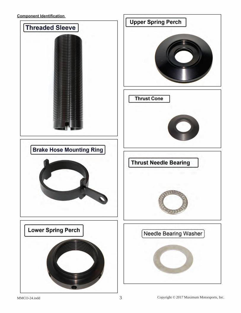
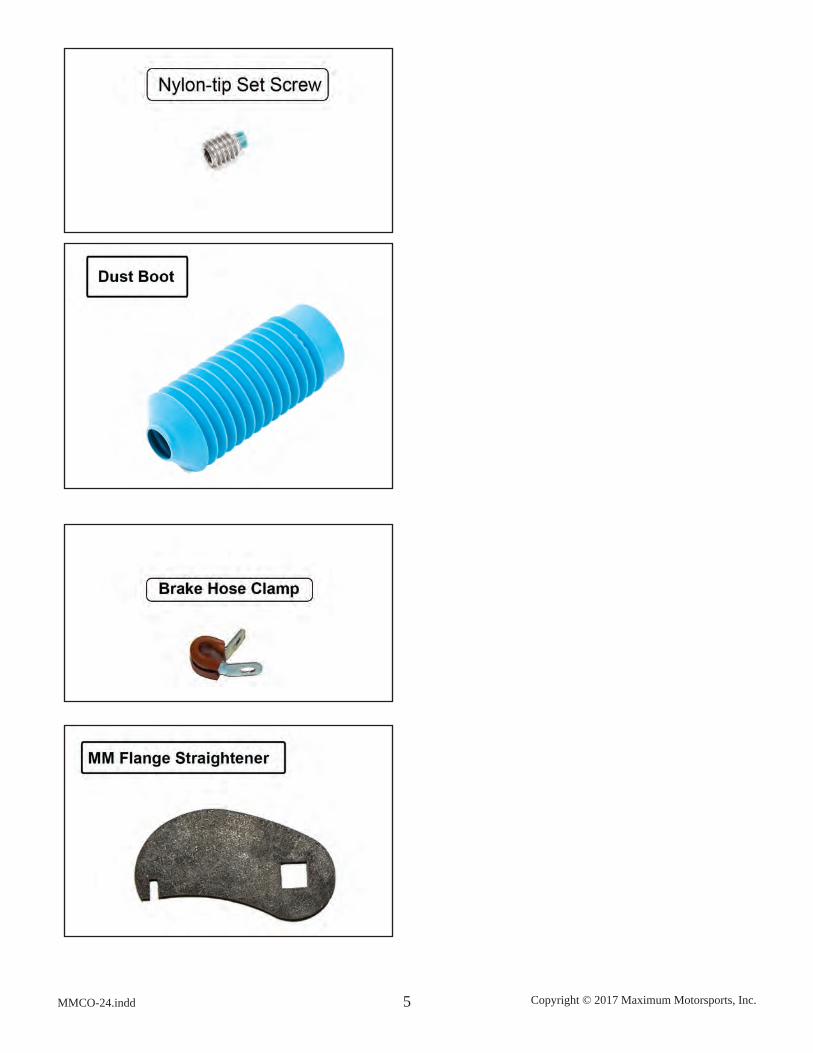
Description QTYThreaded Sleeve 2Brake Hose Mounting Ring 2Lower Spring Perch 2Upper Spring Perch 2Thrust Cone 2Thrust Needle Bearing 2Needle Bearing Washer 416mm ID x .12” long spacer bushing 216mm ID x .24” long spacer bushing 216mm ID x .48” long spacer bushing 47/8” ID x .5” long spacer bushing 217mm ID Thrust Washer 2Thick O-ring 2Thin O-ring 25/32” Allen wrench 1Nylon-tip Set Screw 2Dust Boot 2Brake Hose Clamp 2MM Flange Straightener 11/4 - 20 x 3/4 G5 zinc bolt 21/4 - 20 G5 zinc Nylock nut 21/4 SAE G8 flat yellow zinc washer 4Installation Instructions 1
Copyright © 2017 Maximum Motorsports, Inc.MMCO-24.indd 3
Component Identification

Copyright © 2017 Maximum Motorsports, Inc. 4 MMCO-24.indd
Copyright © 2017 Maximum Motorsports, Inc.MMCO-24.indd 5

Copyright © 2017 Maximum Motorsports, Inc. 6 MMCO-24.indd
Installation
1. Measure the front ride height to the top of the fender arch on both sides of the car. Record the measure-ments for future reference.
2. Loosen, but do not remove, the strut top retaining nuts. Then raise the front of the car and place it securely on jack stands. The car must be raised high enough on jack stands so that when the control arm pivots down-wards to vertical, it will not touch the ground.
3. Remove both front wheels.
4. Unbolt the brake caliper assembly and hang it securely from the chassis.
WARNING: Do NOT let the caliper hang from the brake hose, as this will cause unseen damage to the hose.
5. On 1994-04 vehicles, remove the front brake rotor. On 1979-93 vehicles, the rotor can remain on the spindle.
6. Disconnect the outer tie-rod end from the spindle.
7. Disconnect the swaybar end-link from the control arm.

Copyright © 2017 Maximum Motorsports, Inc.MMCO-24.indd 7
8. If the car is equipped with ABS, carefully unhook the sensor’s wire from the mounting bracket on the strut to get enough slack in the wire to remove the sensor from the spindle. Remove the sensor-to-spindle bolt, and carefully remove the sensor from the spindle. Remove the mounting bracket from the strut.
9. From the front of the car, place a floor jack under the control arm and slightly compress the spring to sup-port the control arm when the strut top retaining nut is removed.
10. Loosen, but do not remove, the two bolts holding the strut housing to the spindle.
11. Remove the strut top retaining nut.
12. Remove the two bolts that hold the strut housing to the spindle, and carefully remove the strut from the car.
13. Carefully lower the control arm with the jack and remove the spring. If necessary, use a spring compres-sor. Often, aftermarket springs are shorter and can be gently “popped” out once the control arm is lowered far enough. Stock springs are quite long and require a spring compressor for safe removal.
Copyright © 2017 Maximum Motorsports, Inc. 8 MMCO-24.indd
14. Be sure to remove the upper spring isolator. Some-times they stick to the upper spring perch.
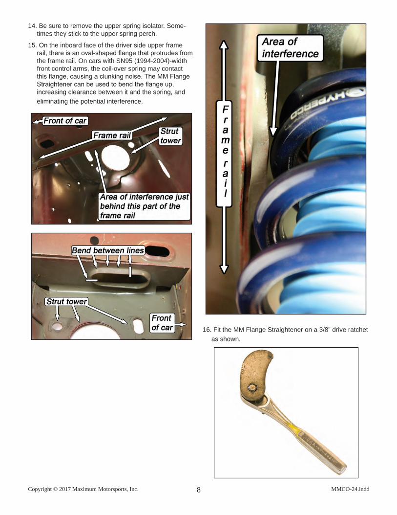
15. On the inboard face of the driver side upper frame rail, there is an oval-shaped flange that protrudes from the frame rail. On cars with SN95 (1994-2004)-width front control arms, the coil-over spring may contact this flange, causing a clunking noise. The MM Flange Straightener can be used to bend the flange up, increasing clearance between it and the spring, and eliminating the potential interference.
16. Fit the MM Flange Straightener on a 3/8” drive ratchet as shown.
Copyright © 2017 Maximum Motorsports, Inc.MMCO-24.indd 9
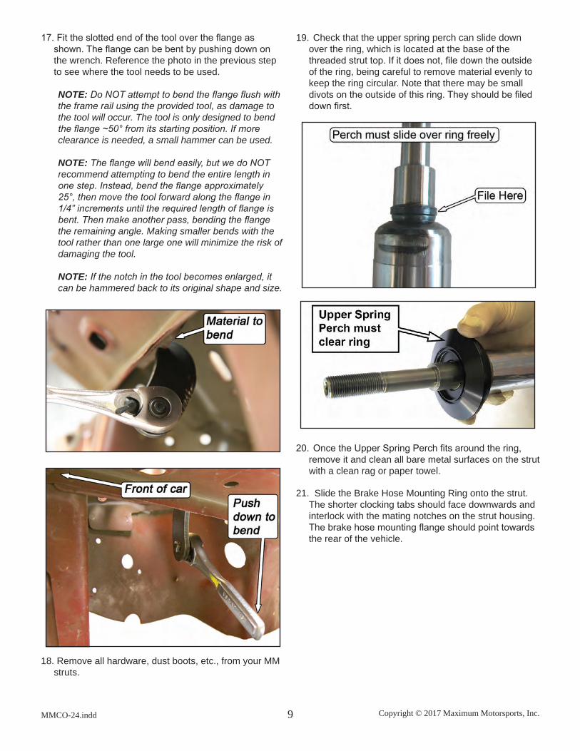
17. Fit the slotted end of the tool over the flange as shown. The flange can be bent by pushing down on the wrench. Reference the photo in the previous step to see where the tool needs to be used.
NOTE: Do NOT attempt to bend the flange flush with the frame rail using the provided tool, as damage to the tool will occur. The tool is only designed to bend the flange ~50° from its starting position. If more clearance is needed, a small hammer can be used.
NOTE: The flange will bend easily, but we do NOT recommend attempting to bend the entire length in one step. Instead, bend the flange approximately 25°, then move the tool forward along the flange in 1/4” increments until the required length of flange is bent. Then make another pass, bending the flange the remaining angle. Making smaller bends with the tool rather than one large one will minimize the risk of damaging the tool.
NOTE: If the notch in the tool becomes enlarged, it can be hammered back to its original shape and size.
18. Remove all hardware, dust boots, etc., from your MM struts.
19. Check that the upper spring perch can slide down over the ring, which is located at the base of the threaded strut top. If it does not, file down the outside of the ring, being careful to remove material evenly to keep the ring circular. Note that there may be small divots on the outside of this ring. They should be filed down first.
20. Once the Upper Spring Perch fits around the ring, remove it and clean all bare metal surfaces on the strut with a clean rag or paper towel.
21. Slide the Brake Hose Mounting Ring onto the strut. The shorter clocking tabs should face downwards and interlock with the mating notches on the strut housing. The brake hose mounting flange should point towards the rear of the vehicle.

Copyright © 2017 Maximum Motorsports, Inc. 10 MMCO-24.indd
22. Slide the threaded sleeve down over the strut hous-ing, unthreaded end first, until the tabs on the Brake Hose Mounting Ring interlock with the notches on the bottom of the threaded sleeve.
23. If not already installed, thread the Lower Spring Perch onto the threaded sleeve.
24. Install the bellows-style dust boot onto the strut shaft. It should seat below the ring referenced in Step 19.
NOTE: Check that the top of the dust boot has been trimmed down to the proper height, as shown below. If not, trim it enough (a power sander works well) so it seats below the ring referenced in Step 19.
25. Use a Moly wheel bearing grease to lube the thick O-ring and slide it over the strut shaft until it rests on the top of the dust boot.
26. Place the 2-1/2” diameter Coil-Over Spring onto the Lower Spring Perch. Position the Lower Spring Perch so the top of the spring is even with the top convolu-tion in the dust boot.
27. Grease the thin O-ring and place it into the groove machined into the top surface of the Upper Spring Perch.
Copyright © 2017 Maximum Motorsports, Inc.MMCO-24.indd 11
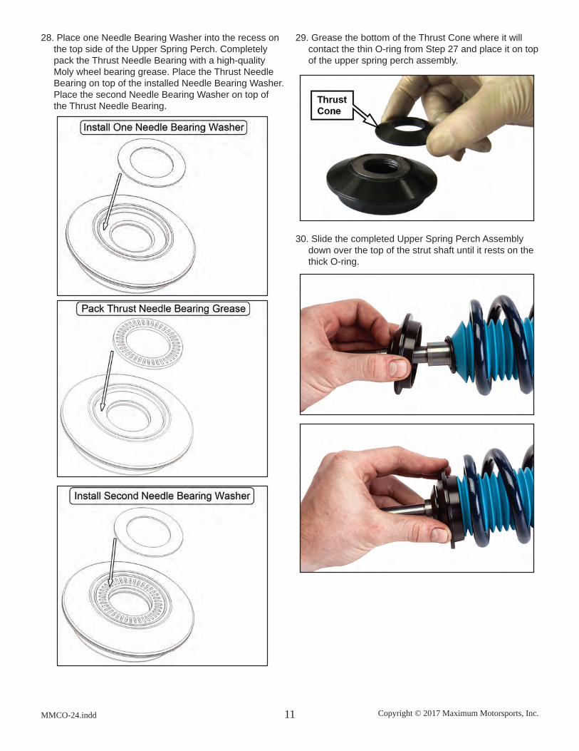
28. Place one Needle Bearing Washer into the recess on the top side of the Upper Spring Perch. Completely pack the Thrust Needle Bearing with a high-quality Moly wheel bearing grease. Place the Thrust Needle Bearing on top of the installed Needle Bearing Washer. Place the second Needle Bearing Washer on top of the Thrust Needle Bearing.
29. Grease the bottom of the Thrust Cone where it will contact the thin O-ring from Step 27 and place it on top of the upper spring perch assembly.
30. Slide the completed Upper Spring Perch Assembly down over the top of the strut shaft until it rests on the thick O-ring.

Copyright © 2017 Maximum Motorsports, Inc. 12 MMCO-24.indd
31. Slide the large 7/8” inside diameter Spacer Bushing over the strut shaft until it rests on the Thrust Cone.
32. Place the 17mm inside diameter Thrust Washer over the top of the strut shaft. Don’t be surprised if the Thrust Washer will not contact the shoulder of the shaft. The thick O-ring from Step 25 will be com-pressed and expanded during installation, and the Thrust Washer will then contact the shoulder of the strut shaft.
NOTE: Some companies’ C/C plates have a fixed-type spacer bushing pressed into the spherical bearing. With these types of C/C plates, and you may not be able to maximize bump travel in Step 39.
33. Take one of the provided 16mm ID x .48” long spacers and place it over the strut shaft. Slide it down until it sits on top of the Thrust Washer.
NOTE: Install C/C plates if the car is not equipped with them at this time.

Copyright © 2017 Maximum Motorsports, Inc.MMCO-24.indd 13
34. Take the entire strut assembly to the car and place the strut shaft top into the spherical bearing of the C/C plate. While holding the strut assembly as high as it will go in the C/C bearing, stack a .12”, .24” and .48” long 16mm ID spacer on top of the strut shaft. Tighten the strut top retaining nut to a snug setting.
NOTE: C/C plate not installed in car for visibility.
35. If the alignment has not been set, the caster must be roughly estimated before continuing. If using MM C/C plates:
• For 1979-93 Mustangs, slide the bearing cup of the C/C plate as far as it will go toward the firewall and torque to 32 lb-ft.
• For 1994-04 Mustangs, slide the bearing cup of the C/C plate in the middle of its caster adjustment range and torque to 32 lb-ft.
36. Slide the strut ears over the spindle ear, install both mounting bolts, and loosely thread on both nuts.
37. Loosely reattach the outer tie-rod to the steering arm on the spindle.
38. Check clearance between the Upper Spring Perch
Assembly and the bottom of the C/C plate. The tight-est spot will be toward the rearward bolt heads on the C/C plate bottom plates. Check clearance at full droop while the suspension is being steered. Jack the control arm up to ride height and check for clearance while the suspension is being steered. The minimum clearance should be between 1/8” to 1/4”.
TIP: Remember that the relative position of the Up-per Spring Perch will change with different front end alignment settings. Be sure to allow clearance for any future caster/camber settings you may use. A small mirror will be necessary to check all clearances.
NOTE: Spring and dust boot not shown for clarity.

Copyright © 2017 Maximum Motorsports, Inc. 14 MMCO-24.indd
39. The vertical position of the Upper Spring Perch As-sembly is adjusted by exchanging spacers between the upper and lower spacer stacks (see photo below). If the tightest clearance is less than 1/8”, move the next appropriate Spacer Bushing (or combination of Spacer Bushings) from the Upper Spacer Stack to the Lower Spacer Stack to gain necessary clearance. If clearance is in excess of 1/4”, use the next appropri-ate thinner Spacer Bushing (or combination of Spacer Bushings) to reduce the clearance and gain as much bump travel as possible.
40. After the proper combination of Spacer Bushings to place underneath the C/C plate has been determined, secure the strut shaft to the C/C plate with the strut top retaining nut. At a minimum, one Spacer Bushing is required between the spherical bearing and the strut top retaining nut. Wait until the car is on the ground to torque the retaining nut.
NOTE: All the provided Spacer Bushings must be in-stalled on the struts. They are required to prevent the strut top nut from running out of threads when tighten-ing.
41. The MM struts have a larger bottom bolt hole in the strut-mounting ear to allow for production variations in the location of the holes in the spindles. This enlarged hole allows the spindle orientation, relative to the strut, to be changed by 1.4 degrees, before the bolts are tightened. This provides 1.4 degrees of camber adjust-ment at the strut-to-spindle interface. It is important to tighten this joint with the spindle held in either the maximum positive or maximum negative camber position on both sides of the car. This way, when you disassemble the front suspension in the future, it will not be necessary to realign the car if you reassemble it with the spindle in the same maximum positive or maximum negative position relative to the strut ears.
Whether you choose the maximum negative or maxi-mum positive position is a function of other suspension parts on your car. See the charts below for suggested spindle orientation settings.
1979-93 MustangFront Control Arm Model
Ford 1979-93 or MMFCA
for 1979-93
Ford 1994-04 or MMFCA for
1994-04
Spindle Year
1979-93 Negative Positive1994-04 Negative Positive
1994-04 MustangAuto-X or Road Race Use NegativeDrag Race or Street Use Positive
42. To position the spindle in the maximum negative posi-tion, push the strut housing inwards, near the spindle mounting ears, while tightening the strut-to-spindle bolts.
To position the spindle in the maximum positive posi-tion, pull the strut housing outwards, near the spindle mounting ears, while tightening the strut-to-spindle bolts.
Torque the strut-to-spindle bolts to 192 lb-ft.
43. Torque the outer tie-rod nut to factory specification and install a new cotter pin.
44. Do your first check for potential interference between the coil-over spring, and the brake hose where it at-taches to the hard line. Use the jack to move the sus-pension from full droop to full bump, and check while someone moves the steering wheel back and forth. 1994-04 cars usually do not have any interference problems, but 1979-93 cars or any car using 1979-93 length front control arms may require relocating the brake hard-line mounting bracket rearward 1”. (Refer to addendum at the end of these instructions.)
NOTE: In rare cases there may be an interference be-tween the Spring/Lower Spring Perch and the stock K-member near where the stock spring was located. To remedy that situation you will need a hand-held grinder to clearance the K-member. After the installation is complete, with final ride height set, another check for interference between components must be made.
45. Adjust the height of the Lower Spring Perch. If the installed Spring has a rate of between 150 and 200lbs/in, adjust the height of the Lower Spring Perch so that the top of the Spring just touches the bottom of the Upper Spring Perch. If the installed Spring has a rate of between 225 and 325lbs/in, adjust the Lower Spring

Copyright © 2017 Maximum Motorsports, Inc.MMCO-24.indd 15
Perch so that the top of the Spring is about 1.25” from the Upper Spring Perch. If the installed Spring is stiffer than 325lbs/in, adjust the Lower Spring Perch so that the top of the Spring is about 2” from the Upper Spring Perch.
NOTE: When using stiffer Springs (greater than about 200lbs/in), the Spring may not touch the Upper Spring Perch when the suspension is at full droop travel (car raised up off of the ground by the frame so that the tires are in the air). This is normal and does not indicate any problem with the installation. Changing to a different length Spring will NOT have any affect on this. If you have questions about this, contact Maxi-mum Motorsports Tech department.
46. If the car has ABS, the mounting bracket for the sen-sor will need to be modified to clear the Lower Spring Perch.
47. Use two sets of pliers to hold and bend the bracket forward near the base.
48. Then carefully bend it upward near the end where the wire attaches.
49. Reattach the mounting bracket to the spindle and adjust the bends if necessary to keep the mounting bracket close to the strut. Install and tighten the retain-ing nut for the mounting bracket.
50. Clean any dirt from the tip of the ABS sensor and reattach the ABS sensor to the spindle. Reattach the sensor’s wire to the mounting bracket.

Copyright © 2017 Maximum Motorsports, Inc. 16 MMCO-24.indd
51. Reattach the swaybar end-link to the control arm. Do not overtighten the end-link bushings.
52. If you removed the brake rotor, reinstall it now.
53. Reattach the brake caliper and torque the mounting bolts to factory specifications.
54. If using a brake hose that has a long tubular metal section attached to the banjo fitting, skip to Step 59. This type of hose will not work with the Brake Hose Tab mounting feature.
55. (Flexible Hoses ONLY): Slide the Brake Hose Clamp onto the hose as shown.
56. (Flexible Hoses ONLY): The stack-up for the Brake Hose Clamp hardware is shown below.
57. (Flexible Hoses ONLY): Place a washer under the head of the bolt and slide it through the Brake Hose Clamp.
58. (Flexible Hoses ONLY): Pass the bolt through the Brake Hose Tab, place a washer onto the bolt, and secure the bolt with the Nylock nut.
WARNING: The brake hose end that attaches to the caliper may need to be reclocked in order to provide enough slack in the hose to attach the Brake Hose Clamp to the Brake Hose Tab. If reclocked, the front brakes must be bled per the factory manual.

Copyright © 2017 Maximum Motorsports, Inc.MMCO-24.indd 17
59. Mount the tire and wheel. Check for clearance to the Coil-Over components. Minimum clearance between the tire or wheel and any of the coil-over components is 1/8”. Remember that the final ride height has not yet been set, and so the position of the Lower Spring Perch may change.
60. Lower the car to the ground. Torque the lug nuts to factory specifications.
61. Torque the strut shaft retaining nut to 65 lb-ft.
62. Roll the car back and forth to settle the suspension.
63. Measure the ride height, as in Step 1. Adjust the ride height to match the previous measurement, or change the ride height as desired.
64. To change ride height, carefully jack the front of the car up and place it on jack stands. Rotate the Lower Spring Perch to raise the car up or down.
NOTE: The distance from the bottom of the lower spring perch, to the bottom of the threaded sleeve, on each side of the car must be the same. If these distances on each side of the car are set differently, in an attempt to level the car, the corner weights will most likely end up very unequal. This will result in poor handling and other problems. If you are attempt-ing to make the ride heights on both sides of the car perfectly equal, take the car to a shop that special-izes in road race or autocross setups and has corner weight scales.
NOTE: Spring rates 200 lbs/in and lower usually need to be preloaded to achieve a proper ride height. The MMT-2 Spanner Wrench (available separately) is de-signed to help rotate the Lower Spring Perch in these cases.
65. After the ride height is set, tighten the set screw a little at a time until it takes some resistance to rotate the Lower Spring Perch on the Threaded Sleeve. Only a very small amount of friction is needed to keep the lower spring perch from rotating. Any extra force on the set screw will result in damage to the Nylon tip and the Threaded Sleeve.
66. Have the front end professionally aligned. Remem-ber that any time the ride height is changed, the camber and toe settings will have to be adjusted.
Copyright © 2017 Maximum Motorsports, Inc. 18 MMCO-24.indd
3430 Sacramento Dr., Unit DSan Luis Obispo, CA 93401
Telephone: 805/544-8748Fax: 805/544-8645
www.maximummotorsports.com
Brake Line Relocation Addendum, 1979-93 ONLY
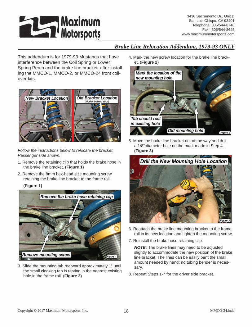
This addendum is for 1979-93 Mustangs that have interference between the Coil Spring or Lower Spring Perch and the brake line bracket, after install-ing the MMCO-1, MMCO-2, or MMCO-24 front coil-over kits.
Follow the instructions below to relocate the bracket. Passenger side shown.1. Remove the retaining clip that holds the brake hose in
the brake line bracket. (Figure 1) 2. Remove the 8mm hex-head size mounting screw
retaining the brake line bracket to the frame rail. (Figure 1)
3. Slide the mounting tab rearward approximately 1” until the small clocking tab is resting in the nearest existing hole in the frame rail. (Figure 2)
4. Mark the new screw location for the brake line brack-et. (Figure 2)
5. Move the brake line bracket out of the way and drill a 1/8” diameter hole on the mark made in Step 4. (Figure 3)
6. Reattach the brake line mounting bracket to the frame rail in its new location and tighten the mounting screw.
7. Reinstall the brake hose retaining clip. NOTE: The brake lines may need to be adjusted
slightly to accommodate the new position of the brake line bracket. The lines can be easily bent the small amount needed by hand; no tubing bender is neces-sary.
8. Repeat Steps 1-7 for the driver side bracket.